NASA Contractor Report: 1723_2 _ 19840014515 i Technology Review of Flight Crucial Ftight Control Systems H.A, Rediess and E.C, Buckley HR Textron Inc, Systems Engineering Division Irvine,CA 9271,$ Contract NAS1-17403 _.., _._ _.P,_ r_,_,,,, _r r',','.i I£_4 April 1984 J.._.f",GLEY RESEARCHCENfER LI_qRARY, NASA H.__:.. ?'1-_..._ VIRGII'41A NASA NationalAeronauticsand Space Administration LangleyResearchCenter Hampton,Virginia 23665

Welcome message from author
This document is posted to help you gain knowledge. Please leave a comment to let me know what you think about it! Share it to your friends and learn new things together.
Transcript
!I
NASA Contractor Report: 1723_2
|
_ 19840014515i
| Technology Review of Flight Crucial
II Ftight Control Systems
III
H.A, Rediess and E.C, Buckley
II HR Textron Inc,Systems Engineering Division
Irvine,CA 9271,$
!I Contract NAS1-17403 _.., _.__.P,_r_,_,,,,_r
I r',','.i I£_4April 1984
J.._.f",GLEYRESEARCHCENfER
I LI_qRARY,NASAH.__:..?'1-_..._ VIRGII'41A
I NASA- NationalAeronauticsandSpace Administration
I LangleyResearchCenterHampton,Virginia23665
I

i NASA ContractorReport 172332
II
TECHNOLOGY REVIEW
III OF
l FLIGHT CRUCIAL FLIGHT CONTROL SYSTEMS
!I APRIL 1984
IIi H.A. Rediess
E. C. Buckley
i HR Textron Inc.Systems EngineeringDivision2485 McCabeWay
I Irvine, CA 92714
II Contract NASI-17403
I NASA,NationalAeronautics and
i S!3aceAdministrationLangley ResearchCenterHampton. Virgmra23665
I! ,4,/_4-ota5-83--_

IIIIIIIIIIIIIIIIIII
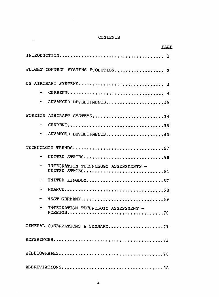
IIi CONTENTS
PAGE
U INTRODUCTION ...................................... 1
I FLIGHT CONTROL SYSTEMS EVOLUTION .................. 2
i US AIRCRAFT SYSTEMS ............................... 3- CURRENT 4ooeeeeoeeooooeeeeee ooeoeeooooooeo oo
i - ADVANCED DEVELOPMENTS 18• • • • • o • • • • • • • o e o o o o o e
n FOREIGN AIRCRAFT SYSTEMS .......................... 34- CORRENT 3 5ooooeeooooo ooo ooeoo eoeeooootoeoeooo
I - ADVANCED DEVELOPMENTS 40• • • • • qJ ee o o o 4 e qp e o eoo o e
I TECHNOLOGYTRENDS.................................57- UNITED STATES 58oeoeoooeoeoooooooooeot oooeoeo
I - INTEGRATION TECHNOLOGY ASSESSMENTS -UNITED STATES ............................. 64
I - UNITED KINGDOM 67• • • • • • • • • • • • • • • • • • • • e o e o o o o o
i -- FRANCE .................................... 6 8- WEST GERMANY 69• oeoo oQ oooooeQ eQe eoeo o4 oo eoqJ oo
I - INTEGRATION TECHNOLOGY ASSESSMENT -FORE IGN ................................... 70
i GENERAL OBSERVATIONS & SUMMARY....................71
m REFERENCES........................................73
I B IBL IOGRAPHY ...................................... 78
m ABBREVIATIONS ..................................... 88
I i

IIIIIIIIIIIIIIIIIII
INTRODUCTION
A survey of foreign technology in flight crucial flightcontrols is being conducted for NASA Langley Research Centeras a data base for planning future research and technologyprograms. Free world countries were surveyed with primaryemphasis on Western Europe because that is where themost advanced technology resides. The survey includes majorcontemporary systems on operational aircraft, R&D flightprograms, advanced aircraft developments, and major researchand technology programs. The survey was not intended to bean in-depth treatment of the technology elements, but rathera study of major trends in systems level technology. Theinformation was collected from open literature, personalcommunications and a tour of several companies, governmentorganizations and research laboratories in the UnitedKingdom, France, and the Federal Republic of Germany. Thisreport provides the results of the survey.
Some of the material presented was derived from abriefing to the NASA Administrator by Mr. Kenneth Szalaifrom Ames Research Center, Dryden Flight Research Facility,on the technology tour of Europe that Mr. Szalai and the Dr.Rediess conducted in 1983, and is used with the permissionof Mr. Szalai.
This survey was conducted under contract NASI-17403 andthe Technical Representative of the Contracting Officer wasMr. Cary Spitzer, NASA Langley Research Center. Thematerial presented herein solely represents the findings andopinions of the authors and is not to be construed as beingendorsed by the US Government or representatives of theNational Aeronautics and Space Administration.
1

IIIIIIIIIIIIIIIIIII
II FLIGHT CONTROL SYSTEMS EVOLUTION
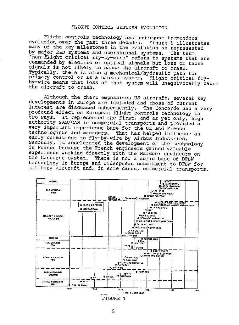
Flight controls technologyhas undergonetremendous
i evolutionover the past three decades. Figure 1 illustratesmany of the key milestonesin the evolutionas representedby major R&D systems and operationalsystems. The term"non-flightcritical fly-by-wire"refers to systems that are
I by or optical signals but loss of thosecommanded electricsignals is not likely to cause the aircraft to crash.Typically,there is also a mechanical/hydraulicpath for
I primary control or as a backup system. Flight critical fly-by-wire means that loss of that systemwill unequivocallycausethe aircraft to crash.
I Although the chart emphasizesUS aircraft,several keydevelopmentsin Europe are includedand those of current
I interestare discussedsubsequently. The Concordehad a veryprofound effect on European flight controls technologyintwo ways. It representedthe first, and as yet only, highauthoritySAS/CAS in commercialtransportsand provided a
I very importantexperiencebase for the UK and Frenchtechnologistsand managers. That has helped influenceanearly commitmentto fly-by-wireby Airbus Industries.
I Secondly,it acceleratedthe developmentof the technologyin France because the French engineersgained valuableexperienceworking directlywith the Marconi engineerson
i the Concordesystem. There is now a solid base of DFBWtechnologyin Europe and widespread commitmentto DFBW formilitary aircraft and, in some cases, commercialtransports.
I nlGITAL I • JVX I• LAVI (ISRAEL)
JAS 39 (SWEDEN)_AOOCS-OPTJCAL
i FLT. CRITICAL 0 AFTUF.16 I
FEW O JAGUAR DFBW (UK)•SPAC,SHU.LEIL"NAR O------"OF_DFEW !- --_
............. MODULE • -- --I-- "-QAGUST"A--A-129TAIL ROTOR0 R AND O SYSTEM I • 8-767 DFCSIA.310 DFCS AND SPOILER
i _ • OC,HOOFCS
• OPERATIONAL OVALT I: • F._8 DFC_ I
NON.FLT. CRITICAL • CH.S3E DFCS IAFC.edFEW • TORNADO AUTOPILOT
0 YC-14 FLEEROPTICS (MARCONI
I °°°°°°I• .JA-37 VIGGI_H (SWEDEN)O A-TDIGITAC
O CH.47 TAGS
ANALOG I .Fe,6"'RAGE
I FLT. CRITICAL 0 HLH OEMOFEW YF,18 0 I I
....... O F.4 SFC5
• EELL 214 ST ELEVATOR_ / 0 AN.IG TAIL ROTOR0 CH-4/VALT
i NON.FLT. CRITICAL
FBW O C-141 FBW• CONCORD THROTTLE
Oe.4Twe.,o ] _; _ _ _0 8-47 FEW
• rHIGH AUTHORITY "7 •F.IS • TORNADO
LIMITED AUTHORITY
SAS F49 • I
_960 1960 1170 lg80 _W)0 20O0
I ........ FIRST FL)GHT YEARFIGURE 1

IIIIIIIIIIIIIIIIi!I
IIIIIIIIIII U.S. AIRCRAFT SYSTEMS
IIIIIIIII

IIIIIIIIIIiIIIIII!!
I
I F-15 AND F-16
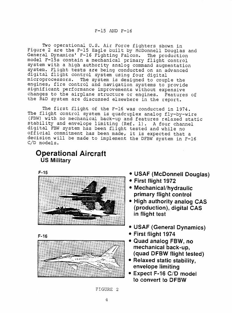
i Two operational U.S. Air Force fighters shown inFigure 2 are the F-15 Eagle built by McDonnell Douglas and
i General Dynamics' F-16 Fighting Falcon. The productionmodel F-15s contain a mechanical primary flight controlsystem with a high authority analog command augmentationsystem. Flight tests are being conducted on an advanced
i digital flight control system using four digitalmicroprocessors. The system is designed to couple theengines, fire control and navigation systems to provide
i significant performance improvements without expensivechanges to the airplane structure or engines. Features ofthe R&D system are discussed elsewhere in the report.
I The first flight of the F-16 was conducted in 1974.The flight control system is quadruplex analog fly-by-wire(FBW) with no mechanical back-up and features relaxed static
i stability and envelope limiting (Ref. i). A four channeldigital FBW system has been flight tested and while noofficial commitment has been made, it is expected that a
I decision will be made to implement the DFBW system in F-16C/D models.
i Operational AircraftUS Military
I • USAF (McDonnell Douglas)F-15
• First flight 1972
i • Mechanical/hydraulicprimary flight control
• High authority analog CASI (production), digital CAS
in flight test
!• USAF (General Dynamics)
I F-16 • First flight 1974• Quad analogFBW,nomechanical back-up,
I (quad DFBW flight tested)• Relaxed static stability,
i envelope limiting• Expect F-16 C/D modelto convert to DFBW
I FIGURE 2
II
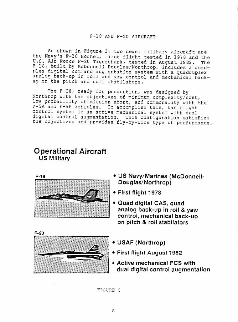
F-18 AND F-20 AIRCRAFT
IAs shown in Figure 3, two newer military aircraft are
the Navy's F-18 Hornet, first flight tested in 1978 and the iU.S. Air Force F-20 Tigershark, tested in August 1982. The IF-18, built by McDonnell Douglas/Northrop, includes a quad-plex digital command augmentation system with a quadruplexanalog back-up in roll and yaw control and mechanical back- •up on the pitch and roll stabilators.
m
The F-20, ready for production, was designed by •Northrop with the objectives of minimum complexity/cost,low probability of mission abort, and commonality with theF-5A and F-SE vehicles. To accomplishthis, the flight •control system is an active mechanical system with dual |digital control augmentation. This configuration satisfiesthe objectives and provides fly-by-wire type of performance, i
i
IOperationalAircraft
US Military i
= US Navy/Marines (McDonnell- nF-18
Douglas/Northrop)
• First flight 1978 I
• Quad digital CAS, quadanalog back-up in roll & yaw ncontrol, mechanical back-up
on pitch & roll stabilators nF-20
• USAF (Northrop) I• First flight August 1982
i• Active mechanical FCS with I,_,_,_,dual digital control augmentation
FIGURE 3 I
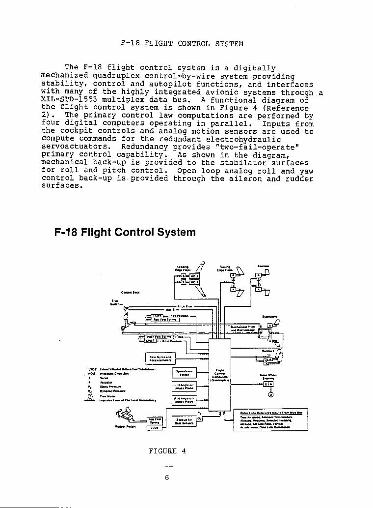
II F-18 FLIGHT CONTROL SYSTEM
I The F-18 flight control system is a digitallymechanized quadruplex control-by-wire system providingstability, control and autopilot functions, and interfaces
i with many of the highly integrated avionic systems through aMIL-STD-1553 multiplex data bus. A functional diagram ofthe flight control system is shown in Figure 4 (Reference2). The primary control law computations are performed by
I operating parallel. Inputs fromfour digital computers in
the cockpit controls and analog motion sensors are used tocompute commands for the redundant electrohydraulic
I servoactuators. Redundancy provides "two-fail-operate"primary control capability. As shown in the diagram,mechanical back-up is provided to the stabilator surfaces
I for roll and pitch control. Open loop analog roll and yawcontrol back-up is provided through the aileron and ruddersurfaces.
!
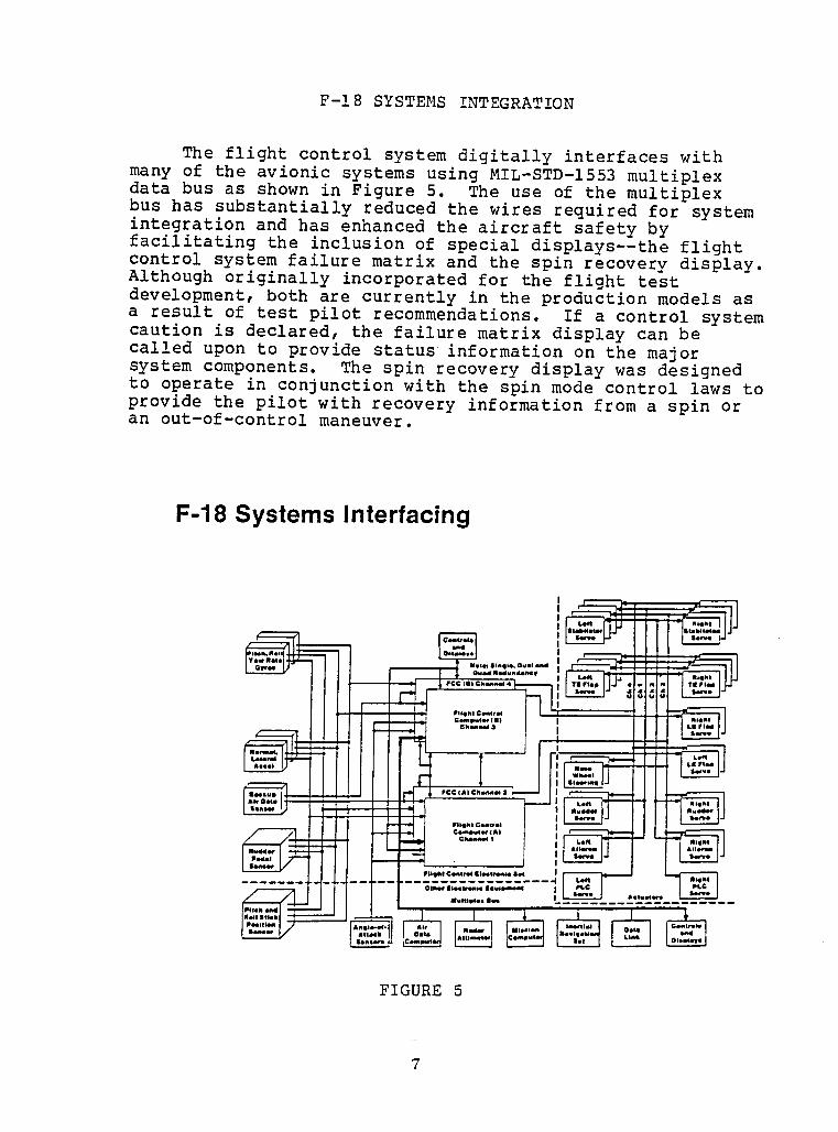
|F-18 SYSTEMS INTEGRATION I
The flight control system digitally interfaceswith |many of the avionic systems using MIL-STD-1553multiplexdata bus as shown in Figure 5. The use of the multiplexbus has substantiallyreduced the wires required for system nintegrationand has enhanced the aircraft safety by |facilitatingthe inclusionof special displays--theflightcontrol system failure matrix and the spin recovery display. |Although originallyincorporatedfor the flight test ndevelopment,both are currently in the productionmodels asa result of test pilot recommendations. If a control system •caution is declared,the failurematrix display can be Icalled upon to provide status informationon the majorsystem components. The spin recovery display was designedto operate in conjunctionwith the spin mode control laws to |provide the pilot with recovery informationfrom a spin oran out-of-controlmaneuver.
I
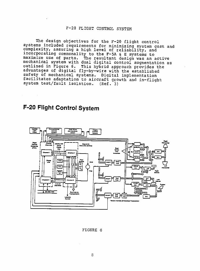
F-20 FLIGHT CONTROL SYSTEM
The design objectives for the F-20 flight controlsystems included requirements for minimizing system cost andcomplexity, assuring a high level of reliability, andincorporating commonality to the F-SA & E systems tomaximize use of parts. The resultant design was an activemechanical system with dual digital control augmentation asoutlined in Figure 6. This hybrid approach provides theadvantages of digital fly-by-wire with the establishedsafety of mechanical systems. Digital implementationfacilitates adaptation to aircraft growth and in-flight
system test/fault isolation. (Ref. 3)
F-20 Flight Control System
/L_/_,, ,,I_ .=-
l il I'11 \ i'i _, I' II U'.--" "144-1_ IFII=II-- II
II ilII_ITNIII__- _, II _=_!1_-_=,
IIi FIGURE 6
I8
I
II
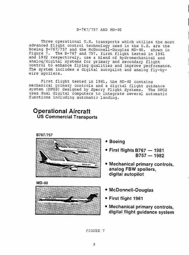
B-767/757 AND MD-80
iThree operational U.S. transports which utilize the most
advanced flight control technology used in the U.S. are the •Boeing B-767/757 and the McDonnell-Douglas MD-80, shown in |Figure 7. The B-767 and 757, first flight tested in 1981and 1982 respectively, use a blend of hydromechanical and manalog/digital
systems for primary and secondary flight Icontrol to enhance flying qualities and improve performance.The system includes a digital autopilot and analog fly-by-
wire spoilers. IFirst flight tested in 1981, the MD-80 contains
mechanical primary controls and a digital flight guidance []system (DFGS) designed by Sperry Flight Systems. The DFGS |uses dual digital computersto integrateseveral automatic
functions including automatic landing, i
Operational Aircraft |US Commercial Transports
!B767/757
• Boeing i
• First flights B767 -- 1981B757-- 1982 i
• Mechanical primary controls, []analog FBW spoilers, idigital autopilot
MD-80 I
• McDonnell-Douglas i• First flight 1981
• Mechanical primary controls, idigital flight guidance system
!FIGURE 7 I
' I
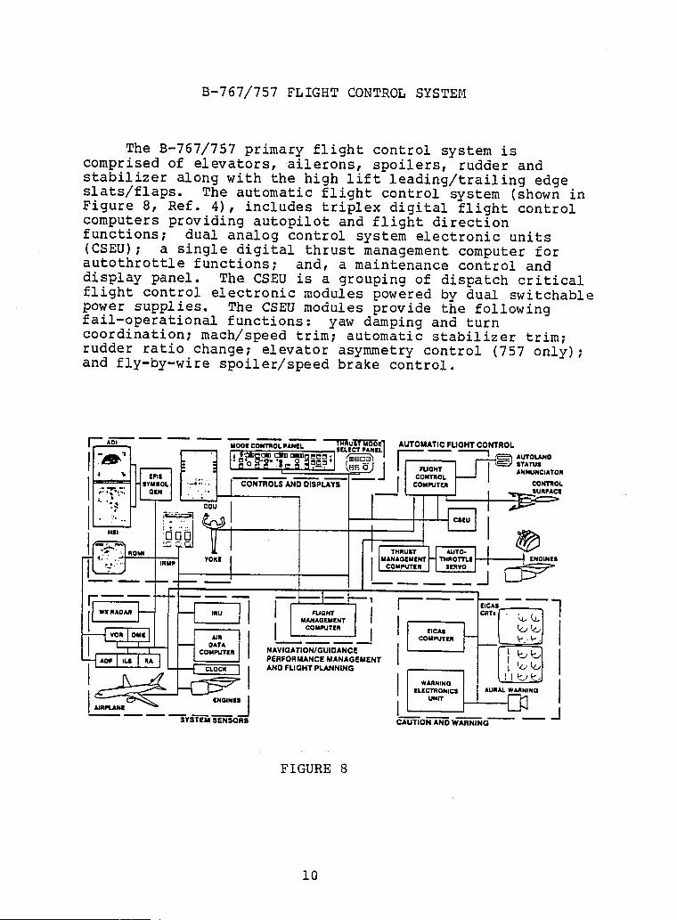
I B-767/757FLIGHT CONTROL SYSTEM
IThe B-767/757primary flight control system is
comprisedof elevators,ailerons, spoilers,rudder and
I stabilizer with the high lift leading/trailingedgealongslats/flaps. The automaticflight control system (showninFigure 8, Ref. 4), includes triplex digital flight control
I computersprovidingautopilotand flight directionfunctions; dual analog control system electronicunits(CSEU); a single digital thrust managementcomputerfor
I autothrottlefunctions; and, a maintenancecontrol anddisplay panel. The CSEU is a groupingof dispatchcriticalflight control electronicmodules powered by dual switchable
i power supplies. The CSEU modules provide the followingfail-operationalfunctions: yaw damping and turncoordination;mach/speedtrim; automaticstabilizertrim;rudder ratio change; elevatorasymmetrycontrol (757 only);
I and fly-by-wirespoiler/speedbrake control.
IAm, .............. "Tl:TAul_;5"_trl AUTOMATIC FUGHT CONTROL
I I I ! ! I!
I I I It , I I , I u_*_llulrNT I I I [ 1 I 1."_ _ I I
--_ wn IDu,,] I I .n I I I I co _t_ [- _ I
_'1"" I _ I L._,,', : l_°"_""I I PERFORMANCE MANAGI=MIENT ]I_1 I
SYSTEM SF.NSQRS CAUTION AND WARNING
IFIGURE 8
IIi 10
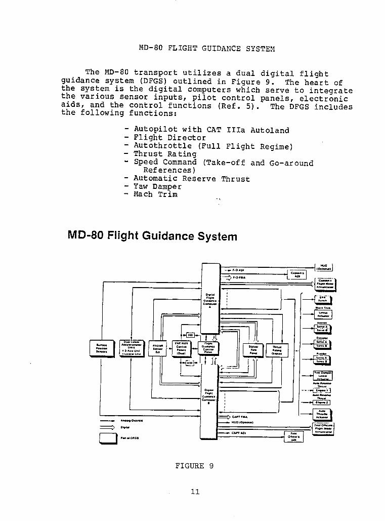
IMD-80 FLIGHT GUIDANCE SYSTEM I
m
The MD-80 transport utilizes a dual digital flight Nguidance system (DFGS) outlined in Figure 9. The heart ofthe system is the digital computers which serve to integrate m
the various sensor inputs, pilot control panels, electronic iaids, and the control functions (Ref. 5). The DFGS includes u
the following functions:
- Autopilot with CAT IIIa Autoland i- Flight Director- Autothrottle (Full Flight Regime) •- Thrust Rating N- Speed Command (Take-off and Go-around
References)Automatic Reserve Thrust i
- Yaw Damper- Mach Trim
FIGURE 9 I
11 n
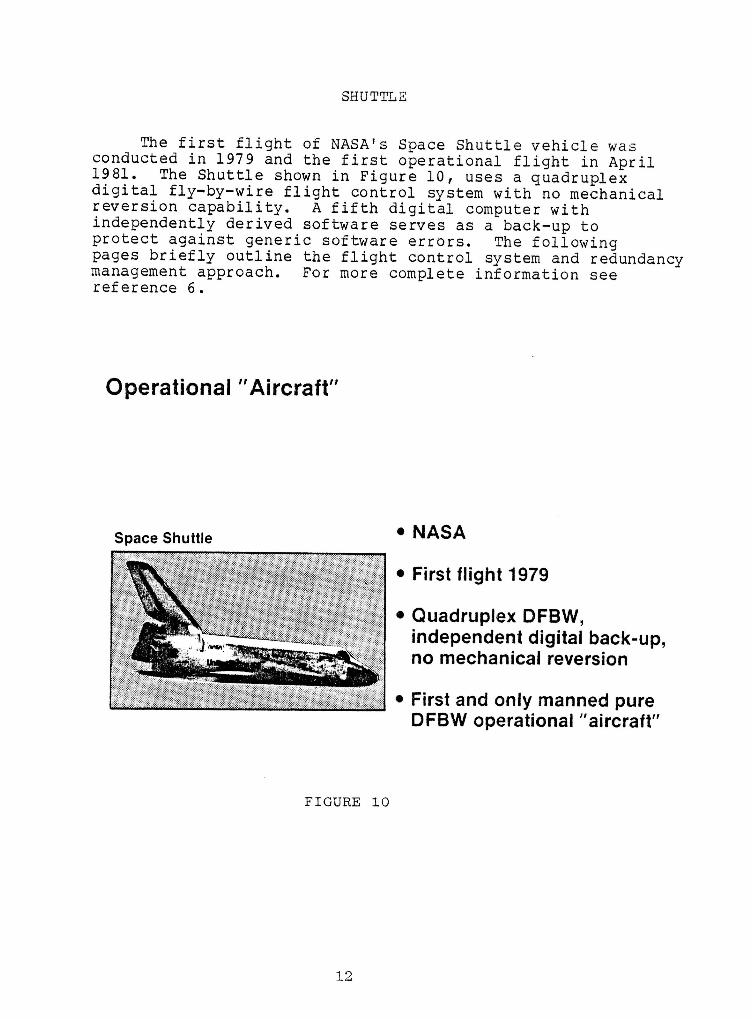
SHUTTLE
The first flight of NASA's Space Shuttlevehicle wasconducted in 1979 and the first operationalflight in April1981. The Shuttle shown in Figure i0, uses a quadruplexdigital fly-by-wireflight control systemwith no mechanicalreversioncapability. A fifth digital computerwithindependentlyderived software serves as a back-up toprotect against generic softwareerrors. The followingpages briefly outline the flight control system and redundancymanagementapproach. For more complete informationseereference6.
Operational"Aircraft"
Space Shuttle • NASA
• Firstflight 1979
• Quadruplex DFBW,independent digital back-up,no mechanical reversion
• First and only manned pure
I DFBW operational "aircraft"
IFIGURE I0
IIi
i 12
II
SHUTTLE FLIGHT CONTROL SYSTEM m
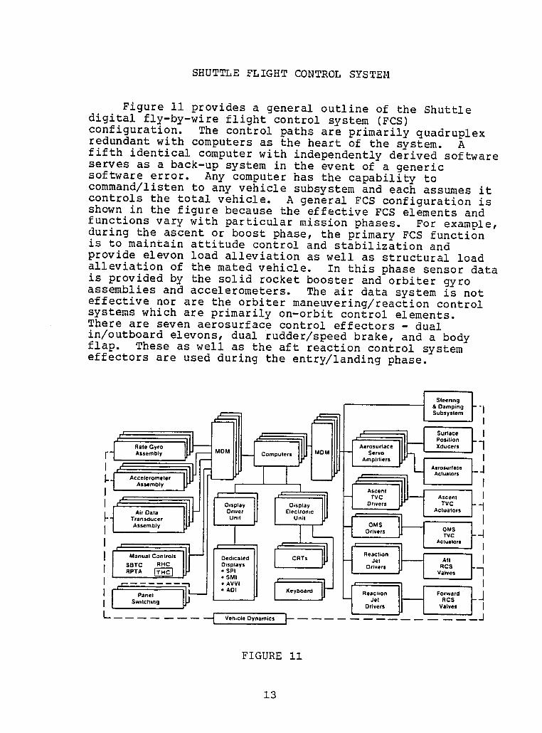
Figure ii provides a general outline of the Shuttle Idigital fly-by-wire flight control system (FCS)configuration. The control paths are primarily quadruplex mredundant with computers as the heart of the system. A |fifth identical computer with independently derived softwareserves as a back-up system in the event of a genericsoftware error. Any computer has the capability to []command/listen to any vehicle subsystem and each assumes it
m
controls the total vehicle. A general FCS configuration isshown in the figure because the effective FCS elements and •functions vary with particular mission phases• For example,during the ascent or boost phase, the primary FCS functionis to maintain attitude control and stabilization and •provide elevon load alleviation as well as structural load |alleviation of the mated vehicle. In this phase sensor datais provided by the solid rocket booster and orbiter gyro massemblies and accelerometers. The air data system is not |effective nor are the orbiter maneuvering/reaction controlsystems which are primarily on-orbit control elements.There are seven aerosurface control effectors - dual []in/outboard elevons, dual rudder/speed brake, and a bodyflap. These as well as the aft reaction control systemeffectors are used during the entry/landing phase. []
|
Seernl& Damping "ISubsystemI
IPosition
Rate Gyro Aerosurface Xducers
I" - Assembly Computers ServoAmplitiers I
ActuatOCS
... AccelerometerAssembly
AscentTVC Ascen!
I ,, Display Display Drivers TVC " "1
_-t Air Data O.ver Electronic Actuators
Transducer ill, J Untt Unit [
Assembly pJ OMSDrivers OMSTVC - -'1
AcIualors
I Manual Controls Dedicated CRTs Je! All I
SBTC RHC II I Displays Drivers RCS
RPTA _ IJ,,I •SPl Valves "'--_• SMI
_ ,a°e, i,___.,D, _eyOoard Reaction _o..rd_JSw tching _J Jet RCSI Drivers Valves I
L.. [ Vehicle Oynamtcs t J IFIGURE ii I
II SHUTTLE REDUNDANCYAPPROACH
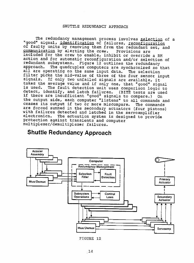
I The redundancy management process involves _ of a"good" signal, identification of failures, reconfigurationof faulty units by removing them from the redundant set, and
I communication the Provisions areby alerting crew.included for the crew to enable, inhibit or overridea RMaction and for automatic reconfigurationand/or selectionof
I redundant subsystems. Figure 12 outlines the redundancyapproach. The quadruplex computers are synchronized so thatall are operating on the same input data. The selection
I ilter picks the mid-value of three of the four sensor inputsignals. If only two unfailed signals are available,ittakes the average value and if only one, that "good" signal
I s used. The fault detection unit uses comparison logic todetect, identify, and latch failures. (BITE tests are usedif there are insufficient "good" signals to compare.) Onthe output side, each computer "listens" to all commands and
I ceases its output if two or more miscompare. The commandsare forced summed in the secondary actuators (four pistons)with failures detected and latched in the servoamplifier
I lectronics. The actuation system is designed to provideprotectionagainst transientsand computermultiplexer/demultiplexer failures.
I Shuttle Redundancy Approach
I
I Acceler
Assembly J,
, ["- _'d u-_'an--_yM"_na_'me'_ "--] ]
H 1I ,, _ Selecti°n _ Detection I
• _ Filter I i APritnu;t:r II I_ux'°e_u' ' ' L?____ j ,IControl I
I " Laws ! SecondaryActuator IL !
, ,,II l'_ux,Oemux_ _ Servoamp]
I FIGURE 12
I 14
IADVANCED FLIGHT CONTROLS FOR BUSINESS/COMMUTER AIRCRAFT i
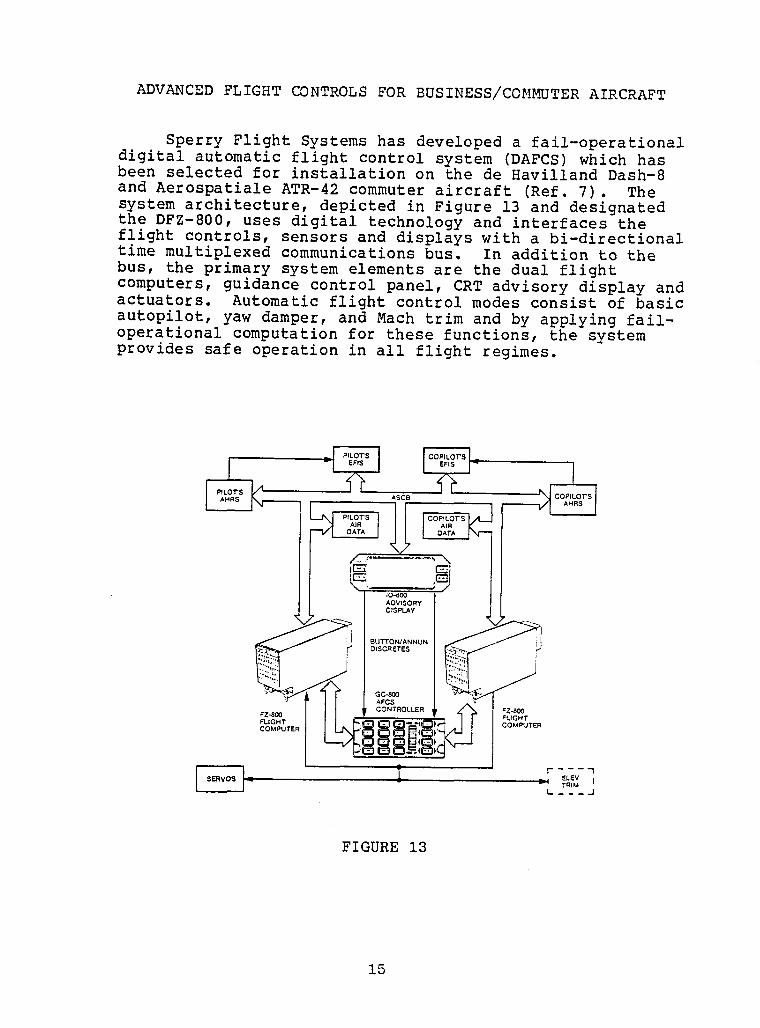
Sperry Flight Systems has developed a fail-operational idigital automatic flight control system (DAFCS) which hasbeen selected for installation on the de Havilland Dash-8and Aerospatiale ATR-42 commuter aircraft (Ref. 7). The isystem architecture, depicted in Figure 13 and designatedthe DFZ-800, uses digital technology and interfaces theflight controls, sensors and displays with a bi-directional •time multiplexed communications bus. In addition to the Ibus, the primary system elements are the dual flightcomputers, guidance control panel, CRT advisory display and I
actuators. Automatic flight control modes consist of basic •autopilot, yaw damper, and Mach trim and by applying fail-operational computation for these functions, the systemprovides safe operationin all flight regimes, i
w
I
+i III
1 IFZ-800 I
FZ-800 FLfGHTFLIGHT COMPUTERCOMPUTER
r------t i._! ELEV ITRIM
L.. _ _ _ -I
FIGURE 13 i
!I
15 |
i CH-53 E HELICOPTER
i The Sikorsky CH-53E was the first digital automaticflight control system (AFCS) in a production helicopter.Experimental versions of the vehicle contained analog
n circuitry but reliability, maintenance, and development/mission flexibility considerations favored a digitalimplementation which was first flight tested in 1977. While
I the CH-53E has mechanical primary control, the dual digitalAFCS includes the following systems and features: stabilityaugmentation; hover augmentation; a pitch bias actuator
i system giving the pilot positive longitudinal static stickstability; and a force augmentation system providinglongitudinal cyclic stick forces proportional to the
i maneuvering load factor at speeds above 60 knots. Althoughthe dual digital system is not strictly a flight criticalsystem, it is vital to effective helicopter operationsbecause the unaugmented system is difficult to fly under
I certain conditions. The autopilot portion of the AFCScontrols the long term flight path of the vehicle andsatisfies requirements for maintaining pressure altitude,
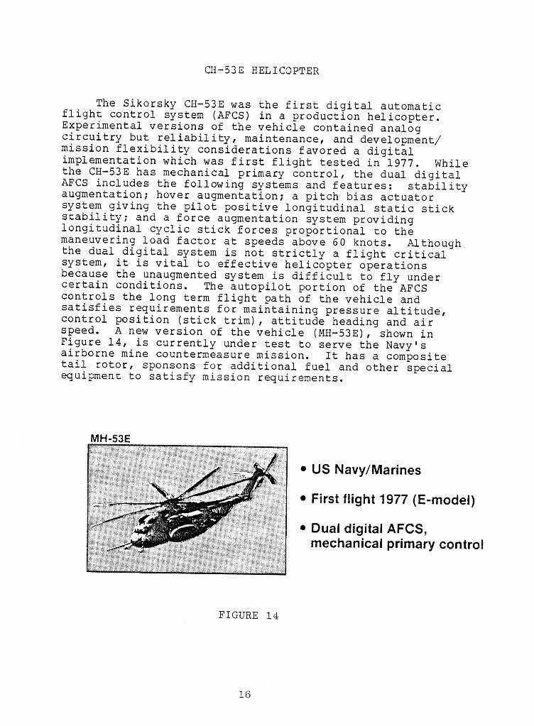
i control position (stick trim), attitude heading and airspeed. A new version of the vehicle (MH-53E), shown inFigure 14, is currently under test to serve the Navy's
i airborne mine countermeasure mission. It has a compositetail rotor, sponsons for additional fuel and other specialequipment to satisfy mission requirements.
!n MH-53E
i • US Navy/Marines• First flight 1977 (E-model)
I • Dual digital AFCS,
i mechanical primary control
!i FIGURE 14
II 16

!
AH-64A HELICOPTER I
mPictured in Figure 15, the Army's Advanced Attack i
Helicopter (AH-64A) is currently in production at Hugheswith delivery scheduled to start in February 1984. While iutilizing mechanical primary control, the flight control Bsystem features several pilot aids to reduce pilot work-load. These include three-axis short period stabilityaugmentation (SAS), three-axis maneuvering stability command iaugmentation (CAS), two-axis long-period attitude hold, lartificial feel in the longitudinal axis, turn coordination,flap control and a four axis fly-by-wire back-up control •system built by Sperry Flight Systems. While unusual for a mhelicopter, the AH-64A has full-span flaps in small fixedwings attached to the fuselage. The stub wings are needed •for mounting external stores but carry the disadvantage of |generating lift and, thus, absorbing part of the energy thatcould be (and during autorotation needs to be) stored in themain rotor. To circumvent this, the flaps automatically Hdeflect upwards during autorotation acting like spoilers to
i
destroy lift and deflect downwards like conventional flapsduring maneuvering operations to unload the main rotor and iavoid over-stressing it. |
AH-64A I
!• US Army (Hughes)
I
• In production (delivery i
early 1984) |
• Mechanical primary control,three axis CAS/SAS, four |axis FBW back-up control
I!
FIGURE 15 i
!
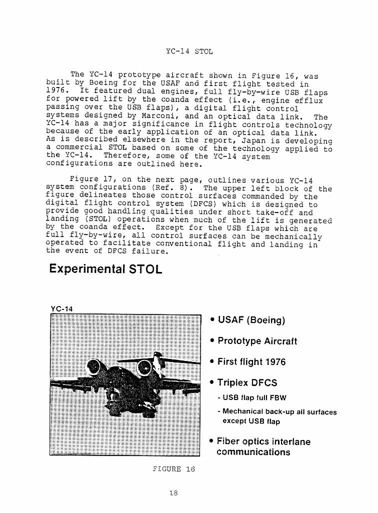
YC-14 STOL
The YC-14 prototype aircraft shown in Figure 16, wasbuilt by Boeing for the USAF and first flight tested in1976. It featured dual engines, full fly-by-wire USB flapsfor powered lift by the coanda effect (i.e., engine effluxpassing over the USB flaps), a digital flight controlsystems designed by Marconi, and an optical data link. TheYC-14 has a major significance in flight controls technologybecause of the early application of an optical data link.As is described elsewhere in the report, Japan is developinga commercial STOL based on some of the technology applied tothe YC-14. Therefore, some of the YC-14 systemconfigurations are outlined here.
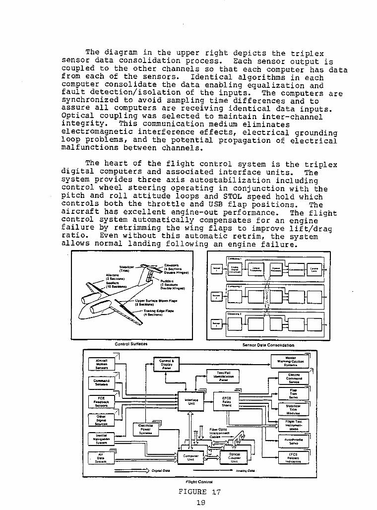
Figure 17, on the next page, outlines various YC-14system configurations (Ref. 8). The upper left block of thefigure delineates those control surfaces commanded by thedigital flight control system (DFCS) which is designed toprovide good handling qualities under short take-off andlanding (STOL) operations when much of the lift is generatedby the coanda effect. Except for the USB flaps which arefull fly-by-wire, all control surfaces can be mechanicallyoperated to facilitate conventional flight and landing inthe event of DFCS failure.
ExperimentalSTOL
YC-14
• USAF (Boeing)
• Prototype Aircraft
I • First flight 1976
i • Triplex DFCS- USB flap full FBW
I - Mechanical back-up all surfacesexcept USB flap
I • Fiber optics interlanecommunications
I FIGURE 16
I 18
II
The diagram in the upper right depicts the triplexsensor data consolidationprocess. Each sensor output iscoupled to the other channels so that each computer has data ifrom each of the sensors. Identicalalgorithmsin eachcomputer consolidatethe data enablingequalizationandfault detection/isolationof the inputs. The computersare isynchronizedto avoid sampling time differencesand to lassure all computersare receiving identicaldata inputs.Optical couplingwas selectedto maintain inter-channel mm
integrity. This communicationmedium eliminates melectromagneticinterferenceeffects, electricalgrounding
m
loop problems, and the potentialpropagationof electricalmalfunctionsbetween channels, i
mm
The heart of the flight control system is the triplexdigital computersand associatedinterfaceunits. The isystem provides three axis autostabilizationincluding mcontrol wheel steering operatingin conjunctionwith thepitch and roll attitudeloops and STOL speed hold which •controls both the throttle and USB flap positions. The iaircraft has excellentengine-outperformance. The flightcontrol system automaticallycompensatesfor an enginefailure by retrimmingthe wing flaps to improve lift/drag iratio. Even without this automatic retrim, the system
m
allows normal landing followingan engine failure.
!_ '.'_,_'2') I _'_..°.,. ',,': i
°-°--, ,-o m
Control Our/aces Sensor Data Consolidation
/ Test/Foil I _ £1eCt '"7
l?_ _ I ! ,,.°-TI •
( i° -, -n,_ 01_I_ Dlta ]i An_og Oaim-
FllcJht Control
FIGURE 17 m19
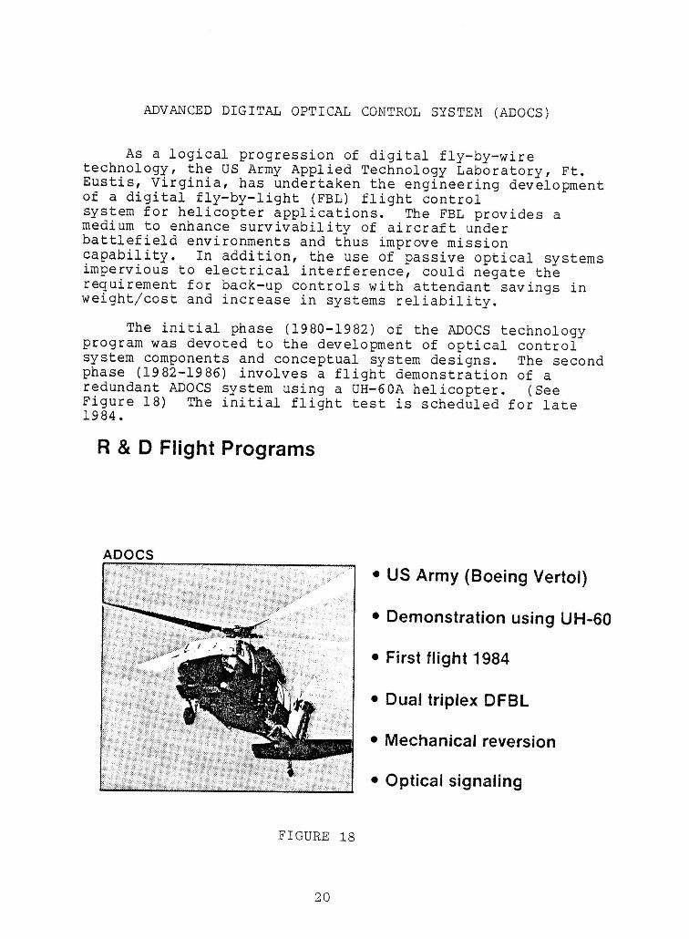
ADVANCED DIGITAL OPTICAL CONTROL SYSTEM (ADOCS)
AS a logical progression of digital fly-by-wiretechnology, the US Army Applied Technology Laboratory, Ft.Eustis, Virginia, has undertaken the engineering developmentof a digital fly-by-light (FBL) flight controlsystem for helicopter applications. The FBL provides amedium to enhance survivability of aircraft underbattlefield environments and thus improve missioncapability. In addition, the use of passive optical systemsimpervious to electrical interference, could negate therequirement for back-up controls with attendant savings inweight/cost and increase in systems reliability.
The initial phase (1980-1982) of the ADOCS technologyprogram was devoted to the development of optical controlsystem components and conceptual system designs. The secondphase (1982-1986) involves a flight demonstration of aredundant ADOCS system using a UH-60A helicopter. (SeeFigure 18) The initial flight test is scheduled for late1984.
R & D Flight Programs
ADOCS
• US Army (Boeing Vertol)
• Demonstration using LIH-60/
i • First flight 1984
i • Dual triplex DFBL• Mechanical reversion
I• Optical signaling
IFIGURE 18
II 20
Ii
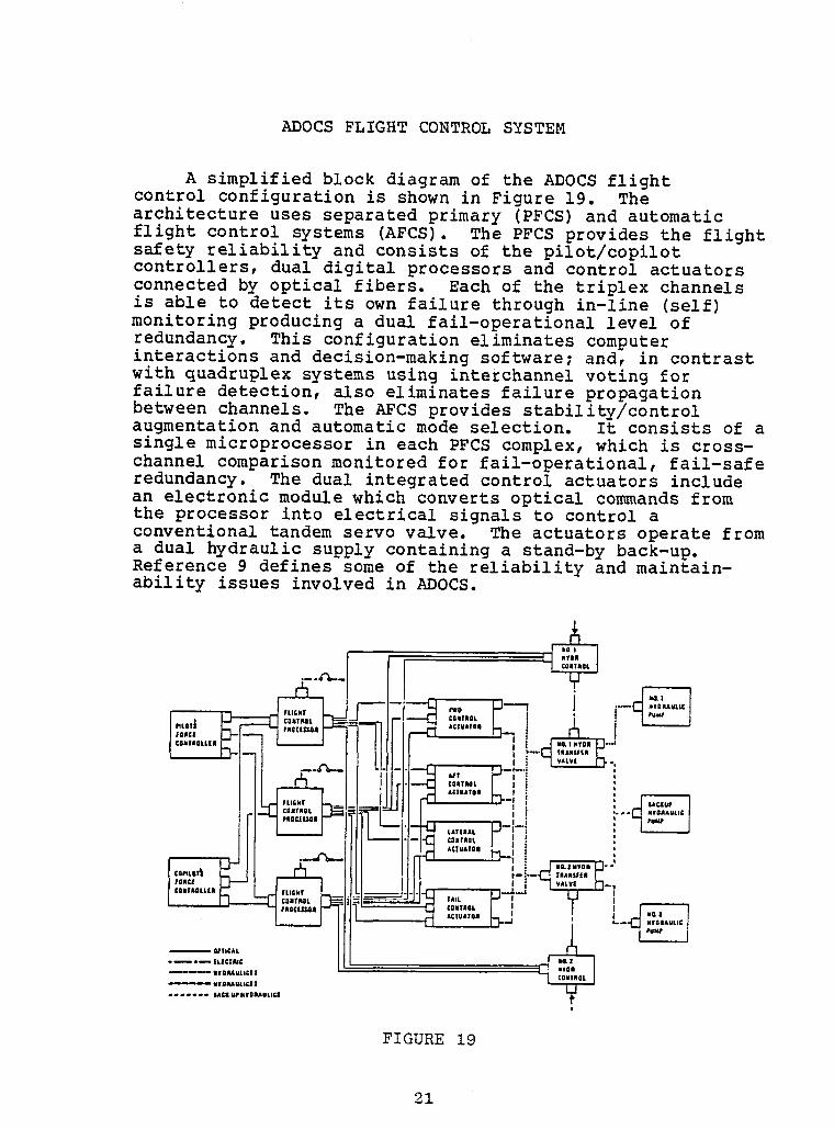
ADOCS FLIGHT CONTROL SYSTEMn
A simplified block diagram of the ADOCS flight ncontrol configuration is shown in Figure 19. Thearchitectureuses separatedprimary (PFCS)and automatic mflight control systems (AFCS). The PFCS provides the flight
iB
safety reliabilityand consists of the pilot/copilotcontrollers,dual digital processorsand control actuators iconnectedby optical fibers. Each of the triplex channelsis able to detect its own failure through in-line (self)monitoringproducing a dual fail-operationallevel of inredundancy. This configurationeliminatescomputer iinteractionsand decision-makingsoftware;and, in contrastwith quadruplexsystems using interchannelvoting for nfailure detection,also eliminatesfailure propagation ibetween channels. The AFCS provides stability/controlaugmentationand automaticmode selection. It consists of asingle microprocessorin each PFCS complex,which is cross- ichannel comparisonmonitored for fail-operational,fail-saferedundancy. The dual integratedcontrol actuators includean electronicmodule which convertsoptical commands from •the processor into electricalsignals to control aconventionaltandem servo valve. The actuatorsoperate froma dual hydraulicsupply containinga stand-by back-up, iReference9 defines some of the reliabilityand maintain- mability issues involved in ADOCS.
€ 'Ii._ cll,.Rat / t : t I ,u_ 1
INIJ-_:::::'"5:--H-, _-,-!
A " I_._ €IUAIOA _ | • i iP' '_'II : J,,_,_, II f ...._L, ,,_,._., ,, _t,::_"'"l
tAT'IAL F--I I } ,-ka _o.,,o,/ I I : n
I.-_ AClUATon L-- ; ; iII I I _ v,lLve __,
__.L._,,I I---J-J-_,... _ , --O-'--',C] CO.tmOL/ I _ I I
• _ *_ |LICIIIUC
m---Z:::X;::',:: ' "°'n
FIGURE 19 i
MILITARY ADVANCED ROTORCRAFT DEVELOPMENTS
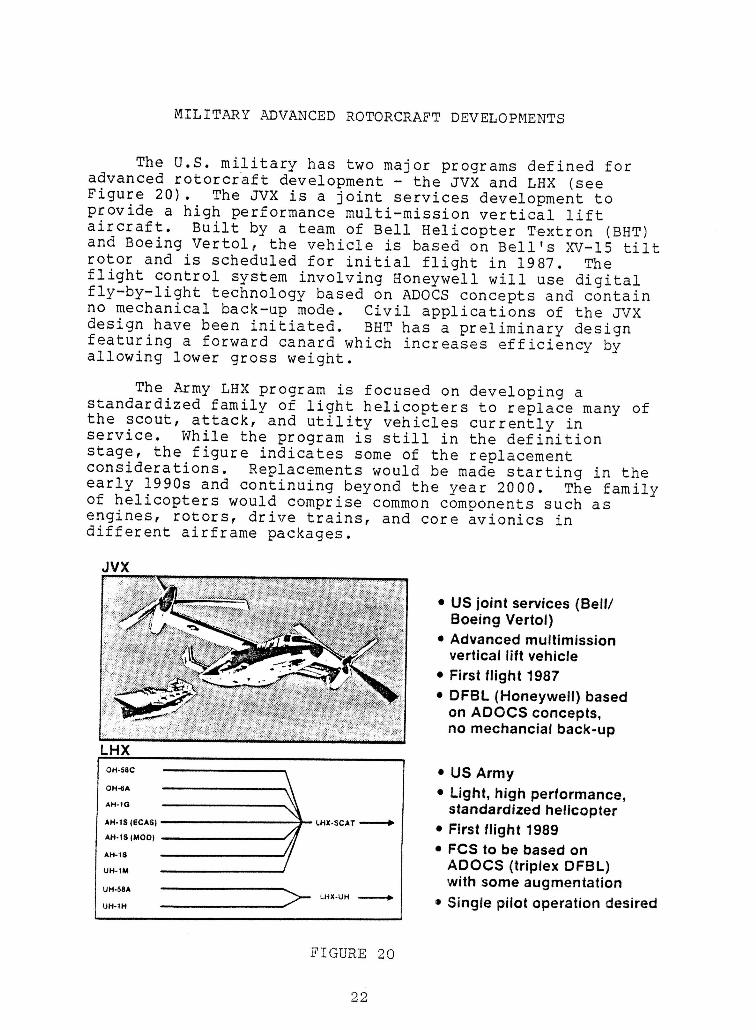
The U.S. military has two major programs defined foradvanced rotorcraft development - the JVX and LHX (seeFigure 20). The JVX is a joint services development toprovide a high performance multi-mission vertical liftaircraft. Built by a team of Bell Helicopter Textron (BHT)and Boeing Vertol, the vehicle is based on Bell's XV-15 tiltrotor and is scheduled for initial flight in 1987. Theflight control system involving Honeywell will use digitalfly-by-light technology based on ADOCS concepts and containno mechanical back-up mode. Civil applications of the JVXdesign have been initiated. BHT has a preliminary designfeaturing a forward canard which increases efficiency byallowing lower gross weight.
The Army LHX program is focused on developing astandardized family of light helicopters to replace many ofthe scout, attack, and utility vehicles currently inservice. While the program is still in the definitionstage, the figure indicates some of the replacementconsiderations. Replacements would be made starting in theearly 1990s and continuing beyond the year 2000. The familyof helicopters would comprise common components such asengines, rotors, drive trains, and core avionics indifferent airframe packages.
JVX
• US joint services (Bell/Boeing Vertol)
• Advanced multimissionvertical lift vehicle
I • First flight 1987• DFBL (Honeywell) based
on ADOCS concepts,
no mechancial back-upLHX
I o...c ! • US Army
0.4. • Light, high performance,..-,_ standardized helicopter
A.._s_c.s_ ,. _.x.SCAT------* • First flight 1989AH-tS(MOO)• FCS to be based on
•.-,s ADOCS (triplex DFBL)
i UH-1M with some augmentationu,.,, _ _,x.uH_ • Single pilot operation desiredUH-1H
FIGURE 20
l 22
!LHX PLANS I
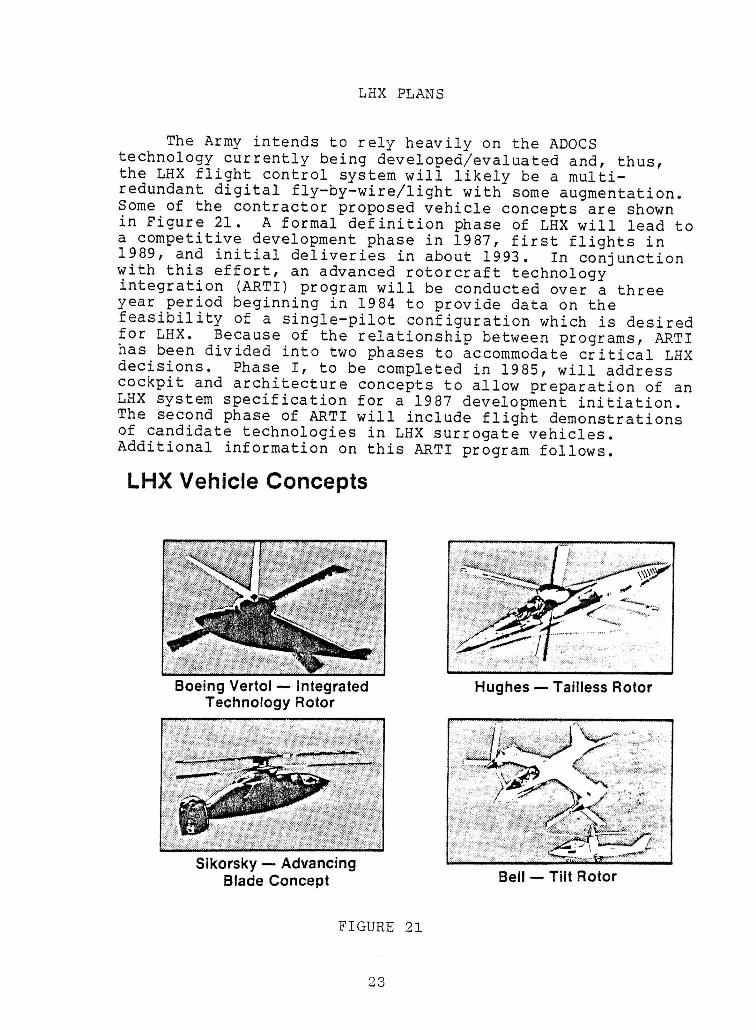
The Army intends to rely heavily on the ADOCS Htechnology currently being developed/evaluated and, thus,the LHX flight control system will likely be a multi-redundant digital fly-by-wire/light with some augmentation. HSome of the contractor proposed vehicle concepts are shownin Figure 21. A formal definition phase of LHX will lead toa competitive development phase in 1987, first flights in i1989, and initial deliveries in about 1993. In conjunctionwith this effort, an advanced rotorcraft technologyintegration (ARTI) program will be conducted over a three •year period beginning in 1984 to provide data on the Hfeasibility of a single-pilot configuration which is desiredfor LHX. Because of the relationship between programs, ARTI m
has been divided into two phases to accommodate critical LHXdecisions. Phase I, to be completed in 1985, will address
m
cockpit and architecture concepts to allow preparation of anLHX system specification for a 1987 development initiation.The second phase of ARTI will include flight demonstrationsof candidate technologies in LHX surrogate vehicles.
Additional information on this ARTI program follows. H
LHX Vehicle Concepts
!!!n
BoeingVertol -- Integrated Hughes-- TaillessRotor ==Technology Rotor
I!!
Sikorsky -- Advancing
Blade Concept Bell -- Tilt Rotor N
FIGURE 21 I
!i ADVANCED ROTORCRAFT INTEGRATION PROGRAM (ARTI)
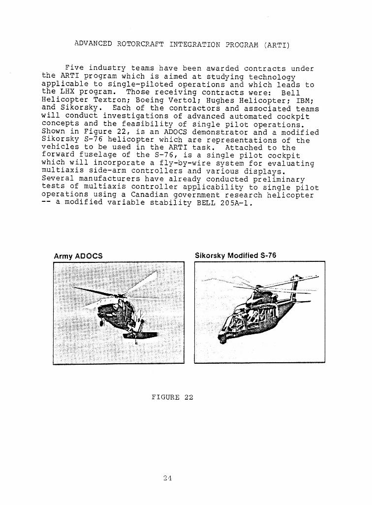
I Five industry teams have been awarded contracts underthe ARTI program which is aimed at studying technologyapplicable to single-piloted operations and which leads to
I the LHX program. Those receiving contracts were: BellHelicopter Textron; Boeing Vertol; Hughes Helicopter; IBM;and Sikorsky. Each of the contractors and associated teams
i will conduct investigations of advanced automated cockpitconcepts and the feasibility of single pilot operations.Shown in Figure 22, is an ADOCS demonstrator and a modifiedSikorsky S-76 helicopter which are representations of the
i vehicles to be used in the ARTI task. Attached to theforward fuselage of the S-76, is a single pilot cockpitwhich will incorporate a fly-by-wire system for evaluating
I multiaxis side-arm controllers and various displays.Several manufacturers have already conducted preliminarytests of multiaxis controller applicability to single pilot
i operations using a Canadian government research helicopter-- a modified variable stability BELL 205A-I.
!
I Army ADOCS Sikorsky Modified S-76i
!!
!FIGURE 22
I!!
IADVANCED HELICOPTER IMPROVEMENT PROGRAM (AHIP) i
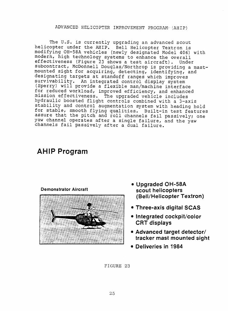
The U.S. is currently upgrading an advanced scout ihelicopter under the AHIP. Bell Helicopter Textron ismodifying OH-58A vehicles (newly designated Model 406) withmodern, high technology systems to enhance the overall •effectiveness (Figure 23 shows a test aircraft). Under
subcontract, McDonnell Douglas/Northrop is providing a mast-mounted sight for acquiring, detecting, identifying, and •designating targets at standoff ranges which improves |survivability. An integrated control display system(Sperry) will provide a flexible man/machine interfacefor reduced workload, improved efficiency, and enhanced imission effectiveness. The upgraded vehicle includes i
hydraulic boosted flight controls combined with a 3-axis
stability and control augmentation system with heading hold ifor stable, smooth flying qualities. Built-in test featuresassure that the pitch and roll channels fail passively; oneyaw channel operates after a single failure, and the yaw •channels fail passively after a dual failure. m
IAHIP Program |
• Upgraded OH-58ADemonstrator Aircraft Scout helicopters i
(Bell/Helicopter Textron)
• Three-axis digital SCAS i
• Integrated cockpit/colorCRT displays i
• Advanced target detector/ •tracker mast mounted sight i
• Deliveries in 1984I
FIGURE 23 i
I
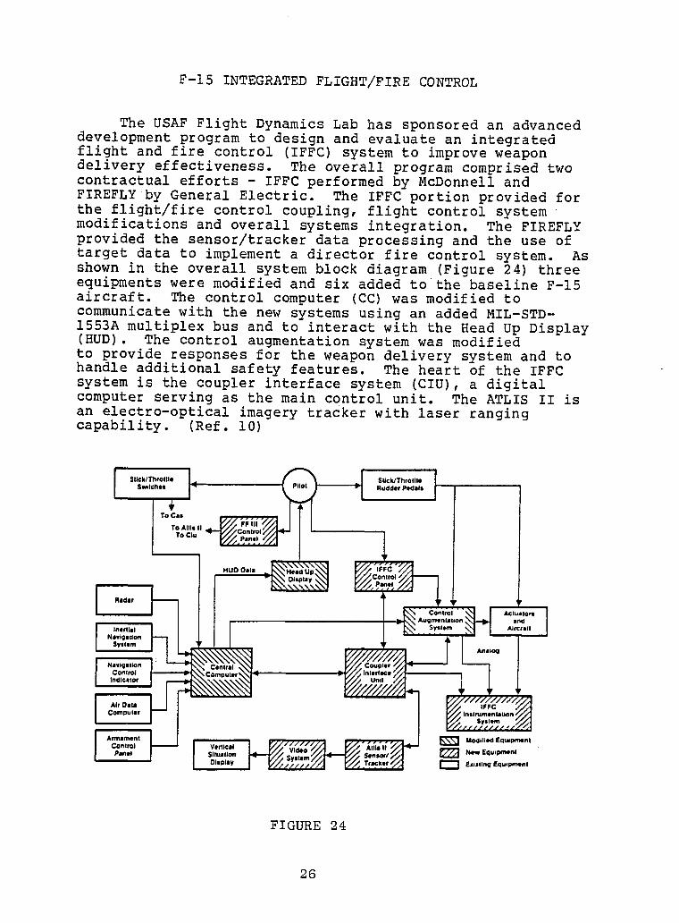
II F-15 INTEGRATED FLIGHT/FIRE CONTROL
I The USAF Flight Dynamics Lab has sponsored an advanceddevelopment program to design and evaluate an integratedflight and fire control (IFFC) system to improve weapon
i delivery effectiveness. The overall program comprised twocontractual efforts - IFFC performed by McDonnell andFIREFLY by General Electric. The IFFC portion provided forthe flight/fire control coupling, flight control system
I systems integration. The FIREFLYmodifications and overall
provided the sensor/tracker data processing and the use oftarget data to implement a director fire control system. As
I shown in the overall system block diagram (Figure 24) threeequipments were modified and six added to the baseline F-15aircraft. The control computer (CC) was modified to
I communicate with the new systems using an added MIL-STD-1553A multiplex bus and to interact with the Head Up Display(HUD). The control augmentation system was modified
i to provide responses for the weapon delivery system and tohandle additional safety features. The heart of the IFFCsystem is the coupler interface system (CIO), a digitalcomputer serving as the main control unit. The ATLIS II is
I an electro-optical imagery tracker with laser rangingcapability. (Ref. i0)
!SUck/ThroWe I SUck/Throttle I
$wJichel _ Rudder Pedals
| ' ,ToCa"
To AIllll |1To C|u
i HUD Oale
I I Radar
NIv|_I111 Olrl
NIIVlgllllOtl _ • Arll6og
I irtlrControl _C_ nm_ -_ 1
I '°'"'0'l Air Olle
Compular
$ylle/11
Control VerticalPlnel S|lUal)oll _ New fqulpmilnl
OIIpley [_] Existing Equlwnenl
!I FIGURE 24
| 26
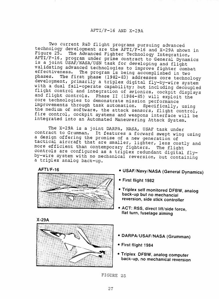
I IAFTI/F-16 AND X-29A
Two current R&D flight programs pursuing advanced itechnology development are the AFTI/F-16 and X-29A shown in
Figure 25. The Advanced Fighter Technology Integration, iAFTI/F-16, program under prime contract to General Dynamicsis a joint USAF/NASA/USN task for developing and flight
validating advanced technologies to improve fighter combat Ieffectiveness. The program is being accomplished in twophases. The first phase (1982-83) addresses core technology
development, primarily a triplex digital fly-by-wire system iwith a dual fail-operate capability; but including decoupledflight control and integration of avionics, cockpit displaysand flight controls. Phase II (1984-85) will exploit thecore technologies to demonstrate mission performance Iimprovements through task automation. Specifically, usingthe medium of software, the attack sensors, flight control,
fire control, cockpit systems and weapons interface will be iintegrated into an Automated Maneuvering Attack System.
The X-29A is a joint DARPA, NASA, USAF task under icontract to Grumman. It features a forward swept wing usinga design offering the promise of a new generation oftactical aircraft that are smaller, lighter, less costly and
more efficient than contemporary fighters. The flight Icontrols are configured as a triplex redundant digital fly-by-wire system with no mechanical reversion, but containing
a triplex analog back-up, i
AFTI/F-16 • USAF/Navy/NASA(GeneralDynamics)
• Firstflight 1982 I
• Triplex selfmonitoredDFBW, analogback-upbut no mechancial !reversion,sidestickcontroller
•ACT: RSS, direct lift/sideforce, Iflat turn, fuselageaiming
X-29A I
• DARPA/USAF/NASA(Grumman) •
• Firstflight 1984
•Triplex DFBW,analogcomputer iback-up,no mechanicalreversion
FIGURE 25 I
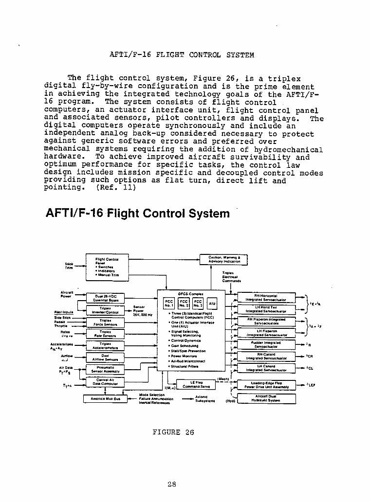
I AFTI/F-16 FLIGHT CONTROL SYSTEM
I The flight control system, Figure 26, is a triplexdigital fly-by-wire configuration and is the prime element
I in achieving the integrated technology goals of the AFTI/F-16 program. The system consists of flight controlcomputers,an actuator interfaceunit, flight control panel
and associatedsensors,pilot controllersand displays. Thedigital computersoperate synchronouslyand include anindependentanalog back-up considerednecessary to protectagainst generic softwareerrors and preferred over
mechanical systems requiring the addition of hydromechanicalhardware. To achieve improved aircraftsurvivabilityandoptimum performancefor specifictasks, the control law
design includesmission specific and decoupledcontrol modesprovidingsuch options as flat turn, direct lift andpointing. (Ref.ii)
!AFTi/F-16 Flight ControlSystem
II C•ullon, Wilming &
IdUCmk ,_ Flight Coiltrol Ad_iory IOdicIIIOn
• SwiIc_I
I • InllicltO#l l Triplall
• Inuit Till liltrllCommindl
OFCS ComplIi _ RH H411illoniill t)I _rll_ EslintlII 8ulls tf +_A
Tripiez | Sef%sO_r LH HoflZ 1111Intil_rlle¢_ Sefiol_ill•to¢IDIIo • Inverler/Control Power * Three (3) IdenliClll Flight26V, 800 Hi
lriplel -- * One 11) lctullol I.ladicl SerioictliilOrl tl ! IF
Riles Triplex * SlcJnlll Selecting, LH Flaptlron• I ,W Rile SenlOli Voiing Monitoring Integriiliti Sel_o_tulfor
• Conifoi Oy..... i_ Rudd41, ,ntelJriied t ''-li _RA==I,O,..on.----_ T.pla. L •G.,.s_.._i,ng =_ S...o=,=._. /
AliiIow O_il • POWer _it_ Inl_rltilt Solrioilcliiiltor._1 Air/lOWSensors • AlI-Rud Inlaiconriict
I (Mech)__Cimtvel A_r LE Flap -- -- Lliiding-Eil¢lle Flap _LEF
TT.a Dim COmliltlar I( Command Serio pOwolrDrive Unit AiliimDiy
t , t Mode Selection Avionic \ AlrCrIII
I FIGURE 26
II 28
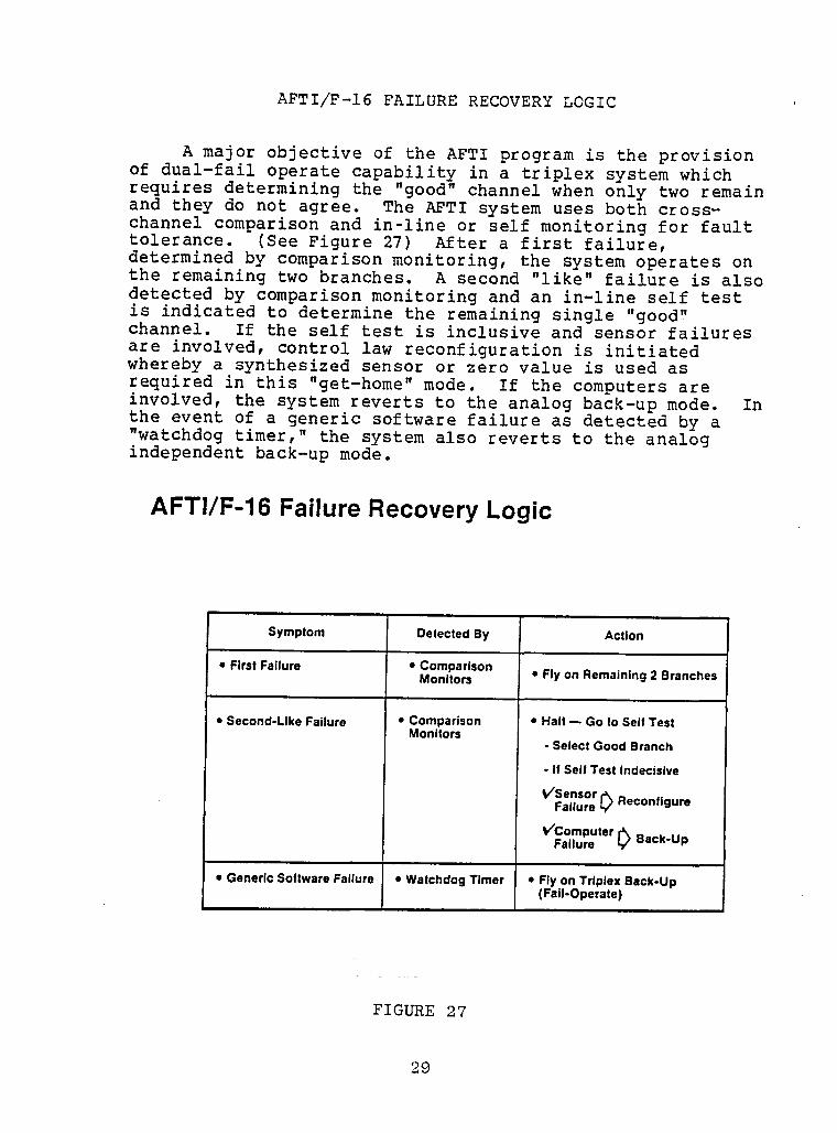
IAFTI/F-16 FAILURE RECOVERY LOGIC i
i
A major objective of the AFTI program is the provision iof dual-failoperate capabilityin a triplex system whichrequires determiningthe "good" channel when only two remainand they do not agree. The AFTI system uses both cross- nchannel comparisonand in-line or self monitoringfor fault |tolerance. (See Figure 27) After a first failure,determinedby comparisonmonitoring,the system operates on •the remainingtwo branches. A second "like"failure is also idetected by comparisonmonitoringand an in-line self testis indicatedto determinethe remainingsingle "good"channel. If the self test is inclusiveand sensor failuresare involved, control law reconfigurationis initiatedwhereby a synthesizedsensor or zero value is used asrequired in this "get-home"mode. If the computersare ninvolved,the system reverts to the analog back-up mode. Inthe event of a generic software failure as detected by a"watchdogtimer," the system also reverts to the analogindependentback-up mode. l
AFTl/F-16 Failure Recovery Logic |
I•' ISymptom Detected By Action
•First Failure •Comparison
Monitors • Flyon Remaining2 Branches i
• Second-LikeFailure • Comparison • Halt -- Go to Self TestMonitors
- Select Good Branch n
. if self Test Indecisive
VSensor r'X mFailure L/Recontlgure
V'ComputerFailure [_ Back-Up !
• Generic Software Failure • Watchdog Timer • Fly on Triplex Back-Up
(Fail-Operate) i
FIGURE 27 n
I
I X-29A FLIGHT CONTROL SYSTEM
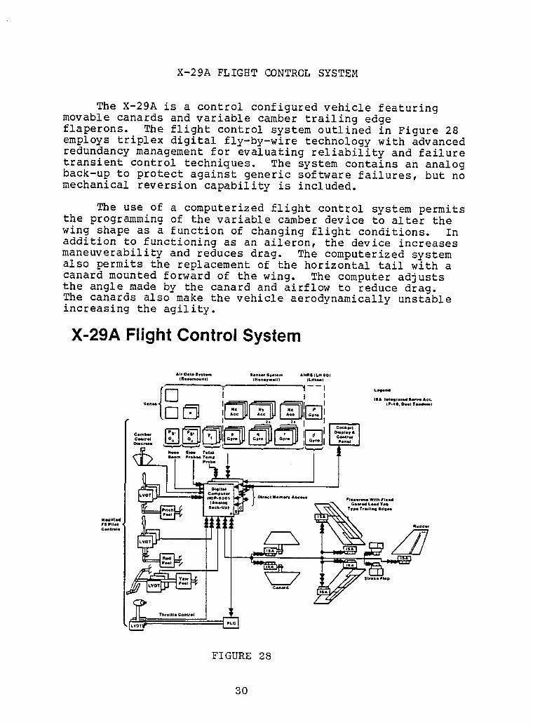
I The X-29A is a control configured vehicle featuringmovable canards and variable camber trailing edge
i flaperons. The flight contro! system outlined in Figure 28employs triplex digital fly-by-wire technology with advancedredundancy management for evaluating reliability and failuretransient control techniques. The system contains an analog
I back-up to protect against generic software failures, butno
mechanical reversion capability is included.
I The use of a computerized flight control system permitsthe programming of the variable camber device to alter the
wing shape as a function of changing flight conditions. In
i addition to functioning as an aileron, the device increasesmaneuverability and reduces drag. The computerized systemalso permits the replacement of the horizontal tail with a
i canard mounted forward of the wing. The computer adjuststhe angle made by the canard and airflow to reduce drag.The canards also make the vehicle aerodynamically unstableincreasing the agility.
I X-29A Flight ControlSystem
!Air Oeta Svetem SoneeqSyetem AHR$ (LN eO)
(Ploa_ountJ (Nona_we6_) (Litton)
I /I I I I
Boons Probes Temp
/
I =
2,.o,..........|
I FIGURE 28
I 30
I|
ADVANCED TACTICAL FIGHTER (ATF) •
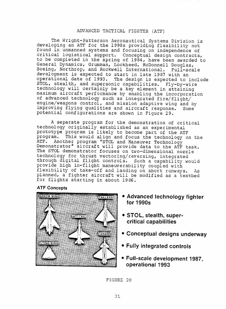
The Wright-Patterson Aeronautical Systems Division is •developing an ATF for the 1990s providing flexibility notfound in unmanned systems and focusing on independence ofcritical logistical support. Conceptual design contracts, nto be completed in the spring of 1984, have been awarded to iGeneral Dynamics, Grumman, Lockheed, McDonnell Douglas,Boeing, Northrop, and Rockwell International. Full-scaledevelopment is expected to start in late 1987 with an Ioperational date of 1993. The design is expected to includeSTOL, stealth, and supersonic capabilities. Fly-by-wiretechnology will certainly be a key element in attaining •maximum aircraft performance by enabling the incorporationof advanced technology such as integrated fire/flight/engine/weapons control, and mission adaptive wing and by •improving flying qualities and aircraft response. Some Upotential configurations are shown in Figure 29.
A separate program for the demonstration of critical itechnology originally established as an experimental
m
prototype program is likely to become part of the ATFprogram. This would align and focus the technology on the iATF. Another program "STOL and Maneuver Technology lDemonstrator" aircraft will provide data to the ATF task.The STOL demonstrator focuses on two-dimensional nozzle •technology for thrust vectoring/reversing, integrated Ithrough digital flight controls. Such a capability wouldprovide high in-flight maneuverability coupled withflexibility of take-off and landing on short runways. As nplanned, a fighter aircraft will be modified as a testbed l
for flights starting in about 1986.
ATF Concepts n
• Advanced technology fighterfor 1990s n
• STOL, stealth, super-critical capabilities i
designs underway iConceptual
• Fully integrated controls iIIII
• Full-scale development 1987,
operational 1993 i
FIGURE 29 I
!l OTHER U.S. ACTIVITIES
l During the conduct of the survey, several othertechnical programs were identified which directly orindirectly relate to flight crucial flight control systems.
I These are briefly outlined below.
HiMAT- The highly maneuverable aircraft technology
I program was established as a joint NASA/USAF projectto develop an advanced remotely piloted research vehicle forin-flight evaluation of several advanced technology concepts
l and test techniques beyond those considered safe for normalpiloted test operations. Among the technologiesincorporated and investigated in the program are digital
i flight controls, close-coupled canard configurations,aeroelastic tailoring, advanced structures/aerodynamics andintegrated propulsion control. In addition, the program hasgenerated systems and test techniques providing valuable
I test aids and tools for further research and operationalvehicle applications.
l DEEC/HIDEC- The digital electronic engine control isa full authority digital engine control system designed toimprove engine efficiency, performance, and operations. It
includes the capability for providing engine health statusinformation and for detecting/accommodating real-timefailures. The DEEC consists of a single channel controllerwith selective redundancy and an integral hydromechanical
I back-up control. The system has been successfully flighttested by NASA using a F-15 testbed aircraft. HIDEC, HighlyIntegrated Digital Engine Control, is an extension of DEEC
I coupling in the flight control system.ACEE/L-1011 - As part of NASA's Aircraft Energy
i Efficiency (ACEE) program, Lockheed developed and flighttested a maneuver load alleviation system that allowedincorporation of a higher aspect wing without majorstructural changes. The L-1011/500 was certified with such
I a system in 1980 and is now in commercial service.passenger
In 1983, a limited authority pitch active control system(PACS) was developed and evaluated on a wide-body L-1011
I transport. The test results indicated that the PACS willmaintain good aircraft handling qualities for relaxed staticstability flight conditions. The implementation of such
I technology necessitates the assurance of appropriate systemarchitecture and reliability to make hazardous failuresextremely improbable.
I MISSION ADAPTIVE WING (MAW) - The AFTI/F-III aircraftwill serve as a testbed for evaluating the MAW. The winghas no conventional flaps, slats, ailerons, or spoilers but
I changes shape with varying flight conditions by using
l Z2
!!
variable camber mechanics coupled to a digital flightcontrol system. Flight tests of the joint NASA/USAF projectare scheduledto start in the summer of 1984 and continuefor two years.
R&M INITIATIVE- The Flight Controls Division of AFWAL •has started a new controls technologyactivity to improve |reliabilityand maintainabilityof flight control systems bytwo orders of magnitude for the ATF. The program is to nexploit the inherent
redundancyof ATF by fully utilizing Hthe multiple control surfaces to reconfigureafter failuresand use of expert system technologyfor automatic
maintenance diagnostics. NIAPSA- The objectiveof the integratedairframe/
propulsioncontrol system architecturesstudy sponsoredby •NASA is to define and evaluate candidatecontrol systemsarchitecturesbest suited for a high performanceaircraft ofthe 1990s with major airframe/propulsionsystem coupling. •Two teams were funded for this study: Lockheed - California |Co., Honeywell and Pratt & Whitney; and, Boeing MilitaryAirplane Co., and Bendix Flight Systems Division.
DMICS- AFWAL is sponsoringtwo studies to developdesign methods for integratedcontrol systems (DMICS);one ateam of Northrop,Systems Control Technologyand the GeneralElectric Company; the other of General Dynamics, Pratt &Whitney, Honeywelland Hamilton Standard. Each team isconductingthe study to develop a control designmethod for •functionalintegrationof flight and propulsioncontrols. |
TRANSATMOSPHERICVEHICLE (TAV)- Under USAF nsponsorship,conceptualstudies are being conductedon a TAV •for providingquick-reaction,global mission capabilities. n
The aerodynamicallyconfiguredvehicle would be capable oftake off from military airfields (possiblyvertically),propel itself into suborbitalflight and return to theatmospherefor conventionalflight operations. Advancedflight control systems developmentwould be among the key •technologiesrequired. Continuedstudies and planning mactivitieswill provide the basis for a 1988 decision on
prototypedevelopment. N
!!!
IIIIIIIII
FOREIGN AIRCRAFT SYSTEMS!!!!!!!!!
34
I

IIIIIIIIIIIIIIIIIII
IIi JA-37 AND AIRBUS A-310
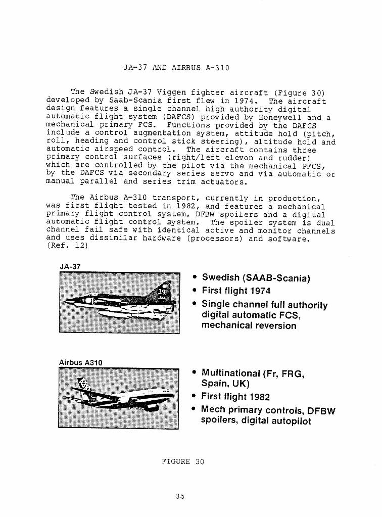
i The Swedish JA-37 Viggen fighter aircraft (Figure 30)developed by Saab-Scania first flew in 1974. The aircraft
design features a single channel high authority digitalautomatic flight system (DAFCS) provided by Honeywell and a
i mechanical primary FCS. Functions theprovided by DAFCS
include a control augmentation system, attitude hold (pitch,roll, heading and control stick steering), altitude hold and
i automatic airspeed control. The aircraft contains threeprimary control surfaces (right/left elevon and rudder)which are controlled by the pilot via the mechanical PFCS,
i by the DAFCS via secondary series servo and via automatic ormanual parallel and series trim actuators.
i The Airbus A-310 transport, currently in production,was first flight tested in 1982, and features a mechanical
primary flight control system, DFBW spoilers and a digitalautomatic flight control system. The spoiler system is dual
i channel fail safe with identical active and monitor channelsand uses dissimilar hardware (processors) and software.(Ref. 12)
n JA-37
• Swedish (SAAB-Scania)I • First flight 1974
• Single channel full authorityi digital automatic FCS,
mechanical reversion
!I Airbus A310 • Multinational (Fr, FRG,
Spain, UK)i • First flight 1982
• Mech primary controls, DFBWU spoilers, digital autopilot
IFIGURE 30
iI 35
I
IAIRBUS A-320
m
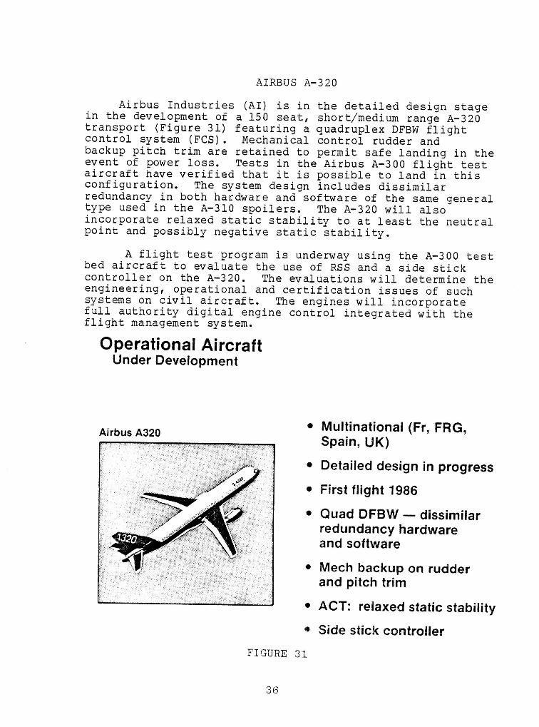
Airbus Industries (AI) is in the detailed design stage iin the development of a 150 seat, short/medium range A-320transport (Figure 31) featuring a quadruplex DFBW flight ncontrol system (FCS). Mechanical control rudder andbackup pitch trim are retained to permit safe landing in theevent of power loss. Tests in the Airbus A-300 flight test naircraft have verified that it is possible to land in this Bconfiguration. The system design includes dissimilarredundancy in both hardware and software of the same general i
type used in the A-310 spoilers. The A-320 will also •incorporate relaxed static stability to at least the neutral
u
point and possibly negative static stability.
A flight test program is underway using the A-300 test Ubed aircraft to evaluate the use of RSS and a side stick
controller on the A-320. The evaluations will determine the •engineering, operational and certification issues of such msystems on civil aircraft. The engines will incorporatefull authority digital engine control integrated with the •flight management system. i
Operational AircraftUnder Development i
I• Multinational (Fr, FRG, nAirbus A320
Spain, UK) i
• Detailed design in progress n• First flight 1986
• Quad DFBW --dissimilar iredundancy hardware
w
and software i• Mech backup on rudder
and pitch trim II
• ACT: relaxed static stabilityn
• Side stick controller i
FIGURE 31 i
I
II A-320 DFBW SYSTEM
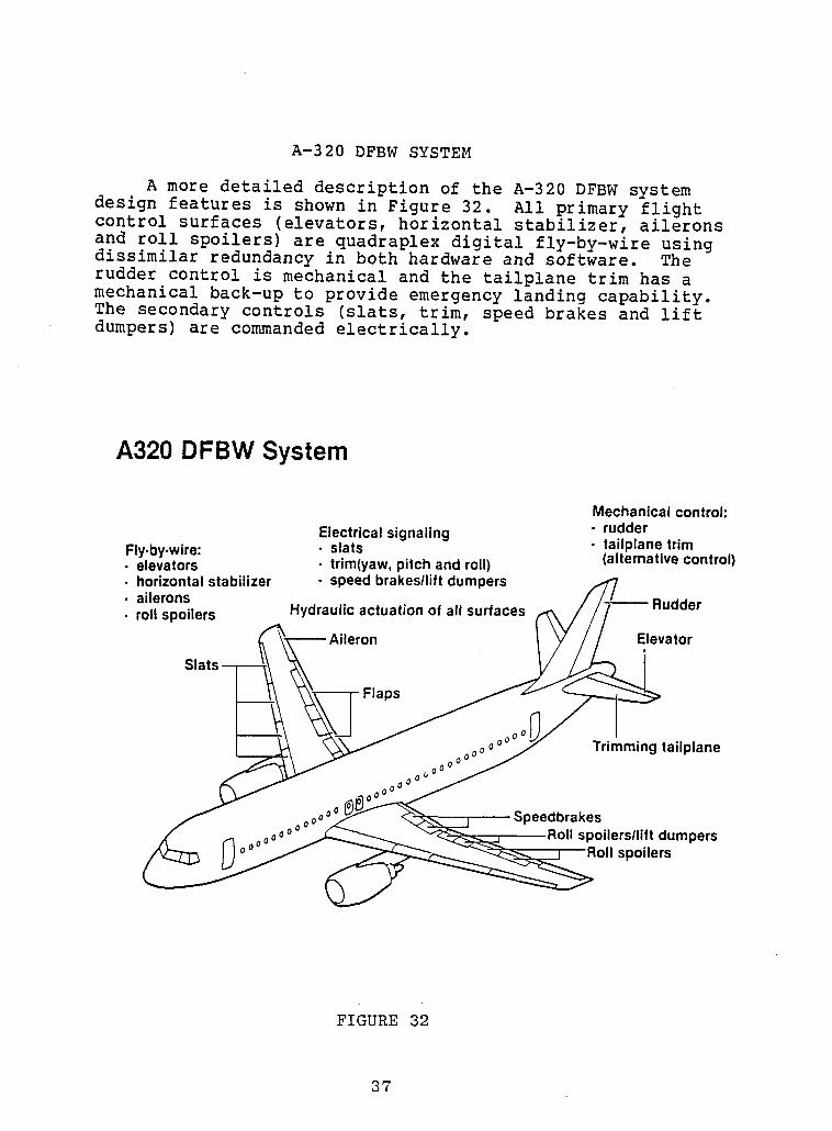
A more detailed description of the A-320 DFBW system
i design features is shown in Figure 32. All primary flightcontrol surfaces (elevators, horizontal stabilizer, ailerons
and roll spoilers) are quadraplex digital fly-by-wire usingdissimilar redundancy in both hardware and software. The
I mechanical and the tailplane trim has arudder control is
mechanical back-up to provide emergency landing capability.The secondary controls (slats, trim, speed brakes and lift
I dumpers) are commandedelectrically.
III A320 DFBW System
I Mechanical control:Electrical signaling - rudder
Fly.by-wire: • slats • tailplane trim
I elevators • trim(yaw,pitch and (alternative control)roll)I
- horizontalstabilizer • speedbrakes/lift dumpers• ailerons Rudder
I • roll spoilers Hydraulic actuation of all surfaces.=ron Elevator
i Slats )S
I Trimming taiiplane
_eedbrakesspoilers/lift dumpers
I _ spoilers
III FIGURE 32
I 37
II
AIRBUS INDUSTRIES FLIGHT CONTROL SYSTEM EVOLUTION l
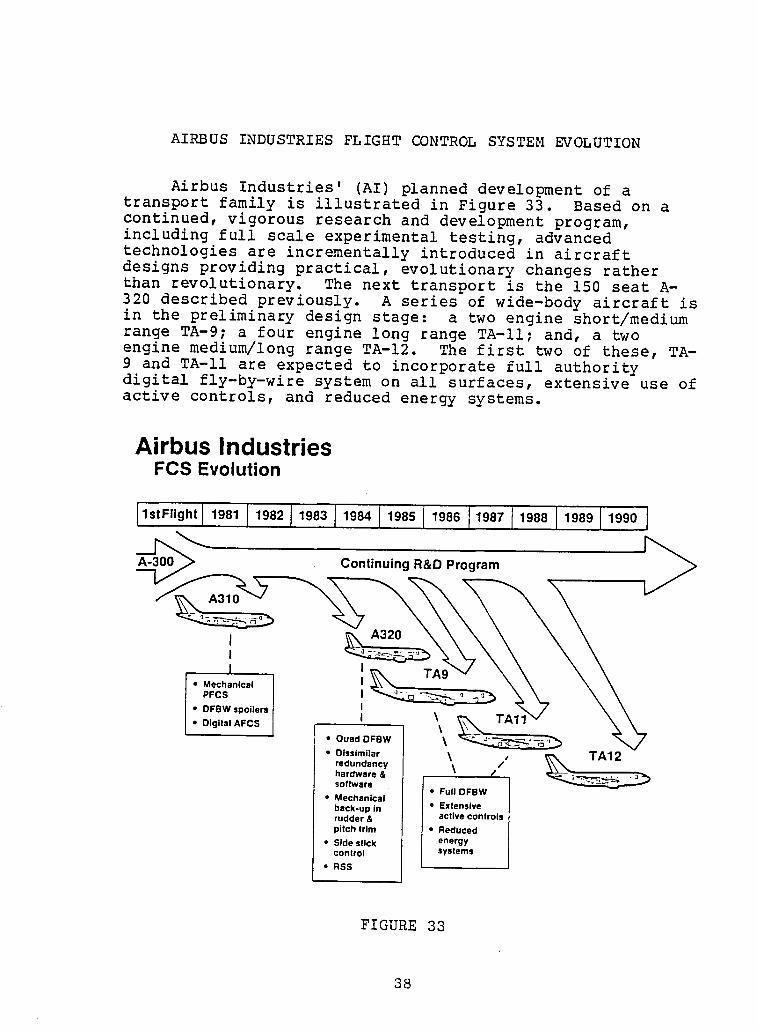
Airbus Industries' (AI) planned development of a ltransport family is illustrated in Figure 33. Based on a |continued, vigorous research and development program,including full scale experimental testing, advanced itechnologies are incrementally introduced in aircraft idesigns providing practical, evolutionary changes ratherthan revolutionary• The next transport is the 150 seat A-320 described previously. A series of wide-body aircraft is iin the preliminary design stage: a two engine short/medium 1
range TA-9; a four engine long range TA-II; and, a twoengine medium/long range TA-12. The first two of these, TA- l9 and TA-II are expected to incorporate full authority Udigital fly-by-wire system on all surfaces, extensive use of
active controls, and reduced energy systems. I
Airbus IndustriesFCS Evolution l
I"tF"gh' "O"!"O' J"08310.",00'0 01'0"110 110',000 ICon,,ou,ngO OProgrom!
I ._ A320 I
• Mechanical I ,L,____
PFCS I
• DFBW spoilers II I• Digital AFCS \_t
• Quad DFBW \
• Dissimilar \ / __ TA12redundancy _ " 1hardware &software • Full DFBW
• Mechanicalback-up in • Extensiverudder & active controls •pitch trim • Reduced I• Side stick energycontrol systems
• RSS I
FIGURE 33 I
TORNADO AND MIRAGE
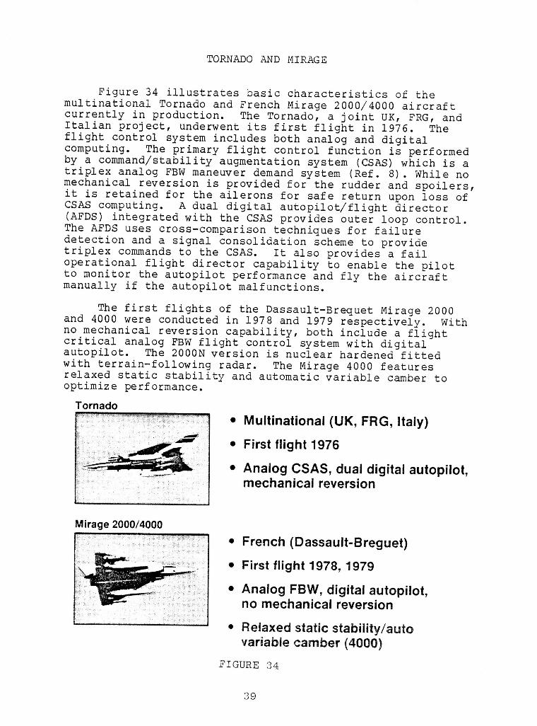
Figure 34 illustrates basic characteristics of themultinational Tornado and French Mirage 2000/4000 aircraftcurrently in production. The Tornado, a joint OK, FRG, andItalian project, underwent its first flight in 1976. Theflight control system includes both analog and digitalcomputing. The primary flight control function is performedby a command/stability augmentation system (CSAS) which is atriplex analog FBW maneuver demand system (Ref. 8). While nomechanical reversion is provided for the rudder and spoilers,it is retained for the ailerons for safe return upon loss ofCSAS computing. A dual digital autopilot/flight director(AFDS) integrated with the CSAS provides outer loop control.The AFDS uses cross-comparison techniques for failuredetection and a signal consolidation scheme to providetriplex commands to the CSAS. It also provides a failoperational flight director capability to enable the pilotto monitor the autopilot performance and fly the aircraftmanually if the autopilot malfunctions.
The first flights of the Dassault-Brequet Mirage 2000and 4000 were conducted in 1978 and 1979 respectively. Withno mechanical reversion capability, both include a flightcritical analog FBW flight control system with digitalautopilot. The 2000N version is nuclear hardened fittedwith terrain-following radar. The Mirage 4000 featuresrelaxed static stability and automatic variable camber tooptimize performance.
Tornado
• Multinational (UK, FRG, Italy)
• First flight 1976
• Analog CSAS, dual digital autopilot,mechanical reversion
IMirage 2000/4000
j • French (Dassault-Breguet)• First flight 1978, 1979
I • Analog FBW, digital autopilot,no mechanical reversion
I • Relaxed static stability/autovariable camber (4000)
J FIGURE 34
I 39
!AGUSTA A-129 I
m
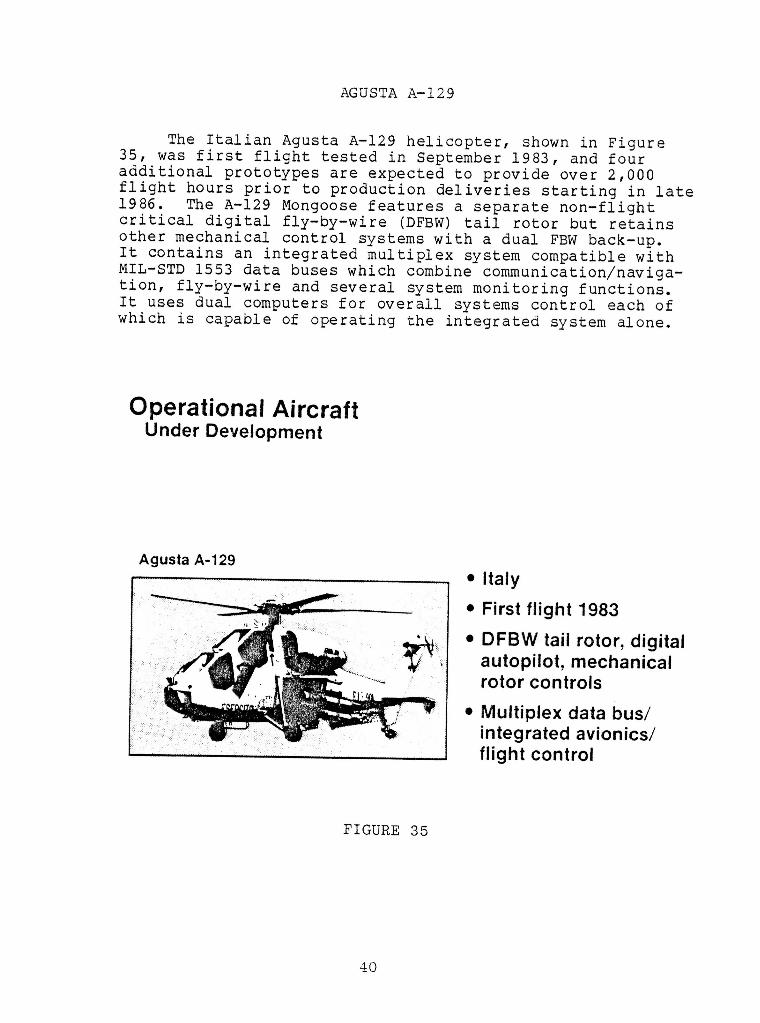
The Italian Agusta A-129 helicopter, shown in Figure •35, was first flight tested in September 1983, and four
I
additional prototypes are expected to provide over 2,000flight hours prior to production deliveries starting in late1986. The A-129 Mongoose features a separate non-flight icritical digital fly-by-wire (DFBW) tail rotor but retains
other mechanical control systems with a dual FBW back-up, iIt contains an integrated multiplex system compatible with mMIL-STD 1553 data buses which combine communication/naviga-tion, fly-by-wire and several system monitoring functions. iIt
uses dual computers for overall systems control each of iwhich is capable of operating the integrated system alone.
IOperationalAircraft i
Under Development
I!
Agusta A-129 I• Italy
• First flight 1983 i
_ • DFBW tail rotor, digital__. autopilot, mechanicalrotor controls i
• Multiplex data bus/integrated avionics/ !flight control
IFIGURE 35 I
!!
40
!
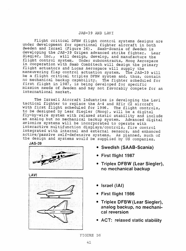
JAS-39 AND LAVI
Flight critical DFBW flight control systems designs areunder development for opertional fighter aircraft in bothSweden and Israel (Figure 36). Saab-Scania of Sweden isdeveloping the JAS-39 Gripen advanced strike fighter. LearSiegler, Inc., will design, develop, and manufacture theflight control system. Under subcontracts, Moog Aerospacein cooperation with Saab Combitech will design the primaryflight actuators and Lucas Aerospace will supply themaneuvering flap control actuation system. The JAS-39 willbe a flight critical triplex DFBW system and, thus, containno mechanical backup capability. The fighter scheduled forfirst flight in 1987, is being developed for specificmission needs of Sweden and may not favorably compete for aninternational market.
The Israeli Aircraft Industries is developing the Lavitactical fighter to replace the A-4 and Kfir C2 aircraftwith first flight scheduled for 1986. The flight controls,to be designed by Lear Siegler (Moog), will be a digitalfly-by-wire system with relaxed static stability and includean analog but no mechanical backup system. Advanced digitalavionics systems will be incorporated to operate withinteractive multifunction displays/controls, fire controlintegrated with internal and externa! sensors, and enhancedactive/passive self-defensive systems. As planned, much ofthe design and systems would be supplied by US companies.
JAS-39• Swedish (SAAB-Scania)
• First flight 1987
i • Triplex DFBW (Lear Siegler),no mechanical backup
i LAVI• Israel (IAI)
I u, _'_' _ • "• First flight 1986
i • Triplex DFBW(Lear Siegler),analog backup, no mechani-cal reversion
_ • ACT: relaxed static stability
R ,,, , . .....
FIGURE 36
II
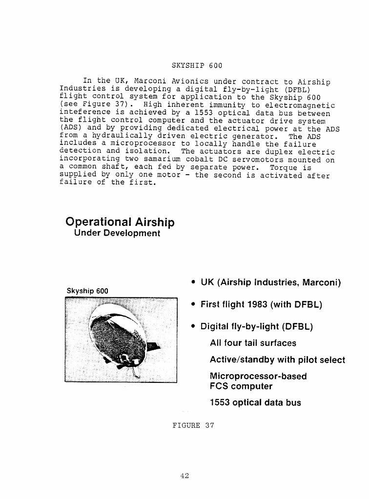
SKYSHIP 600 IIn the UK, Marconi Avionics under contract to Airship
Industriesis developinga digital fly-by-light(DFBL) •flight control system for applicationto the Skyship 600 |(see Figure 37). High inherent immunityto electromagneticinteferenceis achieved by a 1553 optical data bus betweenthe flight control computer and the actuator drive system I(ADS)and by providingdedicated electricalpower at the ADSfrom a hydraulicallydriven electricgenerator. The ADSincludes a microprocessorto locally handle the failure •detection and isolation. The actuatorsare duplex electricincorporatingtwo samariumcobalt DC servomotorsmounted ona common shaft, each fed by separatepower. Torque is •suppliedby only one motor - the second is activated after mfailure of the first.
!Operational Airship |
Under Development
I|
• UK (Airship Industries, Marconi) •Skyship 600
III
• First flight 1983 (with DFBL) II
• Digital fly-by-light (DFBL) IAll four tail surfaces
Active/standby with pilot select !
Microprocessor-based IFCS computer
1553 optical data bus I
FIGURE 37 n
I
!
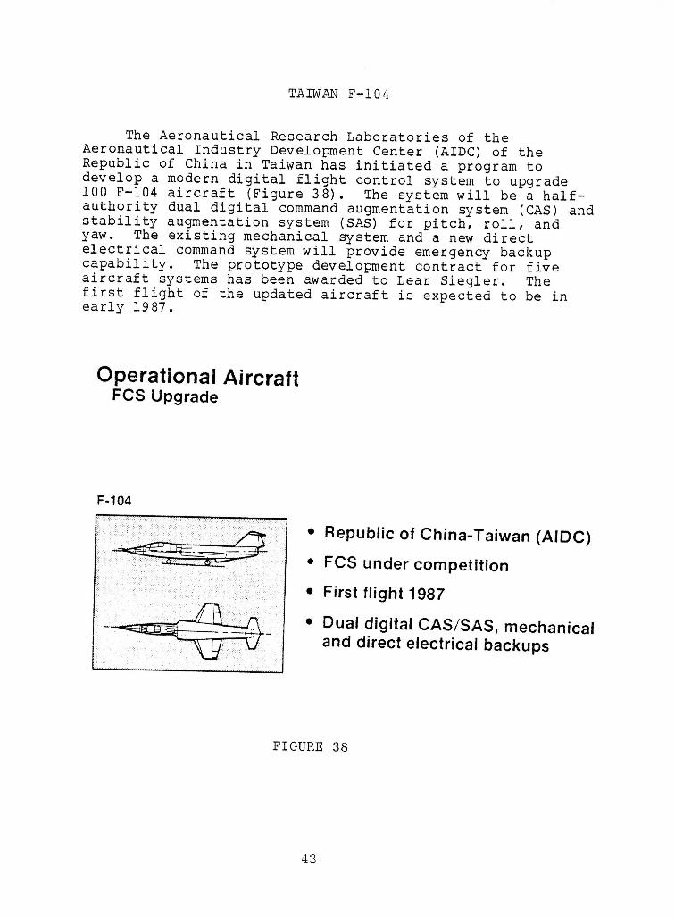
i TAIWAN F-104
i The Aeronautical Research Laboratories of theAeronautical Industry Development Center (AIDC) of the
i Republic of China in Taiwan has initiated a program todevelop a modern digital flight control system to upgradei00 F-104 aircraft (Figure 38). The system will be a half-
i authority dual digital command augmentation system (CAS) andstability augmentation system (SAS) for pitch, roll, andyaw. The existing mechanical system and a new directelectrical command system will provide emergency backup
i capability. The prototype development contract for fiveaircraft systems has been awarded to Lear Siegler. Thefirst flight of the updated aircraft is expected to be in
I early 1987.
m Operational AircraftFCS UpgradeI
!i F-104
• Republic of China-Taiwan (AIDC)
i • FCS under competition
I • First flight 1987• Dual digital CAS/SAS, mechanical
and direct electrical backups
!i FIGURE 38
!!
43
!
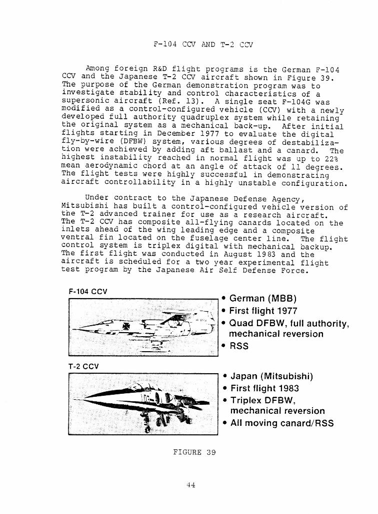
!F-104 CCV AND T-2 CCV I
m
Among foreign R&D flight programs is the German F-104 •CCV and the Japanese T-2 CCV aircraft shown in Figure 39. i
The purpose of the German demonstration program was toinvestigate stability and control characteristics of asupersonic aircraft (Ref. 13). A single seat F-104G wasmodified as a control-configured vehicle (CCV) with a newlydeveloped full authority quadruplex system while retaining •the original system as a mechanical back-up. After initial Iflights starting in December 1977 to evaluate the digitalfly-by-wire (DFBW) system, various degrees of destabiliza- ition were achieved by adding aft ballast and a canard. The •highest instability reached in normal flight was up to 22%
i
mean aerodynamic chord at an angle of attack of II degrees.The flight tests were highly successful in demonstrating iaircraft controllability in a highly unstable configuration. i
Under contract to the Japanese Defense Agency, •Mitsubishi has built a control-configured vehicle version ofthe T-2 advanced trainer for use as a research aircraft.The T-2 CCV has composite all-flying canards located on the iinlets ahead of the wing leading edge and a composite Iventral fin located on the fuselage center line. The flightcontrol system is triplex digital with mechanical backup.The first flight was conducted in August 1983 and the naircraft is scheduled for a two year experimental flighttest program by the Japanese Air Self Defense Force.
F-104CCV i• German (MBB) ,,=,
-_ • First flight 1977 i
_" __ "_ • Quad DFBW, full authority,mechanical reversion i
" RSS
T-2 CCV I• Japan (Mitsubishi)
• First flight 1983 n• Triplex DFBW,
mechanical reversion I• All moving canard/RSS
!FIGURE 39
I
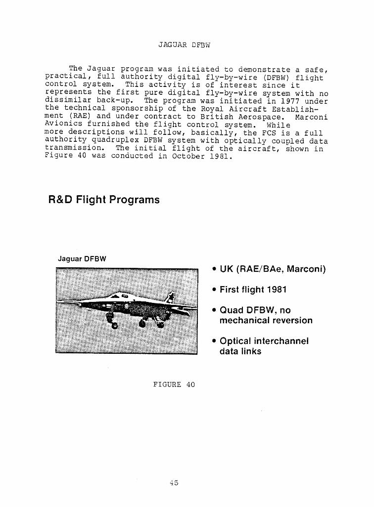
JAGUAR DFBW
The Jaguar program was initiated to demonstrate a safe,practical, full authority digital fly-by-wire (DFBW) flightcontrol system. This activity is of interest since itrepresents the first pure digital fly-by-wire system with nodissimilar back-up. The program was initiated in 1977 underthe technical sponsorship of the Royal Aircraft Establish-ment (RAE) and under contract to British Aerospace. MarconiAvionics furnished the flight control system. Whilemore descriptions will follow, basically, the FCS is a fullauthority quadruplex DFBW system with optically coupled datatransmission. The initial flight of the aircraft, shown inFigure 40 was conducted in October 1981.
R&D Flight Programs
Jaguar DFBW• UK (RAE/BAe, Marconi)
• First flight 1981
• Quad DFBW, nomechanical reversion
I • Optical interchannel
i data links
I FIGURE 40
III
!N
JAGUAR DFBW SYSTEM ARCHITECTURE
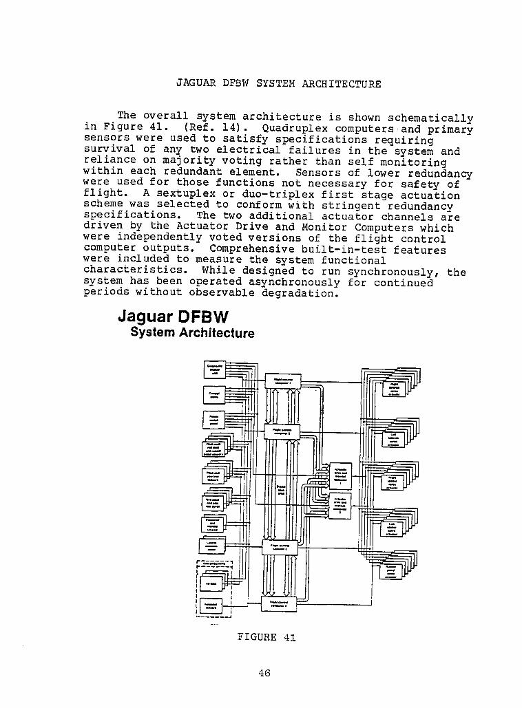
!The overall system architecture is shown schematically
in Figure 41. (Ref. 14). Quadruplex computers and primary •sensors were used to satisfy specifications requiringsurvival of any two electrical failures in the system andreliance on majority voting rather than self monitoring •within each redundant element. Sensors of lower redundancy Hwere used for those functions not necessary for safety offlight. A sextuplex or duo-triplex first stage actuationscheme was selected to conform with stringent redundancy ispecifications. The two additional actuator channels aredriven by the Actuator Drive and Monitor Computers whichwere independentlyvoted versions of the flight control icomputer outputs. Comprehensivebuilt-in-testfeatureswere included to measure the systemfunctionalcharacteristics. While designed to run synchronously,the •system has been operated asynchronouslyfor continued iperiods without observable degradation.
Jaguar DFBW iSystem Architecture
l
4o !
Ii JAGUAR DFBW - COMPUTINGAND MONITORINGARCHITECTURE
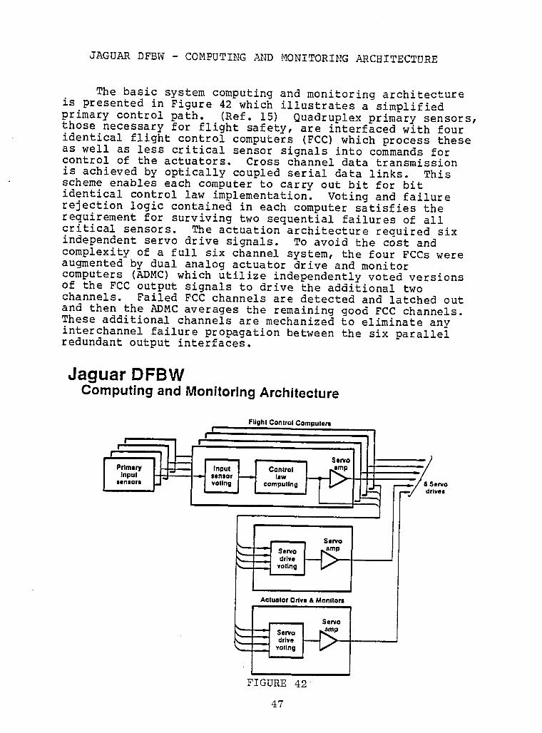
The basic system computingand monitoringarchitectureillustratesa simplifiedI is presented in Figure 42 which
primary control path. (Ref. 15) Quadruplexprimary sensors,those necessaryfor flight safety,are interfacedwith four
I identicalflight control computers (FCC)which process theseas well as less criticalsensor signals into commands for
I ontrol of the actuators. Cross channel data transmissionis achieved by opticallycoupled serial data links. Thisscheme enables each computer to carry out bit for bitidenticalcontrol law implementation. Voting and failurerejectionlogic containedin each computer satisfiesthe
I for two failuresof allrequirement surviving sequentialcritical sensors. The actuationarchitecturerequired sixindependentservo drive signals. To avoid the cost and
I complexityof a full six channel system, the four FCCs wereaugmented by dual analog actuator drive and monitorcomputers (ADMC)which utilize independentlyvoted versions
I of the FCC output signals to drive the additionaltwochannels. Failed FCC channels are detected and latched outand then the ADMC averages the remaininggood FCC channels.These additionalchannels are mechanizedto eliminateany
sixinterchannelfailure propagationbetween the parallelI redundantoutput interfaces.
I! Jaguar .DFBW .
I Compuhng and Monitoring ArchitectureFlight Control Computers
11 ' , '
i I
' " 'I cont,olI_._r_ll -_/I ,..,o,, IJ- I I ,o,,.gI I =om,.t,.g ..../ ,S...oI I I I I I " _-/ o.v,,
I !• I _ Servo
'I Actuator Drive & Monllorl
i _ Servo
I i II
FIGURE 42
I 47
I
JAGUAR DFBW-DUO-TRIPLEX ACTUATOR SCHEME I
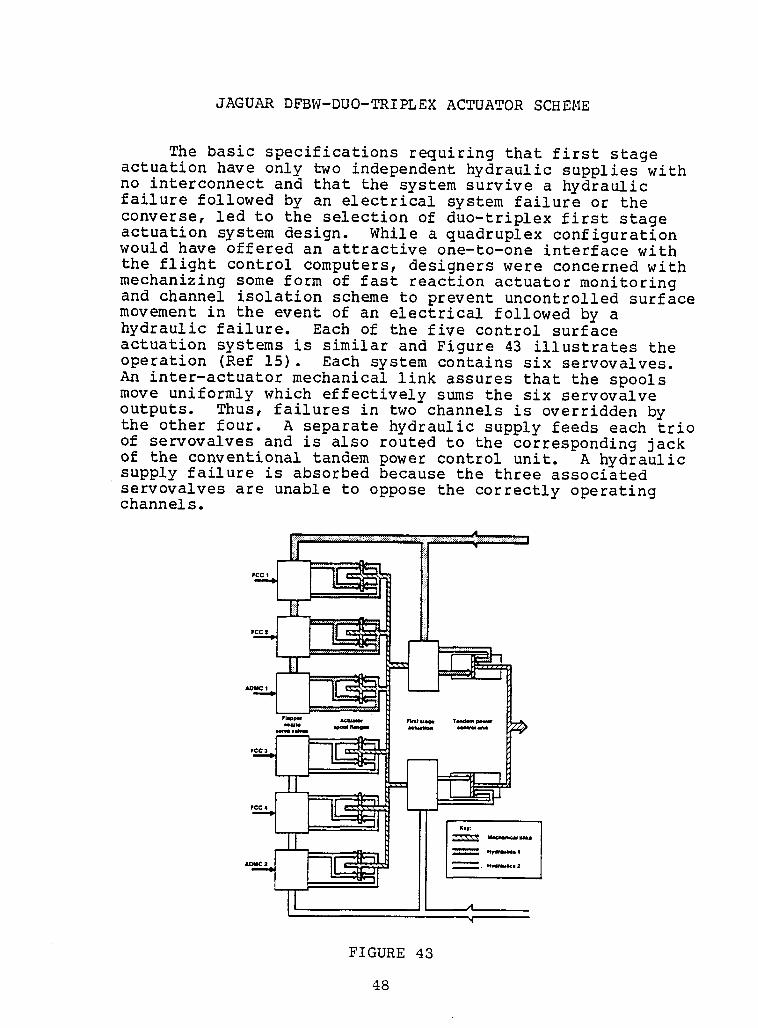
The basic specificationsrequiringthat first stage •actuationhave only two independenthydraulicsupplieswithno interconnectand that the system survive a hydraulic •failure followed by an electricalsystem failure or the |converse,led to the selectionof duo-triplexfirst stageactuation system design. While a quadruplexconfigurationwould have offered an attractiveone-to-oneinterfacewith Ithe flight control computers,designerswere concernedwithmechanizingsome form of fast reactionactuator monitoringand channel isolationscheme to prevent uncontrolledsurface •movement in the event of an electricalfollowed by ahydraulicfailure. Each of the five control surfaceactuationsystems is similar and Figure 43 illustratesthe •operation (Ref 15). Each system containssix servovalves. nAn inter-actuatormechanicallink assures that the spoolsmove uniformlywhich effectivelysums the six servovalve n
outputs. Thus, failures in two channels is overriddenby Ithe other four. A separate hydraulicsupply feeds each trioof servovalvesand is also routed to the correspondingjackof the conventionaltandem power control unit. A hydraulicsupply failure is absorbed because the three associatedservovalvesare unable to oppose the correctlyoperatingchannels. •
|
III
"- |
I
IJAGUAR DFBW - SOFTWARE DEVELOPMENT PROCESS
!The use of common software in the flight control system
presented the potential of a generic error leading to a
I safety critical loss of control. Therefore it was necessaryto provide maximum software visibility to facilitate thoroughtesting and functional auditing during the design phase,
I supplemented by clear requirements definition, detaileddocumentation and stringent production and configurationcontro! procedures. (Ref. 16) The key documents controlling
i the software design are the System Requirements Document(SRD) which controls the design implementation and theSoftware Structure Development (SSD). The SSD defines therunning order of the modules within each program segment and
I is designed to assure strict sequential data flow.
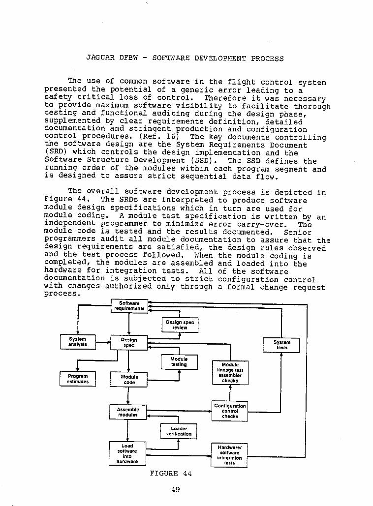
The overall software development process is depicted in
I Figure 44. The SRDs are interpreted to produce softwaremodule design specifications which in turn are used formodule coding. A module test specification is written by an
I independent programmer to minimize error carry-over. Themodule code is tested and the results documented. Senior
programmers audit all module documentation to assure that thedesign requirements are satisfied, the design rules observed
I and the test followed. When the module isprocess codingcompleted, the modules are assembled and loaded into thehardware for integration tests. All of the software
I documentation is subjected to strict configuration controlwith changes authorized only through a forma! change requestprocess.
' Ii'"requirements 12 ' '
I- , i
Design spec
review
{ Sys,em_._ DesignL, _ I System}analysis spec | tests
[ '-I ' I{
Moduletesting Modulelineage test
Program I Module _ T assembleri --e. T TI Assemble Ii _ control
modules i _ I / checks
I I [ ve'L'if°l_ tei_)n ]Load _ | Hardware/
software ! softwareI into ' integration
hardware tests
FIGURE 44
II
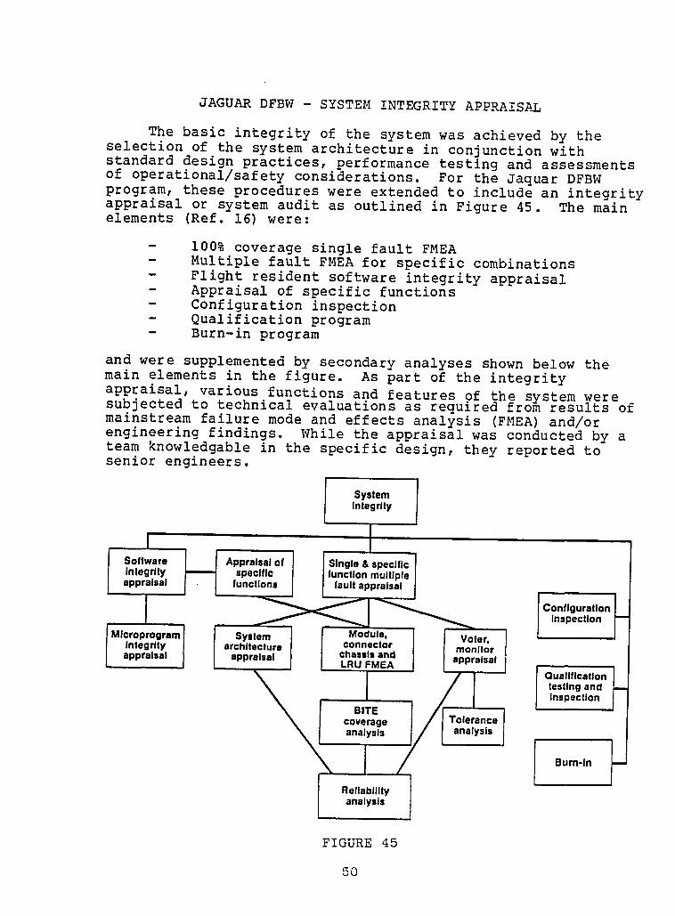
JAGUAR DFBW - SYSTEM INTEGRITY APPRAISAL
The basic integrity of the system was achieved by the I
i
selection of the system architecture in conjunction withstandard design practices, performance testing and assessmentsof operational/safetyconsiderations. For the Jaquar DFBW iprogram, these procedureswere extended to include an integrity
iappraisal or system audit as outlined in Figure 45. The mainelements (Ref. 16) were: I
i
- 100% coverage single fault FMEA- Multiple fault FMEA for specific combinations- Flight resident software integrityappraisal i- Appraisal of specific functions- Configurationinspection i- Qualification program i- Burn-in program
and were supplemented by secondary analyses shown below themain elements in the figure. As part of the integrity
appraisal, various functions and features of the system weresubjectedto technicalevaluationsas requiredfrom results of []mainstreamfailure mode and effects analysis (FMEA)and/orengineeringfindings. While the appraisalwas conducted by ateam knowledgable in the specific design, they reported to •senior engineers. n
System [IntegrJly i
is._ o,, nInlegrlty specific _ functionmultipleI
.,,ro,.o,,no,,_oo,j "°"_'"°'"'n ni
,, Inspeclion
I Mlcr°pr°gram' System I l M°dule' I l V°ter' i
Integrity _ architecture connector monitor
l appraisal I appraisal chassis and appraisalLRU FMEA
I Qualification __ I
testing andinspection
BITEcoverage Tolerance
analysis analysis i
Bum-in _-Reliability Ianalysis
FIGURE 45 I
_o I
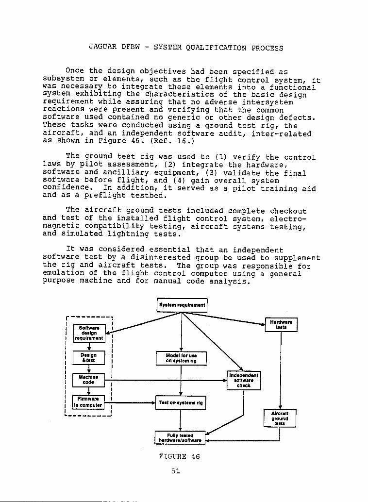
II JAGUAR DFBW - SYSTEM QUALIFICATION PROCESS
I Once the design objectives had been specified assubsystem or elements, such as the flight control system, itwas necessary to integrate these elements into a functional
I system exhibiting the characteristics of the basic designrequirement while assuring that no adverse intersystemreactions were present and verifying that the common
I software used contained no generic or other design defects.These tasks were conducted using a ground test rig, theaircraft, and an independent software audit, inter-related
i as shown in Figure 46. (Ref. 16.)The ground test rig was used to (i) verify the control
laws by pilot assessment, (2) integrate the hardware,
I software and ancilliary (3) validateequipment, the final
software before flight, and (4) gain overall systemconfidence. In addition, it served as a pilot training aid
I and as a preflight testbed.
The aircraft ground tests included complete checkout
i and test of the installed flight control system, electro-magnetic compatibility testing, aircraft systems testing,and simulated lightning tests.
I It was considered essential that anindependent
software test by a disinterested group be used to supplementthe rig and aircraft tests. The group was responsible for
I emulation of the flight control computer using a generalpurpose machine and for manual code analysis.
I Systemrequirement
I ' H.rdwre ;Software bl_bl
designrequirement
I Design Modelfor use& test on systemrig
I Machine t Indepand_mt
softwarecode I check
t
' f rI Firmware I I i
I_ Test on stems rigIn computer I
L..... / AlrcreNground
I leits
I FIGURE. 46
51
!
!!
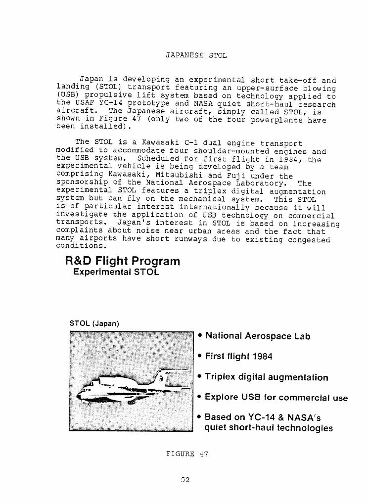
JAPANESE STOL
IJapan is deve!oping an experimental short take-off and
landing (STOL)transportfeaturingan upper-surfaceblowing [](USB)propulsivelift system based on technologyapplied to |the USAF YC-14 prototype and NASA quiet short-haulresearchaircraft. The Japanese aircraft,simply called STOL, isshown in Figure 47 (onlytwo of the four powerplantshave Ibeen installed). []
The STOL is a KawasakiC-I dual engine transport []modified to accommodatefour shoulder-mountedengines and |the USB system. Scheduledfor first flight in 1984, theexperimentalvehicle is being developedby a team •comprisingKawasaki,Mitsubishiand Fuji under the |sponsorshipof the National AerospaceLaboratory. TheexperimentalSTOL features a triplexdigital augmentationsystem but can fly on the mechanical system. This STOL •is of particular interestinternationallybecause it will
mm
investigatethe applicationof USB technologyon commercialtransports. Japan's interest in STOL is based on increasingcomplaintsabout noise near urban areas and the fact that lmany airports have short runways due to existing congested
conditions. IR&D Flight Program
Experimental STOL I
!STOL(Japan)
• National Aerospace Lab |
• First flight 1984 I
• Triplex digital augmentation
• Explore USB for commercial use
• Based on YC-14 & NASA's
quiet short-haul technologies I
FIGURE 47 I
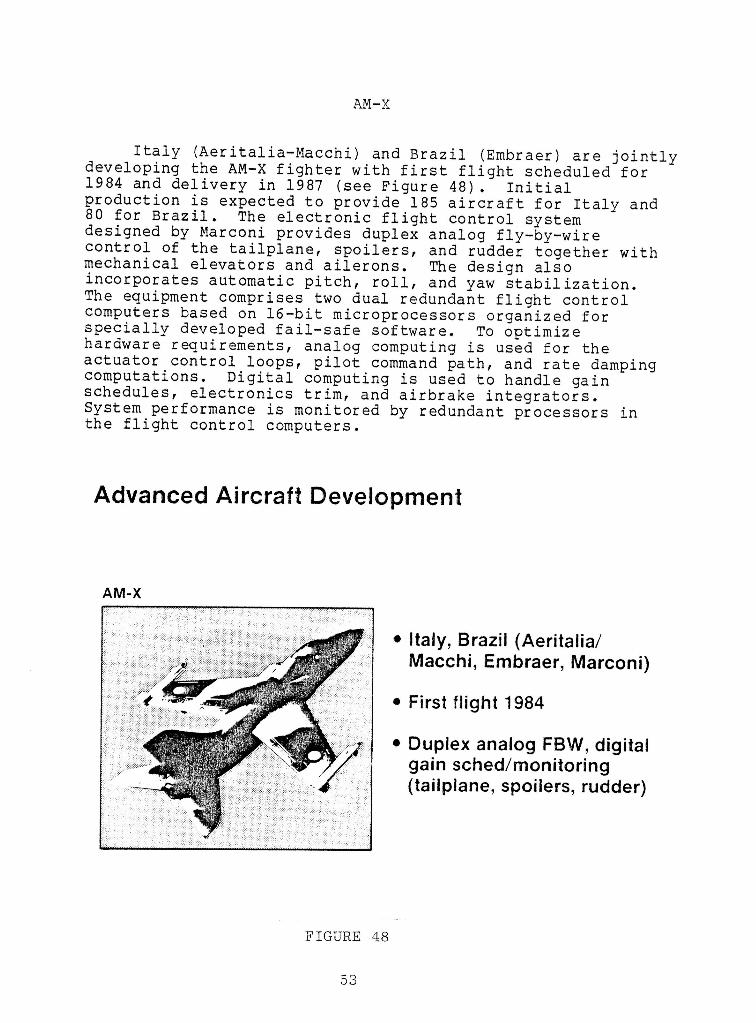
!I AM-X
i Italy (Aeritalia-Macchi) and Brazil (Embraer) are jointlydeveloping the AM-X fighter with first flight scheduled for
i 1984 and delivery in 1987 (see Figure 48). Initialproduction is expected to provide 185 aircraft for Italy and80 for Brazil. The electronic flight control systemdesigned by Marconi provides duplex analog fly-by-wire
i control of the tailplane, spoilers, and rudder together withmechanical elevators and ailerons. The design alsoincorporates automatic pitch, roll, and yaw stabilization.
i The equipment comprises two dual redundant flight controlcomputers based on 16-bit microprocessors organized forspecially developed fail-safe software. To optimize
i hardware requirements, analog computing is used for theactuator control loops, pilot command path, and rate dampingcomputations. Digital computing is used to handle gain
i schedules, electronics trim, and airbrake integrators.System performance is monitored by redundant processors inthe flight control computers.
IAdvanced Aircraft DevelopmentI
!AM-X
i • Italy, Brazil (Aeritalia/
i Macchi, Embraer, Marconi)• First flight 1984
I • Duplex analog FBW, digitalgain sched/monitoring
i (taiiplane, spoilers, rudder)
!!I FIGURE 48
m 53
!ADVANCED EUROPEAN FIGHTER DEVELOPMENT I
Plans are underway for the development of a common HEuropean fighter aircraft for the 1990s, called the FutureEuropean Fighter Aircraft (FEFA). It is an outgrowth ofthree separate preliminary design efforts undertaken by the nOK, France and Germany. While some joint collaborationexists on these design efforts, economic considerations makeit unlikely that more than one would be fully developed. •Thus, at the time of this writing, these three countries |joined by Italy and Spain have outlined basic operationalrequirements for the FEFA which will be a STOL vehicle and n
rely heavily on advanced composites. Advanced digitalflight controls will play an important role since current
m
combat aircraft developments and research activities inEurope concentrate on this technology. While specificmission requirements would be compromised, such a jointEuropean effort would create an attractive production marketand serve as a formidable obstacle for US competitors. •Prototypes of the FEFA vehicle are expected in the 1990-1991 |time period to provide an operational date of 1995. Initialplans call for 400 planes for France and Germany, 150 forthe UK and 125 each for Italy and Spain. Some other |European activities which have led to the FEFA and which maybe modified because of the recent agreements are discussed
below, i
Led by British Aerospace, a seven member industrial
consortium has an agreement with the British Ministry of •Defense for government funding up to and including first mflight for the development of an Agile Combat Aircraft (ACA)technology demonstrator called an Experimental Aircraft •Program (EAP). (See Figure 49) Both West German and HItalian aerospace companies have contributed some fundingand while not committed, the West German and possibly theItalian governments may fund a second demonstrator aircraft, nThe ACA flight control system design by Marconi Avionics i
would be quadruplex digital fly-by-wire (DFBW) with nomechanical backup and no dissimilar redundancy. (Marconiconsiders that while not required for military application,dissimilar redundancy is necessary in commercial aircraft
for certification purposes.) n
France has a comparable program since Dassault-Berguethas begun manufacture of one technology demonstrator n
aircraft - Avion de Combat Experimental (ACX) as shown in •the figure. It will be a DFBW design with no mechanical
u
backup and include electrical and fiber optics data busing,voice control system, holographic displays, and provision nfor anti-turbulence ride contro! in the automatic computer- |controlled flight control system.
Is4 |
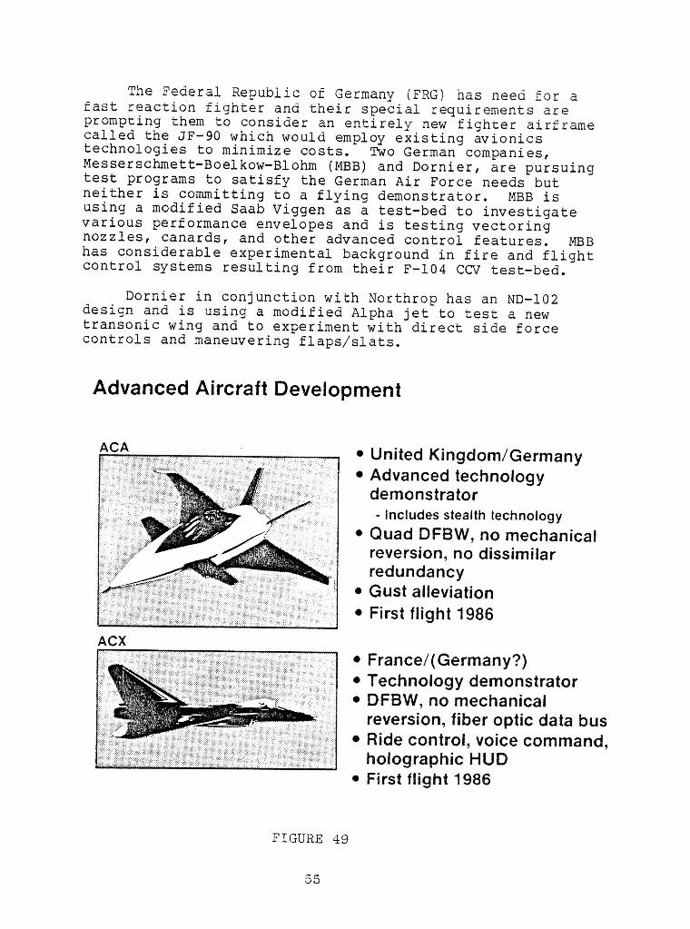
The Federal Republic of Germany (FRG) has need for afast reaction fighter and their special requirements areprompting them to consider an entirely new fighter airframecalled the JF-90 which would employ existing avionicstechnologies to minimize costs. Two German companies,Messerschmett-Boelkow-Blohm (MBB) and Dornier, are pursuingtest programs to satisfy the German Air Force needs butneither is committing to a flying demonstrator. MBB isusing a modified Saab Viggen as a test-bed to investigatevarious performance envelopes and is testing vectoringnozzles, canards, and other advanced control features. MBBhas considerable experimental background in fire and flightcontrol systems resulting from their F-104 CCV test-bed.
Dornier in conjunction with Northrop has an ND-102design and is using a modified Alpha jet to test a newtransonic wing and to experiment with direct side forcecontrols and maneuvering flaps/slats.
Advanced Aircraft Development
ACA • United Kingdom/Germany• Advanced technology
demonstrator
i - Includes stealth technology• Quad DFBW, no mechanical
reversion, no dissimilarI redundancy
• Gust alleviation
• First 1986flight
ACX
• France/(Germany?)• Technology demonstrator
I • DFBW, no mechanicalreversion, fiber optic data bus• Ride control, voice command,
holographic HUD• First flight 1986
IFIGURE 49
55
I
Ii
OTHER FOREIGN SYSTEMS
!Two other major foreign programs were identified in
the survey that are either under development or planned, but
very little information has been assembled at this time. i
Agusta of Italy and Westland of the UK have teamed to
form EH Industries Ltd., (EHI) to develop a new helicopter, •the EH-101, to replace the Sikorsky SH-3D Sea King that isused by both navies. They also hope to market utility andcivil versions. Smiths Industries of the OK is developing •what they refer to as a DFBW but it is not clear whether ithere is a mechanical primary or reversion system. The firstof nine pre-production aircraft is to be ready for flight in
1986. i
The OK Royal Aircraft Establishment (RAE) has initiateda major new thrust: VSTOL advanced aircraft control •technology (VAAC) program. It appears to be focused onintegrated fire, flight, and thrust vector control for
single pilot operation including weapon delivery. Smiths •Industries is working on a flight control system for the iRAE. Flight tests may be conducted on a Harrier aircraftbut it is not known whether the flight test would include anadvanced DFBW or not.d i
II!iIIIi
IIII!IIIiI TECHNOLOGY TRENDS
IIIiIiI|
57
I

IIIIIIIIIIIIIIIIIII
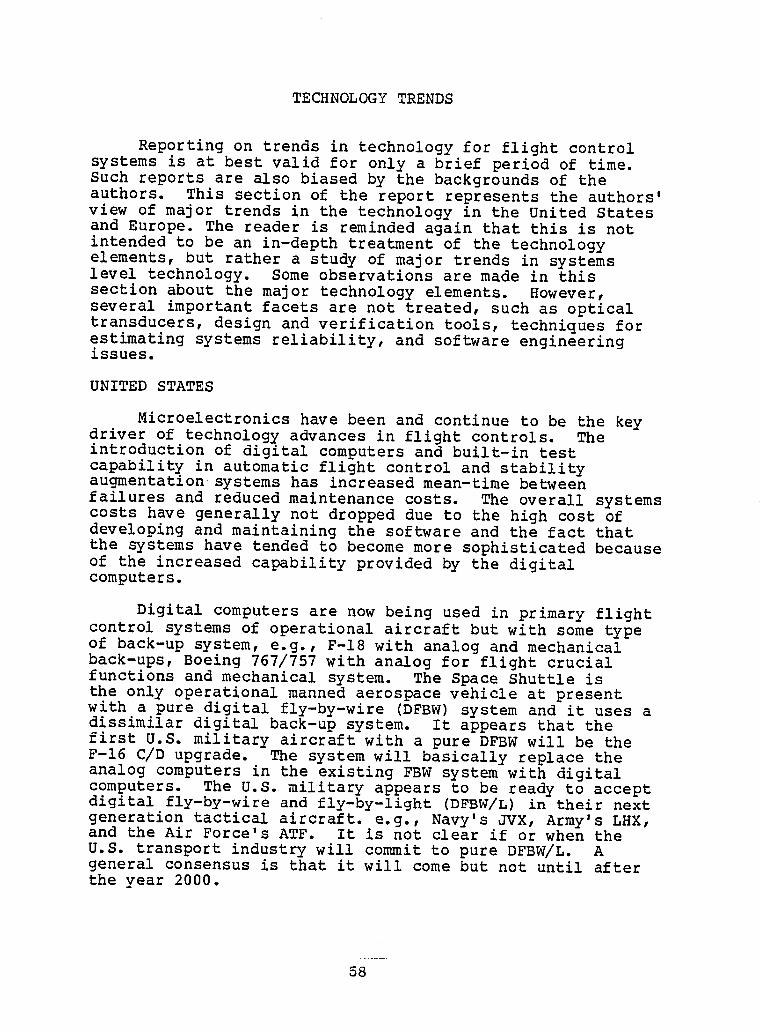
!l TECHNOLOGY TRENDS
I Reporting on trends in technology for flight controlsystems is at best valid for only a brief period of time.Such reports are also biased by the backgrounds of the
I authors. This section of the report represents the authors'view of major trends in the technology in the United Statesand Europe. The reader is reminded again that this is not
l intendedto be an in-depth treatmentof the technologyelements,but rathera study of major trends in systemslevel technology. Some observationsare made in this
l section about the major technologyelements. However,several importantfacets are not treated, such as opticaltransducers,design and verificationtools,techniquesforestimatingsystems reliability,and softwareengineering
l issues.UNITED STATES
I Microelectronicshave been and continue to be the keydriver of technologyadvances in flight controls. The
l introductionof digital computersand built-in testcapabilityin automaticflight controland stabilityaugmentationsystems has increasedmean-time betweenfailures and reducedmaintenancecosts. The overall systems
l costs have generallynot dropped due to the high COSt ofdevelopingand maintainingthe softwareand the fact thatthe systemshave tended to become more sophisticatedbecause
l of the increasedcapabilityprovided by the digitalcomputers.
l Digital computersare now being used in primary flightcontrol systems of operationalaircraft but with some typeof back-up system, e.g., F-18 with analog and mechanical
l back-ups,Boeing 767/757with analog for flight crucialfunctionsand mechanicalsystem. The Space Shuttle isthe only operationalmanned aerospacevehicle at presentwith a pure digital fly-by-wire(DFBW)system and it uses a
I dissimilardigital back-up system. It that theappears
first U.S. military aircraftwith a pure DFBW will be theF-16 C/D upgrade. The systemwill basicallyreplace the
I analog computersin the existingFBW systemwith digitalcomputers. The U.S. military appears to be ready to acceptdigital fly-by-wireand fly-by-light (DFBW/L)in their next
i generationtacticalaircraft,e.g., Navy's JVX, Army's LHX,and the Air Force's ATF. It is not clear if or when theU.S. transportindustrywill committo pure DFBW/L. Ageneral consensusis that it will come but not until after
I the year 2000.
!
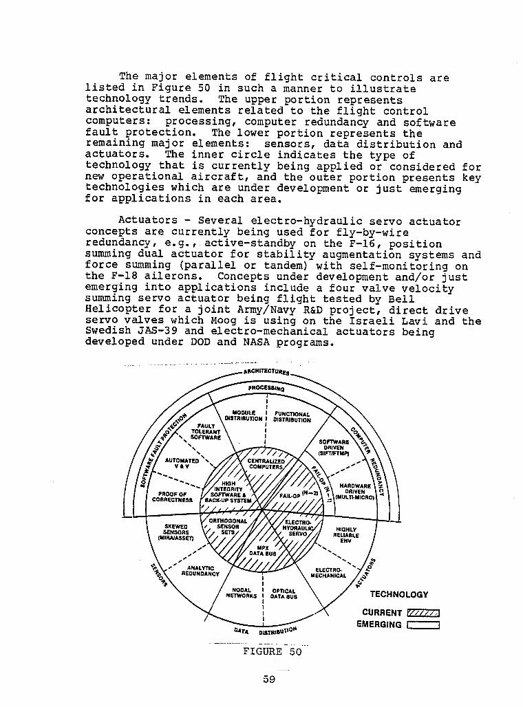
II
The major elements of flight critical controls arelisted in Figure 50 in such a manner to illustrate am
technologytrends. The upper portion represents Iarchitecturalelements related to the flight controlcomputers: processing,computer redundancyand softwarefault protection. The lower portion representsthe Iremainingmajor elements: sensors, data distributionandactuators. The inner circle indicatesthe type oftechnologythat is currentlybeing applied or consideredfor •new operationalaircraft,and the outer portion presents keytechnologieswhich are under developmentor just emergingfor applicationsin each area. I
|Actuators - Several electro-hydraulicservo actuator
concepts are currentlybeing used for fly-by-wire mm
redundancy,e.g., active-standbyon the F-16, position •summing dual actuator for stabilityaugmentationsystems and
m
force summing (paralle!or tandem)with self-monitoringonthe F-18 ailerons. Conceptsunder developmentand/or just •emerging into applicationsinclude a four valve velocitysumming servo actuator being flight tested by BellHelicopterfor a joint Army/NavyR&D project, direct drive •servo valves which Moog is using on the Israeli Lavi and the |Swedish JAS-39 and electro-mechanicalactuators beingdeveloped under DOD and NASA programs. I
pROC_SS//VQ I
MODULE FUNCTIONAL
FAULT DISTRIBUTION DISTRIBUTION iTOLERAN'
_% SOFTWARE 50FTWARE"_,, DRIVEN
_, (SlFTIFTMP) I
AUTOMATED_'_, CENTRALIZEDV&V ""
HARDWARE
INTEGRITY DRIVEN IPROOFOF SOFTWARE •
CORRECTNESS BACK-UPSYSTEM
SKEWED HIGHLY ISENSORS RELIABLE(MIRJUASSET) EHV
I" DATA BUS "_"',,,,.
• • •REDUNDANCY"ANALYTIC MECHANIcALELECTRO-"/._'_, INETWORXS.ORAL DATABUSOPncAL TECHNOLOGY m
.-/_ CURRENT IEMERGING
DATA DISTRtBUI[tOft I
II Data Distribution - Multiplex (MPX) data buses are used
extensively in avionics systems in the most recentoperational aircraft, e.g., F/A-18 uses MIL-STD-1553
I (Reference2) and B767/757 uses ARINC 429 (Reference17).Currently,the buses are twistedwire pairs. They are usedin coupling sensor data to flight control systems primarily
I or outer loop functions. Flight criticalfunctionsarestill dedicatedwires and not multiplex data buses, e.g.,the yaw damper on the B-767/757. All of the command
i augmentationsystem functionson the F/A-18 are dedicatedwires. Mission avionicsare on the data bus and interfacewith the flight control computers.
I An importantemergingtechnologyis the dataopticalbus. A primary motivationfor that on flight criticalcontrols is the protectionfiber optics provide from EMI and
I MP. Severa! laboratoryand flight test programs have beenconductedon optical data bus technology,the mostsignificantof which is the Army's ADOCS Program outlined
I arlier in the report. This type of technologyis expectedto be incorporatedinto the Navy JVX and the Army LHXvehicles. MIL-STD-1773has been proposed as the military
i standardfor fiber optic multiplex data buses.Various new approachesto providingincrease fault
toleranceon data buses are being studied (e.g.,References
I 18-21). A good review of alternatearchitecturesispresented in Reference22. One particularlyinterestingconcept is the "nodalnetwork,"describedin Reference22,
I which would provide many potentialpaths between criticalfunctionsand hence increase fault tolerance.
i Sensors - Individualsensor instrumentsfor flightcontrol functionsseem well developed,although new ideascontinueto emerge, such as the ring laser gyro and thefiber optics rotationsensor. The current practice is to
I se a fully redundantset of orthogonalsensors for fly-by-wire systems. Two new concepts are under developmentthathave the potentialof meeting the total system reliability
I equirementswith fewer sensors. One is analyticalredundancy (Reference23), which synthesizesmissingaircraftmotion parametersfrom alternateflight
I easurementsand the vehicle dynamics relationships. Theother is to skew certain sensors to measure componentsofmotion in more than one axis, then synthesizethe desiredorthogonalset of motion parameters (e.g.,MIRA in
I eferences24-26 and ASSET in References27 and 28. Failureof one instrumentcan not jeopardizethe augmentationin anyone axis.
!I
6O
I
!Processing- The aspect of processingin flight control i
addressedhere is the issue of centralizedversusdistributedprocessing. The current practice is to use •redundantcontrol computersfor all the primary flight Rcontrol system functionsand often the augmentationfunctions as well (e.g.,F/A-18 Reference 2). Functionaldistributionof the processingis beginning to appear on Hoperationalaircraft, e.g., separationof critical and non-critical functionsas in the yaw damper of the B-767/757(Reference17). Another form of distributedprocessing iwould be module distribution,where certain computationaltasks are off-loadedfrom the central computer,e.g., pre-processingand redundancymanagementof a sensor system or ismart actuators that defect failures and reconfigure. |
SoftwareFault Protection- It is virtually impossible ito assure that the software used in a DFBW system is 100% •fault free because of the enormous number of states that can l
exist. "Softwarefaults" can arise from such items as badspecification,erroneouscode and poor programming idiscipline. To protect against software faults causingpotential catastrophicsystem failures,the current practicein operationalsystems is to develop high integrity software •through good design techniquesand extensiveverificationand validation (V&V)and to provide a dissimilarbackupsystem (e.g.,F/A-18 Reference2). Several approachesare ibeing researchedto improve softwarefault protectionfrom Bnew mathematicaltechniques,such as proofs of correctness,to automatingthe V&V tests and fault tolerant software
concepts. !Computer Redundancy- The current approach to
redundancyis to use N multiple identicalchannels and •compare the outputs to detect failed channels. If a two"fail-op"capabilityis needed, then N must be 4
in such an approach. The AFTI-16 is flight testing an •approach to achieve (Fail-op)2 with three channels by a form lof self test to operate down to a single channel (Referenceii). Such approacheshave the potentialof achievingtotalsystem flight safety reliabilityof up to 10-7 failures for Bflight hour which generallymeets the military requirements.The commercialtransportcommunity is strivingfor a failureprobabilityof less than 10-9 for a i0 hour flight. Several •new architecturalconceptsfor improvedfault tolerance areunder development. Three new conceptsare discussed in the
next section, i
!i
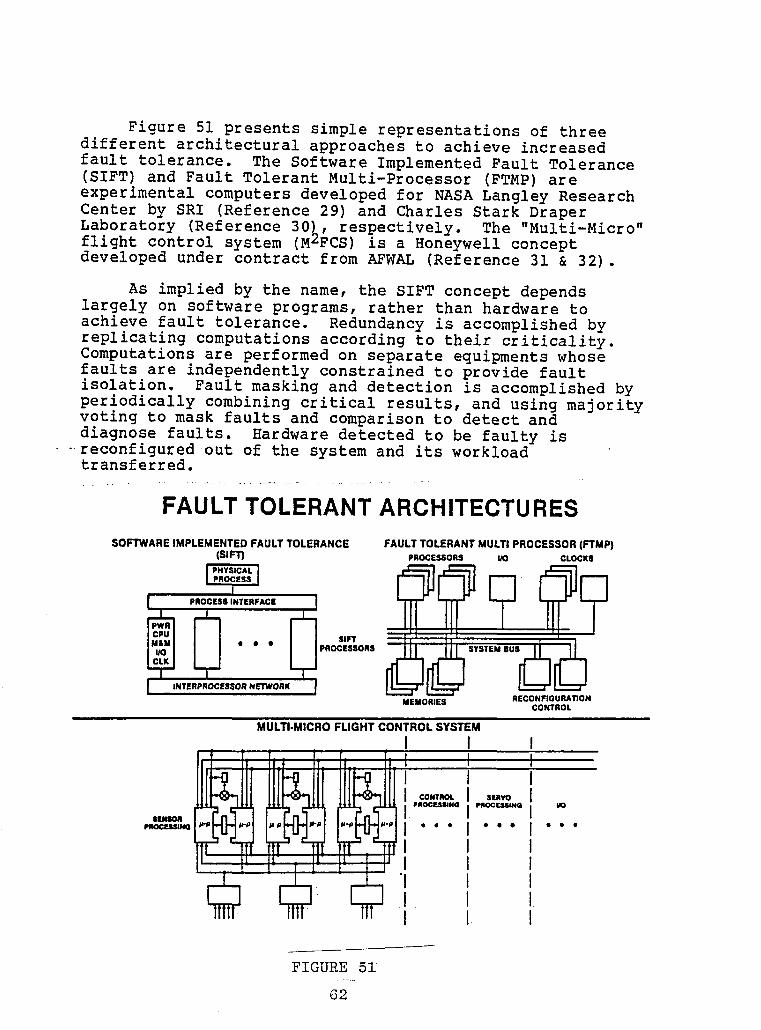
IIi Figure 51 presents simple representationsof threedifferent architecturalapproachesto achieve increased
fault tolerance. The Software ImplementedFault Tolerance(SIFT)and Fault TolerantMulti-Processor(FTMP)are
i experimentalcomputersdevelopedfor NASA ResearchLangleyCenter by SRI (Reference29) and Charles Stark DraperLaboratory (Reference30h, respectively. The "Multi-Micro"
i flight control system (MzFCS)is a Honeywellconceptdeveloped under contract from AFWAL (Reference31 & 32).
i As implied by the name, the SIFT concept dependslargely on softwareprograms,rather than hardware toachieve fault tolerance. Redundancyis accomplishedbyreplicatingcomputationsaccordingto their criticality.
i performedon separate equipmentswhoseComputationsarefaults are independentlyconstrainedto provide faultisolation. Fault masking and detection is accomplishedby
i periodicallycombiningcritical results,and using majorityvoting to mask faults and comparisonto detectanddiagnose faults. Hardwaredetected to be faulty is
i reconfiguredout of the system and its workloadtransferred.
II FAULT TOLERANT ARCHITECTURESSOFTWAREIMPLEMENTEDFAULTTOLERANCE FAULTTOLERANT MULTI PROCESSOR(F'rMP)
i (SIFT) eROCESSORS UO CLOCXSIPHYSICAL ]I pnocessI
Il eROC.,INTER,ACE]
• • • I I PROCESSORS
I I ,N'rFRPROC,S$OR NETWORK IMEMORIES RECONFIOURATION
CONTROL
I MULTI.MICROFLIGHTCONTROLSYSTEMI I
i ,,.R I_EIII_PI_ • • • • • • • • •
I
, I. /
i I l IFIGURE 51
I
iThe FTMP concept is a multiprocessorcomputer that uses i
hardware replicationfor redundancy. For this system, highreliabilityis achieved by forming processorsand memories iinto
computer and memory triads connectedby a triad of ibuses. Typically,a number of triads perform as a multi-processor. Each member of a single triad executesidenticalprograms in synchronizationwith the other members, iThe triad can mask failures and detect the faulty module.If spares are available,faulty units are replaced. If nospare is available,the triad in the operatingset is lost, •but two spares are created from the two "good"modules. The mmulti-processoris designed so that sufficientcapacityexists to conduct critical tasks with the remainingtriads. •
The M2FCS is an ultra-reliablereal-timecontrol systembased on two conceptualbuilding blocks - the self checkingpair (SCP)and the informationtransfer system (ITS). The iSCP is comprisedof two identicalhalves for redundancyand
i
each half contains two processors- one for control and dataprocessing;and the other, a bus interfaceunit, for icommunicationswith the rest of the system. The halvesperform identicalfunctionsand are disconnectedfrom thesystem if the outputs are not identical. The ITS is the •heart of the fault tolerant system and allows the consistent nexchange of data. It is tolerant of its own internal faultsand protectedagainst external hazards.
H!!I!iii
I63 i
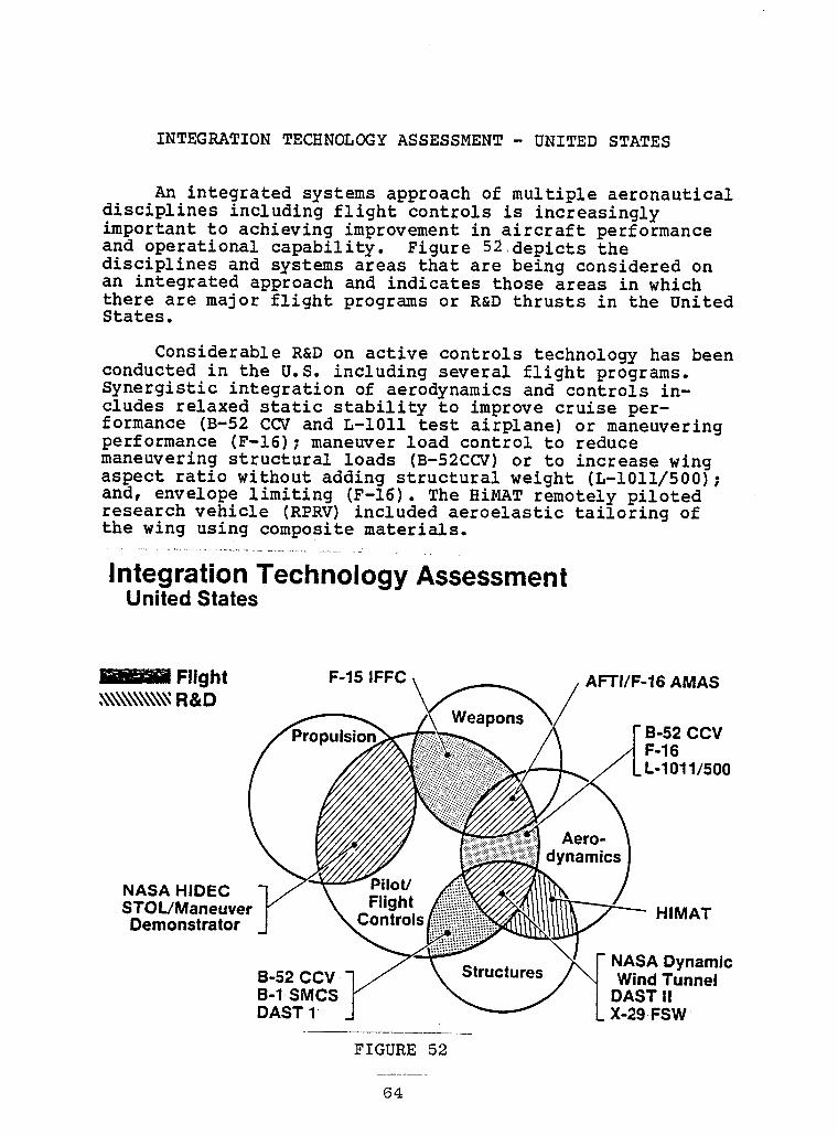
II
INTEGRATION TECHNOLOGY ASSESSMENT- UNITED STATES
!An integratedsystems approach of multiple aeronautical
I disciplinesincludingflight controls is increasinglyimportantto achievingimprovementin aircraft performanceand operationalcapability. Figure 52,depictsthe
I disciplinesand systems areas that are being consideredonan integratedapproachand indicatesthose areas in whichthere are major flight programs or R&D thrusts in the United
i States.ConsiderableR&D on active controls technologyhas been
conductedin the U.S. includingseveral flight programs.
I Synergisticintegrationof aerodynamicsand controls in-cludes relaxed static stabilityto improve cruise per-formance (B-52CCV and L-1011 test airplane)or maneuvering
I performance (F-16);maneuver load control to reducemaneuveringstructuralloads (B-52CCV)or to increasewingaspect ratio without adding structura!weight (L-1011/500);
i and, envelopelimiting (F-16).The HiMAT remotelypilotedresearchvehicle (RPRV)includedaeroelastictailoringofthe wing using compositematerials.
i ................................................Integration TechnologyAssessmentUnited States
!I _ Flight F-15 IFFC AFTi/F-16 AMAS,_\\\\\\\\\\_R&D
I B-52 CCVF-16L-1011/500
!I Aero-
NASA HIDEC
I STOL/Maneuver HIMATDemonstrator
i NASADynamicB-52CCV WindTunnelB-1 SMCS DASTIIDAST1 X-29FSW
I FIGURE 52
Ii
Structuresand control integrationflight programsinclude structuralmode control (B-52 CCV for fatigue ireductionand B-I for ride control);and the DAST-I RPRV •(DAST stands for Drones for Aerodynamicand Structural
i
Testing). Active flutter control involvesthe integrationof aerodynamics,structures,and controls. NASA has iconducted dynamicwind tunnel tests with several modelsincludingflutter of external stores; B-52 CCV flight tests;and, DAST-II supercriticalwing active flutter control. The •X-29 Forward Swept Wing (FSW)technologydemonstratorbeing mdeveloped for DARPA by Grumman Aerospacehas a verydemanding control interactionwith aeroelasticeffects in iwing structuraldivergence,flutter and structural idynamics/controlcoupling.
The integrationof flight and propulsionsystems control iis relativelynew except for conventionalautopilot functions, I
such as Mach holds, and power approach compensators. The R&Dthrusts (e.g.,NASA Highly IntegratedDigital Engine iControls, HIDEC, program) now considermore of the inner loopintegrationto optimize the propulsionsystems performance(adaptivestall margin), and optimize flight path management. •Propulsionand flight controls integrationis of particular mimportancein the type of VSTOL and STOL fighterconfigurationsof current interest to the Air Force. TheSTOL/ManeuverDemonstrator
new initiativeat AFWAL has a major iobjectiveto demonstratethe potentialof integratedflightand propulsioncontrol includingthrust vectoring.
The other major system to be integratedwith flightcontrols is the weapons systems. Significantimprovementsinweapons delivery has been demonstratedon the AFWAL F-15 •IntegratedFlight and Fire Control (IFFC)flight demonstration iprogram. The IFFC system couples the fire control director tothe flight control system to quickly null out trackingerrors iand reduce pilot workload. The joint AF/Navy/NASAAFTI-16 •program is also investigatingthe integrationof flight and
i
fire control but also couples in aerodynamicswith the use ofdirect lift and side force control. That part of the program His called AutomatedManeuveringAttack System (AMAS) (Ref.33).
The Air Force Advanced Tactical Fighter (ATF)program has •directed the seven airframe companiesconductingdefinitionstudies to consider the various integratedsystem concepts
discussed above, i
iI
05 I
!I The subject "systemsintegration"is currentlyvery
popular. Two recent AGARD Guidance and Control Panel Symposia
D focused totally on the subject: "Guidanceand ControlTechnologyfor Highly IntegratedSystems" in Athens, Greece,October 1981 (Ref.34); and, "Integrationof Fire Control,Flight Control, and PropulsionControl Systems" in Toulouse,
H France, May 1983 (Ref.35). Systems integrationis beginningto be considereda disciplinein and of itself. The Air Forceand NASA are sponsoringseveral studies to develop the
B technologybase, e.g., references36 and 37. ConsiderableR&Deffort, includingflight research,is expected over the nextseveral years to develop and validate the design tools and
i benefits.
!!
!!!!!!!!!!H 66
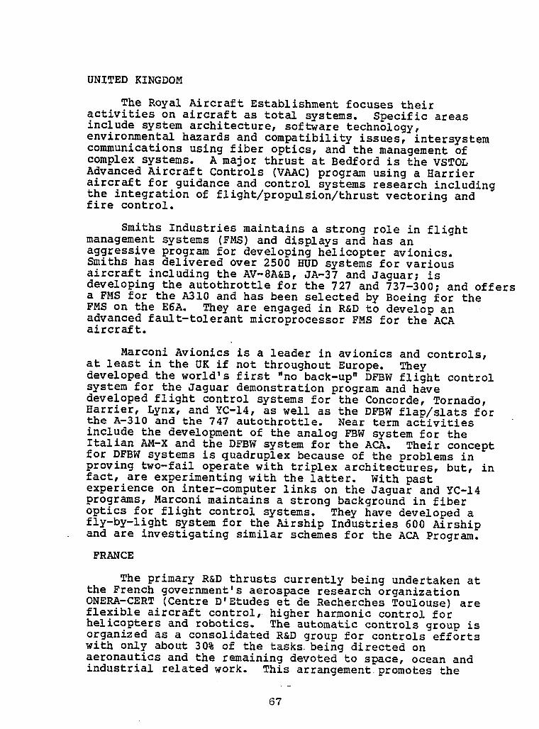
i!
UNITED KINGDOM
Royal Aircraft Establishmentfocuses their nThe
activitieson aircraftas total systems, specific areasinclude system architecture,software technology,environmentalhazards and compatibilityissues, intersystem icommunicationsusing fiber optics, and the management ofcomplex systems. A major thrust at Bedford is the VSTOLAdvanced Aircraft Controls (VAAC)program using a Harrier iaircraft for guidance and control systems researchincludingthe integrationof flight/propulsion/thrustvectoring and
fire control, iSmiths Industriesmaintainsa strong role in flight
management systems (FMS)and displaysand has an msaggressive
program for developinghelicopteravionics, iSmiths has deliveredover 2500 HUD systems for variousaircraft includingthe AV-8A&B, JA-37 and Jaguar; isdevelopingthe autothrottlefor the 727 and 737-300; and offers ia FMS for the A310 and has been selected by Boeing for theFMS on the E6A. They are engaged in R&D to develop anadvanced fault-tolerantmicroprocessorFMS for the ACA •aircraft. |
Marconi Avionics is a leader in avionics andat least in the UK if not throughoutEurope. Theyc°ntr°ls' "idevelopedthe world's first "no back-up"DFBW flight control
mm
system for the Jaguar demonstrationprogram and havedevelopedflight control systems for the Concorde,Tornado, BHarrier, Lynx, and YC-14, as well as the DFBW flap/slatsforthe A-310 and the 747 autothrottle. Near term activitiesinclude the developmentof the analog FBW systemfor the •Italian AM-X and the DFBW system for the ACA. Their concept mfor DFBW systems is quadruplexbecause of the problems inproving two-fail operatewith triplex architectures,but, in ifact, are experimentingwith the latter. With past iexperienceon inter-computerlinks on the Jaguar and YC-14programs,Marconi maintains a strong backgroundin fiberoptics for flight control systems. They have developeda nfly-by-lightsystemfor the Airship Industries600 Airshipand are investigatingsimilar schemes for the ACA Program.
FRANCE N
The primary R&D thrusts currentlybeing undertakenat •the French government'saerospaceresearch organization iONERA-CERT (CentreD'Etudes et de RecherchesToulouse) areflexible aircraft control, higher harmonic control forhelicoptersand robotics. The automaticcontrols group is norganizedas a consolidatedR&D group for controls effortswith only about 30% of the tasks being directed onaeronauticsand the remainingdevoted to space, ocean and •industrialrelatedwork. This arrangementpromotes the
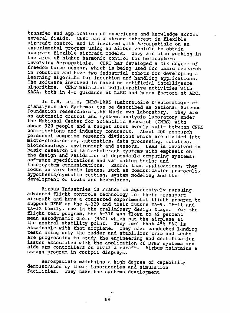
transfer and applicationof experienceand knowledgeacrossseveral fields. CERT has a strong interest in flexibleaircraft control and is involvedwith Aerospatialeon anexperimentalprogram using an Airbus vehicle to obtainaccurateflexible aircraftmodels. They are also working inthe area of higher harmonic controlfor helicoptersinvolvingAerospatiale. CERT has developeda six degree offreedom force sensor,which is being used for basic researchin roboticsand have two industrialrobots for developingalearning algorithmfor insertionand handling applications.The software involved is based on artificialintelligencealgorithms. CERT maintains collaborativeactivitieswithNASA, both in 4-D guidanceat LaRC and human factors at ARC.
In U.S. terms, CNRS-LAAS (LaboratoireD'AutomatiqueetD'Analysisdes Systems) can be describedas National ScienceFoundationresearcherswith their own laboratory. They arean automatic control and systems analysislaboratoryunderthe National Center for ScientificResearch (CNRS)withabout 320 people and a budget about evenly split between CNRScontributionsand industry contracts. About 200 researchpersonnelcomprise researchdivisionswhich are divided intomicro-electronics,automatics,data processing,robotics,biotechnology,environmentand sensors. LAAS is involvedinbasic researchin fault-tolerantsystems with emphasisonthe design and validationof dependablecomputingsystems;software specificationsand validationtools;andintersystemcommunications. Rather than applications,theyfocus on very basic issues, such as communicationprotocols,hypothesis/symbolictesting, system modeling and thedevelopmentof tools and techniques.
Airbus Industriesin France is aggressivelypursuingadvancedflight controls technologyfor their transportaircraft and have a concertedexperimentalflight program tosupport DFBW on the A-320 and their future TA-9, TA-II andTA-12 family, now in the preliminarydesign stage. For theflight test program, the A-310 was flown to 42 percentmean aerodynamicchord (MAC)which put the airplane atthe neutral stabilitypoint. They feel that 45% MAC isattainablewith that airplane. They have conductedlandingtests using only the rudder and stabilizertrim and testsare progressingto study the engineeringand certificationissues associatedwith the applicationof DFBW systemsandside arm controllerson civil aircraft. Airbus maintainsastrong program in cockpit displays.
Aerospatialemaintainsa high degree of capabilitydemonstratedby their laboratoriesand simulationfacilities. They have the systems development
68
ii
responsibilityfor Airbus. Their DFBW design concepts forthe A-320 manifests an understandingof the issues involved •as exhibitedby the advanced architectureand verification imethods applied.
WEST GERMANY iDFVLR (DeutscheForschungs-undVersuchsanstaltfur
Luft-und Raumfahrt)maintains an excellentR&T base activity ifor flight researchapplications,includingresearch inreconfigurablecontrolsfor transportaircraft,sensoranalyticalredundancy,and digital actuators. Two BO-105 •helicoptersare currentlybeing used in R&D activities- one idevoted to DFBW experimentation,includingside stickcontrol,and the other involved in cockpit-crewinterface i
systems researchwith emphasison night operations. A major inew thrust is ATTAS, which is a highly integratedflightresearch program involvingair traffic control/flightmanagement systems; crew interfaceand automation;and, DFBW itechnologyincludingredundancymanagementand faulttolerance. A ground system is includedto provide afacility for simulatingthe total ground/airborne •environment. A VFW 614 will serve as a test bed aircraft Imodified initiallywith a single string digital channelusing a Rolm computer. ..
IiiiiIiii
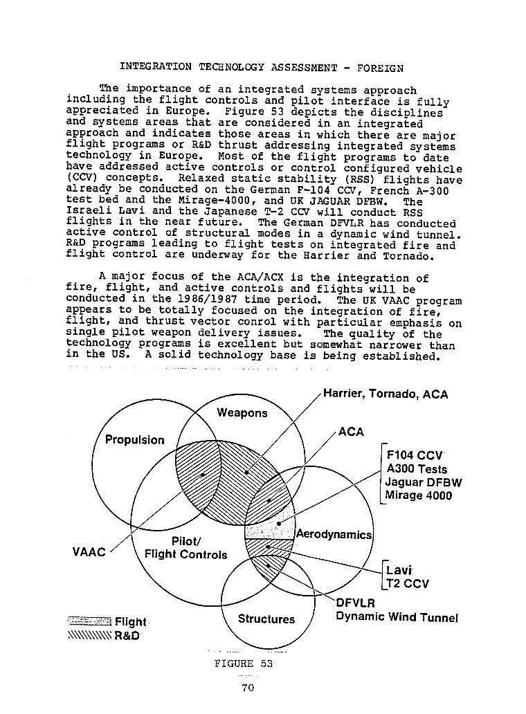
II INTEGRATIONTECHNOLOGYASSESSMENT- FOREIGN
The importanceof an integratedsystems approachI includingthe flight controls and pilot interfaceis fully
appreciatedin Europe. Figure 53 depicts the disciplinesand systems areas that are consideredin an integrated
I approach and indicatesthose areas in which there are majorflight programs or R&D thrust addressingintegratedsystemstechnologyin Europe. Most of the flight programsto date
i have addressedactive controlsor control configuredvehicle(CCV)concepts. Relaxed static stability (RSS)flights havealready be conductedon the German F-104 CCV, FrenchA-300test bed and the Mirage-4000,and UK JAGUAR DFBW. The
I Japanese CCV will conduct RSSIsraeli Lavi and the T-2flights in the near future. The German DFVLR has conductedactive control of structuralmodes in a dynamic wind tunnel.
I R&D programs leading to flight tests on integratedfire andflight control are underwayfor the Harrier and Tornado.
I A major focus of the ACA/ACX is the integrationoffire, flight, and active controls and flights will beconductedin the 1986/1987time period. The UK VAAC program
I appears to be totally focused on the integrationof fire,flight, and thrustvector conrolwith particularemphasisonsingle pilot weapon delivery issues. The quality of thetechnologyprograms is excellentbut somewhat narrower than
I in the US. A solid technologybase is being established.
I Tornado, ACAHarrier,
Weapons
i PropulsionF104 CCV
I A300 TestsJaguar DFBW
i Mirage 4000
Pilot/I VAAC Flight Controls
I Lavi:T2 CCV
L.R
I !__:_-_i:::_=_+_+_tFlight Structures Dynamic Wind Tunnel_\\\\\\\\\\_R&D
I ..............
FIGURE 53
| 7o

IIIIIIIIIIIIIIIIIII

IIIIIiI GENERAL OBSERVATIONS
! AND
II SUMMARY"
IIIIIIII
71
I

IIIIIIIIIIIIIIIIIII
!OBSERVATIONSAND SUMMARY
I,The survey of flight crucial flight controlstechnology
indicatesthat the era of digital-fly-by-wire(DFBW)
I applicationshas begun both in the U.S. and Europe. Thenewestmilitary aircraft,being developedfor the mid to late1980s first flight,will have DFBW or possibly digital-fly-
I by-light (DFBL),most of which will retain some form ofelectricalback-up system. The flight safety.reliabilitygoal for these systems is generallyabout i0-" failuresper
i flight hour. Most of these military aircraftwillincorporateflight crucial active controls functions,e.g.,relaxed or negative static stability. The French seem to bethe closest to committingto DFBW and relaxedstatic
l stabilityfor a commercialtransport.
The technologywith potential to achieve 10-9 failures
I per a i0 hour flight reliabilityperformancein a pure DFBWwith no back-up system is still in the advancedR&D stage.The techniquesand tools to design,verify, validate,and
I assure reliabilityfor such systems is still beingdeveloped.
Highly integratedsystems technologyseems to be theI most importantcurrentR&D thrust
with flight crucial flightcontrolsbeing at the core of such systems. Increasedemphasishas been placed on improvingreliability,
l maintainability,and survivabilityto assure highavailabilityand dispatch reliabilityrather than justincreasedperformance.
I The survey clearly indicatesthat the Europeansarecompetitivewith the U.S. Funding constraintstend to limit
l the breadth of work but in the areas pursued they are highlycompetentand at the leading edge of technology. The U.S.still appears to lead the technologyin flight research anddevelopmentprogramsbut the gap is closing. There is a
I formidablesystems technologybase in Europe from which theU.S. can learn. It is clear that Europe is relying heavilyon U.S. microelectronicstechnology. There is definitelya
l trend towardsmultinationalventures in advanced technologyand developmentprograms.
!!!

II
,IIIIIIIII!IIIIIII

IIIIIIIII . . -
" REFERENCES& BIBLIOGRAPHY-| "
!!!!!!!!II _3

IIIIIIIIIIIIIIIIIII
REFERENCES _
li. Anderson, C.A.: F-16 MultinationalFighter,AGARD-AG-234, November 1978.
2. Harschburger,H. E. and Moomaw, R. F.: Experiencewith
i the F/A-18 Digital Flight Control System,5th DigitalAvionics Conference,Seattle,WA, November1983.
l 3. Nelson, W. E., Jr.: F-20 TigersharkFlight ControlSystem Developmentand FlyingQualities Review,SAE AerospaceControl and Guidance CommitteeMeeting,
l Seattle,WA, March 1983.4. Lee, H. F.: Testing BITE on Boeing 757/767 in a Simu-
lated OperationalEnvironment,5th Digital Avionicsl Conference,Seattle,WA,
November 1983.
5. Devlin, T., et al: DC-9 Super 80 Digital Flight
l Guidance System, SAE C&G Committee,February1982.6. Poupard,R. E. and Sheridan,C. T.: Space Shuttle
I Applications,AGARDographNo. 258, May 1980.7. Eslinger,R. C.: Fail-operationalDAFCS for Business/
CommuterAircraft, SAE Paper 830714 PresentedatI Business Aircraft Meeting
and Exposition,Wichita,KS, April 1983.
l 8. Corney, J. M.: Developmentof Multiple RedundantFlight Control Systemsfor High IntegrityApplications,AeronauticalJournal, 1980.
l 9. Brady, T, V.: Assessmentof Advanced Flight ControlSystems Reliability& MaintainabilityDesign,
l Qualification& MaintenanceRequirements,USAAVRADCOMTR-82-D-I,May 1982.
i0. Landy, R. J., et al: IntegratedFlight and Fire
l Control, Presentedat the AIAA G&C Conference,San Diego, CA, August 1982.
l Ii. Mackall, D. A., et al: Qualificationof the FlightCriticalAFTI/F-16Digital Flight Control System,AIAA 21st Aerospace ScienceMeeting,•Reno, NV,
i January 1983.
!!
12. Hills, A. D.: A310 Slat and Flap Control SystemManagementand Experience,5th Digital Avionics •Conference,Seattle,WA, November 1983. |
13. Korte, U.: Flight Test Experiencewith a DigitalIntegratedGuidance and Control System in a CCV •Fighter Aircraft, AGARD CP 321, Lisbon, Portugal,
n
October 1982.
14. Smith, T. D., et al: Ground & Flight Testing on the NFly-By-WireJaguar Equippedwith a Full Time Quad-ruplex Digital IntegratedFlight Control System, •AGARD CP 321, Lisbon, Portugal,October 1982.
15. Marshall, R. E. W., et al: Jaguar Fly-By-Wire •DemonstratorIntegratedFlight Control System, 1981 |Advanced Flight Control Symposium;Colorado Springs,CO, August 5-7, 1981.
16. Daley, E. and Smith, R. B.: Flight Clearanceof the nJaguar Fly-By-WireAircraft,Royal AeronauticalSocietySymposium,April 27, 1982. n
17. Chun, R. K.: ARINC 429 Digital Data Communicationsonthe Boeing 757 and 767 CommercialAirliners,4th •Digital Avionics Systems Conference,St. Louis, MO, |November 1981.
18. Bondy, J. & Weaver, R.: Bus Schedule Change Issues in Nthe 0n-BoardDistributedData System, 5th DigitalAvionics Systems Conference (DASC),Seattle,WA,November 1983. N
19. Bennett, D. B.: The V Bus Family: Candidate forCommon Use with VLSI Technology,5th Digital mAvionics Systems Conference (DASC),Seattle,WA, |November 1983.
20. Leonard, W. B. & Chow, K. K.: A New Bus Architecture Nfor DistributedAvionic Systems,5th Digital
m
Avionics Systems Conference (DASC),Seattle,WA,November 1983. n
m
21. Brock, L. D. & Hopkins, A. L. Jr.: On-boardCommunicationsfor Active Control Transport •Aircraft, 4th Digital Avionics Systems Conference (DASC), |St. Louis, MO, November 1981.
22. Fraser, D. C. and Deyst, J. J.: A Fault-Tolerant nArchitectureApproach to Avionics Reliability
n
Improvement,AGARD-CP-261,October 1979.
I
!23. Cunningham,T. B. & Poyneer, R. D.: Sensor Failure
l DetectionUsing AnalyticalRedundancy,Proceedingsofthe Joint AutomaticControl Conference,San Francisco,CA, June 1977.
l 24. Burns, R. C.: MultifunctionInertial ReferenceAssembly (MIRA),Final TechnicalReport,AFFDL-TR-78-105,September1978.
l 25. Leudde, W. J.: The use of SeparatedMultifunctionalInertial Sensors for Flight Control,4th DigitalAvionics Systems Conference (DASC),St. Louis, MO,
l November1981.
26. Sebring, D. L.: RedundancyManagementof Skewed &
I DispersedInertial Sensors,4th Digital AvionicsSystems Conference (DASC),St. Louis, MO, Nov. 1981.
l 27. Weinstein,W.: Deploymentof an Advanced Skewed SensorElectronic (ASSET)System for Flight Control,GrummanAerospace Corporation,Report NADC 76295-30,
i October 1976.28. Toolan, W. K. & Zislin, A. M.: Development&
LaboratoryTest of an IntegratedSensory System (ISS)I for Advanced Aircraft,4th Digital Avionics SystemsConference (DASC),St. Louis, MO, November 1981.
I 29. Wensley, J. H., et al: SIFT - The Design and Analysisof a Fault Tolerant Computerfor Aircraft Control,Proceedingsof the IEEE, Vol. 66, No. 10,
l October 1978.30. Hopkins, A. L., Smith, T. B. & Lola, J. H.: FTMP -
A Highly Reliable Fault-TolerantMultiprocessorfor
l Aircraft, Proceedingsof the IEEE, Vol. No.66, i0,October 1978.
l 31. White, J. et al: A Multi-MicroprocessorFlight ControlSystem, AFWAL-TR-81-3044,May 1981.
i 32. Driscoll,K.: Multi-MicroprocessorFlight ControlSystem, 1982, 5th Digital Avionics Conference,SeattleWA, November 1983.
I Col.,andSwortzel,F. R.: AFTI/F-16-33. Bianco, A. J., Lt.
An integratedSystemApproach to Combat Automation,5thDigital Avionics Systems Conference (DACS),Seattle,
I WA, November1983.34. AGARD ConferenceProceedingsNo. 314, Athens, Greece
l October 1981.
35. AGARD ConferenceProceedingsNo. 349, Toulouse, FranceMay 1983.
36. Stern,A. D.; IntegratedAirframe/PropulsionControlSystem Architectures(IAPSA)Study, AIAA Guidance andControl Conference, Paper No. 83-2158,August 1983.
37. Joshi, D. S., et al; A Design Approach toIntegratedFlight and PropulsionControl, SAE IAerospace Congress and Exposition,Paper No. 831482,October 3-6, 1983.
l
lII
I B IBL IOGRAPHY
l This bibliography is not intended as an exhaustiveliterature search on the topics outlined, but rather as a listingof pertinent documents available to the authors during the course
l of the study. Thus, neither the inclusion nor omission of aparticular document reflects on its importance or significance.
I. FLIGHT CONTROL SYSTEMS
I Advanced Digital Optical Control System (ADOCS),IndustryBriefing,August 17, 1983
l Aircraft Flight Control Technology,Flight CriticalSystems,Tri-serviceTopical Review, May 1982
I Technical Description, F-16 Air Combat Fighter Vol. 8,Flight Control System, General Dynamics FIG. 060-8,
l August 1975Abrams, C.: ExploratoryDevelopmentPrograms- FlightControl Systems,Briefing for SAE, Nov. 4, 1982
I Anderson, C. A. : F-16 Multinational Fighter, AGARD-AG-234,November 1978
I Corney, J. M. : Development of Multiple Redundant FlightControl Systems for High Integrity Applications,
i AeronauticalJournal, 1980Comegys, G. L. & Hanson, G. R.: IntegratedFlightTrajectoryControlDevelopmentProgram,AFWAL-TR-81-3077,
I August 1981Daley, E. and Smith, R. B.: Flight Clearanceof the Jaguar
I Fly-By-WireAircraft,Royal AeronauticalSociety Symposium,April 27, 1982
Devlin, T., et al: DC-9 Super 80 Digital Flight Guidancel System, SAE C&G Committee,February 1982
Driscoll, K.: Multi-MicroprocessorFlight Control System,l 1982, 5th Digital Avionics Conference,Seattle,WA.,November1983
l Eslinger,R. C.: Fai!-OperationalDAFCS for BusinessCommuterAircraft,SAE TechnicalPaper 830714,April 1983
l Fuller, J. W. & Vincent, J. H.: AdvancedV/STOL FlightContro! System TechnologyAssessment,Systems ControlTechnology,ReportNo. 5339-250-1,May 1982!
m .....
78
!
iI. FLIGHT CONTROL SYSTEMS (Continued) i
Harris, T. M.: Adaptive Flutter Suppressionfor iTactical Fighters CarryingExternal Stores,Briefing FDL 11-1-28-8,December 1982
i
Harschburger,H. E. & Moomaw, R. F.: Experiencewith Hthe F/A-18 Digital Flight Control System, 5th DigitalAvionics Systems Conference,November 1983, Seattle, iWA |Hartmann,G. L.: Advanced Flight Control SystemStudy, NASA CR 163117, November 1982 ii
Hendrick,R., et al: Digitac II Digital FlightControl System Advanced TechniquesEvaluation, iAFFDL-TR-79-3140,December 1979
Hills, A. D.: A310 Slat and Flap Contro! System •Managementand Experience,5th Digital Avionics mConference,Seattle,WA, November1983
Korte, U.: Flight Test Experiencewith a Digital HIntegratedGuidance and Control System in a CCV
w
Fighter aircraft,AGARD, CP 321, Lisbon, Portugal,October 1982 H
i
Mackall, D. A.: AFTI-16 Digital Flight ControlSystem Experience,NASA CP 2296, October 1983
Mackall, D. A., et al: Qualificationof the FlightCriticalAFTI/F-16 Digital Flight Control System, mAIAA 21st AerospaceScience Meeting, Reno, NV, BJanuary 1983
Marshall,R. E. W., et al: Jaguar Fly-By-WireDemonstratorIntegratedFlight Control System, 1981Advanced Flight Control Symposium,Colorado Springs,CO, August 5-7, 1981 H
McGough, J. G., et al: Advanced Flight Control SystemStudy,NASA CR 163120, November 1982 •
McKinlay,W. H.: Some Aspects of Flight TrajectoryControl In Future Avionics Systems for CombatAircraft,AGARD CP 349, Toulouse,France, May 1983 ii
Nelson, W. E., Jr.: F-20 TigersharkFlight ControlSystem Deve!opmentand Flying QualitiesReview, SAE •AerospaceControl and Guidance CommitteeMeeting,Seattle,WA, March 1983
!........ i
79
i
I I. FLIGHT CONTROL SYSTEMS (Continued)
I Niven, A. J.: Heavy Lift HelicopterFlight ControlSystem, USAAMRDL-TR-77-40A,September1977
I Ostgaard,M. A.: Flight Control System Development,Past 25 Years and Next 25 Years Prediction,Briefingfor SAE, 4 November1982
I Pope, R. E.: Another Look at Guidance & Control,Briefing at G&C Panel Symposium,Ottawa, Canada,May 1979
I Schoenman,R. L.: 767 Flight Control System,SAE C&G Committee,February 1982
I Smith, T. D., et al: Ground and Flight Testing on theFly-By-WireJaguar Equippedwith a Full Time QuadruplexDigital IntegratedFlight Control System, AGARD CP 321,
I Lisbon, Portugal,October 1982
Szalai, K. L., et al: Digital Fly-By-WireFlightI ControlValidation Experience,NASA Technical
Memoran-dum 72860, December 1978
I Szalai, K. L., et al: Design & Test Experiencewith aTriply RedundantDigital Fly-By-WireControl System,AIAA Paper No. 76-1911,August 1976
I White, J., et al: A Multi-MicroprocessorFlight ControlSystem, AFWAL-TR-81-3044,May 1981
I Young J. T. Capt. et al: &Design Deve!opmentt of ther
MultifunctionFlight Control ReferenceSystem,AGARD CP 349, Toulouse,France, May 1983
I II. INTEGRATEDSYSTEMS
i FunctionalIntegration,Panel Point Paper, NASA/DODTopical Review, May 20, 1982
IntegratedApplicationof Active Controls (IAAC)I Technology Advanced Subsonic TransportProject -
To AnTest ACT System Description,NASA CR 172221,December 1983
I Bangert, L. H., et al: Study of IntegratedAirframe/Propulsion Control System Architectures, Contract
I NASI-16896,March 1983Bianco, A. J., Lt. Col. & Swortzel,F. R.: AFTI/F-16-An IntegratedSystem Approach to Combat Automation,5th
I Seattle,WA, November1983DACS,
80
I
III. INTEGRATEDSYSTEMS (Continued)
Burcham, F. W., et al: Flight Evaluationof Modifica- itions to a Digital ElectronicEngine Control SystemIn An F-15 Airplane,NASA TM 83088, Prepared for 21st
Aerospace Science Conference,Reno, NV, January 1983 iFraedrich,W. M.: Integrationof Fire, Flight &PropulsionControl Systems,An Overview,Retrospective •and Prospective,AGARD CP 349, Toulouse,France, May1983
Joshi, D. S., et al: A Design Approach to Integrated iFlight and PropulsionControl, SAE Aerospace Congressand Exposition,Paper No. 831482, October 3-6, 1983
Landy, R. J., et al: IntegratedFlight and Fire iControl, presented at the AIAA G&C Conference,
San Diego, CA, August 1982 iLandy, R. J., et al: IntegratedFlight & Fire ControlDemonstrationof An F-15B Aircraft: System Development •& Ground Test Results, AGARD CP 314,Athens, Greece, |October 1981
l
Rambach, D.: RelationsBetween Engine Digital Control •& Other Aircraft Systems,Briefing at G&C 36th I
Symposium,May 1983
Seabridge,A. G. & Edwards, R. A.: IntegratedPower BPlant Control Systems & PotentialPerformanceBenefits,
AGARD CP 349, Toulouse,France, May 1983 ii
Stern, A. D. & Carlin, C. M.: Study of IntegratedAirframe/PropulsionControl SystemArchitectures, iContractNAS1-16942,March 1983 •
III. FAULT TOLERANCE & RELIABILITY
Fault ToleranceDesign & RedundancyManagementTechni- iques, AGARD-LS-109,September1980
Avizienis,A.: Fault-Tolerance: The Survival HAttribute of Digital Systems,Proceedingsof IEEE,Vol. 66, No. I0, October 1978 i
Bannister,J. A., et al: ProblemsRelated to theIntegrationof Fault Tolerant Aircraft Electronic
Systems, NASA CR 165926, June 1982 IiBrady, T. V.: Assessmentof Advanced Flight ControlSystems Reliability& MaintainabilityDesign, Qualifi- •cation & MaintenanceRequirements,USAAVRADCOMTR-82-D-!,May 1982
I
l III. FAULT TOLERANCE& RELIABILITY(Continued)
I Bryant, L. A. & Stiffler,J. J.: Care III Phase IIReport MaintenanceManual, NASA CR 165863,September1982
I Bryant, L. A. & Stiffler,J. J.: Care III Phase IIReport User's Manual, NASA CR 165864, September1983
l Bryant, L. A. & Stiffler,J. J.: Care III Phase IIReport Math Description,NASA CR 163566,November1982
l Fickeisen,F. C.: FAA Certificationof B757/67 AvionicSoftware,SAE C&G Committee,March 9, 1983
I Hecht, M. & Hecht, H.: Fault Tolerant Modules forSIFT, NASA CR 165874, July 1982
l Laprie, J. C.: DependableComputingIn Europe,Journal of the InformationProcessingSociety of Japan,April 1982
I Lamport, L., et al: The ByzantineGenerals Problem,ACM Transactionson ProgrammingLanguagesand
l Systems, Vol. 4, July 1982Melliar-Smith,P. M., & Lamport, L.: Synchronizing
i Clocks in the Presenceof Faults, SRI International,July 1981, Rev. March 1982
Nagel, P & Skrivan, J. A.: Software Reliability:I Experimentation& Modeling,NASA
RepetitiveRunCR-165836,February 1982
l Rose, D. M., et al: Review & Verificationof Care IIMath Model & Code, NASA CR 166096, April 1983
l Rose, J.: Cost and Benefits Design OptimizationModelfor Fault TolerantFlight Control Systems,NASACR 159281, August 1982
I & Liebergot,H. L.: Fault ToleranceofSedmark, R. M.A General Purpose Computer Implementedby Very LargeScale Integration,IEEE Transactionson Computers,
I Vol. C-29 No. 6, June 1980Sisar, M. : Design of Analytical Failure Detection
I Using SecondaryObservers,NASA TM-84284,August 1982Stiffler,J. J., et al: Care III Phase II Report Testand Evaluation,NASA CR 163631, November 1982!
I .......
82 _
!
IIII. FAULT TOLERANCE & RELIABILITY (Continued) |
iSzalai, K. J.: Flight Experiencewith Flight ControlRedundancyManagement,AGARD-LS-109,October 13-21,
1980 LIV. RECONFIGURABLECONTROLS
i
Self-RepairingDigital Flight Control System Study; iInterim Report for AFFDL by GE, Binghamton,NY;
May 1983 iBerman, H. L., and Boudreau, J. A.: Dispersed andReconfigurableDigital Flight Control System Study,AFFDL-TR-79-3125,Grumman Aircraft Company, December |1979 |
Chandler, P. R.: Self RepairingFlight Control System iReliabilityand MaintainabilityProgram Plan; Industry iBriefing by AFWAL, Feb. 9, 1984
Cunningham,T. B.: Failure ManagementTechniquesfor i
i
High Survivability,AGARD Lecture Series 109, FaultToleranceDesign and RedundancyManagementTechniques,
March 1981Howell, W. E., et al: RestructurableControls,NASA
ConferencePublication#2277 September1982 IL
McGough, et al: Digital Flight Control System Redun-dancy Study, AFFDL-TR-74-83,The Bendix Corporation, iJuly 1974 lNess, W. G.: IntegratedAssurance Assessmentof aReconfigurableDigital Flight Control System, |NASA CR 170281, April 1983
V. ACTIVE CONTROLS i
Active Flutter SuppressionUsing Optical OutputFeedback Digital Controllers,NASA CR 165939, iMay 1982 iDevelopmentand Flight Evaluationof an Augmented []
Active Control Concept,NASA CR 166009, iStabilityNovember 1982
IntegratedApplicationof Active Controls (IAAC) iTechnologyto an Advanced Subsonic TransportProject,NASA CR 3519, Feb 1982
SelectedAdvanced Aerodynamicand Active Control iConcepts Development,NASA CR 3469, October 1981
I
V. ACTIVE CONTROLS (Continued)
Chipman, R. R., et al: Active Control of AeroelasticDivergence,AIAA A82-30151,May 1982
Guinn, W. A.: Developmentand Flight Evaluationof anAugmentedStabilityActive Controls Concept,NASACR 166009, November 1982
Lapins, M., et al: Piloted SimulatorEvaluationofRelaxed Static StabilityFighter at High Angle-of-Attack, AIAA Paper 82-1295,August 1982
I VI. COMPUTERS
I Butler, R. W.: An Assessmentof the Real-TimeApplica-tion Capabilitiesof the SIFT Computer System,NASA TM 84482, April 1982
I Hopkins, A. L., et al: FTMP - A Highly Reliable Fault-Tolerant Multiprocessorfor Aircraft, Proceedingsofthe IEEE, Vol. 66, No. 10, October 1978
I Melliar-Smith,P. M.: HierarchicalSpecificationofthe SIFT Fault-TolerantFlight Control System,
I SRI TR CSL-123,March 1981Shapiro,A. J.: Advanced Design & PerformanceOptimi-
zation TechniquesUtilized to Develop the F-IllWeapons/NavigationComputer (WNC),AGARD CP 321,Lisbon, October 1982
Smith, T. B. et al: A Fault-TolerantMicroprocessorArchitecturefor Aircraft, Interim Report NASACR 165911, 1978
Wensley, J. H.: Design Study of SIFT Computer,NASA CR 3011, June 1982
Wensley, J. H., et al: SIFT - The Design and Analysisof a Fault Tolerant Computerfor Aircraft Control,Proceedingsof the IEEE, Vol. 66, No. 10, October 1978
l VII. DATA BUSSING
l Bennett, D. B.: The V Bus Family: CandidateforCommon Use with VLSI Technology,5th Digital AvionicsSystems Conf (DASC), Seattle, WA, November 1983
l Bondy, J. & Weaver, R: Bus Schedule Change Issues inthe On-Board DistributedData System, 5th DigitalAvionics Systems Conf (DASC),Seattle,WA,
l November 1983
m ....
84
!
VII. DATA BUSSING (Continued)
L. D. & Hopkins, A. L., Jr.: On-board Communi- IBrock,cations for Active Control TransportAircraft, 4thDigital Avionics Systems Conf. (DASC), St. Louis,
MO, November 1981 Li
Chun, R. K.: ARINC 429 Digital Data Communicationsonthe Boeing 757 and 767 CommercialAirliners,4th iDigital Avionics Systems Conference,St. Louis, MO, INovember 1981
Fraser, D. C. and Deyst, J. J.: A Fault-Tolerant iArchitectureApproach to Avionics ReliabilityImprove-ment, AGARD-CP-261,October 1979
BLeonard, W. B. & Chow, K. K.: A New Bus Architecture |for DistributedAvionic Systems,5th Digital Avionics
Systems Conf (DASC),Seattle,WA, November 1983 IRelis, M. J. & Urbanik, T. J.: A Fiber Optic Receiverfor a Digital Data Link in the AV-8B Aircraft, |AIAA Paper 81-2269, November 1981 ISynder, F. B.: Control Media MechanizationStudy,
USAAVRADCOMTR-81-D-31,May 1982i
Snyder, F. B. & Giri, R. R.: Fiber Optic Technologyfor Data Transmissionin the HelicopterEnvironment, |AHS Preprint A-81-37-II-2000,May 1981 i
VIII. ACTUATIONSYSTEMS iL
Airplane ActuationTrade Study, Boeing Briefingto IndustryReps, November 13, 1979 |ElectricallyCommandedActuationControls,HR Textron |Briefing to Boeing, April 1978
SOA Flight Control Actuatorsfor Helicopters, iHR Textron Briefingto Bell Helicopter,August 12, 1982
i
Guinn, K. F.: Advanced Rotor Actuation Concepts, IUSAAVRADCOMTR-82-D-21,December 1982
T. S. & Mattos, F.: General Developmentof ISelna,Flight Control ActuationSystems in the U.K.,SAE A-6 CommitteeMeeting,April 28, 1982
[]
Wyllie, C. E.: Are Actuation Systems Ready for all iElectricAero Spacecraft,Drives & Controls Interna-tional, April/May1982 i
i
l8s i
IX. SENSORS AND TRANSDUCERS
Burns, R. C.: Multifunction Inertial ReferenceAssembly (MIRA), Final Technical Report, AFFDL-TR-78-105, September 1978
Caglayan,A. K. & Lancraft, R. E.: An Aircraft SensorFault Tolerant System,NASA CR 165876, April 1982
Cunningham,T. B. & Poyneer, R. D.: Sensor FailureDetectionUsing AnalyticalRedundancy,Proceedingsofthe Joint AutomaticControl Conf., San Francisco,CA,
I June 1977Flynn, S. W. & Smoot, B. J.: Development& Testing ofA Digital/OpticalLinear PositionTransducer,
I USAAVRADCOMTR-83-D-3,July1983
Leudde, W. J.: The Use of SeparatedMultifunctional
I nertial Sensors for Flight Control,4th DigitalAvionics Systems Conf. (DASC),St. Louis, MO,November 1981
I Sebring,D. L.: RedundancyManagementof Skewed &DispersedInertial Sensors,4th Digital Avionics
i Systems Conf. (DASC),St. Louis, MO, November 1981Toolan, W. K. & Zislin, A. M.: Development&LaboratoryTest of an IntegratedSensory System (ISS)
I or Advanced Aircraft,4th Digital Avionics SystemsConf. (DASC),St. Louis, MO, November 1981
I Weinstein,W.: Deploymentof an Advanced Skewed SensorElectronic (ASSET)System for Flight Control, GrummanAerospace Corporation,Report NADC 76295-30,
I October 1976X. MISCELLANEOUS
I lake, B.: Research Opportunitiesfor Rotorcraft,NASA CP 2296, October 1983
I rawford,C. C., Jr.: JVX, What An Opportunity,Vertiflite,July/August1982
I Cunningham,T. B.: Opportunitiesfor Aircraft ControlsResearch,NASA CP 2296, October 1983
Flynn, G. R.: Future Flight ManagementSystems,I DOC. NO. DG-51481TN,Boeing
CommercialAirplaneCompany, May 1982
I 'Avino,D. S. & Spiegel, S. S.: LHX AvionicsArchi-tecture,TechnicalReport by SEMCOR Inc., underContractDAAK80-79-C-0258,February1981
I ........86
I
IX. MISCELLANEOUS(Continued)
Iliff, K. W. & Maine, R. E.: PracticalAspects of iModeling AircraftDynamics from Flight Data,NASA CP 2296, October 1983
Lambregts,A. A.: FunctionalIntegrationof VerticalFlight Path and Speed Control Using Energy Principals,
NASA CP 2296, October 1983 ii
Landis, K. H. & Aiken, E. W.: Assessmentof VariousSide Stick Controller/Stability& Control Augmentation •Systems for Night NOE Flight Using Piloted Simulation, iPresentedat 38th Annual AHS Meeting, Palo Alto, CA,
April 14, 1982 iBLee, H. F.: Testing BITE on Boeing 757/767 in a Simu-
lated OperationalEnvironment,5th Digital Avionics
Conference,Seattle,WA, November 1983 iuMarner, G. R. & Pruyn, R. R.: LHX System Design forImprovedPerformanceand Affordability,Presentedat i8th European RC Forum, September1982 iMeyer, G.: Non-LinearSystems Approach to Control •System Design, NASA CP 2296, October 1983 iPoupard, R. E. & Sheridan,C. T.: Space Shuttle
Applications,AGARDographNo. 258, May 1980 Ii
Schneider,J. J.: History of V/STOL Aircraft Part II,
VertiflightMay/June1983 iWernicke, R. K. & Fischer, J. N.: EvaluationofAdvanced RC Configurationsfor Emerging Military •Applications,Presentedat 37th Annual Forum of AHS, !May 1981
IIiiii
87 i
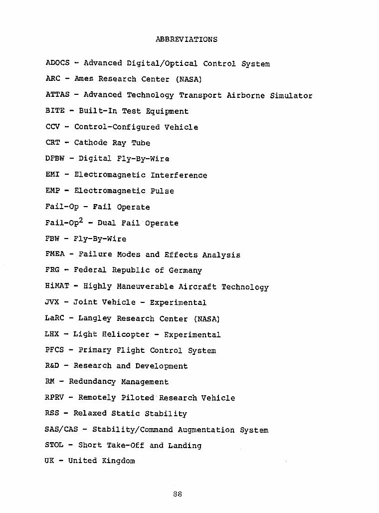
ABBREVIATIONS
ADOCS - Advanced Digital/OpticalControl System
ARC - Ames Research Center (NASA)
ATTAS - Advanced TechnologyTransportAirborne Simulator
BITE - Built-In Test Equipment
CCV - Control-ConfiguredVehicle
CRT - Cathode Ray Tube
DFBW - Digital Fly-By-Wire
EMI - ElectromagneticInterference
EMP - ElectromagneticPulse
Fail-Op - Fail Operate
Fail-Op2 - Dual FailOperate
FBW - Fly-By-Wire
FMEA - Failure Modes and Effects Analysis
FRG - Federal Republic of Germany
HiMAT- Highly ManeuverableAircraft Technology
JVX - Joint Vehicle - Experimental
LaRC - Langley ResearchCenter (NASA)
LHX - Light Helicopter- Experimental
PFCS - Primary Flight Control System
R&D - Research and Development
RM - RedundancyManagement
RPRV - Remotely Piloted ResearchVehicle
RSS - Relaxed Static Stability
SAS/CAS - Stability/CommandAugmentationSystem
STOL - Short Take-Off and Landing
UK - United Kingdom
88I

IUSB - Upper Surface Blowing I
V/STOL - Vertical or Short Take-Offand Landing I
IIIIIIlIIIIIIiI
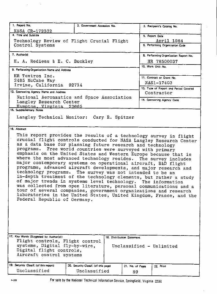
I f1. ReDol't No. 2. Government Accession No. 3. Recipient's Catalog No.
NASA CR-1723324. Title and Subtitle 5. Report Date
I Technology Review of Flight Crucial Flight April 1984nt
Control Systeros s.PerformingorganizationCode
7. Author(s| 8. PerformingOrganization Report No.H, A. Rediess _ E. C. Buckley HR 7850003710. Work Unit No.
I g. PerformingOrganization Name and AddressHR Textron Inc. 11. Contract or Grant No.
2485 McCabe Way NASI-17403
13. Type of Report and Period Covered
Irvine California 92714)
12.SponsoringAgencyNameandAddress Contractor
National Aeronautics and Space Association 14. S-ponsoringAgencycodeLangley Research CenterHnmnton. Virginia 23665
15. Supp4er_ntarv Notes -
! •Langley Technical Monitor: Cary R. Spitzer
,i
16. AbstractThis report provides the results of a technology survey in flightcrucial flight controls conducted for NASA Langley Research Center
as a data base for planning future research and technologyprograms. Free world countries were surveyed with primaryemphasis on the United States and Western Europe because that is
where the most advanced technology resides. The survey includesmajor contemporary systems on operational aircraft, R&D flightprograms, advanced aircraft developments, and major research andtechnology programs. The survey was not intended to be an
in-depthtreatmentof the technologyelements,but rather a studyof major trends in systems level technology. The informationwas collected from open literature, personal communications and a
tour of several companies, government organizations and researchlaboratories in the United States, United Kingdom, France, and theFederal Republic of Germany.
!IJ '17. Key Wor_ (Sug_t_' by Author(s)) 18. Distribution StatementFlight controls,Flight control
systems, Digital fly-by-wire, Unclassified - Unlimited
Digital flight controls,Aircraft control systems
19. Secutiw Qauif; (of this repot) 20. Security Cla=if. (of this _1 21. No. of Pa_ 2Z Rice'Unclassified Unclassified 89
_.zos ForsalebytheNationalTechnicalInformationService.Sprinsfield.Virginia22161

IIIIIIIIIIIIIIIIIII


Related Documents