SAAMI Z299.3 – 2015
Voluntary Industry Performance Standards
for Pressure and Velocity of Centerfire Pistol and Revolver Ammunition
for the Use of Commercial Manufacturers
Sporting Arms and Ammunition Manufacturers’ Institute, Inc.
11 Mile Hill Road, Newtown, Connecticut 06470-2359
Am
eri
ca
n N
ati
on
al S
tan
dard
SAAMI Z299.3 – 2015
Voluntary Industry Performance Standards
for Pressure and Velocity of Centerfire Pistol and Revolver Ammunition
for the Use of Commercial Manufacturers Sponsor
Sporting Arms and Ammunition Manufacturers’ Institute, Inc.
Members
Beretta USA Corporation Broadsword Group LLC Browning Arms Company CCI/Speer Ammunition Colt’s Manufacturing Company LLC COR-BON/Glaser LLC Federal Cartridge Company Fiocchi of America, Inc. Glock Hodgdon Powder Company Hornady Manufacturing Company Kahr Arms
Marlin Firearms Company North American Arms, Inc. O.F. Mossberg & Sons, Inc. Olin Corporation/Winchester Division Remington Arms Company, LLC SIG SAUER, Inc. Smith & Wesson Holding Corp. St. Marks Powder, Inc. Sturm, Ruger & Co., Inc. Taurus Holdings, Inc. Weatherby, Inc.
Associate Members:
Alliant Powder Nosler, Inc Ruag Ammotech USA, Inc. Savage Arms, Inc.
Supporting Members:
Advanced Tactical Armament Concepts, LLC Barnes Bullets, LLC Black Hills Ammunition, Inc. Doubletap Ammunition, Inc. Kent Cartridge, America Knight Rifles LCT Pro Shop One Shot, Inc. ProGrade Ammo Group LLC Southern Ballistic Research, LLC d/b/a SBR
Approved December 14, 2015

Abstract In the interests of safety and interchangeability, this Standard provides pressure and velocity
performance and dimensional characteristics for centerfire pistol and revolver sporting ammunition. Included are procedures and equipment for determining these criteria.
American National Standard
Approval of an American National Standard requires verification by ANSI that the requirements for due process, consensus, and other criteria for approval have been met by the standards developer.
Consensus is established when, in the judgment of the ANSI Board of Standards Review, substantial agreement has been reached by directly and materially affected interests. Substantial agreement means much more than a simple majority, but not necessarily unanimity. Consensus requires that all views and objections be considered, and that a concerted effort be made toward their resolution.
The use of American National Standards is completely voluntary; their existence does not in any respect preclude anyone, whether he has approved the standards or not, from manufacturing, marketing, purchasing, or using products, processes, or procedures not conforming to the standards.
The American National Standards Institute does not develop standards and will in no circumstances give an interpretation of any American National Standard. Moreover, no person shall have the right or authority to issue an interpretation of an American National Standard in the name of the American National Standards Institute. Requests for interpretation should be addressed to the secretariat or sponsor whose name appears on the title page of this standard.
CAUTION NOTICE: This American National Standard may be revised or withdrawn at any time. The procedures of the American National Standards Institute require that action be taken to reaffirm, revise, or withdraw this standard no later than five years from the date of approval. Purchasers of American National Standards may receive current information of all standards by calling or writing the American National Standards Institute.
Published by
Sporting Arms and Ammunition Manufacturers’ Institute, Inc. Flintlock Ridge Office Center 11 Mile Hill Road, Newtown, Connecticut 06470-2359
Copyright © 2015 by Sporting Arms and Ammunition Manufacturers’ Institute, Inc. All rights Reserved.
No part of this publication may be reproduced in any form, in an electronic retrieval system or otherwise, without the prior written permission of the publisher.
Printed in the United States of America
Foreword
The development of this voluntary industry performance standard was initiated under the auspices of the Sporting Arms and Ammunition Manufacturers’ Institute, Inc. (SAAMI). A Products Standards Task Force was established by the Institute in 1975 and charged with the drafting of this and other standards with their subsequent periodic revisions.
The material presented provides the commercial manufacturer of factory-loaded ammunition with pressure and velocity performance and dimensional characteristics. Included are procedures and equipment for determining these criteria. For the purpose of this standard a commercial manufacturer is defined as one who produces ammunition by fabricating component parts from raw materials as opposed to remanufacture with parts originally made by others.
This standard for Centerfire Pistol and Revolver Sporting Ammunition was first published in 1979 and periodically updated until this revision in 2015. Changes in the standard with each revision include minor adjustments of velocities, the addition of new load offerings, and updating of recommended equipment sources and the latest procedures for reporting reference ammunition assessments.
Suggestions for improvement of this standard will be welcome. They should be sent to: The Sporting Arms and Ammunition Manufacturers’ Institute, Inc., Flintlock Ridge Office Center, 11 Mile Hill Road, Newtown, Connecticut 06470-2359.
Consensus for this standard was achieved by use of the Canvass Method.
The following individuals and organizations recognized as having an interest in the standardization of safety requirements for factory-loaded sporting ammunition were contacted prior to the approval of this standard. Inclusion in this list does not necessarily imply that the individual or organization concurred with the submittal of the standard to ANSI:
Aberdeen Proving Grounds – P. Donahue Association of Firearm and Toolmark Examiners – L. Haag Association of Firearm and Toolmark Examiners – J. Hamby, M.A. Boone Ballistics, LLC – B. Boone BPI Outdoors/Bergara Barrel and Custom Rifle Division – M. Hendricks Bureau of Alcohol, Tobacco, Firearms and Explosives – E. Griffith Department of Homeland Security; National Armory – L. Johnson Federal Bureau of Investigation – A. S. Patterson Federal Law Enforcement Training Center (FLETC) – C. Nester, Jr Forensic Ammunition Service – G. Kass H.P. White Laboratory – W. Mason H-S Precision, Inc – T. Houghton Independent Author, Editor and Firearms Manufacturer - R. Cofield Independent Expert – K. Kees Manson Precision Reamers; Division of Loon Lake Precision – D. Manson Massachusetts Institute of Firearms Technology – C. Hildebrandt National Institute of Standards & Technology – K. Rice Natural Resources – Canada – R. Bowes PCB Piezotronics – R. Metz Royal Canadian Mounted Police – R. Poaps Western Powders – D. Luhr
(This foreword is not part of the American National Standard Z299.3)
CENTERFIRE PISTOL & REVOLVER TABLE OF CONTENTS
SAAMI VOLUNTARY PERFORMANCE STANDARDS
i
TABLE OF CONTENTS
SECTION I – CHARACTERISTICS PAGE
Cartridges and Chambers
Full and Abbreviated Names ......................................................................................1
Velocity & Pressure
Velocity Data Interpretation .......................................................................................3
Factors Affecting Pressure Measurements..................................................................4
Explanation of Pressure Terminology ........................................................................6
Explanation of Pressure Measuring Systems ..............................................................8
Velocity & Pressure Data – Crusher ...........................................................................9
Velocity & Pressure Data – Transducer ....................................................................17
Bullet Type Abbreviations ........................................................................................25
Primer
Primers and Primer Pockets ......................................................................................26
Cartridge and Chamber Drawings
9mm Luger ................................................................................................................27
9mm Luger +P ..........................................................................................................27
9x18 Makarov ...........................................................................................................28
9x23 Winchester .......................................................................................................29
10mm Automatic ......................................................................................................30
221 Remington Fireball ............................................................................................31
25 Automatic .............................................................................................................32
25 North American Arms..........................................................................................33
30 Luger (7.65mm) ...................................................................................................34
32 Automatic .............................................................................................................35
32 H&R Magnum .....................................................................................................36
32 North American Arms..........................................................................................37
32 Short Colt .............................................................................................................38
32 Smith & Wesson ..................................................................................................39
32 Smith & Wesson Long .........................................................................................40
32 Smith & Wesson Long Wadcutter .......................................................................41
327 Federal Magnum ................................................................................................42
356 TSW ...................................................................................................................43
357 Magnum .............................................................................................................44
357 Sig ......................................................................................................................45
38 Automatic .............................................................................................................49
38 Smith & Wesson ..................................................................................................46
38 Special ..................................................................................................................47
38 Special Match.......................................................................................................48
38 Special +P ............................................................................................................47
38 Super Automatic +P .............................................................................................49
380 Automatic ...........................................................................................................50
40 Smith & Wesson ..................................................................................................51
400 Cor-Bon..............................................................................................................52
41 Remington Magnum ............................................................................................53
44 Remington Magnum ............................................................................................54
44 S&W Special ........................................................................................................55
CENTERFIRE PISTOL & REVOLVER TABLE OF CONTENTS
SAAMI VOLUNTARY PERFORMANCE STANDARDS
ii
45 Automatic .............................................................................................................56
45 Automatic Match .................................................................................................57
45 Automatic +P .......................................................................................................56
45 Auto Rim ..............................................................................................................58
45 Colt .......................................................................................................................59
45 Glock Automatic Pistol ........................................................................................60
45 Winchester Magnum ............................................................................................61
454 Casull .................................................................................................................62
460 S&W Magnum ...................................................................................................63
475 Linebaugh ..........................................................................................................64
480 Ruger ..................................................................................................................65
50 Action Express .....................................................................................................66
500 S&W Magnum ...................................................................................................67
500 Special ................................................................................................................68
Miscellaneous
Frangibility ................................................................................................................69
Dummy Cartridge – Gun Functioning ......................................................................70
Dummy Cartridge – Display .....................................................................................71
Blank Cartridge .........................................................................................................72
Tolerance – Bullet Weight ........................................................................................73
SECTION II - PROCEDURES
Velocity and Pressure
Procedure: Velocity & Pressure Testing ..................................................................74
Velocity & Pressure Barrels: Qualification .............................................................80
Velocity & Pressure Barrels: Mounting in Receivers ..............................................81
Procedure: Use of Piston Hole Gauges ....................................................................82
Procedure: Piezoelectric Transducer Calibration.....................................................83
Transducer Calibration: Increments and Ranges .....................................................86
Transducer Calibration: Equipment Interconnection ...............................................88
Transducer Calibration: Least Square Line Computation .......................................89
Firing Test: Equipment Interconnection ..................................................................91
Reference Ammunition
Use ............................................................................................................................93
Secondary Reference Ammunition ...........................................................................95
New Lots ...................................................................................................................96
Identification Protocol ..............................................................................................99
Periodic Assessment ...............................................................................................100
Miscellaneous
Frangibility Testing .................................................................................................104
SECTION III – EQUIPMENT
Equipment: Velocity & Copper Crusher Pressure Testing .............................................105
Equipment: Velocity & Conformal Piezoelectric Pressure Testing ...............................107
Copper Crushers
Usage of Crusher Cylinders in Pressure Testing ....................................................109
CENTERFIRE PISTOL & REVOLVER TABLE OF CONTENTS
SAAMI VOLUNTARY PERFORMANCE STANDARDS
iii
Sample Tarage Table ..............................................................................................110
Crusher Cylinders: Dimensions .............................................................................111
Gas Checks
Equipment: 0.146” and 0.206” Gas Checks ...........................................................113
Equipment: Gas Check Tools – Seating and Knockout .........................................114
Equipment: Gas Check Wax ..................................................................................115
Pistons & Piston Holes
Equipment: Pistons and Piston Holes ....................................................................116
Equipment: Piston Hole Gauges ............................................................................119
Piston Oil – Piston and Gas Check .........................................................................121
Headspace Gauges
Headspace Gauges ..................................................................................................122
Reference Ammunition
Equipment: Reference Ammunition Supply ..........................................................127
Equipment: Reference Ammunition Order Procedure ...........................................128
Miscellaneous
Equipment: Frangibility Testing ............................................................................129
Supplier Contact Information .................................................................................130
Equipment: Schematic Layout of Velocity Screens ..............................................131
Equipment: Universal Receiver Collar and Test Barrel ........................................132
Universal Receiver Test Barrel: Installation of Pressure Transducers ..................134
Equipment: Transducer Calibration Fixture Plug with O-ring Seal ......................136
Transducer Location Criteria ..................................................................................137
Equipment: Vented Test Barrel – General .............................................................138
Standard V&P Test Barrels - General
Procedures for Dimensioning Chambers ................................................................139
Procedures for Measuring Barrel Length ................................................................140
Standard Velocity and Pressure Test Barrels
9mm Luger ..............................................................................................................141
9mm Luger +P ........................................................................................................141
9x18 Makarov .........................................................................................................142
9x23 Winchester .....................................................................................................143
10mm Automatic ....................................................................................................144
221 Remington Fireball ..........................................................................................145
25 Automatic ...........................................................................................................146
25 North American Arms........................................................................................147
30 Luger (7.65mm) .................................................................................................148
32 Automatic ...........................................................................................................149
32 H&R Magnum ...................................................................................................150
32 North American Arms........................................................................................151
32 Short Colt ...........................................................................................................152
32 Smith & Wesson ................................................................................................153
32 Smith & Wesson Long .......................................................................................154
32 Smith & Wesson Long Wadcutter .....................................................................154
327 Federal Magnum ..............................................................................................155
356 TSW .................................................................................................................156
357 Magnum ...........................................................................................................157
357 Sig ....................................................................................................................158
38 Automatic ...........................................................................................................159
CENTERFIRE PISTOL & REVOLVER TABLE OF CONTENTS
SAAMI VOLUNTARY PERFORMANCE STANDARDS
iv
38 Smith & Wesson ................................................................................................160
38 Special ................................................................................................................161
38 Special Match.....................................................................................................161
38 Special +P ..........................................................................................................161
38 Super Automatic +P ...........................................................................................159
380 Automatic .........................................................................................................162
40 Smith & Wesson ................................................................................................163
400 Cor-Bon............................................................................................................164
41 Remington Magnum ..........................................................................................165
44 Remington Magnum ..........................................................................................166
44 S&W Special ......................................................................................................167
45 Automatic ...........................................................................................................168
45 Automatic Match ...............................................................................................168
45 Automatic +P .....................................................................................................168
45 Auto Rim ............................................................................................................169
45 Colt .....................................................................................................................170
45 Glock Automatic Pistol ......................................................................................171
45 Winchester Magnum ..........................................................................................172
454 Casull ...............................................................................................................173
460 S&W Magnum .................................................................................................174
475 Linebaugh ........................................................................................................175
480 Ruger ................................................................................................................176
50 Action Express ...................................................................................................177
500 S&W Magnum .................................................................................................178
500 Special ..............................................................................................................179
SECTION IV – DEFINITIVE PROOF LOADS
Definition and Purpose ....................................................................................................180
Proof Pressure Data Interpretation ...................................................................................181
Proof Pressure Data – Crusher .........................................................................................183
Proof Pressure Data – Transducer ....................................................................................185
Proof Load Supply ...........................................................................................................187
Proof Cartridge Identification ..........................................................................................188
Definitive Proof Package Identification...........................................................................189
SECTION I – CHARACTERISTICS CENTERFIRE PISTOL & REVOLVER
CARTRIDGES AND CHAMBERS FULL AND ABBREVIATED NAMES
SAAMI VOLUNTARY PERFORMANCE STANDARDS
1
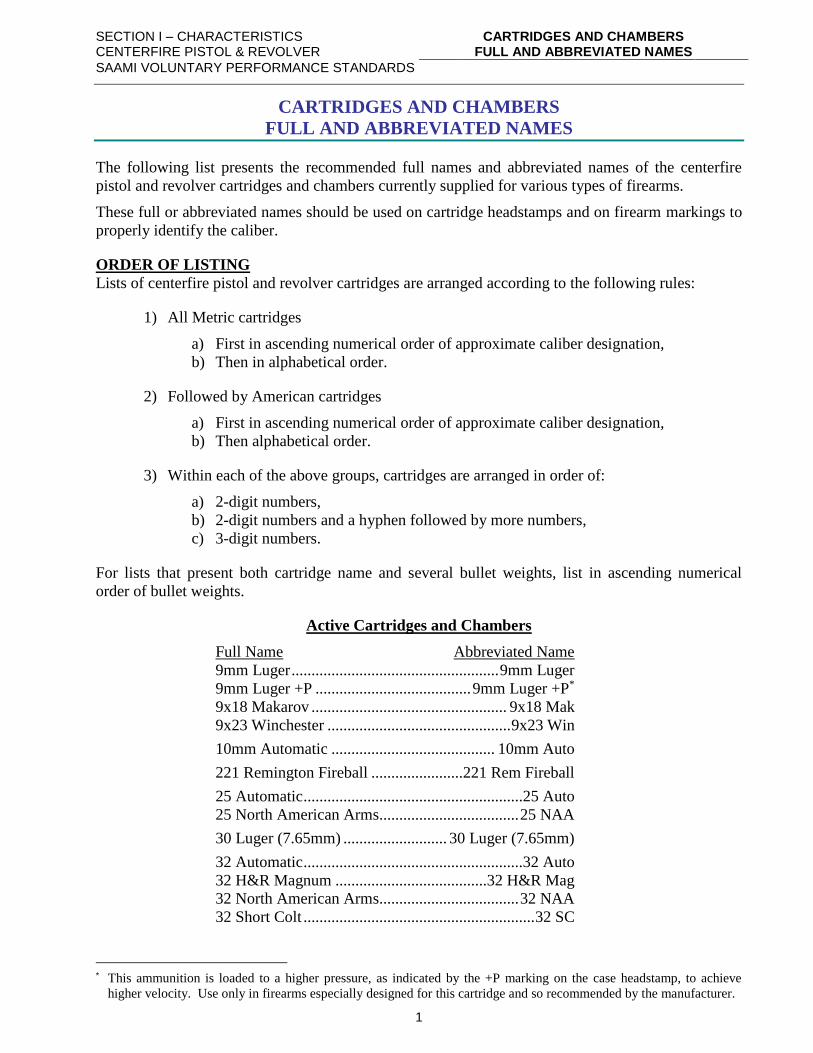
CARTRIDGES AND CHAMBERS
FULL AND ABBREVIATED NAMES
The following list presents the recommended full names and abbreviated names of the centerfire
pistol and revolver cartridges and chambers currently supplied for various types of firearms.
These full or abbreviated names should be used on cartridge headstamps and on firearm markings to
properly identify the caliber.
ORDER OF LISTING
Lists of centerfire pistol and revolver cartridges are arranged according to the following rules:
1) All Metric cartridges
a) First in ascending numerical order of approximate caliber designation,
b) Then in alphabetical order.
2) Followed by American cartridges
a) First in ascending numerical order of approximate caliber designation,
b) Then alphabetical order.
3) Within each of the above groups, cartridges are arranged in order of:
a) 2-digit numbers,
b) 2-digit numbers and a hyphen followed by more numbers,
c) 3-digit numbers.
For lists that present both cartridge name and several bullet weights, list in ascending numerical
order of bullet weights.
Active Cartridges and Chambers
Full Name Abbreviated Name
9mm Luger .................................................... 9mm Luger
9mm Luger +P ....................................... 9mm Luger +P*
9x18 Makarov ................................................. 9x18 Mak
9x23 Winchester .............................................. 9x23 Win
10mm Automatic ......................................... 10mm Auto
221 Remington Fireball .......................221 Rem Fireball
25 Automatic .......................................................25 Auto
25 North American Arms................................... 25 NAA
30 Luger (7.65mm) .......................... 30 Luger (7.65mm)
32 Automatic .......................................................32 Auto
32 H&R Magnum ......................................32 H&R Mag
32 North American Arms................................... 32 NAA
32 Short Colt .......................................................... 32 SC
* This ammunition is loaded to a higher pressure, as indicated by the +P marking on the case headstamp, to achieve
higher velocity. Use only in firearms especially designed for this cartridge and so recommended by the manufacturer.
SECTION I – CHARACTERISTICS CENTERFIRE PISTOL & REVOLVER
CARTRIDGES AND CHAMBERS FULL AND ABBREVIATED NAMES
SAAMI VOLUNTARY PERFORMANCE STANDARDS
2
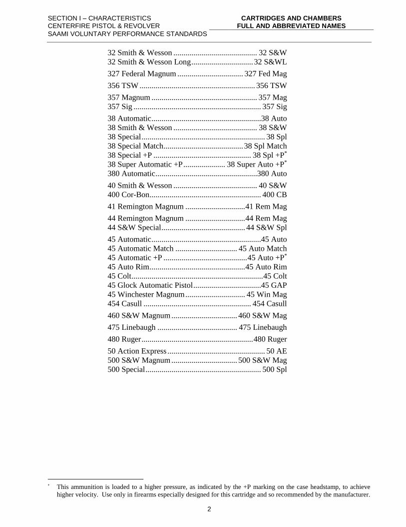
32 Smith & Wesson .......................................... 32 S&W
32 Smith & Wesson Long ............................... 32 S&WL
327 Federal Magnum ................................. 327 Fed Mag
356 TSW .......................................................... 356 TSW
357 Magnum ..................................................... 357 Mag
357 Sig ................................................................ 357 Sig
38 Automatic .......................................................38 Auto
38 Smith & Wesson .......................................... 38 S&W
38 Special .............................................................. 38 Spl
38 Special Match........................................ 38 Spl Match
38 Special +P ................................................. 38 Spl +P*
38 Super Automatic +P ..................... 38 Super Auto +P*
380 Automatic ...................................................380 Auto
40 Smith & Wesson .......................................... 40 S&W
400 Cor-Bon........................................................ 400 CB
41 Remington Magnum .............................. 41 Rem Mag
44 Remington Magnum .............................. 44 Rem Mag
44 S&W Special .......................................... 44 S&W Spl
45 Automatic .......................................................45 Auto
45 Automatic Match ............................... 45 Auto Match
45 Automatic +P .......................................... 45 Auto +P*
45 Auto Rim ................................................ 45 Auto Rim
45 Colt .................................................................. 45 Colt
45 Glock Automatic Pistol ..................................45 GAP
45 Winchester Magnum .............................. 45 Win Mag
454 Casull ...................................................... 454 Casull
460 S&W Magnum ................................. 460 S&W Mag
475 Linebaugh ........................................ 475 Linebaugh
480 Ruger ........................................................ 480 Ruger
50 Action Express ................................................. 50 AE
500 S&W Magnum ................................. 500 S&W Mag
500 Special .......................................................... 500 Spl
* This ammunition is loaded to a higher pressure, as indicated by the +P marking on the case headstamp, to achieve
higher velocity. Use only in firearms especially designed for this cartridge and so recommended by the manufacturer.
SECTION I – CHARACTERISTICS CENTERFIRE PISTOL & REVOLVER
VELOCITY DATA INTERPRETATION
SAAMI VOLUNTARY PERFORMANCE STANDARDS
3
VELOCITY DATA INTERPRETATION
Velocity recommendations are stated on the basis of a nominal lot mean velocity as measured using
equipment in accordance with the requirements of Section III and the procedures detailed in Section
II. Due to the fact that sporting firearms for general distribution are typically manufactured to
dimensional tolerances greater than those specified for test barrels, there should be no expectation
that these velocities can be duplicated from any test utilizing firearms. This situation is further
confounded by discrepancies in barrel length. Furthermore, once ammunition has left the control of
the manufacturer, storage conditions outside those recommended by the manufacturer may cause
variations in the velocity as measured using test equipment and procedures which conform to the
requirements of this Standard.
The values presented on pages 9 through 24 are recommended values for the use of ammunition
producers at the time of manufacture. It is the responsibility of the manufacturer to establish sample
sizes, sampling frequencies, and tolerances to ensure the performance of the ammunition obtained by
the ultimate user meets all applicable safety and functional standards. Of particular importance in
establishing velocity tolerances is the understanding that velocities significantly higher than the
nominal lot mean can cause actual maximum range performance to exceed expected values.
Ammunition tested subsequent to manufacture using equipment and procedures conforming to these
guidelines can be expected to produce velocities within a tolerance of ±90 fps of the tabulated
values.
SECTION I – CHARACTERISTICS CENTERFIRE PISTOL & REVOLVER
FACTORS AFFECTING PRESSURE MEASUREMENTS
SAAMI VOLUNTARY PERFORMANCE STANDARDS
4
FACTORS AFFECTING PRESSURE MEASUREMENTS
Two principal methods of measuring centerfire pistol and revolver pressures are recognized: the
copper crusher method and the piezoelectric transducer method. One or the other may be used or
they may be used simultaneously.
There are three principal factors affecting pressure measurements. These are instrumentation,
ammunition and procedure. The following lists present the items in each category that may cause
difficulties in testing carried out with the two methods.
I. FACTORS IN COPPER CRUSHER TESTING
INSTRUMENTATION
1. Condition of test barrel (whether minimum or maximum bore, chamber size and headspace,
amount of erosion at throat and bore).
2. Diameter of piston and piston hole.
3. Fit of piston in piston hole.
4. Location of piston hole.
5. Tightness of barrel mounting in Universal Receiver, if used.
6. Shape, size and protrusion of firing pin beyond breech face.
7. Force of firing pin blow.
8. Size, material and characteristics of the pressure-sensitive element of the gauge (copper crusher
cylinders).
9. Type, size and condition of gas check.
10. Type of piston and gas check lubricant.
11. Quality and tolerance of piston hole gauges and headspace gauges.
12. Quality of crusher measuring instrument.
AMMUNITION
1. Condition of cartridge.
2. Position of powder in cartridge case.
3. Temperature of ammunition.
PROCEDURE
1. Failure to mount pressure barrel properly in Universal Receiver or other test action to assure
minimum headspace.
2. Failure to rotate cartridge and close breech carefully to assure proper powder positioning.
3. Failure to wipe piston ends, crusher and setscrew face to remove excess oil.
4. Failure to center crusher cylinder on piston and properly adjust setscrew.
5. Failure to fire warming shots.
6. Overheating barrel by excessive rate of fire.
7. Failure to clean bore and control metal fouling.
8. Failure to clear barrel of brass disk blanked from the case wall and gas check from previous
shot.
SECTION I – CHARACTERISTICS CENTERFIRE PISTOL & REVOLVER
FACTORS AFFECTING PRESSURE MEASUREMENTS
SAAMI VOLUNTARY PERFORMANCE STANDARDS
5
II. FACTORS IN PIEZOELECTRIC TRANSDUCER TESTING
INSTRUMENTATION
1. Condition of test barrel (whether minimum or maximum bore, chamber size and headspace,
amount of erosion at throat and bore).
2. Fit of transducer in barrel.
3. Location of transducer.
4. Tightness of barrel mounting in Universal Receiver, if used.
5. Shape, size and protrusion of firing pin beyond breech face.
6. Force of firing pin blow.
7. Characteristics of the transducer.
8. Quality of the transducer.
9. Quality of the read-out system.
AMMUNITION
1. Condition of cartridge.
2. Position of powder in cartridge case.
3. Temperature of ammunition.
PROCEDURE
1. Failure to mount pressure barrel properly in Universal Receiver or other test action to assure
minimum headspace.
2. Failure to rotate cartridge and close breech carefully to assure proper powder positioning.
3. Failure to fire warming shots.
4. Overheating barrel by excessive rate of fire.
5. Failure to clean bore and control metal fouling.
6. Failure to protect transducer against contamination, such as oil or water.
7. Transducer calibration.
8. Read-out system calibration.
SECTION I – CHARACTERISTICS CENTERFIRE PISTOL & REVOLVER
EXPLANATION OF PRESSURE TERMINOLOGY
SAAMI VOLUNTARY PERFORMANCE STANDARDS
6
EXPLANATION OF PRESSURE TERMINOLOGY
The SAAMI Pressure data outlined in this section is based on a Maximum Average Pressure for each
cartridge and a Coefficient of Variation of 5%. The Coefficient of Variation (CV) of 5% was based
on the CV that exists for the 40,000 psi pressure level and is calculated by dividing the population
standard deviation ( = 2,000 psi) by the Maximum Average Pressure (MAP = 40,000 psi) which
equals 0.05 (5%). All other pressure terminology is derived directly from these two terms.
SAAMI recognizes two pressure-measuring systems. The preferred system is the piezoelectric
transducer system with the transducer flush-mounted in the chamber of the test barrel. Pressure
developed by the burning propellant exerts force on the transducer through the cartridge case wall
causing the transducer to deflect, creating a measurable electric charge. Pressures measured with
this system are expressed in units of "pounds per square inch" (abbreviated psi).
The second, older system employs a copper crusher cylinder which is compressed by a piston fitted
to a piston hole into the chamber of the test barrel. Pressure generated by the burning propellant acts
on the base of the piston forcing the piston to move, thereby permanently compressing the copper
cylinder. Pressures measured by this system are expressed in "Copper Units of Pressure"
(abbreviated as "CUP").
Throughout the following text the pressure is expressed in terms of "pounds per square inch" ("psi")
however, it should be understood that the same procedures apply to pressures expressed in "Copper
Units of Pressure" (CUP).
Maximum Average Pressure - is the recommended maximum pressure level for loading commercial
sporting ammunition.
Standard Deviation () - The Standard Deviation for each Maximum Average Pressure level is based
on a Coefficient of Variation of 5%. This 5% Coefficient of Variation is maintained throughout the
SAAMI pressure spectrum providing a realistic Standard Deviation for each pressure level. To
obtain the Standard Deviation for a particular MAP, multiply the MAP by 0.05 (i.e., 40,000 psi x
0.05 = 2,000 psi).
Standard Error ( )xσ - The standard error is calculated by dividing the Standard Deviation
(population S. D. = ) by the square root of the sample size nσσx
=
Maximum Probable Lot Mean (MPLM) - The MPLM is calculated by adding two standard errors to
the Maximum Average Pressure in order to assure there is a 97.5% probability that the Maximum
Probable Lot Mean pressure is not exceeded. See Figure 1.
The SAAMI pressures are calculated based on a sample size of ten (10). The Maximum Probable
Lot Mean represents the midpoint of the upper service pressure distribution. See Figure 1. For
example, if the Maximum Average Pressure is 40,000 psi, the Maximum Probable Lot Mean
(MPLM) is calculated as follows:
MPLM = Maximum Average Pressure + 2 standard errors
MPLM = 40,000 psi + [(40,000 psi x 0.05)/√10] x 2
MPLM = 40,000 psi + (633 psi x 2) = 40,000 + 1266 psi = 41,266 psi rounded
to 41,300 psi
SECTION I – CHARACTERISTICS CENTERFIRE PISTOL & REVOLVER
EXPLANATION OF PRESSURE TERMINOLOGY
SAAMI VOLUNTARY PERFORMANCE STANDARDS
7
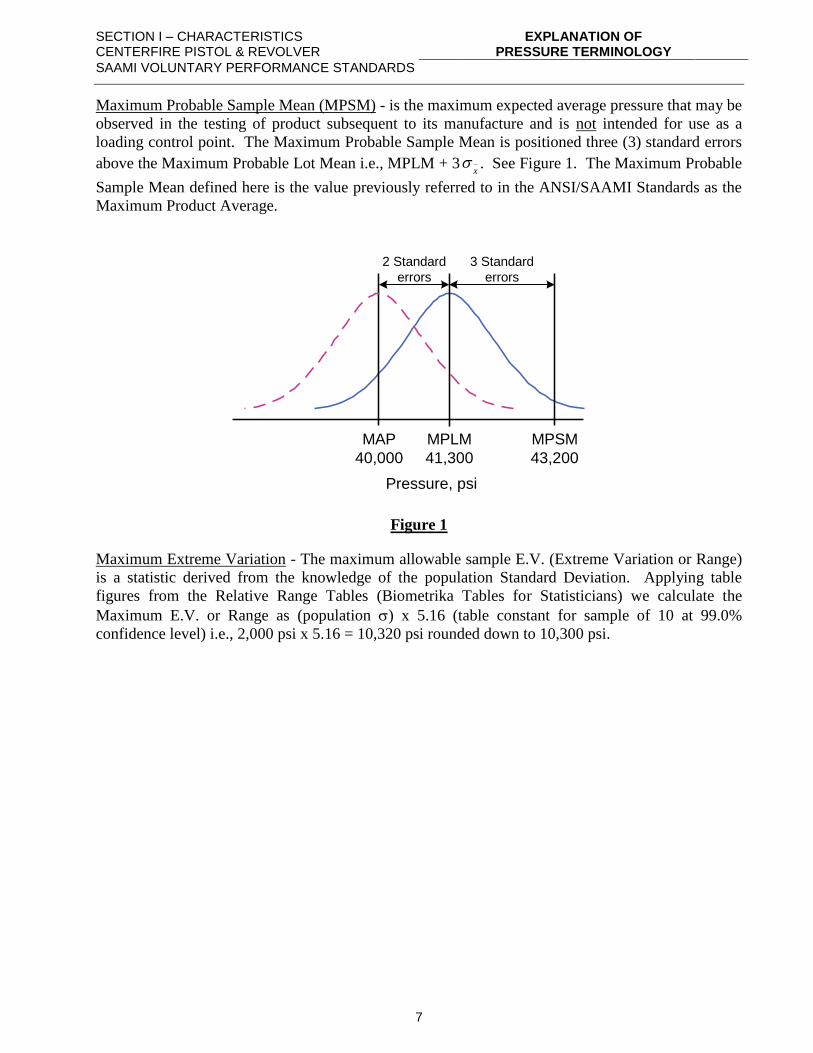
Maximum Probable Sample Mean (MPSM) - is the maximum expected average pressure that may be
observed in the testing of product subsequent to its manufacture and is not intended for use as a
loading control point. The Maximum Probable Sample Mean is positioned three (3) standard errors
above the Maximum Probable Lot Mean i.e., MPLM + 3x
. See Figure 1. The Maximum Probable
Sample Mean defined here is the value previously referred to in the ANSI/SAAMI Standards as the
Maximum Product Average.
MAP
40,000
Pressure, psi
MPLM
41,300
MPSM
43,200
2 Standard
errors
3 Standard
errors
Figure 1
Maximum Extreme Variation - The maximum allowable sample E.V. (Extreme Variation or Range)
is a statistic derived from the knowledge of the population Standard Deviation. Applying table
figures from the Relative Range Tables (Biometrika Tables for Statisticians) we calculate the
Maximum E.V. or Range as (population ) x 5.16 (table constant for sample of 10 at 99.0%
confidence level) i.e., 2,000 psi x 5.16 = 10,320 psi rounded down to 10,300 psi.
SECTION I – CHARACTERISTICS CENTERFIRE PISTOL & REVOLVER
EXPLANATION OF PRESSURE MEASURING SYSTEMS
SAAMI VOLUNTARY PERFORMANCE STANDARDS
8
EXPLANATION OF PRESSURE MEASURING SYSTEMS
The two SAAMI recognized pressure-measuring systems for centerfire pistol and revolver cartridges
are the copper crusher system and the piezoelectric transducer system.
A brief explanation of these two systems follows:
COPPER CRUSHER SYSTEM
This system employs a copper crusher cylinder that is compressed by a piston fitted to a piston hole
into the chamber of the test barrel. The pressure developed by the gases from the burning propellant
acts through the piston hole, allowing the gases to force the piston upward, and thereby permanently
compressing the copper crusher cylinder. The Sporting Arms and Ammunition Manufacturers'
Institute has adopted the pressure units designation of "Copper Units of Pressure" (abbreviated CUP)
for this system. This designation applies only to values obtained using the particular crushers, tarage
tables and methods outlined in this Standard.
PIEZOELECTRIC TRANSDUCER SYSTEM
This system employs a piezoelectric transducer flush mounted in the chamber of the test barrel.
Pressure developed by the gases from the burning propellant exerts force on the transducer through
the cartridge case wall causing the transducer to deflect, creating a measurable electric charge. This
electrical charge is converted into a reading of pressure.
The Sporting Arms and Ammunition Manufacturers' Institute has adopted the pressure units
designation of "pounds per square inch" (abbreviated psi) for this system. This designation applies
to values obtained with transducers and methods as outlined in this Standard.
SECTION I – CHARACTERISTICS CENTERFIRE PISTOL & REVOLVER
CENTERFIRE PISTOL & REVOLVER VELOCITY AND PRESSURE DATA – CRUSHER
SAAMI VOLUNTARY PERFORMANCE STANDARDS
9
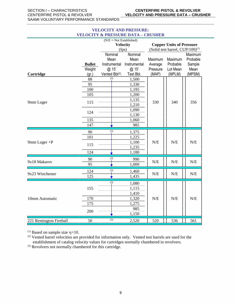
VELOCITY AND PRESSURE:
VELOCITY & PRESSURE DATA – CRUSHER
(N/E = Not Established)
Velocity Copper Units of Pressure
(fps) (Solid test barrel, CUP/100)(1)
Nominal Nominal Maximum Mean Mean Maximum Maximum Probable Bullet Instrumental Instrumental Average Probable Sample
Weight @ 15’ @ 15’ Pressure Lot Mean Mean Cartridge (gr.) Vented Bbl(2). Test Bbl. (MAP) (MPLM) (MPSM)
9mm Luger
88 (3) 1,500
330
340
356
95 1,330
100 1,195
105 1,200
115
1,135
1,210
124
1,090
1,130
135 1,060
147 985
9mm Luger +P
90 (3) 1,375
N/E
N/E
N/E
101 1,225
115
1,100
1,235
124 1,180
9x18 Makarov 90 (3) 990
N/E
N/E
N/E 95 1,000
9x23 Winchester 124 (3) 1,460
N/E
N/E
N/E 125 1,435
10mm Automatic
155
(3) 1,080
N/E
N/E
N/E
1,115
1,410
170 1,320
175 1,275
200
985
1,150
221 Remington Fireball 50 (3) 2,520 520 536 561
(1) Based on sample size =10. (2) Vented barrel velocities are provided for information only. Vented test barrels are used for the
establishment of catalog velocity values for cartridges normally chambered in revolvers. (3) Revolvers not normally chambered for this cartridge.
SECTION I – CHARACTERISTICS CENTERFIRE PISTOL & REVOLVER
CENTERFIRE PISTOL & REVOLVER VELOCITY AND PRESSURE DATA – CRUSHER
SAAMI VOLUNTARY PERFORMANCE STANDARDS
10
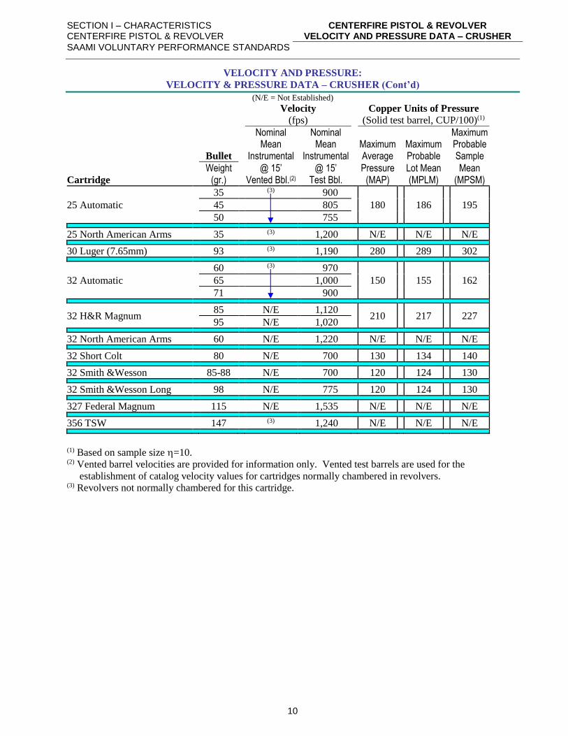
VELOCITY AND PRESSURE:
VELOCITY & PRESSURE DATA – CRUSHER (Cont’d)
(N/E = Not Established)
Velocity Copper Units of Pressure
(fps) (Solid test barrel, CUP/100)(1)
Nominal Nominal Maximum Mean Mean Maximum Maximum Probable Bullet Instrumental Instrumental Average Probable Sample
Weight @ 15’ @ 15’ Pressure Lot Mean Mean Cartridge (gr.) Vented Bbl.(2) Test Bbl. (MAP) (MPLM) (MPSM)
25 Automatic
35 (3) 900
180
186
195 45 805
50 755
25 North American Arms 35 (3) 1,200 N/E N/E N/E
30 Luger (7.65mm) 93 (3) 1,190 280 289 302
32 Automatic
60 (3) 970
150
155
162 65 1,000
71 900
32 H&R Magnum 85 N/E 1,120
210
217
227 95 N/E 1,020
32 North American Arms 60 N/E 1,220 N/E N/E N/E
32 Short Colt 80 N/E 700 130 134 140
32 Smith &Wesson 85-88 N/E 700 120 124 130
32 Smith &Wesson Long 98 N/E 775 120 124 130
327 Federal Magnum 115 N/E 1,535 N/E N/E N/E
356 TSW 147 (3) 1,240 N/E N/E N/E
(1) Based on sample size =10. (2) Vented barrel velocities are provided for information only. Vented test barrels are used for the
establishment of catalog velocity values for cartridges normally chambered in revolvers. (3) Revolvers not normally chambered for this cartridge.
SECTION I – CHARACTERISTICS CENTERFIRE PISTOL & REVOLVER
CENTERFIRE PISTOL & REVOLVER VELOCITY AND PRESSURE DATA – CRUSHER
SAAMI VOLUNTARY PERFORMANCE STANDARDS
11
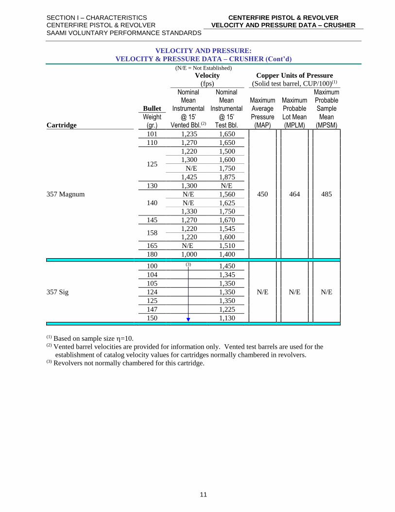
VELOCITY AND PRESSURE:
VELOCITY & PRESSURE DATA – CRUSHER (Cont’d)
(N/E = Not Established)
Velocity Copper Units of Pressure
(fps) (Solid test barrel, CUP/100)(1)
Nominal Nominal Maximum Mean Mean Maximum Maximum Probable Bullet Instrumental Instrumental Average Probable Sample
Weight @ 15’ @ 15’ Pressure Lot Mean Mean Cartridge (gr.) Vented Bbl.(2) Test Bbl. (MAP) (MPLM) (MPSM)
357 Magnum
101 1,235 1,650
450
464
485
110 1,270 1,650
125
1,220 1,500
1,300 1,600
N/E 1,750
1,425 1,875
130 1,300 N/E
140
N/E 1,560
N/E 1,625
1,330 1,750
145 1,270 1,670
158
1,220 1,545
1,220 1,600
165 N/E 1,510
180 1,000 1,400
357 Sig
100 (3) 1,450
N/E
N/E
N/E
104 1,345
105 1,350
124 1,350
125 1,350
147 1,225
150 1,130
(1) Based on sample size =10. (2) Vented barrel velocities are provided for information only. Vented test barrels are used for the
establishment of catalog velocity values for cartridges normally chambered in revolvers. (3) Revolvers not normally chambered for this cartridge.
SECTION I – CHARACTERISTICS CENTERFIRE PISTOL & REVOLVER
CENTERFIRE PISTOL & REVOLVER VELOCITY AND PRESSURE DATA – CRUSHER
SAAMI VOLUNTARY PERFORMANCE STANDARDS
12
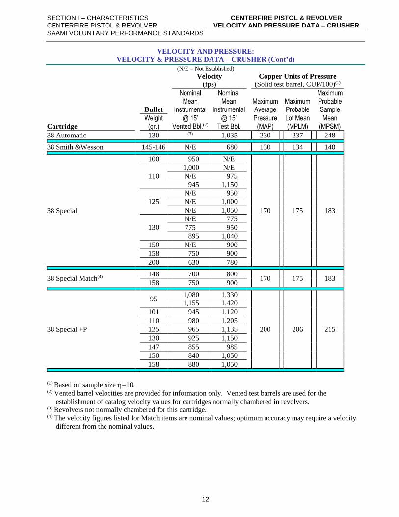
VELOCITY AND PRESSURE:
VELOCITY & PRESSURE DATA – CRUSHER (Cont’d)
(N/E = Not Established)
Velocity Copper Units of Pressure
(fps) (Solid test barrel, CUP/100)(1)
Nominal Nominal Maximum Mean Mean Maximum Maximum Probable Bullet Instrumental Instrumental Average Probable Sample
Weight @ 15’ @ 15’ Pressure Lot Mean Mean Cartridge (gr.) Vented Bbl.(2) Test Bbl. (MAP) (MPLM) (MPSM)
38 Automatic 130 (3) 1,035 230 237 248
38 Smith &Wesson 145-146 N/E 680 130 134 140
38 Special
100 950 N/E
170
175
183
110
1,000 N/E
N/E 975
945 1,150
125
N/E 950
N/E 1,000
N/E 1,050
130
N/E 775
775 950
895 1,040
150 N/E 900
158 750 900
200 630 780
38 Special Match(4) 148 700 800
170
175
183 158 750 900
38 Special +P
95
1,080 1,330
200
206
215
1,155 1,420
101 945 1,120
110 980 1,205
125 965 1,135
130 925 1,150
147 855 985
150 840 1,050
158 880 1,050
(1) Based on sample size =10. (2) Vented barrel velocities are provided for information only. Vented test barrels are used for the
establishment of catalog velocity values for cartridges normally chambered in revolvers. (3) Revolvers not normally chambered for this cartridge. (4) The velocity figures listed for Match items are nominal values; optimum accuracy may require a velocity
different from the nominal values.
SECTION I – CHARACTERISTICS CENTERFIRE PISTOL & REVOLVER
CENTERFIRE PISTOL & REVOLVER VELOCITY AND PRESSURE DATA – CRUSHER
SAAMI VOLUNTARY PERFORMANCE STANDARDS
13
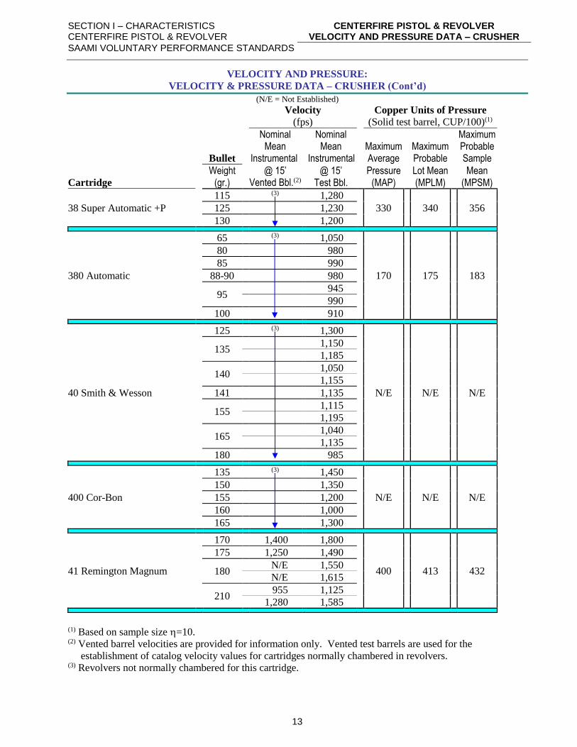
VELOCITY AND PRESSURE:
VELOCITY & PRESSURE DATA – CRUSHER (Cont’d)
(N/E = Not Established)
Velocity Copper Units of Pressure
(fps) (Solid test barrel, CUP/100)(1)
Nominal Nominal Maximum Mean Mean Maximum Maximum Probable Bullet Instrumental Instrumental Average Probable Sample
Weight @ 15’ @ 15’ Pressure Lot Mean Mean Cartridge (gr.) Vented Bbl.(2) Test Bbl. (MAP) (MPLM) (MPSM)
38 Super Automatic +P
115 (3) 1,280
330
340
356 125 1,230
130 1,200
380 Automatic
65 (3) 1,050
170
175
183
80 980
85 990
88-90 980
95
945
990
100 910
40 Smith & Wesson
125 (3) 1,300
N/E
N/E
N/E
135
1,150
1,185
140
1,050
1,155
141 1,135
155
1,115
1,195
165
1,040
1,135
180 985
400 Cor-Bon
135 (3) 1,450
N/E
N/E
N/E
150 1,350
155 1,200
160 1,000
165 1,300
41 Remington Magnum
170 1,400 1,800
400
413
432
175 1,250 1,490
180
N/E 1,550
N/E 1,615
210
955 1,125
1,280 1,585
(1) Based on sample size =10. (2) Vented barrel velocities are provided for information only. Vented test barrels are used for the
establishment of catalog velocity values for cartridges normally chambered in revolvers. (3) Revolvers not normally chambered for this cartridge.

SECTION I – CHARACTERISTICS CENTERFIRE PISTOL & REVOLVER
CENTERFIRE PISTOL & REVOLVER VELOCITY AND PRESSURE DATA – CRUSHER
SAAMI VOLUNTARY PERFORMANCE STANDARDS
14
VELOCITY AND PRESSURE:
VELOCITY & PRESSURE DATA – CRUSHER (Cont’d)
(N/E = Not Established)
Velocity Copper Units of Pressure
(fps) (Solid test barrel, CUP/100)(1)
Nominal Nominal Maximum Mean Mean Maximum Maximum Probable Bullet Instrumental Instrumental Average Probable Sample
Weight @ 15’ @ 15’ Pressure Lot Mean Mean Cartridge (gr.) Vented Bbl.(2) Test Bbl. (MAP) (MPLM) (MPSM)
44 Remington Magnum
180 1,600 1,800
400
413
432
210 1,250 1,425
220 N/E 1,580
225 N/E 1,275
240
995 1,175
1,150 1,500
1,170 1,600
1,335 1,600
250
N/E 1,150
1,150 1,475
N/E 1,520
275 1,185 1,335
300 N/E 1,200
44 S&W Special
200
N/E 900
140
144
151 N/E 1,025
240 750 800
246 N/E 800
(1) Based on sample size =10. (2) Vented barrel velocities are provided for information only. Vented test barrels are used for the
establishment of catalog velocity values for cartridges normally chambered in revolvers.
SECTION I – CHARACTERISTICS CENTERFIRE PISTOL & REVOLVER
CENTERFIRE PISTOL & REVOLVER VELOCITY AND PRESSURE DATA – CRUSHER
SAAMI VOLUNTARY PERFORMANCE STANDARDS
15
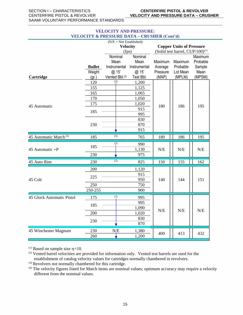
VELOCITY AND PRESSURE:
VELOCITY & PRESSURE DATA – CRUSHER (Cont’d)
(N/E = Not Established)
Velocity Copper Units of Pressure
(fps) (Solid test barrel, CUP/100)(1)
Nominal Nominal Maximum Mean Mean Maximum Maximum Probable Bullet Instrumental Instrumental Average Probable Sample
Weight @ 15’ @ 15’ Pressure Lot Mean Mean Cartridge (gr.) Vented Bbl.(2) Test Bbl. (MAP) (MPLM) (MPSM)
45 Automatic
120 (3) 1,200
180
186
195
155 1,125
165 1,065
170 1,050
175 1,020
185
915
995
230
830
870
915
45 Automatic Match (3) 185 (3) 765 180 186 195
45 Automatic +P
185
(3) 990
N/E
N/E
N/E 1,130
230 975
45 Auto Rim 230 (3) 825 150 155 162
45 Colt
200 1,120
140
144
151
225
915
950
250 750
250-255 900
45 Glock Automatic Pistol 175 (3) 995
N/E
N/E
N/E
185
995
1,090
200 1,020
230
830
870
45 Winchester Magnum 230 N/E 1,380 400
413
432
260 1,200
(1) Based on sample size =10. (2) Vented barrel velocities are provided for information only. Vented test barrels are used for the
establishment of catalog velocity values for cartridges normally chambered in revolvers. (3) Revolvers not normally chambered for this cartridge. (4) The velocity figures listed for Match items are nominal values; optimum accuracy may require a velocity
different from the nominal values.
SECTION I – CHARACTERISTICS CENTERFIRE PISTOL & REVOLVER
CENTERFIRE PISTOL & REVOLVER VELOCITY AND PRESSURE DATA – CRUSHER
SAAMI VOLUNTARY PERFORMANCE STANDARDS
16
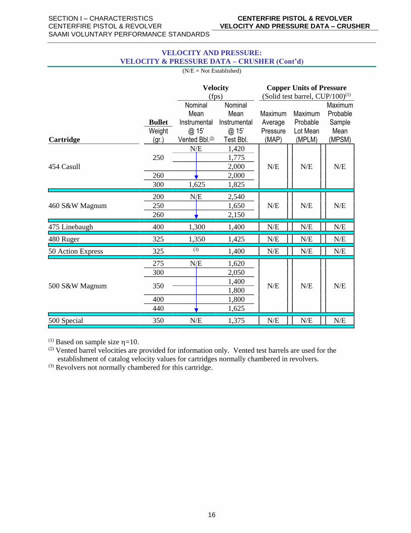
VELOCITY AND PRESSURE:
VELOCITY & PRESSURE DATA – CRUSHER (Cont’d)
(N/E = Not Established)
Velocity Copper Units of Pressure
(fps) (Solid test barrel, CUP/100)(1)
Nominal Nominal Maximum Mean Mean Maximum Maximum Probable Bullet Instrumental Instrumental Average Probable Sample
Weight @ 15’ @ 15’ Pressure Lot Mean Mean Cartridge (gr.) Vented Bbl.(2) Test Bbl. (MAP) (MPLM) (MPSM)
454 Casull
250
N/E 1,420
N/E
N/E
N/E
1,775
2,000
260 2,000
300 1,625 1,825
460 S&W Magnum
200 N/E 2,540
N/E
N/E
N/E 250 1,650
260 2,150
475 Linebaugh 400 1,300 1,400 N/E N/E N/E
480 Ruger 325 1,350 1,425 N/E N/E N/E
50 Action Express 325 (3) 1,400 N/E N/E N/E
500 S&W Magnum
275 N/E 1,620
N/E
N/E
N/E
300 2,050
350
1,400
1,800
400 1,800
440 1,625
500 Special 350 N/E 1,375 N/E N/E N/E
(1) Based on sample size =10. (2) Vented barrel velocities are provided for information only. Vented test barrels are used for the
establishment of catalog velocity values for cartridges normally chambered in revolvers. (3) Revolvers not normally chambered for this cartridge.
SECTION I – CHARACTERISTICS CENTERFIRE PISTOL & REVOLVER
CENTERFIRE PISTOL & REVOLVER VELOCITY & PRESSURE DATA – TRANSDUCER
SAAMI VOLUNTARY PERFORMANCE STANDARDS
17
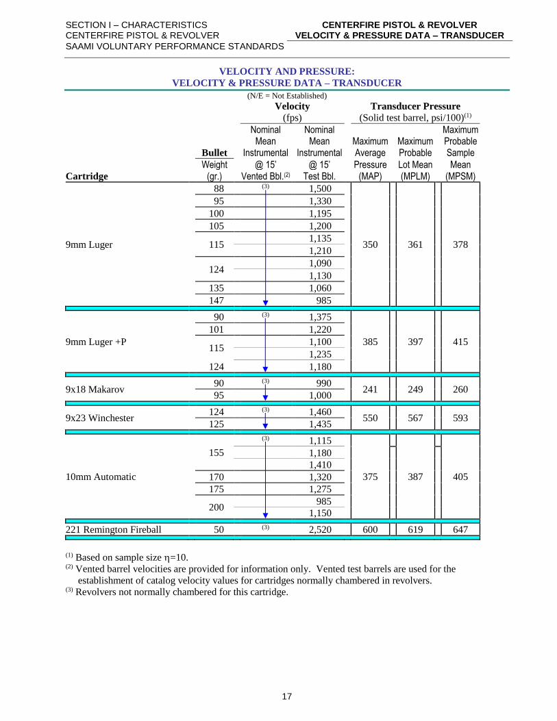
VELOCITY AND PRESSURE:
VELOCITY & PRESSURE DATA – TRANSDUCER
(N/E = Not Established)
Velocity Transducer Pressure
(fps) (Solid test barrel, psi/100)(1)
Nominal Nominal Maximum Mean Mean Maximum Maximum Probable Bullet Instrumental Instrumental Average Probable Sample
Weight @ 15’ @ 15’ Pressure Lot Mean Mean Cartridge (gr.) Vented Bbl.(2) Test Bbl. (MAP) (MPLM) (MPSM)
9mm Luger
88 (3) 1,500
350
361
378
95 1,330
100 1,195
105 1,200
115
1,135
1,210
124
1,090
1,130
135 1,060
147 985
9mm Luger +P
90 (3) 1,375
385
397
415
101 1,220
115
1,100
1,235
124 1,180
9x18 Makarov 90 (3) 990
241
249
260 95 1,000
9x23 Winchester 124 (3) 1,460
550
567
593 125 1,435
10mm Automatic
155
(3) 1,115
375
387
405
1,180
1,410
170 1,320
175 1,275
200
985
1,150
221 Remington Fireball 50 (3) 2,520 600 619 647
(1) Based on sample size =10. (2) Vented barrel velocities are provided for information only. Vented test barrels are used for the
establishment of catalog velocity values for cartridges normally chambered in revolvers. (3) Revolvers not normally chambered for this cartridge.
SECTION I – CHARACTERISTICS CENTERFIRE PISTOL & REVOLVER
CENTERFIRE PISTOL & REVOLVER VELOCITY & PRESSURE DATA – TRANSDUCER
SAAMI VOLUNTARY PERFORMANCE STANDARDS
18
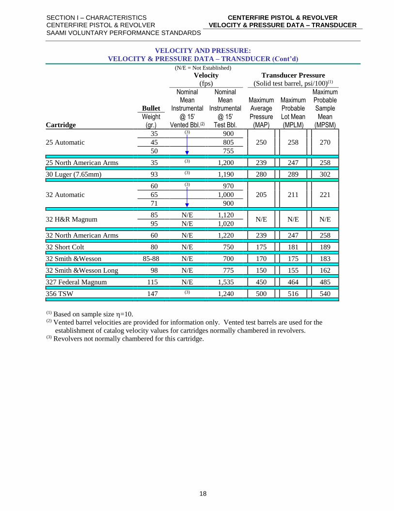
VELOCITY AND PRESSURE:
VELOCITY & PRESSURE DATA – TRANSDUCER (Cont’d)
(N/E = Not Established)
Velocity Transducer Pressure
(fps) (Solid test barrel, psi/100)(1)
Nominal Nominal Maximum Mean Mean Maximum Maximum Probable Bullet Instrumental Instrumental Average Probable Sample
Weight @ 15’ @ 15’ Pressure Lot Mean Mean Cartridge (gr.) Vented Bbl.(2) Test Bbl. (MAP) (MPLM) (MPSM)
25 Automatic
35 (3) 900
250
258
270 45 805
50 755
25 North American Arms 35 (3) 1,200 239 247 258
30 Luger (7.65mm) 93 (3) 1,190 280 289 302
32 Automatic
60 (3) 970
205
211
221 65 1,000
71 900
32 H&R Magnum 85 N/E 1,120
N/E
N/E
N/E 95 N/E 1,020
32 North American Arms 60 N/E 1,220 239 247 258
32 Short Colt 80 N/E 750 175 181 189
32 Smith &Wesson 85-88 N/E 700 170 175 183
32 Smith &Wesson Long 98 N/E 775 150 155 162
327 Federal Magnum 115 N/E 1,535 450 464 485
356 TSW 147 (3) 1,240 500 516 540
(1) Based on sample size =10. (2) Vented barrel velocities are provided for information only. Vented test barrels are used for the
establishment of catalog velocity values for cartridges normally chambered in revolvers. (3) Revolvers not normally chambered for this cartridge.
SECTION I – CHARACTERISTICS CENTERFIRE PISTOL & REVOLVER
CENTERFIRE PISTOL & REVOLVER VELOCITY & PRESSURE DATA – TRANSDUCER
SAAMI VOLUNTARY PERFORMANCE STANDARDS
19
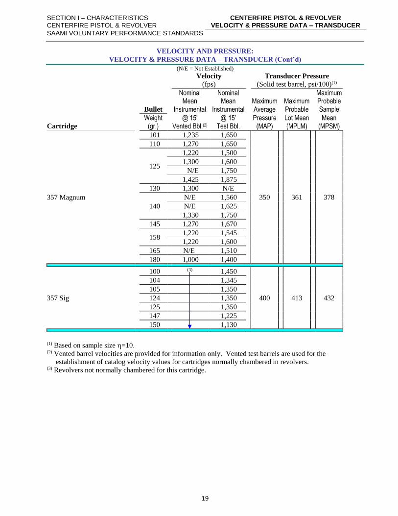
VELOCITY AND PRESSURE:
VELOCITY & PRESSURE DATA – TRANSDUCER (Cont’d)
(N/E = Not Established)
Velocity Transducer Pressure
(fps) (Solid test barrel, psi/100)(1)
Nominal Nominal Maximum Mean Mean Maximum Maximum Probable Bullet Instrumental Instrumental Average Probable Sample
Weight @ 15’ @ 15’ Pressure Lot Mean Mean Cartridge (gr.) Vented Bbl.(2) Test Bbl. (MAP) (MPLM) (MPSM)
357 Magnum
101 1,235 1,650
350 361 378
110 1,270 1,650
125
1,220 1,500
1,300 1,600
N/E 1,750
1,425 1,875
130 1,300 N/E
140
N/E 1,560
N/E 1,625
1,330 1,750
145 1,270 1,670
158
1,220 1,545
1,220 1,600
165 N/E 1,510
180 1,000 1,400
357 Sig
100 (3) 1,450
400 413 432
104 1,345
105 1,350
124 1,350
125 1,350
147 1,225
150 1,130
(1) Based on sample size =10. (2) Vented barrel velocities are provided for information only. Vented test barrels are used for the
establishment of catalog velocity values for cartridges normally chambered in revolvers. (3) Revolvers not normally chambered for this cartridge.

SECTION I – CHARACTERISTICS CENTERFIRE PISTOL & REVOLVER
CENTERFIRE PISTOL & REVOLVER VELOCITY & PRESSURE DATA – TRANSDUCER
SAAMI VOLUNTARY PERFORMANCE STANDARDS
20
VELOCITY AND PRESSURE:
VELOCITY & PRESSURE DATA – TRANSDUCER (Cont’d)
(N/E = Not Established)
Velocity Transducer Pressure
(fps) (Solid test barrel, psi/100)(1)
Nominal Nominal Maximum Mean Mean Maximum Maximum Probable Bullet Instrumental Instrumental Average Probable Sample
Weight @ 15’ @ 15’ Pressure Lot Mean Mean Cartridge (gr.) Vented Bbl.(2) Test Bbl. (MAP) (MPLM) (MPSM)
38 Automatic 130 (3) 1,035 265 273 286
38 Smith &Wesson 145-146 N/E 680 145 150 157
38 Special
100 950 N/E
170 175 183
110
1,000 N/E
N/E 975
945 1,150
125
N/E 950
N/E 1,000
N/E 1,050
130
N/E 775
775 950
895 1,040
150 N/E 900
158 750 900
200 630 780
38 Special Match(4) 148 700 800
170 175 183 158 750 900
38 Special +P
95
1,080 1,330
200 206 215
1,155 1,420
101 945 1,120
110 980 1,205
125 965 1,135
130 925 1,150
147 855 985
150 840 1,050
158 880 1,050
(1) Based on sample size =10. (2) Vented barrel velocities are provided for information only. Vented test barrels are used for the
establishment of catalog velocity values for cartridges normally chambered in revolvers. (3) Revolvers not normally chambered for this cartridge. (4) The velocity figures listed for Match items are nominal values; optimum accuracy may require a velocity
different from the nominal values.
SECTION I – CHARACTERISTICS CENTERFIRE PISTOL & REVOLVER
CENTERFIRE PISTOL & REVOLVER VELOCITY & PRESSURE DATA – TRANSDUCER
SAAMI VOLUNTARY PERFORMANCE STANDARDS
21
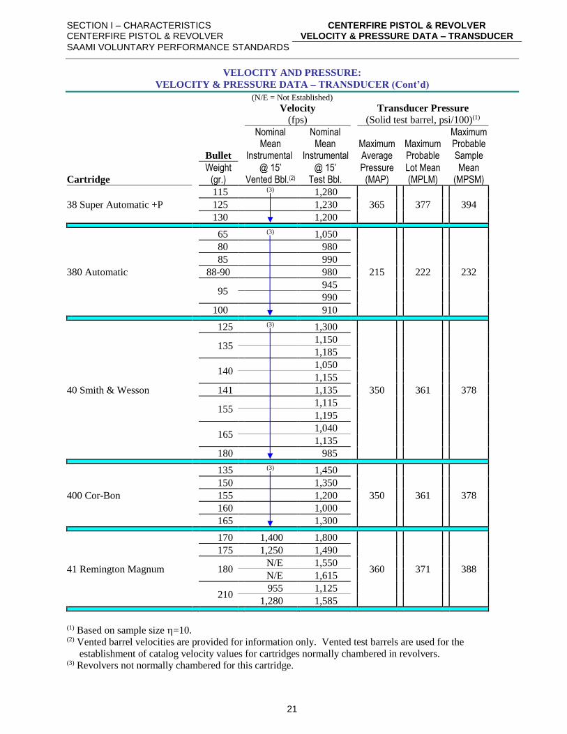
VELOCITY AND PRESSURE:
VELOCITY & PRESSURE DATA – TRANSDUCER (Cont’d)
(N/E = Not Established)
Velocity Transducer Pressure
(fps) (Solid test barrel, psi/100)(1)
Nominal Nominal Maximum Mean Mean Maximum Maximum Probable Bullet Instrumental Instrumental Average Probable Sample
Weight @ 15’ @ 15’ Pressure Lot Mean Mean Cartridge (gr.) Vented Bbl.(2) Test Bbl. (MAP) (MPLM) (MPSM)
38 Super Automatic +P
115 (3) 1,280
365 377 394 125 1,230
130 1,200
380 Automatic
65 (3) 1,050
215 222 232
80 980
85 990
88-90 980
95
945
990
100 910
40 Smith & Wesson
125 (3) 1,300
350 361 378
135
1,150
1,185
140
1,050
1,155
141 1,135
155
1,115
1,195
165
1,040
1,135
180 985
400 Cor-Bon
135 (3) 1,450
350 361 378
150 1,350
155 1,200
160 1,000
165 1,300
41 Remington Magnum
170 1,400 1,800
360 371 388
175 1,250 1,490
180
N/E 1,550
N/E 1,615
210
955 1,125
1,280 1,585
(1) Based on sample size =10. (2) Vented barrel velocities are provided for information only. Vented test barrels are used for the
establishment of catalog velocity values for cartridges normally chambered in revolvers. (3) Revolvers not normally chambered for this cartridge.
SECTION I – CHARACTERISTICS CENTERFIRE PISTOL & REVOLVER
CENTERFIRE PISTOL & REVOLVER VELOCITY & PRESSURE DATA – TRANSDUCER
SAAMI VOLUNTARY PERFORMANCE STANDARDS
22
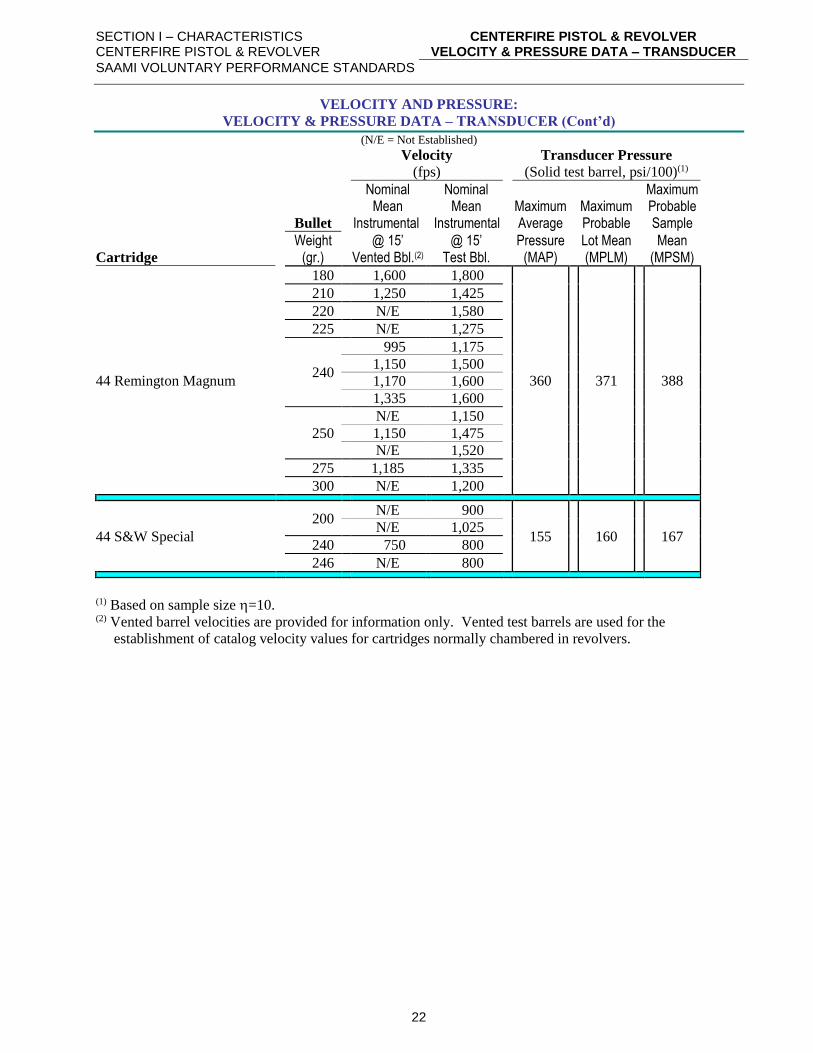
VELOCITY AND PRESSURE:
VELOCITY & PRESSURE DATA – TRANSDUCER (Cont’d)
(N/E = Not Established)
Velocity Transducer Pressure
(fps) (Solid test barrel, psi/100)(1)
Nominal Nominal Maximum Mean Mean Maximum Maximum Probable Bullet Instrumental Instrumental Average Probable Sample
Weight @ 15’ @ 15’ Pressure Lot Mean Mean Cartridge (gr.) Vented Bbl.(2) Test Bbl. (MAP) (MPLM) (MPSM)
44 Remington Magnum
180 1,600 1,800
360
371
388
210 1,250 1,425
220 N/E 1,580
225 N/E 1,275
240
995 1,175
1,150 1,500
1,170 1,600
1,335 1,600
250
N/E 1,150
1,150 1,475
N/E 1,520
275 1,185 1,335
300 N/E 1,200
44 S&W Special
200
N/E 900
155
160
167 N/E 1,025
240 750 800
246 N/E 800
(1) Based on sample size =10. (2) Vented barrel velocities are provided for information only. Vented test barrels are used for the
establishment of catalog velocity values for cartridges normally chambered in revolvers.
SECTION I – CHARACTERISTICS CENTERFIRE PISTOL & REVOLVER
CENTERFIRE PISTOL & REVOLVER VELOCITY & PRESSURE DATA – TRANSDUCER
SAAMI VOLUNTARY PERFORMANCE STANDARDS
23
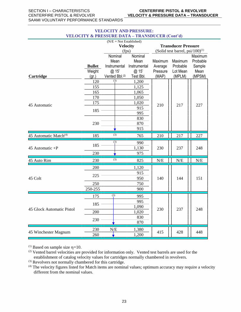
VELOCITY AND PRESSURE:
VELOCITY & PRESSURE DATA – TRANSDUCER (Cont’d)
(N/E = Not Established)
Velocity Transducer Pressure
(fps) (Solid test barrel, psi/100)(1)
Nominal Nominal Maximum Mean Mean Maximum Maximum Probable Bullet Instrumental Instrumental Average Probable Sample
Weight @ 15’ @ 15’ Pressure Lot Mean Mean Cartridge (gr.) Vented Bbl.(2) Test Bbl. (MAP) (MPLM) (MPSM)
45 Automatic
120 (3) 1,200
210 217 227
155 1,125
165 1,065
170 1,050
175 1,020
185
915
995
230
830
870
915
45 Automatic Match(4) 185 (3) 765 210 217 227
45 Automatic +P
185
(3) 990
230 237 248 1,130
230 975
45 Auto Rim 230 (3) 825 N/E N/E N/E
45 Colt
200 1,120
140 144 151
225
915
950
250 750
250-255 900
45 Glock Automatic Pistol
175 (3) 995
230 237 248
185
995
1,090
200 1,020
230
830
870
45 Winchester Magnum 230 N/E 1,380
415 428 448 260 1,200
(1) Based on sample size =10. (2) Vented barrel velocities are provided for information only. Vented test barrels are used for the
establishment of catalog velocity values for cartridges normally chambered in revolvers. (3) Revolvers not normally chambered for this cartridge. (4) The velocity figures listed for Match items are nominal values; optimum accuracy may require a velocity
different from the nominal values.
SECTION I – CHARACTERISTICS CENTERFIRE PISTOL & REVOLVER
CENTERFIRE PISTOL & REVOLVER VELOCITY & PRESSURE DATA – TRANSDUCER
SAAMI VOLUNTARY PERFORMANCE STANDARDS
24
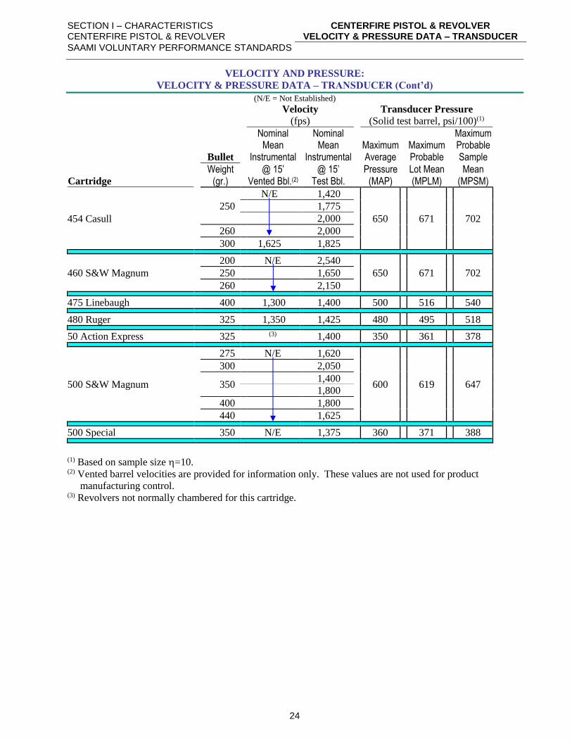
VELOCITY AND PRESSURE:
VELOCITY & PRESSURE DATA – TRANSDUCER (Cont’d)
(N/E = Not Established)
Velocity Transducer Pressure
(fps) (Solid test barrel, psi/100)(1)
Nominal Nominal Maximum Mean Mean Maximum Maximum Probable Bullet Instrumental Instrumental Average Probable Sample
Weight @ 15’ @ 15’ Pressure Lot Mean Mean Cartridge (gr.) Vented Bbl.(2) Test Bbl. (MAP) (MPLM) (MPSM)
454 Casull
250
N/E 1,420
650 671 702
1,775
2,000
260 2,000
300 1,625 1,825
460 S&W Magnum
200 N/E 2,540
650 671 702 250 1,650
260 2,150
475 Linebaugh 400 1,300 1,400 500 516 540
480 Ruger 325 1,350 1,425 480 495 518
50 Action Express 325 (3) 1,400 350 361 378
500 S&W Magnum
275 N/E 1,620
600 619 647
300 2,050
350
1,400
1,800
400 1,800
440 1,625
500 Special 350 N/E 1,375 360 371 388
(1) Based on sample size =10. (2) Vented barrel velocities are provided for information only. These values are not used for product
manufacturing control. (3) Revolvers not normally chambered for this cartridge.
SECTION I – CHARACTERISTICS CENTERFIRE PISTOL & REVOLVER
BULLET TYPE ABBREVIATIONS
SAAMI VOLUNTARY PERFORMANCE STANDARDS
25
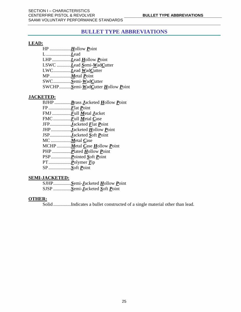
BULLET TYPE ABBREVIATIONS
LEAD:
HP ..................Hollow Point
L .....................Lead
LHP ................Lead Hollow Point
LSWC ............Lead Semi-WadCutter
LWC ...............Lead WadCutter
MP ..................Metal Point
SWC ...............Semi-WadCutter
SWCHP ..........Semi-WadCutter Hollow Point
JACKETED:
BJHP ..............Brass Jacketed Hollow Point
FP ...................Flat Point
FMJ ................Full Metal Jacket
FMC ...............Full Metal Case
JFP..................Jacketed Flat Point
JHP .................Jacketed Hollow Point
JSP..................Jacketed Soft Point
MC .................Metal Case
MCHP ............Metal Case Hollow Point
PHP ................Plated Hollow Point
PSP .................Pointed Soft Point
PT ...................Polymer Tip
SP ...................Soft Point
SEMI-JACKETED:
SJHP ...............Semi-Jacketed Hollow Point
SJSP ...............Semi-Jacketed Soft Point
OTHER:
Solid ...............Indicates a bullet constructed of a single material other than lead.
SECTION I – CHARACTERISTICS CENTERFIRE PISTOL & REVOLVER
PRIMERS AND PRIMER POCKETS
SAAMI VOLUNTARY PERFORMANCE STANDARDS
26
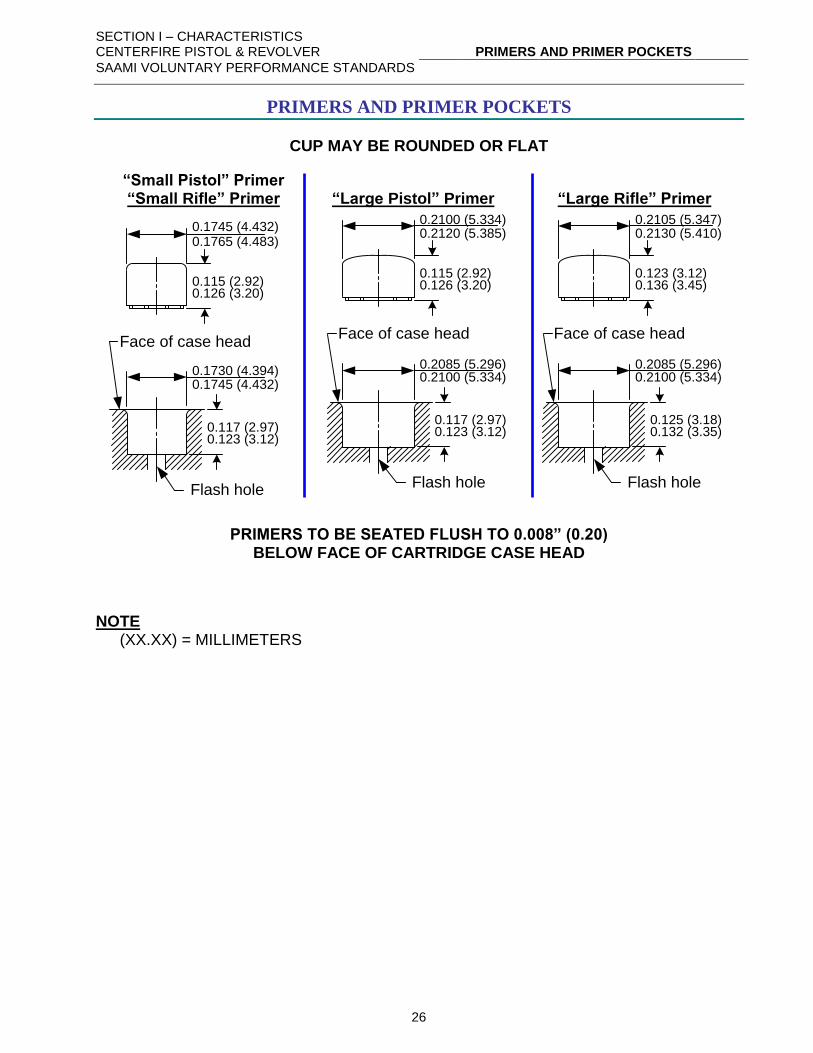
PRIMERS AND PRIMER POCKETS
CUP MAY BE ROUNDED OR FLAT
“Small Pistol” Primer “Small Rifle” Primer “Large Pistol” Primer “Large Rifle” Primer
0.1745 (4.432)0.1765 (4.483)
0.115 (2.92)0.126 (3.20)
0.2100 (5.334)0.2120 (5.385)
0.115 (2.92)0.126 (3.20)
0.117 (2.97)0.123 (3.12)
Face of case head
0.1730 (4.394)0.1745 (4.432)
Flash hole
0.117 (2.97)0.123 (3.12)
Face of case head
0.2085 (5.296)0.2100 (5.334)
Flash hole
0.2105 (5.347)0.2130 (5.410)
0.123 (3.12)0.136 (3.45)
0.125 (3.18)0.132 (3.35)
Face of case head
0.2085 (5.296)0.2100 (5.334)
Flash hole
PRIMERS TO BE SEATED FLUSH TO 0.008” (0.20) BELOW FACE OF CARTRIDGE CASE HEAD
NOTE (XX.XX) = MILLIMETERS
SECTION I – CHARACTERISTICS CENTERFIRE PISTOL & REVOLVER
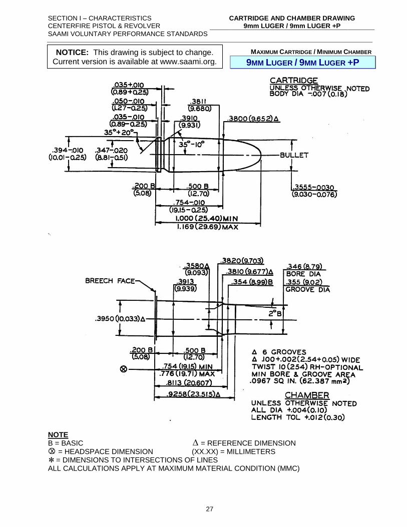
CARTRIDGE AND CHAMBER DRAWING 9mm LUGER / 9mm LUGER +P
SAAMI VOLUNTARY PERFORMANCE STANDARDS
27
MAXIMUM CARTRIDGE / MINIMUM CHAMBER
9MM LUGER / 9MM LUGER +P
NOTE B = BASIC = REFERENCE DIMENSION = HEADSPACE DIMENSION (XX.XX) = MILLIMETERS = DIMENSIONS TO INTERSECTIONS OF LINES ALL CALCULATIONS APPLY AT MAXIMUM MATERIAL CONDITION (MMC)
X
NOTICE: This drawing is subject to change. Current version is available at www.saami.org.
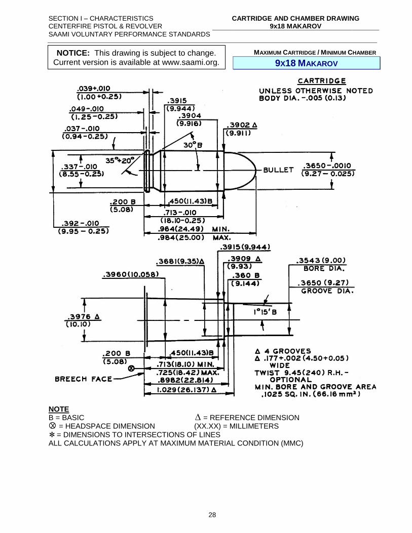
SECTION I – CHARACTERISTICS CENTERFIRE PISTOL & REVOLVER
CARTRIDGE AND CHAMBER DRAWING 9x18 MAKAROV
SAAMI VOLUNTARY PERFORMANCE STANDARDS
28
MAXIMUM CARTRIDGE / MINIMUM CHAMBER
9X18 MAKAROV
NOTE B = BASIC = REFERENCE DIMENSION = HEADSPACE DIMENSION (XX.XX) = MILLIMETERS = DIMENSIONS TO INTERSECTIONS OF LINES ALL CALCULATIONS APPLY AT MAXIMUM MATERIAL CONDITION (MMC)
X
NOTICE: This drawing is subject to change. Current version is available at www.saami.org.
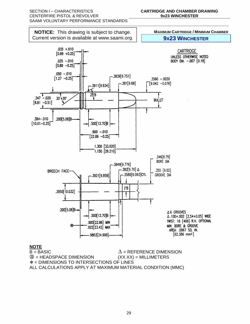
SECTION I – CHARACTERISTICS CENTERFIRE PISTOL & REVOLVER
CARTRIDGE AND CHAMBER DRAWING 9x23 WINCHESTER
SAAMI VOLUNTARY PERFORMANCE STANDARDS
29
MAXIMUM CARTRIDGE / MINIMUM CHAMBER
9X23 WINCHESTER
NOTE B = BASIC = REFERENCE DIMENSION = HEADSPACE DIMENSION (XX.XX) = MILLIMETERS = DIMENSIONS TO INTERSECTIONS OF LINES ALL CALCULATIONS APPLY AT MAXIMUM MATERIAL CONDITION (MMC)
X
NOTICE: This drawing is subject to change. Current version is available at www.saami.org.
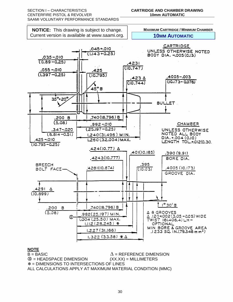
SECTION I – CHARACTERISTICS CENTERFIRE PISTOL & REVOLVER
CARTRIDGE AND CHAMBER DRAWING 10mm AUTOMATIC
SAAMI VOLUNTARY PERFORMANCE STANDARDS
30
MAXIMUM CARTRIDGE / MINIMUM CHAMBER
10MM AUTOMATIC
NOTE B = BASIC = REFERENCE DIMENSION = HEADSPACE DIMENSION (XX.XX) = MILLIMETERS = DIMENSIONS TO INTERSECTIONS OF LINES ALL CALCULATIONS APPLY AT MAXIMUM MATERIAL CONDITION (MMC)
X
NOTICE: This drawing is subject to change. Current version is available at www.saami.org.
SECTION I – CHARACTERISTICS CENTERFIRE PISTOL & REVOLVER
CARTRIDGE AND CHAMBER DRAWING 221 REMINGTON FIREBALL
SAAMI VOLUNTARY PERFORMANCE STANDARDS
31
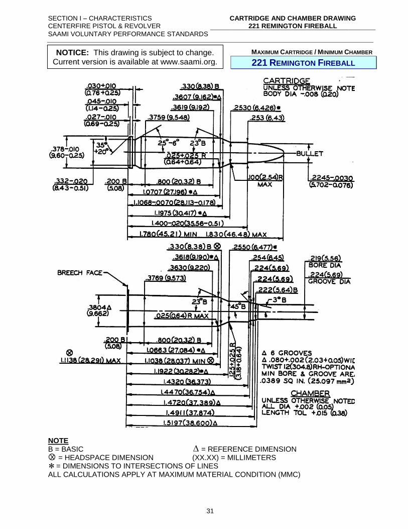
MAXIMUM CARTRIDGE / MINIMUM CHAMBER
221 REMINGTON FIREBALL
NOTE B = BASIC = REFERENCE DIMENSION = HEADSPACE DIMENSION (XX.XX) = MILLIMETERS = DIMENSIONS TO INTERSECTIONS OF LINES ALL CALCULATIONS APPLY AT MAXIMUM MATERIAL CONDITION (MMC)
X
NOTICE: This drawing is subject to change. Current version is available at www.saami.org.
SECTION I – CHARACTERISTICS CENTERFIRE PISTOL & REVOLVER
CARTRIDGE AND CHAMBER DRAWING 25 AUTOMATIC
SAAMI VOLUNTARY PERFORMANCE STANDARDS
32
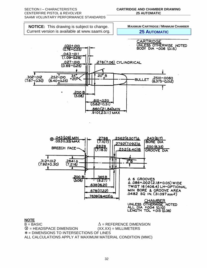
MAXIMUM CARTRIDGE / MINIMUM CHAMBER
25 AUTOMATIC
NOTE B = BASIC = REFERENCE DIMENSION = HEADSPACE DIMENSION (XX.XX) = MILLIMETERS = DIMENSIONS TO INTERSECTIONS OF LINES ALL CALCULATIONS APPLY AT MAXIMUM MATERIAL CONDITION (MMC)
X
NOTICE: This drawing is subject to change. Current version is available at www.saami.org.
SECTION I – CHARACTERISTICS CENTERFIRE PISTOL & REVOLVER
CARTRIDGE AND CHAMBER DRAWING 25 NORTH AMERICAN ARMS
SAAMI VOLUNTARY PERFORMANCE STANDARDS
33
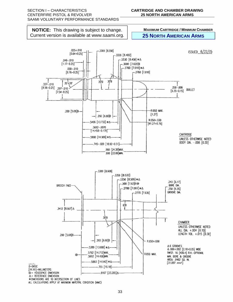
MAXIMUM CARTRIDGE / MINIMUM CHAMBER
25 NORTH AMERICAN ARMS
NOTICE: This drawing is subject to change. Current version is available at www.saami.org.
SECTION I – CHARACTERISTICS CENTERFIRE PISTOL & REVOLVER
CARTRIDGE AND CHAMBER DRAWING 30 LUGER (7.65mm)
SAAMI VOLUNTARY PERFORMANCE STANDARDS
34
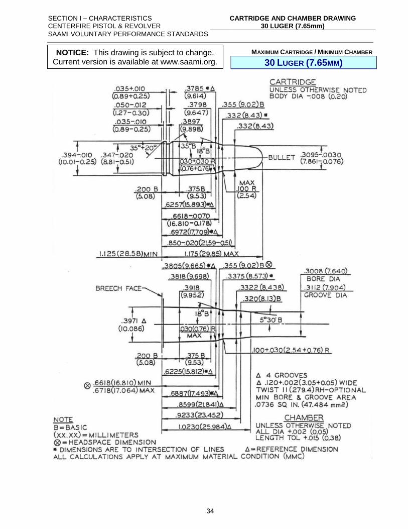
MAXIMUM CARTRIDGE / MINIMUM CHAMBER
30 LUGER (7.65MM)
NOTICE: This drawing is subject to change. Current version is available at www.saami.org.
SECTION I – CHARACTERISTICS CENTERFIRE PISTOL & REVOLVER
CARTRIDGE AND CHAMBER DRAWING 32 AUTOMATIC
SAAMI VOLUNTARY PERFORMANCE STANDARDS
35
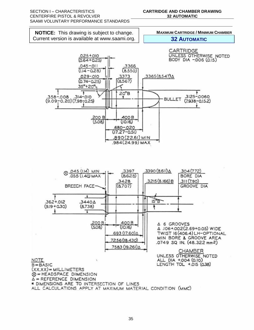
MAXIMUM CARTRIDGE / MINIMUM CHAMBER
32 AUTOMATIC
NOTICE: This drawing is subject to change. Current version is available at www.saami.org.
SECTION I – CHARACTERISTICS CENTERFIRE PISTOL & REVOLVER
CARTRIDGE AND CHAMBER DRAWING 32 H&R MAGNUM
SAAMI VOLUNTARY PERFORMANCE STANDARDS
36
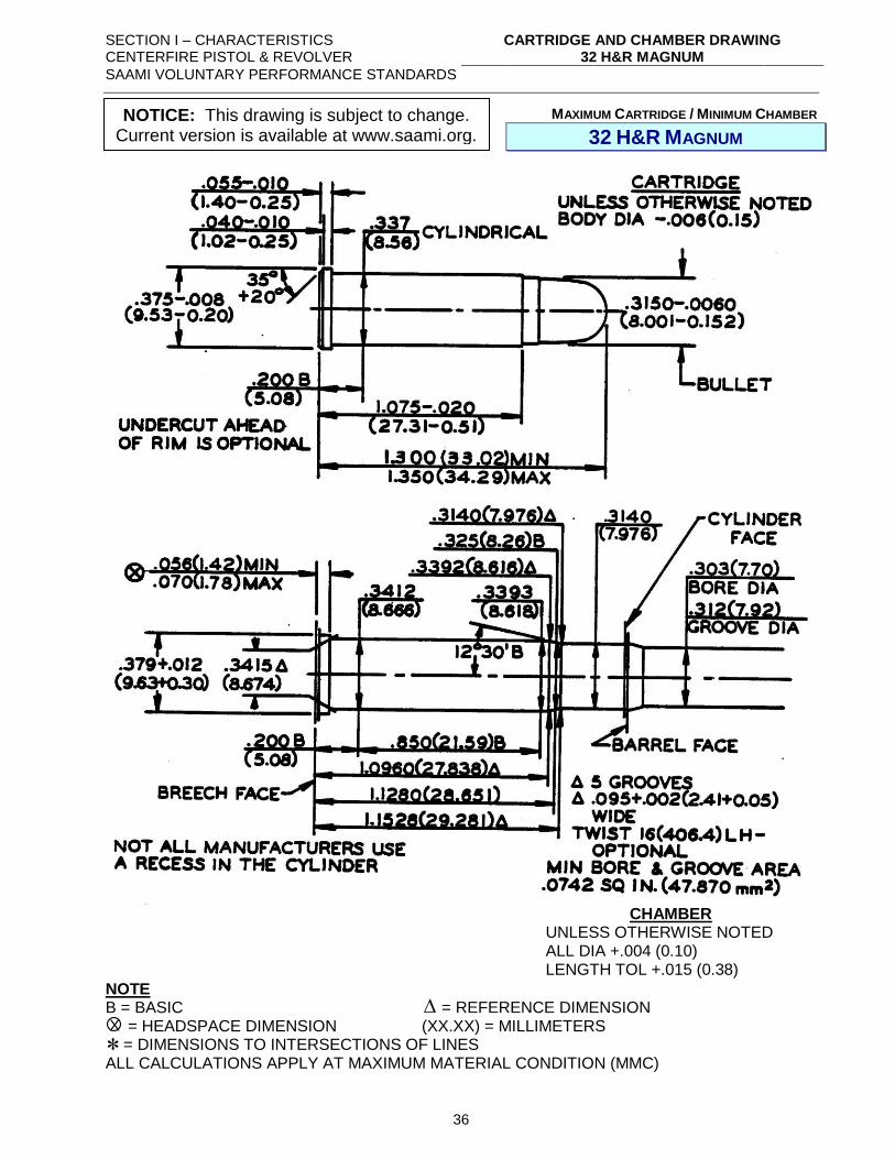
MAXIMUM CARTRIDGE / MINIMUM CHAMBER
32 H&R MAGNUM
NOTE B = BASIC = REFERENCE DIMENSION = HEADSPACE DIMENSION (XX.XX) = MILLIMETERS = DIMENSIONS TO INTERSECTIONS OF LINES ALL CALCULATIONS APPLY AT MAXIMUM MATERIAL CONDITION (MMC)
CHAMBER UNLESS OTHERWISE NOTED ALL DIA +.004 (0.10) LENGTH TOL +.015 (0.38)
X
NOTICE: This drawing is subject to change. Current version is available at www.saami.org.
SECTION I – CHARACTERISTICS CENTERFIRE PISTOL & REVOLVER
CARTRIDGE AND CHAMBER DRAWING 32 NORTH AMERICAN ARMS
SAAMI VOLUNTARY PERFORMANCE STANDARDS
37
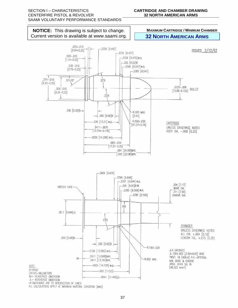
MAXIMUM CARTRIDGE / MINIMUM CHAMBER
32 NORTH AMERICAN ARMS
NOTICE: This drawing is subject to change. Current version is available at www.saami.org.
SECTION I – CHARACTERISTICS CENTERFIRE PISTOL & REVOLVER
CARTRIDGE AND CHAMBER DRAWING 32 SHORT COLT
SAAMI VOLUNTARY PERFORMANCE STANDARDS
38
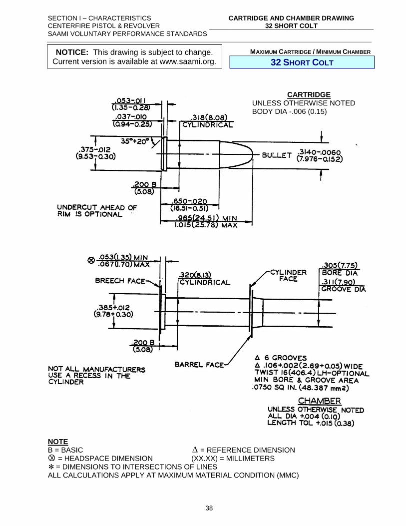
MAXIMUM CARTRIDGE / MINIMUM CHAMBER
32 SHORT COLT
NOTE B = BASIC = REFERENCE DIMENSION = HEADSPACE DIMENSION (XX.XX) = MILLIMETERS = DIMENSIONS TO INTERSECTIONS OF LINES ALL CALCULATIONS APPLY AT MAXIMUM MATERIAL CONDITION (MMC)
CARTRIDGE UNLESS OTHERWISE NOTED BODY DIA -.006 (0.15)
X
NOTICE: This drawing is subject to change. Current version is available at www.saami.org.
SECTION I – CHARACTERISTICS CENTERFIRE PISTOL & REVOLVER
CARTRIDGE AND CHAMBER DRAWING 32 SMITH & WESSON
SAAMI VOLUNTARY PERFORMANCE STANDARDS
39
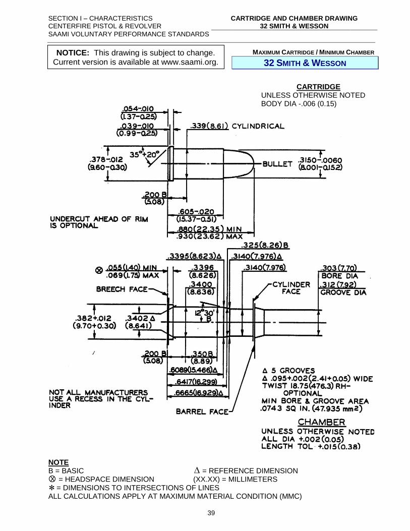
MAXIMUM CARTRIDGE / MINIMUM CHAMBER
32 SMITH & WESSON
NOTE B = BASIC = REFERENCE DIMENSION = HEADSPACE DIMENSION (XX.XX) = MILLIMETERS = DIMENSIONS TO INTERSECTIONS OF LINES ALL CALCULATIONS APPLY AT MAXIMUM MATERIAL CONDITION (MMC)
CARTRIDGE UNLESS OTHERWISE NOTED BODY DIA -.006 (0.15)
X
NOTICE: This drawing is subject to change. Current version is available at www.saami.org.
SECTION I – CHARACTERISTICS CENTERFIRE PISTOL & REVOLVER
CARTRIDGE AND CHAMBER DRAWING 32 SMITH & WESSON LONG
(32 COLT NEW POLICE)
SAAMI VOLUNTARY PERFORMANCE STANDARDS
40
MAXIMUM CARTRIDGE / MINIMUM CHAMBER
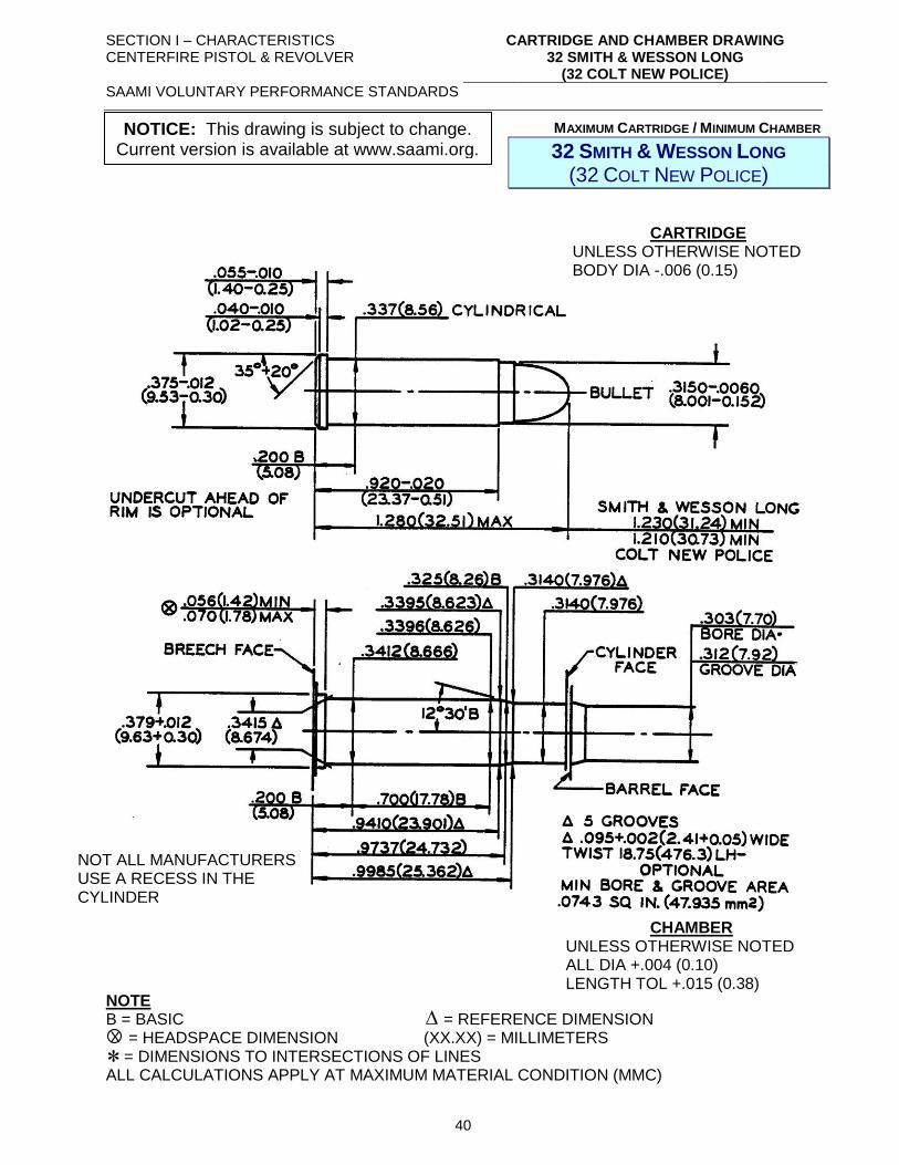
32 SMITH & WESSON LONG (32 COLT NEW POLICE)
NOTE B = BASIC = REFERENCE DIMENSION = HEADSPACE DIMENSION (XX.XX) = MILLIMETERS = DIMENSIONS TO INTERSECTIONS OF LINES ALL CALCULATIONS APPLY AT MAXIMUM MATERIAL CONDITION (MMC)
CARTRIDGE UNLESS OTHERWISE NOTED BODY DIA -.006 (0.15)
CHAMBER UNLESS OTHERWISE NOTED ALL DIA +.004 (0.10) LENGTH TOL +.015 (0.38)
NOT ALL MANUFACTURERS USE A RECESS IN THE CYLINDER
X
NOTICE: This drawing is subject to change. Current version is available at www.saami.org.
SECTION I – CHARACTERISTICS CENTERFIRE PISTOL & REVOLVER
CARTRIDGE AND CHAMBER DRAWING 32 SMITH & WESSON LONG WADCUTTER
SAAMI VOLUNTARY PERFORMANCE STANDARDS
41
MAXIMUM CARTRIDGE / MINIMUM CHAMBER
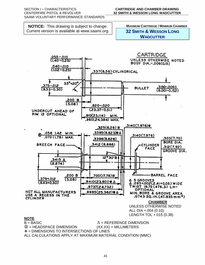
32 SMITH & WESSON LONG
WADCUTTER
NOTE B = BASIC = REFERENCE DIMENSION = HEADSPACE DIMENSION (XX.XX) = MILLIMETERS = DIMENSIONS TO INTERSECTIONS OF LINES ALL CALCULATIONS APPLY AT MAXIMUM MATERIAL CONDITION (MMC)
CHAMBER UNLESS OTHERWISE NOTED ALL DIA +.004 (0.10) LENGTH TOL +.015 (0.38)
X
NOTICE: This drawing is subject to change. Current version is available at www.saami.org.
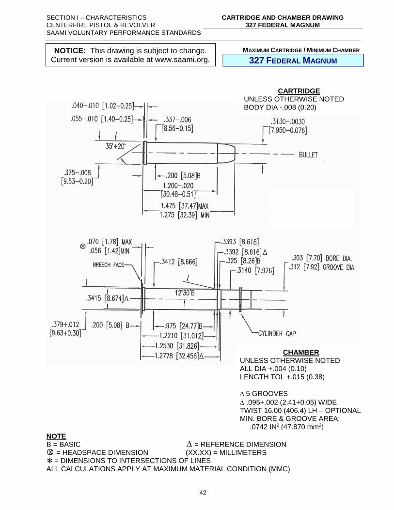
SECTION I – CHARACTERISTICS CENTERFIRE PISTOL & REVOLVER
CARTRIDGE AND CHAMBER DRAWING 327 FEDERAL MAGNUM
SAAMI VOLUNTARY PERFORMANCE STANDARDS
42
MAXIMUM CARTRIDGE / MINIMUM CHAMBER
327 FEDERAL MAGNUM
NOTE B = BASIC = REFERENCE DIMENSION = HEADSPACE DIMENSION (XX.XX) = MILLIMETERS = DIMENSIONS TO INTERSECTIONS OF LINES ALL CALCULATIONS APPLY AT MAXIMUM MATERIAL CONDITION (MMC)
CARTRIDGE UNLESS OTHERWISE NOTED BODY DIA -.008 (0.20)
CHAMBER UNLESS OTHERWISE NOTED ALL DIA +.004 (0.10) LENGTH TOL +.015 (0.38)
5 GROOVES
.095+.002 (2.41+0.05) WIDE TWIST 16.00 (406.4) LH – OPTIONAL MIN. BORE & GROOVE AREA: .0742 IN2 (47.870 mm2)
X
NOTICE: This drawing is subject to change. Current version is available at www.saami.org.
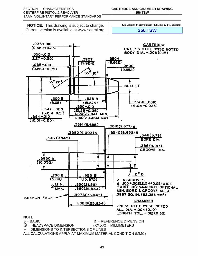
SECTION I – CHARACTERISTICS CENTERFIRE PISTOL & REVOLVER
CARTRIDGE AND CHAMBER DRAWING 356 TSW
SAAMI VOLUNTARY PERFORMANCE STANDARDS
43
MAXIMUM CARTRIDGE / MINIMUM CHAMBER
356 TSW
NOTE B = BASIC = REFERENCE DIMENSION = HEADSPACE DIMENSION (XX.XX) = MILLIMETERS = DIMENSIONS TO INTERSECTIONS OF LINES ALL CALCULATIONS APPLY AT MAXIMUM MATERIAL CONDITION (MMC)
X
NOTICE: This drawing is subject to change. Current version is available at www.saami.org.
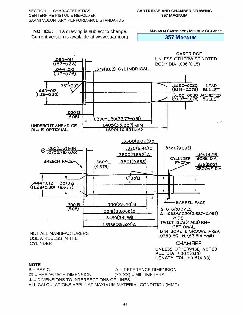
SECTION I – CHARACTERISTICS CENTERFIRE PISTOL & REVOLVER
CARTRIDGE AND CHAMBER DRAWING 357 MAGNUM
SAAMI VOLUNTARY PERFORMANCE STANDARDS
44
MAXIMUM CARTRIDGE / MINIMUM CHAMBER
357 MAGNUM
NOTE B = BASIC = REFERENCE DIMENSION = HEADSPACE DIMENSION (XX.XX) = MILLIMETERS = DIMENSIONS TO INTERSECTIONS OF LINES ALL CALCULATIONS APPLY AT MAXIMUM MATERIAL CONDITION (MMC)
CARTRIDGE UNLESS OTHERWISE NOTED BODY DIA -.006 (0.15)
NOT ALL MANUFACTURERS USE A RECESS IN THE CYLINDER
X
NOTICE: This drawing is subject to change. Current version is available at www.saami.org.
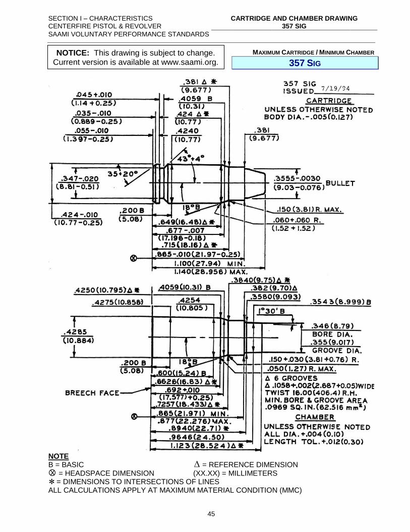
SECTION I – CHARACTERISTICS CENTERFIRE PISTOL & REVOLVER
CARTRIDGE AND CHAMBER DRAWING 357 SIG
SAAMI VOLUNTARY PERFORMANCE STANDARDS
45
MAXIMUM CARTRIDGE / MINIMUM CHAMBER
357 SIG
NOTE B = BASIC = REFERENCE DIMENSION = HEADSPACE DIMENSION (XX.XX) = MILLIMETERS = DIMENSIONS TO INTERSECTIONS OF LINES ALL CALCULATIONS APPLY AT MAXIMUM MATERIAL CONDITION (MMC)
X
NOTICE: This drawing is subject to change. Current version is available at www.saami.org.
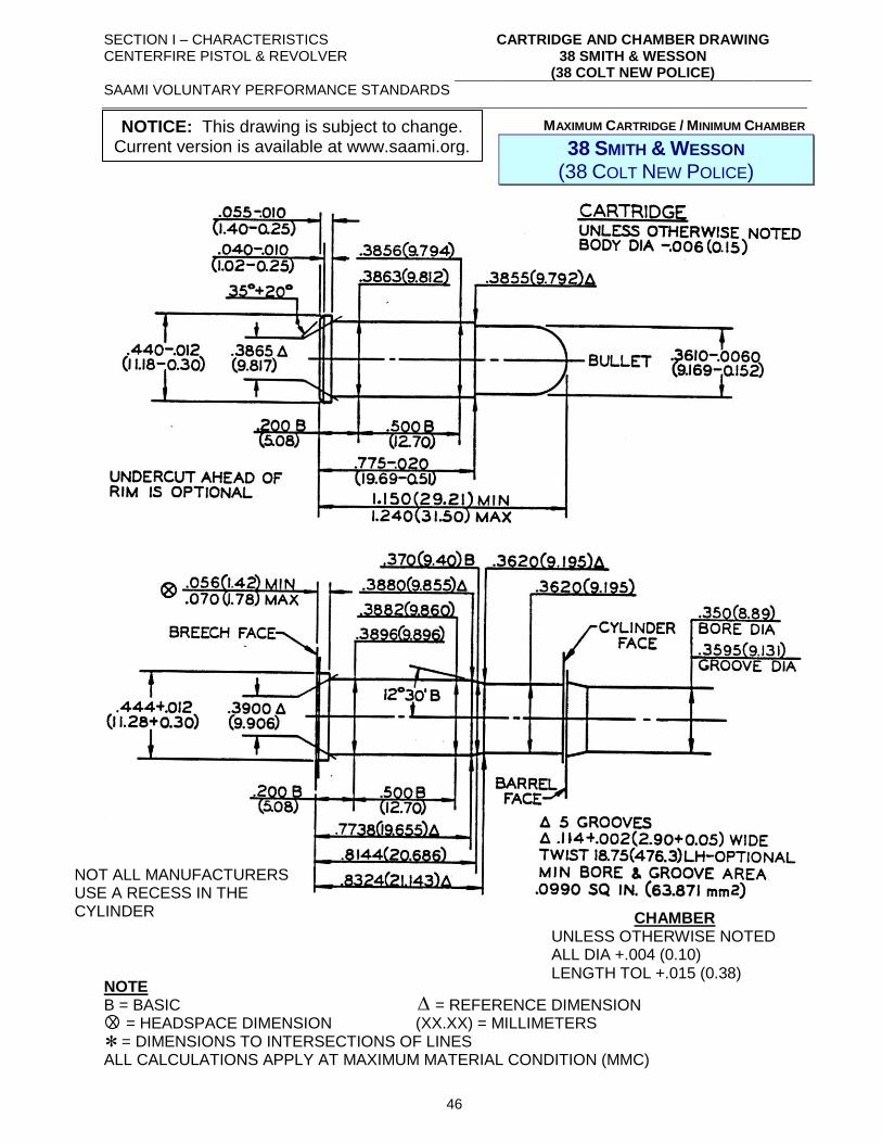
SECTION I – CHARACTERISTICS CENTERFIRE PISTOL & REVOLVER
CARTRIDGE AND CHAMBER DRAWING 38 SMITH & WESSON
(38 COLT NEW POLICE)
SAAMI VOLUNTARY PERFORMANCE STANDARDS
46
MAXIMUM CARTRIDGE / MINIMUM CHAMBER
38 SMITH & WESSON (38 COLT NEW POLICE)
NOTE B = BASIC = REFERENCE DIMENSION = HEADSPACE DIMENSION (XX.XX) = MILLIMETERS = DIMENSIONS TO INTERSECTIONS OF LINES ALL CALCULATIONS APPLY AT MAXIMUM MATERIAL CONDITION (MMC)
NOT ALL MANUFACTURERS USE A RECESS IN THE CYLINDER CHAMBER
UNLESS OTHERWISE NOTED ALL DIA +.004 (0.10) LENGTH TOL +.015 (0.38)
X
NOTICE: This drawing is subject to change. Current version is available at www.saami.org.
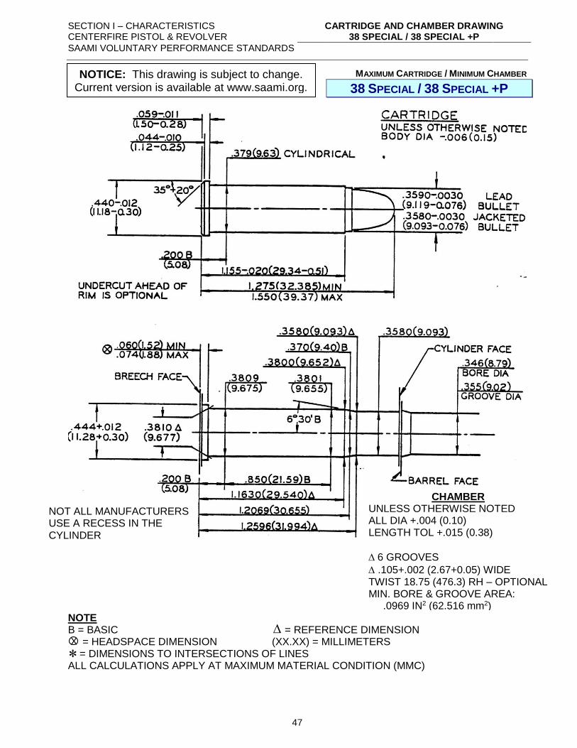
SECTION I – CHARACTERISTICS CENTERFIRE PISTOL & REVOLVER
CARTRIDGE AND CHAMBER DRAWING 38 SPECIAL / 38 SPECIAL +P
SAAMI VOLUNTARY PERFORMANCE STANDARDS
47
MAXIMUM CARTRIDGE / MINIMUM CHAMBER
38 SPECIAL / 38 SPECIAL +P
NOTE B = BASIC = REFERENCE DIMENSION = HEADSPACE DIMENSION (XX.XX) = MILLIMETERS = DIMENSIONS TO INTERSECTIONS OF LINES ALL CALCULATIONS APPLY AT MAXIMUM MATERIAL CONDITION (MMC)
NOT ALL MANUFACTURERS USE A RECESS IN THE CYLINDER
CHAMBER UNLESS OTHERWISE NOTED ALL DIA +.004 (0.10) LENGTH TOL +.015 (0.38)
6 GROOVES
.105+.002 (2.67+0.05) WIDE TWIST 18.75 (476.3) RH – OPTIONAL MIN. BORE & GROOVE AREA: .0969 IN2 (62.516 mm2)
X
NOTICE: This drawing is subject to change. Current version is available at www.saami.org.
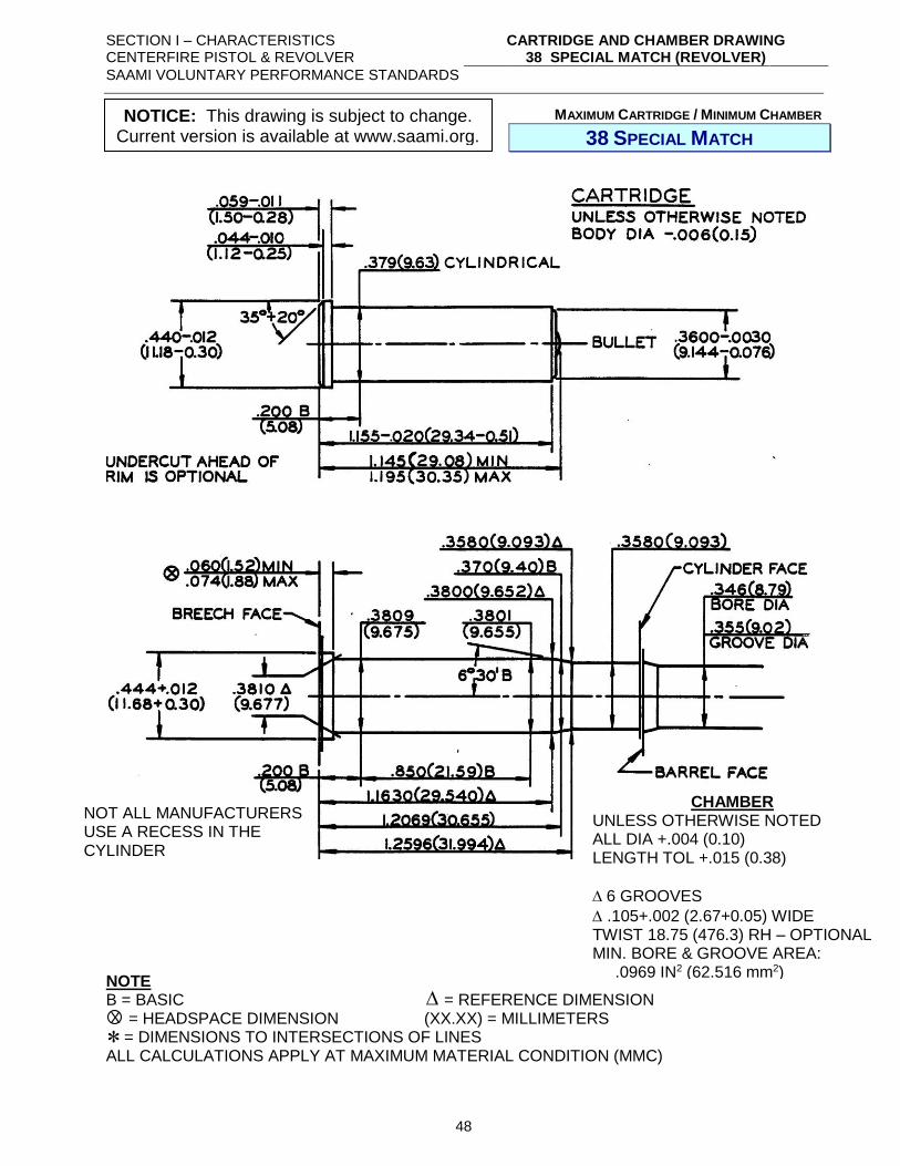
SECTION I – CHARACTERISTICS CENTERFIRE PISTOL & REVOLVER
CARTRIDGE AND CHAMBER DRAWING 38 SPECIAL MATCH (REVOLVER)
SAAMI VOLUNTARY PERFORMANCE STANDARDS
48
MAXIMUM CARTRIDGE / MINIMUM CHAMBER
38 SPECIAL MATCH
NOTE B = BASIC = REFERENCE DIMENSION = HEADSPACE DIMENSION (XX.XX) = MILLIMETERS = DIMENSIONS TO INTERSECTIONS OF LINES ALL CALCULATIONS APPLY AT MAXIMUM MATERIAL CONDITION (MMC)
NOT ALL MANUFACTURERS USE A RECESS IN THE CYLINDER
CHAMBER UNLESS OTHERWISE NOTED ALL DIA +.004 (0.10) LENGTH TOL +.015 (0.38)
6 GROOVES
.105+.002 (2.67+0.05) WIDE TWIST 18.75 (476.3) RH – OPTIONAL MIN. BORE & GROOVE AREA: .0969 IN2 (62.516 mm2)
X
NOTICE: This drawing is subject to change. Current version is available at www.saami.org.
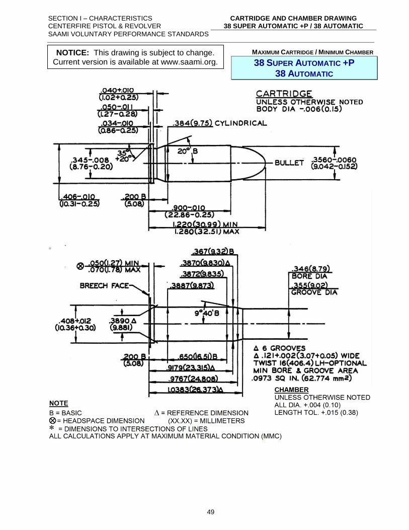
SECTION I – CHARACTERISTICS CENTERFIRE PISTOL & REVOLVER
CARTRIDGE AND CHAMBER DRAWING 38 SUPER AUTOMATIC +P / 38 AUTOMATIC
SAAMI VOLUNTARY PERFORMANCE STANDARDS
49
MAXIMUM CARTRIDGE / MINIMUM CHAMBER
38 SUPER AUTOMATIC +P 38 AUTOMATIC
NOTICE: This drawing is subject to change. Current version is available at www.saami.org.
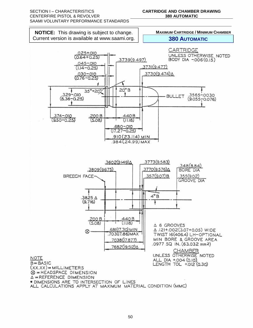
SECTION I – CHARACTERISTICS CENTERFIRE PISTOL & REVOLVER
CARTRIDGE AND CHAMBER DRAWING 380 AUTOMATIC
SAAMI VOLUNTARY PERFORMANCE STANDARDS
50
MAXIMUM CARTRIDGE / MINIMUM CHAMBER
380 AUTOMATIC
NOTICE: This drawing is subject to change. Current version is available at www.saami.org.
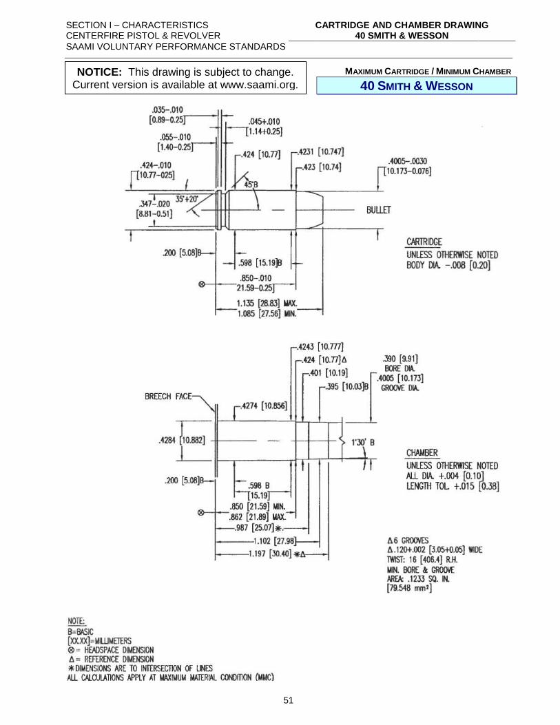
SECTION I – CHARACTERISTICS CENTERFIRE PISTOL & REVOLVER
CARTRIDGE AND CHAMBER DRAWING 40 SMITH & WESSON
SAAMI VOLUNTARY PERFORMANCE STANDARDS
51
MAXIMUM CARTRIDGE / MINIMUM CHAMBER
40 SMITH & WESSON
NOTICE: This drawing is subject to change. Current version is available at www.saami.org.
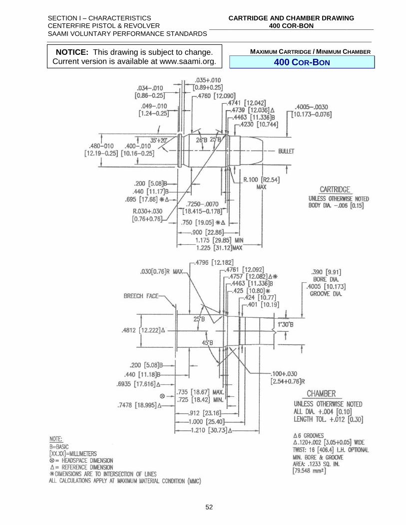
SECTION I – CHARACTERISTICS CENTERFIRE PISTOL & REVOLVER
CARTRIDGE AND CHAMBER DRAWING 400 COR-BON
SAAMI VOLUNTARY PERFORMANCE STANDARDS
52
MAXIMUM CARTRIDGE / MINIMUM CHAMBER
400 COR-BON
NOTICE: This drawing is subject to change. Current version is available at www.saami.org.
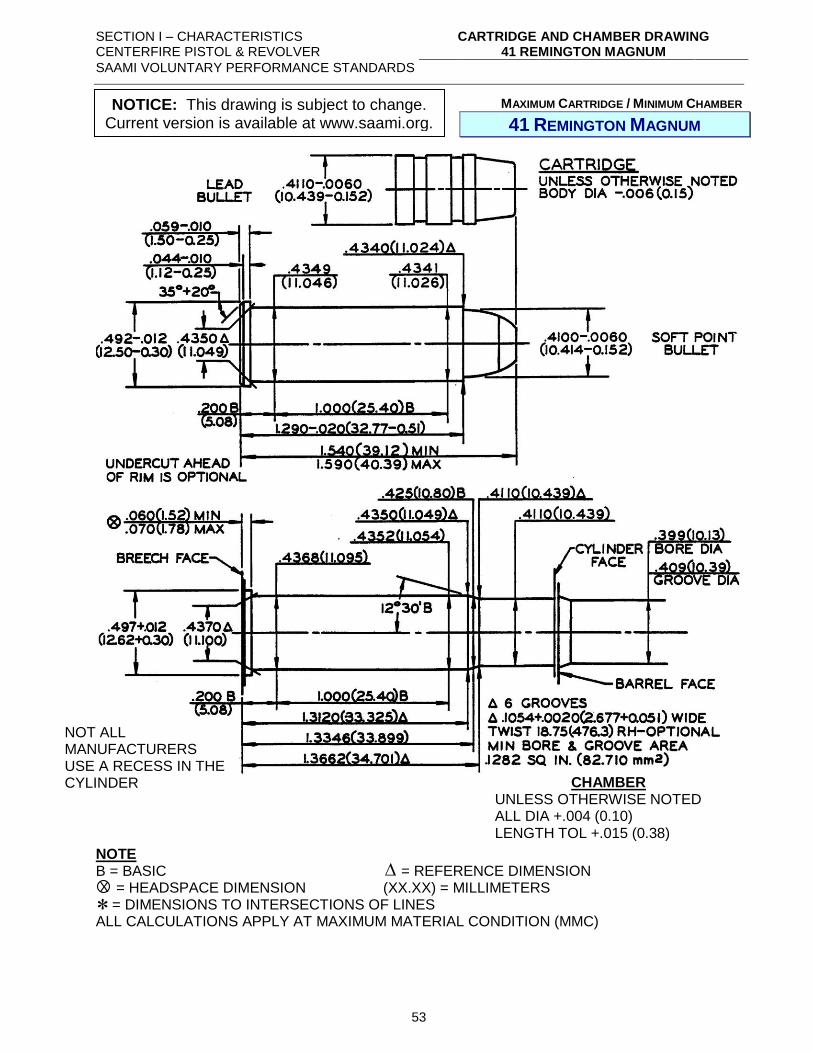
SECTION I – CHARACTERISTICS CENTERFIRE PISTOL & REVOLVER
CARTRIDGE AND CHAMBER DRAWING 41 REMINGTON MAGNUM
SAAMI VOLUNTARY PERFORMANCE STANDARDS
53
MAXIMUM CARTRIDGE / MINIMUM CHAMBER
41 REMINGTON MAGNUM
NOTE B = BASIC = REFERENCE DIMENSION = HEADSPACE DIMENSION (XX.XX) = MILLIMETERS = DIMENSIONS TO INTERSECTIONS OF LINES ALL CALCULATIONS APPLY AT MAXIMUM MATERIAL CONDITION (MMC)
NOT ALL MANUFACTURERS USE A RECESS IN THE CYLINDER CHAMBER
UNLESS OTHERWISE NOTED ALL DIA +.004 (0.10) LENGTH TOL +.015 (0.38)
X
NOTICE: This drawing is subject to change. Current version is available at www.saami.org.
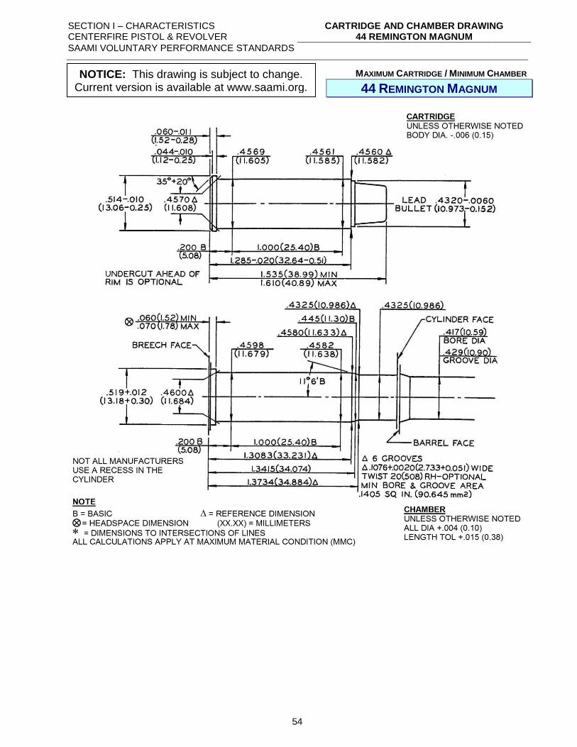
SECTION I – CHARACTERISTICS CENTERFIRE PISTOL & REVOLVER
CARTRIDGE AND CHAMBER DRAWING 44 REMINGTON MAGNUM
SAAMI VOLUNTARY PERFORMANCE STANDARDS
54
MAXIMUM CARTRIDGE / MINIMUM CHAMBER
44 REMINGTON MAGNUM
NOTICE: This drawing is subject to change. Current version is available at www.saami.org.
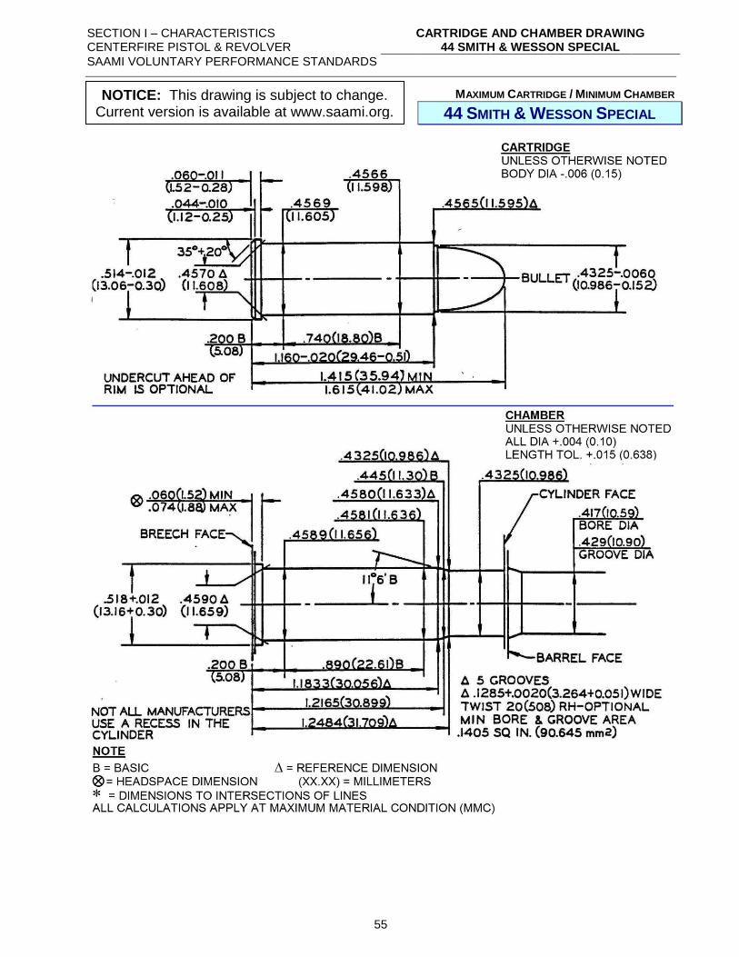
SECTION I – CHARACTERISTICS CENTERFIRE PISTOL & REVOLVER
CARTRIDGE AND CHAMBER DRAWING 44 SMITH & WESSON SPECIAL
SAAMI VOLUNTARY PERFORMANCE STANDARDS
55
MAXIMUM CARTRIDGE / MINIMUM CHAMBER
44 SMITH & WESSON SPECIAL
NOTICE: This drawing is subject to change. Current version is available at www.saami.org.
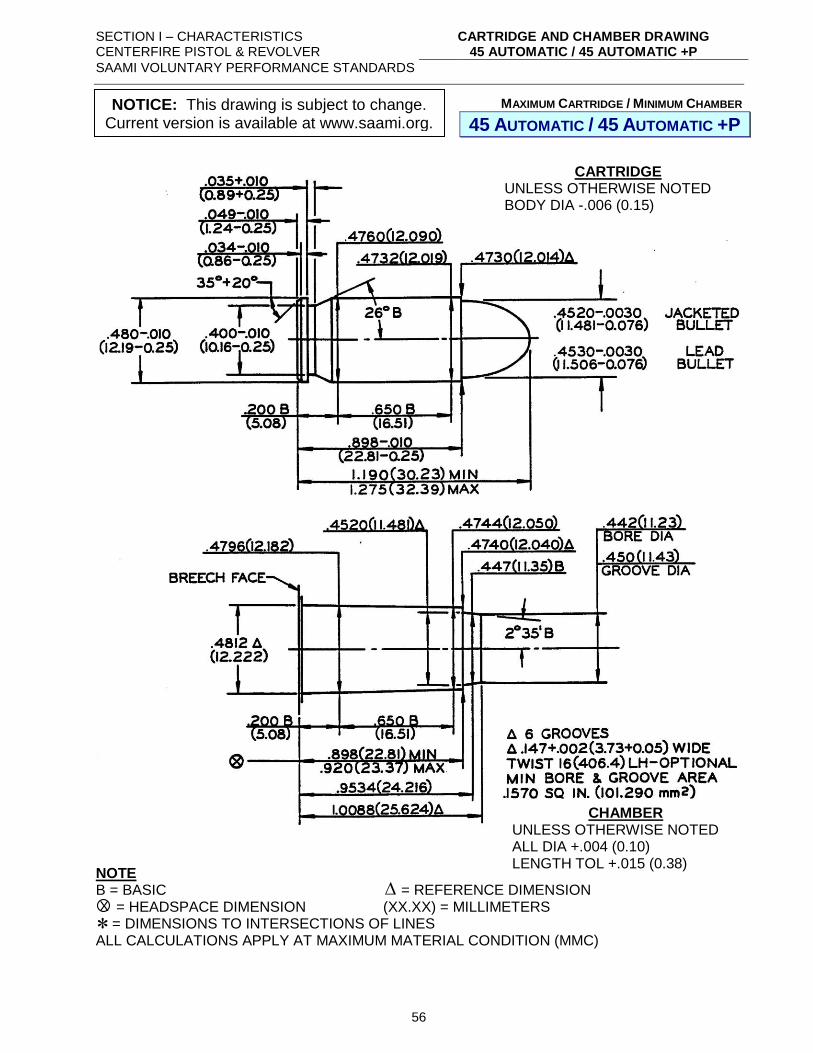
SECTION I – CHARACTERISTICS CENTERFIRE PISTOL & REVOLVER
CARTRIDGE AND CHAMBER DRAWING 45 AUTOMATIC / 45 AUTOMATIC +P
SAAMI VOLUNTARY PERFORMANCE STANDARDS
56
MAXIMUM CARTRIDGE / MINIMUM CHAMBER
45 AUTOMATIC / 45 AUTOMATIC +P
NOTE B = BASIC = REFERENCE DIMENSION = HEADSPACE DIMENSION (XX.XX) = MILLIMETERS = DIMENSIONS TO INTERSECTIONS OF LINES ALL CALCULATIONS APPLY AT MAXIMUM MATERIAL CONDITION (MMC)
X
CHAMBER UNLESS OTHERWISE NOTED ALL DIA +.004 (0.10) LENGTH TOL +.015 (0.38)
CARTRIDGE UNLESS OTHERWISE NOTED BODY DIA -.006 (0.15)
NOTICE: This drawing is subject to change. Current version is available at www.saami.org.
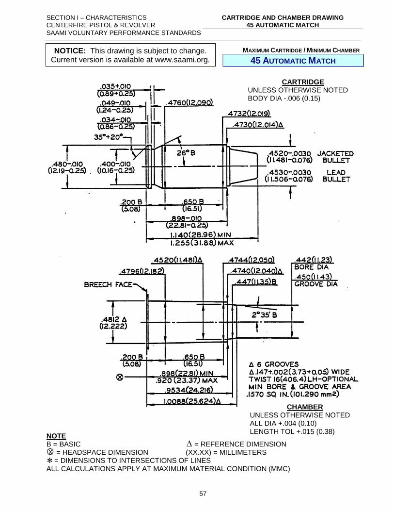
SECTION I – CHARACTERISTICS CENTERFIRE PISTOL & REVOLVER
CARTRIDGE AND CHAMBER DRAWING 45 AUTOMATIC MATCH
SAAMI VOLUNTARY PERFORMANCE STANDARDS
57
MAXIMUM CARTRIDGE / MINIMUM CHAMBER
45 AUTOMATIC MATCH
NOTE B = BASIC = REFERENCE DIMENSION = HEADSPACE DIMENSION (XX.XX) = MILLIMETERS = DIMENSIONS TO INTERSECTIONS OF LINES ALL CALCULATIONS APPLY AT MAXIMUM MATERIAL CONDITION (MMC)
CARTRIDGE UNLESS OTHERWISE NOTED BODY DIA -.006 (0.15)
CHAMBER UNLESS OTHERWISE NOTED ALL DIA +.004 (0.10) LENGTH TOL +.015 (0.38)
X
NOTICE: This drawing is subject to change. Current version is available at www.saami.org.
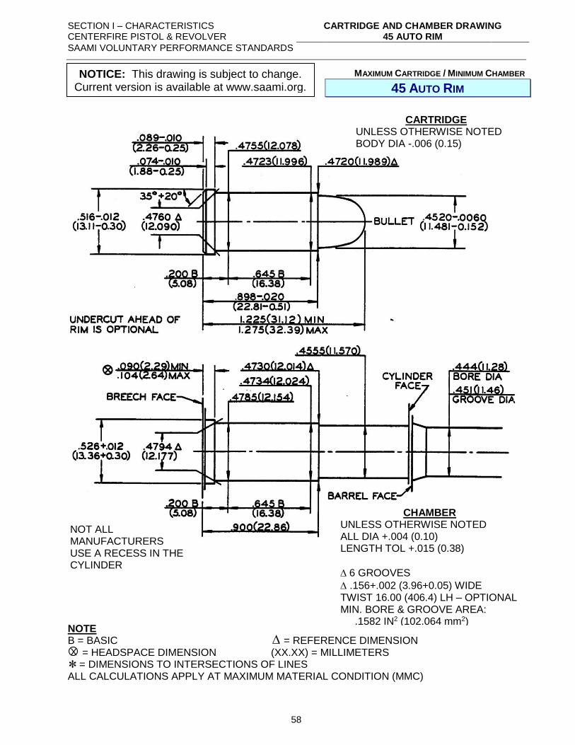
SECTION I – CHARACTERISTICS CENTERFIRE PISTOL & REVOLVER
CARTRIDGE AND CHAMBER DRAWING 45 AUTO RIM
SAAMI VOLUNTARY PERFORMANCE STANDARDS
58
MAXIMUM CARTRIDGE / MINIMUM CHAMBER
45 AUTO RIM
NOTE B = BASIC = REFERENCE DIMENSION = HEADSPACE DIMENSION (XX.XX) = MILLIMETERS = DIMENSIONS TO INTERSECTIONS OF LINES ALL CALCULATIONS APPLY AT MAXIMUM MATERIAL CONDITION (MMC)
CARTRIDGE UNLESS OTHERWISE NOTED BODY DIA -.006 (0.15)
CHAMBER UNLESS OTHERWISE NOTED ALL DIA +.004 (0.10) LENGTH TOL +.015 (0.38)
6 GROOVES
.156+.002 (3.96+0.05) WIDE TWIST 16.00 (406.4) LH – OPTIONAL MIN. BORE & GROOVE AREA: .1582 IN2 (102.064 mm2)
NOT ALL MANUFACTURERS USE A RECESS IN THE CYLINDER
X
NOTICE: This drawing is subject to change. Current version is available at www.saami.org.
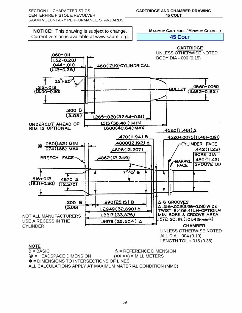
SECTION I – CHARACTERISTICS CENTERFIRE PISTOL & REVOLVER
CARTRIDGE AND CHAMBER DRAWING 45 COLT
SAAMI VOLUNTARY PERFORMANCE STANDARDS
59
MAXIMUM CARTRIDGE / MINIMUM CHAMBER
45 COLT
NOTE B = BASIC = REFERENCE DIMENSION = HEADSPACE DIMENSION (XX.XX) = MILLIMETERS = DIMENSIONS TO INTERSECTIONS OF LINES ALL CALCULATIONS APPLY AT MAXIMUM MATERIAL CONDITION (MMC)
CARTRIDGE UNLESS OTHERWISE NOTED BODY DIA -.006 (0.15)
NOT ALL MANUFACTURERS USE A RECESS IN THE CYLINDER CHAMBER
UNLESS OTHERWISE NOTED ALL DIA +.004 (0.10) LENGTH TOL +.015 (0.38)
X
NOTICE: This drawing is subject to change. Current version is available at www.saami.org.
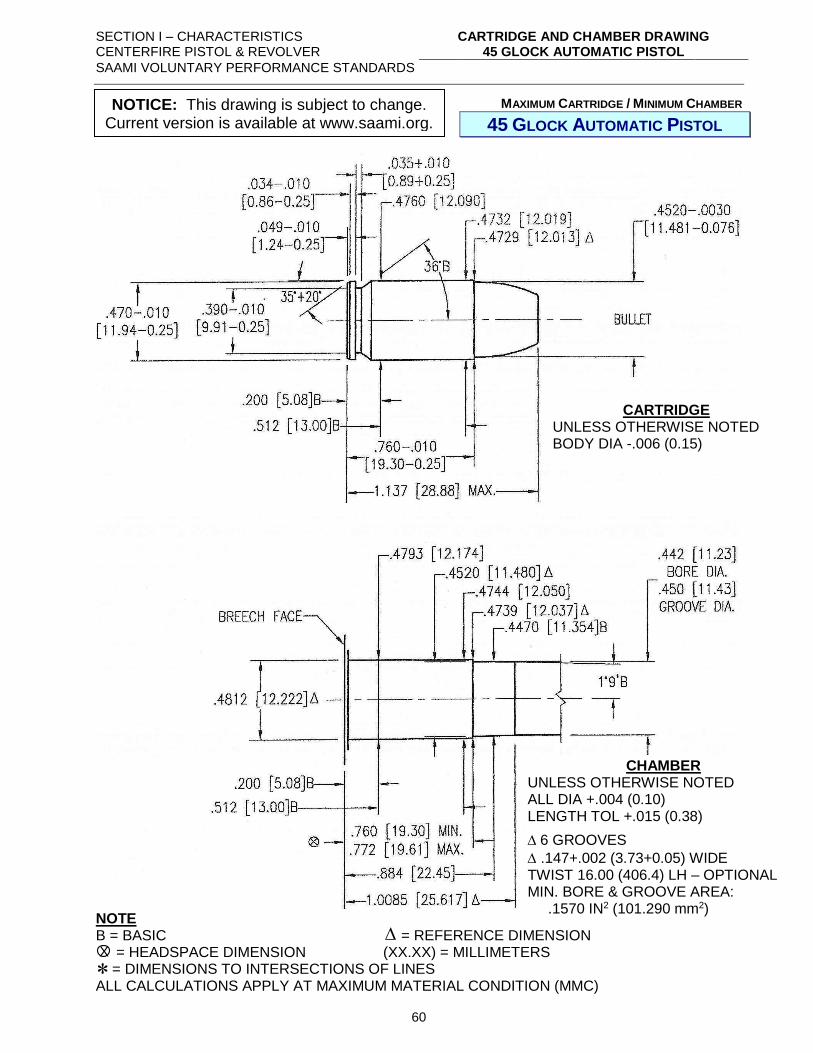
SECTION I – CHARACTERISTICS CENTERFIRE PISTOL & REVOLVER
CARTRIDGE AND CHAMBER DRAWING 45 GLOCK AUTOMATIC PISTOL
SAAMI VOLUNTARY PERFORMANCE STANDARDS
60
MAXIMUM CARTRIDGE / MINIMUM CHAMBER
45 GLOCK AUTOMATIC PISTOL
NOTE B = BASIC = REFERENCE DIMENSION = HEADSPACE DIMENSION (XX.XX) = MILLIMETERS = DIMENSIONS TO INTERSECTIONS OF LINES ALL CALCULATIONS APPLY AT MAXIMUM MATERIAL CONDITION (MMC)
CARTRIDGE UNLESS OTHERWISE NOTED BODY DIA -.006 (0.15)
CHAMBER UNLESS OTHERWISE NOTED ALL DIA +.004 (0.10) LENGTH TOL +.015 (0.38)
6 GROOVES
.147+.002 (3.73+0.05) WIDE TWIST 16.00 (406.4) LH – OPTIONAL MIN. BORE & GROOVE AREA: .1570 IN2 (101.290 mm2)
X
NOTICE: This drawing is subject to change. Current version is available at www.saami.org.
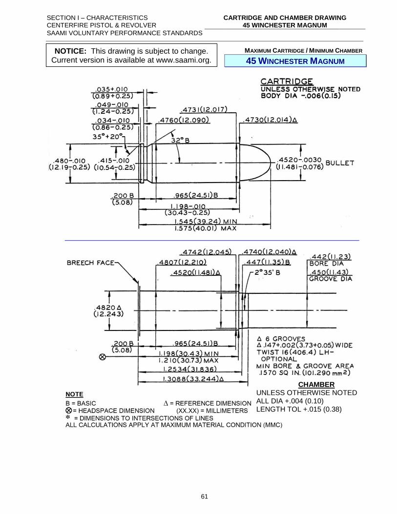
SECTION I – CHARACTERISTICS CENTERFIRE PISTOL & REVOLVER
CARTRIDGE AND CHAMBER DRAWING 45 WINCHESTER MAGNUM
SAAMI VOLUNTARY PERFORMANCE STANDARDS
61
MAXIMUM CARTRIDGE / MINIMUM CHAMBER
45 WINCHESTER MAGNUM
CHAMBER UNLESS OTHERWISE NOTED ALL DIA +.004 (0.10) LENGTH TOL +.015 (0.38)
NOTICE: This drawing is subject to change. Current version is available at www.saami.org.
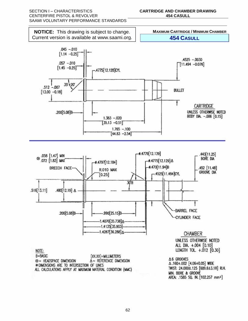
SECTION I – CHARACTERISTICS CENTERFIRE PISTOL & REVOLVER
CARTRIDGE AND CHAMBER DRAWING 454 CASULL
SAAMI VOLUNTARY PERFORMANCE STANDARDS
62
MAXIMUM CARTRIDGE / MINIMUM CHAMBER
454 CASULL
NOTICE: This drawing is subject to change. Current version is available at www.saami.org.
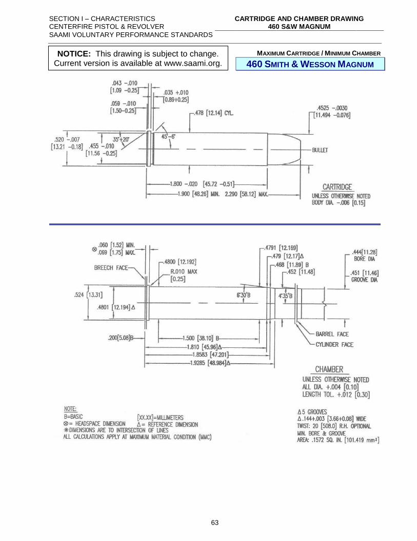
SECTION I – CHARACTERISTICS CENTERFIRE PISTOL & REVOLVER
CARTRIDGE AND CHAMBER DRAWING 460 S&W MAGNUM
SAAMI VOLUNTARY PERFORMANCE STANDARDS
63
MAXIMUM CARTRIDGE / MINIMUM CHAMBER
460 SMITH & WESSON MAGNUM
NOTICE: This drawing is subject to change. Current version is available at www.saami.org.
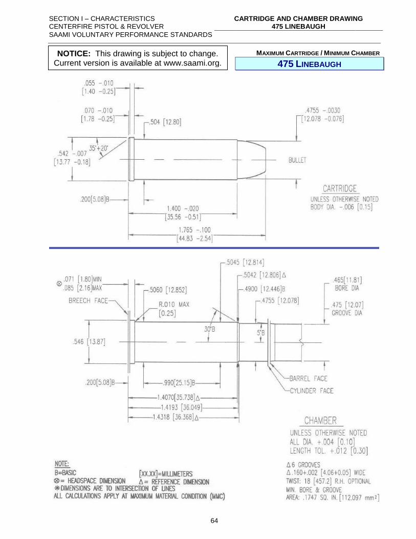
SECTION I – CHARACTERISTICS CENTERFIRE PISTOL & REVOLVER
CARTRIDGE AND CHAMBER DRAWING 475 LINEBAUGH
SAAMI VOLUNTARY PERFORMANCE STANDARDS
64
MAXIMUM CARTRIDGE / MINIMUM CHAMBER
475 LINEBAUGH
NOTICE: This drawing is subject to change. Current version is available at www.saami.org.
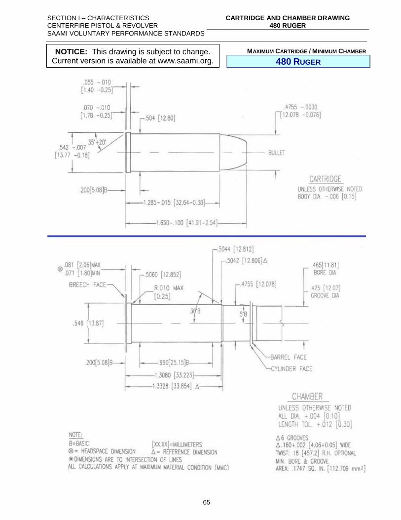
SECTION I – CHARACTERISTICS CENTERFIRE PISTOL & REVOLVER
CARTRIDGE AND CHAMBER DRAWING 480 RUGER
SAAMI VOLUNTARY PERFORMANCE STANDARDS
65
MAXIMUM CARTRIDGE / MINIMUM CHAMBER
480 RUGER
NOTICE: This drawing is subject to change. Current version is available at www.saami.org.
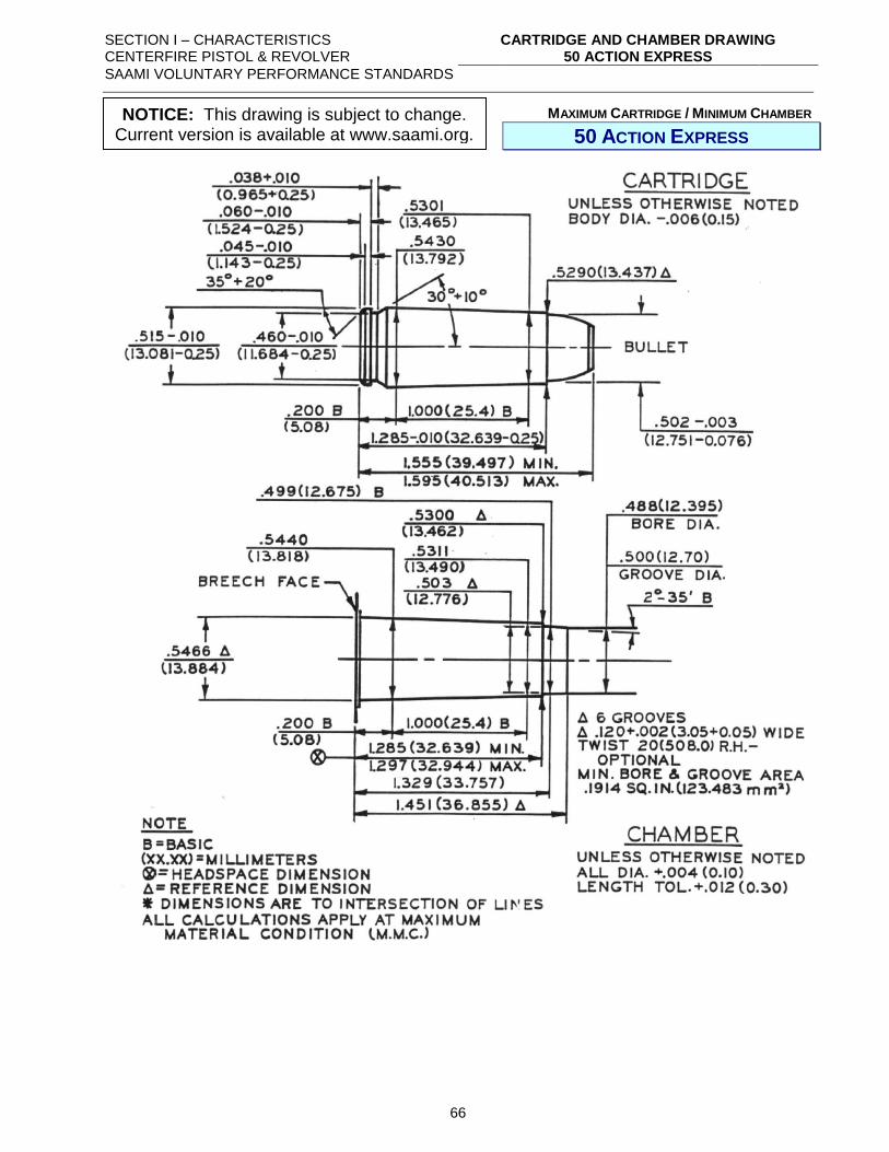
SECTION I – CHARACTERISTICS CENTERFIRE PISTOL & REVOLVER
CARTRIDGE AND CHAMBER DRAWING 50 ACTION EXPRESS
SAAMI VOLUNTARY PERFORMANCE STANDARDS
66
MAXIMUM CARTRIDGE / MINIMUM CHAMBER
50 ACTION EXPRESS
NOTICE: This drawing is subject to change. Current version is available at www.saami.org.
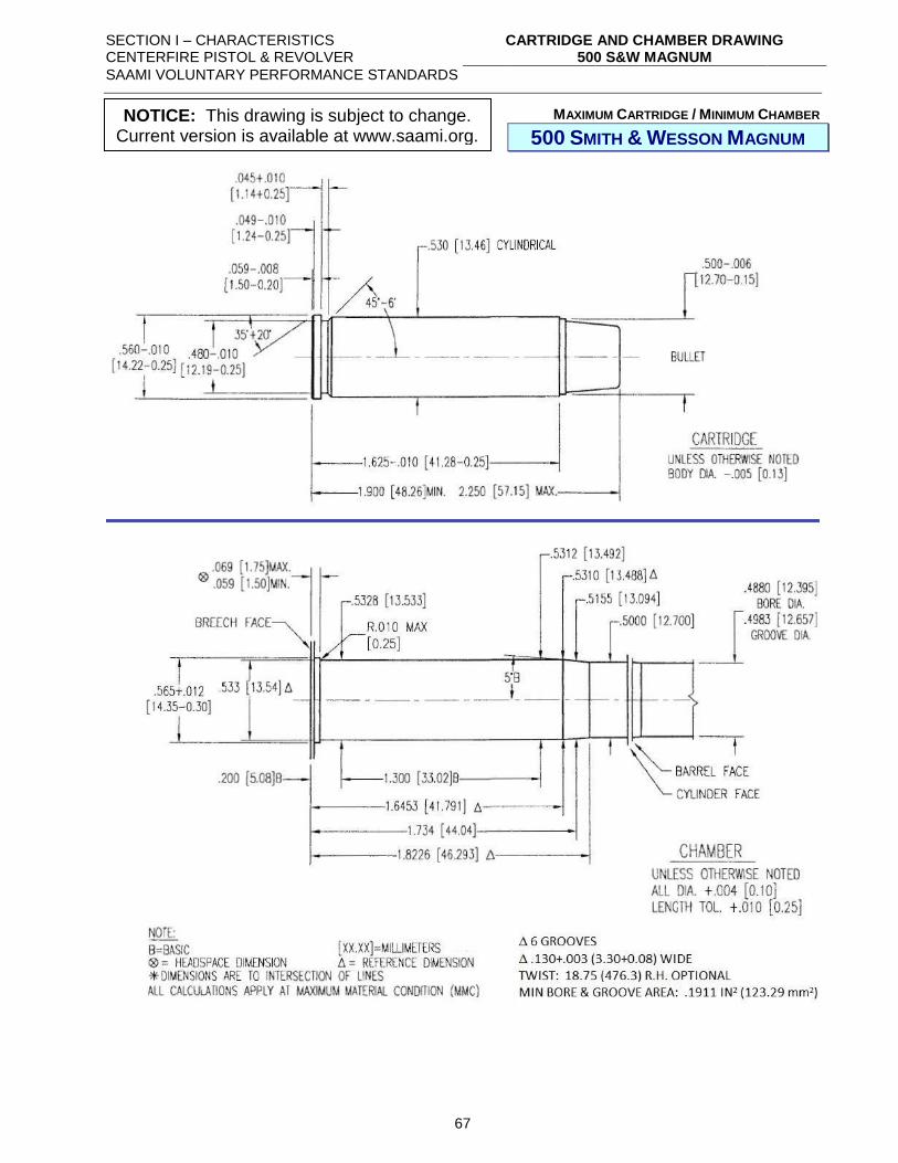
SECTION I – CHARACTERISTICS CENTERFIRE PISTOL & REVOLVER
CARTRIDGE AND CHAMBER DRAWING 500 S&W MAGNUM
SAAMI VOLUNTARY PERFORMANCE STANDARDS
67
MAXIMUM CARTRIDGE / MINIMUM CHAMBER
500 SMITH & WESSON MAGNUM
NOTICE: This drawing is subject to change. Current version is available at www.saami.org.
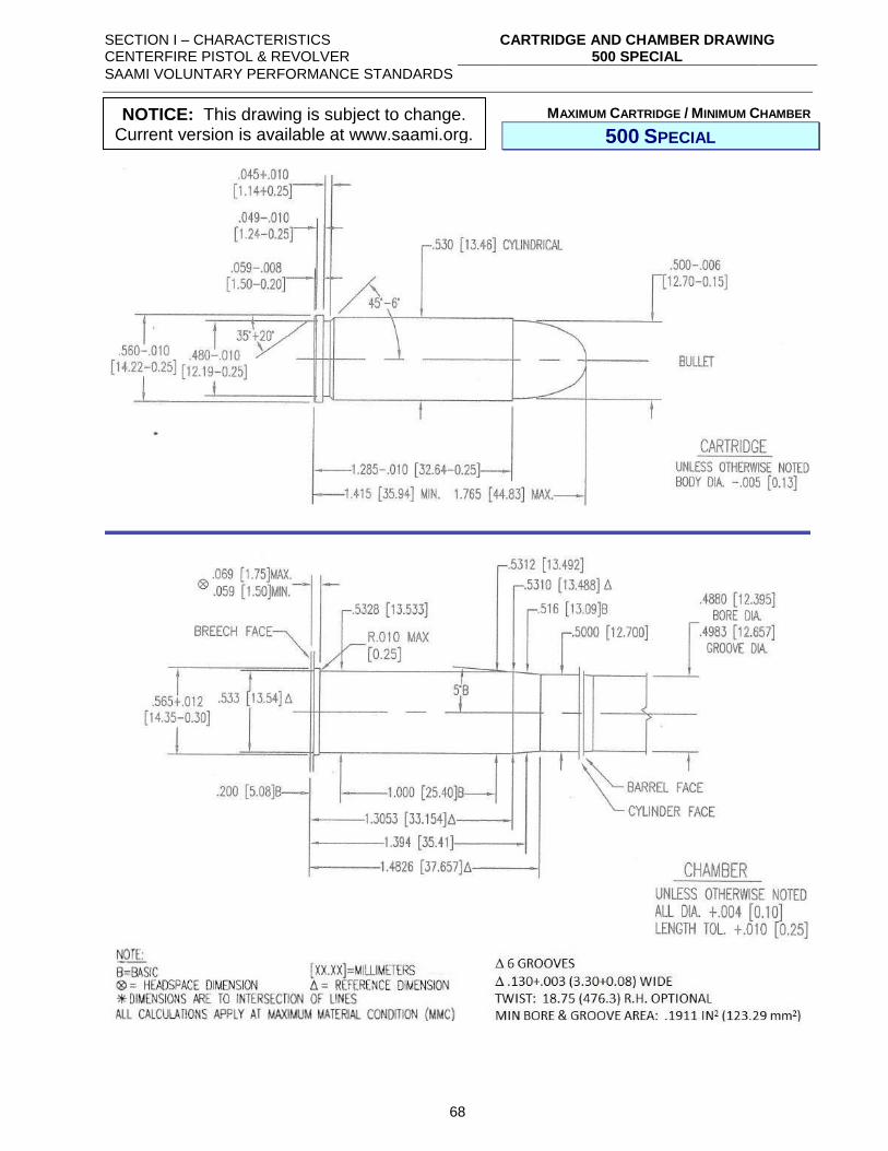
SECTION I – CHARACTERISTICS CENTERFIRE PISTOL & REVOLVER
CARTRIDGE AND CHAMBER DRAWING 500 SPECIAL
SAAMI VOLUNTARY PERFORMANCE STANDARDS
68
MAXIMUM CARTRIDGE / MINIMUM CHAMBER
500 SPECIAL
NOTICE: This drawing is subject to change. Current version is available at www.saami.org.
SECTION I – CHARACTERISTICS CENTERFIRE PISTOL & REVOLVER
MISCELLANEOUS: FRANGIBILITY
SAAMI VOLUNTARY PERFORMANCE STANDARDS
69
MISCELLANEOUS:
FRANGIBILITY
To be considered “frangible” against AR500 steel targets for the purposes of law enforcement
training, ammunition for centerfire pistol and revolver shall not produce any individual fragments
weighing more than 5% of the nominal bullet weight when tested as follows:
(1) A sample size of ten (10) rounds shall be fired.
(2) The distance from the muzzle to the impact point shall be 10.0’ ± 1.0’ (3.0 m ± 0.3
m).
(3) A minimum of 85% of the total nominal weight of the bullets fired shall be recovered.
(4) Testing is in accordance with the procedures detailed in Section II and equipment as
shown in Section III.
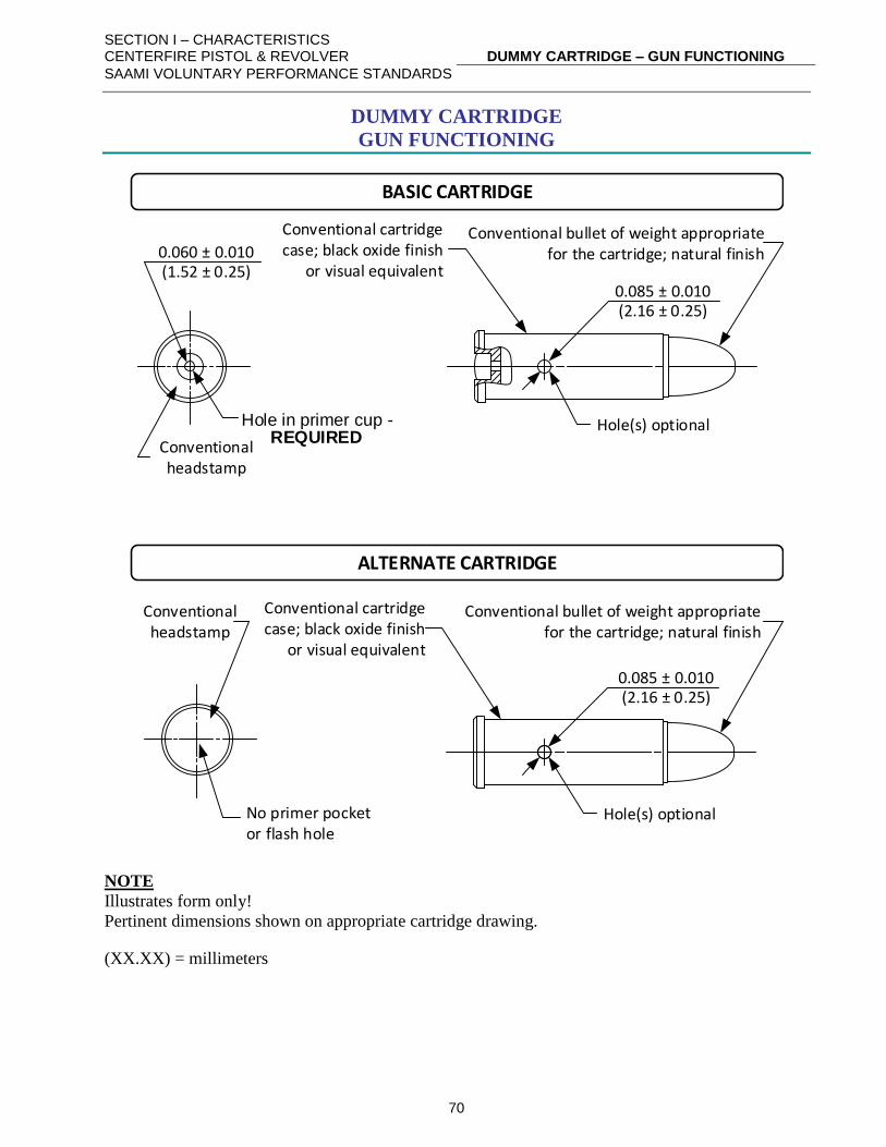
SECTION I – CHARACTERISTICS CENTERFIRE PISTOL & REVOLVER
DUMMY CARTRIDGE – GUN FUNCTIONING
SAAMI VOLUNTARY PERFORMANCE STANDARDS
70
DUMMY CARTRIDGE
GUN FUNCTIONING
Conventional cartridge case; black oxide finish
or visual equivalent0.060 ± 0.010(1.52 ± 0.25)
Hole in primer cup - REQUIRED
Conventional headstamp
Conventional bullet of weight appropriate for the cartridge; natural finish
0.085 ± 0.010(2.16 ± 0.25)
Hole(s) optional
No primer pocket or flash hole
BASIC CARTRIDGE
ALTERNATE CARTRIDGE
Conventional headstamp
Conventional cartridge case; black oxide finish
or visual equivalent
Conventional bullet of weight appropriate for the cartridge; natural finish
Hole(s) optional
0.085 ± 0.010(2.16 ± 0.25)
NOTE
Illustrates form only!
Pertinent dimensions shown on appropriate cartridge drawing.
(XX.XX) = millimeters
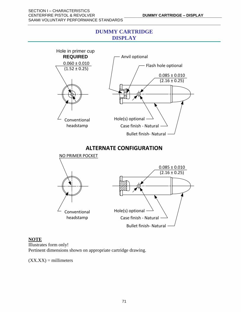
SECTION I – CHARACTERISTICS CENTERFIRE PISTOL & REVOLVER
DUMMY CARTRIDGE – DISPLAY
SAAMI VOLUNTARY PERFORMANCE STANDARDS
71
DUMMY CARTRIDGE
DISPLAY
Case finish - Natural
0.060 ± 0.010(1.52 ± 0.25)
Conventional headstamp
Bullet finish- Natural
0.085 ± 0.010(2.16 ± 0.25)
Hole(s) optional
Hole in primer cup
REQUIRED Anvil optional
Flash hole optional
Case finish - Natural
NO PRIMER POCKET
Conventional headstamp
Bullet finish- Natural
0.085 ± 0.010(2.16 ± 0.25)
Hole(s) optional
ALTERNATE CONFIGURATION
NOTE
Illustrates form only!
Pertinent dimensions shown on appropriate cartridge drawing.
(XX.XX) = millimeters
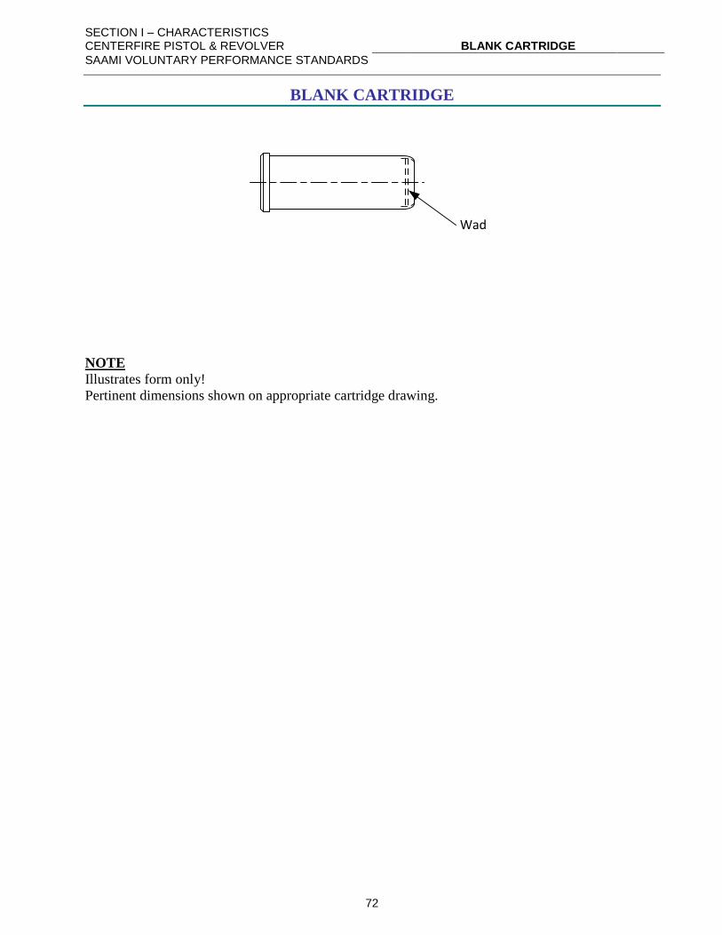
SECTION I – CHARACTERISTICS CENTERFIRE PISTOL & REVOLVER
BLANK CARTRIDGE
SAAMI VOLUNTARY PERFORMANCE STANDARDS
72
BLANK CARTRIDGE
Wad
NOTE
Illustrates form only!
Pertinent dimensions shown on appropriate cartridge drawing.
SECTION I – CHARACTERISTICS CENTERFIRE PISTOL & REVOLVER
TOLERANCE – BULLET WEIGHT
SAAMI VOLUNTARY PERFORMANCE STANDARDS
73
TOLERANCE – BULLET WEIGHT
1. Lead and lead-core bullets:
Less than 100 grains.............................. Nominal weight ± 2.0%
Equal to or greater than 100 grains ....... Nominal weight ± 1.5%
2. Bullets of principally non-lead construction:
All bullet weights .................................. Nominal weight ± 3.0%
SECTION II – PROCEDURES CENTERFIRE PISTOL & REVOLVER
PROCEDURE: VELOCITY & PRESSURE TESTING
SAAMI VOLUNTARY PERFORMANCE STANDARDS
74
PROCEDURE:
VELOCITY & PRESSURE TESTING
I. SCOPE
A. This procedure covers the testing of ammunition for assessment of velocity and pressure
using either the copper crusher method of pressure measurement or with piezoelectric
pressure transducers (“transducers”).
II. GENERAL
A. When testing using copper crushers, velocities and pressures are measured simultaneously
using test barrels fitted with short pistons and gas checks.
B. When testing using transducers, velocities and pressures are measured simultaneously.
C. Recommended values for velocity and pressure of all centerfire pistol and revolver cartridges
are tabulated in Section I. When required, a retest of double the original quantity may be
fired with statistically equivalent tolerances.
D. Velocities and pressures should be measured using horizontally-mounted test barrels in
accordance with the drawings and descriptions listed in Section III.
III. EQUIPMENT
A. COMMON
Item Type Alternate
1. Universal receiver “Frankford Arsenal” or equivalent
2. Photoelectric screens Oehler Model 55 or 57 or equivalent
3. Ballistic measurement system Oehler Model 85 or equivalent
B. COPPER CRUSHER TESTING
Item Type Alternate
1. Test barrel Piston type - - -
2. Pistons Short - - -
3. Gas Checks 0.206”, waxed or unfilled - - -
4. Copper crushers .146” x .400” or .225” x .400” as needed - - -
5. Micrometer Capable of measuring to 0.0005” - - -
6. Tarage table Specific for lot of crushers in use - - -
C. TRANSDUCER TESTING
Item Type Alternate
1. Charge Amplifier PCB, Model 443B02 or equivalent
2. Voltmeter, Peak Capture PCB, Model 444A152 or equivalent
3. Transducer PCB, Model 117BXXX or equivalent
4. Low Noise Cable PCB, Model 003CXX or equivalent
5. Integrated Data Oehler Research, Inc., or equivalent
Acquisition System System 85
SECTION II – PROCEDURES CENTERFIRE PISTOL & REVOLVER
PROCEDURE: VELOCITY & PRESSURE TESTING
SAAMI VOLUNTARY PERFORMANCE STANDARDS
75
IV. HANDLING OF AMMUNITION
A. Cartridges to be tested should be placed in a vertical position with primer-end down in a
recessed holding block.
B. When the appropriate test barrel has been properly serviced and the chronograph reset, a
cartridge should be lifted vertically from the block. It should be rotated slowly, end over
end, in a vertical plane through 360° pausing momentarily when the powder is at the bullet
end and again when the powder is at the primer end.
C. The cartridge is then rotated slowly, a minimum amount to enter the chamber, keeping the
primer end in the lowest possible position until inserted gently and carefully into the
chamber.
D. The cartridge should be seated in the chamber as far as practicable with the fingers. The bolt
or breech mechanism should be closed gently in order not to disturb the position of the
powder in the cartridge case. The object of this method of handling cartridges is to position
the propellant powder at the primer end of the cartridge case by permitting it to fall gently
against the primer while rotating the case.
E. The rate of fire should not be rapid enough to cause excessive heating of the barrel. The time
between rounds depends on the equipment, as the barrel may be cooled by a constant stream
of air on the outside or by directing air through the bore after each ten rounds.
F. Ammunition conditioning should be between 60° - 80°F (15.6° - 26.7°C).
G. A minimum of one and up to three warming shots should be fired before firing each series
for record. The velocity and/or pressure of these shots may be recorded, but should not be
included in the record of the sample.
V. PRESSURE DETERMINATION
A. COPPER CRUSHER TESTING
1. Insert wax-filled gas check in piston hole with open end toward chamber and seat to
approximately one-half the depth of the piston hole with seating tool. (Exceptions: 357
Magnum, 41 Remington Magnum – unfilled gas checks may be used.)
2. Dip piston shank in oil and drain until but one drop of oil remains. Scrape the remaining
drop from the bottom of the piston or blot remaining oil on a flannel patch.
3. Insert piston in piston hole and seat on gas check manually. Do not force by striking or
hammering.
CAUTION: The piston must be checked to make sure it slides freely,
but not loosely, in the piston hole at all times. If the piston does not
slide freely, it should be withdrawn from the piston hole and
examined. Any black deposits should be removed with worn crocus
cloth. If the piston is still not free in the piston hole, the
hole should be cleaned with worn crocus cloth.
4. Insert cartridge to be tested in chamber of standard velocity and pressure test barrel in the
manner described in paragraphs IV(B) through IV(D), above.
5. Using finger pressure, push the piston down into the piston hole until the piston/gas
check is fully seated.
6. Center crusher cylinder appropriate for the cartridge under test upon the head of the
piston. Slide the anvil bridge so as to center it over the crusher/piston and securely
SECTION II – PROCEDURES CENTERFIRE PISTOL & REVOLVER
PROCEDURE: VELOCITY & PRESSURE TESTING
SAAMI VOLUNTARY PERFORMANCE STANDARDS
76
tighten the set screws on the bridge. Gently tighten the anvil against the crusher cylinder
using light finger pressure.
CAUTION: Overtightening the anvil can cause precompression of
the crusher cylinder and affect the subsequent pressure reading. Use
care to not over-tighten the anvil.
CAUTION: The face of the piston head, face of set screw and faces
of crusher must be free from oil.
7. The breech mechanism should be closed gently.
8. After firing the cartridge, the compressed crusher cylinder should be removed and
measured for remaining length. Pressure is determined from this length by the use of the
Tarage Table, furnished with the cylinders, for the piston diameter used.
9. Wax-filled gas checks should be changed after firing each series of two warming shots
and ten rounds for record. Unfilled gas checks should be removed after each shot by
driving the gas check downward with the knockout tool.
10. The fired cartridge case containing the gas check and disk blanked from the cartridge
case is removed from the chamber.
11. Gas checks knocked into the bore should be ejected from the muzzle by the introduction
of compressed air directed through the chamber.
CAUTION: The chamber and bore should be checked to make
certain that the barrel is unobstructed before proceeding further.
12. For subsequent shots in a series, the procedure shown in paragraphs V(A)(1) through
V(A)(11) is repeated.
B. PIEZO-ELECTRIC TRANSDUCER TESTING
1. EQUIPMENT PREPARATION
1.1 Refer to the SAAMI-recommended piezo pressure transducer installation in a
pressure barrel illustrated in Section III.
1.2 The charge amplifier and peak capture voltmeter should have a certified calibration
traceable to the National Institute of Standards and Technology.
2. INITIAL SET-UP
SECTION II – PROCEDURES CENTERFIRE PISTOL & REVOLVER
PROCEDURE: VELOCITY & PRESSURE TESTING
SAAMI VOLUNTARY PERFORMANCE STANDARDS
77
2.1 Turn on the electronic equipment and allow to stabilize as recommended by the
manufacturer.
2.2 Inspect the transducer mounting cavity in the pressure barrel to assure that the seal
seat is free of dirt and any other foreign matter.
2.3 Mount transducer with steel spacer rings into the test barrel as described in PCB
Operating Instructions Manual.
2.4 Loosen, but do not remove, the slotted clamp.
2.5 Thread the transducer into the mounting port. Adjust the slotted clamp to allow
guide pin to enter guide hole. Continue to turn transducer nut into the mounting
port. When transducer bottoms, tighten the slotted clamp and torque the transducer
as recommended by the manufacturer.
2.6 It is essential that the sensing surface of the transducer be flush with the chamber
inside diameter. Care must be exercised to obtain correct depth as well as exact
rotational alignment. Depth adjustment is accomplished by the use of various
thickness spacers. In order to set the depth exactly it may be necessary to hone the
spacers to the desired thickness.
2.7 Connect equipment as shown in Figure 5 or Figure 6, page 91-92.
a. NOTE: Configurations 1 and 2 are interchangeable.
IMPORTANT: Always switch the amplifier to the “zero lock” mode by pressing
the “ZERO” button before making connections to the Model 443B02, and allow
switch to remain in this position during such connections. This protects the FET
input stage against possible gate damage from excessive accumulated static charge.
2.8 Set the charge amplifier controls for 0.2 Hz short time constant, transducer
sensitivity to the slope (m) obtained from the transducer least square line equation,
output sensitivity to 0.100 mV/unit, and set the amplifier to operating mode
(releasing the “zero lock” by pressing the “ZERO” button a second time).
2.9 Select digital peak meter, positive input, peak mode, and 10-volt range.
2.10 Take note of the transducer offset value (P) obtained from the least square line
equation. This value will be used later in making final peak pressure determination.
(a) The offset value may also be dialed into an instrumentation system capable of
providing direct peak pressures without data manipulation.
3. PROCEDURE
3.1 Reset all pressure instrumentation and assure that the peak meter digital display
reads all zeros. Test rounds may now be fired.
3.2 For each round fired, the pressure reading on the digital display should be recorded
and pressure instrumentation reset.
4. PEAK PRESSURE DETERMINATION
4.1 To determine peak pressures, add as required, the pressure offset value to the
pressure readings obtained in the firing test. Adding the offset value is not required
if it is dialed in on the peak meter.
VI. VELOCITY DETERMINATION
SECTION II – PROCEDURES CENTERFIRE PISTOL & REVOLVER
PROCEDURE: VELOCITY & PRESSURE TESTING
SAAMI VOLUNTARY PERFORMANCE STANDARDS
78
A. Handling of the ammunition should be in accordance with the instructions in paragraph IV.
B. Photoelectric screens should be arranged in accordance with the arrangement shown in
Section III, page 131, “Equipment: Schematic Layout of Velocity Screens”.
C. A table of time of flight vs. velocity should be used to determine instrumental velocity at 15
feet (4.57 m), nominal, from the gun muzzle (not required when using direct reading
equipment).
D. It is recommended that a blast shield be positioned between the muzzle of the Universal
Receiver test barrel and the first velocity screen to minimize possibility of premature
triggering of the velocity screens. With velocities below the speed of sound, the muzzle blast
and/or muzzle flash will reach the screen before the bullet and may cause premature
triggering of the screen. For example, premature triggering of the first screen will result in
abnormally low velocity readings. Premature triggering of both screens will result in
velocity readings which correspond to the speed of sound (approximately 1,120 fps at sea
level and normal atmospheric conditions).
(i) The blast shield should be made of rigid, opaque material of sufficient
strength to withstand the shock wave but not be resistant to the passage of the
projectile.
VII. RECORDING OF TEST RESULTS
A. The following data should be recorded for each series of shots fired for velocity and pressure.
1. Ammunition Data
1.1 Date of test
1.2 Nominal cartridge identification
1.3 Cartridge caliber
1.4 Bullet weight and type
1.5 Powder charge, type, and lot
1.6 Priming
1.7 Type of lubricant (if any)
1.8 Code or date of loading
2. Average velocity, uncorrected.
3. Average pressure, uncorrected.
4. Maximum and minimum individual velocity.
5. Maximum and minimum individual pressure.
6. Extreme variation (range) of velocity.
7. Extreme variation (range) of pressure.
8. Other statistical indication of variation (optional).
9. Correction to results from firing Reference Ammunition (optional).
10. Corrected average velocity (optional).
11. Corrected average pressure (optional).
12. Recommended values
12.1 Average velocity
12.2 Average pressure
12.3 Velocity and pressure variation
13. Test firearm and range data
SECTION II – PROCEDURES CENTERFIRE PISTOL & REVOLVER
PROCEDURE: VELOCITY & PRESSURE TESTING
SAAMI VOLUNTARY PERFORMANCE STANDARDS
79
13.1 Barrel length and serial number
13.2 Barrel history
13.3 Transducer serial number / copper crusher lot number
13.4 Type of chronograph and screens
14. Test personnel.
VIII. USE OF REFERENCE AMMUNITION
A. Purpose
1. Reference ammunition, assessed by firings at the ranges of member companies, is
available for calibrating ranges, firearms and other equipment for velocity and pressure
only.
B. Supply
1. On request, the SAAMI Technical Office1 will supply information on the manufacturer of
specific Reference Ammunition. The method of identifying Reference Ammunition is
shown in Section II.
2. Requests for Reference Ammunition should be addressed to the manufacturer of the
specific cartridge.
C. Assessment
1. Details of the assessment tests are shown in Section II.
D. Clearing House
1. Results of assessment tests of Reference Ammunition are tabulated, analyzed and
distributed by the SAAMI Technical Office.
E. Corrections
1. For method of applying corrections to tests of service loads see Section II.
F. Calibration
1. For method of calibrating ranges and equipment, see Section II.
IX. TEST BARREL CLEANING
A. Test barrels should be cleaned regularly using solvents, brushes and/or other equipment as
dictated by the type and severity of fouling in the test barrel.
1 Refer to Section III, Page 130, for contact information for the SAAMI Technical Office.
SECTION II – PROCEDURES CENTERFIRE PISTOL & REVOLVER
VELOCITY & PRESSURE BARRELS: QUALIFICATION
SAAMI VOLUNTARY PERFORMANCE STANDARDS
80
VELOCITY & PRESSURE BARRELS:
QUALIFICATION
All barrels are not necessarily suitable for use in determining pressure or velocity levels, even
though they may conform to the dimensions given on the appropriate Standard Velocity and Pressure
Barrel drawing in this Standard. New barrels may require a number of rounds to be fired to remove
sharp corners or burrs resulting from the manufacturing process. Barrels in service do not have an
unlimited life and may become unserviceable from wear and erosion. There is no predictable
number of rounds to which a barrel should be exposed before use for pressure and velocity
determinations, nor is there a predictable round life for such equipment.
The following procedure is suggested for determining the suitability of any barrel for pressure and
velocity test use:
Fire ten rounds of SAAMI Reference Ammunition following the procedures as shown
in this Standard. The average velocity and pressure results of the test should be
within the Inclusion Limits as given on the latest assessment of the lot fired.
In the case of a new barrel, the firing of more breaking-in shots may be indicated after which the
Reference Ammunition test should be repeated.
In the case of barrels which have been in service, refurbishing of the piston and piston hole, removal
of fouling, or other corrective procedures may be implemented followed by a retest.
SECTION II – PROCEDURES CENTERFIRE PISTOL & REVOLVER
VELOCITY & PRESSURE BARRELS: MOUNTING IN RECEIVERS
SAAMI VOLUNTARY PERFORMANCE STANDARDS
81
VELOCITY & PRESSURE BARRELS:
MOUNTING IN RECEIVERS
It is essential that close headspace be maintained in velocity-pressure testing equipment if reliable
test results are to be achieved.
In mounting test barrels to Universal Receivers or test actions, a headspace not exceeding 0.003”
(0.07 mm) over minimum should be maintained. This may be measured by headspace gauges, shim
stock or feeler gauges, or a combination thereof whichever is most appropriate for the type of
equipment being used.
Headspace adjustments with the Universal Receiver may be accomplished by several methods:
1. Formed shim stock behind the firing-pin plate.
2. Formed shim stock on the rear bearing shoulder of the Barrel Collar.
3. Adjustment of the Breech Block Locking Screws.
SECTION II – PROCEDURES CENTERFIRE PISTOL & REVOLVER
PROCEDURE: USE OF PISTON HOLE GAUGES
SAAMI VOLUNTARY PERFORMANCE STANDARDS
82
PROCEDURE:
USE OF PISTON HOLE GAUGES
Pressure barrel piston hole size should be checked periodically with piston hole gauges to determine
whether or not erosion is present. Piston hole erosion can cause high or erratic pressure readings and
low velocity readings.
Three piston hole gauges for each piston hole size (0.146” diameter, 0.206” diameter) constitute a
set: 1) plug gauge, 2) longitudinal gauge and, 3) transverse gauge. Each gauge is double-sided,
“go” and “no go”. The gauges are used as described below:
1. Attempt to insert the appropriate “no go” plug gauge into the top of the piston hole.
2. Insert the appropriate “no go” longitudinal gauge through the chamber, align it with the
bottom of the piston hole, and attempt to insert the gauge upward into the hole.
3. Attempt to insert the appropriate “no go” transverse gauge into the bottom of the piston
hole in the same manner as described above for the longitudinal gauge.
4. If the piston hole accepts any of the “no go” gauges, the hole diameter is larger than the
maximum acceptable.
The probable cause of extreme piston hole erosion is poor gas sealing (improper use of gas checks
and/or insufficient oiling).
In some cases, minor erosion does not seem to affect pressure and velocity readings. An analysis of
test results will indicate whether or not repair is necessary.
SECTION II – PROCEDURES CENTERFIRE PISTOL & REVOLVER
PROCEDURE: PIEZOELECTRIC TRANSDUCER CALIBRATION
SAAMI VOLUNTARY PERFORMANCE STANDARDS
83
PROCEDURE:
PIEZOELECTRIC TRANSDUCER CALIBRATION
I. SCOPE
A. This procedure covers the calibration of piezoelectric pressure transducers (“transducers”) for
use in the measurement of ballistic pressures.
II. TEST EQUIPMENT
A. ITEM TYPE ALTERNATE
1. Digital Voltmeter Fluke, Model 8440 or equivalent
2. Charge Amplifier PCB, Model 443B02 or equivalent
3. Transducer Calibrator PCB Group; The Modal or equivalent
(Direct fluidic calibrator) Shop, Inc.;
Model K9905D
4. Insulation Tester Kistler, Model 5491 or equivalent
5. Transducer PCB, Model 117BXXX or equivalent
6. Low Noise Cable PCB, Model 003CXX or equivalent
7. Calibration Adapter PCB, Model 090B Series or equivalent
III. EQUIPMENT PREPARATION
A. All instruments should be operational and calibrated per manufacturer specification.
B. The transducer calibrator and instruments used to calibrate the charge amplifier and digital
voltmeter should have a certified calibration traceable to the National Institute of Standards
and Technology.
C. Transducers should be properly maintained per manufacturer recommendations or stored in a
desiccator when not in use.
CAUTION: When not in use, the cable, transducers, and instrument
connectors should be stored with plastic caps to prevent contamination.
D. Measure the internal resistance of the transducer and low noise cable. If the resistance is less
than 1012 ohms, follow the steps detailed in paragraph IV, Transducer Initialization. If the
resistance is in the 1012 to 1014 ohm range, proceed to paragraph V, Transducer Calibration.
IV. TRANSDUCER INITIALIZATION
A. Clean transducer and low noise cable connectors using an acceptable solvent per the
manufacturer’s recommendations.
B. Bake-out transducer and low noise cable in a temperature controlled oven for 24 to 48 hours
at 250°F (121°C).
C. Allow oven to return to ambient temperature at a slow rate.
D. After removing the transducer and cable from the oven, check the internal resistance of the
transducer. The resistance should be in the 1012 to 1014 ohm range.
E. Place protective caps on transducer and cable connectors to prevent contamination.
SECTION II – PROCEDURES CENTERFIRE PISTOL & REVOLVER
PROCEDURE: PIEZOELECTRIC TRANSDUCER CALIBRATION
SAAMI VOLUNTARY PERFORMANCE STANDARDS
84
V. TRANSDUCER CALIBRATION
A. INITIAL SET-UP
1. Turn on the electronic equipment and allow it to stabilize as recommended by the
manufacturer.
2. Inspect the transducer mounting cavity to assure that the seal seat is free of dirt and any
other foreign matter.
3. Mount transducer with steel spacer rings into calibration fixture as described in PCB
Operating Instructions Manual.
4. Loosen, but do not remove, the slotted clamp.
5. Thread the transducer into the mounting port. Adjust the slotted clamp to allow guide
pin to enter guide hole. Continue to turn transducer nut into the mounting port. When
transducer bottoms, tighten the slotted clamp and torque the transducer as recommended
by the manufacturer.
6. It is essential that the sensing surface of the transducer be flush with the chamber inside
diameter. Care must be exercised to obtain correct depth as well as exact rotational
alignment. Depth adjustment is accomplished by the use of various thickness spacers.
In order to set the depth exactly it may be necessary to hone the spacers to the desired
thickness.
7. Mount calibration adapter with transducer on the calibrator.
8. Insert the cartridge case with an inert or fired primer into calibration adapter and
complete fixture assembly as per PCB instruction manual. If the sample cartridge is a
loaded round, it may be disassembled, the powder removed, and the primer in the empty
case then fired. An optional procedure is to deprime the case and use the O-ring/plug
seal shown in Section III - page 135. Cycle this case to the appropriate maximum
pressure in order to “seat” the transducer.
9. Connect transducer and instrumentation as indicated in Figure 2 on page 88.
10. Set the charge amplifier sensitivity to 0.999 and set the time constant switch to LONG.
11. Set DVM to 10-volt range.
B. CALIBRATION
1. Adjust pressure readout indicator of the transducer calibrator to 0 psi with no pressure
on hydraulic lines.
2. Insert a new cartridge case.
3. Reset charge amplifier and digital voltmeter (DVM) to obtain zero volts output.
4. Apply pressure in increments as indicated in Section II, pages 86-87. Calibration
pressure range should cover the pressure ranges shown in Section II, pages 86-87. DO
NOT exceed the maximum pressure established by the manufacturer for the fixture.
5. Record DVM reading after the pressure readout indicator is exactly at desired pressure
level. Do not release the pressure until the highest pressure level, for the cartridge under
test, has been reached. Read the pressure at each increment. Do not overshoot the
pressure points!
6. After reaching the highest calibration pressure level, release the pressure slowly.
7. Replace the cartridge case in calibration adapter.
8. Repeat steps 1 through 7 until a minimum of ten valid data points are obtained.
SECTION II – PROCEDURES CENTERFIRE PISTOL & REVOLVER
PROCEDURE: PIEZOELECTRIC TRANSDUCER CALIBRATION
SAAMI VOLUNTARY PERFORMANCE STANDARDS
85
CAUTION: Always INCREASE pressure to desired level, never decrease pressure to
desired level.
9. Transducers need to be re-calibrated when changing brands of ammunition or if there
have been changes in cartridge case processes and/or material.
C. DATA REDUCTION
1. Calculate the average value for the output voltages recorded at each pressure increment.
Multiply these average values by the charge amplifier sensitivity (pC/V) to obtain the
transducer charge output (Q) at these pressure increments (P).
2. Obtain a least square line equation using the transducer charge output (Q) as the
dependent variable and pressure (P) as the independent variable. Q = mP ± q.
3. A manual method of calculating the least square line equation is given in tabular form on
page 89. It is recommended that when using this technique, all numbers be carried to
the third decimal place.
4. Obtain the pressure (P) offset value when Q in the line equation is zero. Refer to Figure
4, page 90.
VI. CALIBRATION CHECK
A. When the calibration calculations are complete, the sensitivity should be set on the charge
amplifier. The digital voltmeter is set at zero. A new sample cartridge case is put in the
calibration fixture and the hydraulic pressure increased to the highest pressure reached in the
calibration. The digital voltmeter reading plus the offset should equal the hydraulic gauge
reading. Check calibration again by inserting a second cartridge case. As a guideline, these
values should agree within ±1.5% of the gauge reading. If the transducer does not meet this
guideline then recheck the calculations and/or recalibrate.
VII. TRANSDUCER RECORDS
A. Date of calibration
B. The number of rounds to which the transducer has been exposed during test firing.
C. Calibration pressure (P), charge amplifier voltage output (V), and transducer charge output
(Q).
D. Charge amplifier sensitivity.
E. Least square line equation.
F. Pressure offset, and transducer sensitivity (slope = m).
G. Transducer identification.
H. Date of next calibration.
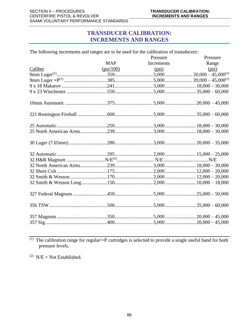
SECTION II – PROCEDURES CENTERFIRE PISTOL & REVOLVER
TRANSDUCER CALIBRATION: INCREMENTS AND RANGES
SAAMI VOLUNTARY PERFORMANCE STANDARDS
86
TRANSDUCER CALIBRATION:
INCREMENTS AND RANGES
The following increments and ranges are to be used for the calibration of transducers:
Pressure Pressure
MAP Increments Range
Caliber (psi/100) (psi) (psi)
9mm Luger(1) .........................................350............................... 5,000 ...................... 20,000 – 45,000(1)
9mm Luger +P(1) ...................................385............................... 5,000 ...................... 20,000 – 45,000(1)
9 x 18 Makarov .....................................241............................... 3,000 ......................... 18,000 – 30,000
9 x 23 Winchester .................................550............................... 5,000 ......................... 35,000 – 60,000
10mm Automatic ..................................375............................... 5,000 ......................... 20,000 – 45,000
221 Remington Fireball ........................600............................... 5,000 ......................... 35,000 – 60,000
25 Automatic .........................................250............................... 3,000 ......................... 18,000 – 30,000
25 North American Arms......................239............................... 3,000 ......................... 18,000 – 30,000
30 Luger (7.65mm) ...............................280............................... 3,000 ......................... 20,000 – 35,000
32 Automatic .........................................205............................... 2,000 ......................... 15,000 – 25,000
32 H&R Magnum ............................... N/E(2) .............................. N/E .................................... N/E
32 North American Arms......................239............................... 3,000 ......................... 18,000 – 30,000
32 Short Colt .........................................175............................... 2,000 ......................... 12,000 – 20,000
32 Smith & Wesson ..............................170............................... 2,000 ......................... 12,000 – 20,000
32 Smith & Wesson Long .....................150............................... 2,000 ......................... 10,000 – 18,000
327 Federal Magnum ............................450............................... 5,000 ......................... 25,000 – 50,000
356 TSW ...............................................500............................... 5,000 ......................... 35,000 – 60,000
357 Magnum .........................................350............................... 5,000 ......................... 20,000 – 45,000
357 Sig. .................................................400............................... 5,000 ......................... 20,000 – 45,000
(1) The calibration range for regular/+P cartridges is selected to provide a single useful band for both
pressure levels.
(2) N/E = Not Established.
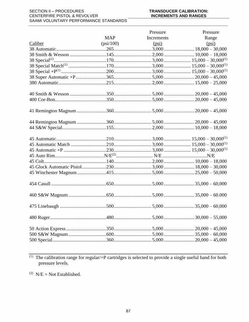
SECTION II – PROCEDURES CENTERFIRE PISTOL & REVOLVER
TRANSDUCER CALIBRATION: INCREMENTS AND RANGES
SAAMI VOLUNTARY PERFORMANCE STANDARDS
87
Pressure Pressure
MAP Increments Range
Caliber (psi/100) (psi) (psi)
38 Automatic .........................................265............................... 3,000 ......................... 18,000 – 30,000
38 Smith & Wesson ..............................145............................... 2,000 ......................... 10,000 – 18,000
38 Special(1) ...........................................170............................... 3,000 ...................... 15,000 – 30,000(1)
38 Special Match(1) ...............................170............................... 3,000 ...................... 15,000 – 30,000(1)
38 Special +P(1) .....................................200............................... 3,000 ...................... 15,000 – 30,000(1)
38 Super Automatic +P .........................365............................... 5,000 ......................... 20,000 – 45,000
380 Automatic .......................................215............................... 2,000 ......................... 15,000 – 25,000
40 Smith & Wesson ..............................350............................... 5,000 ......................... 20,000 – 45,000
400 Cor-Bon..........................................350............................... 5,000 ......................... 20,000 – 45,000
41 Remington Magnum ........................360............................... 5,000 ......................... 20,000 – 45,000
44 Remington Magnum ........................360............................... 5,000 ......................... 20,000 – 45,000
44 S&W Special ....................................155............................... 2,000 ......................... 10,000 – 18,000
45 Automatic .........................................210............................... 3,000 ...................... 15,000 – 30,000(1)
45 Automatic Match .............................210............................... 3,000 ...................... 15,000 – 30,000(1)
45 Automatic +P ...................................230............................... 3,000 ...................... 15,000 – 30,000(1)
45 Auto Rim ........................................ N/E(2) .............................. N/E .................................... N/E
45 Colt ...................................................140............................... 2,000 ......................... 10,000 – 18,000
45 Glock Automatic Pistol ....................230............................... 3,000 ......................... 18,000 – 30,000
45 Winchester Magnum ........................415............................... 5,000 ......................... 25,000 – 50,000
454 Casull .............................................650............................... 5,000 ......................... 35,000 – 60,000
460 S&W Magnum ...............................650............................... 5,000 ......................... 35,000 – 60.000
475 Linebaugh ......................................500............................... 5,000 ......................... 35,000 – 60,000
480 Ruger ..............................................480............................... 5,000 ......................... 30,000 – 55,000
50 Action Express .................................350............................... 5,000 ......................... 20,000 – 45,000
500 S&W Magnum ...............................600............................... 5,000 ......................... 35,000 – 60,000
500 Special ............................................360............................... 5,000 ......................... 20,000 – 45,000
(1) The calibration range for regular/+P cartridges is selected to provide a single useful band for both
pressure levels.
(2) N/E = Not Established.
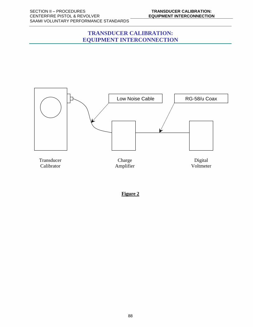
SECTION II – PROCEDURES CENTERFIRE PISTOL & REVOLVER
TRANSDUCER CALIBRATION: EQUIPMENT INTERCONNECTION
SAAMI VOLUNTARY PERFORMANCE STANDARDS
88
TRANSDUCER CALIBRATION:
EQUIPMENT INTERCONNECTION
Transducer Charge Digital
Calibrator Amplifier Voltmeter
Figure 2
Low Noise Cable RG-58/u Coax
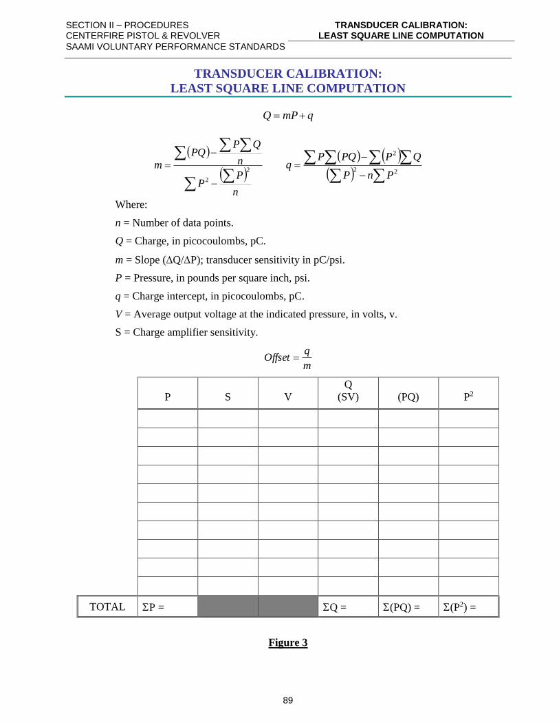
SECTION II – PROCEDURES CENTERFIRE PISTOL & REVOLVER
TRANSDUCER CALIBRATION: LEAST SQUARE LINE COMPUTATION
SAAMI VOLUNTARY PERFORMANCE STANDARDS
89
TRANSDUCER CALIBRATION:
LEAST SQUARE LINE COMPUTATION
qmPQ +=
( )
( )n
PP
n
QPPQ
m2
2
−
−
= ( ) ( )
( )
−
−=
22
2
PnP
QPPQPq
Where:
n = Number of data points.
Q = Charge, in picocoulombs, pC.
m = Slope (Q/P); transducer sensitivity in pC/psi.
P = Pressure, in pounds per square inch, psi.
q = Charge intercept, in picocoulombs, pC.
V = Average output voltage at the indicated pressure, in volts, v.
S = Charge amplifier sensitivity.
m
qOffset =
P
S
V
Q
(SV)
(PQ)
P2
TOTAL P = Q = (PQ) = (P2) =
Figure 3
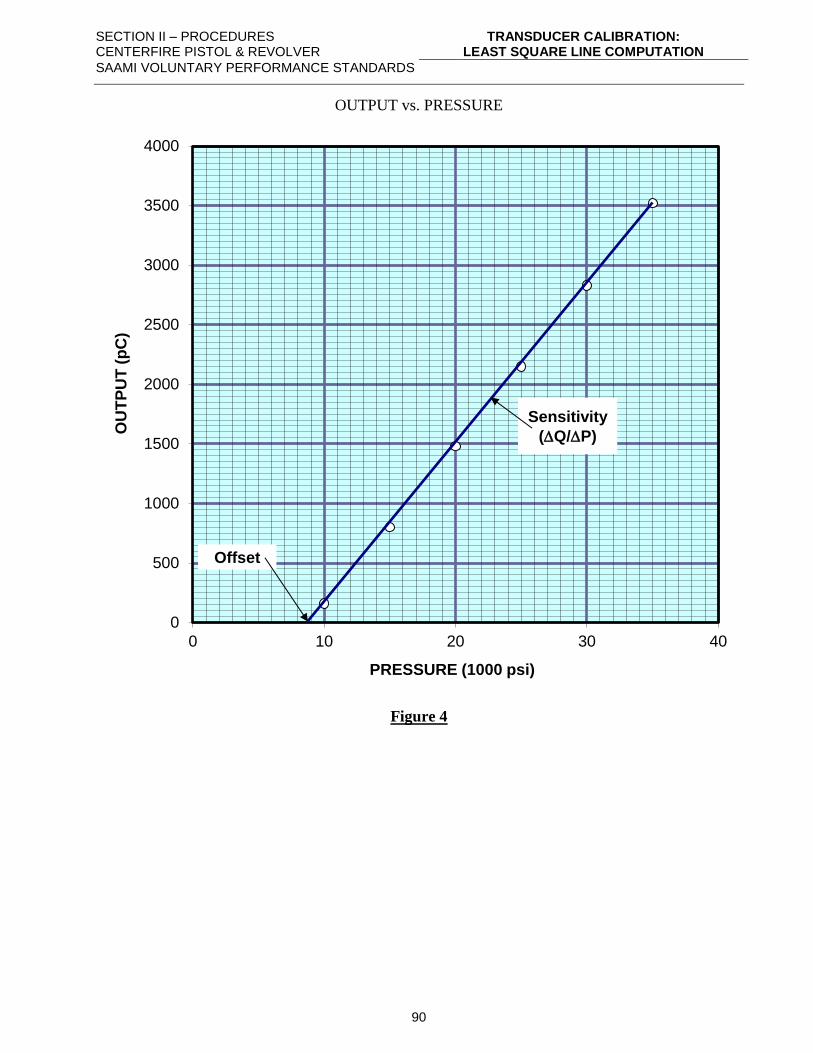
SECTION II – PROCEDURES CENTERFIRE PISTOL & REVOLVER
TRANSDUCER CALIBRATION: LEAST SQUARE LINE COMPUTATION
SAAMI VOLUNTARY PERFORMANCE STANDARDS
90
OUTPUT vs. PRESSURE
Figure 4
0
500
1000
1500
2000
2500
3000
3500
4000
0 10 20 30 40
OU
TP
UT
(p
C)
PRESSURE (1000 psi)
Sensitivity
(Q/P)
Offset
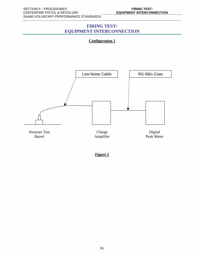
SECTION II – PROCEDURES CENTERFIRE PISTOL & REVOLVER
FIRING TEST: EQUIPMENT INTERCONNECTION
SAAMI VOLUNTARY PERFORMANCE STANDARDS
91
FIRING TEST:
EQUIPMENT INTERCONNECTION
Configuration 1
Pressure Test Charge Digital
Barrel Amplifier Peak Meter
Figure 5
Low Noise Cable RG-58/u Coax
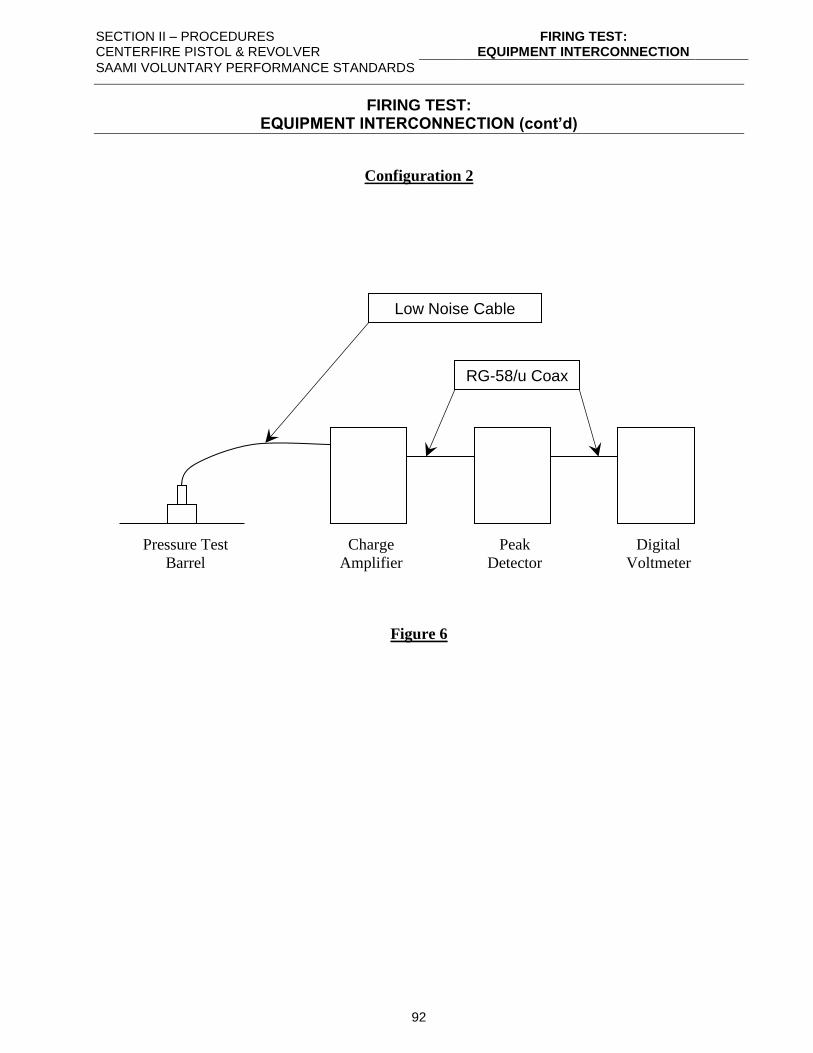
SECTION II – PROCEDURES CENTERFIRE PISTOL & REVOLVER
FIRING TEST: EQUIPMENT INTERCONNECTION
SAAMI VOLUNTARY PERFORMANCE STANDARDS
92
FIRING TEST: EQUIPMENT INTERCONNECTION (cont’d)
Configuration 2
Pressure Test Charge Peak Digital
Barrel Amplifier Detector Voltmeter
Figure 6
Low Noise Cable
RG-58/u Coax
SECTION II – PROCEDURES CENTERFIRE PISTOL & REVOLVER
REFERENCE AMMUNITION: USE
SAAMI VOLUNTARY PERFORMANCE STANDARDS
93
REFERENCE AMMUNITION:
USE
A. PURPOSE
Reference Ammunition is for the purpose of relating pressure and velocity test results at all
ranges.
B. PROCUREMENT
Reference Ammunition is procured as noted in Section III – page 128.
C. USE
The use and usefulness of Reference Ammunition in connection with the testing of ammunition
for velocity and pressure is predicated upon two basic assumptions as follows:
1. Associated with a given batch of Reference Ammunition at a given time is an assessed
average velocity, an assessed average pressure, as well as upper and lower limits for each,
which the averages of any ten round test may be expected to fall within when:
a. The reference ammunition manufacturer has applied appropriate safeguards to assure
homogeneity of the lot.
b. The ammunition is tested only after being conditioned under controlled temperature and
humidity.
c. The ammunition is tested in equipment compliant with Section III recommendations.
d. The ammunition is handled in strict accordance with Section II recommendations.
e. All auxiliary measuring equipment has been set up in accordance with Section II
recommendations and is in proper working condition.
2. Although there will be changes over time in the velocity and pressure assessments, the
changes occur sufficiently slowly to be detected by periodic reassessments before they have
achieved a magnitude sufficient to impair the usefulness of the reference rounds. In other
words, the velocity and pressure assessments are reasonably stable with time.
The average velocity and pressure that may be developed by a sample of Reference Ammunition in
any given standard test barrel under given test conditions may be different from the results obtained
under the test conditions referred to above in assumption 1 due to minor equipment variations and
statistical sampling error. Such values may be perfectly real, providing the auxiliary equipment
introduces no errors.
In order to realize the benefits of Reference Ammunition, some rules must be adhered to.
Nevertheless, each individual user must make the final judgments concerning how often it is used
and the use of the data. It is important, therefore, that there be a clear realization of what it can and
what it cannot tell the ammunition tester.
Reference Ammunition cannot guarantee the absolute accuracy of any test system. It does, however,
provide simple and direct data from any given ammunition test equipment to determine how closely
it relates to the acceptable, average system as used by SAAMI members.
SECTION II – PROCEDURES CENTERFIRE PISTOL & REVOLVER
REFERENCE AMMUNITION: USE
SAAMI VOLUNTARY PERFORMANCE STANDARDS
94
In line with the preceding discussion, the following recommendations are made for the use of
Reference ammunition:
A. Each Reference Lot should be conditioned before use.
B. How often Reference Ammunition is used shall be determined by the user's internal
practices, taking into account such factors as historical knowledge of barrel life.
C. The recommended minimum sample shall be ten rounds.
D. In the event the observed average velocity and pressure of the sample falls within the
Inclusion Limits, a correction may or may not be applied according to the procedure
given in Step G at the discretion of the user.
E. If one average is outside of the Inclusion Limits and the other within, the average that
exceeds the limits shall be corrected according to the procedure given in Step G.
F. If both averages are outside of the Inclusion Limits, both the velocity and pressure shall
be corrected according to the procedure in Step G.
G. If the correction is to be applied, the correction shall be the difference between the
assessed value and the observed average of the test.
SECTION II – PROCEDURES CENTERFIRE PISTOL & REVOLVER
REFERENCE AMMUNITION: SECONDARY REFERENCE AMMUNITION
SAAMI VOLUNTARY PERFORMANCE STANDARDS
95
REFERENCE AMMUNITION:
SECONDARY REFERENCE AMMUNITION
Occasionally, a test station will have a need for an inordinately large supply of Reference
Ammunition in considerable excess to the usual volume. In order to minimize the premature
exhaustion of any particular lot, it is suggested that the station create its own secondary reference lot
to fill the special need.
A secondary reference lot should consist of a supply of off-the-shelf ammunition, each box bearing
the same manufacturer’s code name. The secondary reference lot should be approximately
equivalent in bullet weight, average velocity, and average pressure to the Reference Ammunition
that it replaces.
SECTION II – PROCEDURES CENTERFIRE PISTOL & REVOLVER
REFERENCE AMMUNITION: NEW LOTS
SAAMI VOLUNTARY PERFORMANCE STANDARDS
96
REFERENCE AMMUNITION:
NEW LOTS
I. GENERAL
Reference Ammunition lots have been established for those lots or loads designated by the
Technical Committee. Responsibility for production of each of the selected lots is assigned to
a member company that is responsible for maintaining a supply. A five-year supply is
recommended. It is desirable that Reference Ammunition be consistent with Standard values
for that particular round.
When a producer has prepared a new lot, it shall be his responsibility to announce the lot to the
SAAMI Technical Office2, giving a tentative assessment and other data. (An example of the
recommended format for this announcement appears later in this section.)
The producer shall supply, at the time of the announcement of the new lot, to each member of
the Reference Ammunition Group that has the capability to test that cartridge, one box of the
new lot for immediate test. A current list of the testing capabilities of the Reference
Ammunition Group is available from the SAAMI Technical Office on request.
The SAAMI Technical Office will announce the availability of the new lot to the participating
ranges, giving the tentative assessment and other pertinent data. (An example of the
recommended format for this announcement appears later in this section.)
II. METHOD OF ASSESSMENT
Before announcing a new lot of reference ammunition to the SAAMI Technical Office, the
manufacturer should make sufficient tests to determine Tentative Values of pressure and
velocity for the new lot.
1. The test barrels shall conform to the SAAMI specifications for internal dimensions, length
and piston / piezo gauge location. (Refer to Section III.)
2. Counter-chronographs and photoelectric screens shall be used in velocity measurements.
(See Section III.)
3. Ammunition shall be conditioned for a minimum of 24 hours at 70° ± 2°F (21.1° ± 1.1°C)
with relative humidity of 60% ± 5% before firing.
4. For copper crusher assessments, only an approved crusher lot shall be used in pressure
measurements. (See Section III – page 109 for proper crusher sizes.)
2 Refer to Section III - page 130, for current contact information for the SAAMI Technical Office.
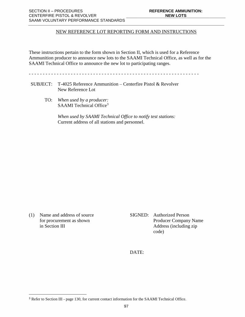
SECTION II – PROCEDURES CENTERFIRE PISTOL & REVOLVER
REFERENCE AMMUNITION: NEW LOTS
SAAMI VOLUNTARY PERFORMANCE STANDARDS
97
NEW REFERENCE LOT REPORTING FORM AND INSTRUCTIONS
These instructions pertain to the form shown in Section II, which is used for a Reference
Ammunition producer to announce new lots to the SAAMI Technical Office, as well as for the
SAAMI Technical Office to announce the new lot to participating ranges.
- - - - - - - - - - - - - - - - - - - - - - - - - - - - - - - - - - - - - - - - - - - - - - - - - - - - - - - - - - - - -
SUBJECT: T-4025 Reference Ammunition – Centerfire Pistol & Revolver
New Reference Lot
TO: When used by a producer:
SAAMI Technical Office3
When used by SAAMI Technical Office to notify test stations:
Current address of all stations and personnel.
(1) Name and address of source SIGNED: Authorized Person
for procurement as shown Producer Company Name
in Section III Address (including zip
code)
DATE:
3 Refer to Section III - page 130, for current contact information for the SAAMI Technical Office.
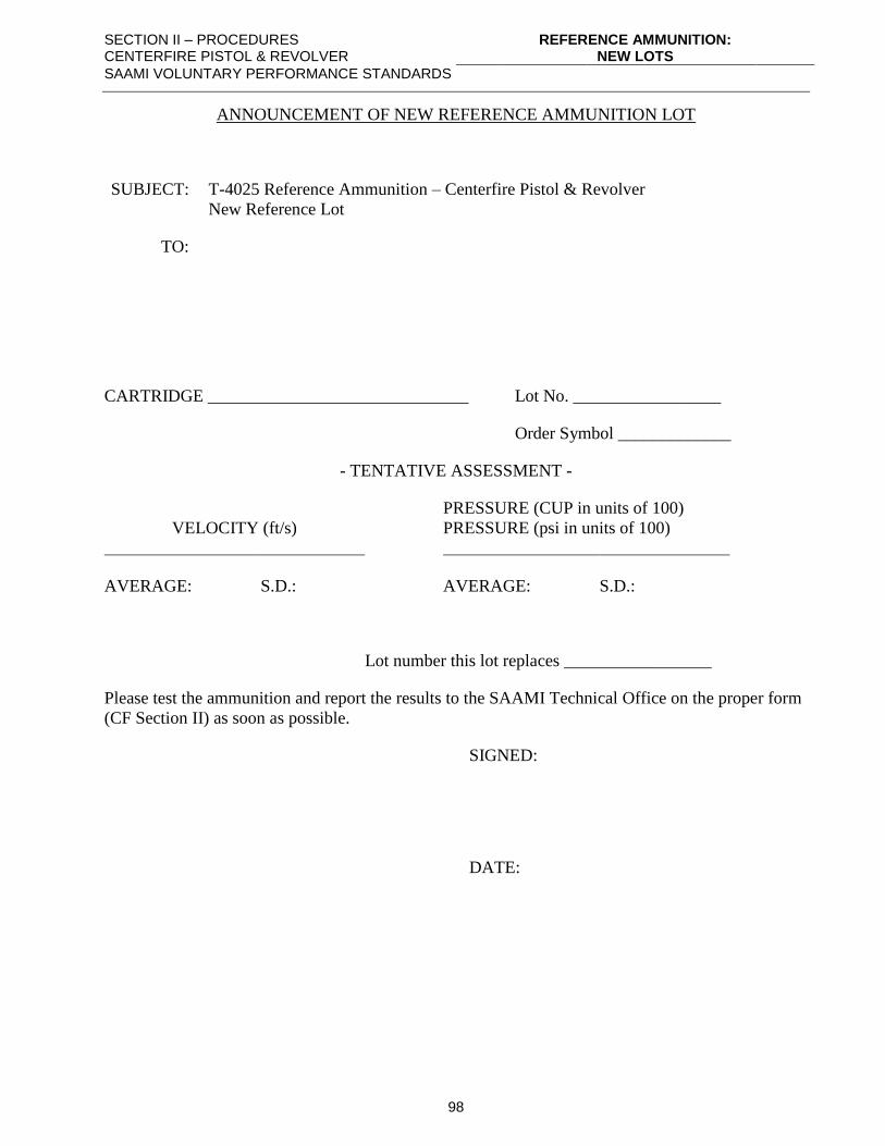
SECTION II – PROCEDURES CENTERFIRE PISTOL & REVOLVER
REFERENCE AMMUNITION: NEW LOTS
SAAMI VOLUNTARY PERFORMANCE STANDARDS
98
ANNOUNCEMENT OF NEW REFERENCE AMMUNITION LOT
SUBJECT: T-4025 Reference Ammunition – Centerfire Pistol & Revolver
New Reference Lot
TO:
CARTRIDGE ______________________________ Lot No. _________________
Order Symbol _____________
- TENTATIVE ASSESSMENT -
VELOCITY (ft/s)
PRESSURE (CUP in units of 100)
PRESSURE (psi in units of 100)
AVERAGE:
S.D.:
AVERAGE:
S.D.:
Lot number this lot replaces _________________
Please test the ammunition and report the results to the SAAMI Technical Office on the proper form
(CF Section II) as soon as possible.
SIGNED:
DATE:
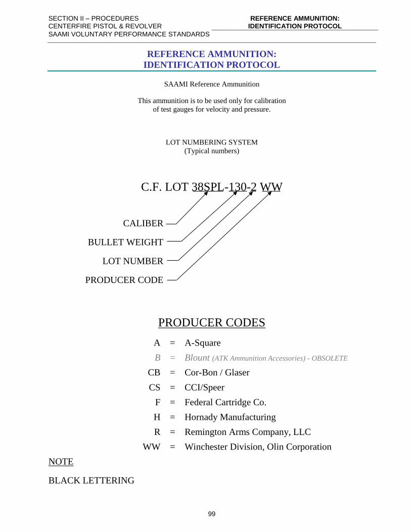
SECTION II – PROCEDURES CENTERFIRE PISTOL & REVOLVER
REFERENCE AMMUNITION: IDENTIFICATION PROTOCOL
SAAMI VOLUNTARY PERFORMANCE STANDARDS
99
REFERENCE AMMUNITION:
IDENTIFICATION PROTOCOL
SAAMI Reference Ammunition
This ammunition is to be used only for calibration
of test gauges for velocity and pressure.
LOT NUMBERING SYSTEM
(Typical numbers)
C.F. LOT 38SPL-130-2 WW
CALIBER
BULLET WEIGHT
LOT NUMBER
PRODUCER CODE
PRODUCER CODES
A = A-Square
B = Blount (ATK Ammunition Accessories) - OBSOLETE
CB = Cor-Bon / Glaser
CS = CCI/Speer
F = Federal Cartridge Co.
H = Hornady Manufacturing
R = Remington Arms Company, LLC
WW = Winchester Division, Olin Corporation
NOTE
BLACK LETTERING
SECTION II – PROCEDURES CENTERFIRE PISTOL & REVOLVER
REFERENCE AMMUNITION: PERIODIC ASSESSMENT
SAAMI VOLUNTARY PERFORMANCE STANDARDS
100
REFERENCE AMMUNITION:
PERIODIC ASSESSMENT
I. PROCUREMENT
Reference ammunition is procured as noted in Section III.
II. PERIODIC TESTS
A. STATIONS
1. All test conditions should conform as closely as possible to those prescribed in
this Standard, and the following conditions should be met:
a) Tests should consist of ten (10) rounds for velocity and pressure fired
during a single day.
b) Test barrels shall conform to SAAMI specifications for internal
dimensions, length, and piston/transducer location.
c) Counter-chronographs and photoelectric screens (or equivalents) shall be
used in velocity measurements. (See Section III.)
d) Ammunition shall be conditioned for 72 hours at 70° ± 2°F (21.1° ±
1.1°C) with relative humidity of 60% ± 5% before firing.
e) Only an approved crusher lot shall be used in pressure measurements.
(See Section III, page 109 for proper crusher sizes.)
2. Each station should report results of its firing in the test on approved forms to the
SAAMI Technical Office1. A sample of this report form is presented later in this
section.
B. CLEARING HOUSE
1. The SAAMI Technical Office serves as the clearinghouse for all Reference
Ammunition ballistics and related information. It shall be the responsibility of the
SAAMI Technical Office to schedule testing and to assemble and distribute
results of periodic tests. This should be done on the proper Reference
Ammunition report form. (Sample, Section II.)
2. The Reference Ammunition Report shall contain the average pressure, velocity,
and related standard deviations as reported by each station for that lot. From this
data, the SAAMI Technical Office will calculate and report the Raw Average,
Corrected Average, Standard Deviation Averages, and Inclusion Limits.
3. To obtain the Raw Averages, the SAAMI Technical Office shall include the 10-
round averages for the pressure and velocity of all reporting stations and the first
and second previous assessment value. If the 10-round average from any station
1 Refer to Section III - page 130, for current contact information for the SAAMI Technical Office.
SECTION II – PROCEDURES CENTERFIRE PISTOL & REVOLVER
REFERENCE AMMUNITION: PERIODIC ASSESSMENT
SAAMI VOLUNTARY PERFORMANCE STANDARDS
101
varies from the Raw Average by more than plus or minus 35 fps in velocity OR
plus or minus 2,500 CUP/psi in pressure, the pressure or velocity data from that
(those) station(s) should be discarded. The mean pressure and velocity data
should be recalculated omitting the discarded data. The new mean is the
“Corrected Average”. If the mean pressure value of a station is outside of the
limits as defined above, but the velocity is in, the pressure data should be dropped
and the velocity data retained. The converse is true as well. Using the Corrected
Averages, the Inclusion Limits are determined as follows:
VELOCITY: MEAN = Same as Corrected Average
HIGH = MEAN + 35 fps
LOW = MEAN - 35 fps
PRESSURE: MEAN = Same as Corrected Average
HIGH = MEAN + 2,500 CUP/psi
LOW = MEAN – 2,500 CUP/psi
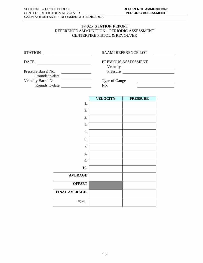
SECTION II – PROCEDURES CENTERFIRE PISTOL & REVOLVER
REFERENCE AMMUNITION: PERIODIC ASSESSMENT
SAAMI VOLUNTARY PERFORMANCE STANDARDS
102
T-4025 STATION REPORT
REFERENCE AMMUNITION – PERIODIC ASSESSMENT
CENTERFIRE PISTOL & REVOLVER
STATION SAAMI REFERENCE LOT
DATE PREVIOUS ASSESSMENT
Velocity
Pressure Barrel No. Pressure
Rounds to-date
Velocity Barrel No. Type of Gauge
Rounds to-date No.
VELOCITY PRESSURE
1.
2.
3.
4.
5.
6.
7.
8.
9.
10.
AVERAGE
OFFSET
FINAL AVERAGE.
(−)
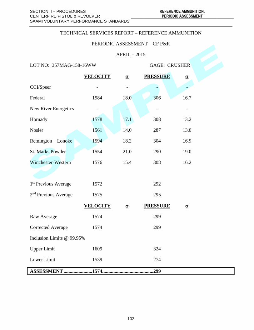
SECTION II – PROCEDURES CENTERFIRE PISTOL & REVOLVER
REFERENCE AMMUNITION: PERIODIC ASSESSMENT
SAAMI VOLUNTARY PERFORMANCE STANDARDS
103
TECHNICAL SERVICES REPORT – REFERENCE AMMUNITION
PERIODIC ASSESSMENT – CF P&R
APRIL – 2015
LOT NO: 357MAG-158-16WW GAGE: CRUSHER
VELOCITY PRESSURE
CCI/Speer - - - -
Federal 1584 18.0 306 16.7
New River Energetics - - - -
Hornady 1578 17.1 308 13.2
Nosler 1561 14.0 287 13.0
Remington – Lonoke 1594 18.2 304 16.9
St. Marks Powder 1554 21.0 290 19.0
Winchester-Western 1576 15.4 308 16.2
1st Previous Average 1572 292
2nd Previous Average 1575 295
VELOCITY PRESSURE
Raw Average 1574 299
Corrected Average 1574 299
Inclusion Limits @ 99.95%
Upper Limit 1609 324
Lower Limit 1539 274
ASSESSMENT .......................1574.........................................299
SECTION II – PROCEDURES CENTERFIRE PISTOL & REVOLVER
PROCEDURE: FRANGIBILITY TESTING
SAAMI VOLUNTARY PERFORMANCE STANDARDS
104
PROCEDURE:
FRANGIBILITY TESTING
NOTE: Refer to Section III for equipment recommendations and nomenclature.
(1) The collection box shall be thoroughly cleaned of residue from previous test.
(2) The impact plate shall be at an angle of 45° ± 5° to the line of fire.
(3) The collection box shall be positioned to provide a point of impact within ± 2” (51 mm) of the
center of the impact plate.
(4) A new retention board shall be positioned on the front of the collection box.
(5) A sample size of ten (10) rounds shall be fired.
(6) The retention board shall be examined for evidence of penetration completely through the
board by bullet fragments coming out of the collection box. If any such penetrations are
present, the bullet being tested fails to meet the qualification for “frangible”.
NOTE: Fragments that are captured in the retention board, even though they have
penetrated both panels of the board, shall not be considered a failure, but the fragments shall
be added to the collected debris for evaluation against other standards.
(7) Bullet fragments and debris from the test shall be carefully collected to ensure the greatest
possible recovery of bullet particles.
(8) The debris collected shall be examined and foreign matter unrelated to the bullet breakup
carefully removed.
(9) The collected debris shall be weighed and the weight recorded.
(10) The debris shall be carefully inspected and the largest individual pieces removed and
separately weighed, with each weight being separately recorded.
(11) The weights of the individual fragments and collected debris shall be compared to the
characteristics presented in Section I.
SECTION III – EQUIPMENT CENTERFIRE PISTOL & REVOLVER
EQUIPMENT: VELOCITY & COPPER CRUSHER PRESSURE TESTING
SAAMI VOLUNTARY PERFORMANCE STANDARDS
105
EQUIPMENT:
VELOCITY & COPPER CRUSHER PRESSURE TESTING
NOTE: Refer to Section III – page 130, Supplier Contact Information, for detailed information on
contacting the manufacturers of listed products and the SAAMI Technical Office.
1. Electronic Counter Chronograph – 100 kilohertz, minimum
a) Oehler Research
b) Electronic Counters, Inc.
c) Other equivalent.
2. Table of velocity vs. time of flight or electronic calculator.
NOTE: Items (1) and (2) may be replaced by a direct-reading velocity chronograph or
integrated ballistic instrumentation system with equivalent accuracy and precision.
3. Photoelectric screens
a) Oehler Research
b) Electronic Counters, Inc.
c) Other equivalent.
4. Universal Receiver
a) Ulysses Machine Company
b) H-S Precision, Inc.
c) Other equivalent.
5. Test Barrel (Drawings of test barrels are presented in Section III).
a) H-S Precision, Inc.
b) Wiseman
c) Wilson Arms Company
d) Hart Rifle Barrels, Inc.
e) Krieger Barrels, Inc.
f) Or equivalent.
6. Piston (Section III)
7. Piston and piston hole gauges (Section III)
8. Oil, SAE 30
9. Gas check (Section III)
10. Gas check tools – seating and knockout (Section III)
11. Gas check wax (Section III)
12. Copper crushers
0.146” x 0.400”
0.225” x 0.400”
Manufactured (Section III)
Winchester Division, Olin Corporation.
13. Tarage table (supplied with each lot of purchased crushers; see Section III, page 110 for sample
table)
SECTION III – EQUIPMENT CENTERFIRE PISTOL & REVOLVER
EQUIPMENT: VELOCITY & COPPER CRUSHER PRESSURE TESTING
SAAMI VOLUNTARY PERFORMANCE STANDARDS
106
0.146” x 0.400” when used with 0.146” piston
0.146” x 0.400” when used with 0.206” piston
0.225” x 0.400” when used with 0.206” piston
14. Measuring device for compressed crushers
a) Micrometer, 1” capacity, minimum, 0.0005” precision.
b) Platform dial indicator, 1” capacity, minimum, 0.0005” precision.
c) Other device capable of measuring lengths up to 0.500” with a minimum precision of
0.0005”
15. Reference ammunition. (Refer to Section III – page 127 for supply sources.)
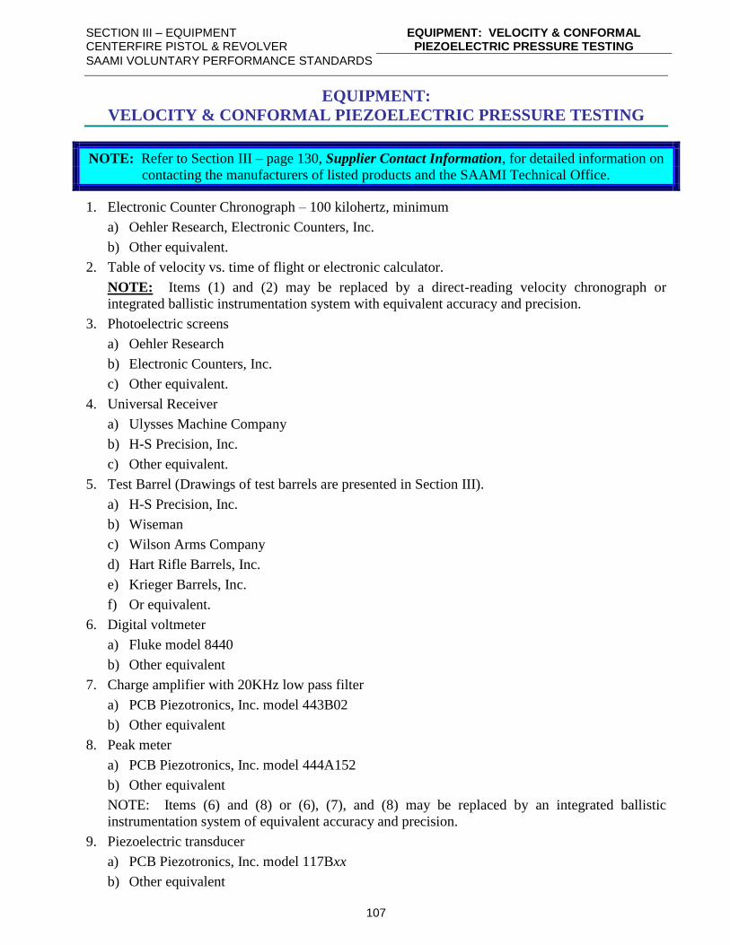
SECTION III – EQUIPMENT CENTERFIRE PISTOL & REVOLVER
EQUIPMENT: VELOCITY & CONFORMAL PIEZOELECTRIC PRESSURE TESTING
SAAMI VOLUNTARY PERFORMANCE STANDARDS
107
EQUIPMENT:
VELOCITY & CONFORMAL PIEZOELECTRIC PRESSURE TESTING
NOTE: Refer to Section III – page 130, Supplier Contact Information, for detailed information on
contacting the manufacturers of listed products and the SAAMI Technical Office.
1. Electronic Counter Chronograph – 100 kilohertz, minimum
a) Oehler Research, Electronic Counters, Inc.
b) Other equivalent.
2. Table of velocity vs. time of flight or electronic calculator.
NOTE: Items (1) and (2) may be replaced by a direct-reading velocity chronograph or
integrated ballistic instrumentation system with equivalent accuracy and precision.
3. Photoelectric screens
a) Oehler Research
b) Electronic Counters, Inc.
c) Other equivalent.
4. Universal Receiver
a) Ulysses Machine Company
b) H-S Precision, Inc.
c) Other equivalent.
5. Test Barrel (Drawings of test barrels are presented in Section III).
a) H-S Precision, Inc.
b) Wiseman
c) Wilson Arms Company
d) Hart Rifle Barrels, Inc.
e) Krieger Barrels, Inc.
f) Or equivalent.
6. Digital voltmeter
a) Fluke model 8440
b) Other equivalent
7. Charge amplifier with 20KHz low pass filter
a) PCB Piezotronics, Inc. model 443B02
b) Other equivalent
8. Peak meter
a) PCB Piezotronics, Inc. model 444A152
b) Other equivalent
NOTE: Items (6) and (8) or (6), (7), and (8) may be replaced by an integrated ballistic
instrumentation system of equivalent accuracy and precision.
9. Piezoelectric transducer
a) PCB Piezotronics, Inc. model 117Bxx
b) Other equivalent
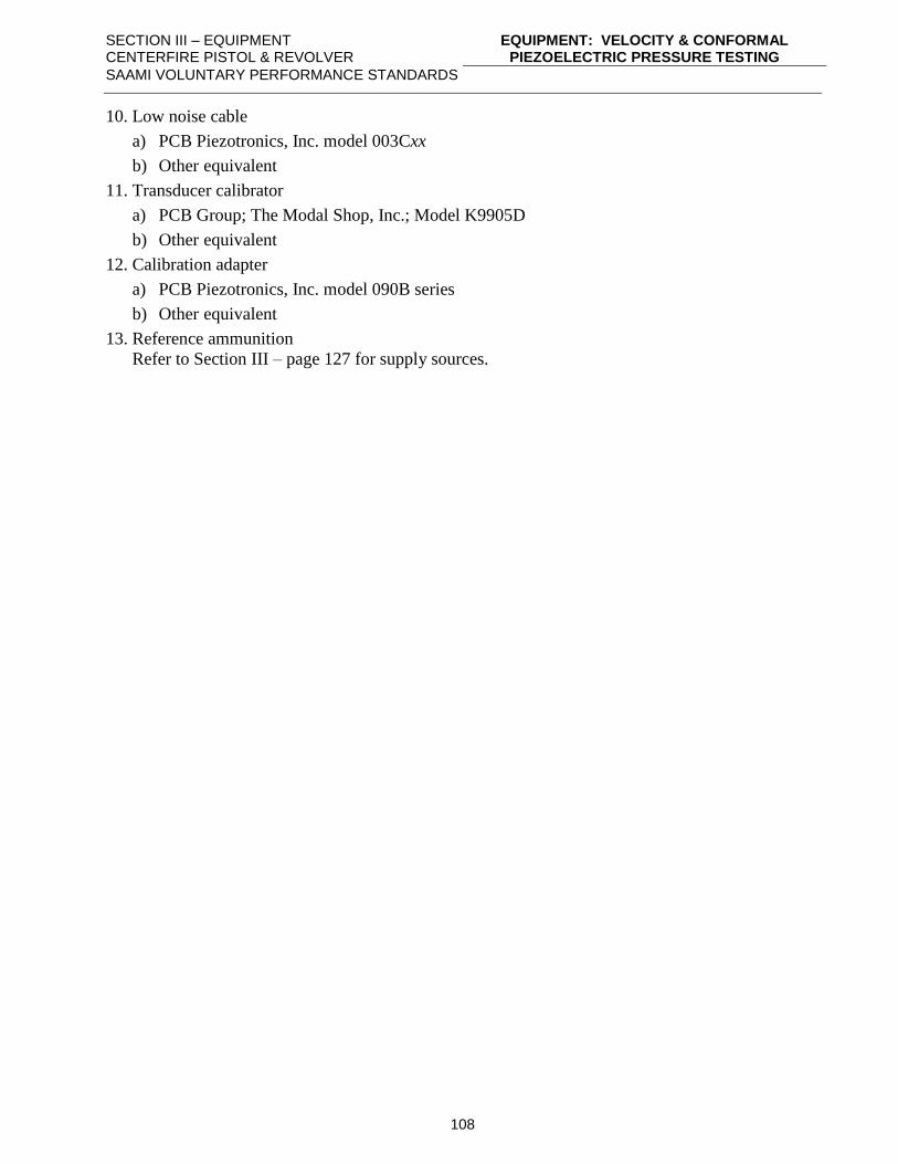
SECTION III – EQUIPMENT CENTERFIRE PISTOL & REVOLVER
EQUIPMENT: VELOCITY & CONFORMAL PIEZOELECTRIC PRESSURE TESTING
SAAMI VOLUNTARY PERFORMANCE STANDARDS
108
10. Low noise cable
a) PCB Piezotronics, Inc. model 003Cxx
b) Other equivalent
11. Transducer calibrator
a) PCB Group; The Modal Shop, Inc.; Model K9905D
b) Other equivalent
12. Calibration adapter
a) PCB Piezotronics, Inc. model 090B series
b) Other equivalent
13. Reference ammunition
Refer to Section III – page 127 for supply sources.
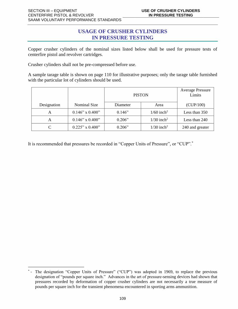
SECTION III – EQUIPMENT CENTERFIRE PISTOL & REVOLVER
USE OF CRUSHER CYLINDERS IN PRESSURE TESTING
SAAMI VOLUNTARY PERFORMANCE STANDARDS
109
USAGE OF CRUSHER CYLINDERS
IN PRESSURE TESTING
Copper crusher cylinders of the nominal sizes listed below shall be used for pressure tests of
centerfire pistol and revolver cartridges.
Crusher cylinders shall not be pre-compressed before use.
A sample tarage table is shown on page 110 for illustrative purposes; only the tarage table furnished
with the particular lot of cylinders should be used.
PISTON
Average Pressure
Limits
Designation Nominal Size Diameter Area (CUP/100)
A 0.146” x 0.400” 0.146” 1/60 inch2 Less than 350
A 0.146” x 0.400” 0.206” 1/30 inch2 Less than 240
C 0.225” x 0.400” 0.206” 1/30 inch2 240 and greater
It is recommended that pressures be recorded in “Copper Units of Pressure”, or “CUP”.*
* - The designation “Copper Units of Pressure” (“CUP”) was adopted in 1969, to replace the previous
designation of “pounds per square inch.” Advances in the art of pressure-sensing devices had shown that
pressures recorded by deformation of copper crusher cylinders are not necessarily a true measure of
pounds per square inch for the transient phenomena encountered in sporting arms ammunition.
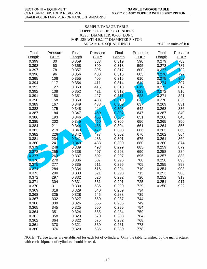
SECTION III – EQUIPMENT CENTERFIRE PISTOL & REVOLVER
SAMPLE TARAGE TABLE 0.225” x 0.400” COPPER WITH 0.206” PISTON
SAAMI VOLUNTARY PERFORMANCE STANDARDS
110
SAMPLE TARAGE TABLE
COPPER CRUSHER CYLINDERS
0.225” DIAMETER, 0.400” LONG
FOR USE WITH 0.206” DIAMETER PISTON
AREA = 1/30 SQUARE INCH *CUP in units of 100
Final Pressure Final Pressure Final Pressure Final Pressure Length CUP* Length CUP* Length CUP* Length CUP* 0.399 30 0.359 383 0.319 590 0.279 783 0.398 60 0.358 390 0.318 595 0.278 787 0.397 78 0.357 395 0.317 600 0.277 792 0.396 96 0.356 400 0.316 605 0.276 797 0.395 106 0.355 405 0.315 610 0.275 802 0.394 117 0.354 411 0.314 614 0.274 807 0.393 127 0.353 416 0.313 619 0.273 812 0.392 138 0.352 421 0.312 623 0.272 816 0.391 150 0.351 427 0.311 628 0.271 821 0.390 158 0.350 433 0.310 633 0.270 826 0.389 167 0.349 438 0.309 637 0.269 831 0.388 175 0.348 444 0.308 642 0.268 836 0.387 184 0.347 450 0.307 647 0.267 840 0.386 193 0.346 455 0.306 651 0.266 845 0.385 202 0.345 460 0.305 656 0.265 850 0.384 211 0.344 466 0.304 661 0.264 855 0.383 219 0.343 471 0.303 666 0.263 860 0.382 226 0.342 477 0.302 670 0.262 864 0.381 234 0.341 483 0.301 675 0.261 869 0.380 241 0.340 488 0.300 680 0.260 874 0.379 248 0.339 493 0.299 685 0.259 879 0.378 255 0.338 497 0.298 690 0.258 884 0.377 263 0.337 502 0.297 695 0.257 888 0.376 270 0.336 507 0.296 700 0.256 893 0.375 277 0.335 511 0.295 705 0.255 898 0.374 284 0.334 516 0.294 710 0.254 903 0.373 290 0.333 521 0.293 715 0.253 908 0.372 297 0.332 526 0.292 720 0.252 913 0.371 304 0.331 531 0.291 725 0.251 917 0.370 311 0.330 535 0.290 729 0.250 922 0.369 318 0.329 540 0.289 734 0.368 325 0.328 545 0.288 739 0.367 332 0.327 550 0.287 744 0.366 339 0.326 555 0.286 749 0.365 345 0.325 560 0.285 754 0.364 351 0.324 565 0.284 759 0.363 358 0.323 570 0.283 764 0.362 364 0.322 575 0.282 768 0.361 370 0.321 580 0.281 773 0.360 376 0.320 585 0.280 778
NOTE: Tarage tables are established for each lot of cylinders. Only the table furnished by the manufacturer
with each shipment of cylinders should be used.
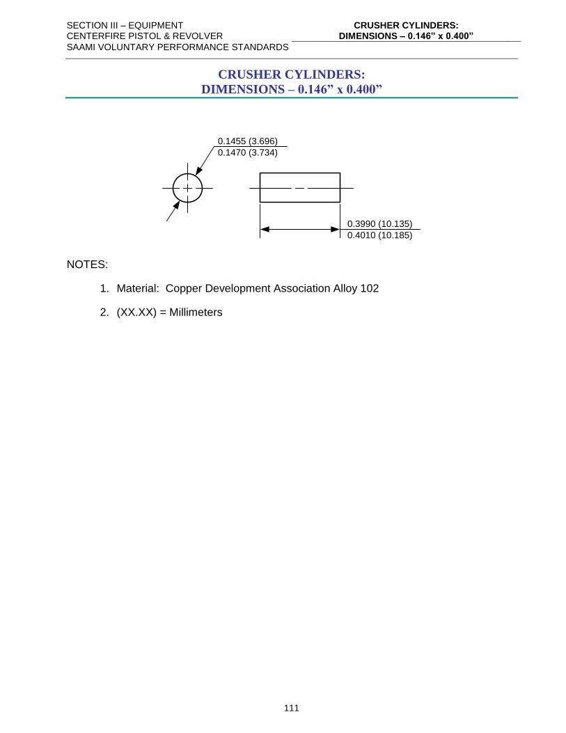
SECTION III – EQUIPMENT CENTERFIRE PISTOL & REVOLVER
CRUSHER CYLINDERS: DIMENSIONS – 0.146” x 0.400”
SAAMI VOLUNTARY PERFORMANCE STANDARDS
111
CRUSHER CYLINDERS:
DIMENSIONS – 0.146” x 0.400”
0.1455 (3.696)
0.1470 (3.734)
0.3990 (10.135)
0.4010 (10.185)
NOTES:
1. Material: Copper Development Association Alloy 102
2. (XX.XX) = Millimeters
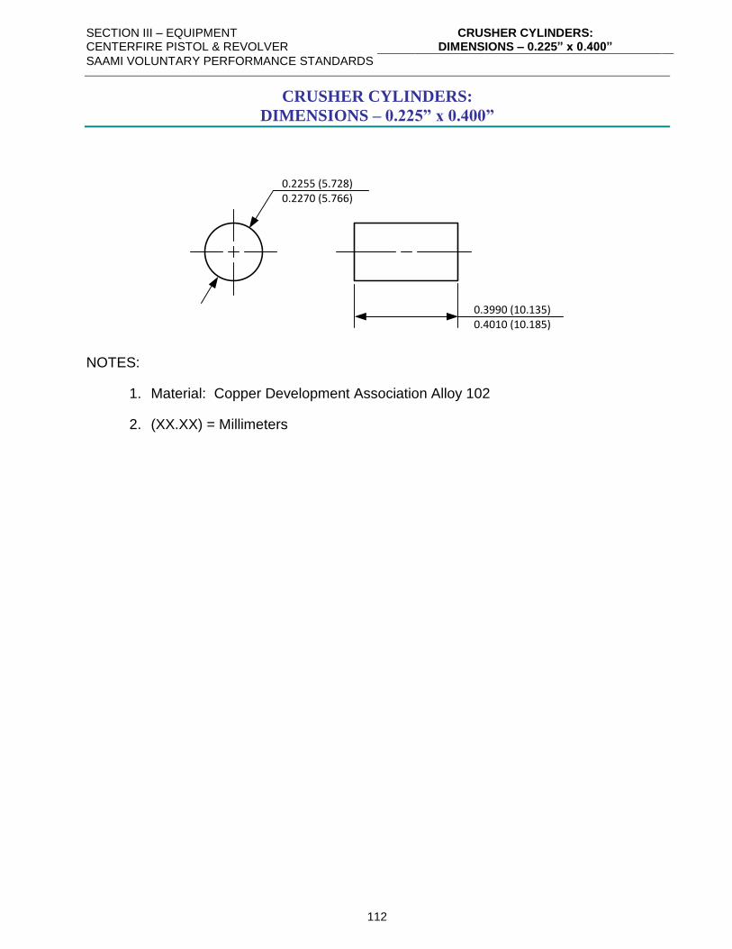
SECTION III – EQUIPMENT CENTERFIRE PISTOL & REVOLVER
CRUSHER CYLINDERS: DIMENSIONS – 0.225” x 0.400”
SAAMI VOLUNTARY PERFORMANCE STANDARDS
112
CRUSHER CYLINDERS:
DIMENSIONS – 0.225” x 0.400”
0.2255 (5.728)0.2270 (5.766)
0.3990 (10.135)0.4010 (10.185)
NOTES:
1. Material: Copper Development Association Alloy 102
2. (XX.XX) = Millimeters
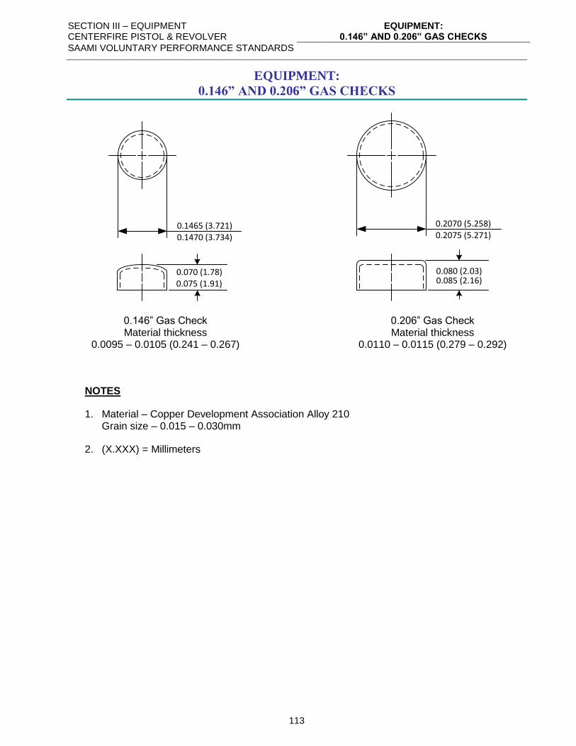
SECTION III – EQUIPMENT CENTERFIRE PISTOL & REVOLVER
EQUIPMENT: 0.146” AND 0.206” GAS CHECKS
SAAMI VOLUNTARY PERFORMANCE STANDARDS
113
EQUIPMENT:
0.146” AND 0.206” GAS CHECKS
0.080 (2.03)0.085 (2.16)
0.070 (1.78)0.075 (1.91)
0.2070 (5.258)0.2075 (5.271)
0.1465 (3.721)0.1470 (3.734)
0.146” Gas Check 0.206” Gas Check Material thickness Material thickness 0.0095 – 0.0105 (0.241 – 0.267) 0.0110 – 0.0115 (0.279 – 0.292)
NOTES
1. Material – Copper Development Association Alloy 210 Grain size – 0.015 – 0.030mm
2. (X.XXX) = Millimeters
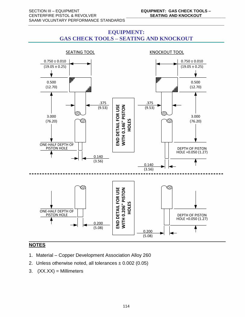
SECTION III – EQUIPMENT CENTERFIRE PISTOL & REVOLVER
EQUIPMENT: GAS CHECK TOOLS – SEATING AND KNOCKOUT
SAAMI VOLUNTARY PERFORMANCE STANDARDS
114
EQUIPMENT:
GAS CHECK TOOLS – SEATING AND KNOCKOUT
SEATING TOOL KNOCKOUT TOOL
0.750 ± 0.010
(19.05 ± 0.25)
0.500(12.70)
0.140(3.56)
3.000(76.20)
ONE-HALF DEPTH OF PISTON HOLE
0.140(3.56)
3.000(76.20)
DEPTH OF PISTONHOLE +0.050 (1.27)
0.750 ± 0.010
(19.05 ± 0.25)
0.500(12.70)
0.200(5.08)
0.200(5.08)
DEPTH OF PISTONHOLE +0.050 (1.27)
END
DET
AIL
FO
R U
SE
WIT
H 0
.14
6"
PIS
TON
H
OLE
S
END
DET
AIL
FO
R U
SE
WIT
H 0
.20
6"
PIS
TON
H
OLE
S
.375(9.53)
.375(9.53)
ONE-HALF DEPTH OF PISTON HOLE
NOTES
1. Material – Copper Development Association Alloy 260
2. Unless otherwise noted, all tolerances ± 0.002 (0.05)
3. (XX.XX) = Millimeters
SECTION III – EQUIPMENT CENTERFIRE PISTOL & REVOLVER
EQUIPMENT: GAS CHECK WAX
SAAMI VOLUNTARY PERFORMANCE STANDARDS
115
EQUIPMENT:
GAS CHECK WAX
INGREDIENTS
1. Beeswax ..................................................................................... 234.0 grams
2. Paraffin ........................................................................................... 6.0 grams
3. Vaseline.......................................................................................... 6.0 grams
4. Castor Oil ..................................................................................... 14.4 grams
5. Lead oxide (red lead) ................................................................... 72.0 grams
6. Iron oxide (Ferric oxide) .............................................................. 24.0 grams
7. Rosin ...................................................................................... 5% by volume
PREPARATION
The ingredients are weighed out in a vessel and heated in a steam bath until the waxes are
melted. The mixture is then removed from the steam bath and stirred vigorously until
slightly warm. The wax is then rolled out on a flat surface into sticks.
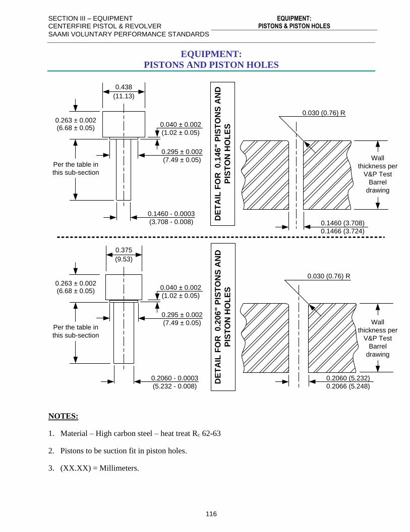
SECTION III – EQUIPMENT CENTERFIRE PISTOL & REVOLVER
EQUIPMENT: PISTONS & PISTON HOLES
SAAMI VOLUNTARY PERFORMANCE STANDARDS
116
EQUIPMENT:
PISTONS AND PISTON HOLES
0.438
(11.13)
Per the table in
this sub-section
DE
TA
IL F
OR
0
.14
6" P
IST
ON
S A
ND
PIS
TO
N H
OL
ES
0.263 ± 0.002(6.68 ± 0.05)
0.040 ± 0.002
(1.02 ± 0.05)
0.295 ± 0.002
(7.49 ± 0.05)
0.1460 - 0.0003
(3.708 - 0.008)
0.030 (0.76) R
0.1460 (3.708)
0.1466 (3.724)
Wall
thickness per
V&P Test
Barrel
drawing
0.375
(9.53)
DE
TA
IL F
OR
0
.20
6" P
IST
ON
S A
ND
PIS
TO
N H
OL
ES
0.263 ± 0.002(6.68 ± 0.05)
0.040 ± 0.002
(1.02 ± 0.05)
0.295 ± 0.002
(7.49 ± 0.05)
0.2060 - 0.0003
(5.232 - 0.008)
0.030 (0.76) R
0.2060 (5.232)
0.2066 (5.248)
Wall
thickness per
V&P Test
Barrel
drawing
Per the table in
this sub-section
NOTES:
1. Material – High carbon steel – heat treat Rc 62-63
2. Pistons to be suction fit in piston holes.
3. (XX.XX) = Millimeters.
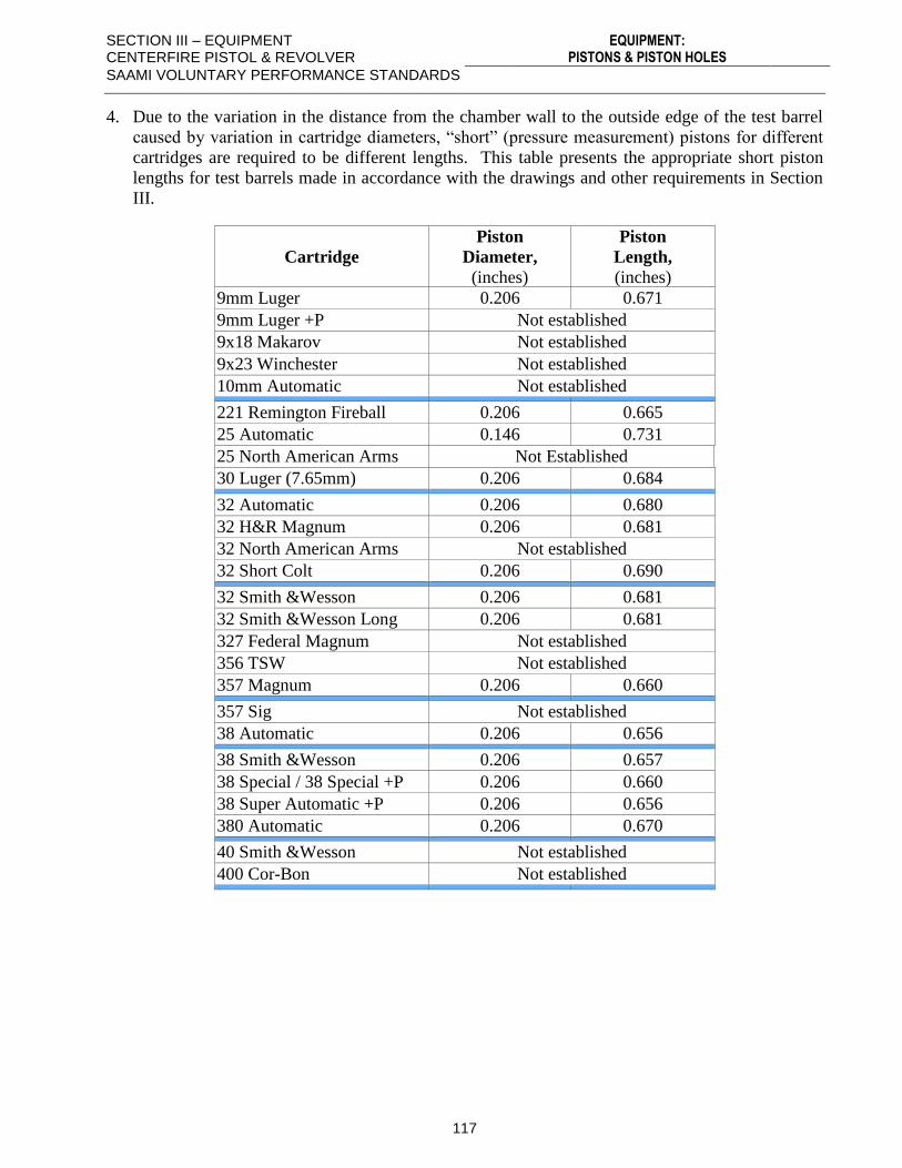
SECTION III – EQUIPMENT CENTERFIRE PISTOL & REVOLVER
EQUIPMENT: PISTONS & PISTON HOLES
SAAMI VOLUNTARY PERFORMANCE STANDARDS
117
4. Due to the variation in the distance from the chamber wall to the outside edge of the test barrel
caused by variation in cartridge diameters, “short” (pressure measurement) pistons for different
cartridges are required to be different lengths. This table presents the appropriate short piston
lengths for test barrels made in accordance with the drawings and other requirements in Section
III.
Cartridge
Piston
Diameter,
(inches)
Piston
Length,
(inches)
9mm Luger 0.206 0.671
9mm Luger +P Not established
9x18 Makarov Not established
9x23 Winchester Not established
10mm Automatic Not established
221 Remington Fireball 0.206 0.665
25 Automatic 0.146 0.731
25 North American Arms Not Established
30 Luger (7.65mm) 0.206 0.684
32 Automatic 0.206 0.680
32 H&R Magnum 0.206 0.681
32 North American Arms Not established
32 Short Colt 0.206 0.690
32 Smith &Wesson 0.206 0.681
32 Smith &Wesson Long 0.206 0.681
327 Federal Magnum Not established
356 TSW Not established
357 Magnum 0.206 0.660
357 Sig Not established
38 Automatic 0.206 0.656
38 Smith &Wesson 0.206 0.657
38 Special / 38 Special +P 0.206 0.660
38 Super Automatic +P 0.206 0.656
380 Automatic 0.206 0.670
40 Smith &Wesson Not established
400 Cor-Bon Not established
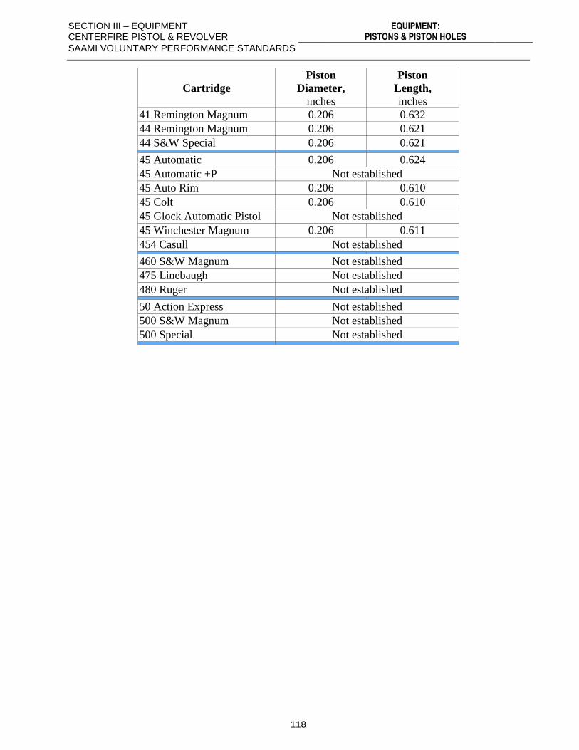
SECTION III – EQUIPMENT CENTERFIRE PISTOL & REVOLVER
EQUIPMENT: PISTONS & PISTON HOLES
SAAMI VOLUNTARY PERFORMANCE STANDARDS
118
Cartridge
Piston
Diameter,
inches
Piston
Length,
inches
41 Remington Magnum 0.206 0.632
44 Remington Magnum 0.206 0.621
44 S&W Special 0.206 0.621
45 Automatic 0.206 0.624
45 Automatic +P Not established
45 Auto Rim 0.206 0.610
45 Colt 0.206 0.610
45 Glock Automatic Pistol Not established
45 Winchester Magnum 0.206 0.611
454 Casull Not established
460 S&W Magnum Not established
475 Linebaugh Not established
480 Ruger Not established
50 Action Express Not established
500 S&W Magnum Not established
500 Special Not established
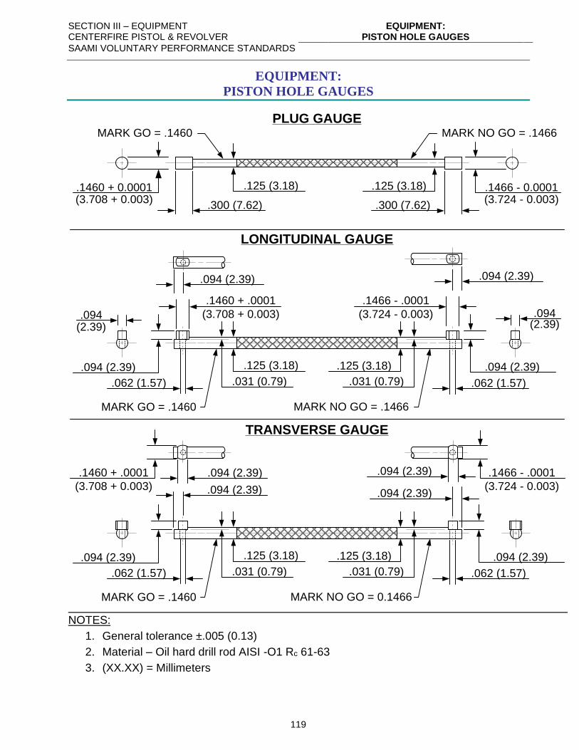
SECTION III – EQUIPMENT CENTERFIRE PISTOL & REVOLVER
EQUIPMENT: PISTON HOLE GAUGES
SAAMI VOLUNTARY PERFORMANCE STANDARDS
119
EQUIPMENT:
PISTON HOLE GAUGES
PLUG GAUGE
.1466 - 0.0001(3.724 - 0.003)
MARK NO GO = .1466
.1460 + 0.0001(3.708 + 0.003)
MARK GO = .1460
.125 (3.18)
LONGITUDINAL GAUGE
MARK GO = .1460
.125 (3.18)
.094(2.39)
.094 (2.39)
`
.062 (1.57)
.300 (7.62) .300 (7.62)
.125 (3.18)
.1460 + .0001
(3.708 + 0.003)
.094 (2.39)
MARK NO GO = .1466
.094(2.39)
.094 (2.39)
.062 (1.57)
.1466 - .0001
(3.724 - 0.003)
.094 (2.39)
.125 (3.18)
.031 (0.79) .031 (0.79)
TRANSVERSE GAUGE
MARK GO = .1460
.125 (3.18).094 (2.39)
`
.062 (1.57)
.1460 + .0001
(3.708 + 0.003) .094 (2.39)
MARK NO GO = 0.1466
.094 (2.39)
.062 (1.57)
.1466 - .0001
(3.724 - 0.003).094 (2.39)
.125 (3.18)
.031 (0.79) .031 (0.79)
.094 (2.39) .094 (2.39)
NOTES:
1. General tolerance ±.005 (0.13)
2. Material – Oil hard drill rod AISI -O1 Rc 61-63
3. (XX.XX) = Millimeters
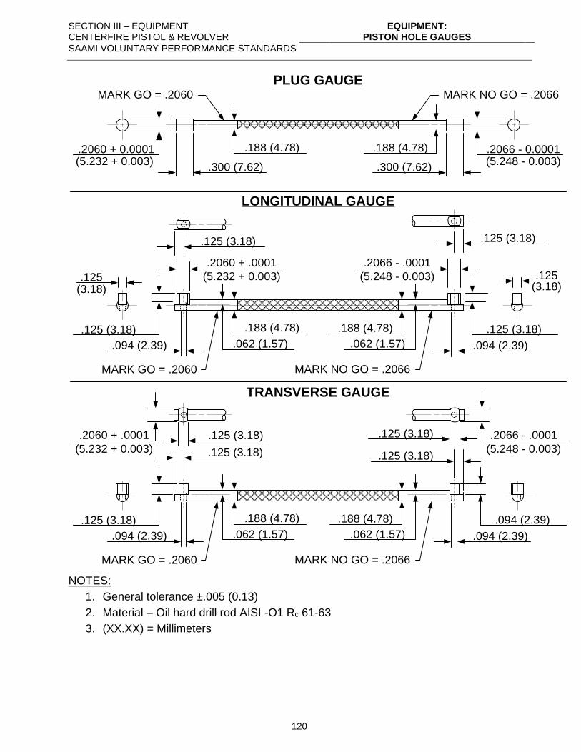
SECTION III – EQUIPMENT CENTERFIRE PISTOL & REVOLVER
EQUIPMENT: PISTON HOLE GAUGES
SAAMI VOLUNTARY PERFORMANCE STANDARDS
120
PLUG GAUGE
.2066 - 0.0001(5.248 - 0.003)
MARK NO GO = .2066
.2060 + 0.0001(5.232 + 0.003)
MARK GO = .2060
.188 (4.78)
LONGITUDINAL GAUGE
MARK GO = .2060
.188 (4.78)
.125(3.18)
.125 (3.18)
`
.094 (2.39)
.300 (7.62) .300 (7.62)
.188 (4.78)
.2060 + .0001
(5.232 + 0.003)
.125 (3.18)
MARK NO GO = .2066
.125(3.18)
.125 (3.18)
.094 (2.39)
.2066 - .0001
(5.248 - 0.003)
.125 (3.18)
.188 (4.78)
.062 (1.57) .062 (1.57)
TRANSVERSE GAUGE
MARK GO = .2060
.188 (4.78).125 (3.18)
`
.094 (2.39)
.2060 + .0001
(5.232 + 0.003) .125 (3.18)
MARK NO GO = .2066
.094 (2.39)
.094 (2.39)
.2066 - .0001
(5.248 - 0.003).125 (3.18)
.188 (4.78)
.062 (1.57) .062 (1.57)
.125 (3.18) .125 (3.18)
NOTES:
1. General tolerance ±.005 (0.13)
2. Material – Oil hard drill rod AISI -O1 Rc 61-63
3. (XX.XX) = Millimeters
SECTION III – EQUIPMENT CENTERFIRE PISTOL & REVOLVER
PISTON OIL - PISTON AND GAS CHECK
SAAMI VOLUNTARY PERFORMANCE STANDARDS
121
PISTON OIL – PISTON AND GAS CHECK
It is recommended that pistons and gas checks (other than those filled with gas check wax) be
lubricated with the following oil:
SAE 30 or equivalent
Viscosity at 210°F (98.9°C) 58 Saybolt seconds universal, minimum
70 Saybolt seconds universal, maximum
The oil should be of non-detergent type.
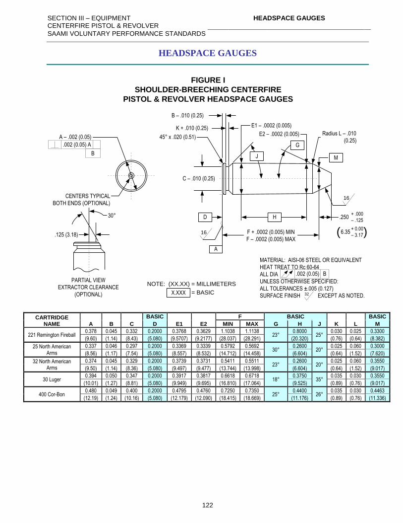
SECTION III – EQUIPMENT CENTERFIRE PISTOL & REVOLVER
HEADSPACE GAUGES
SAAMI VOLUNTARY PERFORMANCE STANDARDS
122
HEADSPACE GAUGES
FIGURE I
SHOULDER-BREECHING CENTERFIRE
PISTOL & REVOLVER HEADSPACE GAUGES
MATERIAL: AISI-06 STEEL OR EQUIVALENT
HEAT TREAT TO Rc 60-64
ALL DIA
UNLESS OTHERWISE SPECIFIED:
ALL TOLERANCES ±.005 (0.127)
SURFACE FINISH EXCEPT AS NOTED.32
.002 (0.05) B
NOTE: (XX.XX) = MILLIMETERS
A – .002 (0.05)
.002 (0.05) A
B
CENTERS TYPICAL
BOTH ENDS (OPTIONAL)
X.XXX = BASIC
A
B – .010 (0.25)
45° x .020 (0.51)
16 F + .0002 (0.005) MIN
F – .0002 (0.005) MAX
HD
E2 – .0002 (0.005)
E1 – .0002 (0.005)K + .010 (0.25)
C – .010 (0.25)
.125 (3.18)
30°
PARTIAL VIEW
EXTRACTOR CLEARANCE
(OPTIONAL)
.250+ .000
– .125
6.35+ 0.00
– 3.17( )
M
Radius L – .010
(0.25)
16
G
J
CARTRIDGE
NAME
BASIC F BASIC BASIC
A B C D E1 E2 MIN MAX G H J K L M
221 Remington Fireball 0.378 0.045 0.332 0.2000 0.3768 0.3629 1.1038 1.1138
23° 0.8000
25° 0.030 0.025 0.3300
(9.60) (1.14) (8.43) (5.080) (9.5707) (9.2177) (28.037) (28.291) (20.320) (0.76) (0.64) (8.382)
25 North American Arms
0.337 0.046 0.297 0.2000 0.3369 0.3339 0.5792 0.5692 30°
0.2600 20°
0.025 0.060 0.3000
(8.56) (1.17) (7.54) (5.080) (8.557) (8.532) (14.712) (14.458) (6.604) (0.64) (1.52) (7.620)
32 North American Arms
0.374 0.045 0.329 0.2000 0.3739 0.3731 0.5411 0.5511 23°
0.2600 20°
0.025 0.060 0.3550
(9.50) (1.14) (8.36) (5.080) (9.497) (9.477) (13.744) (13.998) (6.604) (0.64) (1.52) (9.017)
30 Luger 0.394 0.050 0.347 0.2000 0.3917 0.3817 0.6618 0.6718
18° 0.3750
35° 0.035 0.030 0.3550
(10.01) (1.27) (8.81) (5.080) (9.949) (9.695) (16.810) (17.064) (9.525) (0.89) (0.76) (9.017)
400 Cor-Bon 0.480 0.049 0.400 0.2000 0.4795 0.4760 0.7250 0.7350
25° 0.4400
26° 0.035 0.030 0.4463
(12.19) (1.24) (10.16) (5.080) (12.179) (12.090) (18.415) (18.669) (11.176) (0.89) (0.76) (11.336)
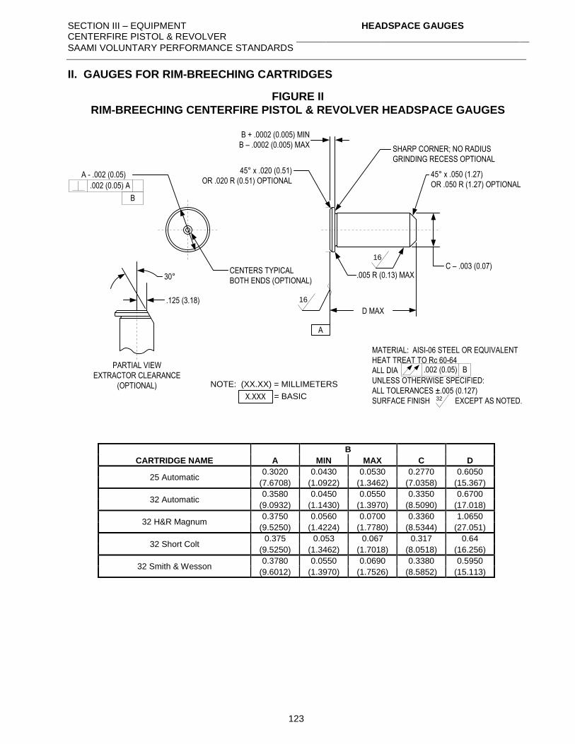
SECTION III – EQUIPMENT CENTERFIRE PISTOL & REVOLVER
HEADSPACE GAUGES
SAAMI VOLUNTARY PERFORMANCE STANDARDS
123
II. GAUGES FOR RIM-BREECHING CARTRIDGES
FIGURE II
RIM-BREECHING CENTERFIRE PISTOL & REVOLVER HEADSPACE GAUGES
SHARP CORNER; NO RADIUS
GRINDING RECESS OPTIONAL
45° x .050 (1.27)
OR .050 R (1.27) OPTIONAL
C – .003 (0.07).005 R (0.13) MAX
A
D MAX
B + .0002 (0.005) MIN
B – .0002 (0.005) MAX
45° x .020 (0.51)
OR .020 R (0.51) OPTIONAL
16
16
MATERIAL: AISI-06 STEEL OR EQUIVALENT
HEAT TREAT TO Rc 60-64
ALL DIA
UNLESS OTHERWISE SPECIFIED:
ALL TOLERANCES ±.005 (0.127)
SURFACE FINISH EXCEPT AS NOTED.32
.002 (0.05) B
NOTE: (XX.XX) = MILLIMETERS
A - .002 (0.05)
.002 (0.05) A
B
CENTERS TYPICAL
BOTH ENDS (OPTIONAL)
.125 (3.18)
30°
PARTIAL VIEW
EXTRACTOR CLEARANCE
(OPTIONAL)
X.XXX = BASIC
CARTRIDGE NAME
B
A MIN MAX C D
25 Automatic 0.3020 0.0430 0.0530 0.2770 0.6050
(7.6708) (1.0922) (1.3462) (7.0358) (15.367)
32 Automatic 0.3580 0.0450 0.0550 0.3350 0.6700
(9.0932) (1.1430) (1.3970) (8.5090) (17.018)
32 H&R Magnum 0.3750 0.0560 0.0700 0.3360 1.0650
(9.5250) (1.4224) (1.7780) (8.5344) (27.051)
32 Short Colt 0.375 0.053 0.067 0.317 0.64
(9.5250) (1.3462) (1.7018) (8.0518) (16.256)
32 Smith & Wesson 0.3780 0.0550 0.0690 0.3380 0.5950
(9.6012) (1.3970) (1.7526) (8.5852) (15.113)
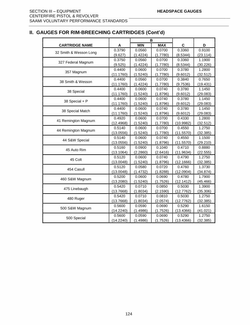
SECTION III – EQUIPMENT CENTERFIRE PISTOL & REVOLVER
HEADSPACE GAUGES
SAAMI VOLUNTARY PERFORMANCE STANDARDS
124
II. GAUGES FOR RIM-BREECHING CARTRIDGES (Cont’d)
CARTRIDGE NAME A
B
C D MIN MAX
32 Smith & Wesson Long 0.3790 0.0560 0.0700 0.3360 0.9100
(9.627) (1.4224) (1.7780) (8.5344) (23.114)
327 Federal Magnum 0.3750 0.0560 0.0700 0.3360 1.1900
(9.525) (1.4224) (1.7780) (8.5344) (30.226)
357 Magnum 0.4400 0.0600 0.0700 0.3780 1.2800
(11.1760) (1.5240) (1.7780) (9.6012) (32.512)
38 Smith & Wesson 0.4400 0.0560 0.0700 0.3840 0.7650
(11.1760) (1.4224) (1.7780) (9.7536) (19.431)
38 Special 0.4400 0.0600 0.0740 0.3780 1.1450
(11.1760) (1.5240) (1.8796) (9.6012) (29.083)
38 Special + P 0.4400 0.0600 0.0740 0.3780 1.1450
(11.1760) (1.5240) (1.8796) (9.6012) (29.083)
38 Special Match 0.4400 0.0600 0.0740 0.3780 1.1450
(11.1760) (1.5240) (1.8796) (9.6012) (29.083)
41 Remington Magnum 0.4920 0.0600 0.0700 0.4330 1.2800
(12.4968) (1.5240) (1.7780) (10.9982) (32.512)
44 Remington Magnum 0.5140 0.0600 0.0700 0.4550 1.2750
(13.0556) (1.5240) (1.7780) (11.5570) (32.385)
44 S&W Special 0.5140 0.0600 0.0740 0.4550 1.1500
(13.0556) (1.5240) (1.8796) (11.5570) (29.210)
45 Auto Rim 0.5160 0.0900 0.1040 0.4710 0.8880
(13.1064) (2.2860) (2.6416) (11.9634) (22.555)
45 Colt 0.5120 0.0600 0.0740 0.4790 1.2750
(13.0048) (1.5240) (1.8796) (12.1666) (32.385)
454 Casull 0.5120 0.0580 0.0720 0.4760 1.3730
(13.0048) (1.4732) (1.8288) (12.0904) (34.874)
460 S&W Magnum 0.5200 0.0600 0.0690 0.4780 1.7900
(13.2080) (1.5240) (1.7526) (12.1412) (45.466)
475 Linebaugh 0.5420 0.0710 0.0850 0.5030 1.3900
(13.7668) (1.8034) (2.1590) (12.7762) (35.306)
480 Ruger 0.5420 0.0710 0.0810 0.5030 1.2750
(13.7668) (1.8034) (2.0574) (12.7762) (32.385)
500 S&W Magnum 0.5600 0.0590 0.0690 0.5290 1.6150
(14.2240) (1.4986) (1.7526) (13.4366) (41.021)
500 Special 0.5600 0.0590 0.0690 0.5290 1.2750
(14.2240) (1.4986) (1.7526) (13.4366) (32.385)
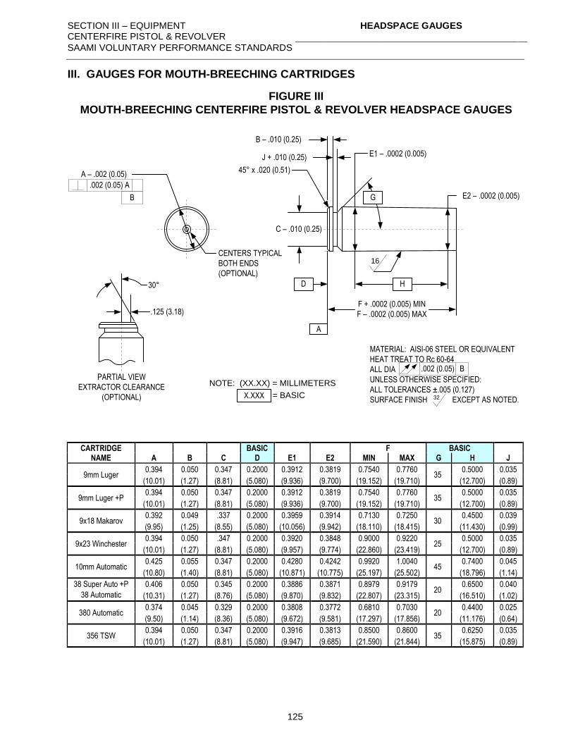
SECTION III – EQUIPMENT CENTERFIRE PISTOL & REVOLVER
HEADSPACE GAUGES
SAAMI VOLUNTARY PERFORMANCE STANDARDS
125
III. GAUGES FOR MOUTH-BREECHING CARTRIDGES
FIGURE III
MOUTH-BREECHING CENTERFIRE PISTOL & REVOLVER HEADSPACE GAUGES
A
B – .010 (0.25)
45° x .020 (0.51)
16
MATERIAL: AISI-06 STEEL OR EQUIVALENT
HEAT TREAT TO Rc 60-64
ALL DIA
UNLESS OTHERWISE SPECIFIED:
ALL TOLERANCES ±.005 (0.127)
SURFACE FINISH EXCEPT AS NOTED.32
.002 (0.05) B
NOTE: (XX.XX) = MILLIMETERS
A – .002 (0.05)
.002 (0.05) A
B
CENTERS TYPICAL
BOTH ENDS
(OPTIONAL)
.125 (3.18)
30°
PARTIAL VIEW
EXTRACTOR CLEARANCE
(OPTIONAL)
F + .0002 (0.005) MIN
F – .0002 (0.005) MAX
HD
E2 – .0002 (0.005)
E1 – .0002 (0.005)J + .010 (0.25)
C – .010 (0.25)
X.XXX = BASIC
G
CARTRIDGE
NAME BASIC F BASIC
A B C D E1 E2 MIN MAX G H J
9mm Luger 0.394 0.050 0.347 0.2000 0.3912 0.3819 0.7540 0.7760
35 0.5000 0.035
(10.01) (1.27) (8.81) (5.080) (9.936) (9.700) (19.152) (19.710) (12.700) (0.89)
9mm Luger +P 0.394 0.050 0.347 0.2000 0.3912 0.3819 0.7540 0.7760
35 0.5000 0.035
(10.01) (1.27) (8.81) (5.080) (9.936) (9.700) (19.152) (19.710) (12.700) (0.89)
9x18 Makarov 0.392 0.049 .337 0.2000 0.3959 0.3914 0.7130 0.7250
30 0.4500 0.039
(9.95) (1.25) (8.55) (5.080) (10.056) (9.942) (18.110) (18.415) (11.430) (0.99)
9x23 Winchester 0.394 0.050 .347 0.2000 0.3920 0.3848 0.9000 0.9220
25 0.5000 0.035
(10.01) (1.27) (8.81) (5.080) (9.957) (9.774) (22.860) (23.419) (12.700) (0.89)
10mm Automatic 0.425 0.055 0.347 0.2000 0.4280 0.4242 0.9920 1.0040
45 0.7400 0.045
(10.80) (1.40) (8.81) (5.080) (10.871) (10.775) (25.197) (25.502) (18.796) (1.14)
38 Super Auto +P 0.406 0.050 0.345 0.2000 0.3886 0.3871 0.8979 0.9179 20
0.6500 0.040
38 Automatic (10.31) (1.27) (8.76) (5.080) (9.870) (9.832) (22.807) (23.315) (16.510) (1.02)
380 Automatic 0.374 0.045 0.329 0.2000 0.3808 0.3772 0.6810 0.7030
20 0.4400 0.025
(9.50) (1.14) (8.36) (5.080) (9.672) (9.581) (17.297) (17.856) (11.176) (0.64)
356 TSW 0.394 0.050 0.347 0.2000 0.3916 0.3813 0.8500 0.8600
35 0.6250 0.035
(10.01) (1.27) (8.81) (5.080) (9.947) (9.685) (21.590) (21.844) (15.875) (0.89)
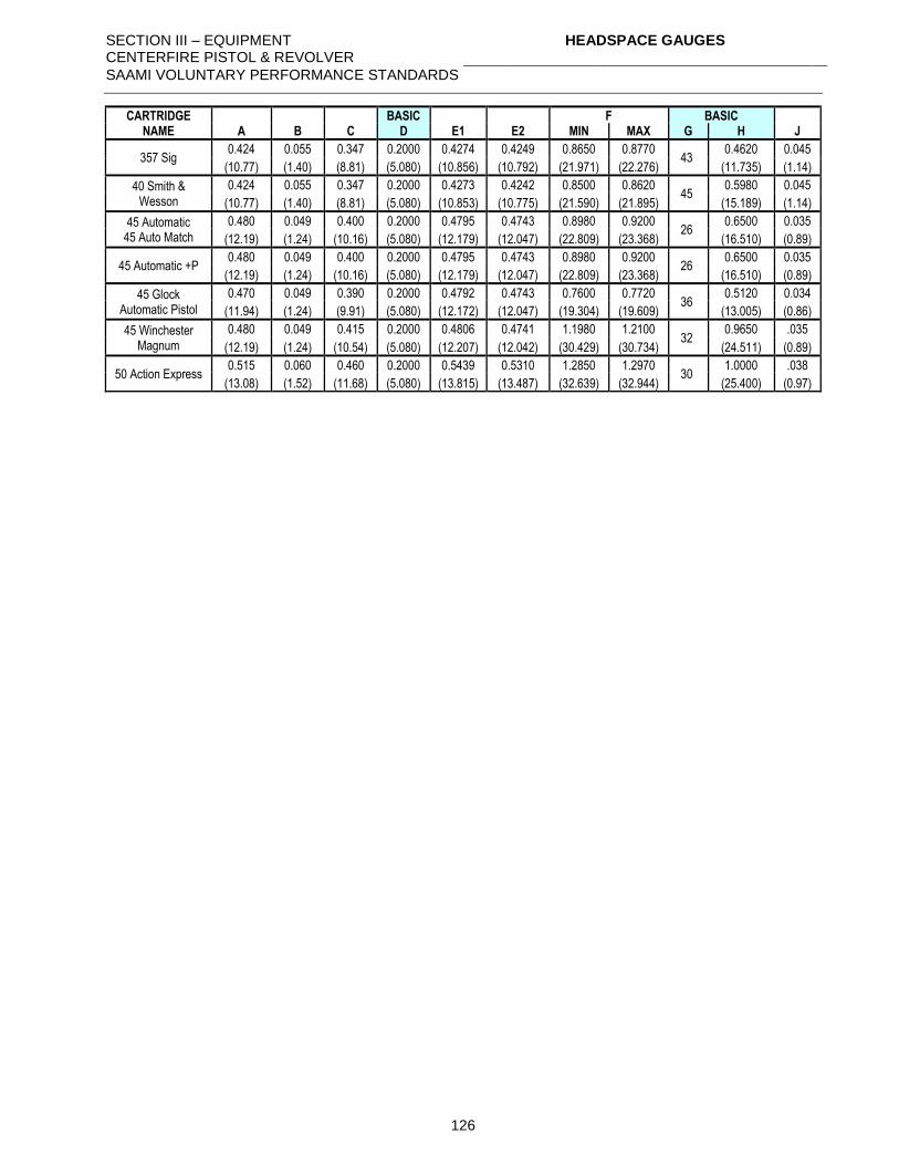
SECTION III – EQUIPMENT CENTERFIRE PISTOL & REVOLVER
HEADSPACE GAUGES
SAAMI VOLUNTARY PERFORMANCE STANDARDS
126
CARTRIDGE NAME
BASIC F BASIC A B C D E1 E2 MIN MAX G H J
357 Sig 0.424 0.055 0.347 0.2000 0.4274 0.4249 0.8650 0.8770
43 0.4620 0.045
(10.77) (1.40) (8.81) (5.080) (10.856) (10.792) (21.971) (22.276) (11.735) (1.14)
40 Smith & Wesson
0.424 0.055 0.347 0.2000 0.4273 0.4242 0.8500 0.8620 45
0.5980 0.045
(10.77) (1.40) (8.81) (5.080) (10.853) (10.775) (21.590) (21.895) (15.189) (1.14)
45 Automatic 45 Auto Match
0.480 0.049 0.400 0.2000 0.4795 0.4743 0.8980 0.9200 26
0.6500 0.035
(12.19) (1.24) (10.16) (5.080) (12.179) (12.047) (22.809) (23.368) (16.510) (0.89)
45 Automatic +P 0.480 0.049 0.400 0.2000 0.4795 0.4743 0.8980 0.9200
26 0.6500 0.035
(12.19) (1.24) (10.16) (5.080) (12.179) (12.047) (22.809) (23.368) (16.510) (0.89)
45 Glock Automatic Pistol
0.470 0.049 0.390 0.2000 0.4792 0.4743 0.7600 0.7720 36
0.5120 0.034
(11.94) (1.24) (9.91) (5.080) (12.172) (12.047) (19.304) (19.609) (13.005) (0.86)
45 Winchester Magnum
0.480 0.049 0.415 0.2000 0.4806 0.4741 1.1980 1.2100 32
0.9650 .035
(12.19) (1.24) (10.54) (5.080) (12.207) (12.042) (30.429) (30.734) (24.511) (0.89)
50 Action Express 0.515 0.060 0.460 0.2000 0.5439 0.5310 1.2850 1.2970
30 1.0000 .038
(13.08) (1.52) (11.68) (5.080) (13.815) (13.487) (32.639) (32.944) (25.400) (0.97)
SECTION III – EQUIPMENT CENTERFIRE PISTOL & REVOLVER
EQUIPMENT: REFERENCE AMMUNITION SUPPLY
SAAMI VOLUNTARY PERFORMANCE STANDARDS
127
EQUIPMENT:
REFERENCE AMMUNITION SUPPLY
NOTE: Refer to Section III – page 130, Supplier Contact Information, for detailed information on
contacting the manufacturers of listed products and the SAAMI Technical Office.
Centerfire pistol and revolver reference ammunition for the verification of ranges, barrels, and other
equipment may be obtained from the manufacturer. Contact the SAAMI Technical Office or see
website for detailed information.
The SAAMI Technical Office maintains current assessment data. SAAMI policy does not allow the
release of assessment values by the manufacturer of reference ammunition. All assessments are to
be supplied by the SAAMI Technical Office.
SECTION III – EQUIPMENT CENTERFIRE PISTOL & REVOLVER
EQUIPMENT: REFERENCE AMMUNITION ORDER PROCEDURE
SAAMI VOLUNTARY PERFORMANCE STANDARDS
128
EQUIPMENT:
REFERENCE AMMUNITION ORDER PROCEDURE
Each order should contain the following information, in the following order:
1. Number of rounds desired. (See NOTE, below.)
2. Appropriate order symbol, when given.
3. Designation “SAAMI Reference Ammunition”.
4. Cartridge name.
5. SAAMI lot number. (Current lot numbers are given on latest assessment value sheets
issued by the SAAMI Technical Office.)
EXAMPLE:
200 rounds, Order symbol SA9LP
SAAMI Reference Ammunition
9mm Luger
SAAMI Lot 9MM-115-16WW
NOTE: Recommended maximum order = 200 rounds. If an individual user has requirements for
larger quantities, refer to Section II - page 95.
Manufacturers of SAAMI reference ammunition may limit the order quantities honored to the
recommended maximum in order to prevent premature consumption of a lot.
It is up to the discretion of the manufacturer to produce lots of sufficient size to reasonably provide a
five-year supply.
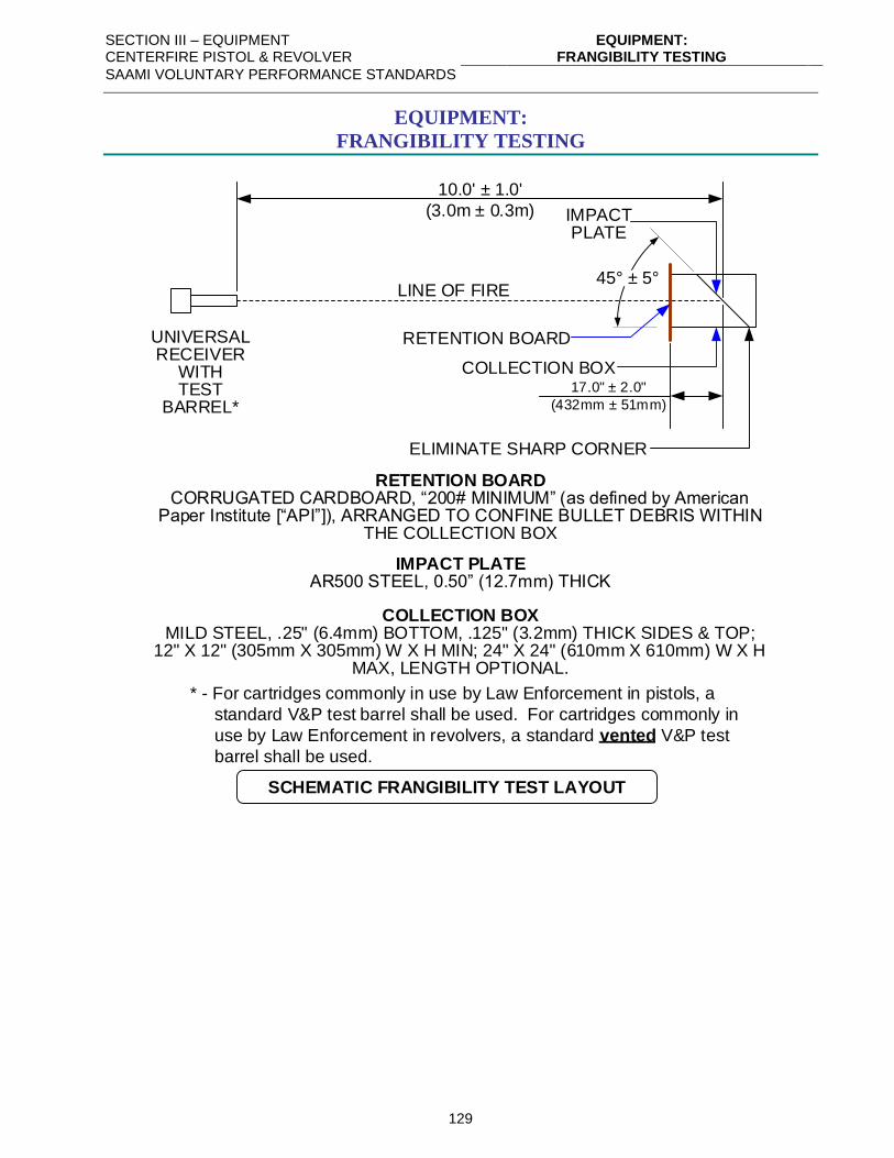
SECTION III – EQUIPMENT CENTERFIRE PISTOL & REVOLVER
EQUIPMENT: FRANGIBILITY TESTING
SAAMI VOLUNTARY PERFORMANCE STANDARDS
129
EQUIPMENT:
FRANGIBILITY TESTING
IMPACT PLATEAR500 STEEL, 0.50” (12.7mm) THICK
10.0' ± 1.0'
(3.0m ± 0.3m)
LINE OF FIRE
UNIVERSALRECEIVER
WITHTEST
BARREL*
SCHEMATIC FRANGIBILITY TEST LAYOUT
RETENTION BOARDCORRUGATED CARDBOARD, “200# MINIMUM” (as defined by American
Paper Institute [“API”]), ARRANGED TO CONFINE BULLET DEBRIS WITHIN THE COLLECTION BOX
* - For cartridges commonly in use by Law Enforcement in pistols, a
standard V&P test barrel shall be used. For cartridges commonly in
use by Law Enforcement in revolvers, a standard vented V&P test
barrel shall be used.
COLLECTION BOXMILD STEEL, .25" (6.4mm) BOTTOM, .125" (3.2mm) THICK SIDES & TOP;
12" X 12" (305mm X 305mm) W X H MIN; 24" X 24" (610mm X 610mm) W X H MAX, LENGTH OPTIONAL.
45° ± 5°
17.0" ± 2.0"
(432mm ± 51mm)
IMPACTPLATE
COLLECTION BOX
RETENTION BOARD
ELIMINATE SHARP CORNER
SECTION III – EQUIPMENT CENTERFIRE PISTOL & REVOLVER
SUPPLIER CONTACT INFORMATION
SAAMI VOLUNTARY PERFORMANCE STANDARDS
130
SUPPLIER CONTACT INFORMATION
Contact the SAAMI Technical Office using the information below or visit www.saami.org for a
current list of supplier contact information.
SAAMI Technical Office ....................................................................................... SAAMI Information
11 Mile Hill Road
Newtown, CT 06470
Phone: 203-426-4358
E-mail:
Website: www.saami.org
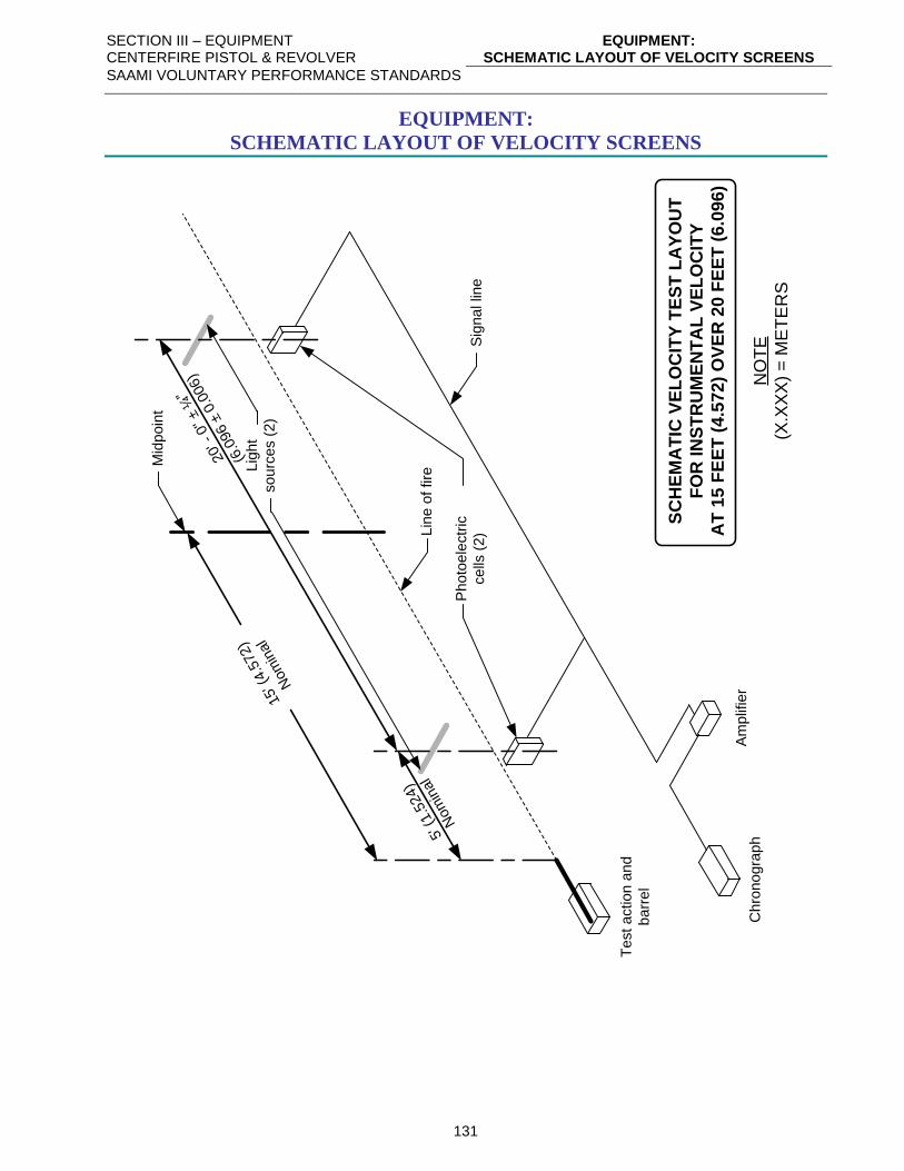
SECTION III – EQUIPMENT CENTERFIRE PISTOL & REVOLVER
EQUIPMENT: SCHEMATIC LAYOUT OF VELOCITY SCREENS
SAAMI VOLUNTARY PERFORMANCE STANDARDS
131
EQUIPMENT:
SCHEMATIC LAYOUT OF VELOCITY SCREENS
SC
HE
MA
TIC
VE
LO
CIT
Y T
ES
T L
AY
OU
T
FO
R IN
ST
RU
ME
NT
AL
VE
LO
CIT
Y
AT
15
FE
ET
(4.5
72
) O
VE
R 2
0 F
EE
T (
6.0
96
)
NO
TE
(X.X
XX
) =
ME
TE
RS
Sig
na
l lin
e
Lin
e o
f fire
Ch
ron
og
rap
h
Ph
oto
ele
ctr
ic
ce
lls (
2)
20' -
0" ± ¼
”
(6.0
96 ±
0.0
06)
Mid
po
int
Lig
ht
so
urc
es (
2)
15' (
4.5
72)
Nom
inal
5' (
1.5
24)
Nom
inal
Te
st a
ctio
n a
nd
ba
rre
l
Am
plif
ier
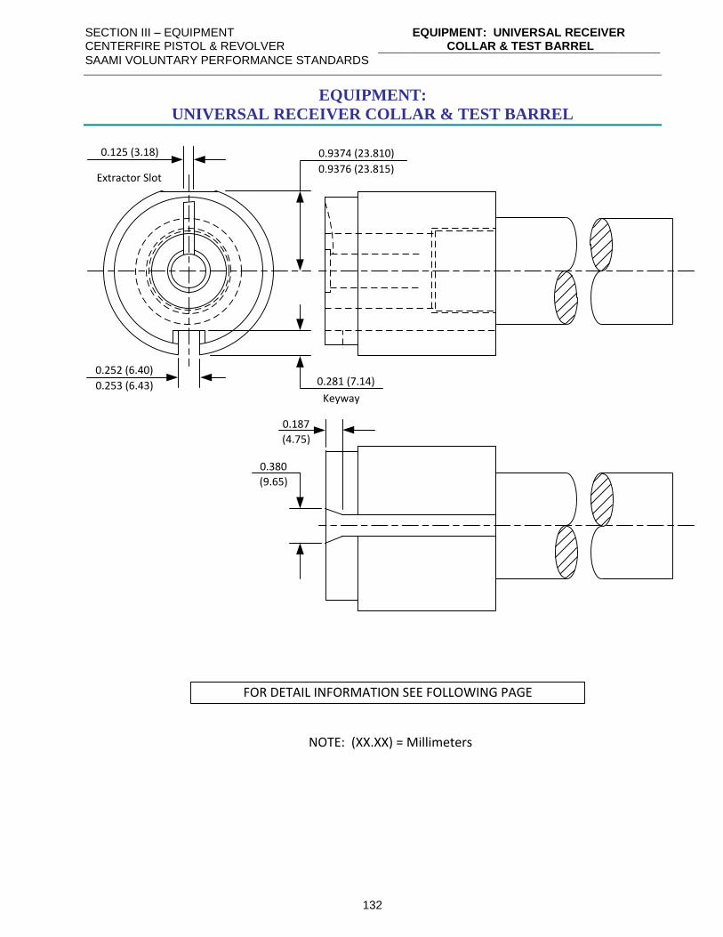
SECTION III – EQUIPMENT CENTERFIRE PISTOL & REVOLVER
EQUIPMENT: UNIVERSAL RECEIVER COLLAR & TEST BARREL
SAAMI VOLUNTARY PERFORMANCE STANDARDS
132
EQUIPMENT:
UNIVERSAL RECEIVER COLLAR & TEST BARREL
0.252 (6.40)
0.253 (6.43)
0.9374 (23.810)
0.9376 (23.815)
0.125 (3.18)
Extractor Slot
0.281 (7.14)
Keyway
0.380
(9.65)
0.187
(4.75)
NOTE: (XX.XX) = Millimeters
FOR DETAIL INFORMATION SEE FOLLOWING PAGE
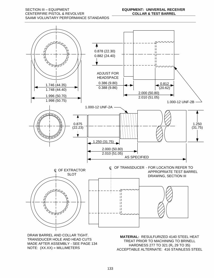
SECTION III – EQUIPMENT CENTERFIRE PISTOL & REVOLVER
EQUIPMENT: UNIVERSAL RECEIVER COLLAR & TEST BARREL
SAAMI VOLUNTARY PERFORMANCE STANDARDS
133
MATERIAL: RESULFURIZED 4140 STEEL HEAT
TREAT PRIOR TO MACHINING TO BRINELL
HARDNESS 277 TO 321 (Rc 29 TO 35)
ACCEPTABLE ALTERNATE: 416 STAINLESS STEEL
1.746 (44.35)
1.748 (44.40)
0.878 (22.30)
0.882 (24.40)
1.996 (50.70)
1.998 (50.75)
0.386 (9.80)
0.388 (9.86)
2.000 (50.80)
2.010 (51.05)
0.812(20.62)
ADJUST FOR
HEADSPACE
1.000-12 UNF-2B
1.250(31.75)
1.250 (31.75)
1.000-12 UNF-2A
0.875(22.23)
2.000 (50.80)
2.010 (51.05)AS SPECIFIED
CL OF EXTRACTOR
SLOT
CL OF TRANSDUCER - FOR LOCATION REFER TO
APPROPRIATE TEST BARREL
DRAWING, SECTION III
DRAW BARREL AND COLLAR TIGHT.
TRANSDUCER HOLE AND HEAD CUTS
MADE AFTER ASSEMBLY - SEE PAGE 134
NOTE: (XX.XX) = MILLIMETERS
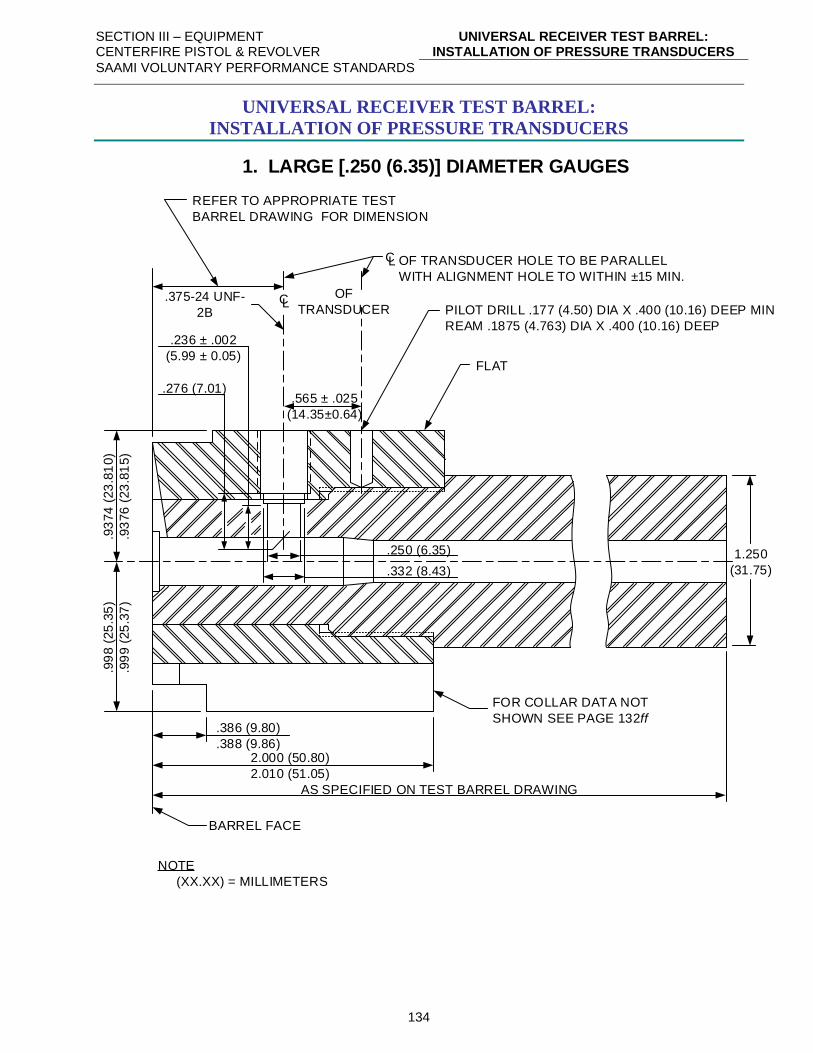
SECTION III – EQUIPMENT CENTERFIRE PISTOL & REVOLVER
UNIVERSAL RECEIVER TEST BARREL: INSTALLATION OF PRESSURE TRANSDUCERS
SAAMI VOLUNTARY PERFORMANCE STANDARDS
134
UNIVERSAL RECEIVER TEST BARREL:
INSTALLATION OF PRESSURE TRANSDUCERS
.250 (6.35)
.332 (8.43)
.276 (7.01)
.236 ± .002
(5.99 ± 0.05)
.375-24 UNF-
2B
REFER TO APPROPRIATE TEST
BARREL DRAWING FOR DIMENSION
.565 ± .025
(14.35±0.64)
LCOF
TRANSDUCER
LC OF TRANSDUCER HOLE TO BE PARALLEL
WITH ALIGNMENT HOLE TO WITHIN ±15 MIN.
PILOT DRILL .177 (4.50) DIA X .400 (10.16) DEEP MIN
REAM .1875 (4.763) DIA X .400 (10.16) DEEP
FLAT
.93
74
(23
.81
0)
.93
76
(23
.81
5)
.99
8 (
25
.35
)
.99
9 (
25
.37
)
.386 (9.80)
.388 (9.86)2.000 (50.80)
2.010 (51.05)
AS SPECIFIED ON TEST BARREL DRAWING
BARREL FACE
FOR COLLAR DATA NOT
SHOWN SEE PAGE 132ff
1.250
(31.75)
NOTE
(XX.XX) = MILLIMETERS
1. LARGE [.250 (6.35)] DIAMETER GAUGES
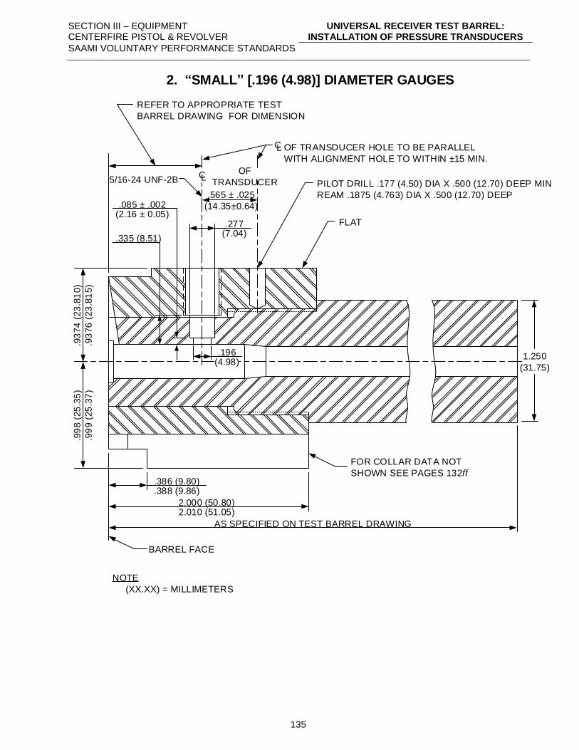
SECTION III – EQUIPMENT CENTERFIRE PISTOL & REVOLVER
UNIVERSAL RECEIVER TEST BARREL: INSTALLATION OF PRESSURE TRANSDUCERS
SAAMI VOLUNTARY PERFORMANCE STANDARDS
135
.335 (8.51)
REFER TO APPROPRIATE TEST
BARREL DRAWING FOR DIMENSION
.565 ± .025
(14.35±0.64)
LCOF
TRANSDUCER
LC OF TRANSDUCER HOLE TO BE PARALLEL
WITH ALIGNMENT HOLE TO WITHIN ±15 MIN.
FLAT
.93
74
(23
.81
0)
.93
76
(23
.81
5)
.99
8 (
25
.35
)
.99
9 (
25
.37
)
.386 (9.80)
.388 (9.86)
2.000 (50.80)2.010 (51.05)
AS SPECIFIED ON TEST BARREL DRAWING
BARREL FACE
FOR COLLAR DATA NOT
SHOWN SEE PAGES 132ff
1.250
(31.75)
NOTE
(XX.XX) = MILLIMETERS
.085 ± .002(2.16 ± 0.05)
.196(4.98)
PILOT DRILL .177 (4.50) DIA X .500 (12.70) DEEP MIN
REAM .1875 (4.763) DIA X .500 (12.70) DEEP
5/16-24 UNF-2B
.277(7.04)
2. SMALL [.196 (4.98)] DIAMETER GAUGES
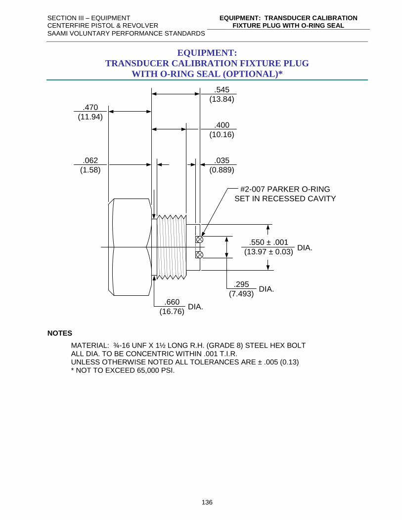
SECTION III – EQUIPMENT CENTERFIRE PISTOL & REVOLVER
EQUIPMENT: TRANSDUCER CALIBRATION FIXTURE PLUG WITH O-RING SEAL
SAAMI VOLUNTARY PERFORMANCE STANDARDS
136
EQUIPMENT:
TRANSDUCER CALIBRATION FIXTURE PLUG
WITH O-RING SEAL (OPTIONAL)*
.295
(7.493)DIA.
.550 ± .001
(13.97 ± 0.03)DIA.
.660
(16.76)DIA.
.062
(1.58)
.035
(0.889)
#2-007 PARKER O-RING
SET IN RECESSED CAVITY
.400
(10.16)
.545
(13.84).470
(11.94)
NOTES
MATERIAL: ¾-16 UNF X 1½ LONG R.H. (GRADE 8) STEEL HEX BOLT ALL DIA. TO BE CONCENTRIC WITHIN .001 T.I.R. UNLESS OTHERWISE NOTED ALL TOLERANCES ARE ± .005 (0.13) * NOT TO EXCEED 65,000 PSI.
SECTION III – EQUIPMENT CENTERFIRE PISTOL & REVOLVER
TRANSDUCER LOCATION CRITERIA
SAAMI VOLUNTARY PERFORMANCE STANDARDS
137
TRANSDUCER LOCATION CRITERIA
I. Transducer Location
The following criteria for transducer location positioning should be followed when designing
new cartridges. In those cases where following the criteria will cause the transducer to be
located over current or projected bullet heel locations, case cannelures, or other undesirable
areas, the best alternate location should be chosen. In general, the location should be as close
to the bullet heel as practical.
A. Straight-walled Cartridge Cases
The centerline of the transducer shall be located behind the heel of the bullet by an
amount equal to one-half the transducer diameter plus 0.005” – 0.010” (0.13 mm – 0.25
mm). This criterion applies to both large diameter [0.250” (6.35 mm)] and small
diameter [0.194” (4.93 mm)] transducers.
B. Bottleneck Cartridge Cases
The centerline of the transducer shall be located behind the shell case shoulder
intersection by an amount of 0.175” (4.44 mm) for large diameter [0.250” (6.35 mm)]
transducers and by 0.150” (3.80 mm) for small diameter [0.194” (4.93 mm)] transducers.
II. Transducer Diameter
A. Large Diameter [0.250” (6.35 mm)] Transducers
This size is selected when the chamber diameter at transducer centerline is equal to or
greater than 0.350” (8.89 mm).
B. Small Diameter [0.194” (4.93 mm)] Transducers
This size is selected when the chamber diameter at transducer centerline is less than
0.350” (8.89 mm).
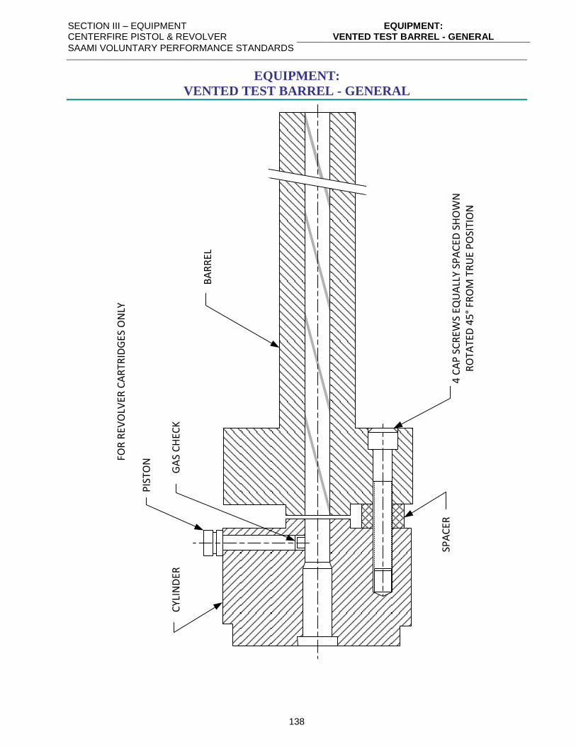
SECTION III – EQUIPMENT CENTERFIRE PISTOL & REVOLVER
EQUIPMENT: VENTED TEST BARREL - GENERAL
SAAMI VOLUNTARY PERFORMANCE STANDARDS
138
EQUIPMENT:
VENTED TEST BARREL - GENERAL
PIS
TON
GA
S C
HEC
KC
YLIN
DER
SPA
CER
4 C
AP
SC
REW
S EQ
UA
LLY
SPA
CED
SH
OW
N
RO
TATE
D 4
5°
FRO
M T
RU
E P
OSI
TIO
N
FOR
REV
OLV
ER C
AR
TRID
GES
ON
LY
BA
RR
EL
SECTION III – EQUIPMENT CENTERFIRE PISTOL & REVOLVER
STANDARD V&P TEST BARRELS - GENERAL: PROCEDURES FOR DIMENSIONING CHAMBERS
SAAMI VOLUNTARY PERFORMANCE STANDARDS
139
STANDARD V&P TEST BARRELS - GENERAL:
PROCEDURES FOR DIMENSIONING CHAMBERS
Chamber and bore dimensions of velocity and pressure test barrels shall conform to the dimensions
of the chamber and bore at Maximum Material Condition (MMC) for each cartridge as originally
introduced. Fabrication tolerances, however, are much reduced.
It is recognized that changes may be made to cartridge or chamber dimensions in order to improve
the velocity-pressure relationship, accuracy or functioning in pistols or revolvers as production
experience indicates. However, none of these changes should be of such nature that they would
cause a significant increase in pressure level of a given lot of ammunition.
No changes shall be made to velocity and pressure barrel dimensions which would result in a
reduction of the recorded pressure level of any given lot of ammunition. This would result in the
possibility of future lots of ammunition being loaded with increased powder charges, which would
cause increased pressure in existing pistols and revolvers.
Production barrels may be adapted for velocity and pressure testing provided that they conform to all
dimensions shown on the appropriate test barrel drawing.
SECTION III – EQUIPMENT CENTERFIRE PISTOL & REVOLVER
STANDARD V&P TEST BARRELS - GENERAL: PROCEDURES FOR MEASURING BARREL LENGTH
SAAMI VOLUNTARY PERFORMANCE STANDARDS
140
STANDARD V&P TEST BARRELS - GENERAL:
PROCEDURES FOR MEASURING BARREL LENGTH
Centerfire pistol and revolver solid test barrels are measured by inserting a rod down the bore from
the muzzle until it touches the breech face with the action closed and the firing pin retracted.
Vented test barrels for revolver ammunition are measured by inserting a rod down the bore from the
muzzle to the rear end of the barrel.
A stop collar or other means is utilized to mark the point on the rod adjacent to the most forward part
of the barrel or the bottom of the counterbore in barrels having a counterbore recess at the muzzle.
The rod is removed and the distance from the mark to the end of the rod is measured. This
measurement is recorded as the barrel length.
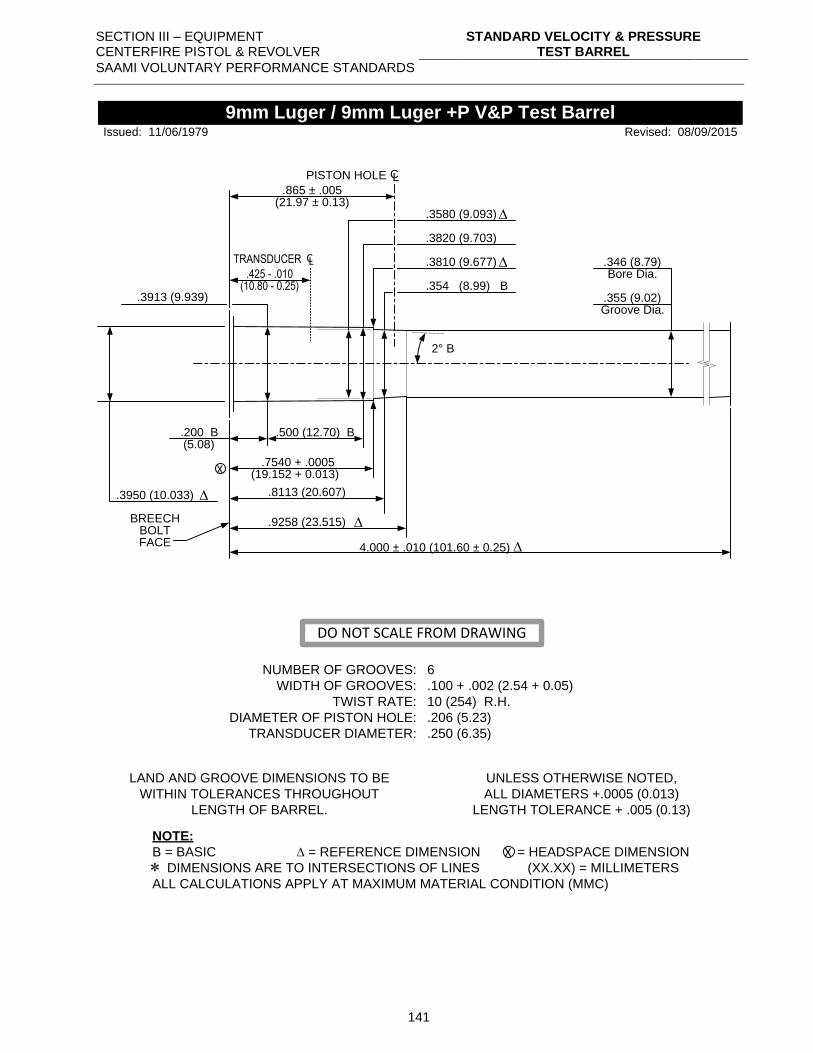
SECTION III – EQUIPMENT CENTERFIRE PISTOL & REVOLVER
STANDARD VELOCITY & PRESSURE TEST BARREL
SAAMI VOLUNTARY PERFORMANCE STANDARDS
141
.3913 (9.939)
.865 ± .005(21.97 ± 0.13)
PISTON HOLE CL
.3580 (9.093)
.3820 (9.703)
.3810 (9.677)
2° B
.500 (12.70) B.200 B(5.08)
.7540 + .0005
.8113 (20.607)
.9258 (23.515)
X
.346 (8.79)
.355 (9.02)
Bore Dia.
Groove Dia.
.3950 (10.033)
NUMBER OF GROOVES:
WIDTH OF GROOVES:
TWIST RATE:
DIAMETER OF PISTON HOLE:
TRANSDUCER DIAMETER:
6
.100 + .002 (2.54 + 0.05)
10 (254) R.H.
.206 (5.23)
.250 (6.35)
LAND AND GROOVE DIMENSIONS TO BE
WITHIN TOLERANCES THROUGHOUT
LENGTH OF BARREL.
UNLESS OTHERWISE NOTED,
ALL DIAMETERS +.0005 (0.013)
LENGTH TOLERANCE + .005 (0.13)
NOTE:
B = BASIC = REFERENCE DIMENSION = HEADSPACE DIMENSION
DIMENSIONS ARE TO INTERSECTIONS OF LINES (XX.XX) = MILLIMETERS
ALL CALCULATIONS APPLY AT MAXIMUM MATERIAL CONDITION (MMC)
X
9mm Luger / 9mm Luger +P V&P Test Barrel
BREECHBOLTFACE
Revised: 08/09/2015
.354 (8.99) B
(19.152 + 0.013)
Issued: 11/06/1979
DO NOT SCALE FROM DRAWING
.425 - .010
TRANSDUCER CL
(10.80 - 0.25)
4.000 ± .010 (101.60 ± 0.25)
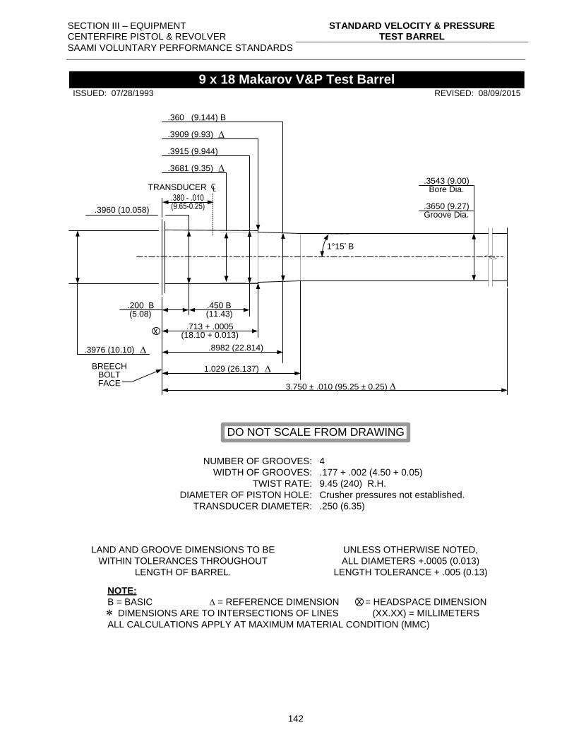
SECTION III – EQUIPMENT CENTERFIRE PISTOL & REVOLVER
STANDARD VELOCITY & PRESSURE TEST BARREL
SAAMI VOLUNTARY PERFORMANCE STANDARDS
142
.3960 (10.058)
.3915 (9.944)
1°15’ B
.450 B.200 B(5.08)
.713 + .0005
.8982 (22.814)
1.029 (26.137)
X
.3543 (9.00)
.3650 (9.27)
Bore Dia.
Groove Dia.
.3976 (10.10)
NUMBER OF GROOVES:
WIDTH OF GROOVES:
TWIST RATE:
DIAMETER OF PISTON HOLE:
TRANSDUCER DIAMETER:
4
.177 + .002 (4.50 + 0.05)
9.45 (240) R.H.
Crusher pressures not established.
.250 (6.35)
LAND AND GROOVE DIMENSIONS TO BE
WITHIN TOLERANCES THROUGHOUT
LENGTH OF BARREL.
UNLESS OTHERWISE NOTED,
ALL DIAMETERS +.0005 (0.013)
LENGTH TOLERANCE + .005 (0.13)
NOTE:
B = BASIC = REFERENCE DIMENSION = HEADSPACE DIMENSION
DIMENSIONS ARE TO INTERSECTIONS OF LINES (XX.XX) = MILLIMETERS
ALL CALCULATIONS APPLY AT MAXIMUM MATERIAL CONDITION (MMC)
X
9 x 18 Makarov V&P Test Barrel
BREECHBOLTFACE
REVISED: 08/09/2015
.360 (9.144) B
(18.10 + 0.013)
.3681 (9.35)
.3909 (9.93)
(11.43)
ISSUED: 07/28/1993
DO NOT SCALE FROM DRAWING
.380 - .010
TRANSDUCER CL
(9.65-0.25)
3.750 ± .010 (95.25 ± 0.25)
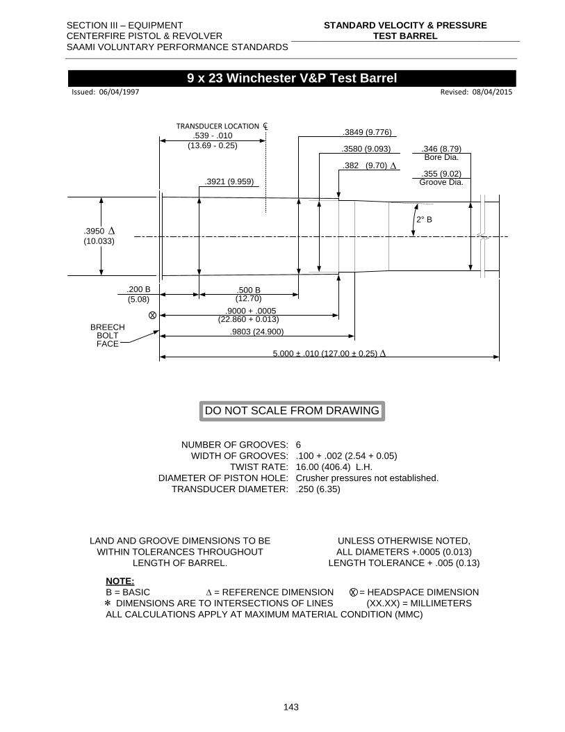
SECTION III – EQUIPMENT CENTERFIRE PISTOL & REVOLVER
STANDARD VELOCITY & PRESSURE TEST BARREL
SAAMI VOLUNTARY PERFORMANCE STANDARDS
143
.3921 (9.959)
.3849 (9.776)
2° B
.500 B.200 B
(5.08)
.9000 + .0005
.9803 (24.900)
X
.346 (8.79)
.355 (9.02)
Bore Dia.
Groove Dia.
.3950
(10.033)
NUMBER OF GROOVES:
WIDTH OF GROOVES:
TWIST RATE:
DIAMETER OF PISTON HOLE:
TRANSDUCER DIAMETER:
6
.100 + .002 (2.54 + 0.05)
16.00 (406.4) L.H.
Crusher pressures not established.
.250 (6.35)
LAND AND GROOVE DIMENSIONS TO BE
WITHIN TOLERANCES THROUGHOUT
LENGTH OF BARREL.
UNLESS OTHERWISE NOTED,
ALL DIAMETERS +.0005 (0.013)
LENGTH TOLERANCE + .005 (0.13)
NOTE:
B = BASIC = REFERENCE DIMENSION = HEADSPACE DIMENSION
DIMENSIONS ARE TO INTERSECTIONS OF LINES (XX.XX) = MILLIMETERS
ALL CALCULATIONS APPLY AT MAXIMUM MATERIAL CONDITION (MMC)
X
9 x 23 Winchester V&P Test Barrel
BREECHBOLTFACE
Revised: 08/04/2015
.3580 (9.093)
(22.860 + 0.013)
.382 (9.70)
(12.70)
Issued: 06/04/1997
DO NOT SCALE FROM DRAWING
.539 - .010
(13.69 - 0.25)
TRANSDUCER LOCATION CL
5.000 ± .010 (127.00 ± 0.25)
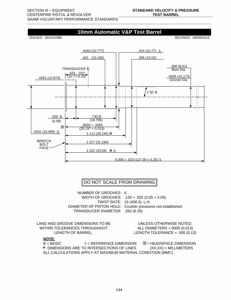
SECTION III – EQUIPMENT CENTERFIRE PISTOL & REVOLVER
STANDARD VELOCITY & PRESSURE TEST BARREL
SAAMI VOLUNTARY PERFORMANCE STANDARDS
144
.4281 (10.874)
.4243 (10.777)
1°30’ B
.740 B.200 B
(5.08)
.9920 + .0005
1.112 (28.245)
1.227 (31.166)
X
.390 (9.91)
.4005 (10.173)
Bore Dia.
Groove Dia.
.4291 (10.899)
NUMBER OF GROOVES:
WIDTH OF GROOVES:
TWIST RATE:
DIAMETER OF PISTON HOLE:
TRANSDUCER DIAMETER:
6
.120 + .002 (3.05 + 0.05)
16 (406.4) L.H.
Crusher pressures not established.
.250 (6.35)
LAND AND GROOVE DIMENSIONS TO BE
WITHIN TOLERANCES THROUGHOUT
LENGTH OF BARREL.
UNLESS OTHERWISE NOTED,
ALL DIAMETERS +.0005 (0.013)
LENGTH TOLERANCE + .005 (0.13)
NOTE:
B = BASIC = REFERENCE DIMENSION = HEADSPACE DIMENSION
DIMENSIONS ARE TO INTERSECTIONS OF LINES (XX.XX) = MILLIMETERS
ALL CALCULATIONS APPLY AT MAXIMUM MATERIAL CONDITION (MMC)
X
10mm Automatic V&P Test Barrel
BREECHBOLTFACE
REVISED: 08/09/2015
.395 (10.03)
(25.197 + 0.013)
.424 (10.77)
.401 (10.185)
1.322 (33.58)
(18.796)
ISSUED: 04/10/1989
DO NOT SCALE FROM DRAWING
.424 - .010
TRANSDUCER CL
(10.77-0.25)
5.000 ± .010 (127.00 ± 0.25)
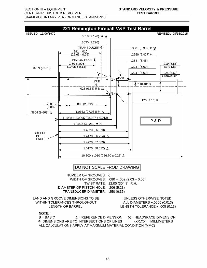
SECTION III – EQUIPMENT CENTERFIRE PISTOL & REVOLVER
STANDARD VELOCITY & PRESSURE TEST BARREL
SAAMI VOLUNTARY PERFORMANCE STANDARDS
145
.3769 (9.573)
.750 ± .005(19.05 ± 0.13)
PISTON HOLE CL
.3630 (9.220)
.3618 (9.190)
.330 (8.38) B X
.2550 (6.477)
.254 (6.45)
.224 (5.69)
.224 (5.69)
3°10’48” B
.800 (20.32) B.200 B(5.08)
1.0663 (27.084)
1.1038 + 0.0005 (28.037 + 0.013)
1.1922 (30.282)
1.4320 (36.373)
1.4470 (36.754)
1.4720 (37.389)
1.5170 (38.532)
X
.219 (5.56)
.224 (5.69)
Bore Dia.
Groove Dia.45°B
23°B
.3804 (9.662)
.125 (3.18) R
.025 (0.64) R Max.
NUMBER OF GROOVES:
WIDTH OF GROOVES:
TWIST RATE:
DIAMETER OF PISTON HOLE:
TRANSDUCER DIAMETER:
6
.080 + .002 (2.03 + 0.05)
12.00 (304.8) R.H.
.206 (5.23)
.250 (6.35)
LAND AND GROOVE DIMENSIONS TO BE
WITHIN TOLERANCES THROUGHOUT
LENGTH OF BARREL.
UNLESS OTHERWISE NOTED,
ALL DIAMETERS +.0005 (0.013)
LENGTH TOLERANCE + .005 (0.13)
NOTE:
B = BASIC = REFERENCE DIMENSION = HEADSPACE DIMENSION
DIMENSIONS ARE TO INTERSECTIONS OF LINES (XX.XX) = MILLIMETERS
ALL CALCULATIONS APPLY AT MAXIMUM MATERIAL CONDITION (MMC)
X
221 Remington Fireball V&P Test Barrel
BREECHBOLTFACE
REVISED: 08/15/2015ISSUED: 11/06/1979
.891 - .010
TRANSDUCER CL
(22.63 - 0.25)
DO NOT SCALE FROM DRAWING
P & R
10.500 ± .010 (266.70 ± 0.25)
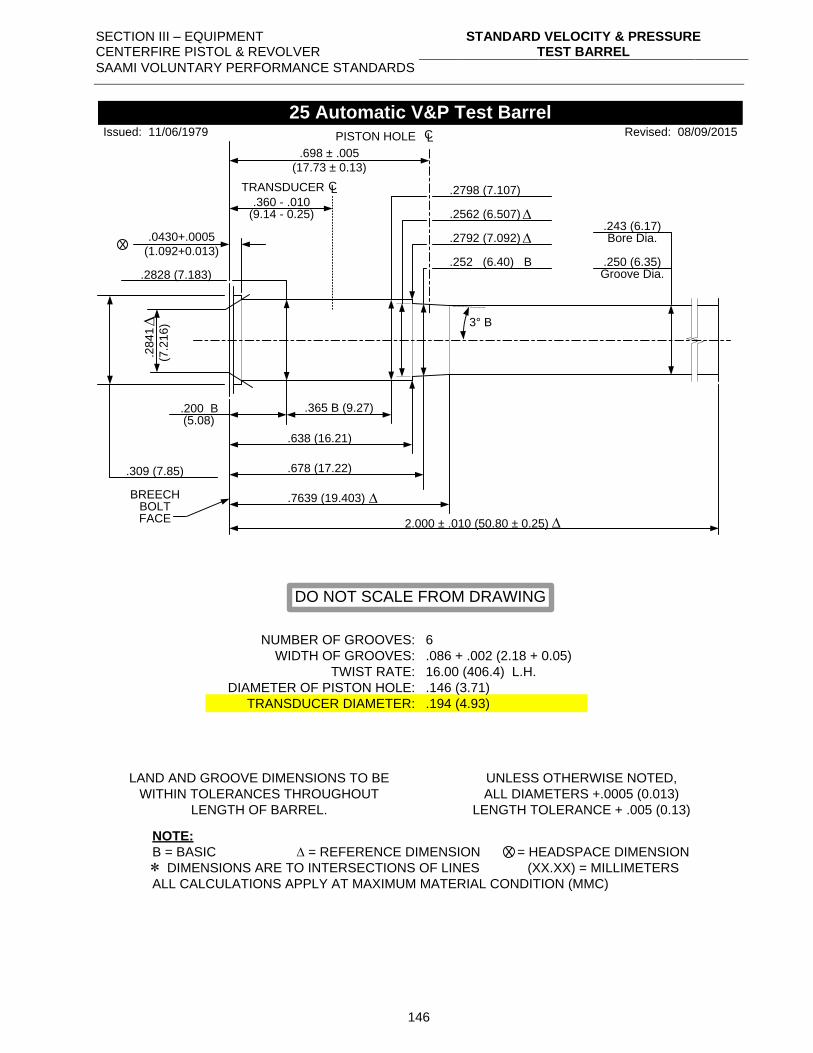
SECTION III – EQUIPMENT CENTERFIRE PISTOL & REVOLVER
STANDARD VELOCITY & PRESSURE TEST BARREL
SAAMI VOLUNTARY PERFORMANCE STANDARDS
146
.2828 (7.183)
.698 ± .005
(17.73 ± 0.13)
PISTON HOLE CL
.2562 (6.507)
.2792 (7.092)
3° B
.365 B (9.27).200 B(5.08)
.638 (16.21)
.678 (17.22)
.7639 (19.403)
X
.243 (6.17)
.250 (6.35)
Bore Dia.
Groove Dia.
.309 (7.85)
NUMBER OF GROOVES:
WIDTH OF GROOVES:
TWIST RATE:
DIAMETER OF PISTON HOLE:
TRANSDUCER DIAMETER:
6
.086 + .002 (2.18 + 0.05)
16.00 (406.4) L.H.
.146 (3.71)
.194 (4.93)
LAND AND GROOVE DIMENSIONS TO BE
WITHIN TOLERANCES THROUGHOUT
LENGTH OF BARREL.
UNLESS OTHERWISE NOTED,
ALL DIAMETERS +.0005 (0.013)
LENGTH TOLERANCE + .005 (0.13)
NOTE:
B = BASIC = REFERENCE DIMENSION = HEADSPACE DIMENSION
DIMENSIONS ARE TO INTERSECTIONS OF LINES (XX.XX) = MILLIMETERS
ALL CALCULATIONS APPLY AT MAXIMUM MATERIAL CONDITION (MMC)
X
25 Automatic V&P Test Barrel
BREECHBOLTFACE
Revised: 08/09/2015
.252 (6.40) B
Issued: 11/06/1979
.2
84
1
(7.2
16
)
.2798 (7.107)
.0430+.0005
(1.092+0.013)
DO NOT SCALE FROM DRAWING
.360 - .010
TRANSDUCER CL
(9.14 - 0.25)
2.000 ± .010 (50.80 ± 0.25)
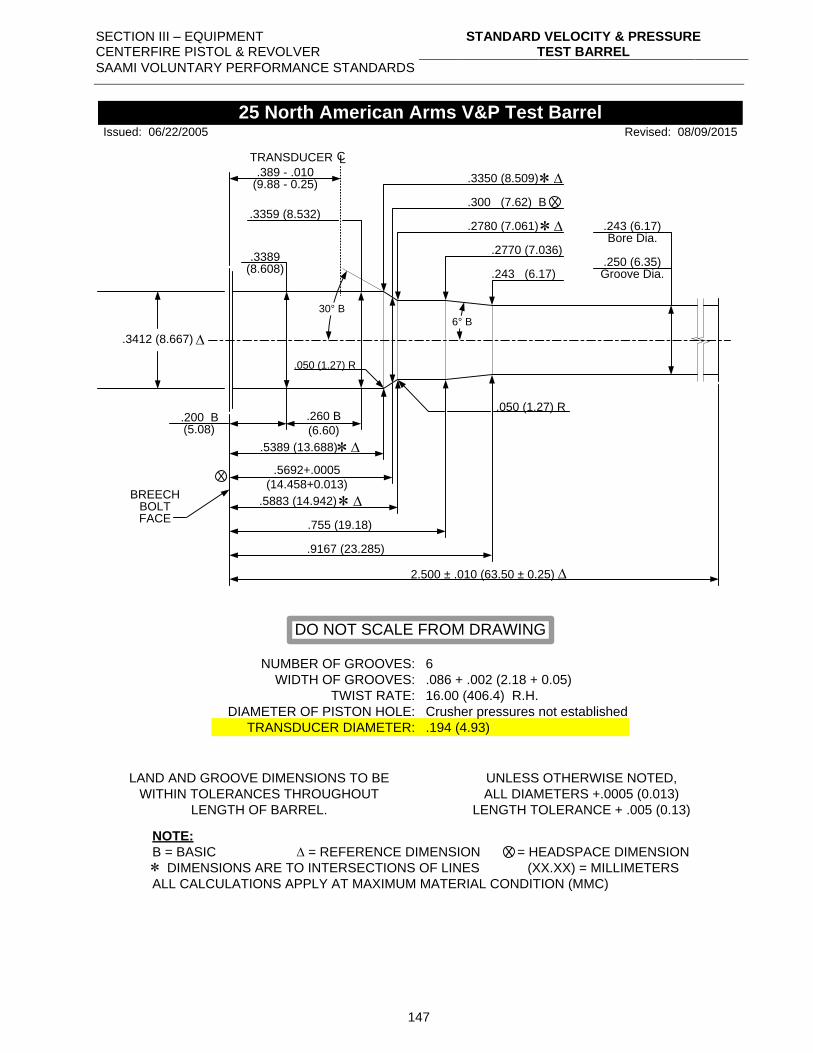
SECTION III – EQUIPMENT CENTERFIRE PISTOL & REVOLVER
STANDARD VELOCITY & PRESSURE TEST BARREL
SAAMI VOLUNTARY PERFORMANCE STANDARDS
147
.3359 (8.532)
.260 B
(6.60).200 B(5.08)
.5389 (13.688)
.5692+.0005
(14.458+0.013)X
.243 (6.17)
.250 (6.35)
Bore Dia.
Groove Dia.
.3412 (8.667)
NUMBER OF GROOVES:
WIDTH OF GROOVES:
TWIST RATE:
DIAMETER OF PISTON HOLE:
TRANSDUCER DIAMETER:
6
.086 + .002 (2.18 + 0.05)
16.00 (406.4) R.H.
Crusher pressures not established
.194 (4.93)
LAND AND GROOVE DIMENSIONS TO BE
WITHIN TOLERANCES THROUGHOUT
LENGTH OF BARREL.
UNLESS OTHERWISE NOTED,
ALL DIAMETERS +.0005 (0.013)
LENGTH TOLERANCE + .005 (0.13)
NOTE:
B = BASIC = REFERENCE DIMENSION = HEADSPACE DIMENSION
DIMENSIONS ARE TO INTERSECTIONS OF LINES (XX.XX) = MILLIMETERS
ALL CALCULATIONS APPLY AT MAXIMUM MATERIAL CONDITION (MMC)
X
25 North American Arms V&P Test Barrel
BREECHBOLTFACE
Revised: 08/09/2015
.300 (7.62) B
.3350 (8.509)
.5883 (14.942)
.3389(8.608)
.2770 (7.036)
.243 (6.17)
.755 (19.18)
.9167 (23.285)
.050 (1.27) R
.050 (1.27) R
30° B
Issued: 06/22/2005
.2780 (7.061)
DO NOT SCALE FROM DRAWING
.389 - .010
TRANSDUCER CL
(9.88 - 0.25)
6° B
X
2.500 ± .010 (63.50 ± 0.25)
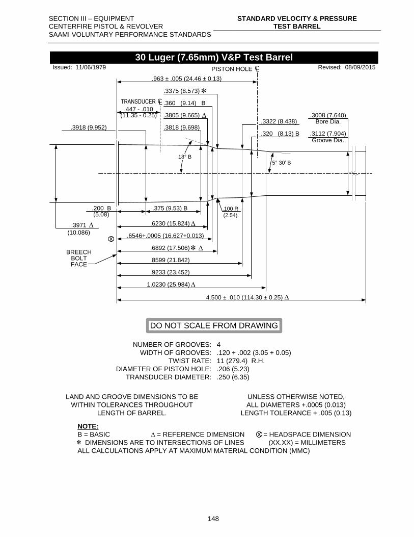
SECTION III – EQUIPMENT CENTERFIRE PISTOL & REVOLVER
STANDARD VELOCITY & PRESSURE TEST BARREL
SAAMI VOLUNTARY PERFORMANCE STANDARDS
148
.3818 (9.698)
.375 (9.53) B.200 B(5.08)
.6230 (15.824)
.6546+.0005 (16.627+0.013)X
.3008 (7.640)
.3112 (7.904)
Bore Dia.
Groove Dia.
.3971
(10.086)
NUMBER OF GROOVES:
WIDTH OF GROOVES:
TWIST RATE:
DIAMETER OF PISTON HOLE:
TRANSDUCER DIAMETER:
4
.120 + .002 (3.05 + 0.05)
11 (279.4) R.H.
.206 (5.23)
.250 (6.35)
LAND AND GROOVE DIMENSIONS TO BE
WITHIN TOLERANCES THROUGHOUT
LENGTH OF BARREL.
UNLESS OTHERWISE NOTED,
ALL DIAMETERS +.0005 (0.013)
LENGTH TOLERANCE + .005 (0.13)
NOTE:
B = BASIC = REFERENCE DIMENSION = HEADSPACE DIMENSION
DIMENSIONS ARE TO INTERSECTIONS OF LINES (XX.XX) = MILLIMETERS
ALL CALCULATIONS APPLY AT MAXIMUM MATERIAL CONDITION (MMC)
X
30 Luger (7.65mm) V&P Test Barrel
BREECHBOLTFACE
Revised: 08/09/2015
.360 (9.14) B
.3805 (9.665)
.8599 (21.842)
.3918 (9.952)
PISTON HOLE CL
.963 ± .005 (24.46 ± 0.13)
.320 (8.13) B
.3322 (8.438)
.6892 (17.506)
.9233 (23.452)
1.0230 (25.984)
.100 R
(2.54)
18° B5° 30’ B
Issued: 11/06/1979
.3375 (8.573)
DO NOT SCALE FROM DRAWING
.447 - .010
TRANSDUCER CL
(11.35 - 0.25)
4.500 ± .010 (114.30 ± 0.25)
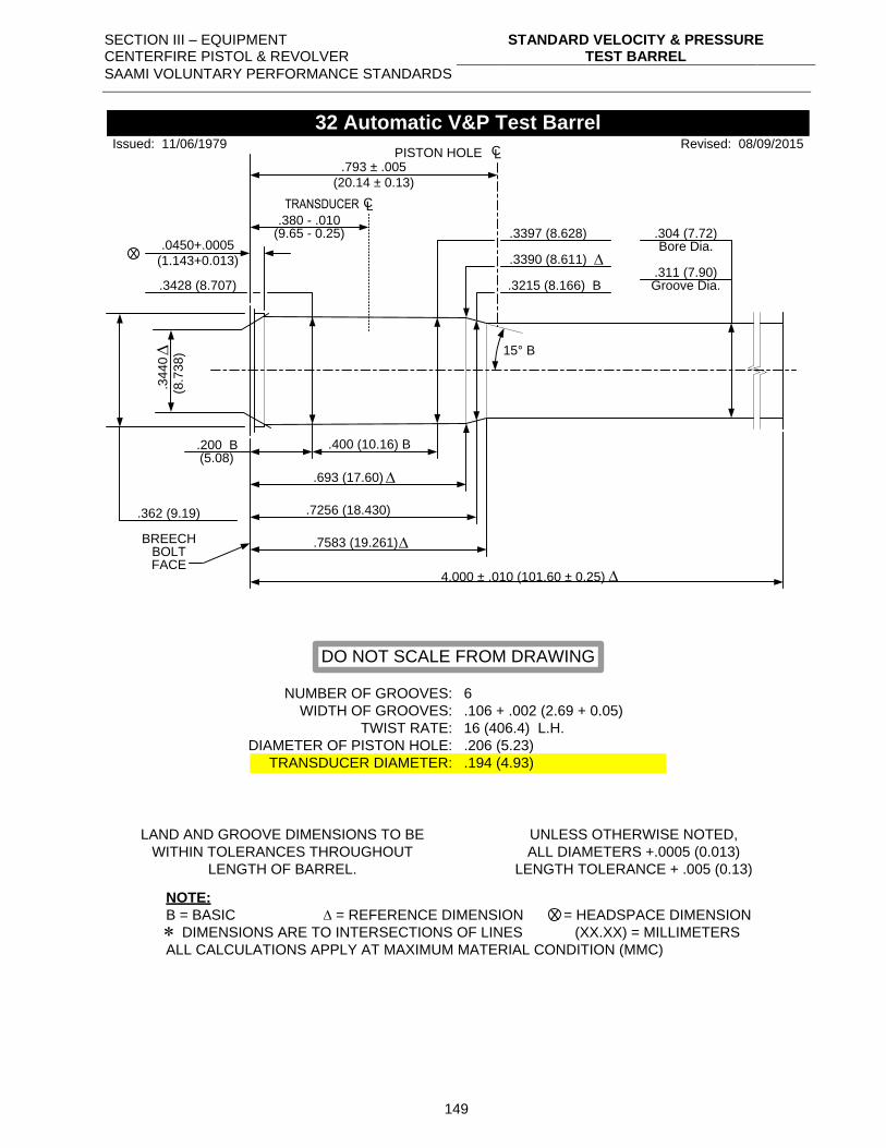
SECTION III – EQUIPMENT CENTERFIRE PISTOL & REVOLVER
STANDARD VELOCITY & PRESSURE TEST BARREL
SAAMI VOLUNTARY PERFORMANCE STANDARDS
149
.793 ± .005
(20.14 ± 0.13)
PISTON HOLE CL
.3390 (8.611)
.3215 (8.166) B
15° B
.400 (10.16) B.200 B(5.08)
.693 (17.60)
.7256 (18.430)
.7583 (19.261)
X
.304 (7.72)
.311 (7.90)
Bore Dia.
Groove Dia.
.362 (9.19)
NUMBER OF GROOVES:
WIDTH OF GROOVES:
TWIST RATE:
DIAMETER OF PISTON HOLE:
TRANSDUCER DIAMETER:
6
.106 + .002 (2.69 + 0.05)
16 (406.4) L.H.
.206 (5.23)
.194 (4.93)
LAND AND GROOVE DIMENSIONS TO BE
WITHIN TOLERANCES THROUGHOUT
LENGTH OF BARREL.
UNLESS OTHERWISE NOTED,
ALL DIAMETERS +.0005 (0.013)
LENGTH TOLERANCE + .005 (0.13)
NOTE:
B = BASIC = REFERENCE DIMENSION = HEADSPACE DIMENSION
DIMENSIONS ARE TO INTERSECTIONS OF LINES (XX.XX) = MILLIMETERS
ALL CALCULATIONS APPLY AT MAXIMUM MATERIAL CONDITION (MMC)
X
32 Automatic V&P Test Barrel
BREECHBOLTFACE
Revised: 08/09/2015Issued: 11/06/1979
.3
44
0
(8.7
38)
.3397 (8.628).0450+.0005
(1.143+0.013)
DO NOT SCALE FROM DRAWING
.3428 (8.707)
.380 - .010
TRANSDUCER CL
(9.65 - 0.25)
4.000 ± .010 (101.60 ± 0.25)
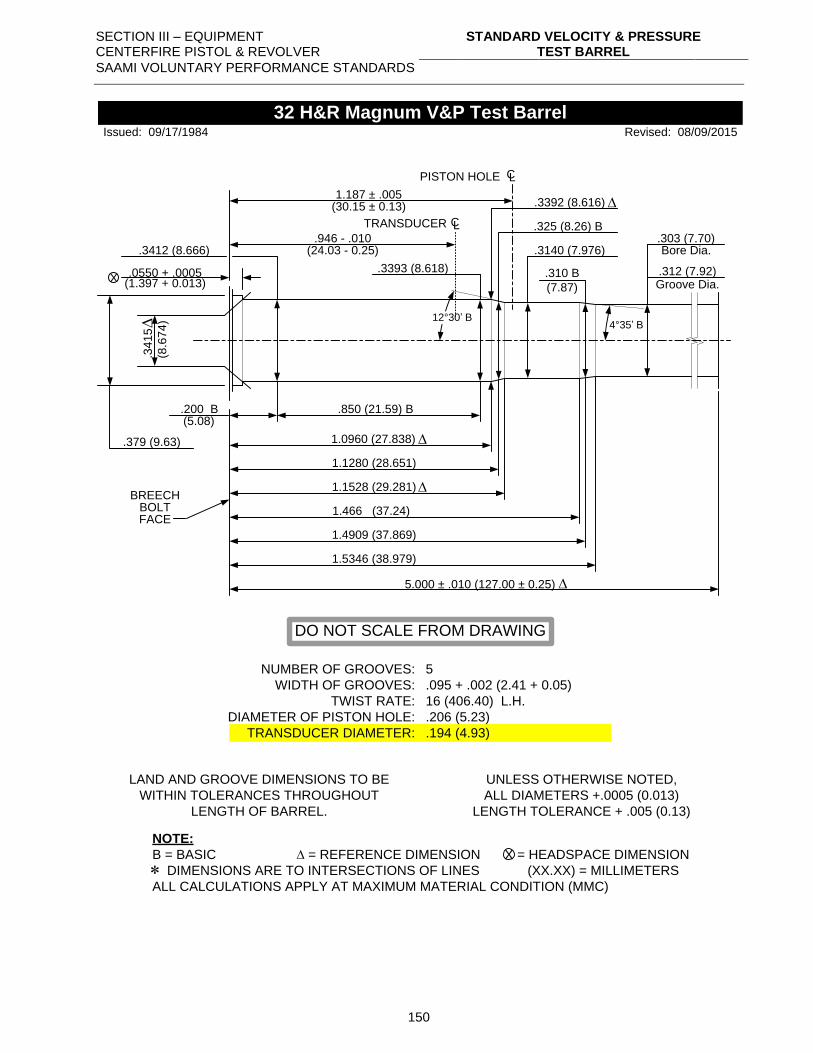
SECTION III – EQUIPMENT CENTERFIRE PISTOL & REVOLVER
STANDARD VELOCITY & PRESSURE TEST BARREL
SAAMI VOLUNTARY PERFORMANCE STANDARDS
150
.0550 + .0005
.850 (21.59) B.200 B(5.08)
1.0960 (27.838)
1.1280 (28.651)
X
.303 (7.70)
.312 (7.92)
Bore Dia.
Groove Dia.
.379 (9.63)
NUMBER OF GROOVES:
WIDTH OF GROOVES:
TWIST RATE:
DIAMETER OF PISTON HOLE:
TRANSDUCER DIAMETER:
5
.095 + .002 (2.41 + 0.05)
16 (406.40) L.H.
.206 (5.23)
.194 (4.93)
LAND AND GROOVE DIMENSIONS TO BE
WITHIN TOLERANCES THROUGHOUT
LENGTH OF BARREL.
UNLESS OTHERWISE NOTED,
ALL DIAMETERS +.0005 (0.013)
LENGTH TOLERANCE + .005 (0.13)
NOTE:
B = BASIC = REFERENCE DIMENSION = HEADSPACE DIMENSION
DIMENSIONS ARE TO INTERSECTIONS OF LINES (XX.XX) = MILLIMETERS
ALL CALCULATIONS APPLY AT MAXIMUM MATERIAL CONDITION (MMC)
X
32 H&R Magnum V&P Test Barrel
BREECHBOLTFACE
Revised: 08/09/2015
.325 (8.26) B
1.466 (37.24)
.3412 (8.666)
PISTON HOLE CL
1.187 ± .005
.3140 (7.976)
1.1528 (29.281)
1.4909 (37.869)
1.5346 (38.979)
12°30’ B4°35’ B
.34
15
(8.6
74
)
(30.15 ± 0.13)
(1.397 + 0.013)
Issued: 09/17/1984
.310 B
(7.87)
DO NOT SCALE FROM DRAWING
.3393 (8.618)
.3392 (8.616)
.946 - .010
TRANSDUCER CL
(24.03 - 0.25)
5.000 ± .010 (127.00 ± 0.25)
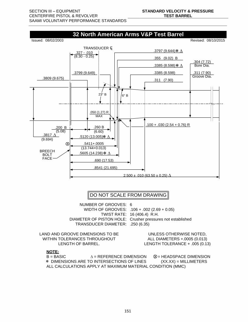
SECTION III – EQUIPMENT CENTERFIRE PISTOL & REVOLVER
STANDARD VELOCITY & PRESSURE TEST BARREL
SAAMI VOLUNTARY PERFORMANCE STANDARDS
151
.3799 (9.649)
.260 B
(6.60).200 B(5.08)
.5120 (13.005)
.5411+.0005
(13.744+0.013)X
.304 (7.72)
.311 (7.90)
Bore Dia.
Groove Dia.
.3817
(9.694)
NUMBER OF GROOVES:
WIDTH OF GROOVES:
TWIST RATE:
DIAMETER OF PISTON HOLE:
TRANSDUCER DIAMETER:
6
.106 + .002 (2.69 + 0.05)
16 (406.4) R.H.
Crusher pressures not established
.250 (6.35)
LAND AND GROOVE DIMENSIONS TO BE
WITHIN TOLERANCES THROUGHOUT
LENGTH OF BARREL.
UNLESS OTHERWISE NOTED,
ALL DIAMETERS +.0005 (0.013)
LENGTH TOLERANCE + .005 (0.13)
NOTE:
B = BASIC = REFERENCE DIMENSION = HEADSPACE DIMENSION
DIMENSIONS ARE TO INTERSECTIONS OF LINES (XX.XX) = MILLIMETERS
ALL CALCULATIONS APPLY AT MAXIMUM MATERIAL CONDITION (MMC)
X
32 North American Arms V&P Test Barrel
BREECHBOLTFACE
Revised: 08/10/2015
.355 (9.02) B
.3797 (9.644)
.5605 (14.238)
.3809 (9.675)
.3385 (8.598)
.311 (7.90)
.690 (17.53)
.8541 (21.695)
.100 + .030 (2.54 + 0.76) R
.050 (1.27) R
MAX
23° B 6° B
Issued: 08/02/2003
.3385 (8.598)
DO NOT SCALE FROM DRAWING
.327 - .010
TRANSDUCER CL
(8.30 - 0.25)
2.500 ± .010 (63.50 ± 0.25)
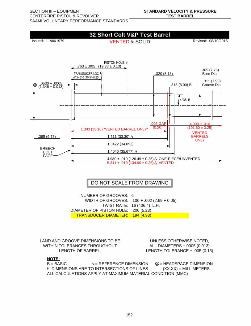
SECTION III – EQUIPMENT CENTERFIRE PISTOL & REVOLVER
STANDARD VELOCITY & PRESSURE TEST BARREL
SAAMI VOLUNTARY PERFORMANCE STANDARDS
152
.0530 + .0005
.320 (8.13)
1.303 (33.10) *VENTED BARREL ONLY*
1.3422 (34.092)
X
.305 (7.75)
.311 (7.90)
Bore Dia.
Groove Dia.
.385 (9.78)
NUMBER OF GROOVES:
WIDTH OF GROOVES:
TWIST RATE:
DIAMETER OF PISTON HOLE:
TRANSDUCER DIAMETER:
6
.106 + .002 (2.69 + 0.05)
16 (406.4) L.H.
.206 (5.23)
.194 (4.93)
LAND AND GROOVE DIMENSIONS TO BE
WITHIN TOLERANCES THROUGHOUT
LENGTH OF BARREL.
UNLESS OTHERWISE NOTED,
ALL DIAMETERS +.0005 (0.013)
LENGTH TOLERANCE + .005 (0.13)
NOTE:
B = BASIC = REFERENCE DIMENSION = HEADSPACE DIMENSION
DIMENSIONS ARE TO INTERSECTIONS OF LINES (XX.XX) = MILLIMETERS
ALL CALCULATIONS APPLY AT MAXIMUM MATERIAL CONDITION (MMC)
X
32 Short Colt V&P Test Barrel
BREECHBOLTFACE
Revised: 08/10/2015
5.311 ± .010 (134.90 ± 0.25) VENTED
PISTON HOLE CL.763 ± .005 (19.38 ± 0.13)
1.4046 (35.677)
.008 GAP 4.000 ± .010(101.60 ± 0.25)
4°35’ B
(0.20)
(1.346 + 0.013)
Issued: 11/06/1979
.315 (8.00) B
DO NOT SCALE FROM DRAWING
.415-.010 (10.54-0.25)TRANSDUCER LOC.CL
4.980 ± .010 (126.49 ± 0.25) ONE-PIECE/UNVENTED
1.311 (33.30)
VENTED & SOLID
VENTEDBARRELS
ONLY
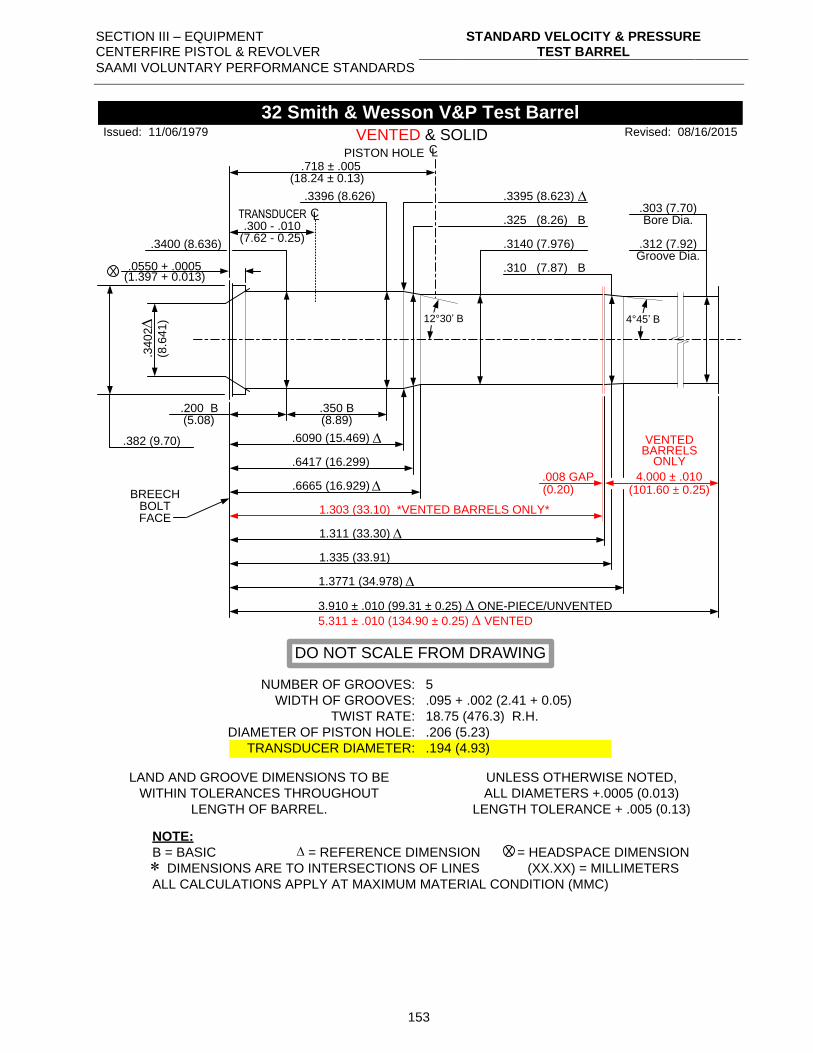
SECTION III – EQUIPMENT CENTERFIRE PISTOL & REVOLVER
STANDARD VELOCITY & PRESSURE TEST BARREL
SAAMI VOLUNTARY PERFORMANCE STANDARDS
153
.0550 + .0005
.3396 (8.626)
.350 B.200 B(5.08)
.6090 (15.469)
.6417 (16.299)
X
.303 (7.70)
.312 (7.92)
Bore Dia.
Groove Dia.
.382 (9.70)
NUMBER OF GROOVES:
WIDTH OF GROOVES:
TWIST RATE:
DIAMETER OF PISTON HOLE:
TRANSDUCER DIAMETER:
5
.095 + .002 (2.41 + 0.05)
18.75 (476.3) R.H.
.206 (5.23)
.194 (4.93)
LAND AND GROOVE DIMENSIONS TO BE
WITHIN TOLERANCES THROUGHOUT
LENGTH OF BARREL.
UNLESS OTHERWISE NOTED,
ALL DIAMETERS +.0005 (0.013)
LENGTH TOLERANCE + .005 (0.13)
NOTE:
B = BASIC = REFERENCE DIMENSION = HEADSPACE DIMENSION
DIMENSIONS ARE TO INTERSECTIONS OF LINES (XX.XX) = MILLIMETERS
ALL CALCULATIONS APPLY AT MAXIMUM MATERIAL CONDITION (MMC)
X
32 Smith & Wesson V&P Test Barrel
BREECHBOLTFACE
.3140 (7.976)
.325 (8.26) B
.3400 (8.636)
1.303 (33.10) *VENTED BARRELS ONLY*
PISTON HOLE CL.718 ± .005
.310 (7.87) B
.6665 (16.929)
1.335 (33.91)
1.3771 (34.978)
5.311 ± .010 (134.90 ± 0.25) VENTED
.008 GAP
12°30’ B
VENTED & SOLID.3
40
2
(8.6
41
)
(18.24 ± 0.13)
(8.89)
(0.20)
(1.397 + 0.013)
Issued: 11/06/1979 Revised: 08/16/2015
DO NOT SCALE FROM DRAWING
.3395 (8.623)
4°45’ B
.300 - .010TRANSDUCER CL
(7.62 - 0.25)
1.311 (33.30)
4.000 ± .010(101.60 ± 0.25)
VENTEDBARRELS
ONLY
3.910 ± .010 (99.31 ± 0.25) ONE-PIECE/UNVENTED
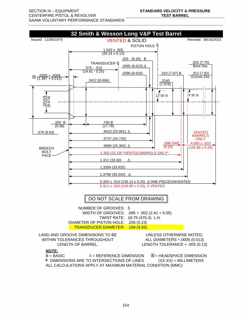
SECTION III – EQUIPMENT CENTERFIRE PISTOL & REVOLVER
STANDARD VELOCITY & PRESSURE TEST BARREL
SAAMI VOLUNTARY PERFORMANCE STANDARDS
154
.0550 + .0005.3396 (8.626)
.700 B.200 B(5.08)
.9410 (23.901)
.9737 (24.732)
X
.303 (7.70)
.312 (7.92)
Bore Dia.
Groove Dia.
.379 (9.63)
NUMBER OF GROOVES:
WIDTH OF GROOVES:
TWIST RATE:
DIAMETER OF PISTON HOLE:
TRANSDUCER DIAMETER:
5
.095 + .002 (2.41 + 0.05)
18.75 (476.3) L.H.
.206 (5.23)
.194 (4.93)
LAND AND GROOVE DIMENSIONS TO BE
WITHIN TOLERANCES THROUGHOUT
LENGTH OF BARREL.
UNLESS OTHERWISE NOTED,
ALL DIAMETERS +.0005 (0.013)
LENGTH TOLERANCE + .005 (0.13)
NOTE:
B = BASIC = REFERENCE DIMENSION = HEADSPACE DIMENSION
DIMENSIONS ARE TO INTERSECTIONS OF LINES (XX.XX) = MILLIMETERS
ALL CALCULATIONS APPLY AT MAXIMUM MATERIAL CONDITION (MMC)
X
32 Smith & Wesson Long V&P Test Barrel
BREECHBOLTFACE
.3140(7.976)
.325 (8.26) B
.3412 (8.666)
1.303 (33.10) *VENTED BARRELS ONLY*
PISTON HOLE CL
1.033 ± .005
.310 (7.87) B
.9985 (25.362)
1.3359 (33.932)
1.3796 (35.042)
5.320 ± .010 (135.13 ± 0.25) ONE-PIECE/UNVENTED
5.311 ± .010 (134.90 ± 0.25) VENTED
.008 GAP 4.000 ± .010
(101.60 ± 0.25)
12°30’ B
VENTED & SOLID.3
41
5
(8.6
74
)
(26.24 ± 0.13)
(17.78)
(0.20)
(1.397 + 0.013)
Issued: 11/06/1979 Revised: 08/16/2015
DO NOT SCALE FROM DRAWING
.3395 (8.623)
4°35’ B
.575 - .010
TRANSDUCER CL
(14.61 - 0.25)
VENTEDBARRELS
ONLY
1.311 (33.30)
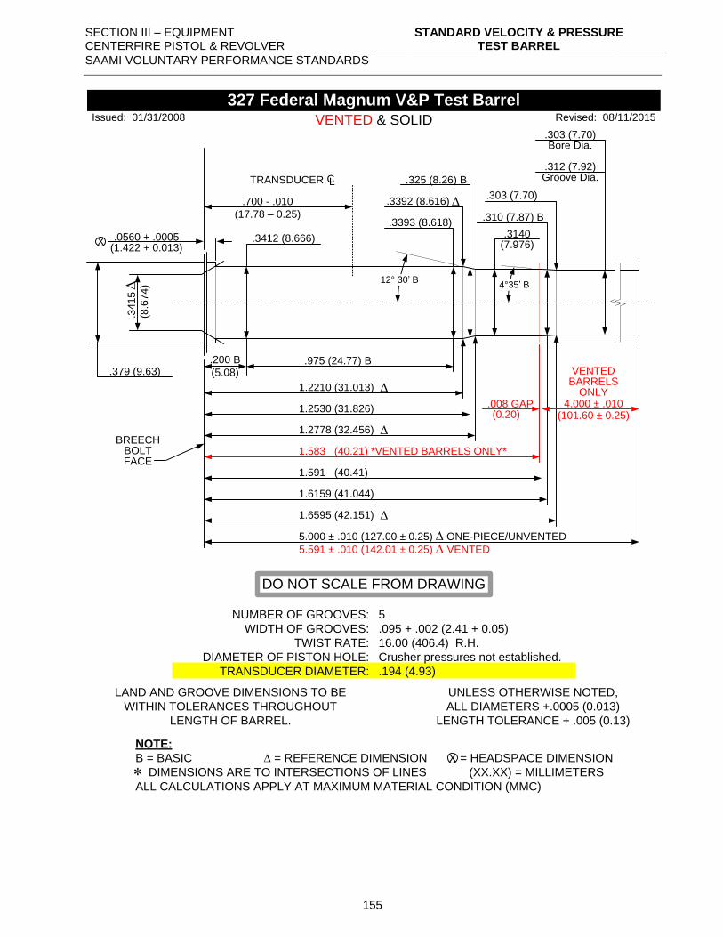
SECTION III – EQUIPMENT CENTERFIRE PISTOL & REVOLVER
STANDARD VELOCITY & PRESSURE TEST BARREL
SAAMI VOLUNTARY PERFORMANCE STANDARDS
155
.0560 + .0005
.3393 (8.618)
.975 (24.77) B.200 B
(5.08)
1.2210 (31.013)
1.2530 (31.826)
X
.303 (7.70)
.312 (7.92)
Bore Dia.
Groove Dia.
.379 (9.63)
NUMBER OF GROOVES:
WIDTH OF GROOVES:
TWIST RATE:
DIAMETER OF PISTON HOLE:
TRANSDUCER DIAMETER:
5
.095 + .002 (2.41 + 0.05)
16.00 (406.4) R.H.
Crusher pressures not established.
.194 (4.93)
LAND AND GROOVE DIMENSIONS TO BE
WITHIN TOLERANCES THROUGHOUT
LENGTH OF BARREL.
UNLESS OTHERWISE NOTED,
ALL DIAMETERS +.0005 (0.013)
LENGTH TOLERANCE + .005 (0.13)
NOTE:
B = BASIC = REFERENCE DIMENSION = HEADSPACE DIMENSION
DIMENSIONS ARE TO INTERSECTIONS OF LINES (XX.XX) = MILLIMETERS
ALL CALCULATIONS APPLY AT MAXIMUM MATERIAL CONDITION (MMC)
X
327 Federal Magnum V&P Test Barrel
BREECHBOLTFACE
.3140(7.976)
.325 (8.26) B
.3412 (8.666)
1.591 (40.41)
.310 (7.87) B
1.2778 (32.456)
1.6159 (41.044)
1.6595 (42.151)
12° 30’ B
.34
15
(8.6
74
)
(1.422 + 0.013)
Issued: 01/31/2008 Revised: 08/11/2015
DO NOT SCALE FROM DRAWING
.3392 (8.616)
4°35’ B
.700 - .010
(17.78 – 0.25)
TRANSDUCER CL
.303 (7.70)
VENTED & SOLID
1.583 (40.21) *VENTED BARRELS ONLY*
.008 GAP(0.20)
VENTEDBARRELS
ONLY4.000 ± .010
(101.60 ± 0.25)
5.000 ± .010 (127.00 ± 0.25) ONE-PIECE/UNVENTED
5.591 ± .010 (142.01 ± 0.25) VENTED
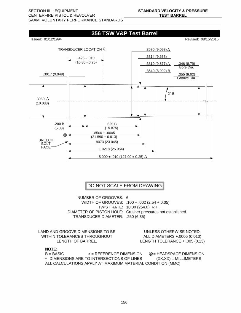
SECTION III – EQUIPMENT CENTERFIRE PISTOL & REVOLVER
STANDARD VELOCITY & PRESSURE TEST BARREL
SAAMI VOLUNTARY PERFORMANCE STANDARDS
156
.3917 (9.949)
.3814 (9.688)
2° B
.625 B(15.875)
.200 B
(5.08)
.8500 + .0005(21.590 + 0.013)
.9073 (23.045)
X
.346 (8.79)
.355 (9.02)
Bore Dia.
Groove Dia.
.3950
(10.033)
NUMBER OF GROOVES:
WIDTH OF GROOVES:
TWIST RATE:
DIAMETER OF PISTON HOLE:
TRANSDUCER DIAMETER:
6
.100 + .002 (2.54 + 0.05)
10.00 (254.0) R.H.
Crusher pressures not established.
.250 (6.35)
LAND AND GROOVE DIMENSIONS TO BE
WITHIN TOLERANCES THROUGHOUT
LENGTH OF BARREL.
UNLESS OTHERWISE NOTED,
ALL DIAMETERS +.0005 (0.013)
LENGTH TOLERANCE + .005 (0.13)
NOTE:
B = BASIC = REFERENCE DIMENSION = HEADSPACE DIMENSION
DIMENSIONS ARE TO INTERSECTIONS OF LINES (XX.XX) = MILLIMETERS
ALL CALCULATIONS APPLY AT MAXIMUM MATERIAL CONDITION (MMC)
X
356 TSW V&P Test Barrel
BREECHBOLTFACE
Revised: 08/15/2015
.3580 (9.093)
.3810 (9.677)
Issued: 01/12/1994
DO NOT SCALE FROM DRAWING
.425 - .010
(10.80 - 0.25)
TRANSDUCER LOCATION CL
.3540 (8.992) B
1.0218 (25.954)
5.000 ± .010 (127.00 ± 0.25)
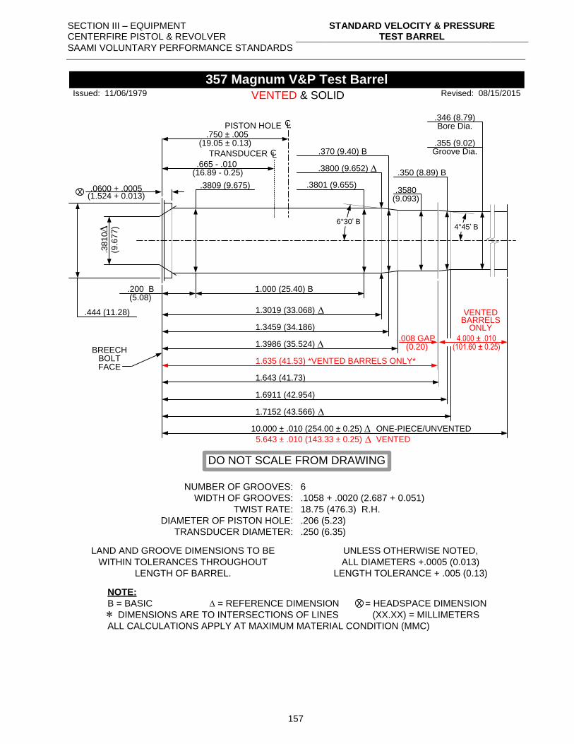
SECTION III – EQUIPMENT CENTERFIRE PISTOL & REVOLVER
STANDARD VELOCITY & PRESSURE TEST BARREL
SAAMI VOLUNTARY PERFORMANCE STANDARDS
157
.0600 + .0005 .3801 (9.655)
1.000 (25.40) B.200 B(5.08)
1.3019 (33.068)
1.3459 (34.186)
X
.346 (8.79)
.355 (9.02)
Bore Dia.
Groove Dia.
.444 (11.28)
NUMBER OF GROOVES:
WIDTH OF GROOVES:
TWIST RATE:
DIAMETER OF PISTON HOLE:
TRANSDUCER DIAMETER:
6
.1058 + .0020 (2.687 + 0.051)
18.75 (476.3) R.H.
.206 (5.23)
.250 (6.35)
LAND AND GROOVE DIMENSIONS TO BE
WITHIN TOLERANCES THROUGHOUT
LENGTH OF BARREL.
UNLESS OTHERWISE NOTED,
ALL DIAMETERS +.0005 (0.013)
LENGTH TOLERANCE + .005 (0.13)
NOTE:
B = BASIC = REFERENCE DIMENSION = HEADSPACE DIMENSION
DIMENSIONS ARE TO INTERSECTIONS OF LINES (XX.XX) = MILLIMETERS
ALL CALCULATIONS APPLY AT MAXIMUM MATERIAL CONDITION (MMC)
X
357 Magnum V&P Test Barrel
BREECHBOLTFACE
.3580(9.093)
.370 (9.40) B
.3809 (9.675)
1.635 (41.53) *VENTED BARRELS ONLY*
PISTON HOLE CL
.750 ± .005
.350 (8.89) B
1.3986 (35.524)
1.6911 (42.954)
1.7152 (43.566)
5.643 ± .010 (143.33 ± 0.25) VENTED
.008 GAP(0.20)
4.000 ± .010(101.60 ± 0.25)
6°30’ B
VENTED & SOLID.3
81
0
(9.6
77
)
(19.05 ± 0.13)
(1.524 + 0.013)
Issued: 11/06/1979 Revised: 08/15/2015
DO NOT SCALE FROM DRAWING
.3800 (9.652)
4°45’ B
.665 - .010(16.89 - 0.25)
TRANSDUCER CL
10.000 ± .010 (254.00 ± 0.25) ONE-PIECE/UNVENTED
VENTEDBARRELS
ONLY
1.643 (41.73)
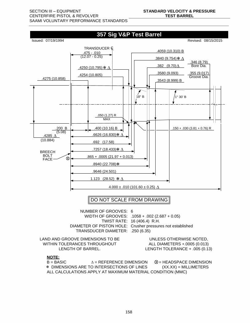
SECTION III – EQUIPMENT CENTERFIRE PISTOL & REVOLVER
STANDARD VELOCITY & PRESSURE TEST BARREL
SAAMI VOLUNTARY PERFORMANCE STANDARDS
158
.4254 (10.805)
.400 (10.16) B.200 B(5.08)
.6626 (16.830)
.692 (17.58)
X
.346 (8.79)
.355 (9.017)
Bore Dia.
Groove Dia.
.4285
(10.884)
NUMBER OF GROOVES:
WIDTH OF GROOVES:
TWIST RATE:
DIAMETER OF PISTON HOLE:
TRANSDUCER DIAMETER:
6
.1058 + .002 (2.687 + 0.05)
16 (406.4) R.H.
Crusher pressures not established
.250 (6.35)
LAND AND GROOVE DIMENSIONS TO BE
WITHIN TOLERANCES THROUGHOUT
LENGTH OF BARREL.
UNLESS OTHERWISE NOTED,
ALL DIAMETERS +.0005 (0.013)
LENGTH TOLERANCE + .005 (0.13)
NOTE:
B = BASIC = REFERENCE DIMENSION = HEADSPACE DIMENSION
DIMENSIONS ARE TO INTERSECTIONS OF LINES (XX.XX) = MILLIMETERS
ALL CALCULATIONS APPLY AT MAXIMUM MATERIAL CONDITION (MMC)
X
357 Sig V&P Test Barrel
BREECHBOLTFACE
Revised: 08/15/2015
.4059 (10.310) B
.4250 (10.795)
.7257 (18.433)
.4275 (10.858)
.382 (9.70)
.3580 (9.093)
.865 + .0005 (21.97 + 0.013)
.8940 (22.708)
.9646 (24.501)
.150 + .030 (3.81 + 0.76) R
.050 (1.27) R
MAX
18° B 1° 30’ B
Issued: 07/19/1994
.3840 (9.754)
DO NOT SCALE FROM DRAWING
.3543 (8.999) B
1.123 (28.52)
.475 - .010
TRANSDUCER CL
(12.07 - 0.25)
4.000 ± .010 (101.60 ± 0.25)
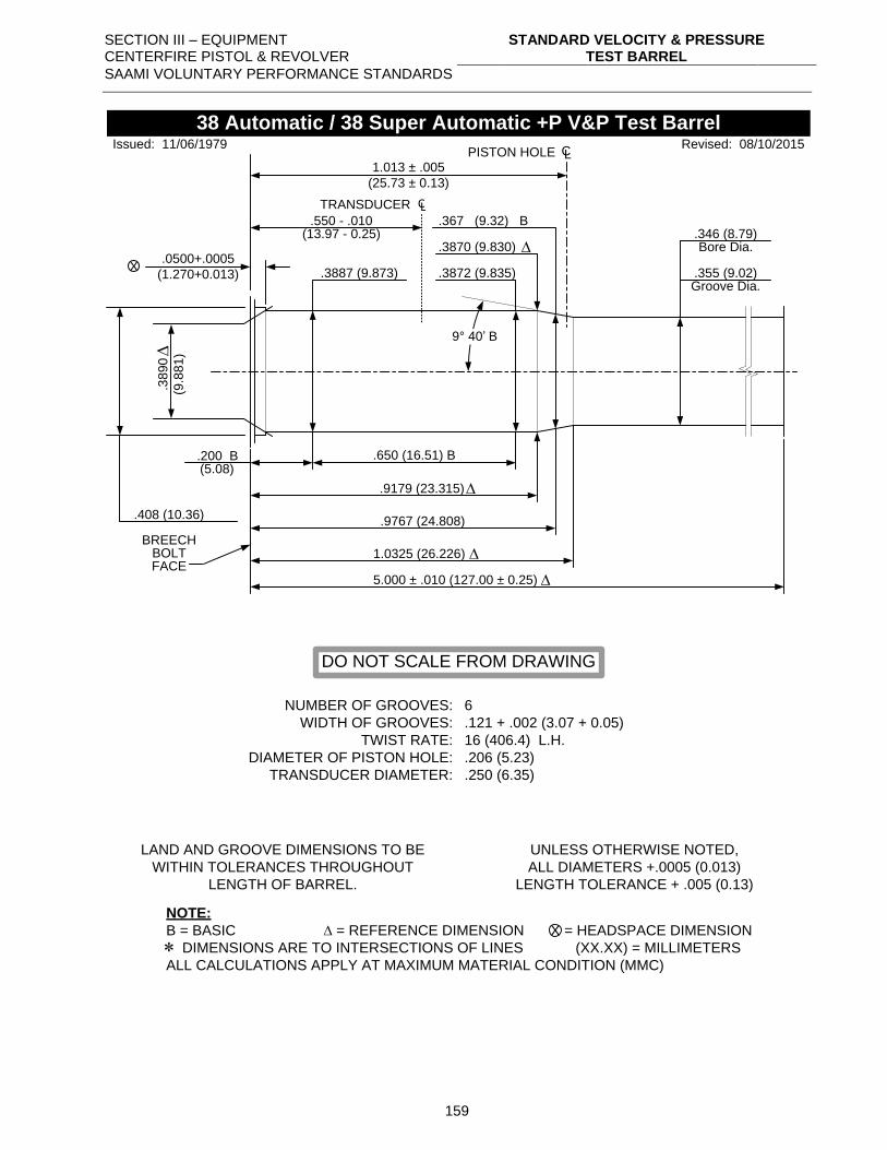
SECTION III – EQUIPMENT CENTERFIRE PISTOL & REVOLVER
STANDARD VELOCITY & PRESSURE TEST BARREL
SAAMI VOLUNTARY PERFORMANCE STANDARDS
159
1.013 ± .005
(25.73 ± 0.13)
PISTON HOLE CL
.3870 (9.830)
.367 (9.32) B
.650 (16.51) B.200 B(5.08)
.9179 (23.315)
.9767 (24.808)
1.0325 (26.226)
X
.346 (8.79)
.355 (9.02)
Bore Dia.
Groove Dia.
.408 (10.36)
NUMBER OF GROOVES:
WIDTH OF GROOVES:
TWIST RATE:
DIAMETER OF PISTON HOLE:
TRANSDUCER DIAMETER:
6
.121 + .002 (3.07 + 0.05)
16 (406.4) L.H.
.206 (5.23)
.250 (6.35)
LAND AND GROOVE DIMENSIONS TO BE
WITHIN TOLERANCES THROUGHOUT
LENGTH OF BARREL.
UNLESS OTHERWISE NOTED,
ALL DIAMETERS +.0005 (0.013)
LENGTH TOLERANCE + .005 (0.13)
NOTE:
B = BASIC = REFERENCE DIMENSION = HEADSPACE DIMENSION
DIMENSIONS ARE TO INTERSECTIONS OF LINES (XX.XX) = MILLIMETERS
ALL CALCULATIONS APPLY AT MAXIMUM MATERIAL CONDITION (MMC)
X
38 Automatic / 38 Super Automatic +P V&P Test Barrel
BREECHBOLTFACE
Revised: 08/10/2015Issued: 11/06/1979
.3
89
0
(9.8
81
)
.3872 (9.835).0500+.0005
(1.270+0.013)
DO NOT SCALE FROM DRAWING
.3887 (9.873)
9° 40’ B
.550 - .010
TRANSDUCER CL
(13.97 - 0.25)
5.000 ± .010 (127.00 ± 0.25)
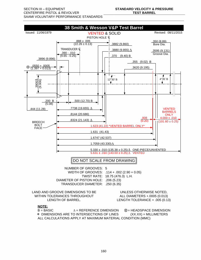
SECTION III – EQUIPMENT CENTERFIRE PISTOL & REVOLVER
STANDARD VELOCITY & PRESSURE TEST BARREL
SAAMI VOLUNTARY PERFORMANCE STANDARDS
160
.0550 + .0005
.3882 (9.860)
.500 (12.70) B.200 B(5.08)
.7738 (19.655)
.8144 (20.686)
X
.350 (8.89)
.3595 (9.131)
Bore Dia.
Groove Dia.
.444 (11.28)
NUMBER OF GROOVES:
WIDTH OF GROOVES:
TWIST RATE:
DIAMETER OF PISTON HOLE:
TRANSDUCER DIAMETER:
5
.114 + .002 (2.90 + 0.05)
18.75 (476.3) L.H.
.206 (5.23)
.250 (6.35)
LAND AND GROOVE DIMENSIONS TO BE
WITHIN TOLERANCES THROUGHOUT
LENGTH OF BARREL.
UNLESS OTHERWISE NOTED,
ALL DIAMETERS +.0005 (0.013)
LENGTH TOLERANCE + .005 (0.13)
NOTE:
B = BASIC = REFERENCE DIMENSION = HEADSPACE DIMENSION
DIMENSIONS ARE TO INTERSECTIONS OF LINES (XX.XX) = MILLIMETERS
ALL CALCULATIONS APPLY AT MAXIMUM MATERIAL CONDITION (MMC)
X
38 Smith & Wesson V&P Test Barrel
BREECHBOLTFACE
.3620 (9.195)
.370 (9.40) B.3896 (9.896)
1.623 (41.22) *VENTED BARREL ONLY*
PISTON HOLE CL
.888 ± .005
.355 (9.02) B
.8324 (21.143)
1.6747 (42.537)
1.7059 (43.330)
5.631 ± .010 (143.03 ± 0.25) VENTED
.008 4.000 ± .010
(101.60 ± 0.25)
12°30’ B
VENTED & SOLID.3
90
0
(9.9
06
)
(22.26 ± 0.13)
(0.20)
(1.397 + 0.013)
Issued: 11/06/1979 Revised: 08/11/2015
DO NOT SCALE FROM DRAWING
.3880 (9.855)
4°35’ B
.390 - .010
TRANSDUCER CL
(9.65 - 0.25)
VENTEDBARRELS
ONLY
5.330 ± .010 (135.38 ± 0.25) ONE-PIECE/UNVENTED
1.631 (41.43)
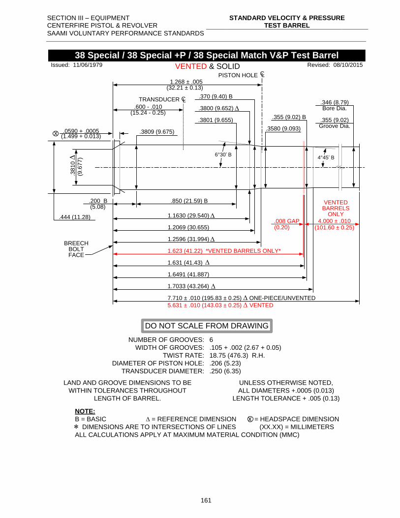
SECTION III – EQUIPMENT CENTERFIRE PISTOL & REVOLVER
STANDARD VELOCITY & PRESSURE TEST BARREL
SAAMI VOLUNTARY PERFORMANCE STANDARDS
161
.0590 + .0005
.3801 (9.655)
.850 (21.59) B.200 B(5.08)
1.1630 (29.540)
1.2069 (30.655)
X
.346 (8.79)
.355 (9.02)
Bore Dia.
Groove Dia.
.444 (11.28)
NUMBER OF GROOVES:
WIDTH OF GROOVES:
TWIST RATE:
DIAMETER OF PISTON HOLE:
TRANSDUCER DIAMETER:
6
.105 + .002 (2.67 + 0.05)
18.75 (476.3) R.H.
.206 (5.23)
.250 (6.35)
LAND AND GROOVE DIMENSIONS TO BE
WITHIN TOLERANCES THROUGHOUT
LENGTH OF BARREL.
UNLESS OTHERWISE NOTED,
ALL DIAMETERS +.0005 (0.013)
LENGTH TOLERANCE + .005 (0.13)
NOTE:
B = BASIC = REFERENCE DIMENSION = HEADSPACE DIMENSION
DIMENSIONS ARE TO INTERSECTIONS OF LINES (XX.XX) = MILLIMETERS
ALL CALCULATIONS APPLY AT MAXIMUM MATERIAL CONDITION (MMC)
X
38 Special / 38 Special +P / 38 Special Match V&P Test Barrel
BREECHBOLTFACE
.3580 (9.093)
.370 (9.40) B
.3809 (9.675)
1.623 (41.22) *VENTED BARRELS ONLY*
PISTON HOLE CL
1.268 ± .005
.355 (9.02) B
1.2596 (31.994)
1.6491 (41.887)
1.7033 (43.264)
7.710 ± .010 (195.83 ± 0.25) ONE-PIECE/UNVENTED
5.631 ± .010 (143.03 ± 0.25) VENTED
6°30’ B
VENTED & SOLID.3
81
0
(9.6
77
)
(32.21 ± 0.13)
(1.499 + 0.013)
Issued: 11/06/1979 Revised: 08/10/2015
DO NOT SCALE FROM DRAWING
.3800 (9.652)
4°45’ B
.600 - .010
TRANSDUCER CL
(15.24 - 0.25)
1.631 (41.43)
.008 GAP(0.20)
VENTEDBARRELS
ONLY4.000 ± .010
(101.60 ± 0.25)
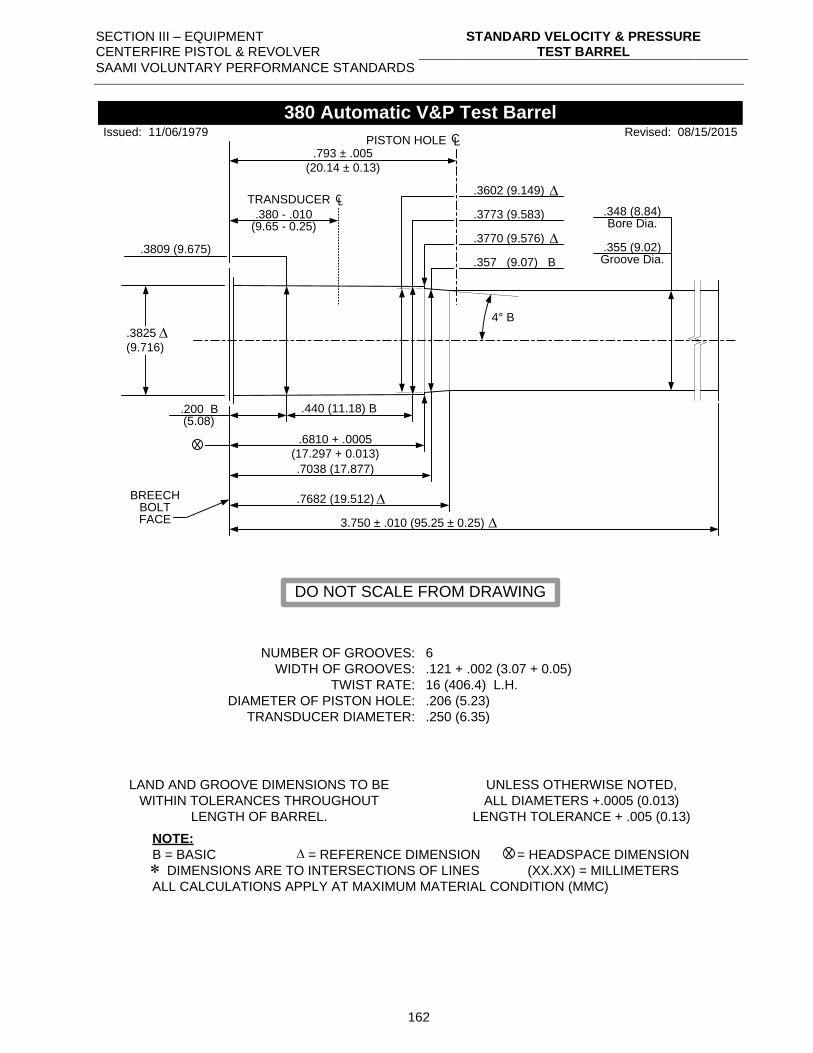
SECTION III – EQUIPMENT CENTERFIRE PISTOL & REVOLVER
STANDARD VELOCITY & PRESSURE TEST BARREL
SAAMI VOLUNTARY PERFORMANCE STANDARDS
162
.3809 (9.675)
.793 ± .005
(20.14 ± 0.13)
PISTON HOLE CL
.3773 (9.583)
.3770 (9.576)
4° B
.440 (11.18) B.200 B(5.08)
.6810 + .0005
(17.297 + 0.013)
.7038 (17.877)
.7682 (19.512)
X
.348 (8.84)
.355 (9.02)
Bore Dia.
Groove Dia.
.3825
(9.716)
NUMBER OF GROOVES:
WIDTH OF GROOVES:
TWIST RATE:
DIAMETER OF PISTON HOLE:
TRANSDUCER DIAMETER:
6
.121 + .002 (3.07 + 0.05)
16 (406.4) L.H.
.206 (5.23)
.250 (6.35)
LAND AND GROOVE DIMENSIONS TO BE
WITHIN TOLERANCES THROUGHOUT
LENGTH OF BARREL.
UNLESS OTHERWISE NOTED,
ALL DIAMETERS +.0005 (0.013)
LENGTH TOLERANCE + .005 (0.13)
NOTE:
B = BASIC = REFERENCE DIMENSION = HEADSPACE DIMENSION
DIMENSIONS ARE TO INTERSECTIONS OF LINES (XX.XX) = MILLIMETERS
ALL CALCULATIONS APPLY AT MAXIMUM MATERIAL CONDITION (MMC)
X
380 Automatic V&P Test Barrel
BREECHBOLTFACE
Revised: 08/15/2015
.357 (9.07) B
Issued: 11/06/1979
.3602 (9.149)
DO NOT SCALE FROM DRAWING
.380 - .010
TRANSDUCER CL
(9.65 - 0.25)
3.750 ± .010 (95.25 ± 0.25)
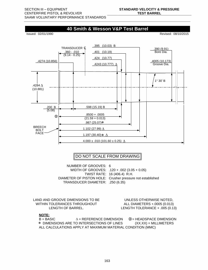
SECTION III – EQUIPMENT CENTERFIRE PISTOL & REVOLVER
STANDARD VELOCITY & PRESSURE TEST BARREL
SAAMI VOLUNTARY PERFORMANCE STANDARDS
163
.424 (10.77)
.401 (10.19)
1° 30’ B
.598 (15.19) B.200 B(5.08)
.8500 + .0005
(21.59 + 0.013)
.987 (25.07)
1.102 (27.99)
X
.390 (9.91)
.4005 (10.173)
Bore Dia.
Groove Dia.
.4284
(10.881)
NUMBER OF GROOVES:
WIDTH OF GROOVES:
TWIST RATE:
DIAMETER OF PISTON HOLE:
TRANSDUCER DIAMETER:
6
.120 + .002 (3.05 + 0.05)
16 (406.4) R.H.
Crusher pressure not established
.250 (6.35)
LAND AND GROOVE DIMENSIONS TO BE
WITHIN TOLERANCES THROUGHOUT
LENGTH OF BARREL.
UNLESS OTHERWISE NOTED,
ALL DIAMETERS +.0005 (0.013)
LENGTH TOLERANCE + .005 (0.13)
NOTE:
B = BASIC = REFERENCE DIMENSION = HEADSPACE DIMENSION
DIMENSIONS ARE TO INTERSECTIONS OF LINES (XX.XX) = MILLIMETERS
ALL CALCULATIONS APPLY AT MAXIMUM MATERIAL CONDITION (MMC)
X
40 Smith & Wesson V&P Test Barrel
BREECHBOLTFACE
Revised: 08/10/2015
.395 (10.03) B
Issued: 02/01/1990
.4243 (10.777)
DO NOT SCALE FROM DRAWING
.4274 (10.856)
1.197 (30.40)
.360 - .010
TRANSDUCER CL
(9.14 - 0.25)
4.000 ± .010 (101.60 ± 0.25)
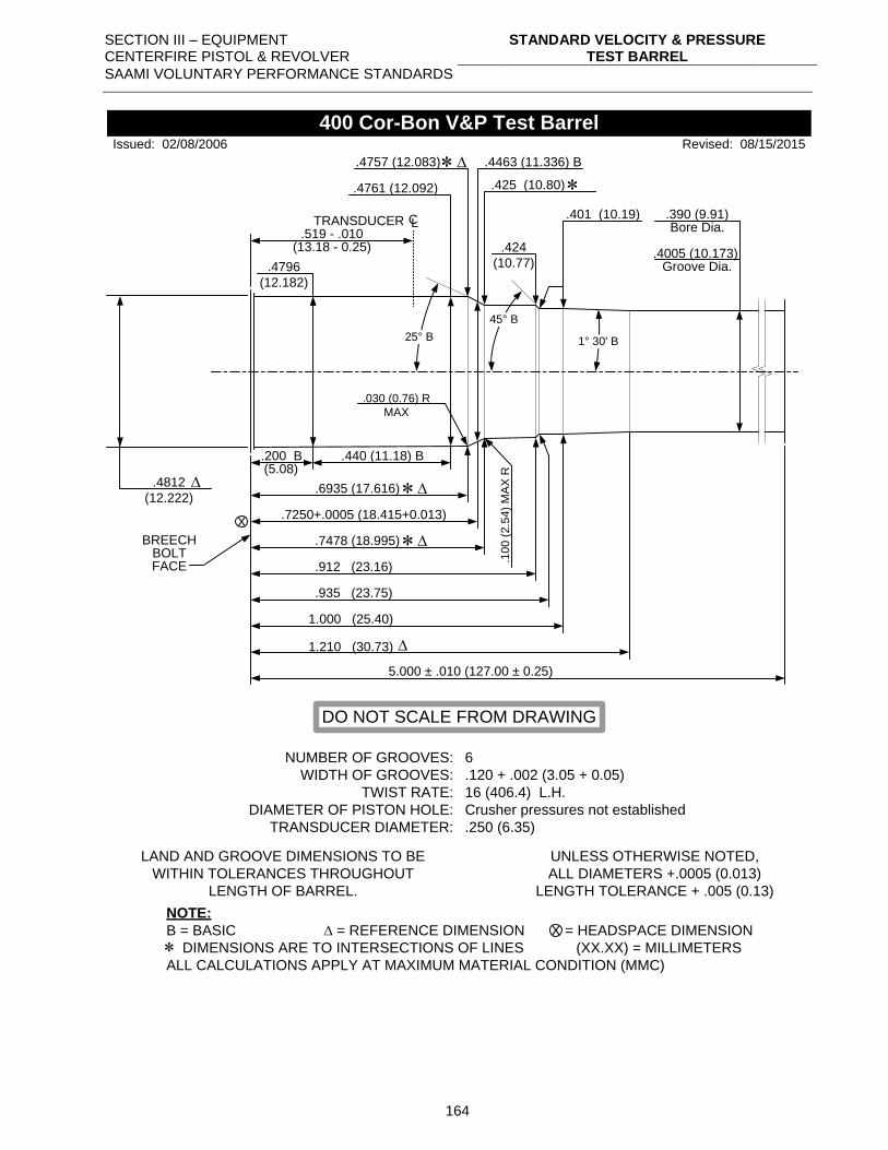
SECTION III – EQUIPMENT CENTERFIRE PISTOL & REVOLVER
STANDARD VELOCITY & PRESSURE TEST BARREL
SAAMI VOLUNTARY PERFORMANCE STANDARDS
164
.4761 (12.092)
.440 (11.18) B.200 B(5.08)
.6935 (17.616)
.7250+.0005 (18.415+0.013)X
.390 (9.91)
.4005 (10.173)
Bore Dia.
Groove Dia.
.4812
(12.222)
NUMBER OF GROOVES:
WIDTH OF GROOVES:
TWIST RATE:
DIAMETER OF PISTON HOLE:
TRANSDUCER DIAMETER:
6
.120 + .002 (3.05 + 0.05)
16 (406.4) L.H.
Crusher pressures not established
.250 (6.35)
LAND AND GROOVE DIMENSIONS TO BE
WITHIN TOLERANCES THROUGHOUT
LENGTH OF BARREL.
UNLESS OTHERWISE NOTED,
ALL DIAMETERS +.0005 (0.013)
LENGTH TOLERANCE + .005 (0.13)
NOTE:
B = BASIC = REFERENCE DIMENSION = HEADSPACE DIMENSION
DIMENSIONS ARE TO INTERSECTIONS OF LINES (XX.XX) = MILLIMETERS
ALL CALCULATIONS APPLY AT MAXIMUM MATERIAL CONDITION (MMC)
X
400 Cor-Bon V&P Test Barrel
BREECHBOLTFACE
Revised: 08/15/2015
.4463 (11.336) B.4757 (12.083)
.7478 (18.995)
.4796
(12.182)
.424
(10.77)
.401 (10.19)
.912 (23.16)
1.000 (25.40)
.10
0 (
2.5
4)
MA
X R
.030 (0.76) R
MAX
25° B
Issued: 02/08/2006
.425 (10.80)
DO NOT SCALE FROM DRAWING
.519 - .010TRANSDUCER CL
(13.18 - 0.25)
1° 30' B
45° B
1.210 (30.73)
.935 (23.75)
5.000 ± .010 (127.00 ± 0.25)
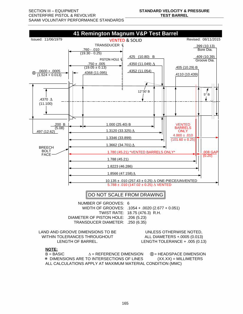
SECTION III – EQUIPMENT CENTERFIRE PISTOL & REVOLVER
STANDARD VELOCITY & PRESSURE TEST BARREL
SAAMI VOLUNTARY PERFORMANCE STANDARDS
165
.0600 + .0005 .4352 (11.054)
1.000 (25.40) B.200 B(5.08)
1.3120 (33.325)
1.3346 (33.899)
X
.399 (10.13)
.409 (10.39)
Bore Dia.
Groove Dia.
.497 (12.62)
NUMBER OF GROOVES:
WIDTH OF GROOVES:
TWIST RATE:
DIAMETER OF PISTON HOLE:
TRANSDUCER DIAMETER:
6
.1054 + .0020 (2.677 + 0.051)
18.75 (476.3) R.H.
.206 (5.23)
.250 (6.35)
LAND AND GROOVE DIMENSIONS TO BE
WITHIN TOLERANCES THROUGHOUT
LENGTH OF BARREL.
UNLESS OTHERWISE NOTED,
ALL DIAMETERS +.0005 (0.013)
LENGTH TOLERANCE + .005 (0.13)
NOTE:
B = BASIC = REFERENCE DIMENSION = HEADSPACE DIMENSION
DIMENSIONS ARE TO INTERSECTIONS OF LINES (XX.XX) = MILLIMETERS
ALL CALCULATIONS APPLY AT MAXIMUM MATERIAL CONDITION (MMC)
X
41 Remington Magnum V&P Test Barrel
BREECHBOLTFACE
.4110 (10.439)
.425 (10.80) B
.4368 (11.095)
1.780 (45.21) *VENTED BARRELS ONLY*
PISTON HOLE CL.750 ± .005
.405 (10.29) B
1.3662 (34.701)
1.8223 (46.286)
1.8566 (47.158)
10.135 ± .010 (257.43 ± 0.25) ONE-PIECE/UNVENTED 5.788 ± .010 (147.02 ± 0.25) VENTED
.008 GAP
4.000 ± .010
(101.60 ± 0.25)
12°30’ B
VENTED & SOLID
(19.05 ± 0.13)
(0.20)
(1.524 + 0.013)
Issued: 11/06/1979 Revised: 08/11/2015
DO NOT SCALE FROM DRAWING
.4350 (11.049)
5° B
.4370
(11.100)
.760 - .010
TRANSDUCER CL
(19.30 - 0.25)
VENTEDBARRELS
ONLY
1.788 (45.21)
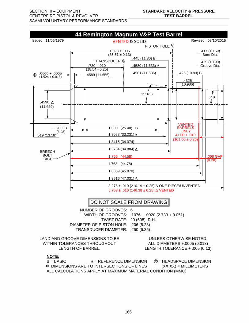
SECTION III – EQUIPMENT CENTERFIRE PISTOL & REVOLVER
STANDARD VELOCITY & PRESSURE TEST BARREL
SAAMI VOLUNTARY PERFORMANCE STANDARDS
166
.0600 + .0005 .4581 (11.636)
1.000 (25.40) B.200 B(5.08)
1.3083 (33.231)
1.3415 (34.074)
X
.417 (10.59)
.429 (10.90)
Bore Dia.
Groove Dia.
.519 (13.18)
NUMBER OF GROOVES:
WIDTH OF GROOVES:
TWIST RATE:
DIAMETER OF PISTON HOLE:
TRANSDUCER DIAMETER:
6
.1076 + .0020 (2.733 + 0.051)
20 (508) R.H.
.206 (5.23)
.250 (6.35)
LAND AND GROOVE DIMENSIONS TO BE
WITHIN TOLERANCES THROUGHOUT
LENGTH OF BARREL.
UNLESS OTHERWISE NOTED,
ALL DIAMETERS +.0005 (0.013)
LENGTH TOLERANCE + .005 (0.13)
NOTE:
B = BASIC = REFERENCE DIMENSION = HEADSPACE DIMENSION
DIMENSIONS ARE TO INTERSECTIONS OF LINES (XX.XX) = MILLIMETERS
ALL CALCULATIONS APPLY AT MAXIMUM MATERIAL CONDITION (MMC)
X
44 Remington Magnum V&P Test Barrel
BREECHBOLTFACE
.4325 (10.986)
.445 (11.30) B
.4589 (11.656)
1.755 (44.58)
PISTON HOLE CL
1.398 ± .005
.425 (10.80) B
1.3734 (34.884)
1.8059 (45.870)
1.8516 (47.031)
8.275 ± .010 (210.19 ± 0.25) ONE-PIECE/UNVENTED
5.763 ± .010 (146.38 ± 0.25) VENTED
.008 GAP
4.000 ± .010
(101.60 ± 0.25)
11° 6’ B
VENTED & SOLID
(35.51 ± 0.13)
(0.20)
(1.524 + 0.013)
Issued: 11/06/1979 Revised: 08/10/2015
DO NOT SCALE FROM DRAWING
.4580 (11.633)
5° B
.4590
(11.659)
.730 - .010
TRANSDUCER CL
(18.54 - 0.25)
1.763 (44.78)
VENTEDBARRELS
ONLY
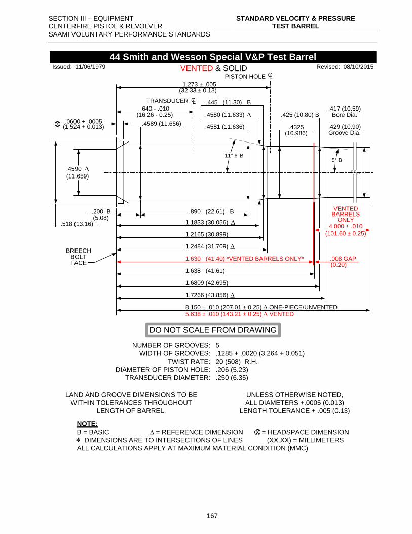
SECTION III – EQUIPMENT CENTERFIRE PISTOL & REVOLVER
STANDARD VELOCITY & PRESSURE TEST BARREL
SAAMI VOLUNTARY PERFORMANCE STANDARDS
167
.0600 + .0005.4581 (11.636)
.890 (22.61) B.200 B(5.08)
1.1833 (30.056)
1.2165 (30.899)
X
.417 (10.59)
.429 (10.90)
Bore Dia.
Groove Dia.
.518 (13.16)
NUMBER OF GROOVES:
WIDTH OF GROOVES:
TWIST RATE:
DIAMETER OF PISTON HOLE:
TRANSDUCER DIAMETER:
5
.1285 + .0020 (3.264 + 0.051)
20 (508) R.H.
.206 (5.23)
.250 (6.35)
LAND AND GROOVE DIMENSIONS TO BE
WITHIN TOLERANCES THROUGHOUT
LENGTH OF BARREL.
UNLESS OTHERWISE NOTED,
ALL DIAMETERS +.0005 (0.013)
LENGTH TOLERANCE + .005 (0.13)
NOTE:
B = BASIC = REFERENCE DIMENSION = HEADSPACE DIMENSION
DIMENSIONS ARE TO INTERSECTIONS OF LINES (XX.XX) = MILLIMETERS
ALL CALCULATIONS APPLY AT MAXIMUM MATERIAL CONDITION (MMC)
X
44 Smith and Wesson Special V&P Test Barrel
BREECHBOLTFACE
.4325 (10.986)
.445 (11.30) B
.4589 (11.656)
1.630 (41.40) *VENTED BARRELS ONLY*
PISTON HOLE CL
1.273 ± .005
.425 (10.80) B
1.2484 (31.709)
1.6809 (42.695)
1.7266 (43.856)
8.150 ± .010 (207.01 ± 0.25) ONE-PIECE/UNVENTED5.638 ± .010 (143.21 ± 0.25) VENTED
.008 GAP
4.000 ± .010
(101.60 ± 0.25)
11° 6’ B
VENTED & SOLID
(32.33 ± 0.13)
(0.20)
(1.524 + 0.013)
Issued: 11/06/1979 Revised: 08/10/2015
DO NOT SCALE FROM DRAWING
.4580 (11.633)
5° B
.4590
(11.659)
.640 - .010
TRANSDUCER CL
(16.26 - 0.25)
1.638 (41.61)
VENTEDBARRELS
ONLY
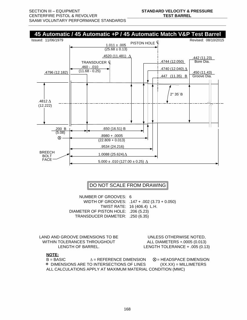
SECTION III – EQUIPMENT CENTERFIRE PISTOL & REVOLVER
STANDARD VELOCITY & PRESSURE TEST BARREL
SAAMI VOLUNTARY PERFORMANCE STANDARDS
168
.4744 (12.050)
.4740 (12.040)
2° 35’ B
.650 (16.51) B.200 B(5.08)
.8980 + .0005
(22.809 + 0.013)
.9534 (24.216)
1.0088 (25.624)
X
.442 (11.23)
.450 (11.43)
Bore Dia.
Groove Dia.
.4812
(12.222)
NUMBER OF GROOVES:
WIDTH OF GROOVES:
TWIST RATE:
DIAMETER OF PISTON HOLE:
TRANSDUCER DIAMETER:
6
.147 + .002 (3.73 + 0.050)
16 (406.4) L.H.
.206 (5.23)
.250 (6.35)
LAND AND GROOVE DIMENSIONS TO BE
WITHIN TOLERANCES THROUGHOUT
LENGTH OF BARREL.
UNLESS OTHERWISE NOTED,
ALL DIAMETERS +.0005 (0.013)
LENGTH TOLERANCE + .005 (0.13)
NOTE:
B = BASIC = REFERENCE DIMENSION = HEADSPACE DIMENSION
DIMENSIONS ARE TO INTERSECTIONS OF LINES (XX.XX) = MILLIMETERS
ALL CALCULATIONS APPLY AT MAXIMUM MATERIAL CONDITION (MMC)
X
45 Automatic / 45 Automatic +P / 45 Automatic Match V&P Test Barrel
BREECHBOLTFACE
Revised: 08/10/2015
.447 (11.35) B
Issued: 11/06/1979
.4520 (11.481)
DO NOT SCALE FROM DRAWING
.4796 (12.182)
PISTON HOLE CL1.011 ± .005
(25.68 ± 0.13)
.460 - .010
TRANSDUCER CL
(11.68 - 0.25)
5.000 ± .010 (127.00 ± 0.25)
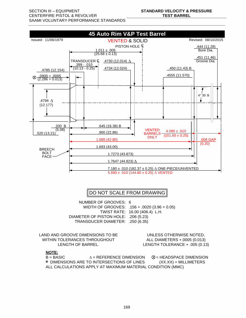
SECTION III – EQUIPMENT CENTERFIRE PISTOL & REVOLVER
STANDARD VELOCITY & PRESSURE TEST BARREL
SAAMI VOLUNTARY PERFORMANCE STANDARDS
169
.0900 + .0005
.4734 (12.024)
.645 (16.38) B.200 B(5.08)
.900 (22.86)
X
.444 (11.28)
.451 (11.46)
Bore Dia.
Groove Dia.
.520 (13.21)
NUMBER OF GROOVES:
WIDTH OF GROOVES:
TWIST RATE:
DIAMETER OF PISTON HOLE:
TRANSDUCER DIAMETER:
6
.156 + .0020 (3.96 + 0.05)
16.00 (406.4) L.H.
.206 (5.23)
.250 (6.35)
LAND AND GROOVE DIMENSIONS TO BE
WITHIN TOLERANCES THROUGHOUT
LENGTH OF BARREL.
UNLESS OTHERWISE NOTED,
ALL DIAMETERS +.0005 (0.013)
LENGTH TOLERANCE + .005 (0.13)
NOTE:
B = BASIC = REFERENCE DIMENSION = HEADSPACE DIMENSION
DIMENSIONS ARE TO INTERSECTIONS OF LINES (XX.XX) = MILLIMETERS
ALL CALCULATIONS APPLY AT MAXIMUM MATERIAL CONDITION (MMC)
X
45 Auto Rim V&P Test Barrel
BREECHBOLTFACE
.4555 (11.570)
.4785 (12.154)
1.685 (42.80)
PISTON HOLE CL
1.011 ± .005
.450 (11.43) B
1.7273 (43.873)
1.7647 (44.823)
5.693 ± .010 (144.60 ± 0.25) VENTED
.008 GAP
4.000 ± .010
(101.60 ± 0.25)
VENTED & SOLID
(25.68 ± 0.13)
(0.20)
(2.286 + 0.013)
Issued: 11/06/1979 Revised: 08/10/2015
DO NOT SCALE FROM DRAWING
.4730 (12.014)
4° 35’ B
.4794
(12.177)
.399 - .010TRANSDUCER CL
(10.13 - 0.25)
7.180 ± .010 (182.37 ± 0.25) ONE-PIECE/UNVENTED
1.693 (43.00)
VENTEDBARRELS
ONLY
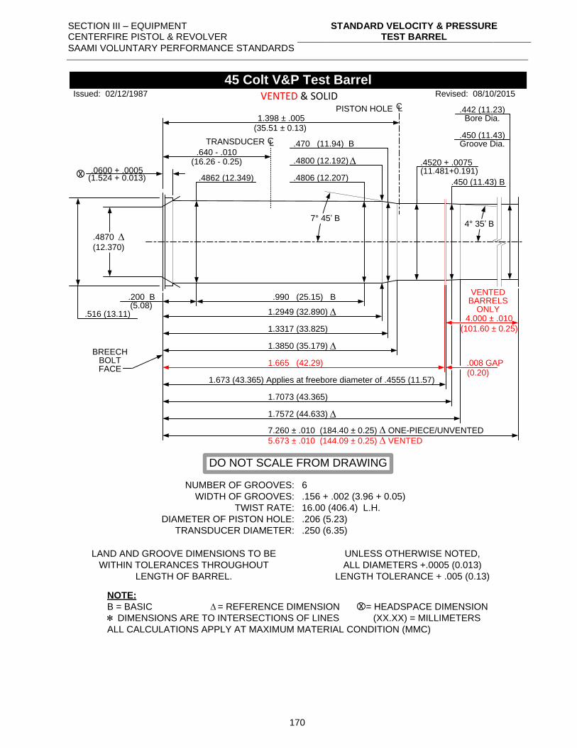
SECTION III – EQUIPMENT CENTERFIRE PISTOL & REVOLVER
STANDARD VELOCITY & PRESSURE TEST BARREL
SAAMI VOLUNTARY PERFORMANCE STANDARDS
170
.0600 + .0005.4806 (12.207)
.990 (25.15) B.200 B(5.08)
1.2949 (32.890)
1.3317 (33.825)
.442 (11.23)
.450 (11.43)
Bore Dia.
Groove Dia.
.516 (13.11)
NUMBER OF GROOVES:
WIDTH OF GROOVES:
TWIST RATE:
DIAMETER OF PISTON HOLE:
TRANSDUCER DIAMETER:
6
.156 + .002 (3.96 + 0.05)
16.00 (406.4) L.H.
.206 (5.23)
.250 (6.35)
LAND AND GROOVE DIMENSIONS TO BE
WITHIN TOLERANCES THROUGHOUT
LENGTH OF BARREL.
UNLESS OTHERWISE NOTED,
ALL DIAMETERS +.0005 (0.013)
LENGTH TOLERANCE + .005 (0.13)
NOTE:
B = BASIC = REFERENCE DIMENSION = HEADSPACE DIMENSION
DIMENSIONS ARE TO INTERSECTIONS OF LINES (XX.XX) = MILLIMETERS
ALL CALCULATIONS APPLY AT MAXIMUM MATERIAL CONDITION (MMC)
45 Colt V&P Test Barrel
BREECHBOLTFACE
.4520 + .0075(11.481+0.191)
.470 (11.94) B
.4862 (12.349)
1.665 (42.29)
PISTON HOLE CL
1.398 ± .005
.450 (11.43) B
1.3850 (35.179)
1.7073 (43.365)
1.7572 (44.633)
7.260 ± .010 (184.40 ± 0.25) ONE-PIECE/UNVENTED
5.673 ± .010 (144.09 ± 0.25) VENTED
.008 GAP
4.000 ± .010
(101.60 ± 0.25)
7° 45’ B
VENTED & SOLID
(35.51 ± 0.13)
(0.20)
(1.524 + 0.013)
Issued: 02/12/1987 Revised: 08/10/2015
DO NOT SCALE FROM DRAWING
.4800 (12.192)
4° 35’ B
.4870
(12.370)
.640 - .010
TRANSDUCER
(16.26 - 0.25)
CL
1.673 (43.365) Applies at freebore diameter of .4555 (11.57)
VENTEDBARRELS
ONLY
X
X
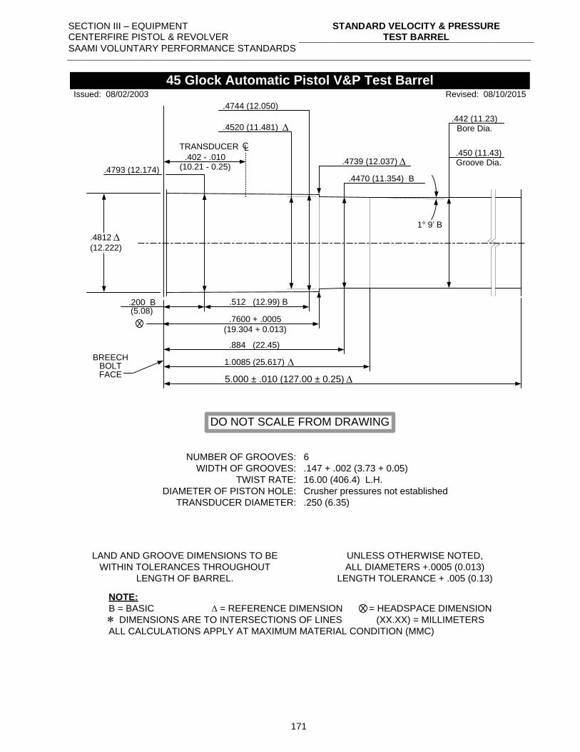
SECTION III – EQUIPMENT CENTERFIRE PISTOL & REVOLVER
STANDARD VELOCITY & PRESSURE TEST BARREL
SAAMI VOLUNTARY PERFORMANCE STANDARDS
171
.4520 (11.481)
.4739 (12.037)
.512 (12.99) B.200 B(5.08)
.7600 + .0005
(19.304 + 0.013)
.884 (22.45)
1.0085 (25.617)
X
.442 (11.23)
.450 (11.43)
Bore Dia.
Groove Dia.
.4812
(12.222)
NUMBER OF GROOVES:
WIDTH OF GROOVES:
TWIST RATE:
DIAMETER OF PISTON HOLE:
TRANSDUCER DIAMETER:
6
.147 + .002 (3.73 + 0.05)
16.00 (406.4) L.H.
Crusher pressures not established
.250 (6.35)
LAND AND GROOVE DIMENSIONS TO BE
WITHIN TOLERANCES THROUGHOUT
LENGTH OF BARREL.
UNLESS OTHERWISE NOTED,
ALL DIAMETERS +.0005 (0.013)
LENGTH TOLERANCE + .005 (0.13)
NOTE:
B = BASIC = REFERENCE DIMENSION = HEADSPACE DIMENSION
DIMENSIONS ARE TO INTERSECTIONS OF LINES (XX.XX) = MILLIMETERS
ALL CALCULATIONS APPLY AT MAXIMUM MATERIAL CONDITION (MMC)
X
45 Glock Automatic Pistol V&P Test Barrel
BREECHBOLTFACE
Revised: 08/10/2015
.4470 (11.354) B
Issued: 08/02/2003
.4744 (12.050)
DO NOT SCALE FROM DRAWING
.4793 (12.174)
.402 - .010
TRANSDUCER CL
(10.21 - 0.25)
1° 9’ B
5.000 ± .010 (127.00 ± 0.25)
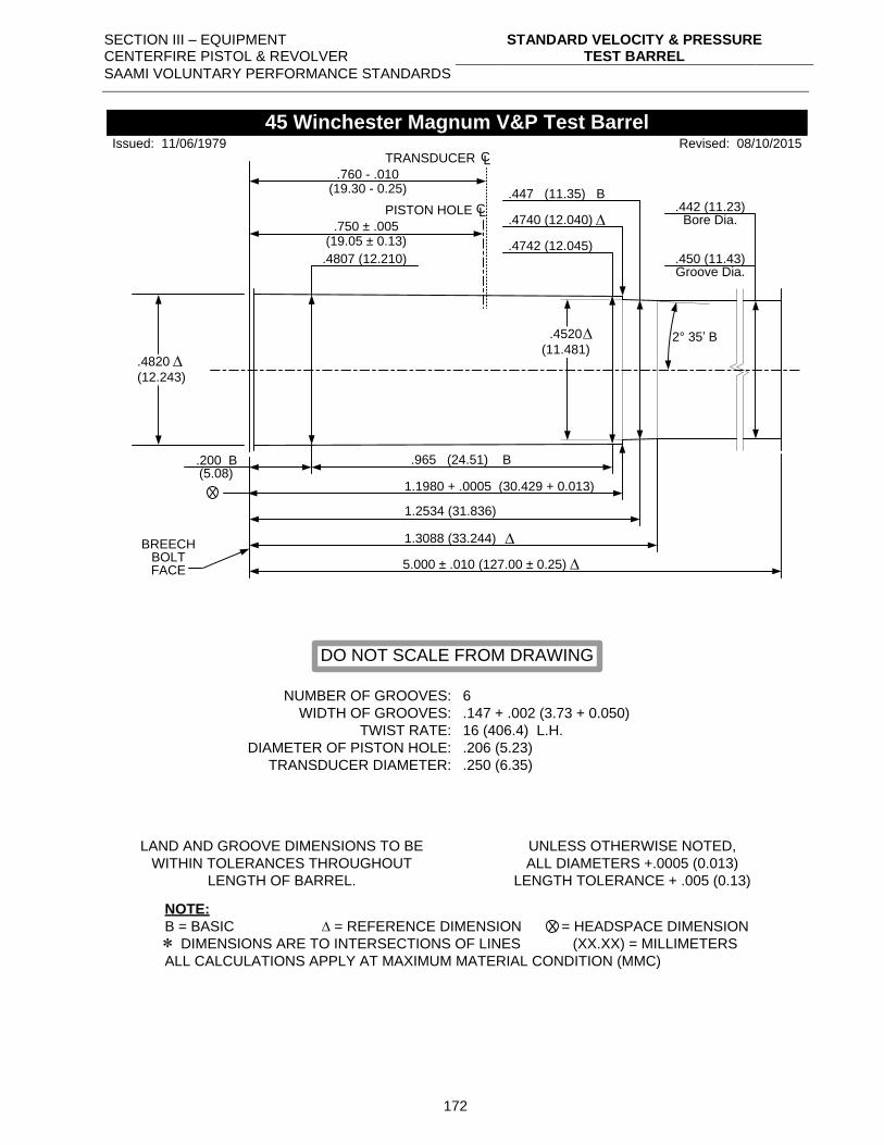
SECTION III – EQUIPMENT CENTERFIRE PISTOL & REVOLVER
STANDARD VELOCITY & PRESSURE TEST BARREL
SAAMI VOLUNTARY PERFORMANCE STANDARDS
172
.4742 (12.045)
.4740 (12.040)
2° 35’ B
.965 (24.51) B.200 B(5.08)
1.1980 + .0005 (30.429 + 0.013)
1.3088 (33.244)
X
.442 (11.23)
.450 (11.43)
Bore Dia.
Groove Dia.
.4820
(12.243)
NUMBER OF GROOVES:
WIDTH OF GROOVES:
TWIST RATE:
DIAMETER OF PISTON HOLE:
TRANSDUCER DIAMETER:
6
.147 + .002 (3.73 + 0.050)
16 (406.4) L.H.
.206 (5.23)
.250 (6.35)
LAND AND GROOVE DIMENSIONS TO BE
WITHIN TOLERANCES THROUGHOUT
LENGTH OF BARREL.
UNLESS OTHERWISE NOTED,
ALL DIAMETERS +.0005 (0.013)
LENGTH TOLERANCE + .005 (0.13)
NOTE:
B = BASIC = REFERENCE DIMENSION = HEADSPACE DIMENSION
DIMENSIONS ARE TO INTERSECTIONS OF LINES (XX.XX) = MILLIMETERS
ALL CALCULATIONS APPLY AT MAXIMUM MATERIAL CONDITION (MMC)
X
45 Winchester Magnum V&P Test Barrel
BREECHBOLTFACE
Revised: 08/10/2015
.447 (11.35) B
Issued: 11/06/1979
DO NOT SCALE FROM DRAWING
.4807 (12.210)
PISTON HOLE CL.750 ± .005
(19.05 ± 0.13)
.4520
(11.481)
.760 - .010
TRANSDUCER CL
(19.30 - 0.25)
1.2534 (31.836)
5.000 ± .010 (127.00 ± 0.25)
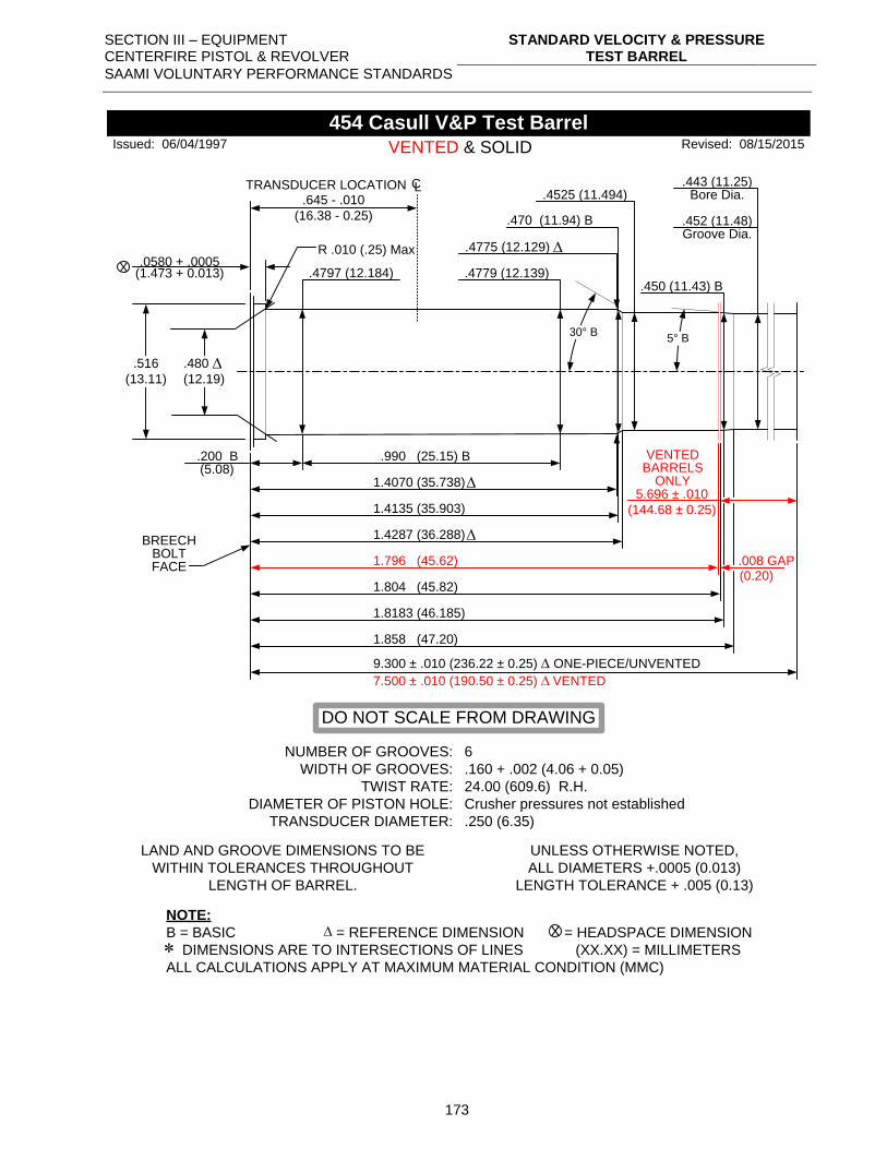
SECTION III – EQUIPMENT CENTERFIRE PISTOL & REVOLVER
STANDARD VELOCITY & PRESSURE TEST BARREL
SAAMI VOLUNTARY PERFORMANCE STANDARDS
173
.0580 + .0005.4779 (12.139)
.990 (25.15) B.200 B(5.08)
1.4070 (35.738)
1.4135 (35.903)
X
.443 (11.25)
.452 (11.48)
Bore Dia.
Groove Dia.
.516
(13.11)
NUMBER OF GROOVES:
WIDTH OF GROOVES:
TWIST RATE:
DIAMETER OF PISTON HOLE:
TRANSDUCER DIAMETER:
6
.160 + .002 (4.06 + 0.05)
24.00 (609.6) R.H.
Crusher pressures not established
.250 (6.35)
LAND AND GROOVE DIMENSIONS TO BE
WITHIN TOLERANCES THROUGHOUT
LENGTH OF BARREL.
UNLESS OTHERWISE NOTED,
ALL DIAMETERS +.0005 (0.013)
LENGTH TOLERANCE + .005 (0.13)
NOTE:
B = BASIC = REFERENCE DIMENSION = HEADSPACE DIMENSION
DIMENSIONS ARE TO INTERSECTIONS OF LINES (XX.XX) = MILLIMETERS
ALL CALCULATIONS APPLY AT MAXIMUM MATERIAL CONDITION (MMC)
X
454 Casull V&P Test Barrel
BREECHBOLTFACE
.470 (11.94) B
.4797 (12.184)
1.796 (45.62)
.4525 (11.494)
1.4287 (36.288)
.008 GAP
5.696 ± .010
(144.68 ± 0.25)
30° B
VENTED & SOLID
(0.20)
(1.473 + 0.013)
Issued: 06/04/1997 Revised: 08/15/2015
DO NOT SCALE FROM DRAWING
.4775 (12.129)
5° B
9.300 ± .010 (236.22 ± 0.25) ONE-PIECE/UNVENTED
7.500 ± .010 (190.50 ± 0.25) VENTED
R .010 (.25) Max
1.8183 (46.185)
1.858 (47.20)
.480
(12.19)
.450 (11.43) B
.645 - .010
(16.38 - 0.25)
TRANSDUCER LOCATION CL
VENTEDBARRELS
ONLY
1.804 (45.82)
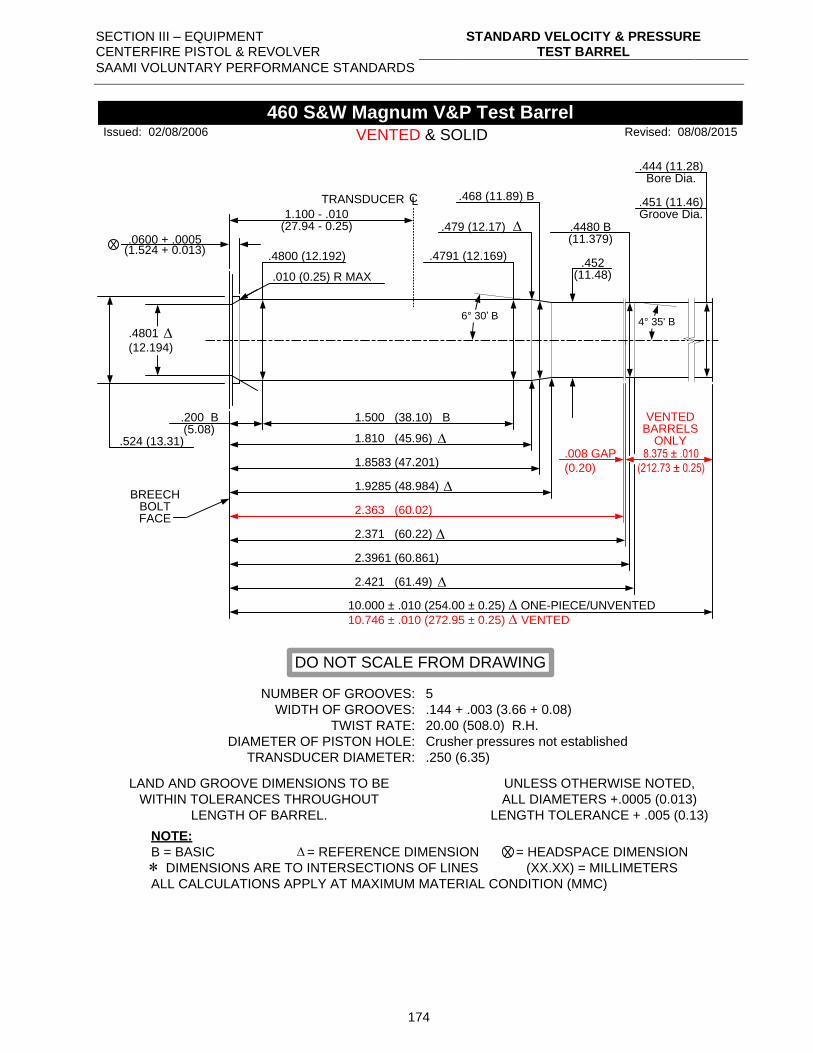
SECTION III – EQUIPMENT CENTERFIRE PISTOL & REVOLVER
STANDARD VELOCITY & PRESSURE TEST BARREL
SAAMI VOLUNTARY PERFORMANCE STANDARDS
174
.0600 + .0005
.4791 (12.169)
1.500 (38.10) B.200 B(5.08)
1.810 (45.96)
1.8583 (47.201)
X
.444 (11.28)
.451 (11.46)
Bore Dia.
Groove Dia.
.524 (13.31)
NUMBER OF GROOVES:
WIDTH OF GROOVES:
TWIST RATE:
DIAMETER OF PISTON HOLE:
TRANSDUCER DIAMETER:
5
.144 + .003 (3.66 + 0.08)
20.00 (508.0) R.H.
Crusher pressures not established
.250 (6.35)
LAND AND GROOVE DIMENSIONS TO BE
WITHIN TOLERANCES THROUGHOUT
LENGTH OF BARREL.
UNLESS OTHERWISE NOTED,
ALL DIAMETERS +.0005 (0.013)
LENGTH TOLERANCE + .005 (0.13)
NOTE:
B = BASIC = REFERENCE DIMENSION = HEADSPACE DIMENSION
DIMENSIONS ARE TO INTERSECTIONS OF LINES (XX.XX) = MILLIMETERS
ALL CALCULATIONS APPLY AT MAXIMUM MATERIAL CONDITION (MMC)
X
460 S&W Magnum V&P Test Barrel
BREECHBOLTFACE
.452 (11.48)
.468 (11.89) B
.4800 (12.192)
2.363 (60.02)
.4480 B (11.379)
1.9285 (48.984)
2.3961 (60.861)
2.421 (61.49)
10.000 ± .010 (254.00 ± 0.25) ONE-PIECE/UNVENTED
10.746 ± .010 (272.95 ± 0.25) VENTED
.008 GAP
(0.20)
8.375 ± .010
(212.73 ± 0.25)
6° 30’ B
VENTED & SOLID
(1.524 + 0.013)
Issued: 02/08/2006 Revised: 08/08/2015
DO NOT SCALE FROM DRAWING
.479 (12.17)
4° 35' B
.4801
(12.194)
1.100 - .010
TRANSDUCER CL
(27.94 - 0.25)
.010 (0.25) R MAX
VENTEDBARRELS
ONLY
2.371 (60.22)
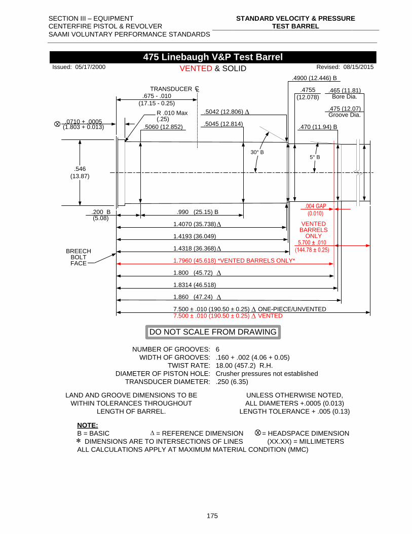
SECTION III – EQUIPMENT CENTERFIRE PISTOL & REVOLVER
STANDARD VELOCITY & PRESSURE TEST BARREL
SAAMI VOLUNTARY PERFORMANCE STANDARDS
175
.0710 + .0005 .5045 (12.814)
.990 (25.15) B.200 B(5.08)
1.4070 (35.738)
1.4193 (36.049)
X
.465 (11.81)
.475 (12.07)
Bore Dia.
Groove Dia.
.546
(13.87)
NUMBER OF GROOVES:
WIDTH OF GROOVES:
TWIST RATE:
DIAMETER OF PISTON HOLE:
TRANSDUCER DIAMETER:
6
.160 + .002 (4.06 + 0.05)
18.00 (457.2) R.H.
Crusher pressures not established
.250 (6.35)
LAND AND GROOVE DIMENSIONS TO BE
WITHIN TOLERANCES THROUGHOUT
LENGTH OF BARREL.
UNLESS OTHERWISE NOTED,
ALL DIAMETERS +.0005 (0.013)
LENGTH TOLERANCE + .005 (0.13)
NOTE:
B = BASIC = REFERENCE DIMENSION = HEADSPACE DIMENSION
DIMENSIONS ARE TO INTERSECTIONS OF LINES (XX.XX) = MILLIMETERS
ALL CALCULATIONS APPLY AT MAXIMUM MATERIAL CONDITION (MMC)
X
475 Linebaugh V&P Test Barrel
BREECHBOLTFACE
.4900 (12.446) B
.5060 (12.852)
1.7960 (45.618) *VENTED BARRELS ONLY*
.4755
(12.078)
1.4318 (36.368)
5.700 ± .010
(144.78 ± 0.25)
30° B
(1.803 + 0.013)
Issued: 05/17/2000 Revised: 08/15/2015
DO NOT SCALE FROM DRAWING
.5042 (12.806)
5° B
7.500 ± .010 (190.50 ± 0.25) VENTED
R .010 Max (.25)
.675 - .010
(17.15 - 0.25)
TRANSDUCER CL
VENTED & SOLID
.004 GAP
(0.010)
VENTEDBARRELS
ONLY
7.500 ± .010 (190.50 ± 0.25) ONE-PIECE/UNVENTED
1.800 (45.72)
1.8314 (46.518)
1.860 (47.24)
.470 (11.94) B
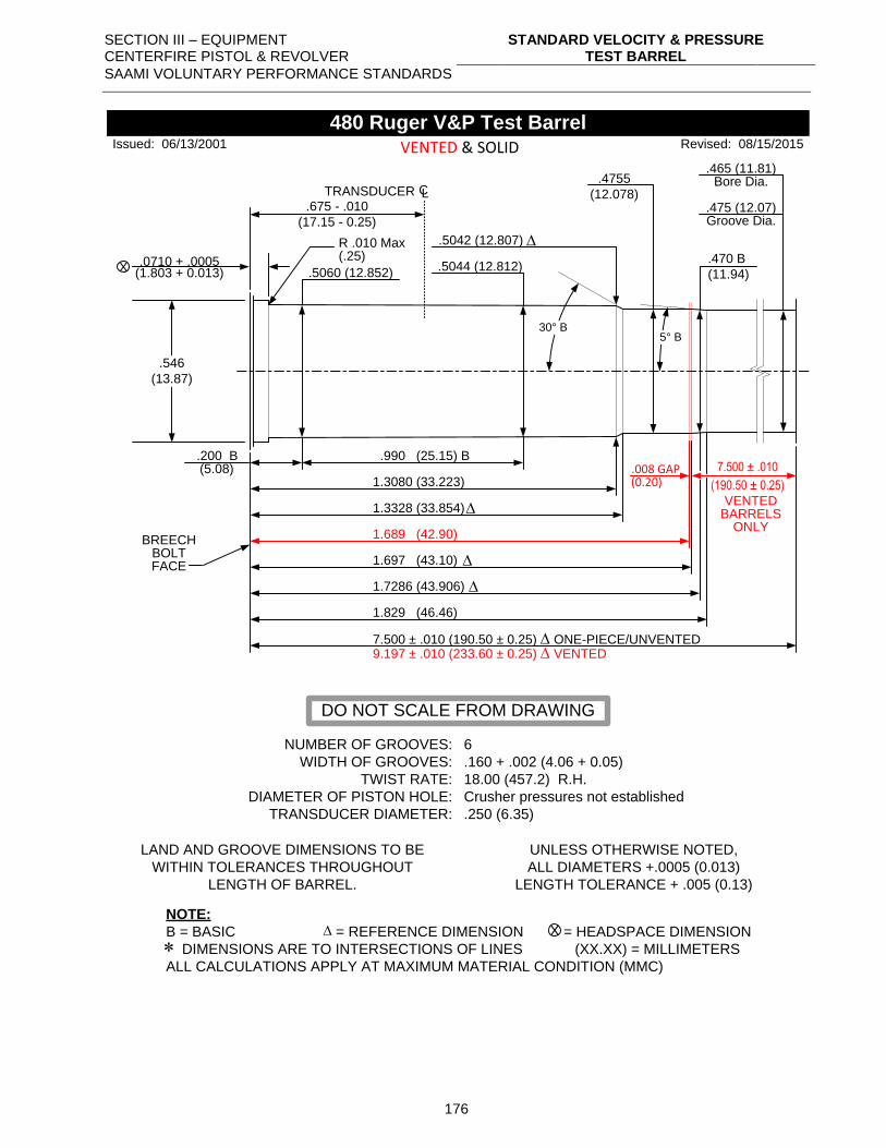
SECTION III – EQUIPMENT CENTERFIRE PISTOL & REVOLVER
STANDARD VELOCITY & PRESSURE TEST BARREL
SAAMI VOLUNTARY PERFORMANCE STANDARDS
176
.0710 + .0005 .5044 (12.812)
.990 (25.15) B.200 B(5.08)
1.3080 (33.223)
1.3328 (33.854)
X
.465 (11.81)
.475 (12.07)
Bore Dia.
Groove Dia.
.546
(13.87)
NUMBER OF GROOVES:
WIDTH OF GROOVES:
TWIST RATE:
DIAMETER OF PISTON HOLE:
TRANSDUCER DIAMETER:
6
.160 + .002 (4.06 + 0.05)
18.00 (457.2) R.H.
Crusher pressures not established
.250 (6.35)
LAND AND GROOVE DIMENSIONS TO BE
WITHIN TOLERANCES THROUGHOUT
LENGTH OF BARREL.
UNLESS OTHERWISE NOTED,
ALL DIAMETERS +.0005 (0.013)
LENGTH TOLERANCE + .005 (0.13)
NOTE:
B = BASIC = REFERENCE DIMENSION = HEADSPACE DIMENSION
DIMENSIONS ARE TO INTERSECTIONS OF LINES (XX.XX) = MILLIMETERS
ALL CALCULATIONS APPLY AT MAXIMUM MATERIAL CONDITION (MMC)
X
480 Ruger V&P Test Barrel
BREECHBOLTFACE
.5060 (12.852)
1.7286 (43.906)
.4755
(12.078)
1.697 (43.10)
.008 GAP 7.500 ± .010
(190.50 ± 0.25)
30° B
VENTED & SOLID
(0.20)
(1.803 + 0.013)
Issued: 06/13/2001 Revised: 08/15/2015
DO NOT SCALE FROM DRAWING
.5042 (12.807)
5° B
9.197 ± .010 (233.60 ± 0.25) VENTED
R .010 Max (.25)
1.689 (42.90)
.675 - .010
(17.15 - 0.25)
TRANSDUCER CL
VENTEDBARRELS
ONLY
7.500 ± .010 (190.50 ± 0.25) ONE-PIECE/UNVENTED
1.829 (46.46)
.470 B
(11.94)
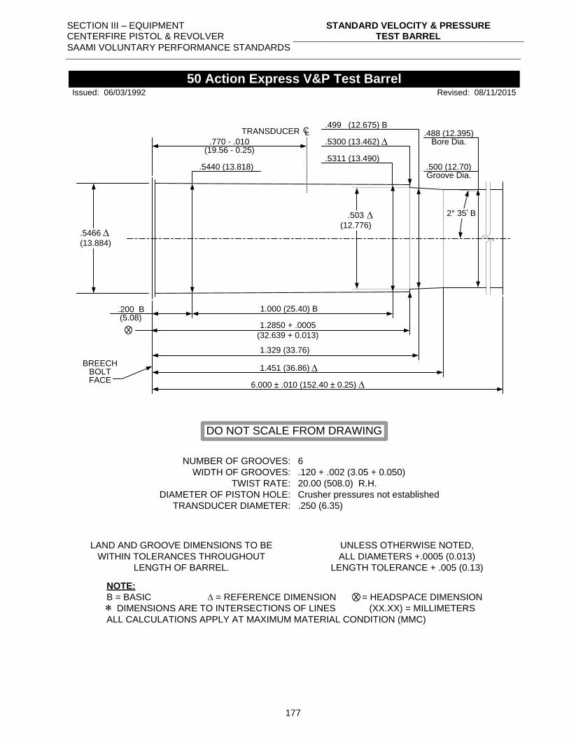
SECTION III – EQUIPMENT CENTERFIRE PISTOL & REVOLVER
STANDARD VELOCITY & PRESSURE TEST BARREL
SAAMI VOLUNTARY PERFORMANCE STANDARDS
177
.5311 (13.490)
.5300 (13.462)
1.000 (25.40) B.200 B(5.08)
1.2850 + .0005
(32.639 + 0.013)
1.329 (33.76)
1.451 (36.86)
X
.488 (12.395)
.500 (12.70)
Bore Dia.
Groove Dia.
.5466
(13.884)
NUMBER OF GROOVES:
WIDTH OF GROOVES:
TWIST RATE:
DIAMETER OF PISTON HOLE:
TRANSDUCER DIAMETER:
6
.120 + .002 (3.05 + 0.050)
20.00 (508.0) R.H.
Crusher pressures not established
.250 (6.35)
LAND AND GROOVE DIMENSIONS TO BE
WITHIN TOLERANCES THROUGHOUT
LENGTH OF BARREL.
UNLESS OTHERWISE NOTED,
ALL DIAMETERS +.0005 (0.013)
LENGTH TOLERANCE + .005 (0.13)
NOTE:
B = BASIC = REFERENCE DIMENSION = HEADSPACE DIMENSION
DIMENSIONS ARE TO INTERSECTIONS OF LINES (XX.XX) = MILLIMETERS
ALL CALCULATIONS APPLY AT MAXIMUM MATERIAL CONDITION (MMC)
X
50 Action Express V&P Test Barrel
BREECHBOLTFACE
Revised: 08/11/2015
.499 (12.675) B
Issued: 06/03/1992
DO NOT SCALE FROM DRAWING
.5440 (13.818)
.503
(12.776)
.770 - .010
TRANSDUCER CL
(19.56 - 0.25)
2° 35’ B
6.000 ± .010 (152.40 ± 0.25)
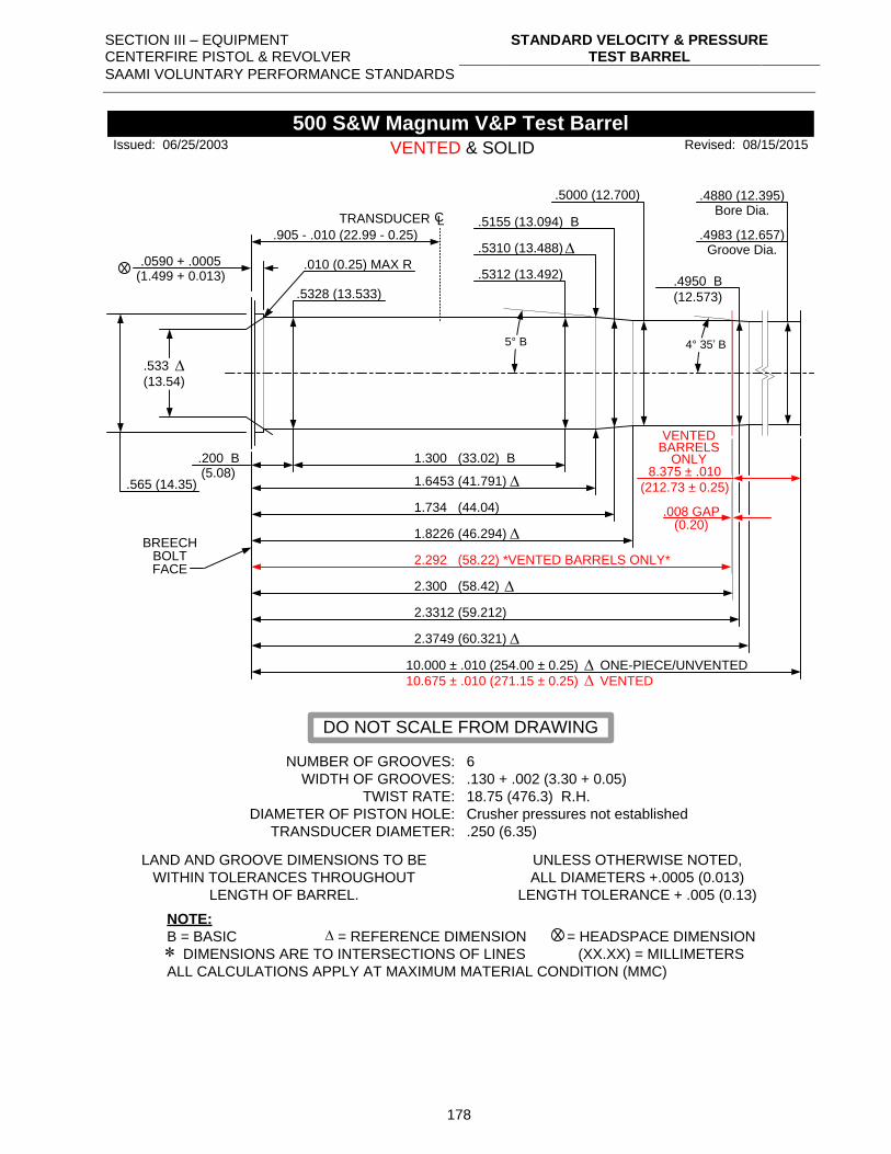
SECTION III – EQUIPMENT CENTERFIRE PISTOL & REVOLVER
STANDARD VELOCITY & PRESSURE TEST BARREL
SAAMI VOLUNTARY PERFORMANCE STANDARDS
178
.0590 + .0005.5312 (13.492)
.200 B(5.08)
1.6453 (41.791)
1.734 (44.04)
X
.4880 (12.395)
.4983 (12.657)
Bore Dia.
Groove Dia.
.565 (14.35)
NUMBER OF GROOVES:
WIDTH OF GROOVES:
TWIST RATE:
DIAMETER OF PISTON HOLE:
TRANSDUCER DIAMETER:
6
.130 + .002 (3.30 + 0.05)
18.75 (476.3) R.H.
Crusher pressures not established
.250 (6.35)
LAND AND GROOVE DIMENSIONS TO BE
WITHIN TOLERANCES THROUGHOUT
LENGTH OF BARREL.
UNLESS OTHERWISE NOTED,
ALL DIAMETERS +.0005 (0.013)
LENGTH TOLERANCE + .005 (0.13)
NOTE:
B = BASIC = REFERENCE DIMENSION = HEADSPACE DIMENSION
DIMENSIONS ARE TO INTERSECTIONS OF LINES (XX.XX) = MILLIMETERS
ALL CALCULATIONS APPLY AT MAXIMUM MATERIAL CONDITION (MMC)
X
500 S&W Magnum V&P Test Barrel
BREECHBOLTFACE
.5000 (12.700)
.5155 (13.094) B
.5328 (13.533)
2.292 (58.22) *VENTED BARRELS ONLY*
.4950 B
(12.573)
1.8226 (46.294)
2.3312 (59.212)
2.3749 (60.321)
10.000 ± .010 (254.00 ± 0.25) ONE-PIECE/UNVENTED
10.675 ± .010 (271.15 ± 0.25) VENTED
8.375 ± .010
(212.73 ± 0.25)
5° B
VENTED & SOLID
(1.499 + 0.013)
Issued: 06/25/2003 Revised: 08/15/2015
DO NOT SCALE FROM DRAWING
.5310 (13.488)
4° 35’ B
.533
(13.54)
.905 - .010 (22.99 - 0.25)
TRANSDUCER CL
1.300 (33.02) B
.010 (0.25) MAX R
VENTEDBARRELS
ONLY
.008 GAP(0.20)
2.300 (58.42)
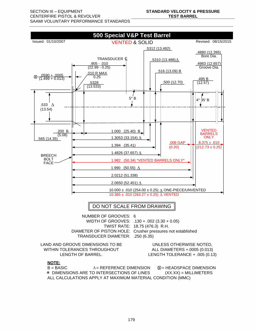
SECTION III – EQUIPMENT CENTERFIRE PISTOL & REVOLVER
STANDARD VELOCITY & PRESSURE TEST BARREL
SAAMI VOLUNTARY PERFORMANCE STANDARDS
179
.0590 + .0005
.5312 (13.492)
1.000 (25.40) B.200 B(5.08)
1.3053 (33.154)
1.394 (35.41)
X
.4880 (12.395)
.4983 (12.657)
Bore Dia.
Groove Dia.
.565 (14.35)
NUMBER OF GROOVES:
WIDTH OF GROOVES:
TWIST RATE:
DIAMETER OF PISTON HOLE:
TRANSDUCER DIAMETER:
6
.130 + .002 (3.30 + 0.05)
18.75 (476.3) R.H.
Crusher pressures not established
.250 (6.35)
LAND AND GROOVE DIMENSIONS TO BE
WITHIN TOLERANCES THROUGHOUT
LENGTH OF BARREL.
UNLESS OTHERWISE NOTED,
ALL DIAMETERS +.0005 (0.013)
LENGTH TOLERANCE + .005 (0.13)
NOTE:
B = BASIC = REFERENCE DIMENSION = HEADSPACE DIMENSION
DIMENSIONS ARE TO INTERSECTIONS OF LINES (XX.XX) = MILLIMETERS
ALL CALCULATIONS APPLY AT MAXIMUM MATERIAL CONDITION (MMC)
X
500 Special V&P Test Barrel
BREECHBOLTFACE
.500 (12.70)
.516 (13.09) B
.5328(13.533)
1.982 (50.34) *VENTED BARRELS ONLY*
.495 B (12.57)
1.4826 (37.657)
2.0212 (51.338)
2.0650 (52.451)
10.000 ± .010 (254.00 ± 0.25) ONE-PIECE/UNVENTED
10.365 ± .010 (263.27 ± 0.25) VENTED
.008 GAP
(0.20)
8.375 ± .010
(212.73 ± 0.25)
5° B
VENTED & SOLID
(1.499 + 0.013)
Issued: 01/10/2007 Revised: 08/15/2015
DO NOT SCALE FROM DRAWING
.5310 (13.488)
4° 35' B
.533
(13.54)
.905 - .010
TRANSDUCER CL
(22.99 - 0.25)
.010 R MAX0.25
VENTEDBARRELS
ONLY
1.990 (50.55)
SECTION IV – DEFINITIVE PROOF LOADS CENTERFIRE PISTOL & REVOLVER
DEFINITION AND PURPOSE
SAAMI VOLUNTARY PERFORMANCE STANDARDS
180
DEFINITION AND PURPOSE
SAAMI Definitive Proof cartridges are cartridges commercially loaded by SAAMI member
companies which develop pressure substantially exceeding those developed by normal service loads.
The pressure levels are designed to assure gun safety when using ammunition loaded to service
pressures in accordance with accepted American practices.
Proof cartridges are designed to stress firearms components which contain the cartridge in order to
assure safety in the recommended use of the firearm during its service life.
It is important from the safety standpoint that Definitive Proof cartridges be used only for the proof
of firearms. Adequate precaution must be taken to protect personnel performing firearms proof
testing.
Definitive Proof cartridges for revolvers should be loaded with the heaviest bullet for the particular
cartridge except where jacketed bullets not more than 25% lighter than the heaviest lead bullet are
available. An appropriate powder which will stress the revolver cylinder should be used.
The supply of Definitive Proof cartridges will be the responsibility of the company that first
introduced that particular caliber to the Institute. Definitive Proof Cartridges should be loaded with
the heaviest bullet used at the time of introduction and the slowest powder which will meet the
pressure values indicated for that particular cartridge to maintain effective pressure-distance
relationship. Once established, the bullet weight for the proof load does not change unless the bullet
becomes obsolete. All changes in Definitive Proof cartridges bullet weight must be approved by the
Joint Technical Committee.
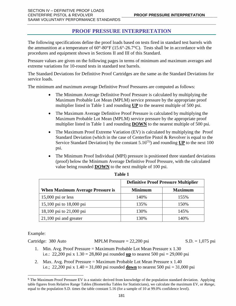
SECTION IV – DEFINITIVE PROOF LOADS CENTERFIRE PISTOL & REVOLVER
PROOF PRESSURE INTERPRETATION
SAAMI VOLUNTARY PERFORMANCE STANDARDS
181
PROOF PRESSURE INTERPRETATION
The following specifications define the proof loads based on tests fired in standard test barrels with
the ammunition at a temperature of 60°-80°F (15.6°-26.7°C). Tests shall be in accordance with the
procedures and equipment shown in Sections II and III of this Standard.
Pressure values are given on the following pages in terms of minimum and maximum averages and
extreme variations for 10-round tests in standard test barrels.
The Standard Deviations for Definitive Proof Cartridges are the same as the Standard Deviations for
service loads.
The minimum and maximum average Definitive Proof Pressures are computed as follows:
• The Minimum Average Definitive Proof Pressure is calculated by multiplying the
Maximum Probable Lot Mean (MPLM) service pressure by the appropriate proof
multiplier listed in Table 1 and rounding UP to the nearest multiple of 500 psi.
• The Maximum Average Definitive Proof Pressure is calculated by multiplying the
Maximum Probable Lot Mean (MPLM) service pressure by the appropriate proof
multiplier listed in Table 1 and rounding DOWN to the nearest multiple of 500 psi.
• The Maximum Proof Extreme Variation (EV) is calculated by multiplying the Proof
Standard Deviation (which in the case of Centerfire Pistol & Revolver is equal to the
Service Standard Deviation) by the constant 5.16(5)) and rounding UP to the next 100
psi.
• The Minimum Proof Individual (MPI) pressure is positioned three standard deviations
(proof) below the Minimum Average Definitive Proof Pressure, with the calculated
value being rounded DOWN to the next multiple of 100 psi.
Table 1
Definitive Proof Pressure Multiplier
When Maximum Average Pressure is Minimum Maximum
15,000 psi or less 140% 155%
15,100 psi to 18,000 psi 135% 150%
18,100 psi to 21,000 psi 130% 145%
21,100 psi and greater 130% 140%
Example:
Cartridge: 380 Auto MPLM Pressure = 22,200 psi S.D. = 1,075 psi
1. Min. Avg. Proof Pressure = Maximum Probable Lot Mean Pressure x 1.30
i.e.: 22,200 psi x 1.30 = 28,860 psi rounded up to nearest 500 psi = 29,000 psi
2. Max. Avg. Proof Pressure = Maximum Probable Lot Mean Pressure x 1.40
i.e.; 22,200 psi x 1.40 = 31,080 psi rounded down to nearest 500 psi = 31,000 psi
5 The Maximum Proof Pressure EV is a statistic derived from knowledge of the population standard deviation. Applying
table figures from Relative Range Tables (Biometrika Tables for Statisticians), we calculate the maximum EV, or Range,
equal to the population S.D. times the table constant 5.16 (for a sample of 10 at 99.0% confidence level).
SECTION IV – DEFINITIVE PROOF LOADS CENTERFIRE PISTOL & REVOLVER
PROOF PRESSURE INTERPRETATION
SAAMI VOLUNTARY PERFORMANCE STANDARDS
182
3. Max. Proof E.V. = Service Standard Deviation x 5.16.
i.e.: 1,075 psi x 5.16 = 5,547 psi rounded up to next 100 psi = 5,600 psi.
4. Minimum Proof Individual = Min. Avg. Proof Pressure – (3 x (PROOF))
i.e., 29,000 psi – (3 x 1,075 psi) = 25,775 psi rounded down to next 100 psi = 25,700 psi.
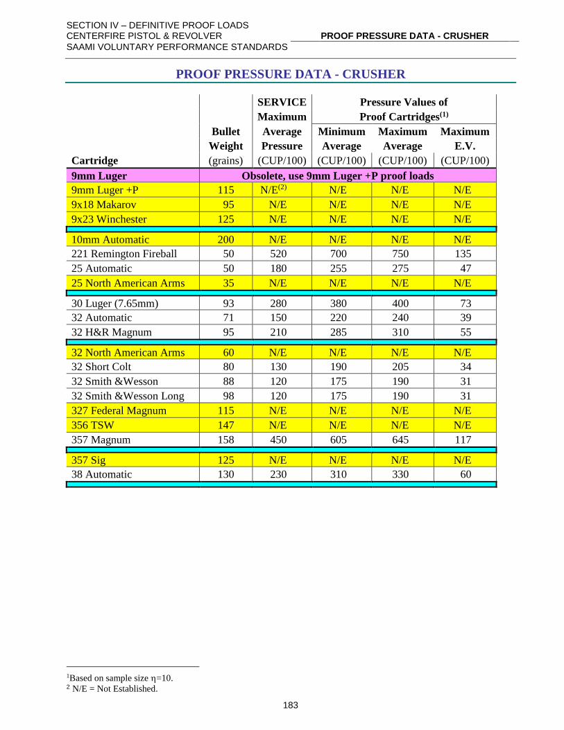
SECTION IV – DEFINITIVE PROOF LOADS CENTERFIRE PISTOL & REVOLVER
PROOF PRESSURE DATA - CRUSHER
SAAMI VOLUNTARY PERFORMANCE STANDARDS
183
PROOF PRESSURE DATA - CRUSHER
SERVICE Pressure Values of
Maximum Proof Cartridges(1)
Bullet Average Minimum Maximum Maximum
Weight Pressure Average Average E.V.
Cartridge (grains) (CUP/100) (CUP/100) (CUP/100) (CUP/100)
9mm Luger Obsolete, use 9mm Luger +P proof loads
9mm Luger +P 115 N/E(2) N/E N/E N/E
9x18 Makarov 95 N/E N/E N/E N/E
9x23 Winchester 125 N/E N/E N/E N/E
10mm Automatic 200 N/E N/E N/E N/E
221 Remington Fireball 50 520 700 750 135
25 Automatic 50 180 255 275 47
25 North American Arms 35 N/E N/E N/E N/E
30 Luger (7.65mm) 93 280 380 400 73
32 Automatic 71 150 220 240 39
32 H&R Magnum 95 210 285 310 55
32 North American Arms 60 N/E N/E N/E N/E
32 Short Colt 80 130 190 205 34
32 Smith &Wesson 88 120 175 190 31
32 Smith &Wesson Long 98 120 175 190 31
327 Federal Magnum 115 N/E N/E N/E N/E
356 TSW 147 N/E N/E N/E N/E
357 Magnum 158 450 605 645 117
357 Sig 125 N/E N/E N/E N/E
38 Automatic 130 230 310 330 60
1Based on sample size =10. 2 N/E = Not Established.
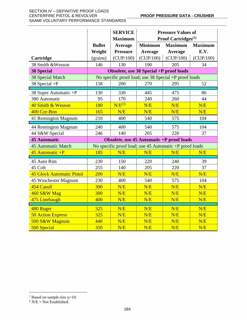
SECTION IV – DEFINITIVE PROOF LOADS CENTERFIRE PISTOL & REVOLVER
PROOF PRESSURE DATA - CRUSHER
SAAMI VOLUNTARY PERFORMANCE STANDARDS
184
SERVICE Pressure Values of
Maximum Proof Cartridges(1)
Bullet Average Minimum Maximum Maximum
Weight Pressure Average Average E.V.
Cartridge (grains) (CUP/100) (CUP/100) (CUP/100) (CUP/100)
38 Smith &Wesson 146 130 190 205 34
38 Special Obsolete, use 38 Special +P proof loads
38 Special Match No specific proof load; use 38 Special +P proof loads
38 Special +P 158 200 270 295 52
38 Super Automatic +P 130 330 445 475 86
380 Automatic 95 170 240 260 44
40 Smith & Wesson 180 N/E(2) N/E N/E N/E
400 Cor-Bon 165 N/E N/E N/E N/E
41 Remington Magnum 210 400 540 575 104
44 Remington Magnum 240 400 540 575 104
44 S&W Special 246 140 205 220 37
45 Automatic Obsolete, use 45 Automatic +P proof loads
45 Automatic Match No specific proof load; use 45 Automatic +P proof loads
45 Automatic +P 185 N/E N/E N/E N/E
45 Auto Rim 230 150 220 240 39
45 Colt 255 140 205 220 37
45 Glock Automatic Pistol 200 N/E N/E N/E N/E
45 Winchester Magnum 230 400 540 575 104
454 Casull 300 N/E N/E N/E N/E
460 S&W Mag 300 N/E N/E N/E N/E
475 Linebaugh 400 N/E N/E N/E N/E
480 Ruger 325 N/E N/E N/E N/E
50 Action Express 325 N/E N/E N/E N/E
500 S&W Magnum 440 N/E N/E N/E N/E
500 Special 350 N/E N/E N/E N/E
1 Based on sample size =10. 2 N/E = Not Established.
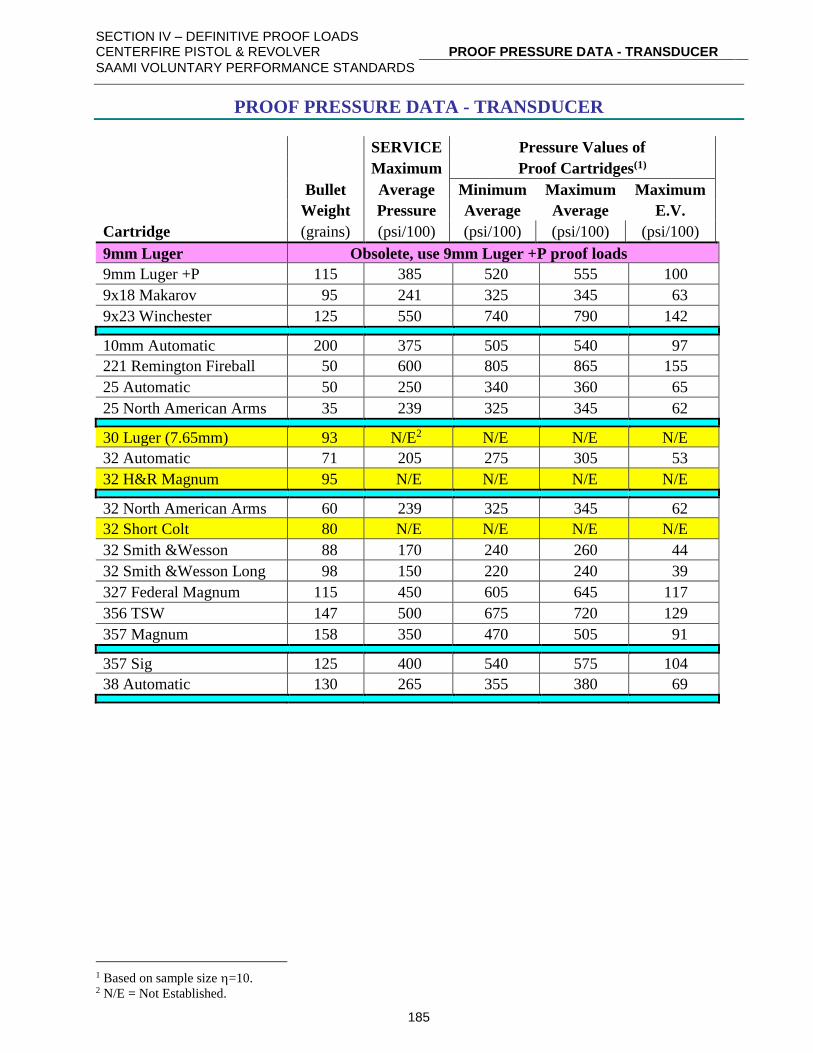
SECTION IV – DEFINITIVE PROOF LOADS CENTERFIRE PISTOL & REVOLVER
PROOF PRESSURE DATA - TRANSDUCER
SAAMI VOLUNTARY PERFORMANCE STANDARDS
185
PROOF PRESSURE DATA - TRANSDUCER
SERVICE Pressure Values of
Maximum Proof Cartridges(1)
Bullet Average Minimum Maximum Maximum
Weight Pressure Average Average E.V.
Cartridge (grains) (psi/100) (psi/100) (psi/100) (psi/100)
9mm Luger Obsolete, use 9mm Luger +P proof loads
9mm Luger +P 115 385 520 555 100
9x18 Makarov 95 241 325 345 63
9x23 Winchester 125 550 740 790 142
10mm Automatic 200 375 505 540 97
221 Remington Fireball 50 600 805 865 155
25 Automatic 50 250 340 360 65
25 North American Arms 35 239 325 345 62
30 Luger (7.65mm) 93 N/E2 N/E N/E N/E
32 Automatic 71 205 275 305 53
32 H&R Magnum 95 N/E N/E N/E N/E
32 North American Arms 60 239 325 345 62
32 Short Colt 80 N/E N/E N/E N/E
32 Smith &Wesson 88 170 240 260 44
32 Smith &Wesson Long 98 150 220 240 39
327 Federal Magnum 115 450 605 645 117
356 TSW 147 500 675 720 129
357 Magnum 158 350 470 505 91
357 Sig 125 400 540 575 104
38 Automatic 130 265 355 380 69
1 Based on sample size =10. 2 N/E = Not Established.
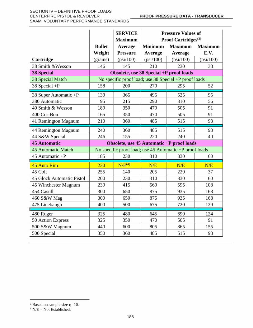
SECTION IV – DEFINITIVE PROOF LOADS CENTERFIRE PISTOL & REVOLVER
PROOF PRESSURE DATA - TRANSDUCER
SAAMI VOLUNTARY PERFORMANCE STANDARDS
186
SERVICE Pressure Values of
Maximum Proof Cartridges(3)
Bullet Average Minimum Maximum Maximum
Weight Pressure Average Average E.V.
Cartridge (grains) (psi/100) (psi/100) (psi/100) (psi/100)
38 Smith &Wesson 146 145 210 230 38
38 Special Obsolete, use 38 Special +P proof loads
38 Special Match No specific proof load; use 38 Special +P proof loads
38 Special +P 158 200 270 295 52
38 Super Automatic +P 130 365 495 525 95
380 Automatic 95 215 290 310 56
40 Smith & Wesson 180 350 470 505 91
400 Cor-Bon 165 350 470 505 91
41 Remington Magnum 210 360 485 515 93
44 Remington Magnum 240 360 485 515 93
44 S&W Special 246 155 220 240 40
45 Automatic Obsolete, use 45 Automatic +P proof loads
45 Automatic Match No specific proof load; use 45 Automatic +P proof loads
45 Automatic +P 185 230 310 330 60
45 Auto Rim 230 N/E(4) N/E N/E N/E
45 Colt 255 140 205 220 37
45 Glock Automatic Pistol 200 230 310 330 60
45 Winchester Magnum 230 415 560 595 108
454 Casull 300 650 875 935 168
460 S&W Mag 300 650 875 935 168
475 Linebaugh 400 500 675 720 129
480 Ruger 325 480 645 690 124
50 Action Express 325 350 470 505 91
500 S&W Magnum 440 600 805 865 155
500 Special 350 360 485 515 93
3 Based on sample size =10. 4 N/E = Not Established.
SECTION IV – DEFINITIVE PROOF LOADS CENTERFIRE PISTOL & REVOLVER
PROOF LOAD SUPPLY
SAAMI VOLUNTARY PERFORMANCE STANDARDS
187
PROOF LOAD SUPPLY
NOTE: Refer to Section III – page 130, Supplier Contact Information, for detailed information on
contacting the manufacturers of listed products and the SAAMI Technical Office.
Centerfire pistol and revolver Definitive Proof Loads should be used for one purpose only: the proof
testing of Centerfire pistols and revolvers.
A list of current suppliers may be obtained from the SAAMI Technical Office.
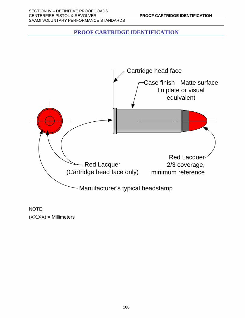
SECTION IV – DEFINITIVE PROOF LOADS CENTERFIRE PISTOL & REVOLVER
PROOF CARTRIDGE IDENTIFICATION
SAAMI VOLUNTARY PERFORMANCE STANDARDS
188
PROOF CARTRIDGE IDENTIFICATION
Red Lacquer
(Cartridge head face only)
Cartridge head face
Case finish - Matte surface
tin plate or visual
equivalent
Manufacturer’s typical headstamp
Red Lacquer
2/3 coverage,
minimum reference
NOTE:
(XX.XX) = Millimeters
SECTION IV – DEFINITIVE PROOF LOADS CENTERFIRE PISTOL & REVOLVER
DEFINITIVE PROOF PACKAGE IDENTIFICATION
SAAMI VOLUNTARY PERFORMANCE STANDARDS
189
DEFINITIVE PROOF PACKAGE IDENTIFICATION
HIGH PRESSURE PROOF LOADS
For Gun Manufacturers' Proof Test Use Only: Fire only from fixed rest with operator properly
protected from injury should the firearm be damaged. Purchaser should restrict proof loads to
manufacturing premises. To dispose of proof loads, contact producer for instructions.
DO NOT reload or dispose of fired proof shells in a manner that may make them available for
reloading. Failure to follow the foregoing can result in a personal injury.
Centerfire proof loads are identified by a tin-plated case (or visual equivalent) with red lacquer on
the bullet and case head face.
For consistent results, proof loads should be stored for 2 weeks at 70°F± 5° (21.1° ± 2.8°C), and
60% relative humidity before use.
"WARNING: KEEP OUT OF REACH OF CHILDREN"
(Red lettering on white background)