OPERATION/MAINTENANCE
INSTRUCTIONS
REGENERATIVE BLOWER
Series and BigBertha Blower Are registered trade marks of All-StarProducts.TMAll-Star HBTM TM
ISO9001
RoHSCompliantCE
Registered and approved by one or more of these standards agency
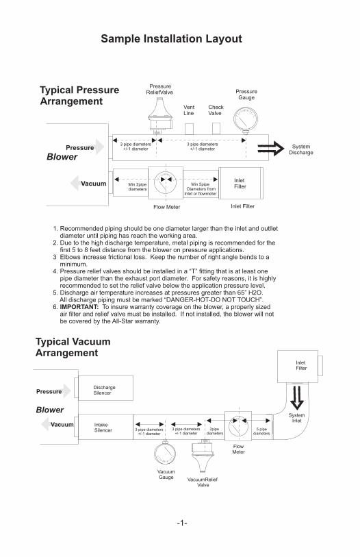
Sample Installation Layout
Typical VacuumArrangement
Typical Pressure
Blower
Arrangement
Vacuum
Pressure
InletFilter
Flow Meter Inlet Filter
VentLine
CheckValve
PressureReliefValve Pressure
Gauge
3 pipe diameters+/-1 diameter
3 pipe diameters+/-1 diameter System
Discharge
Min 2pipediameters
Min 5pipeDiameters from
Inlet or flowmeter
Blower
Vacuum
Pressure
IntakeSilencer
InletFilter
3 pipe diameters+/-1 diameter
SystemInlet
5 pipediameters
3 pipe diameters+/-1 diameter
2pipediameters
VacuumGauge VacuumRelief
Valve
FlowMeter
DischargeSilencer
-1-
1. Recommended piping should be one diameter larger than the inlet and outllet diameter until piping has reach the working area.2. Due to the high discharge temperature, metal piping is recommended for the first 5 to 8 feet distance from the blower on pressure applications.3 Elbows increase frictional loss. Keep the number of right angle bends to a minimum.4. Pressure relief valves should be installed in a “T” fitting that is at least one pipe diameter than the exhaust port diameter. For safety reasons, it is highly recommended to set the relief valve below the application pressure level.5. Discharge air temperature increases at pressures greater than 65” H2O. All discharge piping must be marked “DANGER-HOT-DO NOT TOUCH”.6. IMPORTANT: To insure warranty coverage on the blower, a properly sized air filter and relief valve must be installed. If not installed, the blower will not be covered by the All-Star warranty.
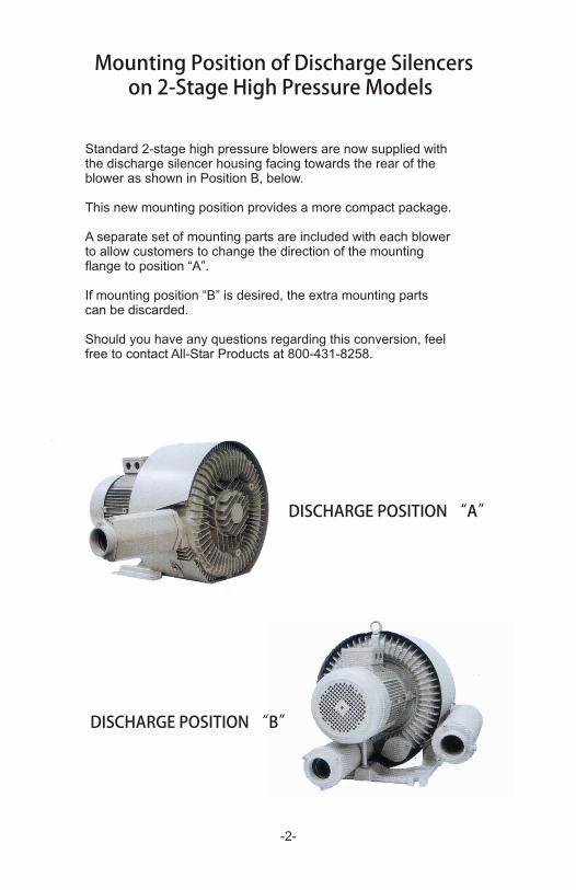
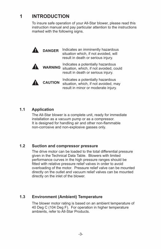
Mounting Position of Discharge Silencerson 2-Stage High Pressure Models
Standard 2-stage high pressure blowers are now supplied withthe discharge silencer housing facing towards the rear of theblower as shown in Position B, below.
This new mounting position provides a more compact package.
A separate set of mounting parts are included with each blowerto allow customers to change the direction of the mounting flange to position “A”.
If mounting position “B” is desired, the extra mounting parts can be discarded.
Should you have any questions regarding this conversion, feel free to contact All-Star Products at 800-431-8258.
DISCHARGE POSITION “A”
-2-
DISCHARGE POSITION “B”
1 INTRODUCTION
!
!
! DANGER
CAUTION
1.1 Application
1.2 Suction and compressor pressure
1.3 Environment (Ambient) Temperature
-3-
To insure safe operation of your All-Star blower, please read this instruction manual and pay particular attention to the instructionsmarked with the following signs.
Indicates an imminently hazardoussituation which, if not avoided, willresult in death or serious injury.
Indicates a potentially hazardoussituation, which, if not avoided, couldresult in death or serious injury.
WARNING
Indicates a potentially hazardoussituation, which, if not avoided, mayresult in minor or moderate injury.
The All-Star blower is a complete unit, ready for immediateinstallation as a vacuum pump or as a compressor.It is designed for handling air and other non-flammablenon-corrosive and non-explosive gasses only.
The drive motor can be loaded to the total differential pressuregiven in the Technical Data Table. Blowers with limitedperformance curves in the high pressure ranges should befitted with relative pressure relief valves in order to avoidoverloading of the motor. Pressure relief valve can be mounteddirectly on the outlet and vacuum relief valves can be mounteddirectly on the inlet of the blower.
The blower motor rating is based on an ambient temperature of 40 Deg C (104 Deg F). For operation in higher temperature ambients, refer to All-Star Products.
forma ific1.4 Per nce Spec ations
rP iorelMod
HB-1291-HB-129HB-129-12HB 129A-
HB-22 -19H -229B
HB329-1-HB- 932
HB-439
HB- 297HB-829HB-919
B-929HHB 939-
B 3326H -
HB-4 733H -434B 6
HB-6346HB 6355-HB- 3756
H -6455BHB-6475
HB-8310HB-8 153HB-8320
HB-8410HB 8415-
HP oV ltage Current
umMaximP fo aner rm ce
oundSdb(A)
WtlbsCFM * V S P *
.25
.25
.33
.33
.67
.67
1.11.1
2
3
8.511.5
152030
3.5
56.1
6.18.5
11.5
8.511.5
11.517.5
25
11.517.5
/61 0/115/230/23/60 08-230/460
11/60/1 5/2303/60/208-230/460
1/60/115/23060 03/ /208-230/46
31/60/115/2 0303/60/208-2 /460
3 /4/60/208-230 60
33/60/208-2 0/4603 /4/60/208-230 60
/23/60 08-230/4608-3/60/20 230/460
23/60/208- 30/460
-3/60/208230/460
03/60/208-23 /460/6 63 0/208-230/4 0
83/60/20 -230/4603/60/208-230/460
33/60/208-2 0/460
0 03/6 /208-230/4603/60/2 8-230/460
23/60/208- 30/46003/60/208-23 /460
/6 63 0/208-230/4 0
083/60/2 -230/4603/60/208-230/460
3.4 / 1.7.94 / .86 / .433.6 / 1.8
.2 / 1.11 4 /.67
5.8 / 2.9.12.4 / 2.2 / 1
14 / 7 / 1.94 / 3.7
/ 4.59.7 / 9.0
28.6 / 26.0 / 13.036.3 / 33.0 / 16.547 .4.4 / 42.8 / 2165 / 59.6 / 29.8
/ 88 93 / 44
0.0 / 91 .1 / 4.6
2.9 / 614.3 / 1 .5 / 7.817.2 / 15.5
17.6 / 16.0 / 8.08.6 / 26.0 /13.02
/ 33.0 /36.3 16.5
/ 12.227.9 / 25.3 35 .2.9 / 32.5 / 16
.3 / 32.536 / 16.253 / 48.0 / 24.0
75.0 / 68.5 / 34.3
38
63
105105
105
551
400850850850
105
165165
230230230
340340
410410410
600600
28
32
67
5858
126
11616076
118173
141
167197
153217271
88102
128240317
60106
28
30
58
5959
102
13976
118151
141
165168
153171
118
80108
371183
68104
55555555
61
6464
73
7979
69
7777
797979
7979
8118
81
8181
151551
15
27
3632
58
172182221
724351
73
8995
521159165
159178
247314353
432309
Model No
RB1-025-1RB1-025-3RB1-033-1RB1-033-3
RBH2-067-1RBH2-067-3
RBH3-101-1RBH3-101-3
H -329AB 1.47 0 03/6 /208-230/46 5.2/4.7/2.4 105 67 73 64 34
RBH3-2-2
HB-449-1H -449B
HB-429
2 2
2.5 1/60/230/63 0/208-230/460
/23/60 08-230/460
11.06.6 / 6.0 / 3.0
7.4 / 6.7 / 3.8
155515
155
7272
89
6464
85
377373
464951
RBH4-2-2RBH4-2-3RBH4-205-2
RBH4-3-3
HB-529 .53 03/60/2 8-230/460 11.8 / 10.7 / 5.4 228 89 88 77 73RBH6-305-3B-529-1H 3.5 1/60/230 21.6 228 89 88 77 73RBH6-305-2
HB-6 92HB-639
56.1
03/60/208-23 /46083/60/20 -230/460
12.9 / 614.3 / .517.2 / 15.5 / 7.8
228228
119129
112125
7777
7848
RBH6-5-3HB-629-1 5 /61/60/30 30.0 228 191 112 77 79RBH6-5-2
RBH6-601-3
RBH8-805-3RBH8-1105-3RBH9-15-3RBH9-20-3RBH9-30-3
HB-3319-2 2.5 13.0 105 117 119 69 56RBH33-205-2
RBH33-305-3
RBH43-5-3RBH43-601-3
RBH63-601-3RBH63-8.5-3RBH63-1105-3
RBH64-805-3RBH64-1105-3
RBH83-1105-3RBH83-1705-3RBH83-25-3
RBH84-1105-3RBH84-1705-3
2 STAGE
-4-
RBH4-105-2 HB-419-1 1.5 1/60/230 8.0 155 59 58 73 48 RBH4-105-3 HB-419 1.5 3/60/28-230/460 5.0 / 4.5 / 2.3 155 59 58 73 46
ll ll
RBH23-101-1 HB-2308 1.1 1/60/115/230 14.0 / 7.0 67 100 98 66 53RBH23-101-3 HB-2308 1.1 3/60/208-230/460 4 / 3.6 / 1.8 67 100 98 66 51
N
All blower motors are 2 pole design and operate at approximately 3450 rpm on
60Hz and 2850 rpm on 50Hz. Motors are suitable for operation on 50Hz at
3/50/220/380 volts. Motor rated current can vary from the table below. It is
recommended to use the name plated current values in those cases.
Notations: P=Pressure V=Vacuum in inches of water.
3838
38 28 28
32 30
63 67 58 61 27
HB-319-1 471. 11/60/1 5 17 / 8.5 105 76 73 64 33RBH3-105-1 /230
B 339H - 2 3/60/208-230/460 .1/5.56 /2.8 105 9082 64 43
RBH3-2-3HB-339-1 1/60/230 11.0 90
82 64 43
RBH4-205-3HB-429-1
2.5
1/60/230
15513.0 89 85
73 51
400 120
818181
RBH33-2-2 HB-3315-1 2 1/60/230 11.0
HB-3319 2.5 03/60/2 8-230/460 7.4 / 6.7 / 3.8 105 117 119 69 56RBH33-205-31/60/230
105 100 94 69 62
RBH43-305-2 HB-4326 5 1/60/230 21.6 165 155 155 77 81 3. -- .
261
.3 / 32.536 / 16.253 / 48.0 / 24.0
RBH3-105-3
!
2 OPERATION
2.1 Transport and Storage
2.2 Installation
WARNING On installation or after maintenance, it isrequired to check that the blower rotation iscorrect before returning to service.
WARNING Do not operate the blower with the outletblocked or restricted.
!
-5-
When lifted by crane, All-Star blowers must be secured at theeyebolt on the pump casing
Attention should be paid to the load bearing capacity of thehoisting equipment (refer to Table 1 for unit weight).
All-Star blowers can be installed and mounted in any horizontal orvertical position. Quiet vibration-free running is achieved by insuringthe blower is mounted onto a firm foundation or structure.
Keep intake and discharge ventilation openings clear. The directionof flow is indicated by an arrow marked on the silencer housing.
Solid particles and impurities must be filtered and eliminated from theair or gas from entering the blower by installing a filter on the intake.Open discharge or intake are to be fitted with protective screens.
If the blower is mounted on its cover or close to a wall, a minimum of30mm (1-½”) clearance must be maintained between the housing andthe mounting surface or wall.
Oh the discharge side, the cover, impeller, silencer housing must notcome in contact with flammable materials.
2.3 Electrical Connection
DANGER The electric power must be disconnectedbefore any work is performed on the bloweror associated equipment.
!
CAUTION High surface temperatures of more than70 Deg C (158 Deg F) can occur on theblower's surface. No heat-sensitive partssuch as normal electrical leads or electroniccomponents can make contact with or beattached to the blower. Warning signs andprotective screens must be installed aroundthe blower surfaces to prevent accidentalcontact by individuals.
!
-6-
The flow noise is reduced by the built-in silencers. In the case offree-gas intake or exhaust, the noise can be further reduced byattaching silencers to the blower. In order to reduce the noise emissionsfurther, the blowers should not be attached onto components that radiatesound, such as thin-walled structural steel or metal plates. If necessary,intermediate sound absorbent materials should be included in theinstallation.
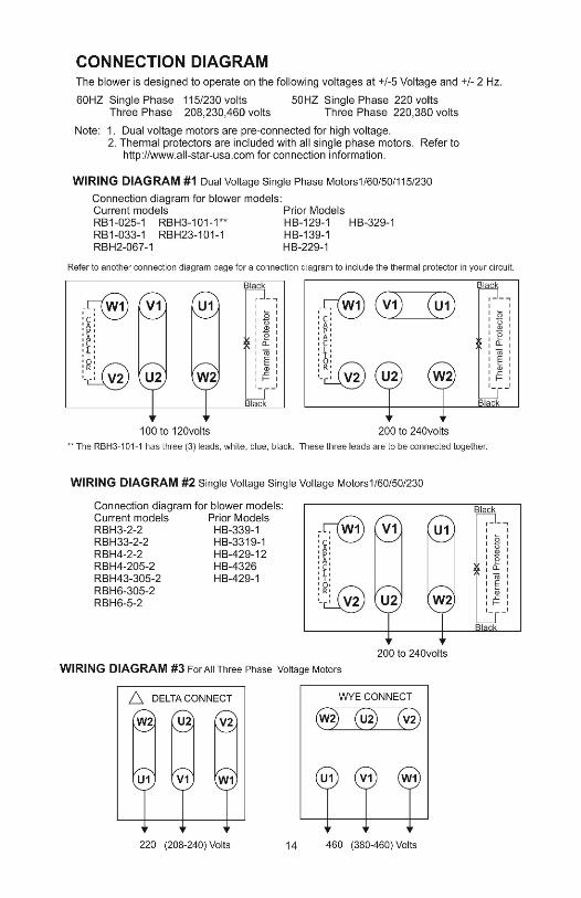
The system voltage and frequency must be the same as statedon the blower nameplate. +/-5% voltage and +/- 2% frequencyvariations are permitted without affecting the blower performance.The incoming electrical power should be connectedaccording to the wiring diagram located in this brochure or inthe conduit box. The protective earth connections should beconnected to the terminal.
The rated motor current and operating temperatures are based on a 40 Deg C ambient.
Select motor circuit breakers to match the rated motor fullload and starting currents, which typically are 600-650%higher than full current. Due to the high inertia of the blower’simpeller, starting time can extend to 5-9 seconds. As a result“slow blow” fuses should be considered.
All-Star blower motors are suitable for operation on VFDs asstandard. Shielded power leads are recommended to controlhigh requency currents and voltage harmonics caused by EMF(electro-magnetic interference).
When operating the blower with a VFD, the blower speed shouldnot exceed 4000 rpm. For higher speed operation, contact All-Star.
!
2.4 Commissioning
CAUTION The blower must not be operated with theIntake or outlet closed or blocked.
!
CAUTION If the blower is started without beingbolted to a mounting base, the initialstarting torque of the motor will causethe blower to move suddenly andpossibly topple over.
!
! CAUTION The intake ports must be sited so that noforeign elements are allowed to enter theblower and to be ejected through theexhaust (discharge) port. this is a hazardfor eyes and skin.
CAUTION When air is drawn in from the atmosphere,the intake port must be covered with aprotective screen to prevent foreign matterfrom being sucked into the blower, includingparts of the body and clothing.
-7-
For safe operation, the following conditions, as a minimummust be followed:
1. The blower should be assembled and operated according tothe data on the nameplate.
2. When a VFD is used, the blower motor speed must not exceed4000 rpm, unless the blower has been specifically approved tooperate at a higher speed.
3. The blower must be properly assembled, aligned and connected tothe intake and discharge piping or hose.
4. Installation elevation is taken into account when adjusting the blower’spressure or vacuum relief valves.
5. The direction of the motor rotation is correct.
6. The intake and discharge connections are corrent.
7. All fastenings, bolts and electrical connections are correct.
8. Earth and equi-potential bonding connections are proper.
9. All measures are taken to prevent contact with any movingor energized parts.
3.0 Lubrication
! DANGER
! DANGER
! WARNING After removing the blower cover some parts held withcentering fits and can suddenly separate, fall andpossibly cause injury and damage to the parts. Careneeds to be taken during disassembly to insure all
3.1 Disassembly
Blower models RB8 series and larger and all 2-stage blowers have an
parts are securely held in place.
external grease fitting for the blower end bearing. Other models do not,therefore disassembly is required to lubricate the bearings.
To lubricate the bearings, the rolling contact bearings and adjacentbearing housing should have the spent grease removed and replacedwith resh grease. About 50% of the rolling balls should be filled and notmore than 65% of the adjacent bearing housing should be filled.
Sealed bearings, should be replaced within the above conditions withnew bearings or as conditions warrant.
Lubricating these bearings, the blower needsbe at full operating temperature. REMOVE grease relief located at the6 o’clock position on the blower end cover; add grease through thegrease fitting until new grease begins to discharge from the relief, thenSTOP. Wait for approximately 30 minutes to allow the fresh grease toreach the blower temperature, then install the grease relief plug.
External Grease Fittings:
3.2Shielded and open bearings require lubrication. The frequency of greasing depends upon the application. As a guideline, in normal cleanenvironments with less than a 40 deg C ambient, bearings should berelubricated after approximately 10,000 hours of service or 2.5 years.If service conditions are dusty, dirty or include high operating
Bearing Types
temperatures, bearings should be lubricated more frequently.
Grease Type Mobil Hi-TemperaturePolyrex EP23.3
-8-
The bearings in All-Star blowers are filled with this lubricant, suitable forservice from -30 to + 350 Deg F. Detailed information is available at
http://www.mobil.com/USA-English/Lubes/PDS/NAUSENGRSMOMobil_Polyrex_EP_2.aspx?Print=yes
If possible different manufacturers grease should not be mixed. Checkyour local supplier for a compatible grease.
Before any work is performed on the blower, equipment and especially when removing covers on moving parts, the motor is to be disconnected from electrical power.
Do not connect electrical power supply until the blowerand other equipment are completely re-assembled.
!
WARNING
WARNING
!
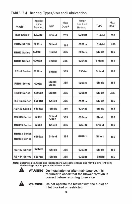
TABLE 3.4 Bearing Types,Sizes and Lubricantion
Model
Impeller
Side
BearingType Deg F
MotorFan End
BearingType Deg F
RB1 Series
RBH2 Series
RBH3 Series
RBH4 Series
RBH6 Series
RBH33 Series
RBH43 Series
RBH63 Series
6202zz Shield 285 6201zz Shield 285
6203zz Shield 6202zz Shield 385
6204z Shield 385 6204zz Shield 385
6205zz Shield 385 6204zz Shield 385
6304zz Shield 385 6204zz Shield 385
6205z Shield 385 6204zz Shield 385
6208zShield 385 6209zz Shield 385Open
6206z Shield 385 6207zz Shield 385
6206zz Shield 385 6304zz Shield 385
6206zz Shield 385 6207zz Shield 385
6309zz Shield 385 6208zz Shield 385
6203zz Shield 385 6202zz Shield 385
6207zz Shield 385 6207zz Shield 385
6207zz Shield 385 6209zz Shield 385
Note: Bearing sizes, types and lubricant are subject to change and may be different fromthe bearings in your particular blower model.
-9-
RBH8 Series
RBH9 Series
RBH23 Series
RBH63 Series
RBH83 Series
RBH84 Series
RBH64 Series
MaxMax
On installation or after maintenance, it isrequired to check that the blower rotation iscorrect before returning to service.
Do not operate the blower with the outlet orinlet blocked or restricted.
385
Open
! DANGER
4 MAINTENANCE
! DANGER
! DANGER
4.1 Cleaning
! WARNING
!
-10-
Covers which prevent contact with rotating partsare not to be opened during operation.
Before any work is performaned on theblower, equipment and especially whenremoving covers on moving parts, themotor needs to be disconnected from theelectrical power supply.
Do not connect the electrical power supplyuntil the blower and other equipment havebeen completely re-assembled.
The surface of the blower should be clean and free from dust orother contaminants. Surface dust can be blown off with a lowpressure air hose periodically to prevent a build-up of material.
When required by the operating conditions, dismantle the coverfrom the blower by removing the screws or nuts on the cover. Donot lose the screws or nuts because they are required for re-assembly.Remove and clean the cover. Clean the impeller and the internalportion of the blower with low pressure air after covering the rollingcontact bearing and the bearing grease housing. Be careful not toblower dirt or contaminants into the bearing grease. If dirt does enterthe lubricant, wash out the contaminated bearing grease, clean thebearing and replenish the bearing with fresh grease.
After removing the blower cover screws or nuts,some parts held with centering fits can suddenlyseparate, fall and possibly cause injury and damage other parts. Care needs to be takenduring re-assembly to insure no parts remain inthe blower and are securely held in place.
Covers which prevent contact with rotating parts are not to be opened during operation.
DANGER
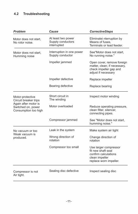
4.2 Troubleshooting
Motor does not start,No rotor noise.
Motor does not start,Humming noise
Motor-protectiveCircuit breaker tripsAgain after motor isSwitched on, powerConsumption too high
No vacuum or tooWeak vacuum isproduced.
Compressor is notAir tight.
At least two powerSupply conductorsinterrupted
Interruption in one powerSupply conductor
Impeller jammed
Impeller defective
Bearing defective
Short circuit inThe winding
Motor overloaded
Compressor jammed
Leak in the system
Wrong direction ofrotation
Compressor too small
Sealing disc defective
Problem Cause CorrectiveSteps
Eliminatei nterruption byMeans of fuses,Terminals or lead feeder.
See"Motor does not start,No running noise."
Open cover, remove foreignmatter, clean; if necessary,check impeller gap andadjust if necessary
Replace impeller
Replace bearing
Inspect motor winding
Reduce operating pressure,clean filter, silencer,connecting pipes.
See "Motor does not start,humming noise."
Make system air tight
Change direction ofrotation
Use larger compressorfit new shaft sealconfirm calculationsclean impellerreplace worn impeller.
Inspect sealing disc
-11-

-12-
5.0 SingleStageSampleAssembly
SIN
GLE
STA
GE
MO
DEL
June 2
013
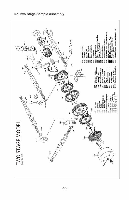
5.1 Two Stage Sample Assembly
-13-
TWO
STA
GE
MO
DEL
Septe
mber
2007
14
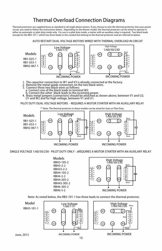
Thermal Overload Connection Diagrams
ModelsRB1-025-1RB1-033-1RBH2-067-1
1. The capacitor connection to W1 and V2 is already connected at the factory.2. Remove the metal spade connectors on the two black wires.3. Connect these two black wires as follows: a. Connect one of the black leads to terminal W2. b. Connect the other black leads to the incoming power.4. Brass metal jumpers (connectors) should be attached as shown above, between V1 and U2; U1 and W2 and for high voltage, between V1 and U1.
Low Voltage1/60/115
W1 V1 U1
V2 U2 W2
CAPA
CITO
R
THERM
AL PR
OTEC
TOR
INCOMING POWER
High Voltage1/60/50/230
W1 V1 U1
V2 U2 W2
CAPA
CITO
R
INCOMING POWER
Blue
RB1-025-1RB1-033-1RBH2-067-1
Low Voltage1/60/115
W1 V1 U1
V2 U2 W2
CAPA
CITO
R
THERM
AL PR
OTEC
TOR
INCOMING POWER
High Voltage
1/60/50/230
W1 V1 U1
V2 U2 W2
CAPA
CITO
R
THERM
AL PR
OTEC
TOR
INCOMING POWER
Black
BlackBlack
Black
AUTO RESTART DUAL VOLTAGE MOTORS WIRED WITH THERMAL OVERLOAD IN CIRCUIT
** Note: The thermal protector in these models can be wired for Auto or Pilot Duty.
White
Black
THERM
AL PR
OTEC
TOR
Blue
Black
X
Whi
te
ModelRBH3-101-1
June, 2013
Models High Voltage1/60/50/230
W1 V1 U1
V2 U2 W2
CAPA
CITO
R
THERM
AL PR
OTEC
TOR
INCOMING POWER
Black
BlackRBH3-105-2RBH3-2-2RBH33-2-2RBH4-105-2RBH4-2-2RBH4-205-2RBH43-305-2RBH6-305-2RBH6-5-2
SINGLE VOLTAGE 1/60/50/230 - PILOT DUTY ONLY - zREQUIRES A MOTOR STARTER WITH AN AUXILARY RELAY
Low Voltage1/60/115
W1 V1 U1
V2 U2 W2
CAPA
CITO
R
THERM
AL PR
OTEC
TOR
INCOMING POWER
High Voltage1/60/50/230
W1 V1 U1
V2 U2 W2
CAPA
CITO
R
THERM
AL PR
OTEC
TOR
INCOMING POWER
Black
BlackBlack
Black
Models
PILOT DUTY DUAL VOLTAGE MOTORS - REQUIRES A MOTOR STARTER WITH AN AUXILLARY RELAY
Thermal protectors are supplied loose as standard in all single phase motors. If you choose to wire the thermal protector into your powercircuit, you need to follow the instructions below. Depending on the blower model, the thermal protector can be wired to operate in either an automatic or pilot duty mode only. For use in a pilot duty mode, a starter with an auxiliary relay is required. Two black leads(except for the RB3-101-1 which has three leads) in the conduit box belong to the thermal protector and are referred to below.
Note: As noted below, the RB3-101-1 has three leads to connect the thermal protector.
15
For more detailed information, visit http://www.all-star-usa.com
All-Star Products IncSales Office & National Warehouse
2095 Exeter Rd Ste 80-324 Memphis TN 38138Tel 800-431-8258 Tel 901-755-9613 Fax 901-758-0816
All Star blowers are high quality engineered and manufactured blowers. They
Are designed to meet international standards and have received approvals andRecognition from the following agencies.
Warranty
All Star Products warrants all of its products against defects in material andto a maximum of eighteen (18) months from the date of shipment, which ever occursfirst. Purchaser is responsible for providing adequate and approved storage duringthe18 month period. Not withstanding the foregoing, any equipment or componentsof the products not of All StarsProducts own manufacture and/or specified by the
Purchaser, is sold under only such warranty as the maker thereof extends to All StarProducts and All Star Products is able to enforce, but such items are not warrantedby All Star Products in anyway. All Star Products is not responsible for productfailures caused by the purchaser or their custome rmisapplying the product, operatingthe product beyond the published ratings and values, misuse, field alterations andchanges, lack of proper maintenance or improper storage, neglect or accidents arealso excluded from this Limited Warranty. This Limited Warranty is effective, provided
(1)The purchaser immediately notifies All Star Products in writing of the allegeddefect after it becomes known to the purchaser and (2) no alterations, repairs orservices have been performed by the purchaser or third parties on the product,
This Warranty is in lieu of all other expressed or implied warranties, including any warranty of merchantability or fitness for any purpose.
The warranty does not cover misuse or misapplication, abuse, neglect or othercauses of failure beyond the manufacture's control. Do not disassemble or try torepair the blower/pump or any component. Any attempt to repair or correct a problem
by the customer or their agent will void the warranty. A disassembled unit will not be
considered as a warranted failure under any circumstances.
This warranty is voided unless an air filter has been installed and a correctly set pressureor valcuum relief valve has been installed.
ISO9001
RoHSCompliantCE
Registered and approved by one or more of these standards agency


![Hemoglobin Tetramer [Hb(O 2 )] [Hb]P O 2 K 2 = [Hb(O 2 )] [Hb]P O 2 K 3 = [Hb(O 2 )] [Hb]P O 2 K 4 = [Hb(O 2 )] [Hb]P O 2 K 1 = = 4.88 = 15.4 = 6.49 =](https://static.cupdf.com/doc/110x72/56649d5f5503460f94a3fa6a/hemoglobin-tetramer-hbo-2-hbp-o-2-k-2-hbo-2-hbp-o-2-k-3-hbo.jpg)