(IJCSIS) International Journal of Computer Science and Information Security, Vol. 11, No. 11, 2013
On the Information Hiding Technique Using Least
Significant Bits Steganography
Samir El-Seoud
Faculty of Informatics and Computer Science,
The British University in Egypt,
Cairo, Egypt
Islam Taj-Eddin
Faculty of Informatics and Computer Science,
The British University in Egypt,
Cairo, Egypt
Abstract—Steganography is the art and science of hiding data or
the practice of concealing a message, image, or file within another
message, image, or file. Steganography is often combined with
cryptography so that even if the message is discovered it cannot
be read. It is mainly used to maintain private data and/or secure
confidential data from misused through unauthorized person. In
contemporary terms, Steganography has evolved into a digital
strategy of hiding a file in some form of multimedia, such as an
image, an audio file or even a video file. This paper presents a
simple Steganography method for encoding extra information in
an image by making small modifications to its pixels. The
proposed method focuses on one particular popular technique,
Least Significant Bit (LSB) Embedding. The paper uses the
(LSB) to embed a message into an image with 24-bit (i.e. 3 bytes)
color pixels. The paper uses the (LSB) of every pixel’s bytes. The
paper show that using three bits from every pixel is robust and
the amount of change in the image will be minimal and
indiscernible to the human eye. For more protection to the
message bits a Stego-Key has been used to permute the message
bits before embedding it. A software tool that employ
steganography to hide data inside of other files (encoding) as well
as software to detect such hidden files (decoding) has been
developed and presented.
Key Words—Steganography, Hidden-Data, Embedding-Stego-
Medium, Cover-Medium, Data, Stego-Key, Stego-Image, Least
Significant Bit (LSB), 24-bit color pixel, Histogram Error (HE),
Peak Signal Noise Ratio (PSNR), Mean Square Error (MSE).
I. INTRODUCTION
One of the most important properties of digital
information is its easiness in producing and distributing
unlimited number of its copies (i.e. copies of text, audio and
video data) regardless of the protection of the intellectual
and production rights. That requires innovative ways of
embedding copyright information and serial numbers in those
copies.
Nowadays, the need for private and personal computer communication for sharing confidential information
between two parties has increased.
One such technique to solve the above mentioned
problems is Steganography [11][3]. It is the art of hiding
private information in public information used or sent on
public domain or communication from an unwanted party.
These private information need to be undetectable and/or
irremovable, especially for the audio and video data cases.
The art of hiding messages is an ancient one. Steganography (literally meaning covered writing) is a form of
security through obscurity. For example, a message might
be hidden within an image. One method to achieve that is by
changing the least significant bits to be the message bits. The
term steganography was introduced at the 15th century.
Historically, steganography was used for long time
ago. Messages were hidden (i.e. tattooed) on the scalp of
slaves. One famous example being Herodotus who in his
histories tells how Histiaeus shaved the head of his most
trusted slave and tattooed it with a message which disappeared
once the hair grew back again. Invisible ink has been for quite
some time. Microdots and microfilm technology used after the advance of the photography science and technology.
Steganography hides the private message but not the fact
that two parties are communicating. The process involves
placing a hidden message in a transport medium (i.e. the
carrier). The secret message is embedded in the carrier to form
the steganography medium. Steganography is generally
implemented by replacing bits of data, in regular computer
files, with bits of different, invisible information. Those
computer files could be graphics, sound, text or HTML. The
hidden information can be plain text, cipher text, or images.
In paper [2], the authors suggested an embedding
algorithm, using two least significant bits that minimize the
difference between the old value of the pixel in the cover and
the new value of the pixel in the stego-image in order to
minimize the distortion made to the cover file. Experimental
results of the modified method show that PSNR is greater than
the conventional method of LSBs replacement.
A distinguish between stegnography and cryptography
should be emphasized. Steganography is the science and art
of hiding information from a third party.
Cryptography is the science and art of making data
unreadable by a third party. Cryptography got more attention
from both academia and industry than steganography.
34 http://sites.google.com/site/ijcsis/ ISSN 1947-5500
(IJCSIS) International Journal of Computer Science and Information Security, Vol. 11, No. 11, 2013
Nowadays, steganography is becoming increasingly important
for both military and commercial communities [9].
II. STEGANALYSIS
Steganalysis is the science and art of detecting and
breaking steganography. Examining the color palette is one
method of the steganalysis to discover the presence of hidden
message in an image. Generally, there will be a unique binary
encoding of each individual color. If the image contains
hidden data, however, many colors in the palette will have duplicate binary encodings. If the analysis of the color
palette of a given image yields many duplicates, we might
conclude with high confidence of the presence of hidden
information.
Steganalysts have a tough job to do, because of the vast
amount of public files with different varieties (i.e. audio,
photo, video and text) they have to cover. Different varieties
require different techniques to be considered.
Steganalysis and cryptanalysis techniques can be classified in a much similar way, depending upon the known
prior information:
Steganography-only attack: Steganography medium is
available and nothing else.
Known-carrier attack: Carrier and steganography media
are both available.
Known-message attack: Hidden message is known.
Chosen-steganography attack: Steganography medium
as well as used steganography algorithm are available.
Chosen-message attack: A known message and steganography algorithm are used to create
steganography media for future analysis.
Known-steganography attack: Carrier and
steganography medium, as well as the
steganography algorithm, are available.
In [1] the author urges the steganalysis investigation of the
three least significant bits.
Until recently, information hiding techniques received very
much less attention from the research community and from
industry than cryptography, but this has changed rapidly. The
search of a safe and secret manner of communication is very
important nowadays, not only for military purposes, but also
for commercial goal related to the market strategy as well
as the copyright rights.
Steganography hides the covert message but not the fact
that two parties are communicating with each other. The
steganography process generally involves placing a hidden message in some transport medium, called the carrier. The
secret message is embedded in the carrier to form the
steganography medium. The use of a steganography key may
be employed for encryption of the hidden message and/or for
randomization in the steganography scheme.
III. HOW DOES IT WORK?
Without any loss of generality, the paper will use the
following equation to support us with a general undurstanding
of the steganographic process:
cover_medium + hidden_data + stego_key = stego_medium.
The cover_medium is the file to be used to hide the
hidden_data. A stego_key could be used if an encryption
scheme (i.e. private/public key cryptography) will be mixed
with the steganography process. The resultant file is the
stego_medium, which will be the same type of file as the
cover_medium. In this paper, we will refer to the
cover_image and stego_image, because the focus is on the
image files.
Classification of stenography techniques based on the cover
modifications applied in the embedding process is as follows:
A. Least significant bit (LSB) method This approach [19][6][5][4][14][12] is very simple. In this
method the least significant bits of some or all of the bytes inside an image is replaced with a bits of the secret
message. The least significant bit (LSB) substitution and
masking & filtering techniques are well known
techniques to data hiding in images. LSB is a simple
approach for embedding information in an image.
Replacement of LSBs in digital images is an extremely simple
form of information hiding.
B. Transform domain techniques This approach [7][10] embeds secret information in the
frequency domain of the signal. Transform domain methods hide messages in significant areas of the cover image which
make them more robust to attacks such as: compression,
cropping, and some image processing, compared to LSB
approach.
C. Statistical methods This approach [8] encodes information by changing
several statistical properties of a cover and uses a
hypothesis testing in the extraction process. The above process
is achieved by modifying the cover in such a way that some
statistical characteristics change significantly i.e. if "1" is
transmitted then cover is changed otherwise it is left as such.
D. Distortion techniques In this technique [13][18][17][16] the knowledge of
original cover in the decoding process is essential at the
receiver side. Receiver measures the differences with the
original cover in order to reconstruct the sequence of
modification applied by sender.
35 http://sites.google.com/site/ijcsis/ ISSN 1947-5500
(IJCSIS) International Journal of Computer Science and Information Security, Vol. 11, No. 11, 2013
Pixel 1= 10010101 00001101 11001001
Pixel 2= 10010110 00001111 11001010
Pixel 3= 10011111 00010000 11001011
Pixel 1= 10010100 00001101 11001000
Pixel 2= 10010110 00001111 11001010
Pixel 3= 10011110 00010000 11001011
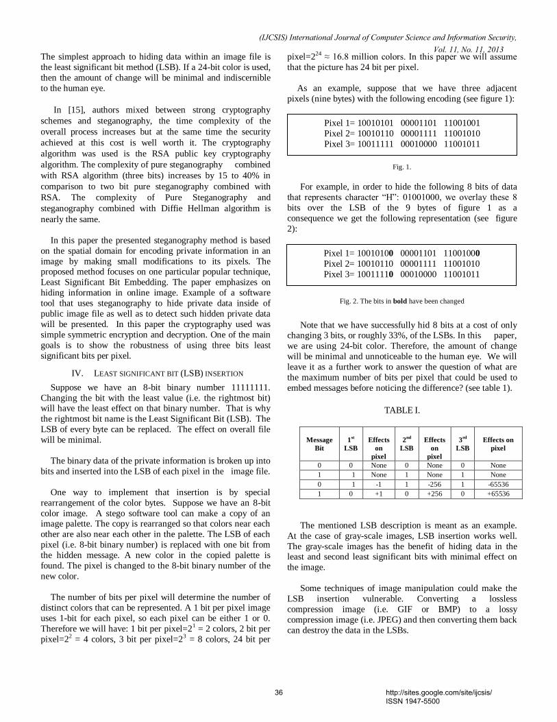
The simplest approach to hiding data within an image file is
the least significant bit method (LSB). If a 24-bit color is used,
then the amount of change will be minimal and indiscernible
to the human eye.
In [15], authors mixed between strong cryptography
schemes and steganography, the time complexity of the
overall process increases but at the same time the security
achieved at this cost is well worth it. The cryptography
algorithm was used is the RSA public key cryptography
algorithm. The complexity of pure steganography combined
with RSA algorithm (three bits) increases by 15 to 40% in
comparison to two bit pure steganography combined with
RSA. The complexity of Pure Steganography and
steganography combined with Diffie Hellman algorithm is
nearly the same.
In this paper the presented steganography method is based
on the spatial domain for encoding private information in an
image by making small modifications to its pixels. The proposed method focuses on one particular popular technique,
Least Significant Bit Embedding. The paper emphasizes on
hiding information in online image. Example of a software
tool that uses steganography to hide private data inside of
public image file as well as to detect such hidden private data
will be presented. In this paper the cryptography used was
simple symmetric encryption and decryption. One of the main
goals is to show the robustness of using three bits least
significant bits per pixel.
IV. LEAST SIGNIFICANT BIT (LSB) INSERTION
Suppose we have an 8-bit binary number 11111111.
Changing the bit with the least value (i.e. the rightmost bit) will have the least effect on that binary number. That is why
the rightmost bit name is the Least Significant Bit (LSB). The
LSB of every byte can be replaced. The effect on overall file
will be minimal.
The binary data of the private information is broken up into
bits and inserted into the LSB of each pixel in the image file.
One way to implement that insertion is by special
rearrangement of the color bytes. Suppose we have an 8-bit
color image. A stego software tool can make a copy of an image palette. The copy is rearranged so that colors near each
other are also near each other in the palette. The LSB of each
pixel (i.e. 8-bit binary number) is replaced with one bit from
the hidden message. A new color in the copied palette is
found. The pixel is changed to the 8-bit binary number of the
new color.
The number of bits per pixel will determine the number of
distinct colors that can be represented. A 1 bit per pixel image
uses 1-bit for each pixel, so each pixel can be either 1 or 0.
Therefore we will have: 1 bit per pixel=21 = 2 colors, 2 bit per
pixel=22 = 4 colors, 3 bit per pixel=23 = 8 colors, 24 bit per
pixel=224 ≈ 16.8 million colors. In this paper we will assume
that the picture has 24 bit per pixel.
As an example, suppose that we have three adjacent
pixels (nine bytes) with the following encoding (see figure 1):
Fig. 1.
For example, in order to hide the following 8 bits of data
that represents character “H”: 01001000, we overlay these 8
bits over the LSB of the 9 bytes of figure 1 as a
consequence we get the following representation (see figure
2):
Fig. 2. The bits in bold have been changed
Note that we have successfully hid 8 bits at a cost of only changing 3 bits, or roughly 33%, of the LSBs. In this paper,
we are using 24-bit color. Therefore, the amount of change
will be minimal and unnoticeable to the human eye. We will
leave it as a further work to answer the question of what are
the maximum number of bits per pixel that could be used to
embed messages before noticing the difference? (see table 1).
TABLE I.
The mentioned LSB description is meant as an example.
At the case of gray-scale images, LSB insertion works well.
The gray-scale images has the benefit of hiding data in the least and second least significant bits with minimal effect on
the image.
Some techniques of image manipulation could make the
LSB insertion vulnerable. Converting a lossless
compression image (i.e. GIF or BMP) to a lossy
compression image (i.e. JPEG) and then converting them back
can destroy the data in the LSBs.
Message
Bit
1st
LSB
Effects
on
pixel
2nd
LSB
Effects
on
pixel
3rd
LSB
Effects on
pixel
0 0 None 0 None 0 None
1 1 None 1 None 1 None
0 1 -1 1 -256 1 -65536
1 0 +1 0 +256 0 +65536
36 http://sites.google.com/site/ijcsis/ ISSN 1947-5500
(IJCSIS) International Journal of Computer Science and Information Security, Vol. 11, No. 11, 2013
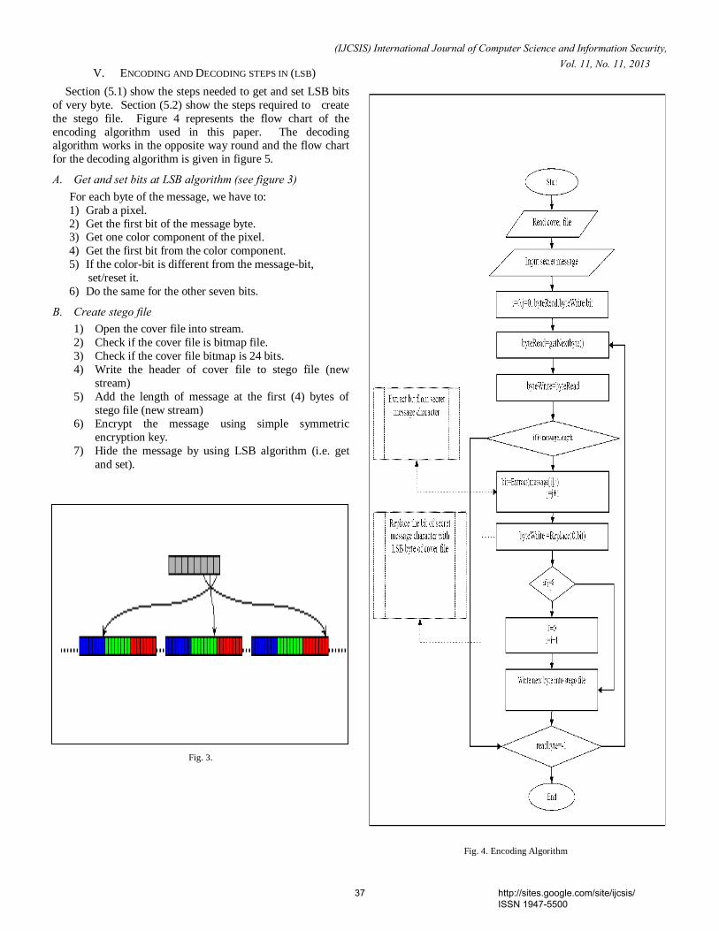
V. ENCODING AND DECODING STEPS IN (LSB)
Section (5.1) show the steps needed to get and set LSB bits
of very byte. Section (5.2) show the steps required to create
the stego file. Figure 4 represents the flow chart of the
encoding algorithm used in this paper. The decoding algorithm works in the opposite way round and the flow chart
for the decoding algorithm is given in figure 5.
A. Get and set bits at LSB algorithm (see figure 3) For each byte of the message, we have to:
1) Grab a pixel.
2) Get the first bit of the message byte. 3) Get one color component of the pixel.
4) Get the first bit from the color component.
5) If the color-bit is different from the message-bit,
set/reset it.
6) Do the same for the other seven bits.
B. Create stego file 1) Open the cover file into stream.
2) Check if the cover file is bitmap file.
3) Check if the cover file bitmap is 24 bits.
4) Write the header of cover file to stego file (new
stream)
5) Add the length of message at the first (4) bytes of
stego file (new stream)
6) Encrypt the message using simple symmetric
encryption key.
7) Hide the message by using LSB algorithm (i.e. get
and set).
Fig. 3.
Fig. 4. Encoding Algorithm
37 http://sites.google.com/site/ijcsis/ ISSN 1947-5500
(IJCSIS) International Journal of Computer Science and Information Security, Vol. 11, No. 11, 2013
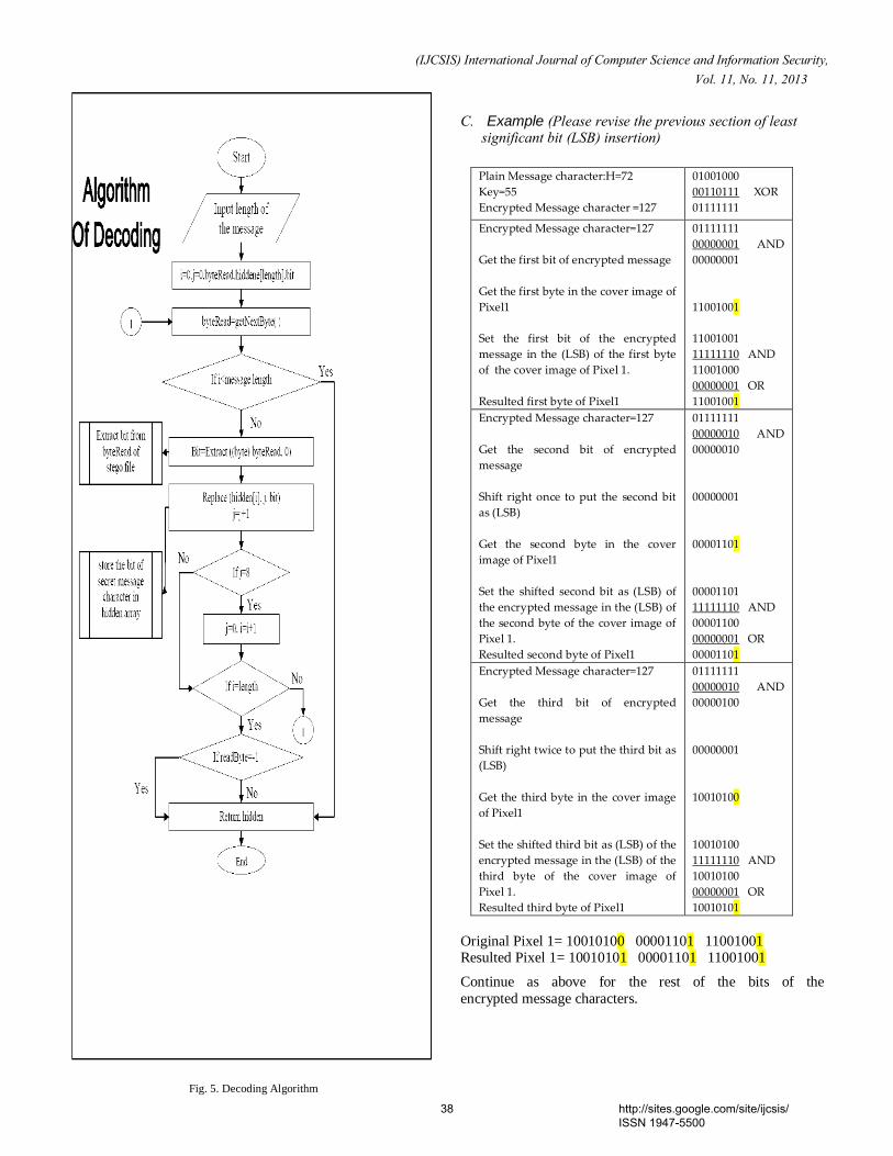
C. Example (Please revise the previous section of least significant bit (LSB) insertion)
Plain Message character:H=72
Key=55
Encrypted Message character =127
01001000
00110111 XOR
01111111
Encrypted Message character=127
Get the first bit of encrypted message
Get the first byte in the cover image of
Pixel1
Set the first bit of the encrypted
message in the (LSB) of the first byte
of the cover image of Pixel 1.
Resulted first byte of Pixel1
01111111
00000001 AND
00000001
11001001
11001001
11111110 AND
11001000
00000001 OR
11001001
Encrypted Message character=127
Get the second bit of encrypted
message
Shift right once to put the second bit
as (LSB)
Get the second byte in the cover
image of Pixel1
Set the shifted second bit as (LSB) of
the encrypted message in the (LSB) of
the second byte of the cover image of
Pixel 1.
Resulted second byte of Pixel1
01111111
00000010 AND
00000010
00000001
00001101
00001101
11111110 AND
00001100
00000001 OR
00001101
Encrypted Message character=127
Get the third bit of encrypted
message
Shift right twice to put the third bit as
(LSB)
Get the third byte in the cover image
of Pixel1
Set the shifted third bit as (LSB) of the
encrypted message in the (LSB) of the
third byte of the cover image of
Pixel 1.
Resulted third byte of Pixel1
01111111
00000010 AND
00000100
00000001
10010100
10010100
11111110 AND
10010100
00000001 OR
10010101
Original Pixel 1= 10010100 00001101 11001001 Resulted Pixel 1= 10010101 00001101 11001001
Continue as above for the rest of the bits of the
encrypted message characters.
Fig. 5. Decoding Algorithm
38 http://sites.google.com/site/ijcsis/ ISSN 1947-5500
(IJCSIS) International Journal of Computer Science and Information Security, Vol. 11, No. 11, 2013
The C#-functions for getting and setting single bit are simple:
private static bool GetBit(byte b, byte position)
{return ((b & (byte)(1 << position)) != 0);}
private static byte SetBit(byte b, byte position,
bool newBitValue)
{byte mask = (byte)(1 << position); if(newBitValue){
return (byte)(b | mask);}
else
{return (byte)(b & ~mask);}
}
A proposed Pseudo-code for hiding messages:
A proposed Pseudo-code for extracting hidden messages:
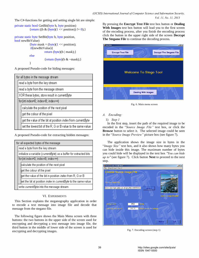
VI. EXPERIMENTS
This Section explains the steganography application in order
to encode a text message into image file and decode that
message from the stegano file.
The following figure shows the Main Menu screen with three
buttons: the two buttons in the upper side of the screen used for
encrypting and decrypting a text message into image file, the
third button in the middle of lower side of the screen is used for
encrypting and decrypting images.
By pressing the Encrypt Text File text box button or Dealing
With Images text box button will lead you to the first screen
of the encoding process, after you finish the encoding process
click the button in the upper right side of the screen Decrypt
The Stegano File to continue the decoding process.
A. Encoding: 1) Step 1
In the first step, insert the path of the required image to be
encoded in the “Source Image File” text box, or click the
Browse button to select it. The selected image could be seen
in the “Source Image Preview” picture box (see figure 7).
The application shows the image size in bytes in the
“Image Size” text box, and it also shows how many bytes you
can hide inside this image. The maximum number of bytes you could hide will be displayed in the text box "You can hide up to" (see figure 7). Click button Next to proceed to the next
step.
Fig. 6. Main menu screen
Fig. 7. Encoding screen (step 1)
39 http://sites.google.com/site/ijcsis/ ISSN 1947-5500
(IJCSIS) International Journal of Computer Science and Information Security, Vol. 11, No. 11, 2013
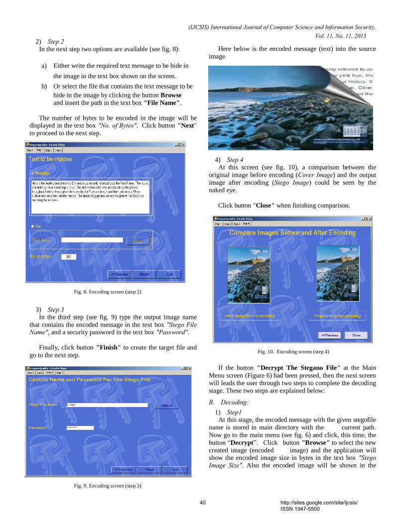
2) Step 2 In the next step two options are available (see fig. 8):
a) Either write the required text message to be hide in
the image in the text box shown on the screen.
b) Or select the file that contains the text message to be
hide in the image by clicking the button Browse
and insert the path in the text box "File Name".
The number of bytes to be encoded in the image will be displayed in the text box "No. of Bytes". Click button "Next"
to proceed to the next step.
3) Step 3 In the third step (see fig. 9) type the output image name
that contains the encoded message in the text box "Stego File Name", and a security password in the text box "Password".
Finally, click button "Finish" to create the target file and
go to the next step.
Here below is the encoded message (text) into the source
image
4) Step 4 At this screen (see fig. 10), a comparison between the
original image before encoding (Cover Image) and the output
image after encoding (Stego Image) could be seen by the
naked eye.
Click button "Close" when finishing comparison.
If the button "Decrypt The Stegano File" at the Main
Menu screen (Figure 6) had been pressed, then the next screen
will leads the user through two steps to complete the decoding
stage. These two steps are explained below:
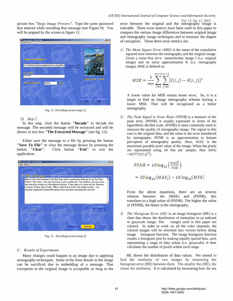
B. Decoding: 1) Step1
At this stage, the encoded message with the given stegofile
name is stored in main directory with the current path.
Now go to the main menu (see fig. 6) and click, this time, the
button “Decrypt”. Click button "Browse" to select the new
created image (encoded image) and the application will show the encoded image size in bytes in the text box "Stego Image Size". Also the encoded image will be shown in the
Fig. 8. Encoding screen (step 2)
Fig. 9. Encoding screen (step 3)
Fig. 10. Encoding screen (step 4)
40 http://sites.google.com/site/ijcsis/ ISSN 1947-5500
(IJCSIS) International Journal of Computer Science and Information Security, Vol. 11, No. 11, 2013
picture box "Stego Image Preview". Type the same password
that entered while encoding that message (see Figure 9). You
will be popped by the screen in figure 11.
2) Step 2 In this step, click the button "Decode" to decode the
message. The encoded message will be extracted and will be
shown in text box "The Extracted Message" (see fig. 12).
Either save the message to a file by pressing the button
"Save To File" or clear the message shown by pressing the
button "Clear". Click button "Exit" to exit the
application.
C. Results of Experiments Many changes could happen to an image due to applying
stenography techniques. Some of the finer details in the image
can be sacrificed due to embedding of a message. That
corruption to the original image is acceptable as long as the
error between the original and the stenography image is
tolerable. Three error metrics have been used in this paper to
compare the various image differences between original image
and stenography image techniques and to measure the degree
of corruption. These three error metrics are:
1) The Mean Square Error (MSE) is the mean of the cumulative
squared error between the stenography and the original image.
Given a noise-free m×n monochrome image I (i.e. original image) and its noisy approximation K (i.e. stenography
image), MSE is defined as:
A lower value for MSE means lesser error. So, it is a
target to find an image stenography scheme having a
lower MSE. That will be recognized as a better stenography.
2) The Peak Signal to Noise Ratio (PSNR) is a measure of the
peak error. (PSNR) is usually expressed in terms of the logarithmic decibel scale. (PSNR) is most commonly used to
measure the quality of stenography image. The signal in this case is the original data, and the noise is the error introduced
by stenography. PSNR is an approximation to human perception of stenography quality. Here, MAXI is the
maximum possible pixel value of the image. When the pixels are represented using 24 bits per sample, then MAXI
=16777215 (224
).
From the above equations, there are an inverse
relation between the (MSE) and (PSNR), this
translates to a high value of (PSNR). The higher the value
of (PSNR), the better is the stenography. 3) The Histogram Error (HE) is an image histogram (HE) is a
chart that shows the distribution of intensities in an indexed or grayscale image. The images used in this paper are
colored. In order to work on all the color channels, the colored images will be stretched into vectors before doing
image histogram function. The image histogram function creates a histogram plot by making equally spaced bins, each
representing a range of data values (i.e. grayscale). It then calculates the number of pixels within each range.
HE shows the distribution of data values. We intend to find the similarity of two images by measuring the
histogram error (HE) between them. The smaller the (HE), the
closer the similarity. It is calculated by measuring how far are
Fig. 11. Decoding screen (step 1)
Fig. 12. Decoding screen (step 2)
41 http://sites.google.com/site/ijcsis/ ISSN 1947-5500
(IJCSIS) International Journal of Computer Science and Information Security, Vol. 11, No. 11, 2013
the differences between two normalized histograms that
belong to two different images, from each other. That could
happen by subtracting the two normalized histograms vectors
from each other and then squaring the resulted vector. There
exist an inverse relationship between the value of (HE) and
how close the two normalized histograms are to each others.
It implies that the smaller the (HE) the closer to each other are
the images. Let the two histogram images Im1 (i.e. original
image) and Im2 (stenography image) be denoted by Im1 and Im2, respectively, and assuming the two images having the
same m×n size. Calculate the Normalized Histograms hn1 and
hn2 of Image 1 and Image 2, then finally calculate (HE) as the
following:
,
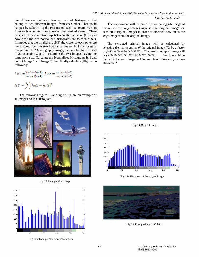
The following figure 13 and figure 13a are an example of
an image and it’s Histogram:
The experiment will be done by comparing (the original
image vs. the stegoimage) against (the original image vs.
corrupted original image) in order to discover how far is the
stegoimage from the original image.
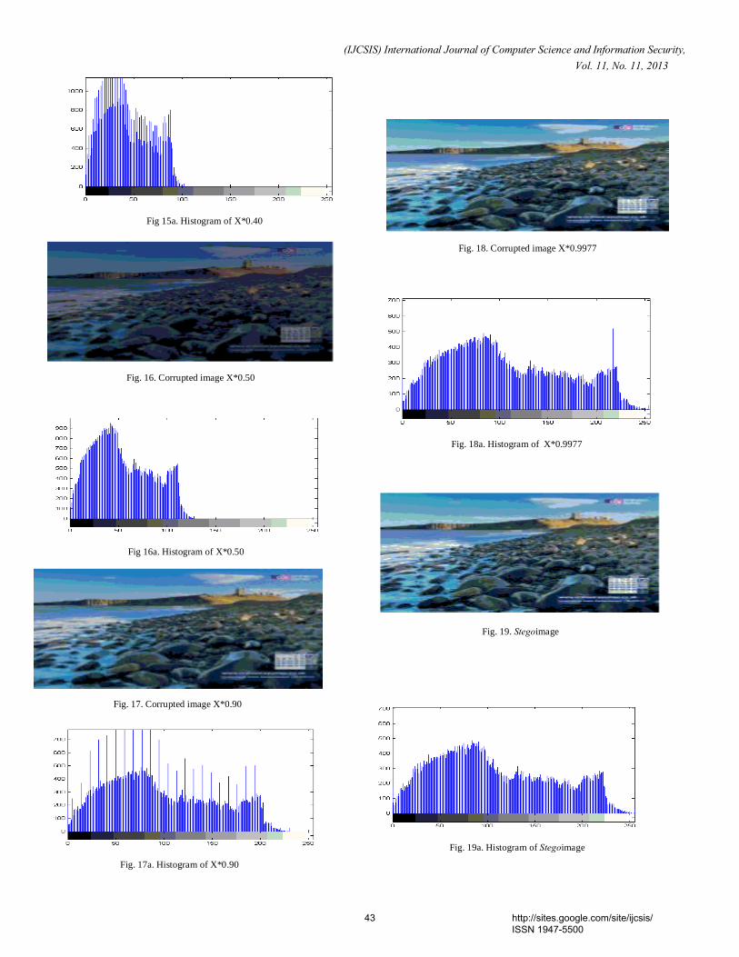
The corrupted original image will be calculated by
adjusting the matrix entries of the original image (X) by a factor
of (0.40, 0.50, 0.90 & 0.9977) . The results corrupted image will
be (X*0.10, X*0.50, X*0.90 & X*0.9977). See figure 14 to
figure 19 for each image and its associated histogram, and see
also table 2.
Fig. 13. Example of an image
Fig. 14a. Histogram of the original image
Fig. 13a. Example of an image' histogram
Fig. 15. Corrupted image X*0.40
Fig. 14. Original Image
42 http://sites.google.com/site/ijcsis/ ISSN 1947-5500
(IJCSIS) International Journal of Computer Science and Information Security, Vol. 11, No. 11, 2013
Fig 15a. Histogram of X*0.40
Fig. 16. Corrupted image X*0.50
Fig. 17a. Histogram of X*0.90
Fig. 19. Stegoimage
Fig. 18a. Histogram of X*0.9977
Fig. 18. Corrupted image X*0.9977
Fig 16a. Histogram of X*0.50
Fig. 17. Corrupted image X*0.90
Fig. 19a. Histogram of Stegoimage
43 http://sites.google.com/site/ijcsis/ ISSN 1947-5500
(IJCSIS) International Journal of Computer Science and Information Security, Vol. 11, No. 11, 2013
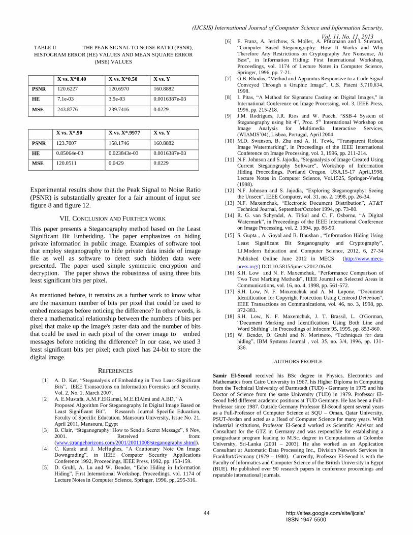
Experimental results show that the Peak Signal to Noise Ratio
(PSNR) is substantially greater for a fair amount of input see
figure 8 and figure 12.
VII. CONCLUSION AND FURTHER WORK
This paper presents a Steganography method based on the Least Significant Bit Embedding. The paper emphasizes on hiding
private information in public image. Examples of software tool that employ steganography to hide private data inside of image
file as well as software to detect such hidden data were presented. The paper used simple symmetric encryption and
decryption. The paper shows the robustness of using three bits least significant bits per pixel.
As mentioned before, it remains as a further work to know what
are the maximum number of bits per pixel that could be used to
embed messages before noticing the difference? In other words, is
there a mathematical relationship between the numbers of bits per
pixel that make up the image's raster data and the number of bits
that could be used in each pixel of the cover image to embed
messages before noticing the difference? In our case, we used 3
least significant bits per pixel; each pixel has 24-bit to store the
digital image.
REFERENCES
[1] A. D. Ker, “Steganalysis of Embedding in Two Least-Significant
Bits”, IEEE Transactions on Information Forensics and Security,
Vol. 2, No. 1, March 2007.
[2] A. E.Mustafa, A.M.F.ElGamal, M.E.ElAlmi and A.BD, “A
Proposed Algorithm For Steganography In Digital Image Based on
Least Significant Bit”. Research Journal Specific Education,
Faculty of Specific Education, Mansoura University, Issue No. 21,
April 2011, Mansoura, Egypt
[3] B. Clair, “Steganography: How to Send a Secret Message”, 8 Nov,
2001. Retreived from:
(www.strangehorizons.com/2001/20011008/steganography.shtml).
[4] C. Kurak and J. McHughes, “A Cautionary Note On Image
Downgrading”, in IEEE Computer Security Applications
Conference 1992, Proceedings, IEEE Press, 1992, pp. 153-159.
[5] D. Gruhl, A. Lu and W. Bender, “Echo Hiding in Information
Hiding”, First International Workshop, Proceedings, vol. 1174 of
Lecture Notes in Computer Science, Springer, 1996, pp. 295-316.
[6] E. Franz, A. Jerichow, S. Moller, A. Pfitzmann and I. Stierand,
“Computer Based Steganography: How It Works and Why
Therefore Any Restrictions on Cryptography Are Nonsense, At
Best”, in Information Hiding: First International Workshop,
Proceedings, vol. 1174 of Lecture Notes in Computer Science,
Springer, 1996, pp. 7-21.
[7] G.B. Rhodas, “Method and Apparatus Responsive to a Code Signal
Conveyed Through a Graphic Image”, U.S. Patent 5,710,834,
1998.
[8] I. Pitas, “A Method for Signature Casting on Digital Images," in
International Conference on Image Processing, vol. 3, IEEE Press,
1996, pp. 215-218.
[9] J.M. Rodrigues, J.R. Rios and W. Puech, “SSB-4 System of
Steganography using bit 4”, Proc. 5th
International Workshop on
Image Analysis for Multimedia Interactive Services,
(WIAMIS’04), Lisboa, Portugal, April 2004.
[10] M.D. Swanson, B. Zhu and A. H. Tewk, “Transparent Robust
Image Watermarking", in Proceedings of the IEEE International
Conference on Image Processing, vol. 3, 1996, pp. 211-214.
[11] N.F. Johnson and S. Jajodia, "Steganalysis of Image Created Using
Current Steganography Software", Workshop of Information
Hiding Proceedings, Portland Oregon, USA,15-17 April,1998.
Lecture Notes in Computer Science, Vol.1525, Springer-Verlag
(1998).
[12] N.F. Johnson and S. Jajodia, “Exploring Steganography: Seeing
the Unseen", IEEE Computer, vol. 31, no. 2, 1998, pp. 26-34.
[13] N.F. Maxemchuk, “Electronic Document Distribution”, AT&T
Technical Journal, September/October 1994, pp. 73-80.
[14] R. G. van Schyndel, A. Tirkel and C. F. Osborne, “A Digital
Watermark”, in Proceedings of the IEEE International Conference
on Image Processing, vol. 2, 1994, pp. 86-90.
[15] S. Gupta , A. Goyal and B. Bhushan , “Information Hiding Using
Least Significant Bit Steganography and Cryptography”,
I.J.Modern Education and Computer Science, 2012, 6, 27-34
Published Online June 2012 in MECS (http://www.mecs-
press.org/) DOI:10.5815/ijmecs.2012.06.04
[16] S.H. Low and N. F. Maxemchuk, “Performance Comparison of
Two Text Marking Methods”, IEEE Journal on Selected Areas in
Communications, vol. 16, no. 4, 1998, pp. 561-572.
[17] S.H. Low, N. F. Maxemchuk and A. M. Lapone, “Document
Identification for Copyright Protection Using Centroid Detection”,
IEEE Transactions on Communications, vol. 46, no. 3, 1998, pp.
372-383.
[18] S.H. Low, N. F. Maxemchuk, J. T. Brassil, L. O'Gorman,
“Document Marking and Identifications Using Both Line and
Word Shifting", in Proceedings of Infocom'95, 1995, pp. 853-860.
[19] W. Bender, D. Gruhl and N. Morimoto, “Techniques for data
hiding”, IBM Systems Journal , vol. 35, no. 3/4, 1996, pp. 131-
336.
AUTHORS PROFILE
Samir El-Seoud received his BSc degree in Physics, Electronics and
Mathematics from Cairo University in 1967, his Higher Diploma in Computing
from the Technical University of Darmstadt (TUD) - Germany in 1975 and his
Doctor of Science from the same University (TUD) in 1979. Professor El-
Seoud held different academic positions at TUD Germany. He has been a Full-
Professor since 1987. Outside Germany Professor El-Seoud spent several years
as a Full-Professor of Computer Science at SQU – Oman, Qatar University,
PSUT-Jordan and acted as a Head of Computer Science for many years. With
industrial institutions, Professor El-Seoud worked as Scientific Advisor and
Consultant for the GTZ in Germany and was responsible for establishing a
postgraduate program leading to M.Sc. degree in Computations at Colombo
University, Sri-Lanka (2001 – 2003). He also worked as an Application
Consultant at Automatic Data Processing Inc., Division Network Services in
Frankfurt/Germany (1979 – 1980). Currently, Professor El-Seoud is with the
Faculty of Informatics and Computer Science of the British University in Egypt
(BUE). He published over 90 research papers in conference proceedings and
reputable international journals.
TABLE II THE PEAK SIGNAL TO NOISE RATIO (PSNR),
HISTOGRAM ERROR (HE) VALUES AND MEAN SQUARE ERROR
(MSE) VALUES
X vs. X*0.40 X vs. X*0.50 X vs. Y
PSNR 120.6227 120.6970 160.8882
HE 7.1e-03 3.9e-03 0.0016387e-03
MSE 243.8776 239.7416 0.0229
X vs. X*.90 X vs. X*.9977 X vs. Y
PSNR 123.7007 158.1746 160.8882
HE 0.85064e-03 0.023843e-03 0.0016387e-03
MSE 120.0511 0.0429 0.0229
44 http://sites.google.com/site/ijcsis/ ISSN 1947-5500
(IJCSIS) International Journal of Computer Science and Information Security, Vol. 11, No. 11, 2013
Islam Taj-Eddin received his Ph.D., M.Phil. M.S. all in computer science
from the City University of New York in fall 2007, spring 2007 and spring
2000 respectively. His BSc degree in Computer Science, from King Saud
University in Spring 1997. Dr. Taj-Eddin held different academic positions at
USA and Egypt. He was an Adjunct Assistant Lecturer at Lehman College of
the City University of New York, and Fordham College at Rose Hill of
Fordham University. He was a Lecturer at Alexandria Higher Institute of
Engineering & Technology at Alexandria city of Egypt. Currently he is a
Lecturer at the British University in Egypt. He has published almost a dozen
refereed research papers related to Algorithms, E-learning, Web-Based
Education, Software Engineering, Technology for special needs users. He is
interested also in the subject of quality assurance in research and education.
45 http://sites.google.com/site/ijcsis/ ISSN 1947-5500