Relion® 630 series
Motor Protection and ControlREM630Product Guide

Contents
1. Description...........................................................3
2. Application...........................................................3
3. Preconfigurations.................................................5
4. Protection functions.............................................9
5. Control................................................................11
6. Measurement.....................................................11
7. Disturbance recorder..........................................11
8. Event log.............................................................11
9. Disturbance report.............................................12
10. Circuit-breaker monitoring................................12
11. Trip-circuit supervision......................................12
12. Self-supervision.................................................12
13. Fuse failure supervision.....................................12
14. Current circuit supervision................................13
15. Access control...................................................13
16. Inputs and outputs............................................13
17. Communication.................................................15
18. Technical data...................................................16
19. Front panel user interface.................................55
20. Mounting methods............................................55
21. Selection and ordering data..............................57
22. Accessories.......................................................61
24. Tools..................................................................62
25. Supported ABB solutions..................................64
26. Terminal diagrams.............................................65
27. References........................................................69
28. Functions, codes and symbols.........................69
29. Document revision history.................................73
Disclaimer
The information in this document is subject to change without notice and should not be construed as a commitment by ABB Oy. ABB Oy assumesno responsibility for any errors that may appear in this document.
© Copyright 2011 ABB Oy.
All rights reserved.
Trademarks
ABB and Relion are registered trademarks of ABB Group. All other brand or product names mentioned in this document may be trademarks orregistered trademarks of their respective holders.
Motor Protection and Control 1MRS756977 DREM630Product version: 1.1 Issued: 2011-05-18
2 ABB
1. Description
REM630 is a comprehensive motormanagement IED for protection, control,measuring and supervision of medium andlarge synchronous and asynchronous motorsin medium voltage industrial power systems.
REM630 is a member of ABB’s Relion®
product family and a part of its 630 seriescharacterized by functional scalability andflexible configurability. REM630 also featuresnecessary control functions required for themanagement of industrial motor feeder bays.
The supported communication protocolsincluding IEC 61850 offer seamlessconnectivity to industrial automation systems.
2. Application
REM630 provides main protection forsynchronous and asynchronous motors and
the associated drives. The motor managementIED is intended for circuit-breaker andcontactor controlled medium sized and largesynchronous and asynchronous motors in avariety of drive applications, such as motordrives for pumps, fans, compressors, mills,crushers, etc.
The pre-defined configuration developed forREM630 can be used as such or easilycustomized or extended with add-onfunctions, by means of which the motormanagement IED can be fine-tuned to exactlysatisfy the specific requirements of yourpresent application.
Motor Protection and Control 1MRS756977 DREM630Product version: 1.1 Issued: 2011-05-18
Revision: D
ABB 3
GUID-193D49D0-CEA0-46BD-9C08-525B147AE0F0 V2 EN
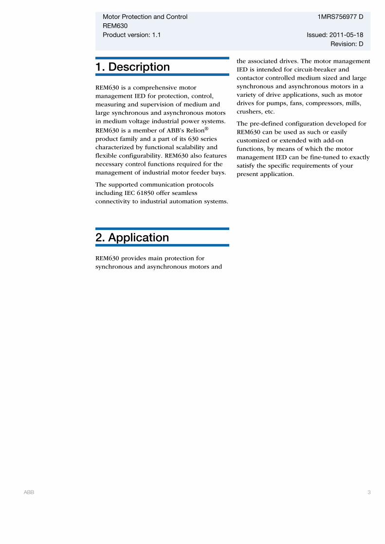
Figure 1. RET630 and REM630 IEDs applied for the incoming feeder and primary switchgearin a single busbar arrangement. The RET630 with preconfiguration A is used forprotection and control of the power transformer, the REM630 IEDs withpreconfiguration A are used for the circuit-breaker and contactor operated motorfeeders. The motor start-up signal from each REM630 is connected to the “Restartinhibit” inputs of the other REM630s. Hence while one motor is starting-up, thestarting of the other motors is inhibited.
Motor Protection and Control 1MRS756977 DREM630Product version: 1.1 Issued: 2011-05-18
4 ABB
3. Preconfigurations
The 630 series IEDs are offered with optionalfactory-made preconfigurations for variousapplications. The preconfigurationscontribute to faster commissioning and lessengineering of the IED. Thepreconfigurations include defaultfunctionality typically needed for a specificapplication. Each preconfiguration isadaptable using the Protection and ControlIED Manager PCM600. By adapting thepreconfiguration the IED can be configuredto suit the particular application.
The adaptation of the preconfiguration mayinclude adding or removing of protection,control and other functions according to thespecific application, changing of the defaultparameter settings, configuration of thedefault alarms and event recorder settingsincluding the texts shown in the HMI,
configuration of the LEDs and functionbuttons, and adaptation of the default single-line diagram.
In addition, the adaptation of thepreconfiguration always includescommunication engineering to configure thecommunication according to the functionalityof the IED. The communication engineeringis done using the communicationconfiguration function of PCM600.
If none of the offeredpreconfigurations fulfill theneeds of the intended area ofapplication, 630 series IEDscan also be ordered withoutany preconfiguration. In thiscase the IED needs to beconfigured from the groundup.
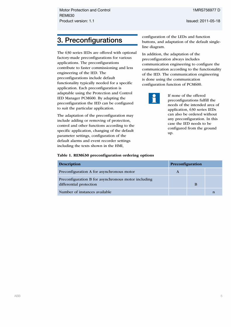
Table 1. REM630 preconfiguration ordering options
Description Preconfiguration
Preconfiguration A for asynchronous motor A
Preconfiguration B for asynchronous motor includingdifferential protection B
Number of instances available n
Motor Protection and Control 1MRS756977 DREM630Product version: 1.1 Issued: 2011-05-18
ABB 5

Table 2. Functions used in preconfigurations. Column 'n' shows the total number ofavailable function instances regardless of the preconfiguration selected.
Functionality A B n
Protection
Three-phase non-directional overcurrent, low stage 1 1 1
Three-phase non-directional overcurrent, instantaneous stage 1 1 1
Non-directional earth-fault protection, low stage 1 1 1
Non-directional earth-fault, high stage 1 1 1
Non-directional earth-fault, instantaneous stage - - 1
Directional earth-fault, low stage - - 1
Directional earth-fault, high stage - - 1
Rotor earth-fault protection1) - - 1
Negative-sequence overcurrent protection for motors 2 2 2
Phase reversal protection 1 1 1
Three-phase thermal overload for motors 1 1 1
Motor startup supervision 1 1 1
Motor load jam protection 1 1 1
Emergency start 1 1 1
Loss of load supervision 1 1 1
High-impedance or flux-balance-based differential protectionfor machines
- - 1
Stabilized differential protection for motors1) - 1 1
Three-phase overvoltage - - 2
Three-phase undervoltage - - 2
Positive-sequence overvoltage 1 1 2
Positive-sequence undervoltage 1 1 2
Negative-sequence overvoltage 1 1 2
Residual overvoltage - - 3
Frequency gradient1) - - 6
Overfrequency1) - - 3
Underfrequency1) - - 3
Three-phase underexcitation protection1) - - 2
Motor Protection and Control 1MRS756977 DREM630Product version: 1.1 Issued: 2011-05-18
6 ABB

Table 2. Functions used in preconfigurations. Column 'n' shows the total number ofavailable function instances regardless of the preconfiguration selected., continued
Functionality A B n
Directional overpower protection1) - - 3
Circuit breaker failure 1 1 2
Tripping logic 1 1 2
Multipurpose analog protection - - 16
Control
Bay control 1 1 1
Interlocking interface 2 2 10
Circuit breaker/disconnector control 2 2 10
Circuit breaker 1 1 2
Disconnector 1 1 8
Local/remote switch interface - - 1
Generic process I/O
Single point control (8 signals) - - 5
Double point indication - - 15
Single point indication - - 64
Generic measured value - - 15
Logic rotating switch for function selection and LHMIpresentation
- - 10
Selector mini switch - - 10
Pulse counter for energy metering - - 4
Event counter - - 1
Supervision and monitoring
Circuit-breaker condition monitoring 1 1 1
Fuse failure supervision 1 1 1
Current circuit supervision 1 1 1
Trip circuit supervision 3 3 3
Energy monitoring 1 1 1
Station battery supervision - - 1
Measured value limit supervision - - 40
Measurement
Motor Protection and Control 1MRS756977 DREM630Product version: 1.1 Issued: 2011-05-18
ABB 7
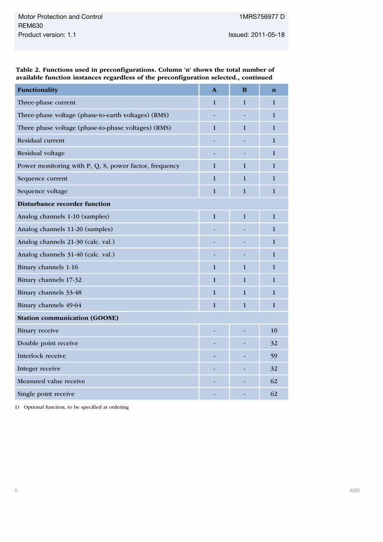
Table 2. Functions used in preconfigurations. Column 'n' shows the total number ofavailable function instances regardless of the preconfiguration selected., continued
Functionality A B n
Three-phase current 1 1 1
Three-phase voltage (phase-to-earth voltages) (RMS) - - 1
Three phase voltage (phase-to-phase voltages) (RMS) 1 1 1
Residual current - - 1
Residual voltage - - 1
Power monitoring with P, Q, S, power factor, frequency 1 1 1
Sequence current 1 1 1
Sequence voltage 1 1 1
Disturbance recorder function
Analog channels 1-10 (samples) 1 1 1
Analog channels 11-20 (samples) - - 1
Analog channels 21-30 (calc. val.) - - 1
Analog channels 31-40 (calc. val.) - - 1
Binary channels 1-16 1 1 1
Binary channels 17-32 1 1 1
Binary channels 33-48 1 1 1
Binary channels 49-64 1 1 1
Station communication (GOOSE)
Binary receive - - 10
Double point receive - - 32
Interlock receive - - 59
Integer receive - - 32
Measured value receive - - 62
Single point receive - - 62
1) Optional function, to be specified at ordering
Motor Protection and Control 1MRS756977 DREM630Product version: 1.1 Issued: 2011-05-18
8 ABB
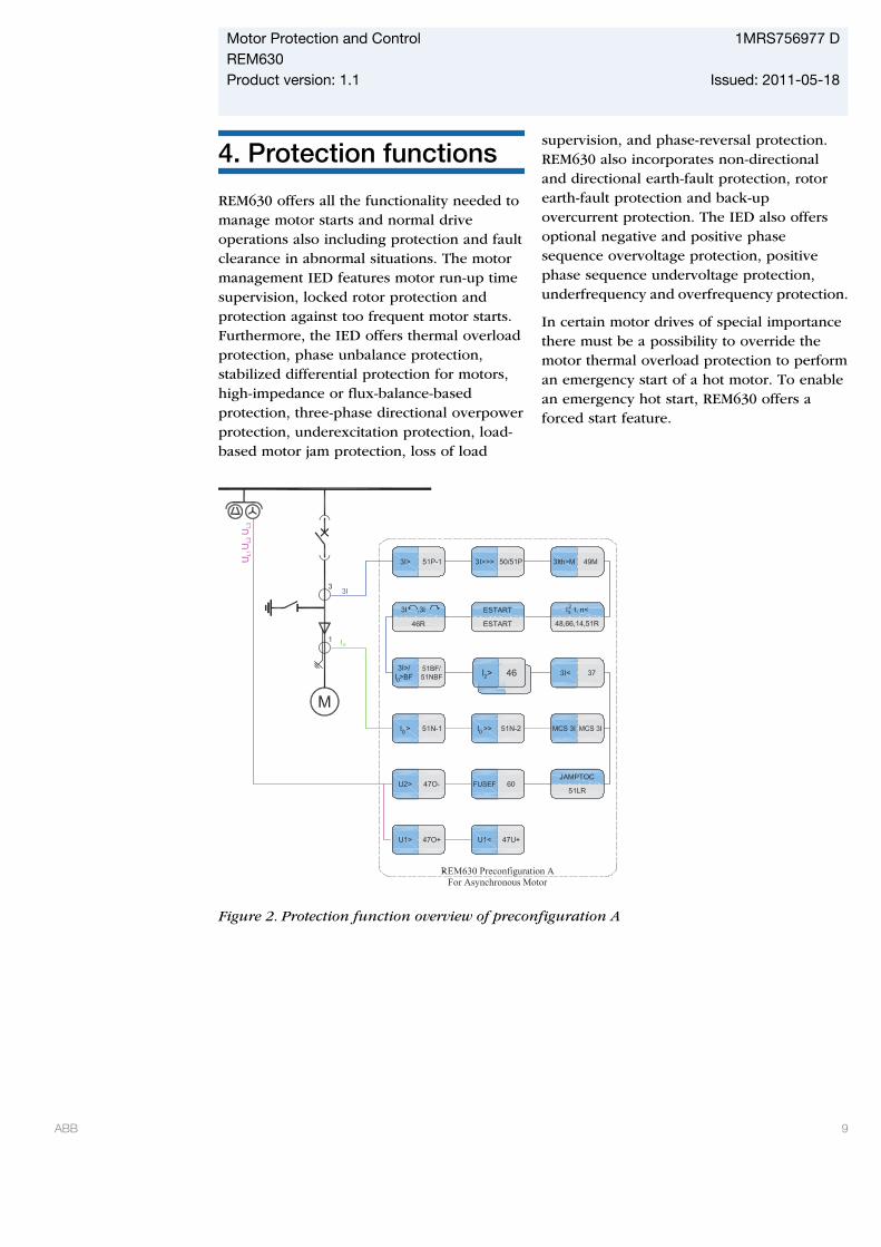
4. Protection functions
REM630 offers all the functionality needed tomanage motor starts and normal driveoperations also including protection and faultclearance in abnormal situations. The motormanagement IED features motor run-up timesupervision, locked rotor protection andprotection against too frequent motor starts.Furthermore, the IED offers thermal overloadprotection, phase unbalance protection,stabilized differential protection for motors,high-impedance or flux-balance-basedprotection, three-phase directional overpowerprotection, underexcitation protection, load-based motor jam protection, loss of load
supervision, and phase-reversal protection.REM630 also incorporates non-directionaland directional earth-fault protection, rotorearth-fault protection and back-upovercurrent protection. The IED also offersoptional negative and positive phasesequence overvoltage protection, positivephase sequence undervoltage protection,underfrequency and overfrequency protection.
In certain motor drives of special importancethere must be a possibility to override themotor thermal overload protection to performan emergency start of a hot motor. To enablean emergency hot start, REM630 offers aforced start feature.
GUID-79E59A23-7C6B-4EF4-AEAD-D077F425C7A9 V2 EN
Figure 2. Protection function overview of preconfiguration A
Motor Protection and Control 1MRS756977 DREM630Product version: 1.1 Issued: 2011-05-18
ABB 9

GUID-24B763F7-2621-4672-B0A1-06ABD84FD12B V1 EN
Figure 3. Protection function overview of preconfiguration B
Motor Protection and Control 1MRS756977 DREM630Product version: 1.1 Issued: 2011-05-18
10 ABB

5. Control
The IED incorporates local and remotecontrol functions. The IED offers a number offreely assignable binary inputs/outputs andlogic circuits for establishing bay control andinterlocking functions for circuit breakers andmotor operated switch-disconnectors. TheIED supports both single and double busbarsubstation busbar layouts. The number ofcontrollable primary apparatuses depends onthe number of available inputs and outputs inthe selected configuration. Besidesconventional hardwired signaling alsoGOOSE messaging according to IEC61850-8-1 can be used for signal interchangebetween IEDs to obtain required interlockings.
6. Measurement
The IED continuously measures the phasecurrents, the symmetrical components of thecurrents and the residual current. The IEDalso measures phase and phase-to-phasevoltages, symmetrical components of thevoltages and the residual voltage. In addition,the IED monitors active and reactive power,power demand value over a user-selectablepre-set time frames as well as cumulativeactive and reactive energy of both directions.Line frequency, the thermal overload of theprotected object, and the phase unbalancevalue based on the ratio between thenegative sequence and positive sequencecurrent are also calculated. Cumulative andaveraging calculations utilize the non-volatilememory available in the IED. Calculatedvalues are also obtained from the protectionand condition monitoring functions of the IED.
The values measured are accessed locally viathe front-panel user interface of the IED orremotely via the communication interface ofthe IED. The values are also accessed locallyor remotely using the web-browser baseduser interface.
7. Disturbance recorder
The IED is provided with a disturbancerecorder featuring up to 40 analog and 64binary signal channels. The analog channelscan be set to record the waveform of thecurrents and voltage measured. The analogchannels can be set to trigger the recordingwhen the measured value falls below orexceeds the set values. The binary signalchannels can be set to start a recording onthe rising or the falling edge of the binarysignal. The binary channels are set to recordexternal or internal IED signals, for examplethe start or operate signals of the protectionfunctions, or external blocking or controlsignals. Binary IED signals such as aprotection start or trip signal, or an externalIED control signal over a binary input can beset to trigger the recording. In addition, thedisturbance recorder settings include pre- andpost triggering times.
The disturbance recorder can store up to 100recordings. The number of recordings mayvary depending on the length of therecording and the number of signalsincluded. The disturbance recorder controlsthe Start and Trip LEDs on the front-paneluser interface. The operation of the LEDs isfully configurable enabling activation whenone or several criteria, that is, protectionfunction starting or tripping, are fulfilled.
The recorded information is stored in a non-volatile memory and can be uploaded forsubsequent fault analysis.
8. Event log
The IED features an event log which enableslogging of event information. The event logcan be configured to log informationaccording to user pre-defined criteriaincluding IED signals. To collect sequence-of-events (SoE) information, the IEDincorporates a non-volatile memory with a
Motor Protection and Control 1MRS756977 DREM630Product version: 1.1 Issued: 2011-05-18
ABB 11
capacity of storing 1000 events withassociated time stamps and user definableevent texts. The non-volatile memory retainsits data also in case the IED temporarily losesits auxiliary supply. The event log facilitatesdetailed pre- and post-fault analyses of faultsand disturbances.
The SoE information can be accessed locallyvia the user interface on the IED front panelor remotely via the communication interfaceof the IED. The information can further beaccessed, either locally or remotely, using theweb-browser based user interface.
The logging of communication events isdetermined by the used communicationprotocol and the communication engineering.The communication events are automaticallysent to station automation and SCADAsystems once the required communicationengineering has been done.
9. Disturbance report
The disturbance report includes informationcollected during the fault situation. Thereport includes general information such asrecording time, pre-fault time and post faulttime. Further, the report includes pre-faultmagnitude, pre-fault angle, fault magnitudeand fault angle trip values. By default, thedisturbance reports are stored in a non-volatile memory. The numerical disturbancereport can be accessed via the local frontpanel user interface. A more comprehensivedisturbance report with waveforms isavailable using PCM600.
10. Circuit-breakermonitoring
The condition monitoring functions of theIED constantly monitors the performance andthe condition of the circuit breaker. The
monitoring comprises the spring chargingtime, SF6 gas pressure, the travel-time,operation counter, accumulated energycalculator, circuit-breaker life estimator andthe inactivity time of the circuit breaker.
The monitoring functions provide operationalcircuit breaker history data, which can beused for scheduling preventive circuit breakermaintenance.
11. Trip-circuitsupervision
The trip-circuit supervision continuouslymonitors the availability and operability ofthe trip circuit. It provides open-circuitmonitoring both when the circuit breaker isin its closed and in its open position. It alsodetects loss of circuit-breaker control voltage.
12. Self-supervision
The IED’s built-in self-supervision systemcontinuously monitors the state of the IEDhardware and the operation of the IEDsoftware. Any fault or malfunction detected isused for alerting the operator.
Self-supervision events are saved into aninternal event list which can be accessedlocally via the user interface on the IED frontpanel. The event list can also be accessedusing the web-browser based user interfaceor PCM600.
13. Fuse failuresupervision
The fuse failure supervision detects failuresbetween the voltage measurement circuit and
Motor Protection and Control 1MRS756977 DREM630Product version: 1.1 Issued: 2011-05-18
12 ABB
the IED. The failures are detected by thenegative-sequence based algorithm or by thedelta voltage and delta current algorithm.Upon the detection of a failure the fusefailure supervision function activates an alarmand blocks voltage-dependent protectionfunctions from unintended operation.
14. Current circuitsupervision
Current circuit supervision is used fordetecting faults in the current transformersecondary circuits. On detecting of a fault thecurrent circuit supervision function can alsoactivate an alarm LED and block certainprotection functions to avoid unintendedoperation. The current circuit supervisionfunction calculates the sum of the phasecurrents and compares the sum with themeasured single reference current from acore balance current transformer or fromanother set of phase current transformers.
15. Access control
To protect the IED from unauthorized accessand to maintain information integrity, the IEDis provided with an authentication systemincluding user management. Using the IEDUser Management tool in the Protection andControl IED Manager PCM600, an individualpassword is assigned to each user by theadministrator. Further, the user name isassociated to one or more of the fouravailable user groups: System Operator,Protection Engineer, Design Engineer andUser Administrator. The user groupassociation for each individual user enablesthe use of the IED according to the profile ofthe user group.
16. Inputs and outputs
The IED is equipped with three phase-currentinputs and two residual-current inputs forearth-fault protection. The IED alwaysincludes one residual voltage input fordirectional earth-fault protection or residualvoltage protection. Further, the IED includesthree phase-voltage inputs for overvoltage,undervoltage and directional overcurrentprotection and other voltage based protectionfunctions.
The phase-current inputs are rated 1/5 A. TheIED is equipped with two alternative residual-current inputs, that is 1/5 A or 0.1/0.5 A. The0.1/0.5 A input is normally used inapplications requiring sensitive earth-faultprotection and featuring a core-balancecurrent transformer.
The three phase-voltage inputs, for eitherphase-to-phase voltages or phase-to-earthvoltages, and the residual-voltage input coverthe rated voltages 100 V, 110 V, 115 V and120 V. The rated values of the current andvoltage inputs are selected in the IED software.
In addition, the binary input thresholds areselected by adjusting the IED’s parametersettings. The threshold voltage can be setseparately for each binary input.
There is also an optional RTD/mA modulewith 8 RTD/mA inputs and 4 mA outputs.The optional RTD/mA module facilitates themeasurement of up to eight analog signalsvia the RTD or mA inputs and provides fourmA outputs. The RTD and mA inputs can forinstance be used for temperaturemeasurement of motor bearings and statorwindings, thus extending the functionality ofthe thermal overload protection andpreventing premature aging of the motorwindings. Furthermore, the RTD and mAinputs can be used for measuring the ambientair or cooling media temperature. The RTDand mA inputs can be used for supervision ofanalog mA signals provided by externaltransducers. The RTD/mA inputs can bealternatively used also as resistance input or
Motor Protection and Control 1MRS756977 DREM630Product version: 1.1 Issued: 2011-05-18
ABB 13
as an input for voltage transducer. The RTD/mA module enables the use of themultipurpose protection functions. Theseprotection functions can be used for trippingand alarm purposes based on RTD/mAmeasuring data, or analog valuescommunicated via GOOSE messaging. ThemA outputs can be used for transferringfreely selectable measured or calculatedanalog values to devices provided with mAinput capabilities.
The enhanced scalability of the 6U variantIEDs are intended for optimized medium
voltage metal-clad switchgear applicationswhere additional binary inputs and outputsare often required.
All binary input and output contacts arefreely configurable using the signal matrix ofthe application configuration function inPCM600.
Please refer to the Input/output overviewtables, the selection and ordering data andthe terminal diagrams for more detailedinformation about the inputs and outputs.
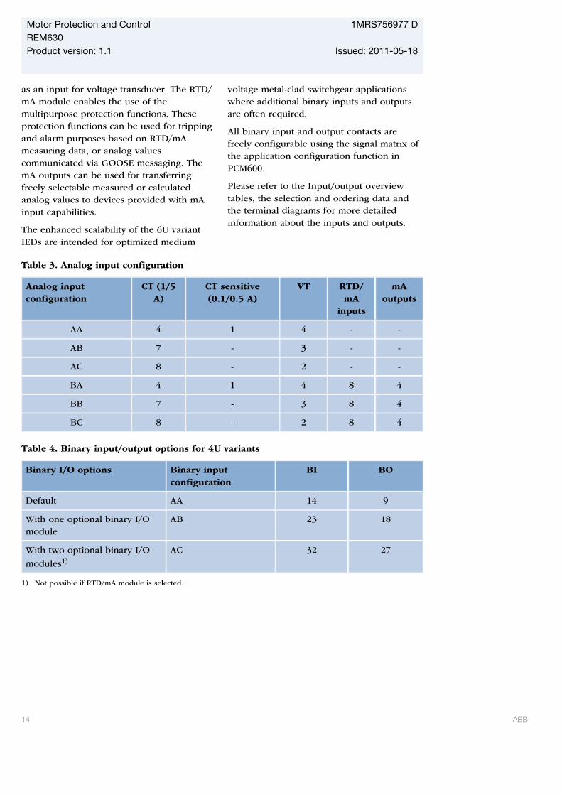
Table 3. Analog input configuration
Analog inputconfiguration
CT (1/5A)
CT sensitive(0.1/0.5 A)
VT RTD/mA
inputs
mAoutputs
AA 4 1 4 - -
AB 7 - 3 - -
AC 8 - 2 - -
BA 4 1 4 8 4
BB 7 - 3 8 4
BC 8 - 2 8 4
Table 4. Binary input/output options for 4U variants
Binary I/O options Binary inputconfiguration
BI BO
Default AA 14 9
With one optional binary I/Omodule
AB 23 18
With two optional binary I/O
modules1)
AC 32 27
1) Not possible if RTD/mA module is selected.
Motor Protection and Control 1MRS756977 DREM630Product version: 1.1 Issued: 2011-05-18
14 ABB

Table 5. Binary input/output options for 6U variants
Binary I/O options Binary inputconfiguration
BI BO
Default AA 14 9
With one optional binary I/Omodule
AB 2318
With two optional binary I/Omodules
AC 32 27
With three optional binary I/Omodules
AD 4136
With four optional binary I/O
modules1) AE 50 45
1) Not possible if RTD/mA module is selected.
17. Communication
The IED supports the IEC 61850 substationautomation standard including horizontalGOOSE communication as well as the well-established DNP3 (TCP/IP) and IEC60870-5-103 protocols. All operationalinformation and controls are availablethrough these protocols.
Seamless connectivity to industrialautomation systems is achieved with theStation Automation COM600 device using theOPC Server/Client technology. COM600works as a gateway between the DistributedControl System (DCS) and the bay level IEDsenabling sending of monitoring data andreceiving of power distribution processcontrol commands.
Disturbance files are accessed using the IEC61850 or IEC 60870-5-103 protocols.Disturbance files are also available to anyEthernet based application in the standardCOMTRADE format. The IED can send binarysignals to other IEDs (so called horizontalcommunication) using the IEC 61850-8-1GOOSE (Generic Object Oriented SubstationEvent) profile. Binary GOOSE messaging can,
for example, be employed for protection andinterlocking-based protection schemes. TheIED meets the GOOSE performancerequirements for tripping applications indistribution substations, as defined by theIEC 61850 standard. Further, the IEDsupports the sending and receiving of analogvalues using GOOSE messaging. AnalogGOOSE messaging enables fast transfer ofanalog measurement values over the stationbus, thus facilitating for example sharing ofRTD input values, such as surroundingtemperature values, to other IEDapplications. The IED interoperates withother IEC 61850 compliant IEDs, tools andsystems and simultaneously reports events tofive different clients on the IEC 61850 stationbus. For a system using DNP3 over TCP/IP,events can be sent to four different masters.For systems using IEC 60870-5-103 IED canbe connected to one master in a station buswith star-topology.
All communication connectors, except for thefront port connector, are placed on integratedcommunication modules. The IED isconnected to Ethernet-based communicationsystems via the RJ-45 connector (10/100BASE-TX) or the fibre-optic multimode LCconnector (100BASE-FX).
Motor Protection and Control 1MRS756977 DREM630Product version: 1.1 Issued: 2011-05-18
ABB 15
IEC 60870-5-103 is available from opticalserial port where it is possible to use serialglass fibre (ST connector) or serial plasticfibre (snap-in connector).
The IED supports SNTP, DNP3 and IRIG-Btime synchronization methods with a time-stamping resolution of 1 ms.
The IED supports the following timesynchronization methods with atimestamping resolution of 1 ms:
Ethernet communication based:
• SNTP (simple network time protocol)• DNP3
With special time synchronization wiring:
• IRIG-B (Inter-Range Instrumentation Group- Time Code Format B)
IEC 60870-5-103 serial communication has atime-stamping resolution of 10 ms.
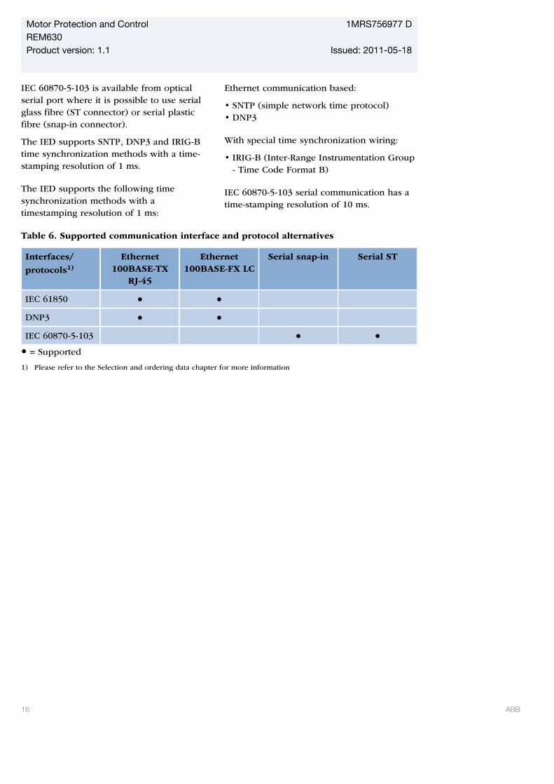
Table 6. Supported communication interface and protocol alternatives
Interfaces/
protocols1)
Ethernet100BASE-TX
RJ-45
Ethernet100BASE-FX LC
Serial snap-in Serial ST
IEC 61850
DNP3
IEC 60870-5-103 = Supported
1) Please refer to the Selection and ordering data chapter for more information
Motor Protection and Control 1MRS756977 DREM630Product version: 1.1 Issued: 2011-05-18
16 ABB
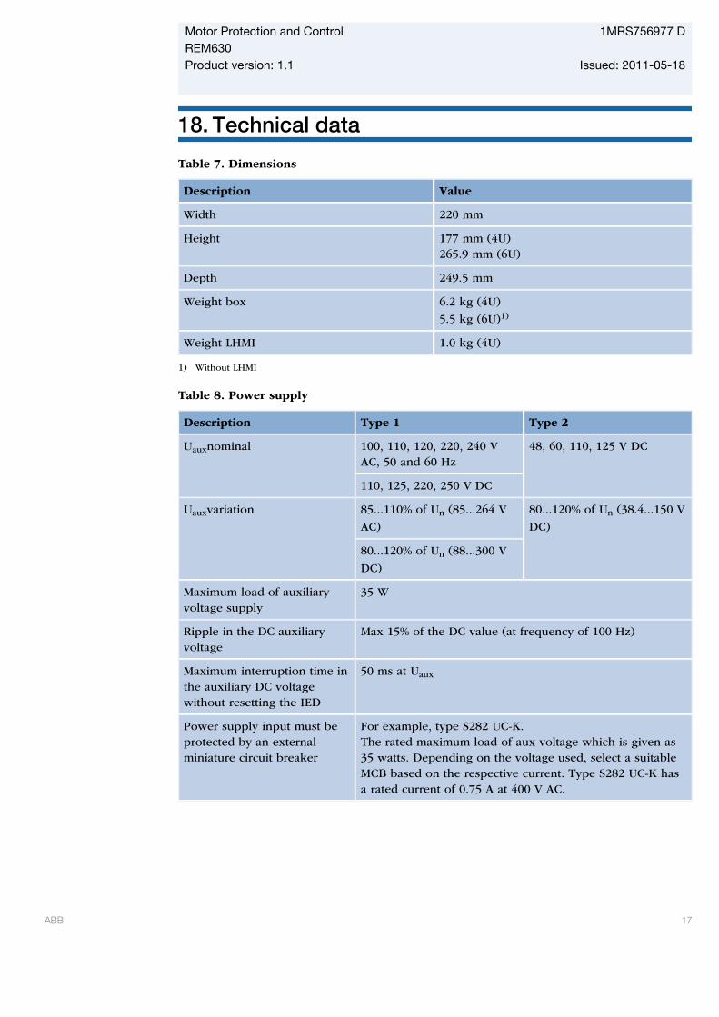
18. Technical data
Table 7. Dimensions
Description Value
Width 220 mm
Height 177 mm (4U)265.9 mm (6U)
Depth 249.5 mm
Weight box 6.2 kg (4U)
5.5 kg (6U)1)
Weight LHMI 1.0 kg (4U)
1) Without LHMI
Table 8. Power supply
Description Type 1 Type 2
Uauxnominal 100, 110, 120, 220, 240 VAC, 50 and 60 Hz
48, 60, 110, 125 V DC
110, 125, 220, 250 V DC
Uauxvariation 85...110% of Un (85...264 V
AC)
80...120% of Un (38.4...150 V
DC)
80...120% of Un (88...300 V
DC)
Maximum load of auxiliaryvoltage supply
35 W
Ripple in the DC auxiliaryvoltage
Max 15% of the DC value (at frequency of 100 Hz)
Maximum interruption time inthe auxiliary DC voltagewithout resetting the IED
50 ms at Uaux
Power supply input must beprotected by an externalminiature circuit breaker
For example, type S282 UC-K.The rated maximum load of aux voltage which is given as35 watts. Depending on the voltage used, select a suitableMCB based on the respective current. Type S282 UC-K hasa rated current of 0.75 A at 400 V AC.
Motor Protection and Control 1MRS756977 DREM630Product version: 1.1 Issued: 2011-05-18
ABB 17

Table 9. Energizing inputs
Description Value
Rated frequency 50/60 Hz
Operating range Rated frequency ± 5 Hz
Current inputs Rated current, In 0.1/0.5 A1) 1/5 A2)
Thermal withstandcapability:
• Continuously 4 A 20 A
• For 1 s 100 A 500 A
• For 10 s 25 A 100 A
Dynamic currentwithstand:
• Half-wave value 250 A 1250 A
Input impedance <100 mΩ <20 mΩ
Voltage inputs Rated voltage, Un 100 V AC/ 110 V AC/ 115 V AC/ 120 V AC
Voltage withstand:
• Continuous 425 V AC
• For 10 s 450 V AC
Burden at rated voltage <0.05 VA
1) Residual current2) Phase currents or residual current
Table 10. Binary inputs
Description Value
Operating range Maximum input voltage 300 V DC
Rated voltage 24...250 V DC
Current drain 1.6...1.8 mA
Power consumption/input <0.3 W
Threshold voltage 15...221 V DC (parametrizable in the range insteps of 1% of the rated voltage)
Threshold voltage accuracy ±3.0%
Motor Protection and Control 1MRS756977 DREM630Product version: 1.1 Issued: 2011-05-18
18 ABB
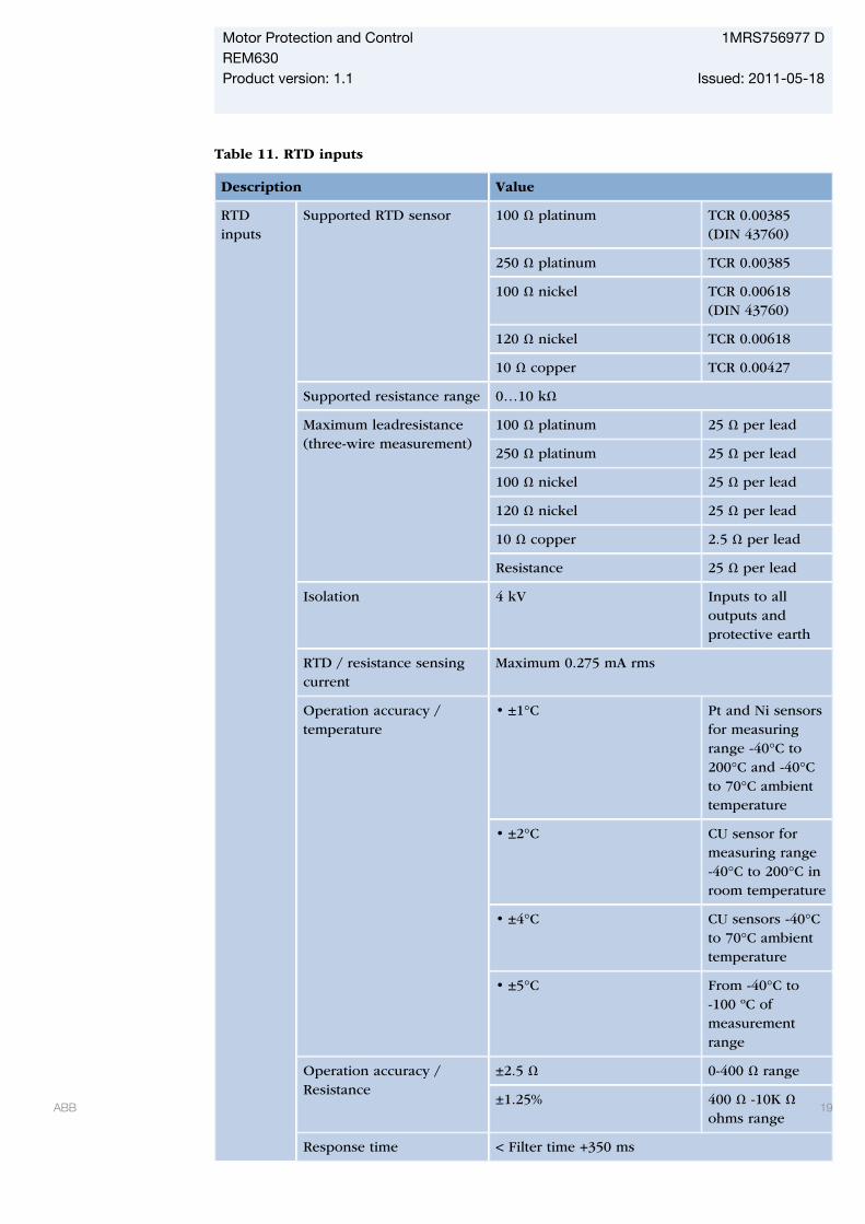
Table 11. RTD inputs
Description Value
RTDinputs
Supported RTD sensor 100 Ω platinum TCR 0.00385(DIN 43760)
250 Ω platinum TCR 0.00385
100 Ω nickel TCR 0.00618(DIN 43760)
120 Ω nickel TCR 0.00618
10 Ω copper TCR 0.00427
Supported resistance range 0…10 kΩ
Maximum leadresistance(three-wire measurement)
100 Ω platinum 25 Ω per lead
250 Ω platinum 25 Ω per lead
100 Ω nickel 25 Ω per lead
120 Ω nickel 25 Ω per lead
10 Ω copper 2.5 Ω per lead
Resistance 25 Ω per lead
Isolation 4 kV Inputs to alloutputs andprotective earth
RTD / resistance sensingcurrent
Maximum 0.275 mA rms
Operation accuracy /temperature
• ±1°C Pt and Ni sensorsfor measuringrange -40°C to200°C and -40°Cto 70°C ambienttemperature
• ±2°C CU sensor formeasuring range-40°C to 200°C inroom temperature
• ±4°C CU sensors -40°Cto 70°C ambienttemperature
• ±5°C From -40°C to-100 ºC ofmeasurementrange
Operation accuracy /Resistance
±2.5 Ω 0-400 Ω range
±1.25% 400 Ω -10K Ωohms range
Response time < Filter time +350 ms
Motor Protection and Control 1MRS756977 DREM630Product version: 1.1 Issued: 2011-05-18
ABB 19
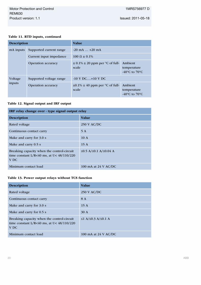
Table 11. RTD inputs, continued
Description Value
mA inputs Supported current range -20 mA … +20 mA
Current input impedance 100 Ω ± 0.1%
Operation accuracy ± 0.1% ± 20 ppm per °C of full-scale
Ambienttemperature-40°C to 70°C
Voltageinputs
Supported voltage range -10 V DC….+10 V DC
Operation accuracy ±0.1% ± 40 ppm per °C of full-scale
Ambienttemperature-40°C to 70°C
Table 12. Signal output and IRF output
IRF relay change over - type signal output relay
Description Value
Rated voltage 250 V AC/DC
Continuous contact carry 5 A
Make and carry for 3.0 s 10 A
Make and carry 0.5 s 15 A
Breaking capacity when the control-circuittime constant L/R<40 ms, at U< 48/110/220V DC
≤0.5 A/≤0.1 A/≤0.04 A
Minimum contact load 100 mA at 24 V AC/DC
Table 13. Power output relays without TCS function
Description Value
Rated voltage 250 V AC/DC
Continuous contact carry 8 A
Make and carry for 3.0 s 15 A
Make and carry for 0.5 s 30 A
Breaking capacity when the control-circuittime constant L/R<40 ms, at U< 48/110/220V DC
≤1 A/≤0.3 A/≤0.1 A
Minimum contact load 100 mA at 24 V AC/DC
Motor Protection and Control 1MRS756977 DREM630Product version: 1.1 Issued: 2011-05-18
20 ABB
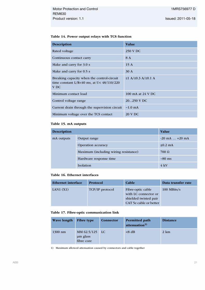
Table 14. Power output relays with TCS function
Description Value
Rated voltage 250 V DC
Continuous contact carry 8 A
Make and carry for 3.0 s 15 A
Make and carry for 0.5 s 30 A
Breaking capacity when the control-circuittime constant L/R<40 ms, at U< 48/110/220V DC
≤1 A/≤0.3 A/≤0.1 A
Minimum contact load 100 mA at 24 V DC
Control voltage range 20...250 V DC
Current drain through the supervision circuit ~1.0 mA
Minimum voltage over the TCS contact 20 V DC
Table 15. mA outputs
Description Value
mA outputs Output range -20 mA … +20 mA
Operation accuracy ±0.2 mA
Maximum (including wiring resistance) 700 Ω
Hardware response time ~80 ms
Isolation 4 kV
Table 16. Ethernet interfaces
Ethernet interface Protocol Cable Data transfer rate
LAN1 (X1) TCP/IP protocol Fibre-optic cablewith LC connector orshielded twisted pairCAT 5e cable or better
100 MBits/s
Table 17. Fibre-optic communication link
Wave length Fibre type Connector Permitted path
attenuation1)
Distance
1300 nm MM 62.5/125μm glassfibre core
LC <8 dB 2 km
1) Maximum allowed attenuation caused by connectors and cable together
Motor Protection and Control 1MRS756977 DREM630Product version: 1.1 Issued: 2011-05-18
ABB 21
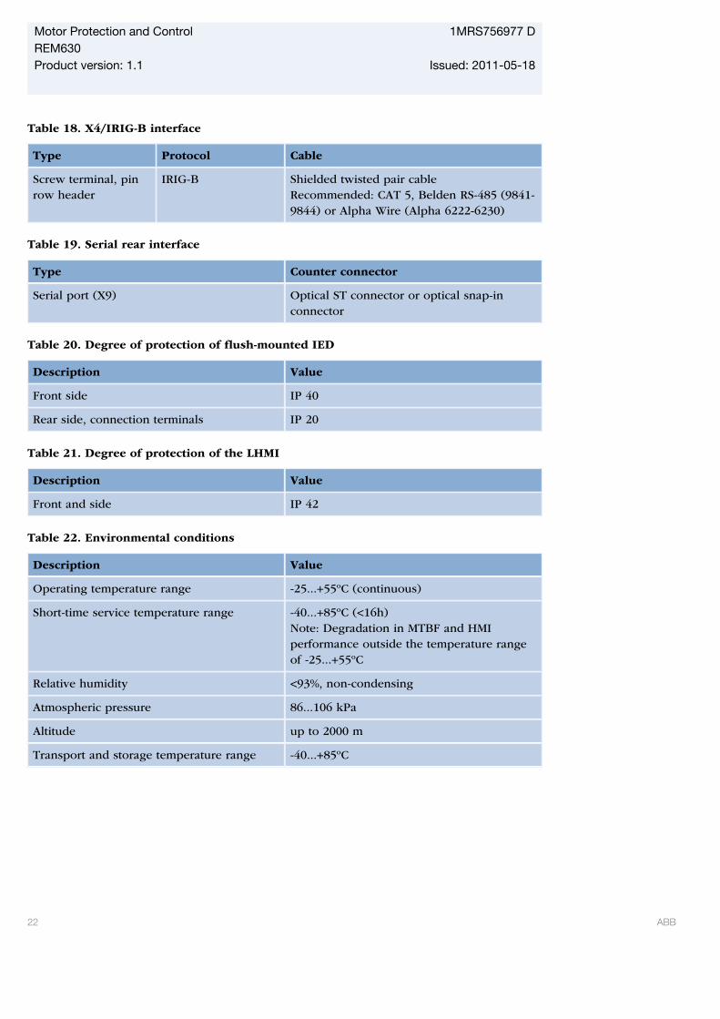
Table 18. X4/IRIG-B interface
Type Protocol Cable
Screw terminal, pinrow header
IRIG-B Shielded twisted pair cableRecommended: CAT 5, Belden RS-485 (9841-9844) or Alpha Wire (Alpha 6222-6230)
Table 19. Serial rear interface
Type Counter connector
Serial port (X9) Optical ST connector or optical snap-inconnector
Table 20. Degree of protection of flush-mounted IED
Description Value
Front side IP 40
Rear side, connection terminals IP 20
Table 21. Degree of protection of the LHMI
Description Value
Front and side IP 42
Table 22. Environmental conditions
Description Value
Operating temperature range -25...+55ºC (continuous)
Short-time service temperature range -40...+85ºC (<16h)Note: Degradation in MTBF and HMIperformance outside the temperature rangeof -25...+55ºC
Relative humidity <93%, non-condensing
Atmospheric pressure 86...106 kPa
Altitude up to 2000 m
Transport and storage temperature range -40...+85ºC
Motor Protection and Control 1MRS756977 DREM630Product version: 1.1 Issued: 2011-05-18
22 ABB
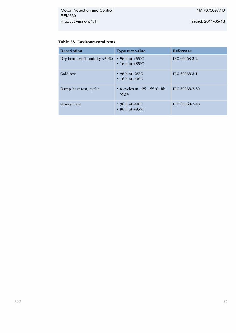
Table 23. Environmental tests
Description Type test value Reference
Dry heat test (humidity <50%) • 96 h at +55ºC• 16 h at +85ºC
IEC 60068-2-2
Cold test • 96 h at -25ºC• 16 h at -40ºC
IEC 60068-2-1
Damp heat test, cyclic • 6 cycles at +25…55°C, Rh>93%
IEC 60068-2-30
Storage test • 96 h at -40ºC• 96 h at +85ºC
IEC 60068-2-48
Motor Protection and Control 1MRS756977 DREM630Product version: 1.1 Issued: 2011-05-18
ABB 23
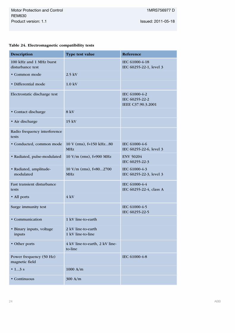
Table 24. Electromagnetic compatibility tests
Description Type test value Reference
100 kHz and 1 MHz burstdisturbance test
IEC 61000-4-18IEC 60255-22-1, level 3
• Common mode 2.5 kV
• Differential mode 1.0 kV
Electrostatic discharge test IEC 61000-4-2IEC 60255-22-2IEEE C37.90.3.2001
• Contact discharge 8 kV
• Air discharge 15 kV
Radio frequency interferencetests
• Conducted, common mode 10 V (rms), f=150 kHz...80MHz
IEC 61000-4-6IEC 60255-22-6, level 3
• Radiated, pulse-modulated 10 V/m (rms), f=900 MHz ENV 50204IEC 60255-22-3
• Radiated, amplitude-modulated
10 V/m (rms), f=80...2700MHz
IEC 61000-4-3IEC 60255-22-3, level 3
Fast transient disturbancetests
IEC 61000-4-4IEC 60255-22-4, class A
• All ports 4 kV
Surge immunity test IEC 61000-4-5IEC 60255-22-5
• Communication 1 kV line-to-earth
• Binary inputs, voltageinputs
2 kV line-to-earth1 kV line-to-line
• Other ports 4 kV line-to-earth, 2 kV line-to-line
Power frequency (50 Hz)magnetic field
IEC 61000-4-8
• 1...3 s 1000 A/m
• Continuous 300 A/m
Motor Protection and Control 1MRS756977 DREM630Product version: 1.1 Issued: 2011-05-18
24 ABB
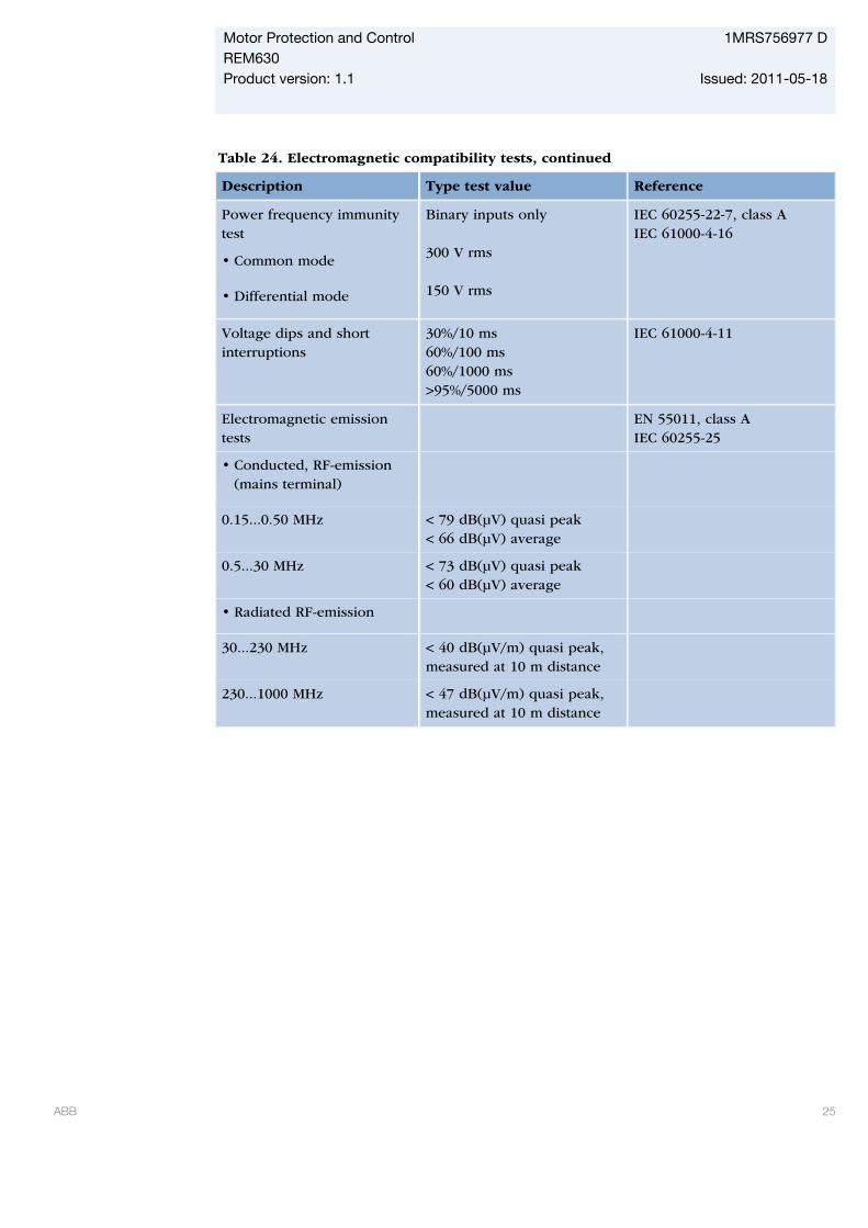
Table 24. Electromagnetic compatibility tests, continued
Description Type test value Reference
Power frequency immunitytest
• Common mode
• Differential mode
Binary inputs only 300 V rms 150 V rms
IEC 60255-22-7, class AIEC 61000-4-16
Voltage dips and shortinterruptions
30%/10 ms60%/100 ms60%/1000 ms>95%/5000 ms
IEC 61000-4-11
Electromagnetic emissiontests
EN 55011, class AIEC 60255-25
• Conducted, RF-emission(mains terminal)
0.15...0.50 MHz < 79 dB(µV) quasi peak< 66 dB(µV) average
0.5...30 MHz < 73 dB(µV) quasi peak< 60 dB(µV) average
• Radiated RF-emission
30...230 MHz < 40 dB(µV/m) quasi peak,measured at 10 m distance
230...1000 MHz < 47 dB(µV/m) quasi peak,measured at 10 m distance
Motor Protection and Control 1MRS756977 DREM630Product version: 1.1 Issued: 2011-05-18
ABB 25
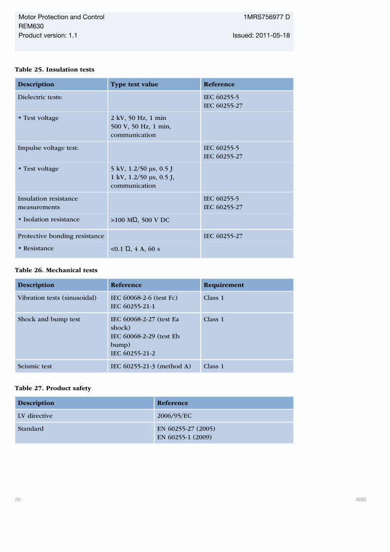
Table 25. Insulation tests
Description Type test value Reference
Dielectric tests: IEC 60255-5IEC 60255-27
• Test voltage 2 kV, 50 Hz, 1 min500 V, 50 Hz, 1 min,communication
Impulse voltage test: IEC 60255-5IEC 60255-27
• Test voltage 5 kV, 1.2/50 μs, 0.5 J1 kV, 1.2/50 μs, 0.5 J,communication
Insulation resistancemeasurements
IEC 60255-5IEC 60255-27
• Isolation resistance >100 MΏ, 500 V DC
Protective bonding resistance IEC 60255-27
• Resistance <0.1 Ώ, 4 A, 60 s
Table 26. Mechanical tests
Description Reference Requirement
Vibration tests (sinusoidal) IEC 60068-2-6 (test Fc)IEC 60255-21-1
Class 1
Shock and bump test IEC 60068-2-27 (test Eashock)IEC 60068-2-29 (test Ebbump)IEC 60255-21-2
Class 1
Seismic test IEC 60255-21-3 (method A) Class 1
Table 27. Product safety
Description Reference
LV directive 2006/95/EC
Standard EN 60255-27 (2005)EN 60255-1 (2009)
Motor Protection and Control 1MRS756977 DREM630Product version: 1.1 Issued: 2011-05-18
26 ABB

Table 28. EMC compliance
Description Reference
EMC directive 2004/108/EC
Standard EN 50263 (2000)EN 60255-26 (2007)
Table 29. RoHS compliance
Description
Complies with RoHS directive 2002/95/EC
Motor Protection and Control 1MRS756977 DREM630Product version: 1.1 Issued: 2011-05-18
ABB 27
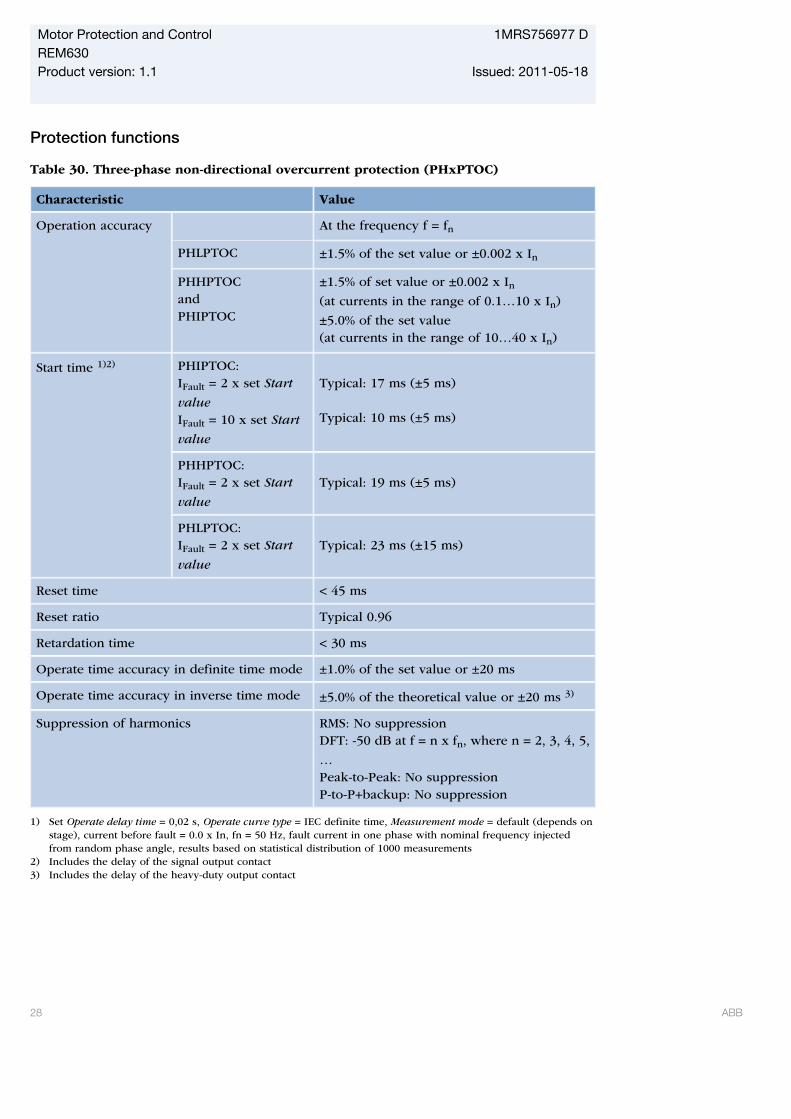
Protection functions
Table 30. Three-phase non-directional overcurrent protection (PHxPTOC)
Characteristic Value
Operation accuracy At the frequency f = fn
PHLPTOC ±1.5% of the set value or ±0.002 x In
PHHPTOCandPHIPTOC
±1.5% of set value or ±0.002 x In(at currents in the range of 0.1…10 x In)
±5.0% of the set value(at currents in the range of 10…40 x In)
Start time 1)2) PHIPTOC:IFault = 2 x set Start
valueIFault = 10 x set Start
value
Typical: 17 ms (±5 ms) Typical: 10 ms (±5 ms)
PHHPTOC:IFault = 2 x set Start
value
Typical: 19 ms (±5 ms)
PHLPTOC:IFault = 2 x set Start
value
Typical: 23 ms (±15 ms)
Reset time < 45 ms
Reset ratio Typical 0.96
Retardation time < 30 ms
Operate time accuracy in definite time mode ±1.0% of the set value or ±20 ms
Operate time accuracy in inverse time mode ±5.0% of the theoretical value or ±20 ms 3)
Suppression of harmonics RMS: No suppressionDFT: -50 dB at f = n x fn, where n = 2, 3, 4, 5,
…Peak-to-Peak: No suppressionP-to-P+backup: No suppression
1) Set Operate delay time = 0,02 s, Operate curve type = IEC definite time, Measurement mode = default (depends onstage), current before fault = 0.0 x In, fn = 50 Hz, fault current in one phase with nominal frequency injectedfrom random phase angle, results based on statistical distribution of 1000 measurements
2) Includes the delay of the signal output contact3) Includes the delay of the heavy-duty output contact
Motor Protection and Control 1MRS756977 DREM630Product version: 1.1 Issued: 2011-05-18
28 ABB

Table 31. Three-phase non-directional overcurrent protection (PHxPTOC) main settings
Parameter Function Value (Range) Step
Start Value PHLPTOC 0.05...5.00 pu 0.01
PHHPTOC 0.10...40.00 pu 0.01
PHIPTOC 0.10...40.00 pu 0.01
Time multiplier PHLPTOC 0.05...15.00 0.05
PHHPTOC 0.05...15.00 0.05
Operate delay time PHLPTOC 0.04…200.00 s 0.01
PHHPTOC 0.02…200.00 s 0.01
PHIPTOC 0.02…200.00 s 0.01
Operating curve
type1)
PHLPTOC Definite or inverse timeCurve type: 1, 2, 3, 4, 5, 6, 7, 8, 9, 10, 11, 12,13, 14, 15, 17, 18, 19
PHHPTOC Definite or inverse timeCurve type: 1, 3, 5, 9, 10, 12, 15, 17
PHIPTOC Definite time
1) For further reference please refer to the Operating characteristics table
Motor Protection and Control 1MRS756977 DREM630Product version: 1.1 Issued: 2011-05-18
ABB 29
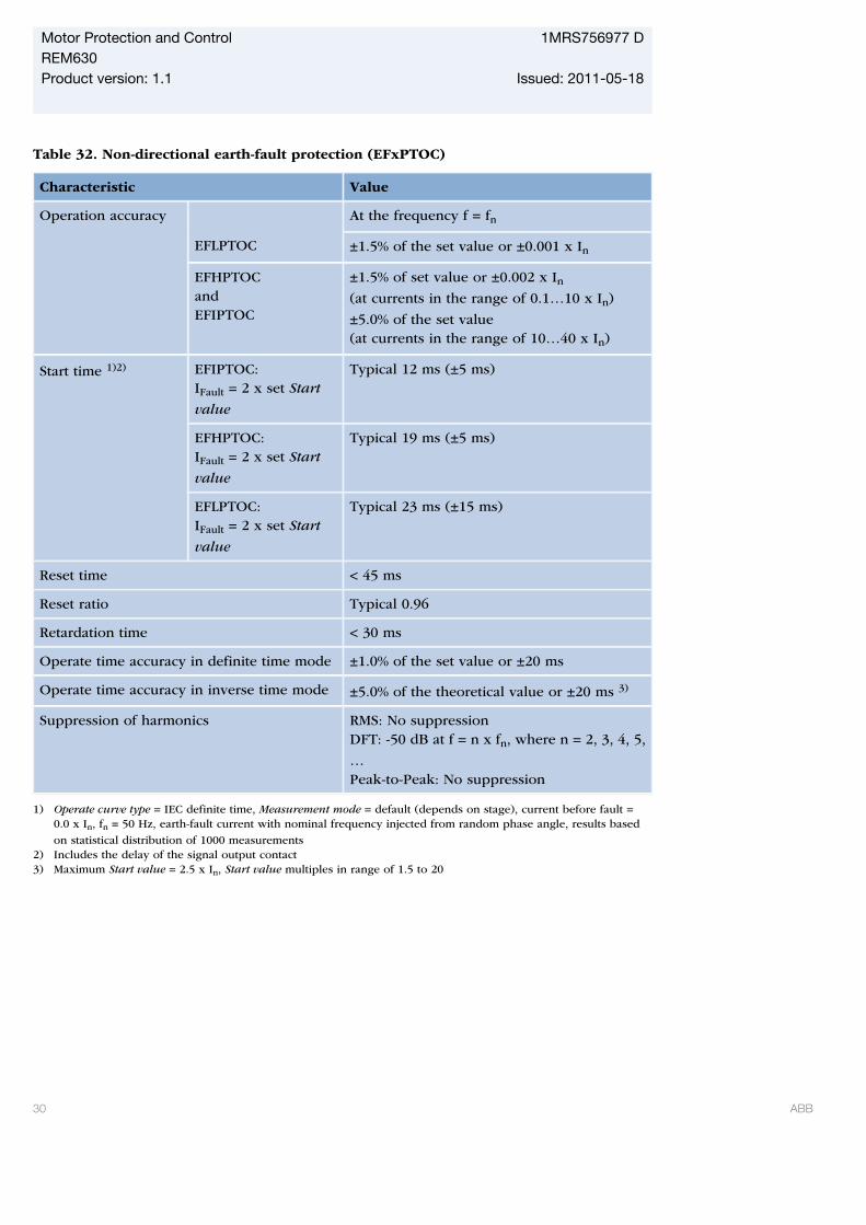
Table 32. Non-directional earth-fault protection (EFxPTOC)
Characteristic Value
Operation accuracy At the frequency f = fn
EFLPTOC ±1.5% of the set value or ±0.001 x In
EFHPTOCandEFIPTOC
±1.5% of set value or ±0.002 x In(at currents in the range of 0.1…10 x In)
±5.0% of the set value(at currents in the range of 10…40 x In)
Start time 1)2) EFIPTOC:IFault = 2 x set Start
value
Typical 12 ms (±5 ms)
EFHPTOC:IFault = 2 x set Start
value
Typical 19 ms (±5 ms)
EFLPTOC:IFault = 2 x set Start
value
Typical 23 ms (±15 ms)
Reset time < 45 ms
Reset ratio Typical 0.96
Retardation time < 30 ms
Operate time accuracy in definite time mode ±1.0% of the set value or ±20 ms
Operate time accuracy in inverse time mode ±5.0% of the theoretical value or ±20 ms 3)
Suppression of harmonics RMS: No suppressionDFT: -50 dB at f = n x fn, where n = 2, 3, 4, 5,
…Peak-to-Peak: No suppression
1) Operate curve type = IEC definite time, Measurement mode = default (depends on stage), current before fault =0.0 x In, fn = 50 Hz, earth-fault current with nominal frequency injected from random phase angle, results based
on statistical distribution of 1000 measurements2) Includes the delay of the signal output contact3) Maximum Start value = 2.5 x In, Start value multiples in range of 1.5 to 20
Motor Protection and Control 1MRS756977 DREM630Product version: 1.1 Issued: 2011-05-18
30 ABB
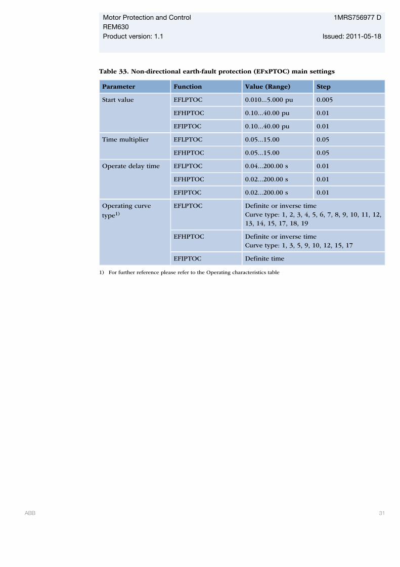
Table 33. Non-directional earth-fault protection (EFxPTOC) main settings
Parameter Function Value (Range) Step
Start value EFLPTOC 0.010...5.000 pu 0.005
EFHPTOC 0.10...40.00 pu 0.01
EFIPTOC 0.10...40.00 pu 0.01
Time multiplier EFLPTOC 0.05...15.00 0.05
EFHPTOC 0.05...15.00 0.05
Operate delay time EFLPTOC 0.04...200.00 s 0.01
EFHPTOC 0.02...200.00 s 0.01
EFIPTOC 0.02...200.00 s 0.01
Operating curve
type1)
EFLPTOC Definite or inverse timeCurve type: 1, 2, 3, 4, 5, 6, 7, 8, 9, 10, 11, 12,13, 14, 15, 17, 18, 19
EFHPTOC Definite or inverse timeCurve type: 1, 3, 5, 9, 10, 12, 15, 17
EFIPTOC Definite time
1) For further reference please refer to the Operating characteristics table
Motor Protection and Control 1MRS756977 DREM630Product version: 1.1 Issued: 2011-05-18
ABB 31
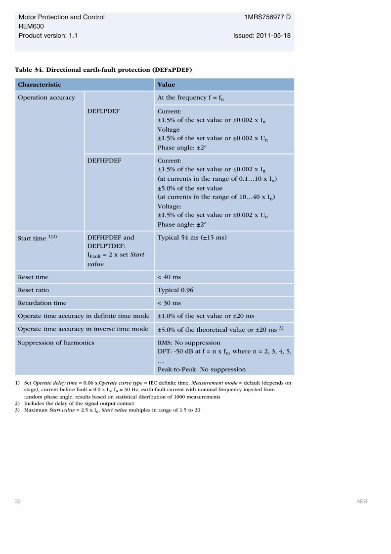
Table 34. Directional earth-fault protection (DEFxPDEF)
Characteristic Value
Operation accuracy At the frequency f = fn
DEFLPDEF Current:±1.5% of the set value or ±0.002 x InVoltage±1.5% of the set value or ±0.002 x Un
Phase angle: ±2°
DEFHPDEF Current:±1.5% of the set value or ±0.002 x In(at currents in the range of 0.1…10 x In)
±5.0% of the set value(at currents in the range of 10…40 x In)
Voltage:±1.5% of the set value or ±0.002 x Un
Phase angle: ±2°
Start time 1)2) DEFHPDEF andDEFLPTDEF:IFault = 2 x set Start
value
Typical 54 ms (±15 ms)
Reset time < 40 ms
Reset ratio Typical 0.96
Retardation time < 30 ms
Operate time accuracy in definite time mode ±1.0% of the set value or ±20 ms
Operate time accuracy in inverse time mode ±5.0% of the theoretical value or ±20 ms 3)
Suppression of harmonics RMS: No suppressionDFT: -50 dB at f = n x fn, where n = 2, 3, 4, 5,
…Peak-to-Peak: No suppression
1) Set Operate delay time = 0.06 s,Operate curve type = IEC definite time, Measurement mode = default (depends onstage), current before fault = 0.0 x In, fn = 50 Hz, earth-fault current with nominal frequency injected from
random phase angle, results based on statistical distribution of 1000 measurements2) Includes the delay of the signal output contact3) Maximum Start value = 2.5 x In, Start value multiples in range of 1.5 to 20
Motor Protection and Control 1MRS756977 DREM630Product version: 1.1 Issued: 2011-05-18
32 ABB

Table 35. Directional earth-fault protection (DEFxPDEF) main settings
Parameter Function Value (Range) Step
Start Value DEFLPDEF 0.010...5.000 pu 0.005
DEFHPDEF 0.10...40.00 pu 0.01
Directional mode DEFLPDEF andDEFHPDEF
1=Non-directional2=Forward3=Reverse
Time multiplier DEFLPDEF 0.05...15.00 0.05
DEFHPDEF 0.05...15.00 0.05
Operate delay time DEFLPDEF 0.06...200.00 s 0.01
DEFHPDEF 0.06...200.00 s 0.01
Operating curve
type1)
DEFLPDEF Definite or inverse timeCurve type: 1, 2, 3, 4, 5, 6, 7, 8, 9, 10, 11, 12,13, 14, 15, 17, 18, 19
DEFHPDEF Definite or inverse timeCurve type: 1, 3, 5, 15, 17
Operation mode DEFLPDEF andDEFHPDEF
1=Phase angle2=IoSin3=IoCos4=Phase angle 805=Phase angle 88
1) For further reference, refer to the Operating characteristics table
Table 36. Rotor earth-fault protection (MREFPTOC)
Characteristic Value
Operation accuracy Depending on the frequency of the currentmeasured f=fn ± 2 Hz
±1.5% of the set value or ±0.002 x In
Start time1)2) Typical 25 ms (+-15ms)
Reset time < 50 ms
Reset ratio Typical 0.96
Retardation time < 50 ms
Operate time accuracy ±1.0% of the set value of ±20 ms
Suppression of harmonics -50dB at f = n x fn, where n = 2, 3, 4, 5,…
1) Current before fault = 0.0 x In, fn = 50 Hz, earth-fault current with nominal frequency injected from randomphase angle, results based on statistical distribution of 1000 measurements.
2) Includes the delay of the signal output contact.
Motor Protection and Control 1MRS756977 DREM630Product version: 1.1 Issued: 2011-05-18
ABB 33
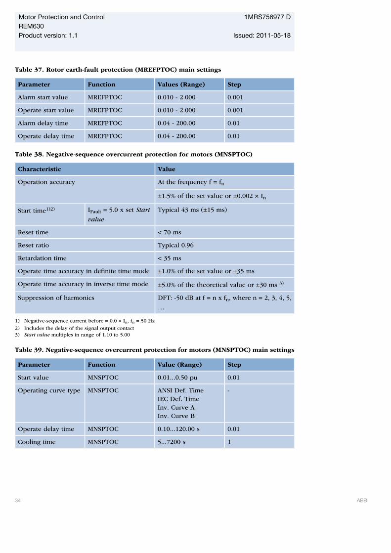
Table 37. Rotor earth-fault protection (MREFPTOC) main settings
Parameter Function Values (Range) Step
Alarm start value MREFPTOC 0.010 - 2.000 0.001
Operate start value MREFPTOC 0.010 - 2.000 0.001
Alarm delay time MREFPTOC 0.04 - 200.00 0.01
Operate delay time MREFPTOC 0.04 - 200.00 0.01
Table 38. Negative-sequence overcurrent protection for motors (MNSPTOC)
Characteristic Value
Operation accuracy At the frequency f = fn
±1.5% of the set value or ±0.002 × In
Start time1)2) IFault = 5.0 x set Start
value
Typical 43 ms (±15 ms)
Reset time < 70 ms
Reset ratio Typical 0.96
Retardation time < 35 ms
Operate time accuracy in definite time mode ±1.0% of the set value or ±35 ms
Operate time accuracy in inverse time mode ±5.0% of the theoretical value or ±30 ms 3)
Suppression of harmonics DFT: -50 dB at f = n x fn, where n = 2, 3, 4, 5,
…
1) Negative-sequence current before = 0.0 × In, fn = 50 Hz
2) Includes the delay of the signal output contact3) Start value multiples in range of 1.10 to 5.00
Table 39. Negative-sequence overcurrent protection for motors (MNSPTOC) main settings
Parameter Function Value (Range) Step
Start value MNSPTOC 0.01...0.50 pu 0.01
Operating curve type MNSPTOC ANSI Def. TimeIEC Def. TimeInv. Curve AInv. Curve B
-
Operate delay time MNSPTOC 0.10...120.00 s 0.01
Cooling time MNSPTOC 5...7200 s 1
Motor Protection and Control 1MRS756977 DREM630Product version: 1.1 Issued: 2011-05-18
34 ABB
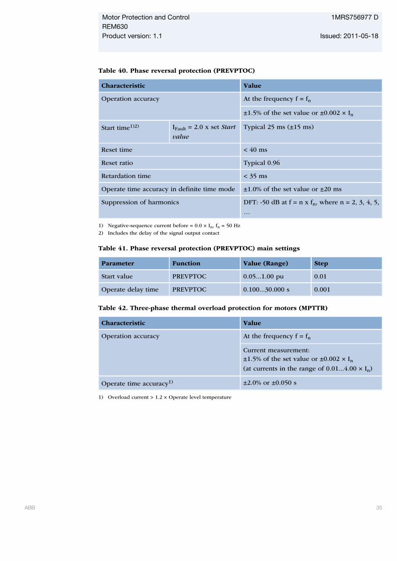
Table 40. Phase reversal protection (PREVPTOC)
Characteristic Value
Operation accuracy At the frequency f = fn
±1.5% of the set value or ±0.002 × In
Start time1)2) IFault = 2.0 x set Start
value
Typical 25 ms (±15 ms)
Reset time < 40 ms
Reset ratio Typical 0.96
Retardation time < 35 ms
Operate time accuracy in definite time mode ±1.0% of the set value or ±20 ms
Suppression of harmonics DFT: -50 dB at f = n x fn, where n = 2, 3, 4, 5,
…
1) Negative-sequence current before = 0.0 × In, fn = 50 Hz
2) Includes the delay of the signal output contact
Table 41. Phase reversal protection (PREVPTOC) main settings
Parameter Function Value (Range) Step
Start value PREVPTOC 0.05...1.00 pu 0.01
Operate delay time PREVPTOC 0.100...30.000 s 0.001
Table 42. Three-phase thermal overload protection for motors (MPTTR)
Characteristic Value
Operation accuracy At the frequency f = fn
Current measurement:±1.5% of the set value or ±0.002 × In(at currents in the range of 0.01...4.00 × In)
Operate time accuracy1) ±2.0% or ±0.050 s
1) Overload current > 1.2 × Operate level temperature
Motor Protection and Control 1MRS756977 DREM630Product version: 1.1 Issued: 2011-05-18
ABB 35

Table 43. Three-phase thermal overload protection for motors (MPTTR) main settings
Parameter Function Value (Range) Step
Env temperaturemode
MPTTR FLC OnlyUse RTDSet Amb Temp
-
Env temperature set MPTTR -20.0...70.0 deg 0.1
Alarm thermal value MPTTR 50.0...100.0 % 0.1
Restart thermal value MPTTR 20.0...80.0 % 0.1
Overload factor MPTTR 1.00...1.20 0.01
Weighting factor p MPTTR 20.0...100.0 0.1
Time constant normal MPTTR 80...4000 s 1
Time constant start MPTTR 80...4000 s 1
Table 44. Motor start-up supervision (STTPMSU)
Characteristic Value
Operation accuracy At the frequency f = fn
±1.5% of the set value or ±0.002 × In
Start time1)2) IFault = 1.1 × set Start
detection A
Typical 25 ms (± 15ms)
Operate time accuracy ±1.0% of the set value or ±20 ms
Reset ratio Typical 0.90
1) Current before = 0.0 x In, fn = 50 Hz, overcurrent in one phase
2) Includes the delay of the signal output contact
Table 45. Motor start-up supervision (STTPMSU) main settings
Parameter Function Value (Range) Step
Motor start-up A STTPMSU 1.0...10.0 pu 0.1
Motor start-up time STTPMSU 0.3...80.0 s 0.1
Lock rotor time STTPMSU 2.0...120.0 s 1.0
Operation mode STTPMSU IItIIt, CBIIt & stallIIt & stall, CB
-
Restart inhibit time STTPMSU 0...250 min 1
Motor Protection and Control 1MRS756977 DREM630Product version: 1.1 Issued: 2011-05-18
36 ABB
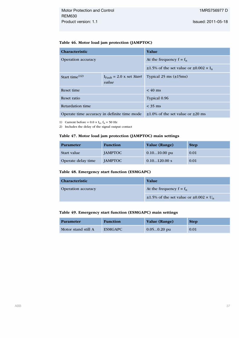
Table 46. Motor load jam protection (JAMPTOC)
Characteristic Value
Operation accuracy At the frequency f = fn
±1.5% of the set value or ±0.002 × In
Start time1)2) IFault = 2.0 x set Start
value
Typical 25 ms (±15ms)
Reset time < 40 ms
Reset ratio Typical 0.96
Retardation time < 35 ms
Operate time accuracy in definite time mode ±1.0% of the set value or ±20 ms
1) Current before = 0.0 × In, fn = 50 Hz
2) Includes the delay of the signal output contact
Table 47. Motor load jam protection (JAMPTOC) main settings
Parameter Function Value (Range) Step
Start value JAMPTOC 0.10...10.00 pu 0.01
Operate delay time JAMPTOC 0.10...120.00 s 0.01
Table 48. Emergency start function (ESMGAPC)
Characteristic Value
Operation accuracy At the frequency f = fn
±1.5% of the set value or ±0.002 × Un
Table 49. Emergency start function (ESMGAPC) main settings
Parameter Function Value (Range) Step
Motor stand still A ESMGAPC 0.05...0.20 pu 0.01
Motor Protection and Control 1MRS756977 DREM630Product version: 1.1 Issued: 2011-05-18
ABB 37
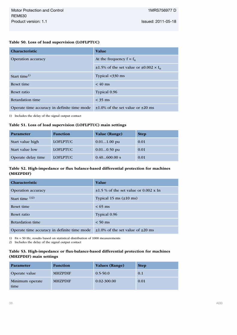
Table 50. Loss of load supervision (LOFLPTUC)
Characteristic Value
Operation accuracy At the frequency f = fn
±1.5% of the set value or ±0.002 × In
Start time1) Typical <330 ms
Reset time < 40 ms
Reset ratio Typical 0.96
Retardation time < 35 ms
Operate time accuracy in definite time mode ±1.0% of the set value or ±20 ms
1) Includes the delay of the signal output contact
Table 51. Loss of load supervision (LOFLPTUC) main settings
Parameter Function Value (Range) Step
Start value high LOFLPTUC 0.01...1.00 pu 0.01
Start value low LOFLPTUC 0.01...0.50 pu 0.01
Operate delay time LOFLPTUC 0.40...600.00 s 0.01
Table 52. High-impedance or flux balance-based differential protection for machines(MHZPDIF)
Characteristic Value
Operation accuracy ±1.5 % of the set value or 0.002 x In
Start time 1)2) Typical 15 ms (±10 ms)
Reset time < 65 ms
Reset ratio Typical 0.96
Retardation time < 50 ms
Operate time accuracy in definite time mode ±1.0% of the set value of ±20 ms
1) Fn = 50 Hz, results based on statistical distribution of 1000 measurements2) Includes the delay of the signal output contact
Table 53. High-impedance or flux-balance-based differential protection for machines(MHZPDIF) main settings
Parameter Function Values (Range) Step
Operate value MHZPDIF 0.5-50.0 0.1
Minimum operatetime
MHZPDIF 0.02-300.00 0.01
Motor Protection and Control 1MRS756977 DREM630Product version: 1.1 Issued: 2011-05-18
38 ABB
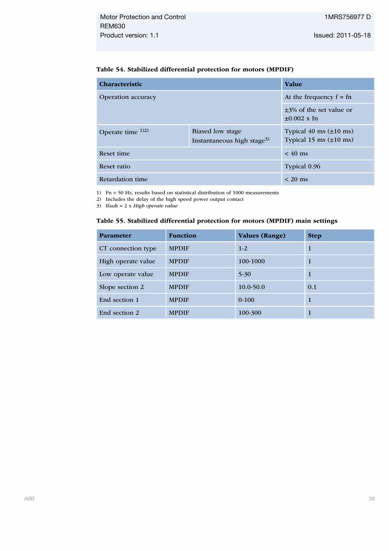
Table 54. Stabilized differential protection for motors (MPDIF)
Characteristic Value
Operation accuracy At the frequency f = fn
±3% of the set value or±0.002 x In
Operate time 1)2) Biased low stage
Instantaneous high stage3)
Typical 40 ms (±10 ms)Typical 15 ms (±10 ms)
Reset time < 40 ms
Reset ratio Typical 0.96
Retardation time < 20 ms
1) Fn = 50 Hz, results based on statistical distribution of 1000 measurements2) Includes the delay of the high speed power output contact3) Ifault = 2 x High operate value
Table 55. Stabilized differential protection for motors (MPDIF) main settings
Parameter Function Values (Range) Step
CT connection type MPDIF 1-2 1
High operate value MPDIF 100-1000 1
Low operate value MPDIF 5-30 1
Slope section 2 MPDIF 10.0-50.0 0.1
End section 1 MPDIF 0-100 1
End section 2 MPDIF 100-300 1
Motor Protection and Control 1MRS756977 DREM630Product version: 1.1 Issued: 2011-05-18
ABB 39

Table 56. Three-phase overvoltage protection (PHPTOV)
Characteristic Value
Operation accuracy At the frequency f = fn
±1.5% of the set value or ±0.002 × Un
Start time1)2) UFault = 2.0 x set Start
value
Typical 17 ms (±15 ms)
Reset time < 40 ms
Reset ratio Depends of the set Relative hysteresis
Retardation time < 35 ms
Operate time accuracy in definite time mode ±1.0% of the set value or ±20 ms
Operate time accuracy in inverse time mode ±5.0% of the theoretical value or ±20 ms3)
Suppression of harmonics DFT: -50 dB at f = n × fn, where n = 2, 3, 4, 5,
…
1) Start value = 1.0 × Un, Voltage before fault = 0.9 × Un, fn = 50 Hz, overvoltage in one phase-to-phase with
nominal frequency injected from random phase angle2) Includes the delay of the signal output contact3) Maximum Start value = 1.20 × Un, Start value multiples in range of 1.10 to 2.00
Table 57. Three-phase overvoltage protection (PHPTOV) main settings
Parameter Function Value (Range) Step
Start value PHPTOV 0.05...1.60 pu 0.01
Time multiplier PHPTOV 0.05...15.00 0.05
Operate delay time PHPTOV 0.40...300.000 s 0.10
Operating curve
type1)
PHPTOV Definite or inverse timeCurve type: 5, 15, 17, 18, 19, 20
1) For further reference please refer to the Operating characteristics table
Motor Protection and Control 1MRS756977 DREM630Product version: 1.1 Issued: 2011-05-18
40 ABB
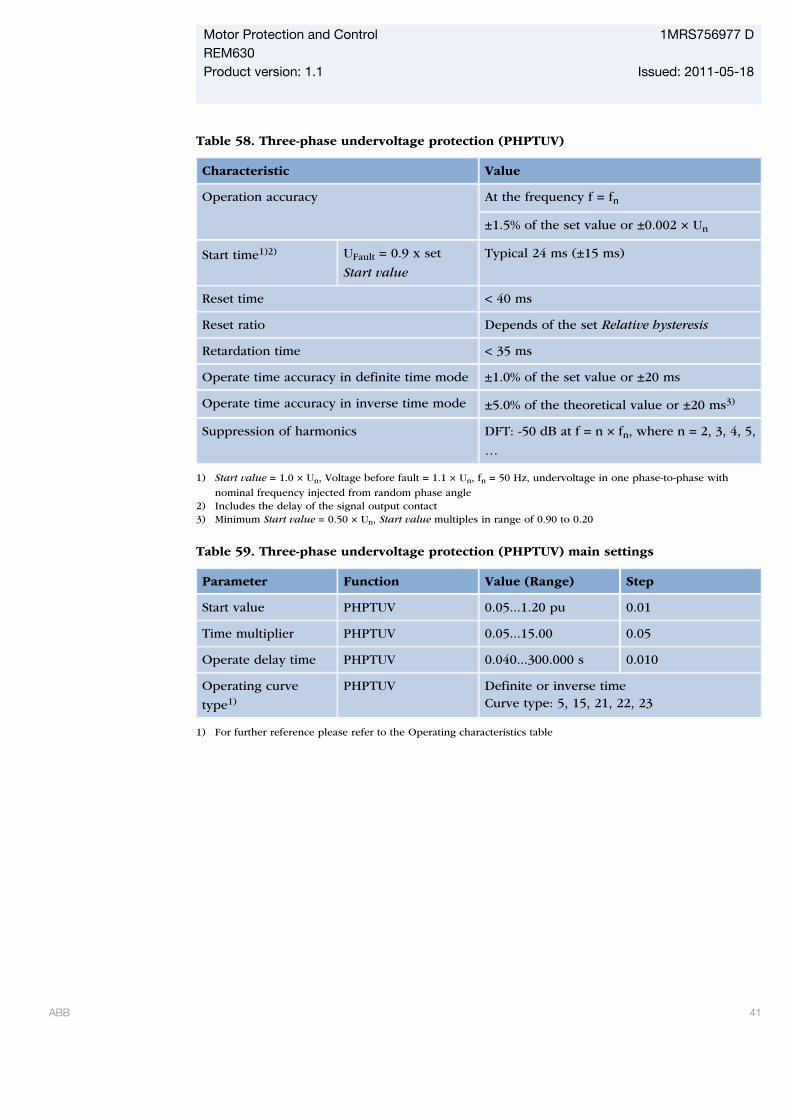
Table 58. Three-phase undervoltage protection (PHPTUV)
Characteristic Value
Operation accuracy At the frequency f = fn
±1.5% of the set value or ±0.002 × Un
Start time1)2) UFault = 0.9 x set
Start value
Typical 24 ms (±15 ms)
Reset time < 40 ms
Reset ratio Depends of the set Relative hysteresis
Retardation time < 35 ms
Operate time accuracy in definite time mode ±1.0% of the set value or ±20 ms
Operate time accuracy in inverse time mode ±5.0% of the theoretical value or ±20 ms3)
Suppression of harmonics DFT: -50 dB at f = n × fn, where n = 2, 3, 4, 5,
…
1) Start value = 1.0 × Un, Voltage before fault = 1.1 × Un, fn = 50 Hz, undervoltage in one phase-to-phase with
nominal frequency injected from random phase angle2) Includes the delay of the signal output contact3) Minimum Start value = 0.50 × Un, Start value multiples in range of 0.90 to 0.20
Table 59. Three-phase undervoltage protection (PHPTUV) main settings
Parameter Function Value (Range) Step
Start value PHPTUV 0.05...1.20 pu 0.01
Time multiplier PHPTUV 0.05...15.00 0.05
Operate delay time PHPTUV 0.040...300.000 s 0.010
Operating curve
type1)
PHPTUV Definite or inverse timeCurve type: 5, 15, 21, 22, 23
1) For further reference please refer to the Operating characteristics table
Motor Protection and Control 1MRS756977 DREM630Product version: 1.1 Issued: 2011-05-18
ABB 41
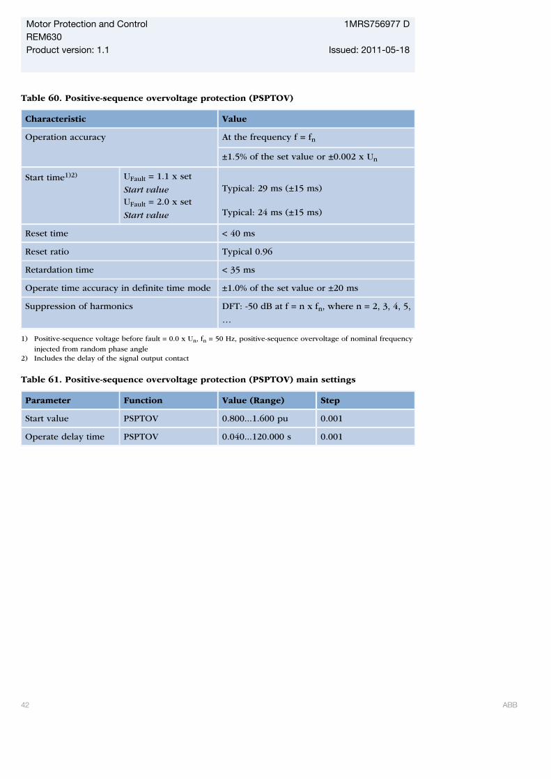
Table 60. Positive-sequence overvoltage protection (PSPTOV)
Characteristic Value
Operation accuracy At the frequency f = fn
±1.5% of the set value or ±0.002 x Un
Start time1)2) UFault = 1.1 x set
Start valueUFault = 2.0 x set
Start value
Typical: 29 ms (±15 ms) Typical: 24 ms (±15 ms)
Reset time < 40 ms
Reset ratio Typical 0.96
Retardation time < 35 ms
Operate time accuracy in definite time mode ±1.0% of the set value or ±20 ms
Suppression of harmonics DFT: -50 dB at f = n x fn, where n = 2, 3, 4, 5,
…
1) Positive-sequence voltage before fault = 0.0 x Un, fn = 50 Hz, positive-sequence overvoltage of nominal frequency
injected from random phase angle2) Includes the delay of the signal output contact
Table 61. Positive-sequence overvoltage protection (PSPTOV) main settings
Parameter Function Value (Range) Step
Start value PSPTOV 0.800...1.600 pu 0.001
Operate delay time PSPTOV 0.040...120.000 s 0.001
Motor Protection and Control 1MRS756977 DREM630Product version: 1.1 Issued: 2011-05-18
42 ABB

Table 62. Positive-sequence undervoltage protection (PSPTUV)
Characteristic Value
Operation accuracy At the frequency f = fn
±1.5% of the set value or ±0.002 × Un
Start time1)2) UFault = 0.9 x set Start
value
Typical 28 ms (±15 ms)
Reset time < 40 ms
Reset ratio Typical 0.96
Retardation time < 35 ms
Operate time accuracy in definite time mode ±1.0% of the set value or ±20 ms
Suppression of harmonics DFT: -50 dB at f = n × fn, where n = 2, 3, 4, 5,
…
1) Residual voltage before fault = 1.1 × Un, fn = 50 Hz, residual voltage with nominal frequency injected from
random phase angle2) Includes the delay of the signal output contact
Table 63. Positive-sequence undervoltage protection (PSPTUV) main settings
Parameter Function Value (Range) Step
Start value PSPTUV 0.010...1.200 pu 0.001
Operate delay time PSPTUV 0.040...120.000 s 0.001
Voltage block value PSPTUV 0.01...1.0 pu 0.01
Motor Protection and Control 1MRS756977 DREM630Product version: 1.1 Issued: 2011-05-18
ABB 43
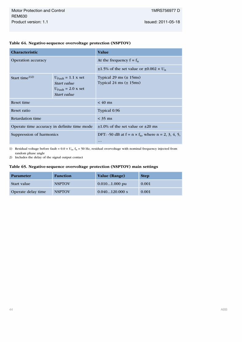
Table 64. Negative-sequence overvoltage protection (NSPTOV)
Characteristic Value
Operation accuracy At the frequency f = fn
±1.5% of the set value or ±0.002 × Un
Start time1)2) UFault = 1.1 x set
Start valueUFault = 2.0 x set
Start value
Typical 29 ms (± 15ms)Typical 24 ms (± 15ms)
Reset time < 40 ms
Reset ratio Typical 0.96
Retardation time < 35 ms
Operate time accuracy in definite time mode ±1.0% of the set value or ±20 ms
Suppression of harmonics DFT: -50 dB at f = n × fn, where n = 2, 3, 4, 5,
…
1) Residual voltage before fault = 0.0 × Un, fn = 50 Hz, residual overvoltage with nominal frequency injected from
random phase angle2) Includes the delay of the signal output contact
Table 65. Negative-sequence overvoltage protection (NSPTOV) main settings
Parameter Function Value (Range) Step
Start value NSPTOV 0.010...1.000 pu 0.001
Operate delay time NSPTOV 0.040...120.000 s 0.001
Motor Protection and Control 1MRS756977 DREM630Product version: 1.1 Issued: 2011-05-18
44 ABB
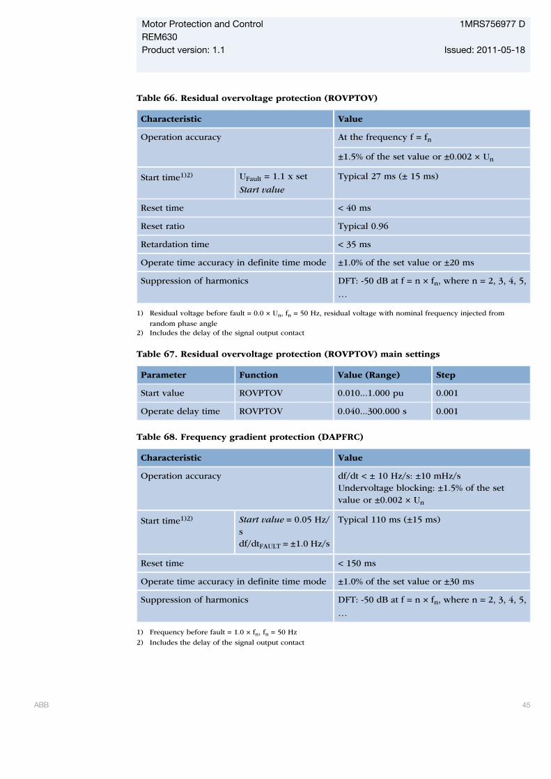
Table 66. Residual overvoltage protection (ROVPTOV)
Characteristic Value
Operation accuracy At the frequency f = fn
±1.5% of the set value or ±0.002 × Un
Start time1)2) UFault = 1.1 x set
Start value
Typical 27 ms (± 15 ms)
Reset time < 40 ms
Reset ratio Typical 0.96
Retardation time < 35 ms
Operate time accuracy in definite time mode ±1.0% of the set value or ±20 ms
Suppression of harmonics DFT: -50 dB at f = n × fn, where n = 2, 3, 4, 5,
…
1) Residual voltage before fault = 0.0 × Un, fn = 50 Hz, residual voltage with nominal frequency injected from
random phase angle2) Includes the delay of the signal output contact
Table 67. Residual overvoltage protection (ROVPTOV) main settings
Parameter Function Value (Range) Step
Start value ROVPTOV 0.010...1.000 pu 0.001
Operate delay time ROVPTOV 0.040...300.000 s 0.001
Table 68. Frequency gradient protection (DAPFRC)
Characteristic Value
Operation accuracy df/dt < ± 10 Hz/s: ±10 mHz/sUndervoltage blocking: ±1.5% of the setvalue or ±0.002 × Un
Start time1)2) Start value = 0.05 Hz/sdf/dtFAULT = ±1.0 Hz/s
Typical 110 ms (±15 ms)
Reset time < 150 ms
Operate time accuracy in definite time mode ±1.0% of the set value or ±30 ms
Suppression of harmonics DFT: -50 dB at f = n × fn, where n = 2, 3, 4, 5,
…
1) Frequency before fault = 1.0 × fn, fn = 50 Hz
2) Includes the delay of the signal output contact
Motor Protection and Control 1MRS756977 DREM630Product version: 1.1 Issued: 2011-05-18
ABB 45
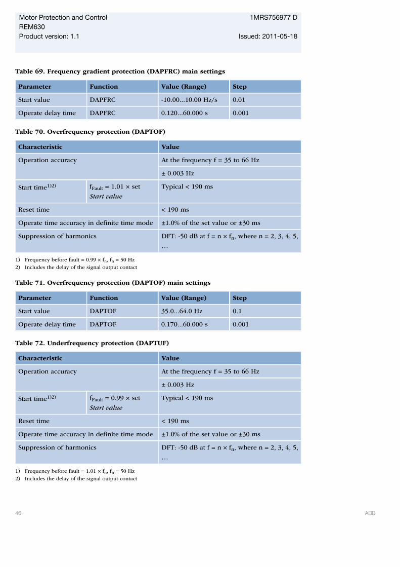
Table 69. Frequency gradient protection (DAPFRC) main settings
Parameter Function Value (Range) Step
Start value DAPFRC -10.00...10.00 Hz/s 0.01
Operate delay time DAPFRC 0.120...60.000 s 0.001
Table 70. Overfrequency protection (DAPTOF)
Characteristic Value
Operation accuracy At the frequency f = 35 to 66 Hz
± 0.003 Hz
Start time1)2) fFault = 1.01 × set
Start value
Typical < 190 ms
Reset time < 190 ms
Operate time accuracy in definite time mode ±1.0% of the set value or ±30 ms
Suppression of harmonics DFT: -50 dB at f = n × fn, where n = 2, 3, 4, 5,
…
1) Frequency before fault = 0.99 × fn, fn = 50 Hz
2) Includes the delay of the signal output contact
Table 71. Overfrequency protection (DAPTOF) main settings
Parameter Function Value (Range) Step
Start value DAPTOF 35.0...64.0 Hz 0.1
Operate delay time DAPTOF 0.170...60.000 s 0.001
Table 72. Underfrequency protection (DAPTUF)
Characteristic Value
Operation accuracy At the frequency f = 35 to 66 Hz
± 0.003 Hz
Start time1)2) fFault = 0.99 × set
Start value
Typical < 190 ms
Reset time < 190 ms
Operate time accuracy in definite time mode ±1.0% of the set value or ±30 ms
Suppression of harmonics DFT: -50 dB at f = n × fn, where n = 2, 3, 4, 5,
…
1) Frequency before fault = 1.01 × fn, fn = 50 Hz
2) Includes the delay of the signal output contact
Motor Protection and Control 1MRS756977 DREM630Product version: 1.1 Issued: 2011-05-18
46 ABB
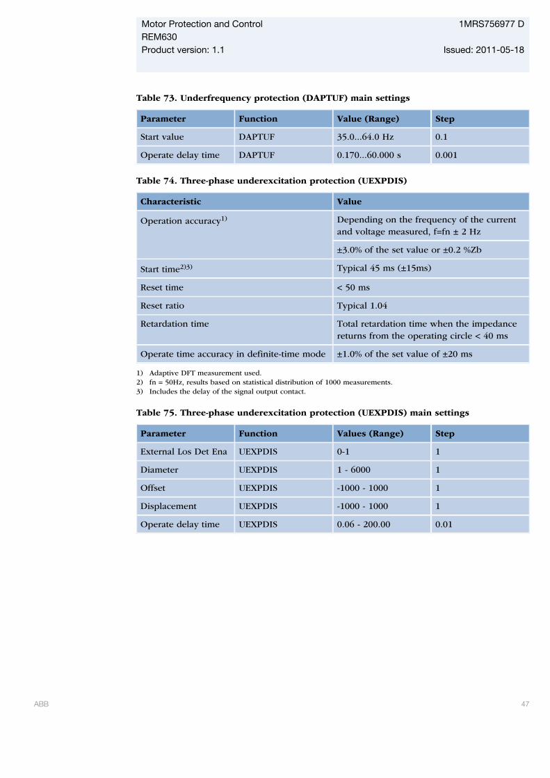
Table 73. Underfrequency protection (DAPTUF) main settings
Parameter Function Value (Range) Step
Start value DAPTUF 35.0...64.0 Hz 0.1
Operate delay time DAPTUF 0.170...60.000 s 0.001
Table 74. Three-phase underexcitation protection (UEXPDIS)
Characteristic Value
Operation accuracy1) Depending on the frequency of the currentand voltage measured, f=fn ± 2 Hz
±3.0% of the set value or ±0.2 %Zb
Start time2)3) Typical 45 ms (±15ms)
Reset time < 50 ms
Reset ratio Typical 1.04
Retardation time Total retardation time when the impedancereturns from the operating circle < 40 ms
Operate time accuracy in definite-time mode ±1.0% of the set value of ±20 ms
1) Adaptive DFT measurement used.2) fn = 50Hz, results based on statistical distribution of 1000 measurements.3) Includes the delay of the signal output contact.
Table 75. Three-phase underexcitation protection (UEXPDIS) main settings
Parameter Function Values (Range) Step
External Los Det Ena UEXPDIS 0-1 1
Diameter UEXPDIS 1 - 6000 1
Offset UEXPDIS -1000 - 1000 1
Displacement UEXPDIS -1000 - 1000 1
Operate delay time UEXPDIS 0.06 - 200.00 0.01
Motor Protection and Control 1MRS756977 DREM630Product version: 1.1 Issued: 2011-05-18
ABB 47
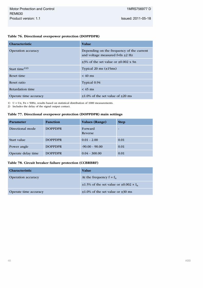
Table 76. Directional overpower protection (DOPPDPR)
Characteristic Value
Operation accuracy Depending on the frequency of the currentand voltage measured f=fn ±2 Hz
±3% of the set value or ±0.002 x Sn
Start time1)2) Typical 20 ms (±15ms)
Reset time < 40 ms
Reset ratio Typical 0.94
Retardation time < 45 ms
Operate time accuracy ±1.0% of the set value of ±20 ms
1) U = Un, Fn = 50Hz, results based on statistical distribution of 1000 measurements.2) Includes the delay of the signal output contact.
Table 77. Directional overpower protection (DOPPDPR) main settings
Parameter Function Values (Range) Step
Directional mode DOPPDPR ForwardReverse
-
Start value DOPPDPR 0.01 - 2.00 0.01
Power angle DOPPDPR -90.00 - 90.00 0.01
Operate delay time DOPPDPR 0.04 - 300.00 0.01
Table 78. Circuit breaker failure protection (CCBRBRF)
Characteristic Value
Operation accuracy At the frequency f = fn
±1.5% of the set value or ±0.002 × In
Operate time accuracy ±1.0% of the set value or ±30 ms
Motor Protection and Control 1MRS756977 DREM630Product version: 1.1 Issued: 2011-05-18
48 ABB
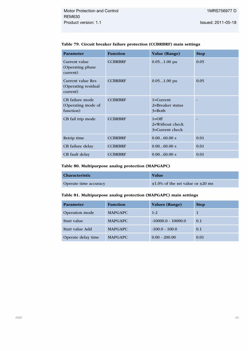
Table 79. Circuit breaker failure protection (CCBRBRF) main settings
Parameter Function Value (Range) Step
Current value(Operating phasecurrent)
CCBRBRF 0.05...1.00 pu 0.05
Current value Res(Operating residualcurrent)
CCBRBRF 0.05...1.00 pu 0.05
CB failure mode(Operating mode offunction)
CCBRBRF 1=Current2=Breaker status3=Both
-
CB fail trip mode CCBRBRF 1=Off2=Without check3=Current check
-
Retrip time CCBRBRF 0.00...60.00 s 0.01
CB failure delay CCBRBRF 0.00...60.00 s 0.01
CB fault delay CCBRBRF 0.00...60.00 s 0.01
Table 80. Multipurpose analog protection (MAPGAPC)
Characteristic Value
Operate time accuracy ±1.0% of the set value or ±20 ms
Table 81. Multipurpose analog protection (MAPGAPC) main settings
Parameter Function Values (Range) Step
Operation mode MAPGAPC 1-2 1
Start value MAPGAPC -10000.0 - 10000.0 0.1
Start value Add MAPGAPC -100.0 - 100.0 0.1
Operate delay time MAPGAPC 0.00 - 200.00 0.01
Motor Protection and Control 1MRS756977 DREM630Product version: 1.1 Issued: 2011-05-18
ABB 49
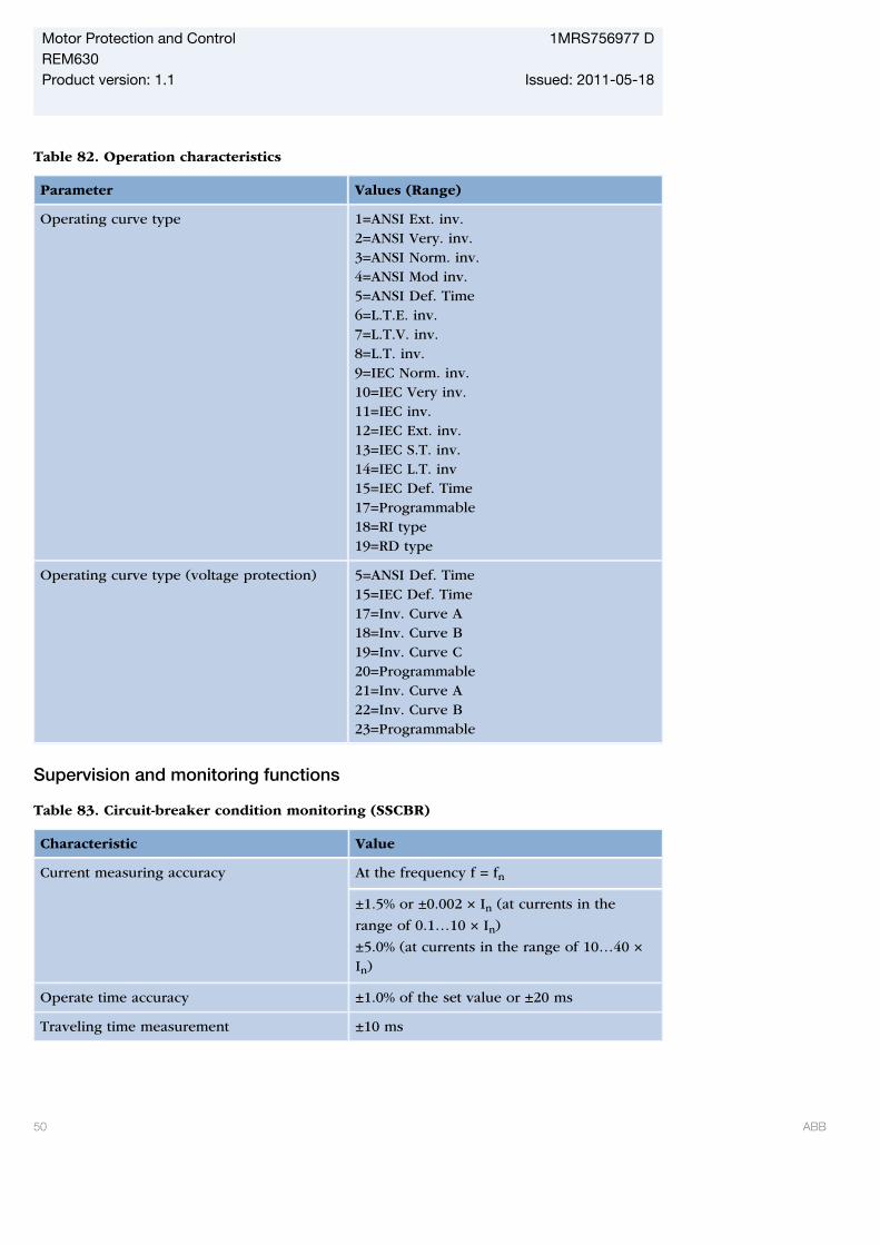
Table 82. Operation characteristics
Parameter Values (Range)
Operating curve type 1=ANSI Ext. inv.2=ANSI Very. inv.3=ANSI Norm. inv.4=ANSI Mod inv.5=ANSI Def. Time6=L.T.E. inv.7=L.T.V. inv.8=L.T. inv.9=IEC Norm. inv.10=IEC Very inv.11=IEC inv.12=IEC Ext. inv.13=IEC S.T. inv.14=IEC L.T. inv15=IEC Def. Time17=Programmable18=RI type19=RD type
Operating curve type (voltage protection) 5=ANSI Def. Time15=IEC Def. Time17=Inv. Curve A18=Inv. Curve B19=Inv. Curve C20=Programmable21=Inv. Curve A22=Inv. Curve B23=Programmable
Supervision and monitoring functions
Table 83. Circuit-breaker condition monitoring (SSCBR)
Characteristic Value
Current measuring accuracy At the frequency f = fn
±1.5% or ±0.002 × In (at currents in the
range of 0.1…10 × In)
±5.0% (at currents in the range of 10…40 ×In)
Operate time accuracy ±1.0% of the set value or ±20 ms
Traveling time measurement ±10 ms
Motor Protection and Control 1MRS756977 DREM630Product version: 1.1 Issued: 2011-05-18
50 ABB
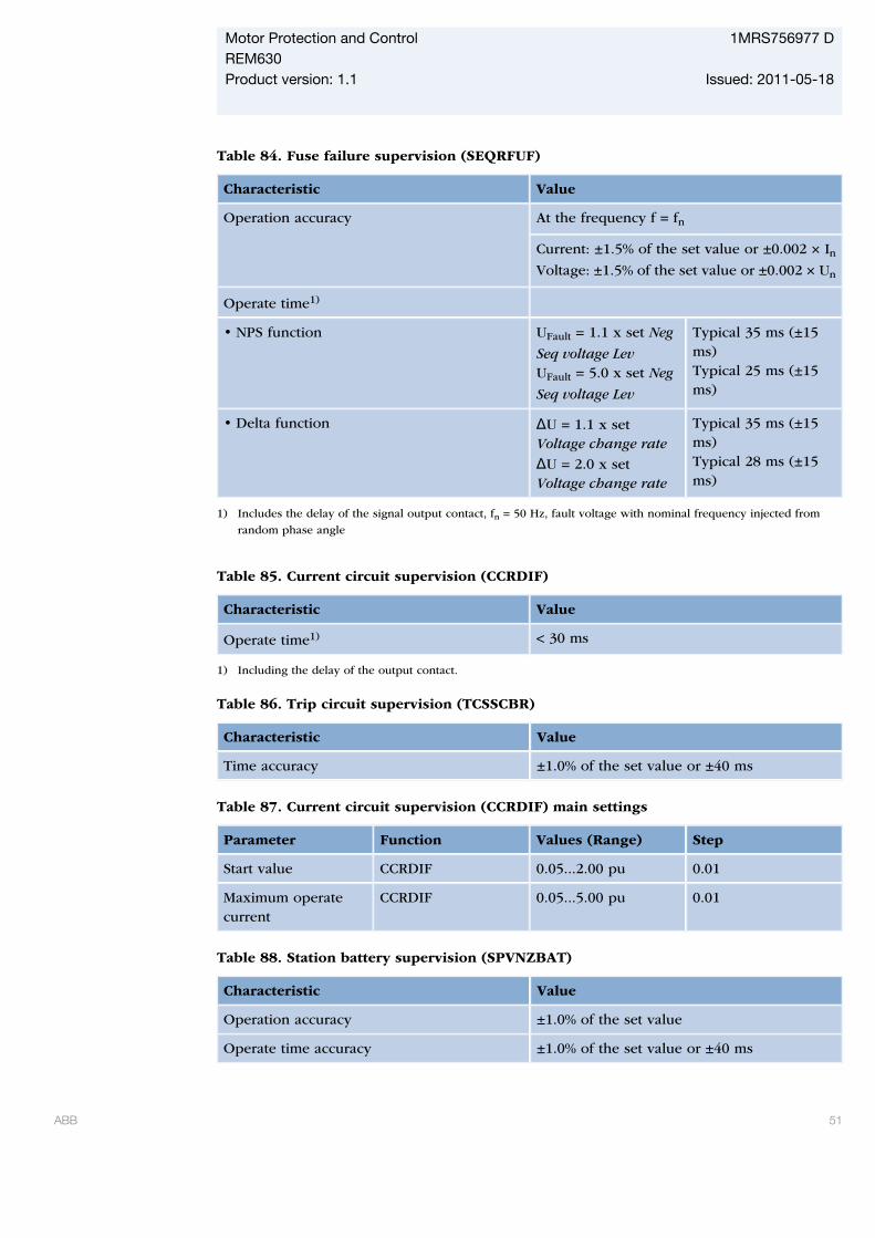
Table 84. Fuse failure supervision (SEQRFUF)
Characteristic Value
Operation accuracy At the frequency f = fn
Current: ±1.5% of the set value or ±0.002 × InVoltage: ±1.5% of the set value or ±0.002 × Un
Operate time1)
• NPS function UFault = 1.1 x set Neg
Seq voltage LevUFault = 5.0 x set Neg
Seq voltage Lev
Typical 35 ms (±15ms)Typical 25 ms (±15ms)
• Delta function ΔU = 1.1 x setVoltage change rate
ΔU = 2.0 x setVoltage change rate
Typical 35 ms (±15ms)Typical 28 ms (±15ms)
1) Includes the delay of the signal output contact, fn = 50 Hz, fault voltage with nominal frequency injected from
random phase angle
Table 85. Current circuit supervision (CCRDIF)
Characteristic Value
Operate time1) < 30 ms
1) Including the delay of the output contact.
Table 86. Trip circuit supervision (TCSSCBR)
Characteristic Value
Time accuracy ±1.0% of the set value or ±40 ms
Table 87. Current circuit supervision (CCRDIF) main settings
Parameter Function Values (Range) Step
Start value CCRDIF 0.05...2.00 pu 0.01
Maximum operatecurrent
CCRDIF 0.05...5.00 pu 0.01
Table 88. Station battery supervision (SPVNZBAT)
Characteristic Value
Operation accuracy ±1.0% of the set value
Operate time accuracy ±1.0% of the set value or ±40 ms
Motor Protection and Control 1MRS756977 DREM630Product version: 1.1 Issued: 2011-05-18
ABB 51
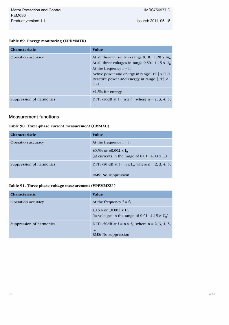
Table 89. Energy monitoring (EPDMMTR)
Characteristic Value
Operation accuracy At all three currents in range 0.10…1.20 x Inn
At all three voltages in range 0.50…1.15 x Un
At the frequency f = fnActive power and energy in range |PF| > 0.71Reactive power and energy in range |PF| <0.71
±1.5% for energy
Suppression of harmonics DFT: -50dB at f = n x fn, where n = 2, 3, 4, 5,
…
Measurement functions
Table 90. Three-phase current measurement (CMMXU)
Characteristic Value
Operation accuracy At the frequency f = fn
±0.5% or ±0.002 x In(at currents in the range of 0.01...4.00 x In)
Suppression of harmonics DFT: -50 dB at f = n x fn, where n = 2, 3, 4, 5,
…RMS: No suppression
Table 91. Three-phase voltage measurement (VPPMMXU )
Characteristic Value
Operation accuracy At the frequency f = fn
±0.5% or ±0.002 x Un
(at voltages in the range of 0.01...1.15 × Un)
Suppression of harmonics DFT: -50dB at f = n × fn, where n = 2, 3, 4, 5,
…RMS: No suppression
Motor Protection and Control 1MRS756977 DREM630Product version: 1.1 Issued: 2011-05-18
52 ABB
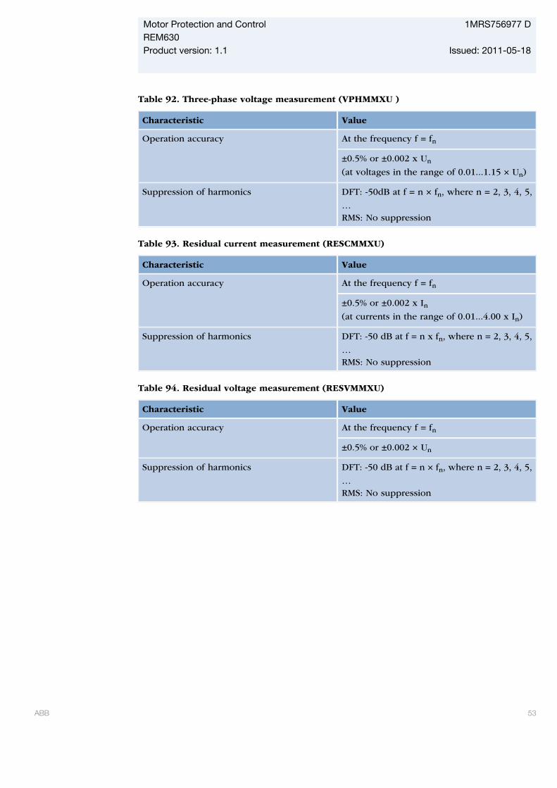
Table 92. Three-phase voltage measurement (VPHMMXU )
Characteristic Value
Operation accuracy At the frequency f = fn
±0.5% or ±0.002 x Un
(at voltages in the range of 0.01...1.15 × Un)
Suppression of harmonics DFT: -50dB at f = n × fn, where n = 2, 3, 4, 5,
…RMS: No suppression
Table 93. Residual current measurement (RESCMMXU)
Characteristic Value
Operation accuracy At the frequency f = fn
±0.5% or ±0.002 x In(at currents in the range of 0.01...4.00 x In)
Suppression of harmonics DFT: -50 dB at f = n x fn, where n = 2, 3, 4, 5,
…RMS: No suppression
Table 94. Residual voltage measurement (RESVMMXU)
Characteristic Value
Operation accuracy At the frequency f = fn
±0.5% or ±0.002 × Un
Suppression of harmonics DFT: -50 dB at f = n × fn, where n = 2, 3, 4, 5,
…RMS: No suppression
Motor Protection and Control 1MRS756977 DREM630Product version: 1.1 Issued: 2011-05-18
ABB 53
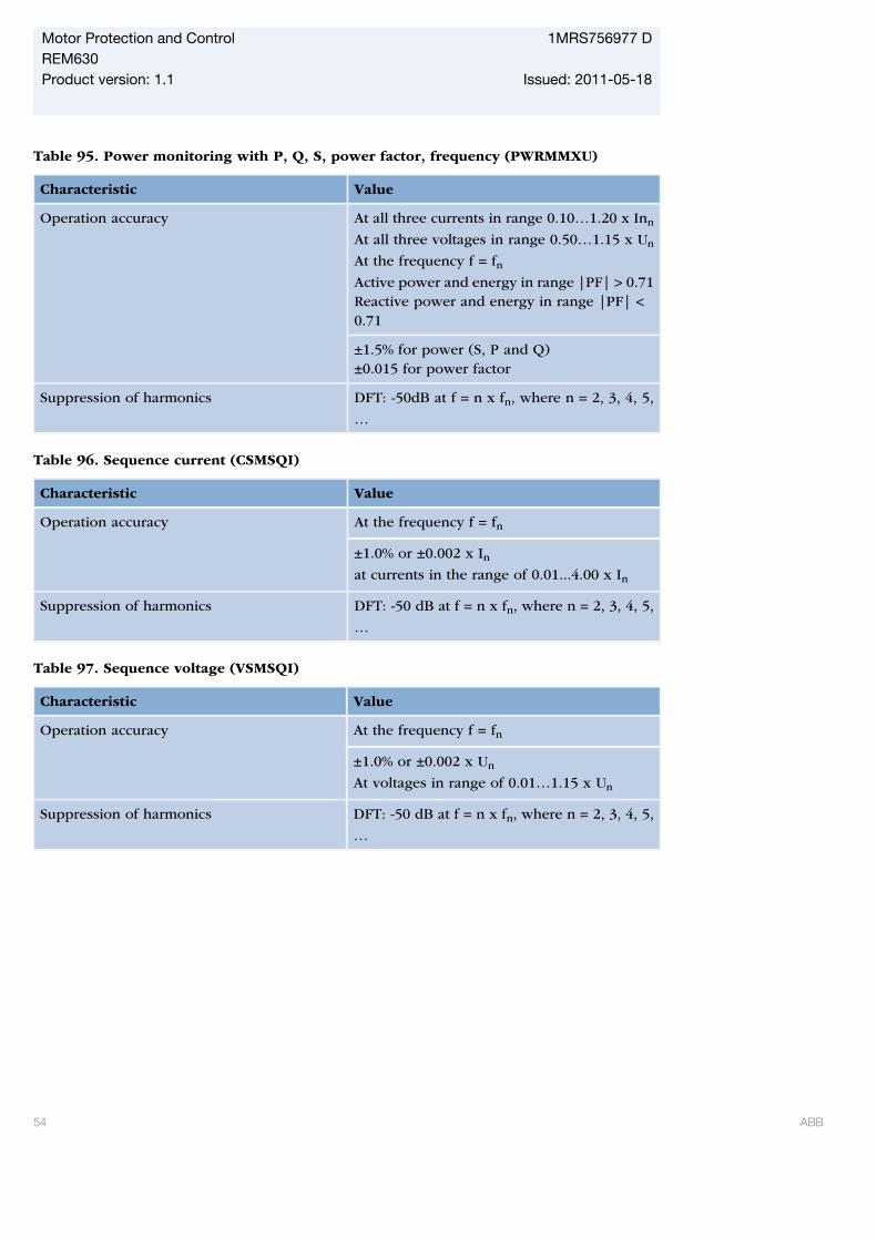
Table 95. Power monitoring with P, Q, S, power factor, frequency (PWRMMXU)
Characteristic Value
Operation accuracy At all three currents in range 0.10…1.20 x Inn
At all three voltages in range 0.50…1.15 x Un
At the frequency f = fnActive power and energy in range |PF| > 0.71Reactive power and energy in range |PF| <0.71
±1.5% for power (S, P and Q)±0.015 for power factor
Suppression of harmonics DFT: -50dB at f = n x fn, where n = 2, 3, 4, 5,
…
Table 96. Sequence current (CSMSQI)
Characteristic Value
Operation accuracy At the frequency f = fn
±1.0% or ±0.002 x Inat currents in the range of 0.01...4.00 x In
Suppression of harmonics DFT: -50 dB at f = n x fn, where n = 2, 3, 4, 5,
…
Table 97. Sequence voltage (VSMSQI)
Characteristic Value
Operation accuracy At the frequency f = fn
±1.0% or ±0.002 x Un
At voltages in range of 0.01…1.15 x Un
Suppression of harmonics DFT: -50 dB at f = n x fn, where n = 2, 3, 4, 5,
…
Motor Protection and Control 1MRS756977 DREM630Product version: 1.1 Issued: 2011-05-18
54 ABB
19. Front panel userinterface
The 630 series IEDs can be ordered with andetached front-panel user interface (HMI). Anintegrated HMI is available for 4U highhousing. The local HMI includes a largegraphical monochrome LCD with a resolutionof 320 x 240 pixels (width x height). Theamount of characters and rows fitting theview depends on the character size as thecharacters' width and height may vary.
In addition, the local HMI includes dedicatedopen/close operating buttons and five
programmable function buttons with LEDindicators. The 15 programmable alarm LEDscan indicate a total of 45 alarms. The localHMI offers full front-panel user-interfacefunctionality with menu navigation, menuviews and operational data. In addition, thelocal HMI can, using PCM600, be configuredto show a single-line diagram (SLD). The SLDview displays the status of the primaryapparatus such as circuit breakers anddisconnectors, selected measurement valuesand busbar arrangements.
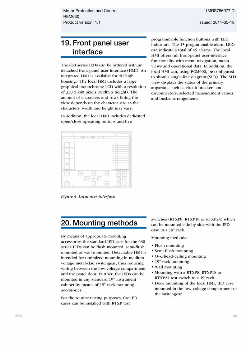
GUID-5CFD3446-A92F-4A5F-B60D-90025DCFDC61 V2 EN
Figure 4. Local user interface
20. Mounting methods
By means of appropriate mountingaccessories the standard IED case for the 630series IEDs can be flush mounted, semi-flushmounted or wall mounted. Detachable HMI isintended for optimized mounting in mediumvoltage metal-clad switchgear, thus reducingwiring between the low-voltage compartmentand the panel door. Further, the IEDs can bemounted in any standard 19” instrumentcabinet by means of 19” rack mountingaccessories.
For the routine testing purposes, the IEDcases can be installed with RTXP test
switches (RTXP8, RTXP18 or RTXP24) whichcan be mounted side by side with the IEDcase in a 19” rack.
Mounting methods:
• Flush mounting• Semi-flush mounting• Overhead/ceiling mounting• 19” rack mounting• Wall mounting• Mounting with a RTXP8, RTXP18 or
RTXP24 test switch to a 19”rack• Door mounting of the local HMI, IED case
mounted in the low-voltage compartment ofthe switchgear
Motor Protection and Control 1MRS756977 DREM630Product version: 1.1 Issued: 2011-05-18
ABB 55
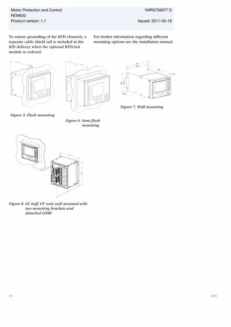
To ensure grounding of the RTD channels, aseparate cable shield rail is included in theIED delivery when the optional RTD/mAmodule is ordered.
For further information regarding differentmounting options see the installation manual.
GUID-8E2EDADD-D709-423D-8677-E3CF75DB256F V1 EN
Figure 5. Flush mounting GUID-AF1BEC0B-A9DC-4E9B-9C89-98F28B1C81DB V1 EN
Figure 6. Semi-flushmounting
252,5
270
ø6,8
180
101,6
13
366
GUID-945D3C86-A432-4C1F-927A-A208E0C1F5F6 V2 EN
Figure 7. Wall mounting
224
265,9
22025,5
177 258,6
13
GUID-A368C5C3-D4A9-40B7-BD0E-181A6BB7ECA6 V1 EN
Figure 8. 6U half 19" unit wall mounted withtwo mounting brackets anddetached LHMI
Motor Protection and Control 1MRS756977 DREM630Product version: 1.1 Issued: 2011-05-18
56 ABB
21. Selection andordering data
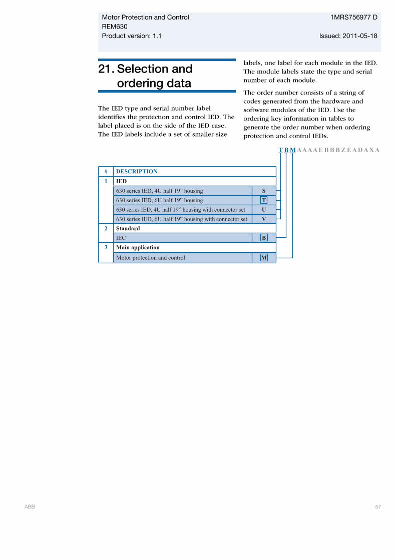
The IED type and serial number labelidentifies the protection and control IED. Thelabel placed is on the side of the IED case.The IED labels include a set of smaller size
labels, one label for each module in the IED.The module labels state the type and serialnumber of each module.
The order number consists of a string ofcodes generated from the hardware andsoftware modules of the IED. Use theordering key information in tables togenerate the order number when orderingprotection and control IEDs.
T B M A A A A E B B B Z E A D A X A
# DESCRIPTION1 IED
630 series IED, 4U half 19” housing S630 series IED, 6U half 19” housing T630 series IED, 4U half 19” housing with connector set U630 series IED, 6U half 19” housing with connector set V
2 StandardIEC B
3 Main application
Motor protection and control MGUID-408849B5-009B-464A-B683-6A82BB780417 V2 EN
Motor Protection and Control 1MRS756977 DREM630Product version: 1.1 Issued: 2011-05-18
ABB 57
-
T B M A A A A E B B B Z E A D A X B
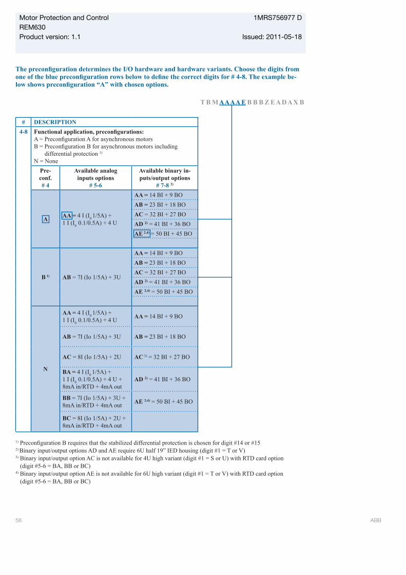
# DESCRIPTION4-8
differential protection 1)
N = NonePre- conf.# 4
Available analog inputs options
# 5-6
Available binary in-puts/output options
# 7-8 2)
A AA = 4 I (I0 1/5A) + 1 I (I0 0.1/0.5A) + 4 U
AA = 14 BI + 9 BOAB = 23 BI + 18 BOAC = 32 BI + 27 BOAD 2) = 41 BI + 36 BOAE 2,4) = 50 BI + 45 BO
B 1) AB = 7I (Io 1/5A) + 3U
AA = 14 BI + 9 BOAB = 23 BI + 18 BOAC = 32 BI + 27 BOAD 2) = 41 BI + 36 BOAE 2,4) = 50 BI + 45 BO
N
AA = 4 I (I0 1/5A) + 1 I (I0 0.1/0.5A) + 4 U AA = 14 BI + 9 BO
AB = 7I (Io 1/5A) + 3U AB = 23 BI + 18 BO
AC = 8I (Io 1/5A) + 2U AC 3) = 32 BI + 27 BO
BA = 4 I (I0 1/5A) + 1 I (I0 0.1/0.5A) + 4 U + 8mA in/RTD + 4mA out
AD 2) = 41 BI + 36 BO
BB = 7I (Io 1/5A) + 3U + 8mA in/RTD + 4mA out AE 2,4) = 50 BI + 45 BO
BC = 8I (Io 1/5A) + 2U + 8mA in/RTD + 4mA out
1)
2) Binary input/output options AD and AE require 6U half 19” IED housing (digit #1 = T or V)3) Binary input/output option AC is not available for 4U high variant (digit #1 = S or U) with RTD card option (digit #5-6 = BA, BB or BC)4) Binary input/output option AE is not available for 6U high variant (digit #1 = T or V) with RTD card option (digit #5-6 = BA, BB or BC)
GUID-20C7D93F-1F44-47E2-80EF-CBCAC314C85A V2 EN
Motor Protection and Control 1MRS756977 DREM630Product version: 1.1 Issued: 2011-05-18
58 ABB
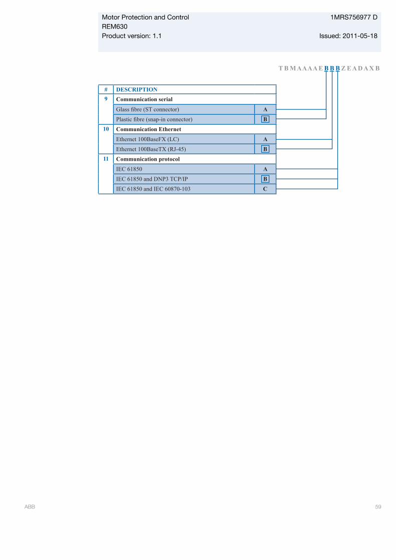
T B M A A A A E B B B Z E A D A X B
# DESCRIPTION 9 Communication serial
A
B10 Communication Ethernet
Ethernet 100BaseFX (LC) A
Ethernet 100BaseTX (RJ-45) B11 Communication protocol
IEC 61850 A
IEC 61850 and DNP3 TCP/IP B
IEC 61850 and IEC 60870-103 CGUID-EECA92DD-3431-4F66-A1BC-18ACE2E27145 V2 EN
Motor Protection and Control 1MRS756977 DREM630Product version: 1.1 Issued: 2011-05-18
ABB 59
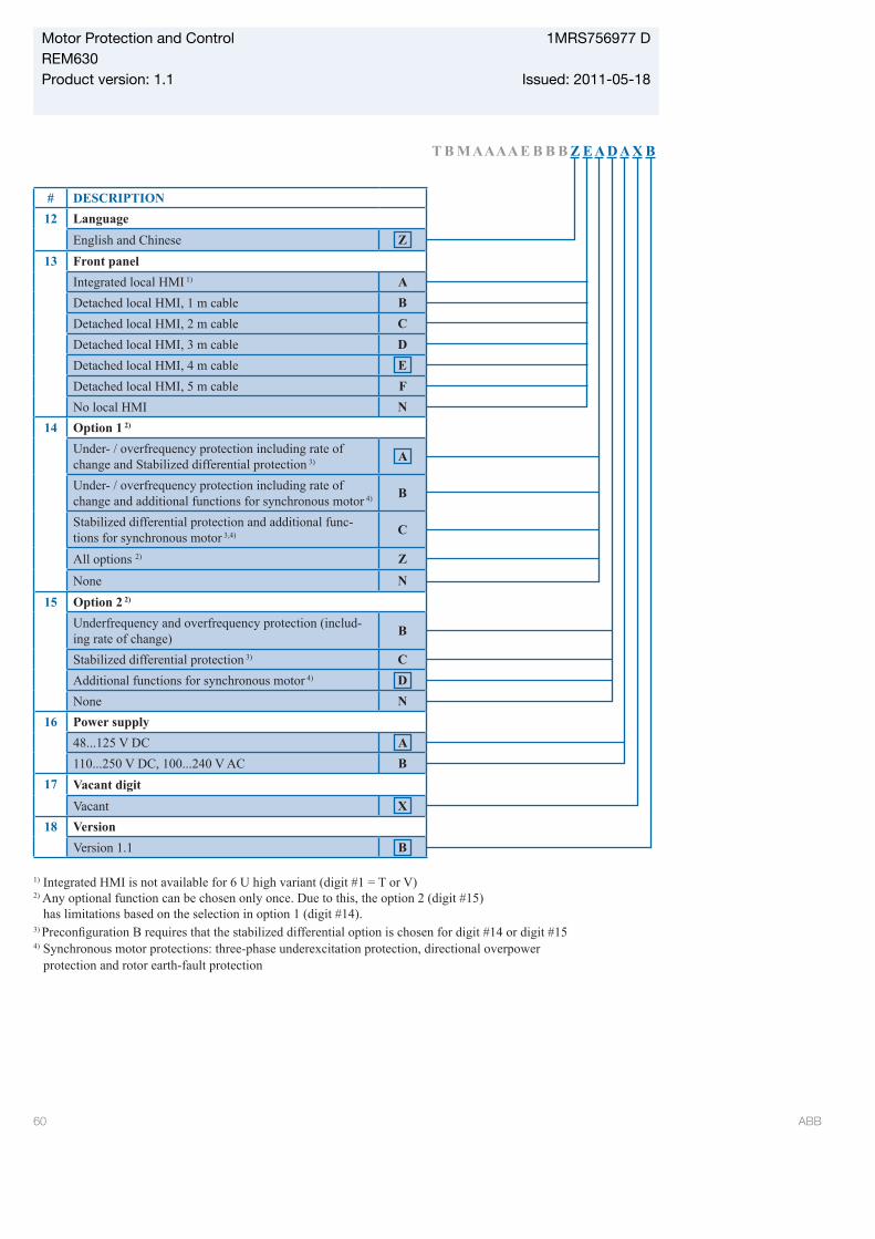
T B M A A A A E B B B Z E A D A X B
# DESCRIPTION12 Language
English and Chinese Z13 Front panel
Integrated local HMI 1) ADetached local HMI, 1 m cable BDetached local HMI, 2 m cable CDetached local HMI, 3 m cable DDetached local HMI, 4 m cable EDetached local HMI, 5 m cable FNo local HMI N
14 Option 1 2)
Under- / overfrequency protection including rate of change and Stabilized differential protection 3) A
Under- / overfrequency protection including rate of change and additional functions for synchronous motor 4) B
Stabilized differential protection and additional func-tions for synchronous motor 3,4) C
All options 2) Z
None N15 Option 2 2)
Underfrequency and overfrequency protection (includ-ing rate of change) B
Stabilized differential protection 3) CAdditional functions for synchronous motor 4) DNone N
16 Power supply48...125 V DC A110...250 V DC, 100...240 V AC B
17 Vacant digitVacant X
18 VersionVersion 1.1 B
1) Integrated HMI is not available for 6 U high variant (digit #1 = T or V)2) Any optional function can be chosen only once. Due to this, the option 2 (digit #15) has limitations based on the selection in option 1 (digit #14).3)
4) Synchronous motor protections: three-phase underexcitation protection, directional overpower protection and rotor earth-fault protection
GUID-CCBE04DE-AF7C-4B3F-A65D-F28187797F7B V2 EN
Motor Protection and Control 1MRS756977 DREM630Product version: 1.1 Issued: 2011-05-18
60 ABB
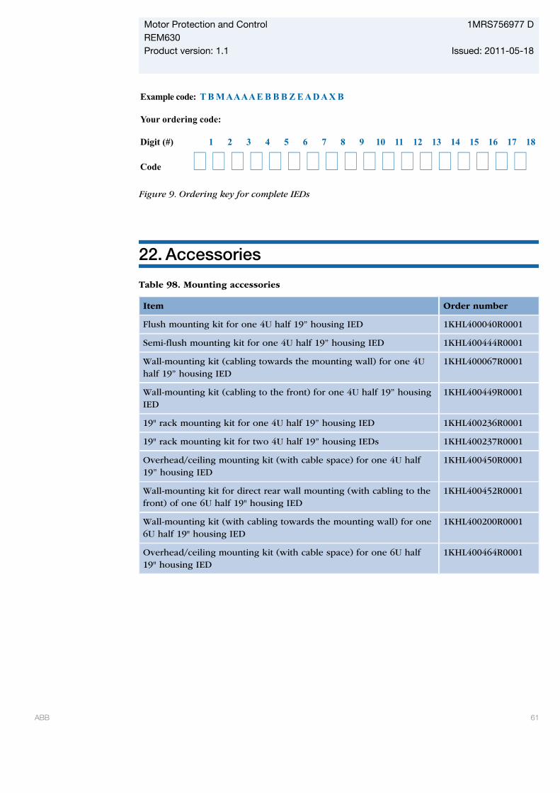
Example code: T B M A A A A E B B B Z E A D A X B
Your ordering code:
Digit (#) 1 2 3 4 5 6 7 8 9 10 11 12 13 14 15 16 17 18
Code GUID-34B7648F-E4A4-4201-8273-079E18139838 V2 EN
Figure 9. Ordering key for complete IEDs
22. Accessories
Table 98. Mounting accessories
Item Order number
Flush mounting kit for one 4U half 19” housing IED 1KHL400040R0001
Semi-flush mounting kit for one 4U half 19” housing IED 1KHL400444R0001
Wall-mounting kit (cabling towards the mounting wall) for one 4Uhalf 19” housing IED
1KHL400067R0001
Wall-mounting kit (cabling to the front) for one 4U half 19” housingIED
1KHL400449R0001
19" rack mounting kit for one 4U half 19” housing IED 1KHL400236R0001
19" rack mounting kit for two 4U half 19” housing IEDs 1KHL400237R0001
Overhead/ceiling mounting kit (with cable space) for one 4U half19” housing IED
1KHL400450R0001
Wall-mounting kit for direct rear wall mounting (with cabling to thefront) of one 6U half 19" housing IED
1KHL400452R0001
Wall-mounting kit (with cabling towards the mounting wall) for one6U half 19" housing IED
1KHL400200R0001
Overhead/ceiling mounting kit (with cable space) for one 6U half19" housing IED
1KHL400464R0001
Motor Protection and Control 1MRS756977 DREM630Product version: 1.1 Issued: 2011-05-18
ABB 61
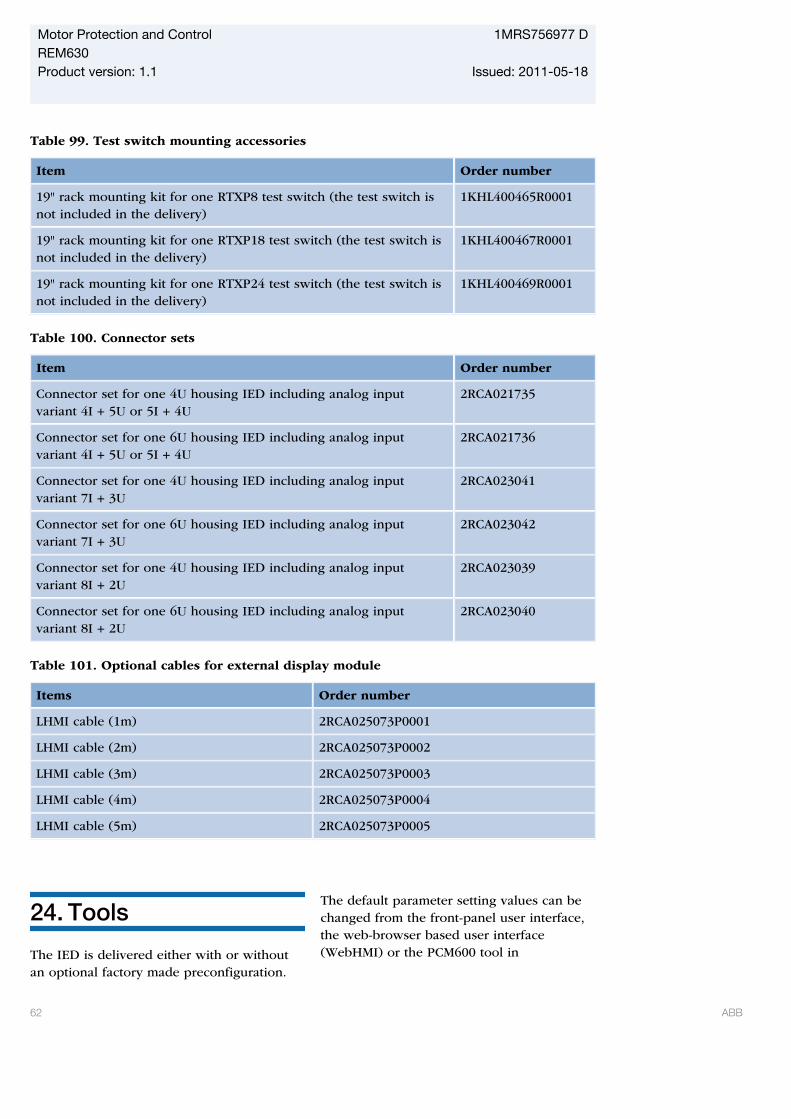
Table 99. Test switch mounting accessories
Item Order number
19" rack mounting kit for one RTXP8 test switch (the test switch isnot included in the delivery)
1KHL400465R0001
19" rack mounting kit for one RTXP18 test switch (the test switch isnot included in the delivery)
1KHL400467R0001
19" rack mounting kit for one RTXP24 test switch (the test switch isnot included in the delivery)
1KHL400469R0001
Table 100. Connector sets
Item Order number
Connector set for one 4U housing IED including analog inputvariant 4I + 5U or 5I + 4U
2RCA021735
Connector set for one 6U housing IED including analog inputvariant 4I + 5U or 5I + 4U
2RCA021736
Connector set for one 4U housing IED including analog inputvariant 7I + 3U
2RCA023041
Connector set for one 6U housing IED including analog inputvariant 7I + 3U
2RCA023042
Connector set for one 4U housing IED including analog inputvariant 8I + 2U
2RCA023039
Connector set for one 6U housing IED including analog inputvariant 8I + 2U
2RCA023040
Table 101. Optional cables for external display module
Items Order number
LHMI cable (1m) 2RCA025073P0001
LHMI cable (2m) 2RCA025073P0002
LHMI cable (3m) 2RCA025073P0003
LHMI cable (4m) 2RCA025073P0004
LHMI cable (5m) 2RCA025073P0005
24. Tools
The IED is delivered either with or withoutan optional factory made preconfiguration.
The default parameter setting values can bechanged from the front-panel user interface,the web-browser based user interface(WebHMI) or the PCM600 tool in
Motor Protection and Control 1MRS756977 DREM630Product version: 1.1 Issued: 2011-05-18
62 ABB
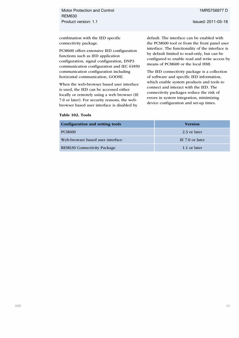
combination with the IED specificconnectivity package.
PCM600 offers extensive IED configurationfunctions such as IED applicationconfiguration, signal configuration, DNP3communication configuration and IEC 61850communication configuration includinghorizontal communication, GOOSE.
When the web-browser based user interfaceis used, the IED can be accessed eitherlocally or remotely using a web browser (IE7.0 or later). For security reasons, the web-browser based user interface is disabled by
default. The interface can be enabled withthe PCM600 tool or from the front panel userinterface. The functionality of the interface isby default limited to read-only, but can beconfigured to enable read and write access bymeans of PCM600 or the local HMI.
The IED connectivity package is a collectionof software and specific IED information,which enable system products and tools toconnect and interact with the IED. Theconnectivity packages reduce the risk oferrors in system integration, minimizingdevice configuration and set-up times.
Table 102. Tools
Configuration and setting tools Version
PCM600 2.3 or later
Web-browser based user interface IE 7.0 or later
REM630 Connectivity Package 1.1 or later
Motor Protection and Control 1MRS756977 DREM630Product version: 1.1 Issued: 2011-05-18
ABB 63
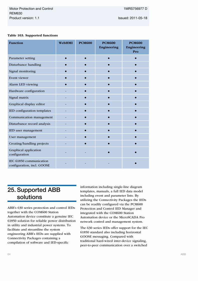
Table 103. Supported functions
Function WebHMI PCM600 PCM600Engineering
PCM600Engineering
Pro
Parameter setting
Disturbance handling
Signal monitoring
Event viewer
Alarm LED viewing
Hardware configuration -
Signal matrix -
Graphical display editor -
IED configuration templates -
Communication management -
Disturbance record analysis -
IED user management -
User management -
Creating/handling projects -
Graphical applicationconfiguration
- -
IEC 61850 communicationconfiguration, incl. GOOSE
- - -
25. Supported ABBsolutions
ABB’s 630 series protection and control IEDstogether with the COM600 StationAutomation device constitute a genuine IEC61850 solution for reliable power distributionin utility and industrial power systems. Tofacilitate and streamline the systemengineering ABB’s IEDs are supplied withConnectivity Packages containing acompilation of software and IED-specific
information including single-line diagramtemplates, manuals, a full IED data modelincluding event and parameter lists. Byutilizing the Connectivity Packages the IEDscan be readily configured via the PCM600Protection and Control IED Manager andintegrated with the COM600 StationAutomation device or the MicroSCADA Pronetwork control and management system.
The 630 series IEDs offer support for the IEC61850 standard also including horizontalGOOSE messaging. Compared withtraditional hard-wired inter-device signaling,peer-to-peer communication over a switched
Motor Protection and Control 1MRS756977 DREM630Product version: 1.1 Issued: 2011-05-18
64 ABB
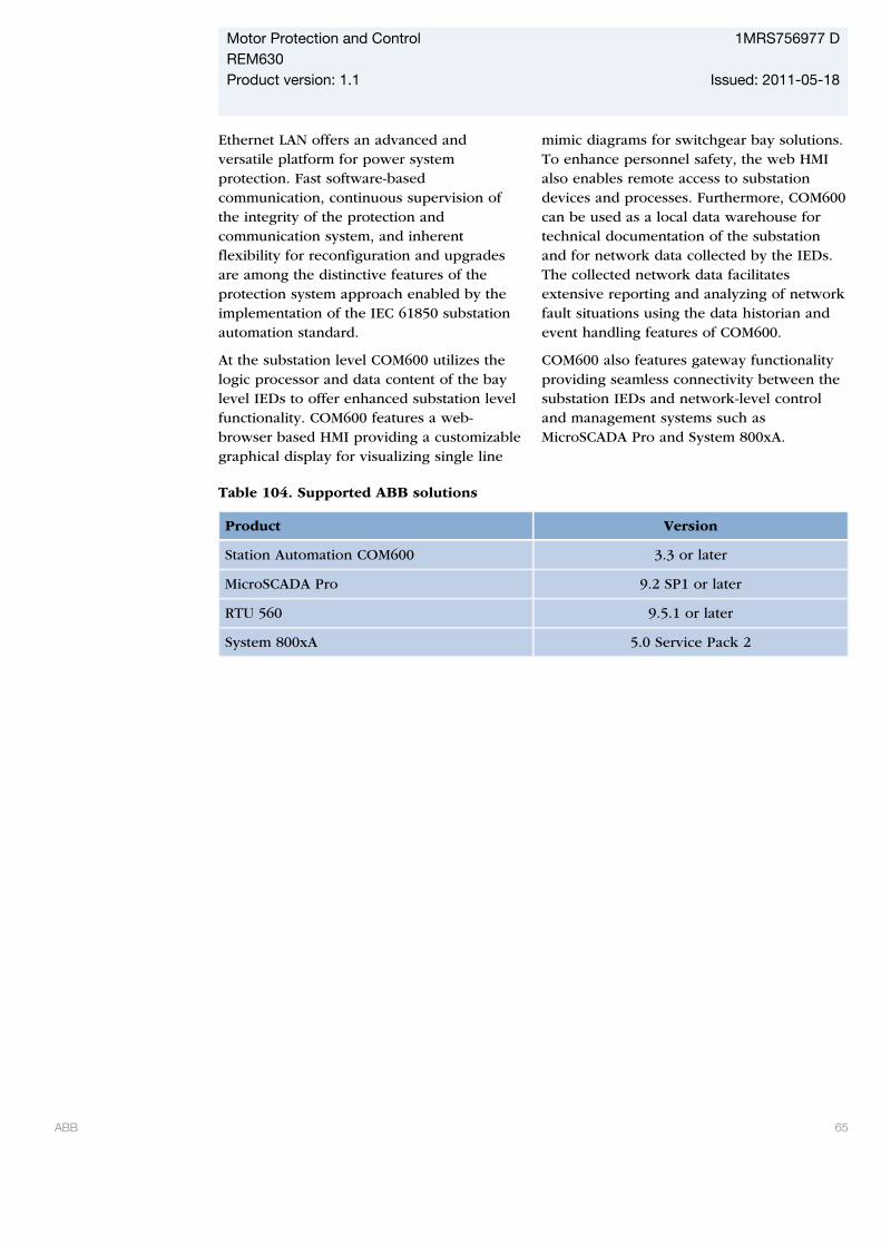
Ethernet LAN offers an advanced andversatile platform for power systemprotection. Fast software-basedcommunication, continuous supervision ofthe integrity of the protection andcommunication system, and inherentflexibility for reconfiguration and upgradesare among the distinctive features of theprotection system approach enabled by theimplementation of the IEC 61850 substationautomation standard.
At the substation level COM600 utilizes thelogic processor and data content of the baylevel IEDs to offer enhanced substation levelfunctionality. COM600 features a web-browser based HMI providing a customizablegraphical display for visualizing single line
mimic diagrams for switchgear bay solutions.To enhance personnel safety, the web HMIalso enables remote access to substationdevices and processes. Furthermore, COM600can be used as a local data warehouse fortechnical documentation of the substationand for network data collected by the IEDs.The collected network data facilitatesextensive reporting and analyzing of networkfault situations using the data historian andevent handling features of COM600.
COM600 also features gateway functionalityproviding seamless connectivity between thesubstation IEDs and network-level controland management systems such asMicroSCADA Pro and System 800xA.
Table 104. Supported ABB solutions
Product Version
Station Automation COM600 3.3 or later
MicroSCADA Pro 9.2 SP1 or later
RTU 560 9.5.1 or later
System 800xA 5.0 Service Pack 2
Motor Protection and Control 1MRS756977 DREM630Product version: 1.1 Issued: 2011-05-18
ABB 65

26. Terminal diagrams
GUID-28C73256-8E73-434F-BA71-FE0AF16DBA64 V1 EN
Figure 10. Terminal diagram for REM630
Motor Protection and Control 1MRS756977 DREM630Product version: 1.1 Issued: 2011-05-18
66 ABB
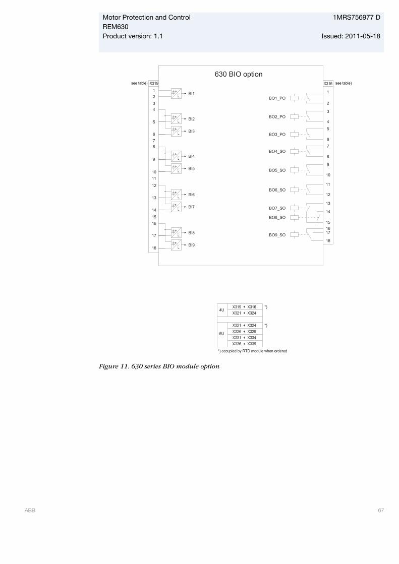
GUID-5E27DD50-FD15-4824-BDFB-DD52E29730EA V1 EN
Figure 11. 630 series BIO module option
Motor Protection and Control 1MRS756977 DREM630Product version: 1.1 Issued: 2011-05-18
ABB 67
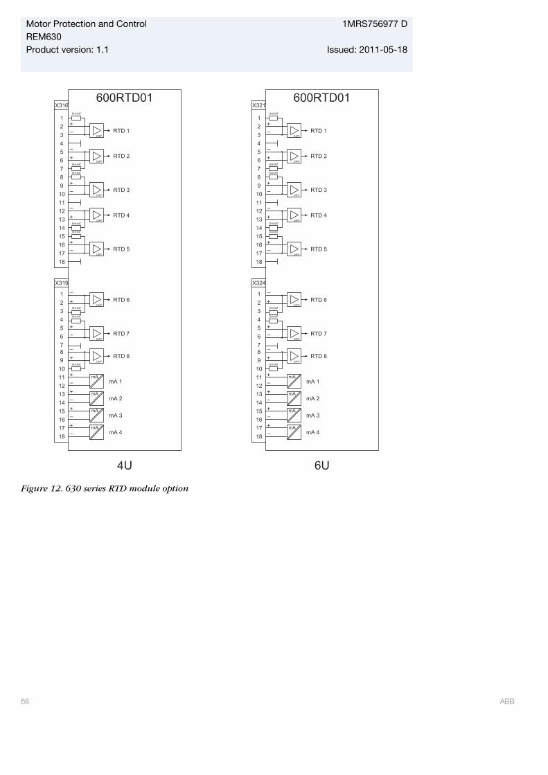
GUID-CB7B1CF8-A0E4-42F5-998C-701641515127 V1 EN
Figure 12. 630 series RTD module option
Motor Protection and Control 1MRS756977 DREM630Product version: 1.1 Issued: 2011-05-18
68 ABB
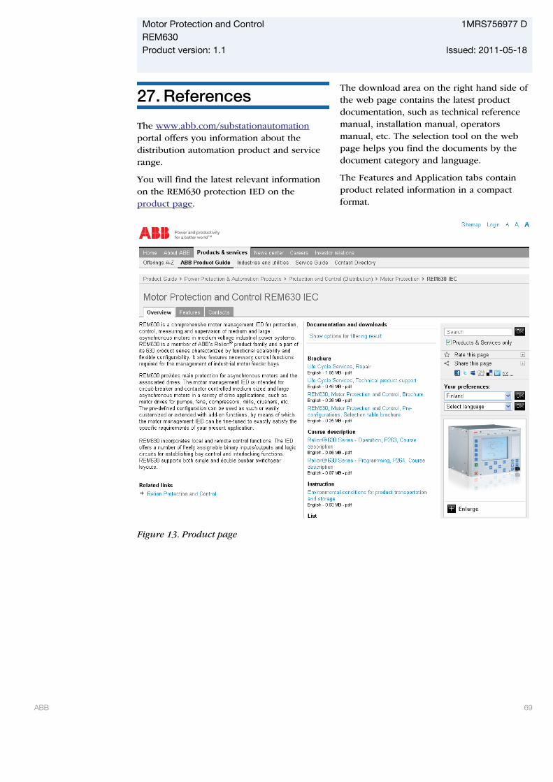
27. References
The www.abb.com/substationautomationportal offers you information about thedistribution automation product and servicerange.
You will find the latest relevant informationon the REM630 protection IED on theproduct page.
The download area on the right hand side ofthe web page contains the latest productdocumentation, such as technical referencemanual, installation manual, operatorsmanual, etc. The selection tool on the webpage helps you find the documents by thedocument category and language.
The Features and Application tabs containproduct related information in a compactformat.
GUID-3E17F899-5BED-425E-8639-EBD340DE353D V1 EN
Figure 13. Product page
Motor Protection and Control 1MRS756977 DREM630Product version: 1.1 Issued: 2011-05-18
ABB 69
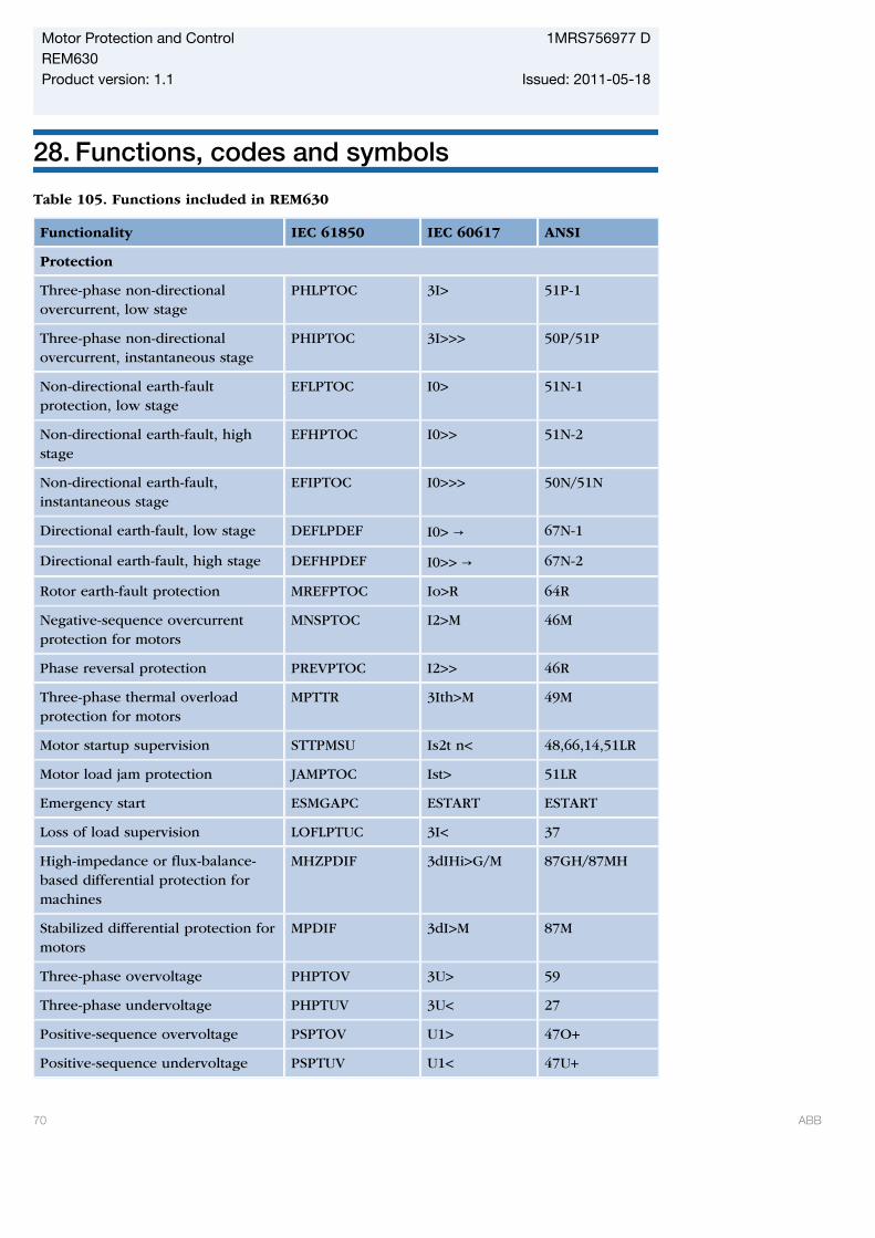
28. Functions, codes and symbols
Table 105. Functions included in REM630
Functionality IEC 61850 IEC 60617 ANSI
Protection
Three-phase non-directionalovercurrent, low stage
PHLPTOC 3I> 51P-1
Three-phase non-directionalovercurrent, instantaneous stage
PHIPTOC 3I>>> 50P/51P
Non-directional earth-faultprotection, low stage
EFLPTOC I0> 51N-1
Non-directional earth-fault, highstage
EFHPTOC I0>> 51N-2
Non-directional earth-fault,instantaneous stage
EFIPTOC I0>>> 50N/51N
Directional earth-fault, low stage DEFLPDEF I0> → 67N-1
Directional earth-fault, high stage DEFHPDEF I0>> → 67N-2
Rotor earth-fault protection MREFPTOC Io>R 64R
Negative-sequence overcurrentprotection for motors
MNSPTOC I2>M 46M
Phase reversal protection PREVPTOC I2>> 46R
Three-phase thermal overloadprotection for motors
MPTTR 3Ith>M 49M
Motor startup supervision STTPMSU Is2t n< 48,66,14,51LR
Motor load jam protection JAMPTOC Ist> 51LR
Emergency start ESMGAPC ESTART ESTART
Loss of load supervision LOFLPTUC 3I< 37
High-impedance or flux-balance-based differential protection formachines
MHZPDIF 3dIHi>G/M 87GH/87MH
Stabilized differential protection formotors
MPDIF 3dI>M 87M
Three-phase overvoltage PHPTOV 3U> 59
Three-phase undervoltage PHPTUV 3U< 27
Positive-sequence overvoltage PSPTOV U1> 47O+
Positive-sequence undervoltage PSPTUV U1< 47U+
Motor Protection and Control 1MRS756977 DREM630Product version: 1.1 Issued: 2011-05-18
70 ABB
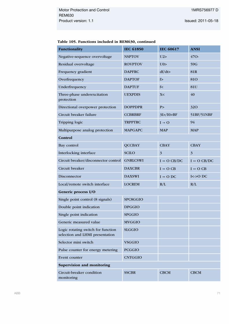
Table 105. Functions included in REM630, continued
Functionality IEC 61850 IEC 60617 ANSI
Negative-sequence overvoltage NSPTOV U2> 47O-
Residual overvoltage ROVPTOV U0> 59G
Frequency gradient DAPFRC df/dt> 81R
Overfrequency DAPTOF f> 81O
Underfrequency DAPTUF f< 81U
Three-phase underexcitationprotection
UEXPDIS X< 40
Directional overpower protection DOPPDPR P> 32O
Circuit breaker failure CCBRBRF 3I>/I0>BF 51BF/51NBF
Tripping logic TRPPTRC I → O 94
Multipurpose analog protection MAPGAPC MAP MAP
Control
Bay control QCCBAY CBAY CBAY
Interlocking interface SCILO 3 3
Circuit breaker/disconnector control GNRLCSWI I ↔ O CB/DC I ↔ O CB/DC
Circuit breaker DAXCBR I ↔ O CB I ↔ O CB
Disconnector DAXSWI I ↔ O DC I<->O DC
Local/remote switch interface LOCREM R/L R/L
Generic process I/O
Single point control (8 signals) SPC8GGIO
Double point indication DPGGIO
Single point indication SPGGIO
Generic measured value MVGGIO
Logic rotating switch for functionselection and LHMI presentation
SLGGIO
Selector mini switch VSGGIO
Pulse counter for energy metering PCGGIO
Event counter CNTGGIO
Supervision and monitoring
Circuit-breaker conditionmonitoring
SSCBR CBCM CBCM
Motor Protection and Control 1MRS756977 DREM630Product version: 1.1 Issued: 2011-05-18
ABB 71

Table 105. Functions included in REM630, continued
Functionality IEC 61850 IEC 60617 ANSI
Fuse failure supervision SEQRFUF FUSEF 60
Current circuit supervision CCRDIF MCS 3I MCS 3I
Trip circuit supervision TCSSCBR TCS TCM
Station battery supervision SPVNZBAT U<> U<>
Energy monitoring EPDMMTR E E
Measured value limit supervision MVEXP
Measurement
Three-phase current CMMXU 3I 3I
Three-phase voltage (phase-to-earth)
VPHMMXU 3Upe 3Upe
Three phase voltage (phase-to-phase)
VPPMMXU 3Upp 3Upp
Residual current RESCMMXU I0 I0
Residual voltage RESVMMXU U0 Vn
Sequence current CSMSQI I1, I2 I1, I2
Sequence voltage VSMSQI U1, U2 V1, V2
Power monitoring with P, Q, S,power factor, frequency
PWRMMXU PQf PQf
Disturbance recorder function
Analog channels 1-10 (samples) A1RADR ACH1 ACH1
Analog channels 11-20 (samples) A2RADR ACH2 ACH2
Analog channels 21-30 (calc. val.) A3RADR ACH3 ACH3
Analog channels 31-40 (calc. val.) A4RADR ACH4 ACH4
Binary channels 1-16 B1RBDR BCH1 BCH1
Binary channels 17-32 B2RBDR BCH2 BCH2
Binary channels 33-48 B3RBDR BCH3 BCH3
Binary channels 49-64 B4RBDR BCH4 BCH4
Station communication (GOOSE)
Binary receive GOOSEBINRCV
Double point receive GOOSEDPRCV
Interlock receive GOOSEINTLKRCV
Motor Protection and Control 1MRS756977 DREM630Product version: 1.1 Issued: 2011-05-18
72 ABB
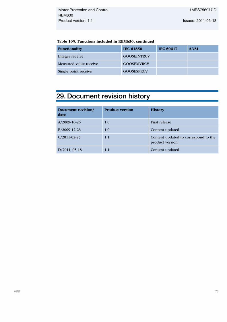
Table 105. Functions included in REM630, continued
Functionality IEC 61850 IEC 60617 ANSI
Integer receive GOOSEINTRCV
Measured value receive GOOSEMVRCV
Single point receive GOOSESPRCV
29. Document revision history
Document revision/date
Product version History
A/2009-10-26 1.0 First release
B/2009-12-23 1.0 Content updated
C/2011-02-23 1.1 Content updated to correspond to theproduct version
D/2011–05-18 1.1 Content updated
Motor Protection and Control 1MRS756977 DREM630Product version: 1.1 Issued: 2011-05-18
ABB 73

74


Contact us
ABB OyDistribution AutomationP.O. Box 699FI-65101 VAASA, FinlandPhone +358 10 22 11Fax +358 10 22 41094
www.abb.com/substationautomation
1MR
S75
6977
D©
Cop
yrig
ht 2
011
AB
B. A
ll rig
hts
rese
rved
.