1
Xiaodong JITsinghua University
Development of Replaceable Steel Coupling Beams for Enhanced Seismic
Resiliency of High-Rise Buildings
December 9, 2016

2
Chile Earthquake (2010)
Wenchuan Earthquake(2008)
Kobe Earthquake(1995)
Loma Prieta Earthquake(1989)

3
Replaceable steel coupling beam (RSCB)

4
Replaceable steel coupling beam (RSCB)

5
Tianjin 117 Tower(597 m)

6
Beijing Sancai Building (48.5 m)

• Background & motivations• Seismic design of RSCBs• Performance assessment of RSCBs
Outlines

8
Shear linkYield in shear
Beam segment
Flexural strength
Link-to-beam connection
e/(Mp/Vp)<1.6Vp=0.6fyAwYield strength
Mbp>0.5l·(ΩVp)Vbp> Ω VpShear strength
Vcp> Ω Vp
Mcp>0.5e’·(Ω Vp)Flexural strength
Shear strength
Capacity design philosophy

9
• Very short shear links• Link-to-beam connections• RC slab

10
e/(Mp/Vp) < 1.0 e/(Mp/Vp) ≈ 1.5Length ratio
RSCBs EBFs
Shear links (per AISC 341 & GB 50011)

11
0.08 rad required by AISC 341
Test of very short shear links
e/(Mp/Vp) = 0.87Length ratio:
Ji X, Wang Y, Ma Q, Okazaki T. Cyclic behavior of very short steel shear links. Journal of Structural Engineering (ASCE), 2016, 142(2): 04015114.
Hybrid section: LY 225/Q235 for link web and Q345 for flanges

Overstrength Ω = Vmax/Vn
12
n The very short shear links generated an overstrength factor of approximately 1.9, significantly exceeding the value of 1.5 assumed for EBF links in the AISC 341-10 provisions.

13
I-shaped section linkCB1: End plate connection
I-shaped section link CB2: Splice plate connection

14Epoxy adhesive fv = 15 MPa
Double channel section link CB3: Bolted web connection
Double channel section linkCB4: Adhesive web connection


16
Loading protocol
Phase I 0.02 radPhase II Fail
n Phase I: load to 0.02 rad rotation
n Phase II: load till failure
n Replacement of the shear link

17
CB1 CB2
CB3 CB4
Phase I test

18
CB1 CB2
CB3 CB4: Adhesive fracture
Phase I test
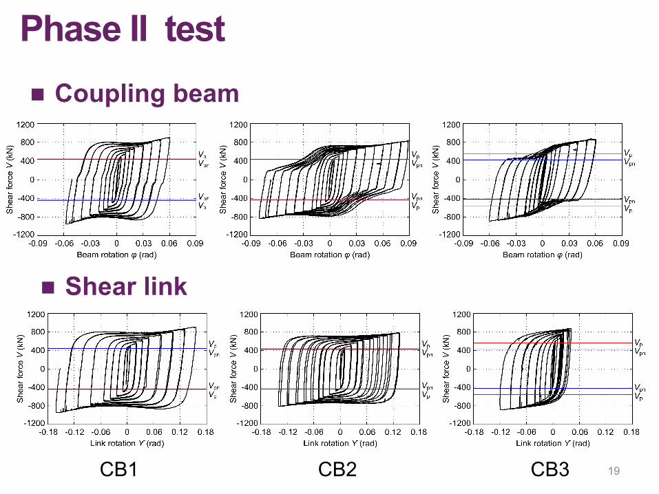
19CB1 CB2 CB3
n Coupling beam
n Shear link
Phase II test

20
Spec. No.
Connection type
Ultimate rotation
(rad)
Residual rotation for replacement
(rad)
Replacement time
(hour)
CB1 End plate connection 0.06 0.0045 0.4
CB2 Splice plate connection 0.09 0.0045 2.6
CB3 Bolted web connection 0.06 0.0065 2.2
CB4 Adhesive web connection 0.003 —— ——
Replaceability
Xiaodong Ji, Yandong Wang, Qifeng Ma, Taichiro Okazaki. Cyclic behavior of replaceable steel coupling beams. Journal of Structural Engineering (ASCE), 2016. DOI: 10.1061/(ASCE)ST.1943-541X.0001661.

21
CBS1: Composite slab

22

23
Slab damage
• At 0.04 rad beam rotation, most of shear studs pulled out from the RC slab, and the rebars were exposed and buckled.
• Shear studs are NOT recommended for use between the RSCBs and their above slabs.

24
CBS2: Isolated slab
CBS3: Bearing slab CBS4: Slotted slab
CBS1: Composite slab

25
CBS2: Isolated slab (GOOD)
CBS3: Bearing slab (FAIR) CBS4: Slotted slab (FAIR)
CBS1: Composite slab (BAD)

• Background & motivations• Seismic design of RSCBs• Performance assessment of RSCBs
Outlines

27
Damage state
Damage description Repair method Damage illustration
DS1 - Substantial slab damage
- Replacement of the portion of the slab above the
RSCB aDS2
- Web buckling- Flange buckling- Global buckling
- Heat straightening - Replacement of
shear link aDS3
- Web fracture- Flange fracture
- Replacement of the shear link a
Next generation performance assessment(FEMA P-58)

28
Damage state
Link rotation (Mean ) Repair method Damage illustration
DS1 5%
- Replacement of the portion of the slab above the
RSCB aDS2 9%
- Heat straightening
- Replacement of shear link a
DS3 11% - Replacement of the shear link a
Fragility curve of RSCB

29
Beijing Sancai Building (11 story, 48.5 m)

30
n Design basis earthquake (DBE) PGA 0.2gn Period:1.57 s (Y)、1.53 s (X)、1.26 s (Torsion)n Seismic design: linear spectrum analysis under SLE n Interstory drift ratio (SLE) < 1/800
Xiaodong Ji, Dan Liu, Ya Sun, Carlos Molina Hutt. Seismic performance assessment of a hybrid coupled wall system with replaceable steel coupling beams versus traditional RC coupling beams. Earthquake Engineering and Structural Dynamics, DOI: 10.1002/eqe.2801, 2016.

31
• Wall pier:
OpenSees model
Multi-layer shell element
Beam element + Nonlinear link element
• Coupling beam:
• Coupling ratio=0.43

32 32
Ground motions
• Seismic motions: selected from PEER database using linear scaling method
Damping ζ = 5%
• Seismic intensities: SLE, DBE, MCE, VRE

33
Interstory drift ratio
Coupling beam behavior
34
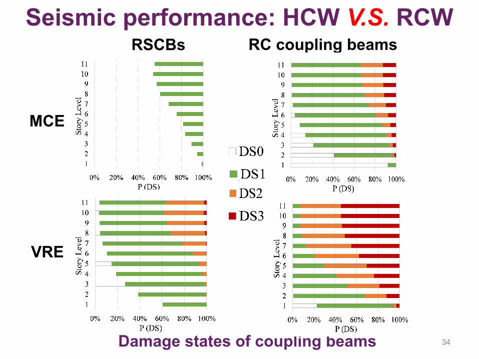
Seismic performance: HCW V.S. RCW
Damage states of coupling beams
MCE
VRE
RSCBs RC coupling beams