EUROSTEEL 2014, September 10-12, 2014, Naples, Italy BENDING – SHEAR INTERACTION IN RBS SHORT COUPLING BEAMS Andrei Crisan a , Dan Dubina b a Politehnica University Timisoara, Dept. of Steel Structures and Structural Mechanics, Romania [email protected] b Romanian Academy, Timișoara branch, CCTFA [email protected] KEYWORDS: M-V interaction, plastic hinge, experimental, numerical, RBS ABSTRACT Eurocode [1] specifies that, for plastic hinges in beams it should be verified the full plastic moment of resistance and rotation capacity are not decreased by compression or shear forces. For current moment resisting frames, low values of shear to shear capacity or axial force to axial capacity were observed in comparison to bending moment ratio. For these cases, the influence of shear and axial force on bending moment and rotation capacity of moment plastic hinges can be ignored. However, there are some cases, when the lateral force-resisting system is composed by close-spaced columns rigidly connected by beams. These beams are long enough to allow for the development of moment plastic hinges at the ends, but they are also sufficiently short to create a significantly shear forces to influence the bending moment and rotation capacity of the beam. The paper presents a parametric study using an experimentally calibrated numerical model carried- out at Department of Steel Structures and Structural Mechanics of Politehnica University Timisoara on the purpose to observe and characterise the plastic mechanism of short steel beams with Reduced Beam Section (RBS) applied in Moment Resisting Frames. Such a solution was applied to design a multi-story building structure in Bucharest, were the structural designer aimed to get a good dissipative behaviour under seismic actions in the plastic hinges expected to form in the RBS zones of the short beams of the frames. An experimental confirmation of this solution was asked and validity of plastic hinge model, applied in global analysis, to be checked. In case, an interaction model between bending moment and shear force had to be calibrated. A synthesis of the main result of this investigation is presented, including main experimental and numerical investigations, and, at the end, a simplified interaction model, compatible with SAP2000 [2] is proposed, enabling for non-linear analysis in practical design. CONCLUSIONS Five existing interaction models were used as a starting point. Based on these models, a new approach was proposed, resulting a better M – V interaction model. This interaction model is based on EN1993-1-3 model, and it’s given in Eq. (1). 1 1 2 1 5 . 1 r pl f pl V V M M M M (1) where Mpl is the plastic bending capacity of the beam Mf is bending capacity of flanges, Vr is the shear resistance of the section, M and V are the design bending moment and shear force. In the next step, the EN1993-1-3 equation was modified order to further reduce the bending moment capacity due to high values of shear force, resulting a modified equation: The results of the modified EN1993-1-3 approach are presented in Fig. 1, for FLO_F15W20 and FLO_F15W20H cases. It can be observed that the proposed approach best describes the behaviour of the considered numerical model.

Welcome message from author
This document is posted to help you gain knowledge. Please leave a comment to let me know what you think about it! Share it to your friends and learn new things together.
Transcript
EUROSTEEL 2014, September 10-12, 2014, Naples, Italy
BENDING – SHEAR INTERACTION IN RBS SHORT COUPLING BEAMS
Andrei Crisana, Dan Dubinab a Politehnica University Timisoara, Dept. of Steel Structures and Structural Mechanics, Romania
[email protected] b Romanian Academy, Timișoara branch, CCTFA
KEYWORDS: M-V interaction, plastic hinge, experimental, numerical, RBS
ABSTRACT
Eurocode [1] specifies that, for plastic hinges in beams it should be verified the full plastic moment of resistance and rotation capacity are not decreased by compression or shear forces. For current moment resisting frames, low values of shear to shear capacity or axial force to axial capacity were observed in comparison to bending moment ratio. For these cases, the influence of shear and axial force on bending moment and rotation capacity of moment plastic hinges can be ignored. However, there are some cases, when the lateral force-resisting system is composed by close-spaced columns rigidly connected by beams. These beams are long enough to allow for the development of moment plastic hinges at the ends, but they are also sufficiently short to create a significantly shear forces to influence the bending moment and rotation capacity of the beam. The paper presents a parametric study using an experimentally calibrated numerical model carried-out at Department of Steel Structures and Structural Mechanics of Politehnica University Timisoara on the purpose to observe and characterise the plastic mechanism of short steel beams with Reduced Beam Section (RBS) applied in Moment Resisting Frames. Such a solution was applied to design a multi-story building structure in Bucharest, were the structural designer aimed to get a good dissipative behaviour under seismic actions in the plastic hinges expected to form in the RBS zones of the short beams of the frames. An experimental confirmation of this solution was asked and validity of plastic hinge model, applied in global analysis, to be checked. In case, an interaction model between bending moment and shear force had to be calibrated. A synthesis of the main result of this investigation is presented, including main experimental and numerical investigations, and, at the end, a simplified interaction model, compatible with SAP2000 [2] is proposed, enabling for non-linear analysis in practical design.
CONCLUSIONS
Five existing interaction models were used as a starting point. Based on these models, a new approach was proposed, resulting a better M – V interaction model. This interaction model is based on EN1993-1-3 model, and it’s given in Eq. (1).
112
15.1
rpl
f
pl V
V
M
M
M
M (1)
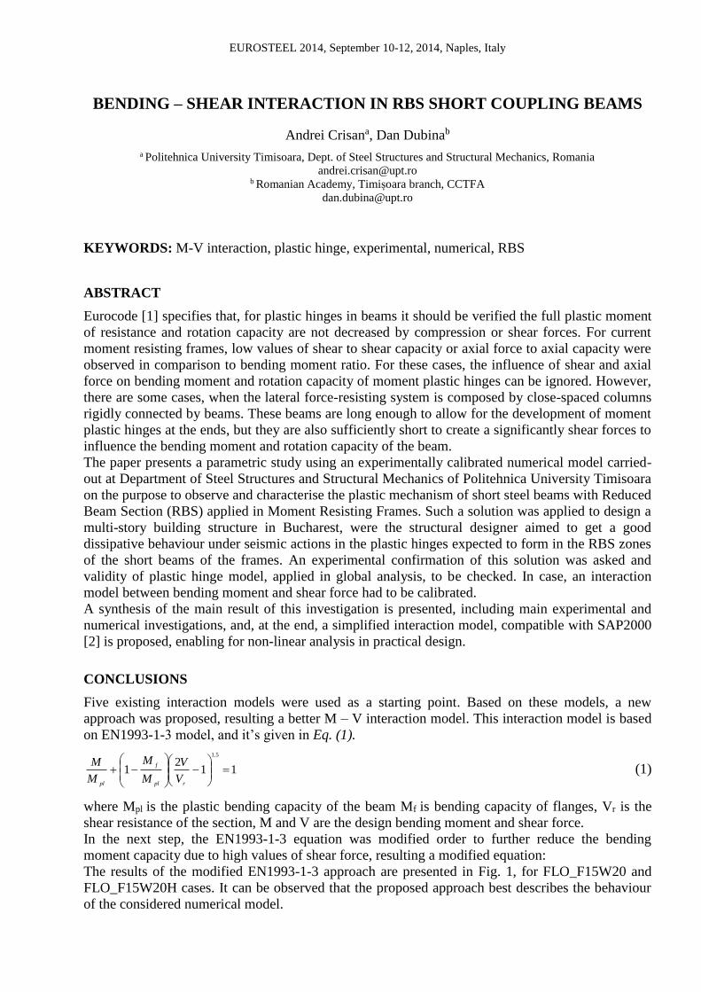
where Mpl is the plastic bending capacity of the beam Mf is bending capacity of flanges, Vr is the shear resistance of the section, M and V are the design bending moment and shear force. In the next step, the EN1993-1-3 equation was modified order to further reduce the bending moment capacity due to high values of shear force, resulting a modified equation: The results of the modified EN1993-1-3 approach are presented in Fig. 1, for FLO_F15W20 and FLO_F15W20H cases. It can be observed that the proposed approach best describes the behaviour of the considered numerical model.
0.00
0.20
0.40
0.60
0.80
1.00
0.00 0.20 0.40 0.60 0.80 1.00
Mom
ent
[M/M
pl]
Shear [V/Vpl]
FLO_F15W20
BASLER
EN1993-1-1
EN1993-1-3
AASHTO
AASHTO Modified
FEM Results
0.00
0.20
0.40
0.60
0.80
1.00
0.00 0.20 0.40 0.60 0.80 1.00
Mom
ent
[M/M
pl]
Shear [V/Vpl]
FLO_F15W20H
BASLER
EN1993-1-1
EN1993-1-3
AASHTO
AASHTO Modified
FEM Results
Fig. 1. Modified EN1993-1-3
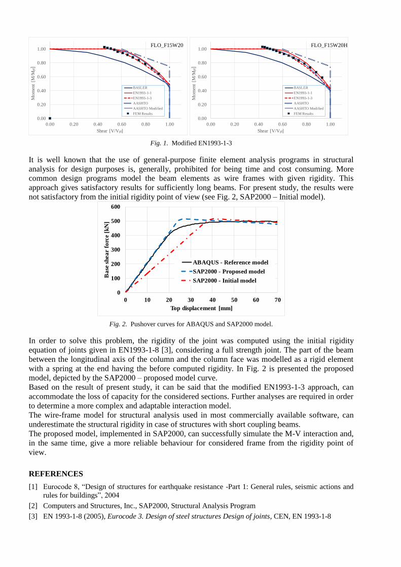
It is well known that the use of general-purpose finite element analysis programs in structural analysis for design purposes is, generally, prohibited for being time and cost consuming. More common design programs model the beam elements as wire frames with given rigidity. This approach gives satisfactory results for sufficiently long beams. For present study, the results were not satisfactory from the initial rigidity point of view (see Fig. 2, SAP2000 – Initial model).
0
100
200
300
400
500
600
0 10 20 30 40 50 60 70
Bas
e sh
ear
forc
e [k
N]
Top displacement [mm]
ABAQUS - Reference model
SAP2000 - Proposed model
SAP2000 - Initial model
Fig. 2. Pushover curves for ABAQUS and SAP2000 model.
In order to solve this problem, the rigidity of the joint was computed using the initial rigidity equation of joints given in EN1993-1-8 [3], considering a full strength joint. The part of the beam between the longitudinal axis of the column and the column face was modelled as a rigid element with a spring at the end having the before computed rigidity. In Fig. 2 is presented the proposed model, depicted by the SAP2000 – proposed model curve. Based on the result of present study, it can be said that the modified EN1993-1-3 approach, can accommodate the loss of capacity for the considered sections. Further analyses are required in order to determine a more complex and adaptable interaction model. The wire-frame model for structural analysis used in most commercially available software, can underestimate the structural rigidity in case of structures with short coupling beams. The proposed model, implemented in SAP2000, can successfully simulate the M-V interaction and, in the same time, give a more reliable behaviour for considered frame from the rigidity point of view.
REFERENCES
[1] Eurocode 8, “Design of structures for earthquake resistance -Part 1: General rules, seismic actions and rules for buildings”, 2004
[2] Computers and Structures, Inc., SAP2000, Structural Analysis Program
[3] EN 1993-1-8 (2005), Eurocode 3. Design of steel structures Design of joints, CEN, EN 1993-1-8
EUROSTEEL 2014, September 10-12, 2014, Naples, Italy
BENDING – SHEAR INTERACTION IN RBS SHORT COUPLING BEAMS
Andrei Crisana, Dan Dubinab
a Politehnica University Timisoara, Dept. of Steel Structures and Structural Mechanics, Romania [email protected]
b Romanian Academy, Timișoara branch, CCTFA [email protected]
INTRODUCTION
In structural plastic analysis, beams and columns behaviour may be modelled using concentrated
plastic hinge models, distributed plastic hinge models, or other models whose behaviour has been
demonstrated to adequately represent the plastic behaviour of the element. The model shall be
capable of representing inelastic response along the component length, except where it is shown by
equilibrium that yielding is restricted to the component ends. Where nonlinear response is expected
in a mode other than flexure, the model shall be established to represent these effects [1].
Eurocode [2] specifies that, for plastic hinges in beams it should be verified the full plastic moment
of resistance and rotation capacity are not decreased by compression or shear forces. For current
moment resisting frames, low values of shear to shear capacity or axial force to axial capacity were
observed in comparison to bending moment ratio. For these cases, the influence of shear and axial
force on bending moment and rotation capacity of moment plastic hinges can be ignored. However,
there are some cases, when the lateral force-resisting system is composed by close-spaced columns
rigidly connected by beams. These beams are long enough to allow for the development of moment
plastic hinges at the ends, but they are also sufficiently short to create a significantly shear forces to
influence the bending moment and rotation capacity of the beam.
Such beams work like intermediate length links in eccentrically braced frames under interaction
between bending moment and shear, concentrated at the ends of the link. In order to reduce the risk
of brittle failure in beam-to-column connections, either strengthening of the connection or
weakening of the beam can be applied. First approach consists in providing sufficient over-strength
to connections, for instance by means of haunches or cover plates. The second approach can take
benefit from the "Reduced Beam Section" or "dog-bone" solution that involves the removal of a
portion of the beam flanges a short distance away from the column face. In this way, the plastic
hinge is moved away from the column-to-beam flange connection, allowing stable yielding of the
beam. This approach was proven to have a successful behaviour in numerous laboratory tests [3],
[4], [5].
Present paper focuses on the bending moment and shear force interaction in short coupling beams
with Reduced Beam Section. On this purpose, a parametric study was carried out using
experimentally calibrated numerical models. The finite element models were calibrated and
validated using experimental tests performed on four full-scale specimens at the CEMSIG
Laboratory of Politehnica University Timisoara, Romania. The general-purpose finite element
analysis program ABAQUS [6] is a powerful tool but its use in civil structural analysis is limited.
On this line, a simplified interaction model, compatible with SAP2000 [7] is proposed, enabling for
nonlinear analyses in practical design.
1 SUMARY OF EXPERIMENTAL INVESTIGATIONS
The study presented hereafter is connected with the design of a 18-story office building, located in
Bucharest, Romania. The building site is located in a high seismic area, which is characterized by a
design peak ground acceleration 0.30g for a returning period of 225 years, and soft soil conditions,
with TC=1.6 s. It is noteworthy the long corner period of the soil, which in this case may affect
flexible structures. For serviceability check, the returning period is 30 years, while for collapse
prevention it is 475 years.
Lateral force-resisting system intended to create a tube-in-tube structural layout with both perimeter
and core framings steel framing composed of closely spaced columns and short beams [8]. The
central core is also made of steel framing with closely spaced columns and short beams. The ratio of
beam length-to-beam height, L/h, varies from 3.2 to 7.4, which results in seven different types of
beams. Some beams are below the general accepted inferior limit (L/h=4). The moment frame
connections employee reduced beam section connections that are generally used for beams loaded
mainly in bending.
RBS short beams have been applied in order to control by design the development of plastic hinges,
aiming to create a classical moment frame plastic mechanism dissipative model. However, since
high shear forces have been identified in the preliminary design phase, an experimental
investigation was ordered to estimate that a classic plastic bending hinge model can be applied. The
experimental program together with the numerical model calibration and validation, presented in
detail in [8], will be summarized hereafter.
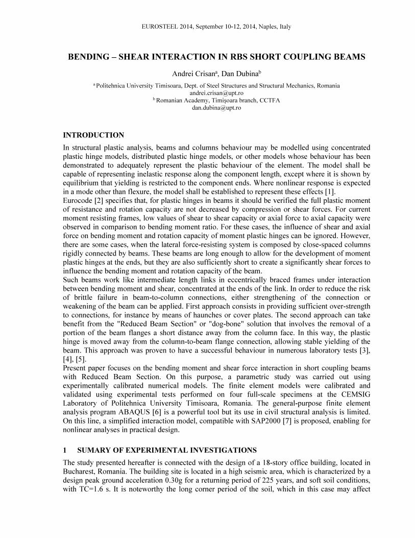
In Fig. 1 is presented the experimental setup for a full-scale frame module. Specimens were tested
under cyclic loading only.
a) b)
Fig. 1. Test setup a) and laboratory setup b) [8]
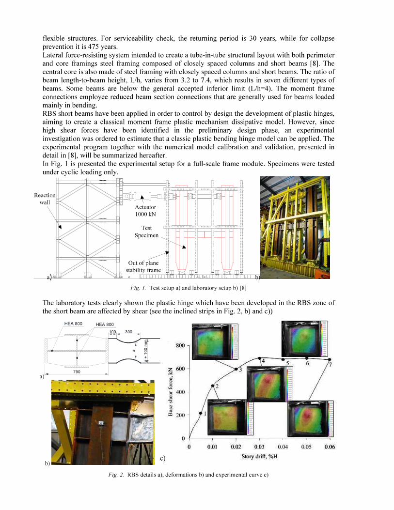
The laboratory tests clearly shown the plastic hinge which have been developed in the RBS zone of
the short beam are affected by shear (see the inclined strips in Fig. 2, b) and c))
a)
a
a +
10
0 m
m
HEA 800 HEA 800
100 300
790
b) c)
Fig. 2. RBS details a), deformations b) and experimental curve c)
Actuator
1000 kN
Test
Specimen
Out of plane
stability frame
Reaction
wall
The cyclic loading sequence was taken from the ECCS Recommendations [9]. According to the
ECCS procedure, the yielding displacement Dy and the corresponding yielding force Fy are obtained
from the monotonic force vs. displacement curve.
2 NUMERICAL SIMULATIONS AND INTERACTION MODELS
2.1 Calibration and validation of numerical models Using experimental tests as reference, the numerical models were calibrated and validated. The full
description of the numerical model is presented in [8] and summarized only hereafter.
All the components were modelled using solid elements. The engineering stress-strain curves
obtained from tensile tests were transformed into true stress – strain curves and used further for the
numerical model. The Young modulus was considered 210 000 N/mm2 and Poisson’s ratio as 0.3.
For the cyclic analysis, a combined isotropic/kinematic hardening model was used for the material,
containing the cyclic hardening parameters from [10].
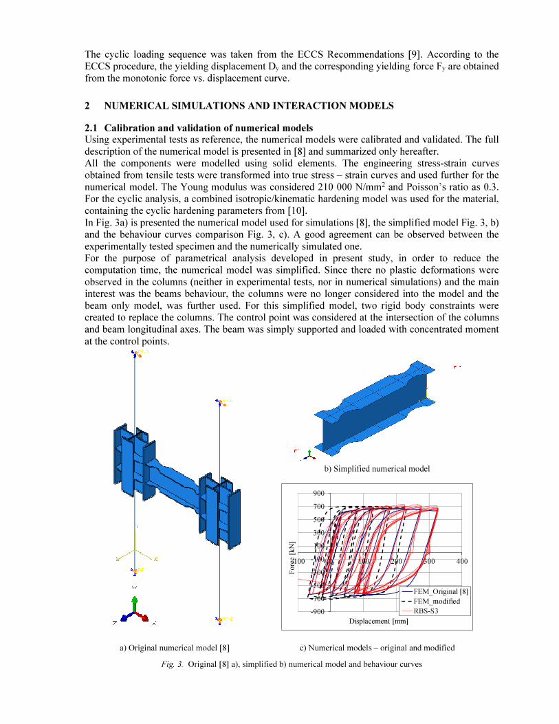
In Fig. 3a) is presented the numerical model used for simulations [8], the simplified model Fig. 3, b)
and the behaviour curves comparison Fig. 3, c). A good agreement can be observed between the
experimentally tested specimen and the numerically simulated one.
For the purpose of parametrical analysis developed in present study, in order to reduce the
computation time, the numerical model was simplified. Since there no plastic deformations were
observed in the columns (neither in experimental tests, nor in numerical simulations) and the main
interest was the beams behaviour, the columns were no longer considered into the model and the
beam only model, was further used. For this simplified model, two rigid body constraints were
created to replace the columns. The control point was considered at the intersection of the columns
and beam longitudinal axes. The beam was simply supported and loaded with concentrated moment
at the control points.
b) Simplified numerical model
-900
-700
-500
-300
-100
100
300
500
700
900
-100 0 100 200 300 400
Fo
rce [
kN
]
Displacement [mm]
FEM_Original [8]
FEM_modified
RBS-S3
a) Original numerical model [8] c) Numerical models – original and modified
Fig. 3. Original [8] a), simplified b) numerical model and behaviour curves
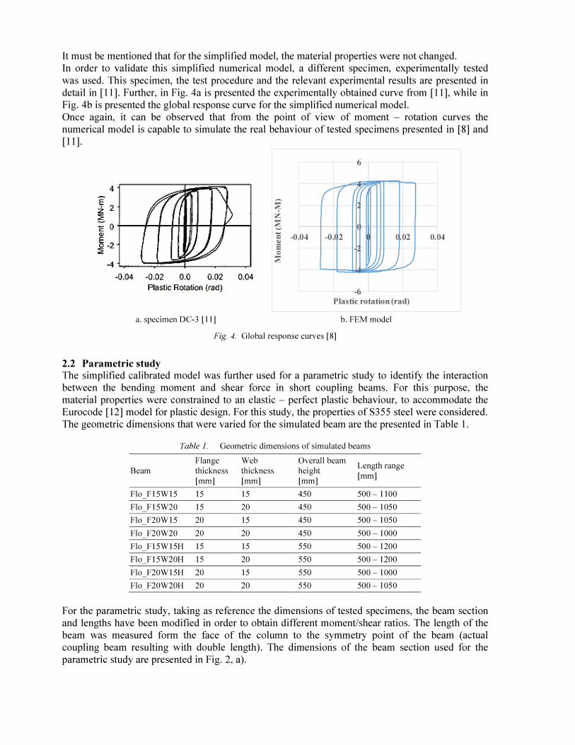
It must be mentioned that for the simplified model, the material properties were not changed.
In order to validate this simplified numerical model, a different specimen, experimentally tested
was used. This specimen, the test procedure and the relevant experimental results are presented in
detail in [11]. Further, in Fig. 4a is presented the experimentally obtained curve from [11], while in
Fig. 4b is presented the global response curve for the simplified numerical model.
Once again, it can be observed that from the point of view of moment – rotation curves the
numerical model is capable to simulate the real behaviour of tested specimens presented in [8] and
[11].
-6
-4
-2
0
2
4
6
-0.04 -0.02 0 0.02 0.04
Mo
men
t (M
N-M
)
Plastic rotation (rad)
a. specimen DC-3 [11] b. FEM model
Fig. 4. Global response curves [8]
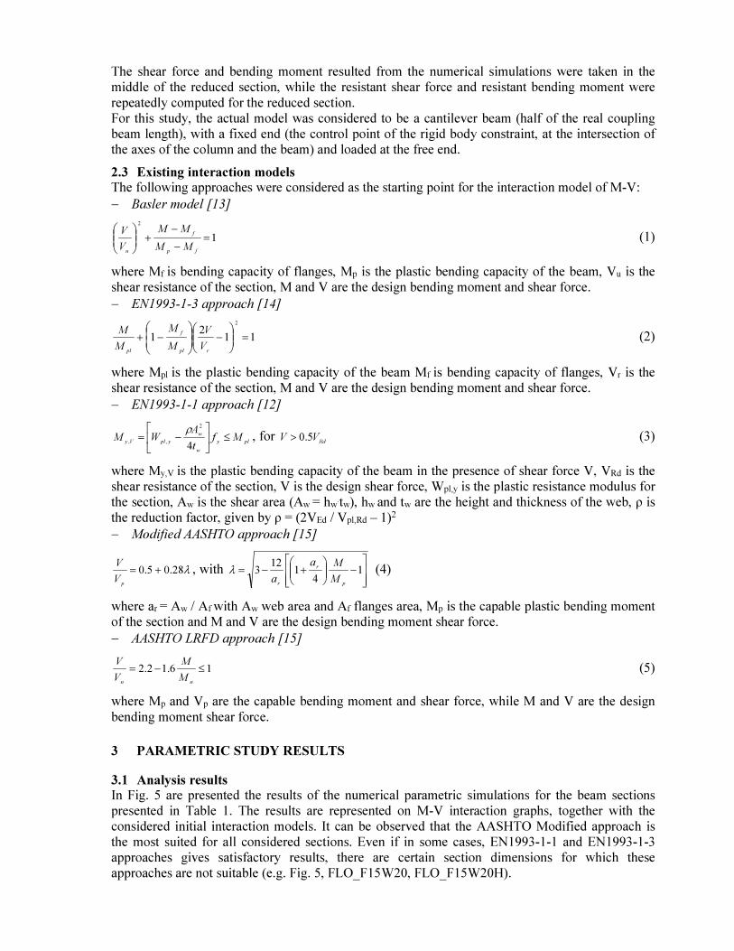
2.2 Parametric study The simplified calibrated model was further used for a parametric study to identify the interaction
between the bending moment and shear force in short coupling beams. For this purpose, the
material properties were constrained to an elastic – perfect plastic behaviour, to accommodate the
Eurocode [12] model for plastic design. For this study, the properties of S355 steel were considered.
The geometric dimensions that were varied for the simulated beam are the presented in Table 1.
Table 1. Geometric dimensions of simulated beams
Beam Flange thickness [mm]
Web thickness [mm]
Overall beam height [mm]
Length range [mm]
Flo_F15W15 15 15 450 500 – 1100
Flo_F15W20 15 20 450 500 – 1050
Flo_F20W15 20 15 450 500 – 1050
Flo_F20W20 20 20 450 500 – 1000
Flo_F15W15H 15 15 550 500 – 1200
Flo_F15W20H 15 20 550 500 – 1200
Flo_F20W15H 20 15 550 500 – 1000
Flo_F20W20H 20 20 550 500 – 1050
For the parametric study, taking as reference the dimensions of tested specimens, the beam section
and lengths have been modified in order to obtain different moment/shear ratios. The length of the
beam was measured form the face of the column to the symmetry point of the beam (actual
coupling beam resulting with double length). The dimensions of the beam section used for the
parametric study are presented in Fig. 2, a).
The shear force and bending moment resulted from the numerical simulations were taken in the
middle of the reduced section, while the resistant shear force and resistant bending moment were
repeatedly computed for the reduced section.
For this study, the actual model was considered to be a cantilever beam (half of the real coupling
beam length), with a fixed end (the control point of the rigid body constraint, at the intersection of
the axes of the column and the beam) and loaded at the free end.
2.3 Existing interaction models The following approaches were considered as the starting point for the interaction model of M-V:
− Basler model [13]
1
2
=−
−+
fp
f
uMM
MM
V
V (1)
where Mf is bending capacity of flanges, Mp is the plastic bending capacity of the beam, Vu is the
shear resistance of the section, M and V are the design bending moment and shear force.
− EN1993-1-3 approach [14]
112
1
2
=
−
−+
rpl
f
plV
V
M
M
M
M (2)
where Mpl is the plastic bending capacity of the beam Mf is bending capacity of flanges, Vr is the
shear resistance of the section, M and V are the design bending moment and shear force.
− EN1993-1-1 approach [12]
ply
w
w
yplVyMf
t
AWM ≤
−=
4
2
,,
ρ, for
RdVV 5.0> (3)
where My,V is the plastic bending capacity of the beam in the presence of shear force V, VRd is the
shear resistance of the section, V is the design shear force, Wpl,y is the plastic resistance modulus for
the section, Aw is the shear area (Aw = hw.tw), hw
and tw are the height and thickness of the web, ρ is
the reduction factor, given by ρ = (2VEd / Vpl,Rd – 1)2
− Modified AASHTO approach [15]
λ28.05.0 +=
pV
V, with
−
+−= 1
41
123
p
r
rM
Ma
aλ (4)
where ar = Aw / Af with Aw web area and Af flanges area, Mp is the capable plastic bending moment
of the section and M and V are the design bending moment shear force.
− AASHTO LRFD approach [15]
16.12.2 ≤−=
nnM
M
V
V (5)
where Mp and Vp are the capable bending moment and shear force, while M and V are the design
bending moment shear force.
3 PARAMETRIC STUDY RESULTS
3.1 Analysis results In Fig. 5 are presented the results of the numerical parametric simulations for the beam sections
presented in Table 1. The results are represented on M-V interaction graphs, together with the
considered initial interaction models. It can be observed that the AASHTO Modified approach is
the most suited for all considered sections. Even if in some cases, EN1993-1-1 and EN1993-1-3
approaches gives satisfactory results, there are certain section dimensions for which these
approaches are not suitable (e.g. Fig. 5, FLO_F15W20, FLO_F15W20H).
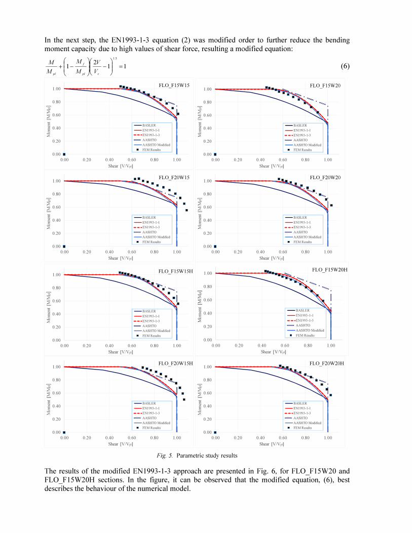
In the next step, the EN1993-1-3 equation (2) was modified order to further reduce the bending
moment capacity due to high values of shear force, resulting a modified equation:
112
1
5.1
=
−
−+
rpl
f
plV
V
M
M
M
M (6)
0.00
0.20
0.40
0.60
0.80
1.00
0.00 0.20 0.40 0.60 0.80 1.00
Mo
men
t [M
/Mpl]
Shear [V/Vpl]
FLO_F15W15
BASLER
EN1993-1-1
EN1993-1-3
AASHTO
AASHTO Modified
FEM Results
0.00
0.20
0.40
0.60
0.80
1.00
0.00 0.20 0.40 0.60 0.80 1.00
Mo
men
t [M
/Mpl]
Shear [V/Vpl]
FLO_F15W20
BASLER
EN1993-1-1
EN1993-1-3
AASHTO
AASHTO Modified
FEM Results
0.00
0.20
0.40
0.60
0.80
1.00
0.00 0.20 0.40 0.60 0.80 1.00
Mo
men
t [M
/Mpl]
Shear [V/Vpl]
FLO_F20W15
BASLER
EN1993-1-1
EN1993-1-3
AASHTO
AASHTO Modified
FEM Results
0.00
0.20
0.40
0.60
0.80
1.00
0.00 0.20 0.40 0.60 0.80 1.00
Mo
men
t [M
/Mpl]
Shear [V/Vpl]
FLO_F20W20
BASLER
EN1993-1-1
EN1993-1-3
AASHTO
AASHTO Modified
FEM Results
0.00
0.20
0.40
0.60
0.80
1.00
0.00 0.20 0.40 0.60 0.80 1.00
Mo
men
t [M
/Mpl]
Shear [V/Vpl]
FLO_F15W15H
BASLER
EN1993-1-1
EN1993-1-3
AASHTO
AASHTO Modified
FEM Results
0.00
0.20
0.40
0.60
0.80
1.00
0.00 0.20 0.40 0.60 0.80 1.00
Mo
men
t [M
/Mpl]
Shear [V/Vpl]
FLO_F15W20H
BASLER
EN1993-1-1
EN1993-1-3
AASHTO
AASHTO Modified
FEM Results
0.00
0.20
0.40
0.60
0.80
1.00
0.00 0.20 0.40 0.60 0.80 1.00
Mo
men
t [M
/Mpl]
Shear [V/Vpl]
FLO_F20W15H
BASLER
EN1993-1-1
EN1993-1-3
AASHTO
AASHTO Modified
FEM Results
0.00
0.20
0.40
0.60
0.80
1.00
0.00 0.20 0.40 0.60 0.80 1.00
Mo
men
t [M
/Mpl]
Shear [V/Vpl]
FLO_F20W20H
BASLER
EN1993-1-1
EN1993-1-3
AASHTO
AASHTO Modified
FEM Results
Fig. 5. Parametric study results
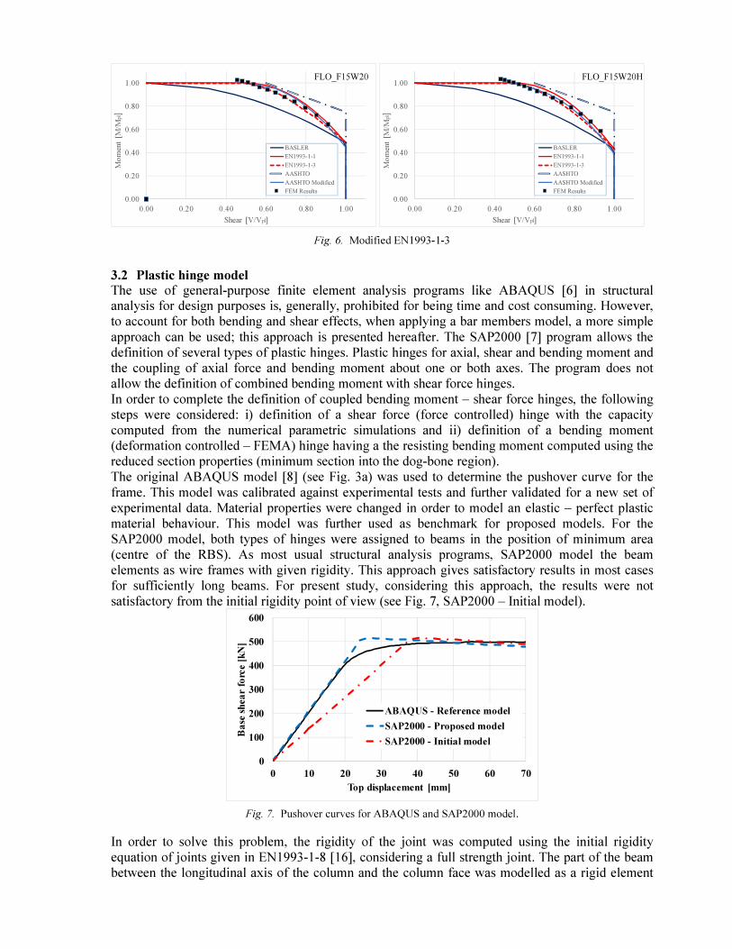
The results of the modified EN1993-1-3 approach are presented in Fig. 6, for FLO_F15W20 and
FLO_F15W20H sections. In the figure, it can be observed that the modified equation, (6), best
describes the behaviour of the numerical model.
0.00
0.20
0.40
0.60
0.80
1.00
0.00 0.20 0.40 0.60 0.80 1.00
Mo
men
t [M
/Mpl]
Shear [V/Vpl]
FLO_F15W20
BASLER
EN1993-1-1
EN1993-1-3
AASHTO
AASHTO Modified
FEM Results
0.00
0.20
0.40
0.60
0.80
1.00
0.00 0.20 0.40 0.60 0.80 1.00
Mo
men
t [M
/Mpl]
Shear [V/Vpl]
FLO_F15W20H
BASLER
EN1993-1-1
EN1993-1-3
AASHTO
AASHTO Modified
FEM Results
Fig. 6. Modified EN1993-1-3
3.2 Plastic hinge model The use of general-purpose finite element analysis programs like ABAQUS [6] in structural analysis for design purposes is, generally, prohibited for being time and cost consuming. However,
to account for both bending and shear effects, when applying a bar members model, a more simple
approach can be used; this approach is presented hereafter. The SAP2000 [7] program allows the
definition of several types of plastic hinges. Plastic hinges for axial, shear and bending moment and
the coupling of axial force and bending moment about one or both axes. The program does not
allow the definition of combined bending moment with shear force hinges.
In order to complete the definition of coupled bending moment – shear force hinges, the following
steps were considered: i) definition of a shear force (force controlled) hinge with the capacity
computed from the numerical parametric simulations and ii) definition of a bending moment
(deformation controlled – FEMA) hinge having a the resisting bending moment computed using the
reduced section properties (minimum section into the dog-bone region).
The original ABAQUS model [8] (see Fig. 3a) was used to determine the pushover curve for the
frame. This model was calibrated against experimental tests and further validated for a new set of
experimental data. Material properties were changed in order to model an elastic – perfect plastic
material behaviour. This model was further used as benchmark for proposed models. For the
SAP2000 model, both types of hinges were assigned to beams in the position of minimum area
(centre of the RBS). As most usual structural analysis programs, SAP2000 model the beam
elements as wire frames with given rigidity. This approach gives satisfactory results in most cases
for sufficiently long beams. For present study, considering this approach, the results were not
satisfactory from the initial rigidity point of view (see Fig. 7, SAP2000 – Initial model).
0
100
200
300
400
500
600
0 10 20 30 40 50 60 70
Ba
se s
hea
r fo
rce [
kN
]
Top displacement [mm]
ABAQUS - Reference model
SAP2000 - Proposed model
SAP2000 - Initial model
Fig. 7. Pushover curves for ABAQUS and SAP2000 model.
In order to solve this problem, the rigidity of the joint was computed using the initial rigidity
equation of joints given in EN1993-1-8 [16], considering a full strength joint. The part of the beam
between the longitudinal axis of the column and the column face was modelled as a rigid element
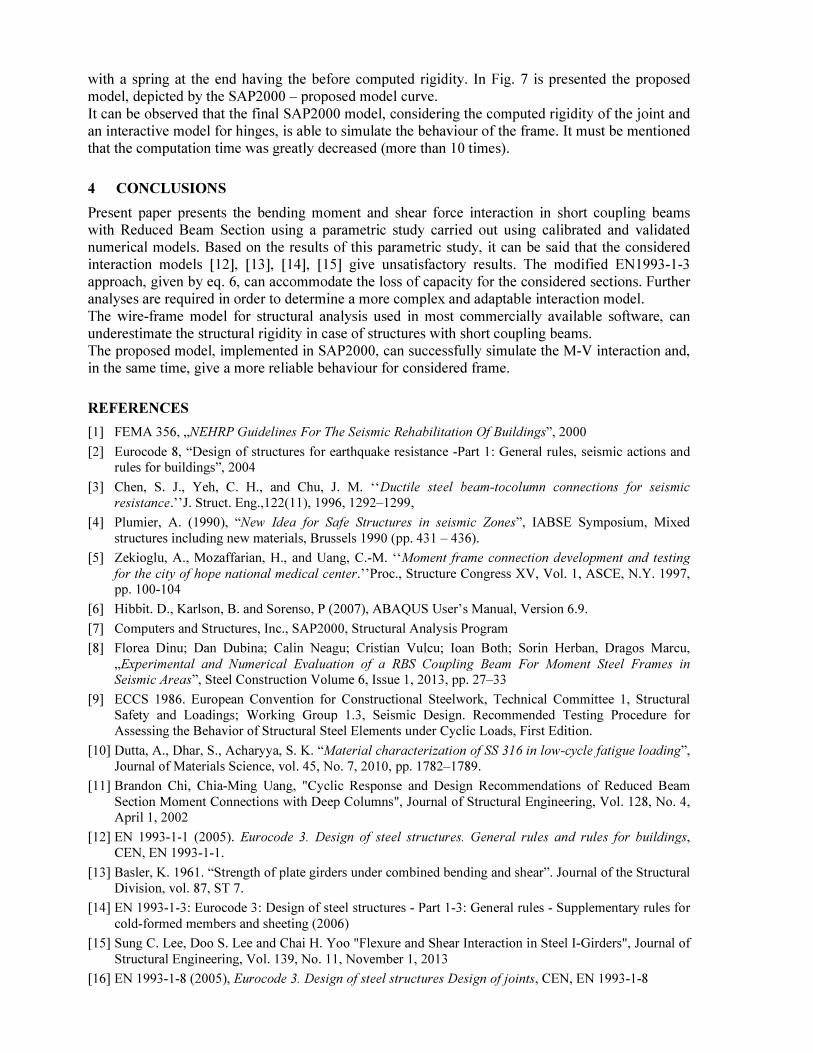
with a spring at the end having the before computed rigidity. In Fig. 7 is presented the proposed
model, depicted by the SAP2000 – proposed model curve.
It can be observed that the final SAP2000 model, considering the computed rigidity of the joint and
an interactive model for hinges, is able to simulate the behaviour of the frame. It must be mentioned
that the computation time was greatly decreased (more than 10 times).
4 CONCLUSIONS
Present paper presents the bending moment and shear force interaction in short coupling beams
with Reduced Beam Section using a parametric study carried out using calibrated and validated
numerical models. Based on the results of this parametric study, it can be said that the considered
interaction models [12], [13], [14], [15] give unsatisfactory results. The modified EN1993-1-3
approach, given by eq. 6, can accommodate the loss of capacity for the considered sections. Further
analyses are required in order to determine a more complex and adaptable interaction model.
The wire-frame model for structural analysis used in most commercially available software, can
underestimate the structural rigidity in case of structures with short coupling beams.
The proposed model, implemented in SAP2000, can successfully simulate the M-V interaction and,
in the same time, give a more reliable behaviour for considered frame.
REFERENCES
[1] FEMA 356, „NEHRP Guidelines For The Seismic Rehabilitation Of Buildings”, 2000
[2] Eurocode 8, “Design of structures for earthquake resistance -Part 1: General rules, seismic actions and
rules for buildings”, 2004
[3] Chen, S. J., Yeh, C. H., and Chu, J. M. ‘‘Ductile steel beam-tocolumn connections for seismic
resistance.’’J. Struct. Eng.,122(11), 1996, 1292–1299,
[4] Plumier, A. (1990), “New Idea for Safe Structures in seismic Zones”, IABSE Symposium, Mixed
structures including new materials, Brussels 1990 (pp. 431 – 436).
[5] Zekioglu, A., Mozaffarian, H., and Uang, C.-M. ‘‘Moment frame connection development and testing
for the city of hope national medical center.’’Proc., Structure Congress XV, Vol. 1, ASCE, N.Y. 1997,
pp. 100-104
[6] Hibbit. D., Karlson, B. and Sorenso, P (2007), ABAQUS User’s Manual, Version 6.9.
[7] Computers and Structures, Inc., SAP2000, Structural Analysis Program
[8] Florea Dinu; Dan Dubina; Calin Neagu; Cristian Vulcu; Ioan Both; Sorin Herban, Dragos Marcu,
„Experimental and Numerical Evaluation of a RBS Coupling Beam For Moment Steel Frames in
Seismic Areas”, Steel Construction Volume 6, Issue 1, 2013, pp. 27–33
[9] ECCS 1986. European Convention for Constructional Steelwork, Technical Committee 1, Structural
Safety and Loadings; Working Group 1.3, Seismic Design. Recommended Testing Procedure for
Assessing the Behavior of Structural Steel Elements under Cyclic Loads, First Edition.
[10] Dutta, A., Dhar, S., Acharyya, S. K. “Material characterization of SS 316 in low-cycle fatigue loading”,
Journal of Materials Science, vol. 45, No. 7, 2010, pp. 1782–1789.
[11] Brandon Chi, Chia-Ming Uang, "Cyclic Response and Design Recommendations of Reduced Beam
Section Moment Connections with Deep Columns", Journal of Structural Engineering, Vol. 128, No. 4,
April 1, 2002
[12] EN 1993-1-1 (2005). Eurocode 3. Design of steel structures. General rules and rules for buildings,
CEN, EN 1993-1-1.
[13] Basler, K. 1961. “Strength of plate girders under combined bending and shear”. Journal of the Structural
Division, vol. 87, ST 7.
[14] EN 1993-1-3: Eurocode 3: Design of steel structures - Part 1-3: General rules - Supplementary rules for
cold-formed members and sheeting (2006)
[15] Sung C. Lee, Doo S. Lee and Chai H. Yoo "Flexure and Shear Interaction in Steel I-Girders", Journal of
Structural Engineering, Vol. 139, No. 11, November 1, 2013
[16] EN 1993-1-8 (2005), Eurocode 3. Design of steel structures Design of joints, CEN, EN 1993-1-8
Related Documents