This content has been downloaded from IOPscience. Please scroll down to see the full text.
Download details:
IP Address: 131.188.201.33
This content was downloaded on 04/12/2013 at 06:46
Please note that terms and conditions apply.
Biosilicate®–gelatine bone scaffolds by the foam replica technique: development and
characterization
View the table of contents for this issue, or go to the journal homepage for more
2013 Sci. Technol. Adv. Mater. 14 045008
(http://iopscience.iop.org/1468-6996/14/4/045008)
Home Search Collections Journals About Contact us My IOPscience
IOP PUBLISHING SCIENCE AND TECHNOLOGY OF ADVANCED MATERIALS
Sci. Technol. Adv. Mater. 14 (2013) 045008 (11pp) doi:10.1088/1468-6996/14/4/045008
Biosilicate R©–gelatine bone scaffolds by thefoam replica technique: development andcharacterizationDeborah Desimone1, Wei Li1, Judith A Roether2, Dirk W Schubert2,Murilo C Crovace3, Ana Candida M Rodrigues3, Edgar D Zanotto3
and Aldo R Boccaccini1
1 Institute of Biomaterials, Department of Materials Science and Engineering, University ofErlangen-Nuremberg, Cauerstrasse 6, D-91058 Erlangen, Germany2 Institute of Polymer Materials, Department of Materials Science and Engineering, University ofErlangen-Nuremberg, Martensstrasse 7, D-91058 Erlangen, Germany3 Vitreous Materials Laboratory, Department of Materials Engineering, Federal University of Sao Carlos,Sao Carlos, Sao Paulo, Brazil
E-mail: [email protected]
Received 7 April 2013Accepted for publication 11 July 2013Published 13 August 2013Online at stacks.iop.org/STAM/14/045008
AbstractThe development of bioactive glass-ceramic materials has been a topic of great interest aimingat enhancing the mechanical strength of traditional bioactive scaffolds. In the present study,we test and demonstrate the use of Biosilicate R© glass-ceramic powder to fabricate bonescaffolds by the foam replica method. Scaffolds possessing the main requirements for use inbone tissue engineering (95% porosity, 200–500 µm pore size) were successfully produced.Gelatine coating was investigated as a simple approach to increase the mechanical competenceof the scaffolds. The gelatine coating did not affect the interconnectivity of the pores and didnot significantly affect the bioactivity of the Biosilicate R© scaffold. The gelatine coatingsignificantly improved the compressive strength (i.e. 0.80 ± 0.05 MPa of coated versus0.06 ± 0.01 MPa of uncoated scaffolds) of the Biosilicate R© scaffold. The combination ofBiosilicate R© glass-ceramic and gelatine is attractive for producing novel scaffolds for bonetissue engineering.
Keywords: bioactivity, glass-ceramics, scaffolds, bone tissue engineering
1. Introduction
Bioactive glasses and glass-ceramics are being employed inbone tissue engineering to manufacture scaffolds to replicatebone structure, allowing the cells to adhere, proliferate,differentiate and organize into normal healthy bone asthe scaffold degrades [1–5]. Besides the specific criteriafor bone tissue engineering, such as osteoconductivity,biodegradability, high porosity (>90%) and pore size greater
Content from this work may be used under the terms of theCreative Commons Attribution-NonCommercial-ShareAlike
3.0 licence. Any further distribution of this work must maintain attribution tothe author(s) and the title of the work, journal citation and DOI.
than 100 µm [6], mechanical integrity is imperative for thescaffolds to be easily manipulated by cell biologists andsurgeons, and to allow their use in load-bearing implants forin situ bone regeneration. Hence, research has focused onthe development of biodegradable scaffolds with comparablemechanical behaviour to bone [5].
Novel bioactive glass-ceramic materials are beingdeveloped in this context, considering their potential superiormechanical properties and machinability compared to thestandard 45S5 Bioglass R© [7, 8]. A fully crystallized glass-ceramic of the system P2O5–Na2O–CaO–SiO2, labelledBiosilicate R©, has been developed which exhibits high bio-activity and enhanced in vitro bone-like tissue formation [9].
1468-6996/13/045008+11$33.00 1 © 2013 National Institute for Materials Science Printed in the UK
Sci. Technol. Adv. Mater. 14 (2013) 045008 D Desimone et al
A recent in vivo study [10] showed that Biosilicate R©
scaffolds produced by the addition of porogen agents arebiocompatible and non-cytotoxic. Moreover, since 2004,this material has been successfully tested in vitro and hasbeen employed in clinical trials for the treatment of dentinhypersensitivity [11, 12].
The consolidation of glass-ceramic materials into highlyporous mechanically sound scaffolds, however, is difficultby the intrinsically lower content of the residual vitreousphase, compared with (fully amorphous) glasses. On the otherhand, melting of the crystalline phases present in the startingglass-ceramic material at elevated temperatures may result inthe total densification of the porous structure.
This work describes the development of Biosilicate R©
scaffolds using the foam replica technique, originally reportedfor bioactive silicate systems by Chen et al [13]. The highinterconnected porosity (>90%) obtained by the foam replicatechnique should lead to scaffolds that are suitable for cellinvasion and vascularization during new bone formation.Reinforcement of the Biosilicate R© scaffolds by gelatinecoating was also investigated and the effect of the gelatinecoating on the compressive strength and bioactivity of thescaffolds was assessed. The application of gelatine coatingson bioceramic scaffolds has been investigated recently,showing that such coatings can significantly improve themechanical properties of bioactive glass and bioceramicscaffolds [14–19]. In addition, the novel gelatine-coated shellscaffolds recently developed by Bellucci et al [19] using anew protocol for the foam replica technique not only combinehigh internal porosity and an external resistant surface but alsomaintain the bioactivity in simulated body fluid (SBF) [19].
Previously, porous Biosilicate R© scaffolds (77% openporosity and 5% closed porosity) were obtained by additionof carbon black as a porogen agent [10]. In our study, for thefirst time, Biosilicate R© scaffolds with highly interconnectedpore structure and high porosity (>90%) have been fabricatedby the foam replica technique. Also for the first time, in thepresent investigation Biosilicate R© foam-like scaffolds weresurface functionalized by gelatine coating.
2. Experimental
2.1. Materials and methods
Biosilicate R© scaffolds were produced by the replicatechnique, according to the method described elsewhere [13].The starting powder used consisted of a totally crystallizedglass-ceramic with a particle size of 5 µm and a liquidustemperature of 1230 ◦C. The slurry for scaffold fabricationwas prepared by dissolving polyvinyl alcohol (Mw ∼ 30 000,Merck, Germany) in water at a concentration of 0.01 mol l−1
and adding the Biosilicate R© powder at two investigatedconcentrations (40 and 60 wt.%). Polyurethane foam (45pores per inch, Eurofoam, Germany) was employed as thesacrificial pre-form. The infiltration for 1 min was repeatedtwo or three times, with a drying step at room temperaturefor 24 h between each coating.
In order to identify the most adequate temperaturefor scaffold sintering, the starting Biosilicate R© powder
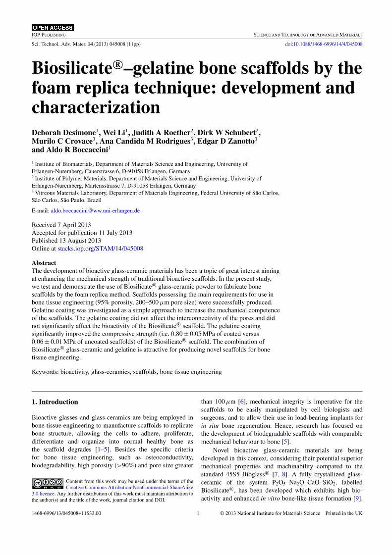
Figure 1. Linear shrinkage (solid line) and DSC (dashed line)curves for the Biosilicate R© powder compact at a heating rate of2 ◦C min−1.
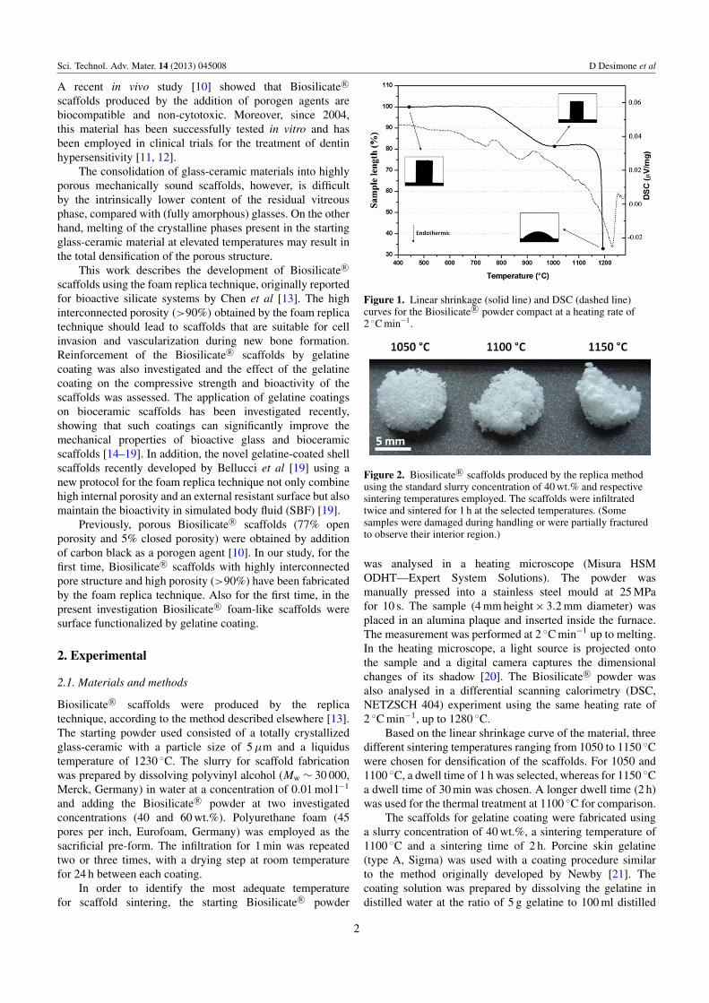
Figure 2. Biosilicate R© scaffolds produced by the replica methodusing the standard slurry concentration of 40 wt.% and respectivesintering temperatures employed. The scaffolds were infiltratedtwice and sintered for 1 h at the selected temperatures. (Somesamples were damaged during handling or were partially fracturedto observe their interior region.)
was analysed in a heating microscope (Misura HSMODHT—Expert System Solutions). The powder wasmanually pressed into a stainless steel mould at 25 MPafor 10 s. The sample (4 mm height × 3.2 mm diameter) wasplaced in an alumina plaque and inserted inside the furnace.The measurement was performed at 2 ◦C min−1 up to melting.In the heating microscope, a light source is projected ontothe sample and a digital camera captures the dimensionalchanges of its shadow [20]. The Biosilicate R© powder wasalso analysed in a differential scanning calorimetry (DSC,NETZSCH 404) experiment using the same heating rate of2 ◦C min−1, up to 1280 ◦C.
Based on the linear shrinkage curve of the material, threedifferent sintering temperatures ranging from 1050 to 1150 ◦Cwere chosen for densification of the scaffolds. For 1050 and1100 ◦C, a dwell time of 1 h was selected, whereas for 1150 ◦Ca dwell time of 30 min was chosen. A longer dwell time (2 h)was used for the thermal treatment at 1100 ◦C for comparison.
The scaffolds for gelatine coating were fabricated usinga slurry concentration of 40 wt.%, a sintering temperature of1100 ◦C and a sintering time of 2 h. Porcine skin gelatine(type A, Sigma) was used with a coating procedure similarto the method originally developed by Newby [21]. Thecoating solution was prepared by dissolving the gelatine indistilled water at the ratio of 5 g gelatine to 100 ml distilled
2
Sci. Technol. Adv. Mater. 14 (2013) 045008 D Desimone et al
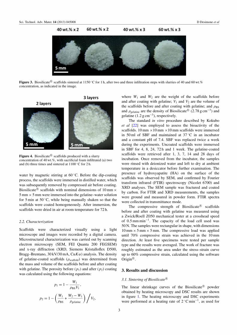
Figure 3. Biosilicate R© scaffolds sintered at 1150 ◦C for 1 h, after two and three infiltration steps with slurries of 40 and 60 wt.%concentration, as indicated in the image.
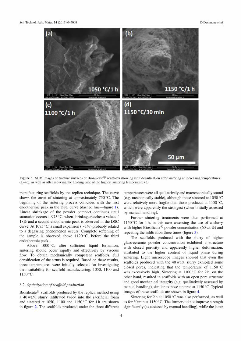
Figure 4. Biosilicate R© scaffolds produced with a slurryconcentration of 40 wt.%, with sacrificial foam infiltrated (a) twoand (b) three times and sintered at 1100 ◦C for 2 h.
water by magnetic stirring at 60 ◦C. Before the dip-coatingprocess, the scaffolds were immersed in distilled water, whichwas subsequently removed by compressed air before coating.Biosilicate R© scaffolds with nominal dimensions of 10 mm ×
5 mm × 5 mm were immersed into the gelatine–water solutionfor 5 min at 50 ◦C, while being manually shaken so that thescaffolds were coated homogeneously. After immersion, thescaffolds were dried in air at room temperature for 72 h.
2.2. Characterization
Scaffolds were characterized visually using a lightmicroscope and images were recorded by a digital camera.Microstructural characterization was carried out by scanningelectron microscopy (SEM, FEI Quanta 200 FEGSEM)and x-ray diffraction (XRD, Siemens Kristalloflex D500,Bragg–Brentano, 30 kV/30 mA, CuKα) analysis. The densityof gelatine-coated scaffolds (ρscaffold) was determined fromthe mass and volume of the scaffolds before and after coatingwith gelatine. The porosity before (p1) and after (p2) coatingwas calculated using the following equations:
p1 = 1 −W1
ρBSV1,
p2 = 1 −
(W1
ρBS+
W2 − W1
ρgelatine
) /V2,
where W1 and W2 are the weight of the scaffolds beforeand after coating with gelatine; V1 and V2 are the volume ofthe scaffolds before and after coating with gelatine; and ρBS
and ρgelatine are the density of Biosilicate R© (2.78 g cm−3) andgelatine (1.2 g cm−3), respectively.
The standard in vitro procedure described by Kokuboet al [22] was employed to assess the bioactivity of thescaffolds. 10 mm ×10 mm ×10 mm scaffolds were immersedin 50 ml of SBF and maintained at 37 ◦C in an incubatorand a constant pH of 7.4. SBF was replaced twice a weekduring the experiments. Uncoated scaffolds were immersedin SBF for 4, 8, 24, 72 h and 1 week. The gelatine-coatedscaffolds were retrieved after 1, 3, 7, 14 and 28 days ofincubation. Once removed from the incubator, the sampleswere rinsed with deionized water and left to dry at ambienttemperature in a desiccator before further examination. Thepresence of hydroxyapatite (HA) on the surface of thescaffolds was observed by SEM, and confirmed by Fouriertransform infrared (FTIR) spectroscopy (Nicolet 6700) andXRD analyses. The SEM sample was fractured and coatedby carbon. For FTIR and XRD measurements, the sampleswere ground and measured in powder form. FTIR spectrawere collected in transmittance mode.
The compressive strength of Biosilicate R© scaffoldsbefore and after coating with gelatine was measured usinga Zwick/Roell Z050 mechanical tester at a crosshead speedof 0.5 mm min−1. The capacity of the load cell used was50 N. The samples were rectangular in shape, with dimensions10 mm × 5 mm × 5 mm. The compressive load was applieduntil 70% compressive strain was achieved in the 10 mmdirection. At least five specimens were tested per sampletype and the results were averaged. The work of fracture wasroughly estimated as the area under the stress–strain curveup to 60% compressive strain, calculated using the softwareOrigin R©.
3. Results and discussion
3.1. Sintering of Biosilicate R©
The linear shrinkage curves of the Biosilicate R© powderobtained by heating microscopy and DSC results are shownin figure 1. The heating microscopy and DSC experimentswere performed at a heating rate of 2 ◦C min−1, as used for
3
Sci. Technol. Adv. Mater. 14 (2013) 045008 D Desimone et al
Figure 5. SEM images of fracture surfaces of Biosilicate R© scaffolds showing strut densification after sintering at increasing temperatures(a)–(c), as well as after reducing the holding time at the highest sintering temperature (d).
manufacturing scaffolds by the replica technique. The curveshows the onset of sintering at approximately 750 ◦C. Thebeginning of the sintering process coincides with the firstendothermic peak in the DSC curve (dashed line—figure 1).Linear shrinkage of the powder compact continues untilsaturation occurs at 975 ◦C, when shrinkage reaches a value of18% and a second endothermic peak is observed in the DSCcurve. At 1075 ◦C, a small expansion (∼1%) probably relatedto a degassing phenomenon occurs. Complete softening ofthe sample is observed above 1120 ◦C, before the thirdendothermic peak.
Above 1000 ◦C, after sufficient liquid formation,sintering should occur rapidly and effectively by viscousflow. To obtain mechanically competent scaffolds, fulldensification of the struts is required. Based on these results,three temperatures were initially selected for investigatingtheir suitability for scaffold manufacturing: 1050, 1100 and1150 ◦C.
3.2. Optimization of scaffold production
Biosilicate R© scaffolds produced by the replica method usinga 40 wt.% slurry infiltrated twice into the sacrificial foamand sintered at 1050, 1100 and 1150 ◦C for 1 h are shownin figure 2. The scaffolds produced under the three different
temperatures were all qualitatively and macroscopically sound(e.g. mechanically stable), although those sintered at 1050 ◦Cwere relatively more fragile than those produced at 1150 ◦C,which were apparently the strongest (when initially assessedby manual handling).
Further sintering treatments were thus performed at1150 ◦C for 1 h, in this case assessing the use of a slurrywith higher Biosilicate R© powder concentration (60 wt.%) andrepeating the infiltration three times (figure 3).
The scaffolds produced with the slurry of higherglass-ceramic powder concentration exhibited a structurewith closed porosity and apparently higher deformation,attributed to the higher content of liquid phase duringsintering. Light microscope images showed that even thescaffolds produced with the 40 wt.% slurry exhibited someclosed pores, indicating that the temperature of 1150 ◦Cwas excessively high. Sintering at 1100 ◦C for 2 h, on theother hand, resulted in scaffolds with an open pore structureand good mechanical integrity (e.g. qualitatively assessed bymanual handling), similar to those sintered at 1150 ◦C. Typicalimages of these scaffolds are shown in figure 4.
Sintering for 2 h at 1050 ◦C was also performed, as wellas for 30 min at 1150 ◦C. The former did not improve strengthsignificantly (as assessed by manual handling), while the latter
4
Sci. Technol. Adv. Mater. 14 (2013) 045008 D Desimone et al
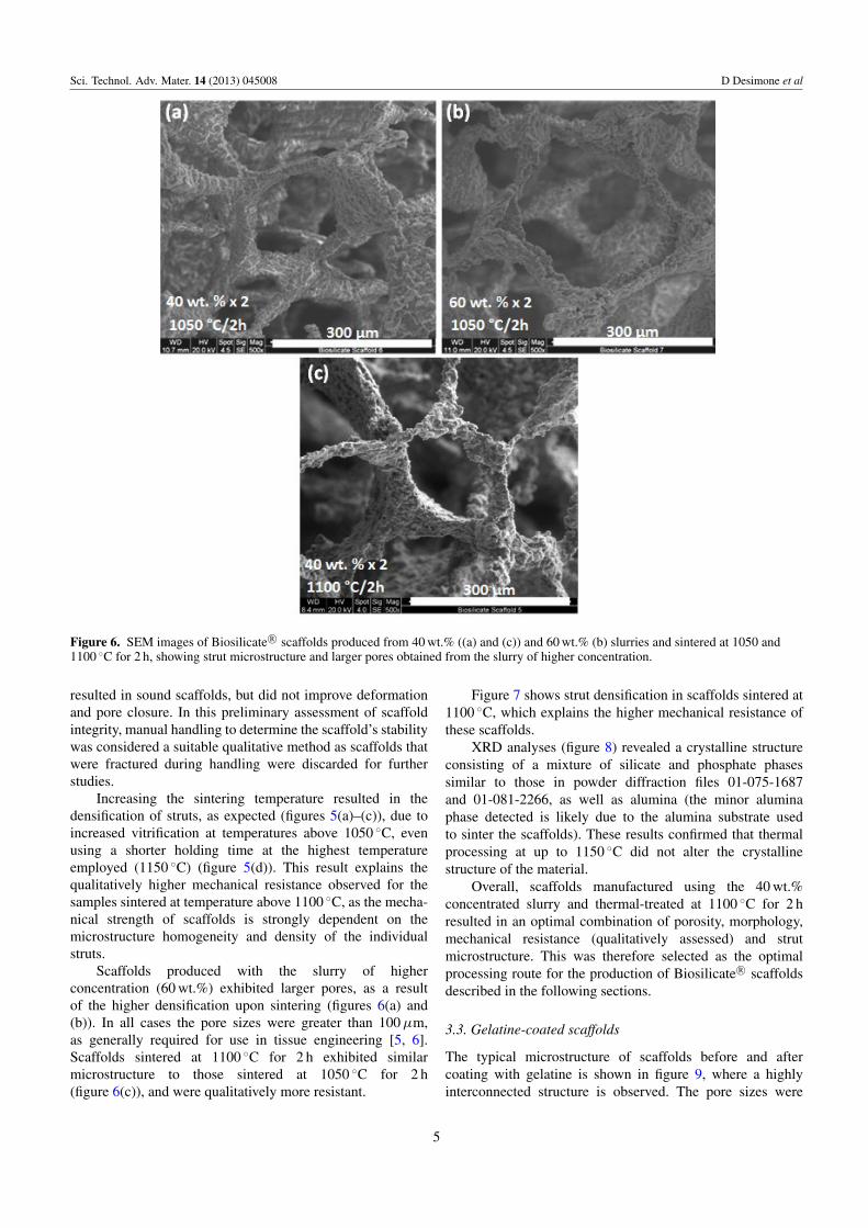
Figure 6. SEM images of Biosilicate R© scaffolds produced from 40 wt.% ((a) and (c)) and 60 wt.% (b) slurries and sintered at 1050 and1100 ◦C for 2 h, showing strut microstructure and larger pores obtained from the slurry of higher concentration.
resulted in sound scaffolds, but did not improve deformationand pore closure. In this preliminary assessment of scaffoldintegrity, manual handling to determine the scaffold’s stabilitywas considered a suitable qualitative method as scaffolds thatwere fractured during handling were discarded for furtherstudies.
Increasing the sintering temperature resulted in thedensification of struts, as expected (figures 5(a)–(c)), due toincreased vitrification at temperatures above 1050 ◦C, evenusing a shorter holding time at the highest temperatureemployed (1150 ◦C) (figure 5(d)). This result explains thequalitatively higher mechanical resistance observed for thesamples sintered at temperature above 1100 ◦C, as the mecha-nical strength of scaffolds is strongly dependent on themicrostructure homogeneity and density of the individualstruts.
Scaffolds produced with the slurry of higherconcentration (60 wt.%) exhibited larger pores, as a resultof the higher densification upon sintering (figures 6(a) and(b)). In all cases the pore sizes were greater than 100 µm,as generally required for use in tissue engineering [5, 6].Scaffolds sintered at 1100 ◦C for 2 h exhibited similarmicrostructure to those sintered at 1050 ◦C for 2 h(figure 6(c)), and were qualitatively more resistant.
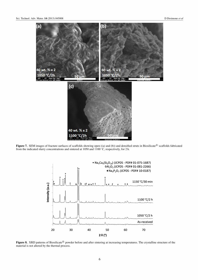
Figure 7 shows strut densification in scaffolds sintered at1100 ◦C, which explains the higher mechanical resistance ofthese scaffolds.
XRD analyses (figure 8) revealed a crystalline structureconsisting of a mixture of silicate and phosphate phasessimilar to those in powder diffraction files 01-075-1687and 01-081-2266, as well as alumina (the minor aluminaphase detected is likely due to the alumina substrate usedto sinter the scaffolds). These results confirmed that thermalprocessing at up to 1150 ◦C did not alter the crystallinestructure of the material.
Overall, scaffolds manufactured using the 40 wt.%concentrated slurry and thermal-treated at 1100 ◦C for 2 hresulted in an optimal combination of porosity, morphology,mechanical resistance (qualitatively assessed) and strutmicrostructure. This was therefore selected as the optimalprocessing route for the production of Biosilicate R© scaffoldsdescribed in the following sections.
3.3. Gelatine-coated scaffolds
The typical microstructure of scaffolds before and aftercoating with gelatine is shown in figure 9, where a highlyinterconnected structure is observed. The pore sizes were
5
Sci. Technol. Adv. Mater. 14 (2013) 045008 D Desimone et al
Figure 7. SEM images of fracture surfaces of scaffolds showing open ((a) and (b)) and densified struts in Biosilicate R© scaffolds fabricatedfrom the indicated slurry concentrations and sintered at 1050 and 1100 ◦C, respectively, for 2 h.
Figure 8. XRD patterns of Biosilicate R© powder before and after sintering at increasing temperatures. The crystalline structure of thematerial is not altered by the thermal process.
6
Sci. Technol. Adv. Mater. 14 (2013) 045008 D Desimone et al
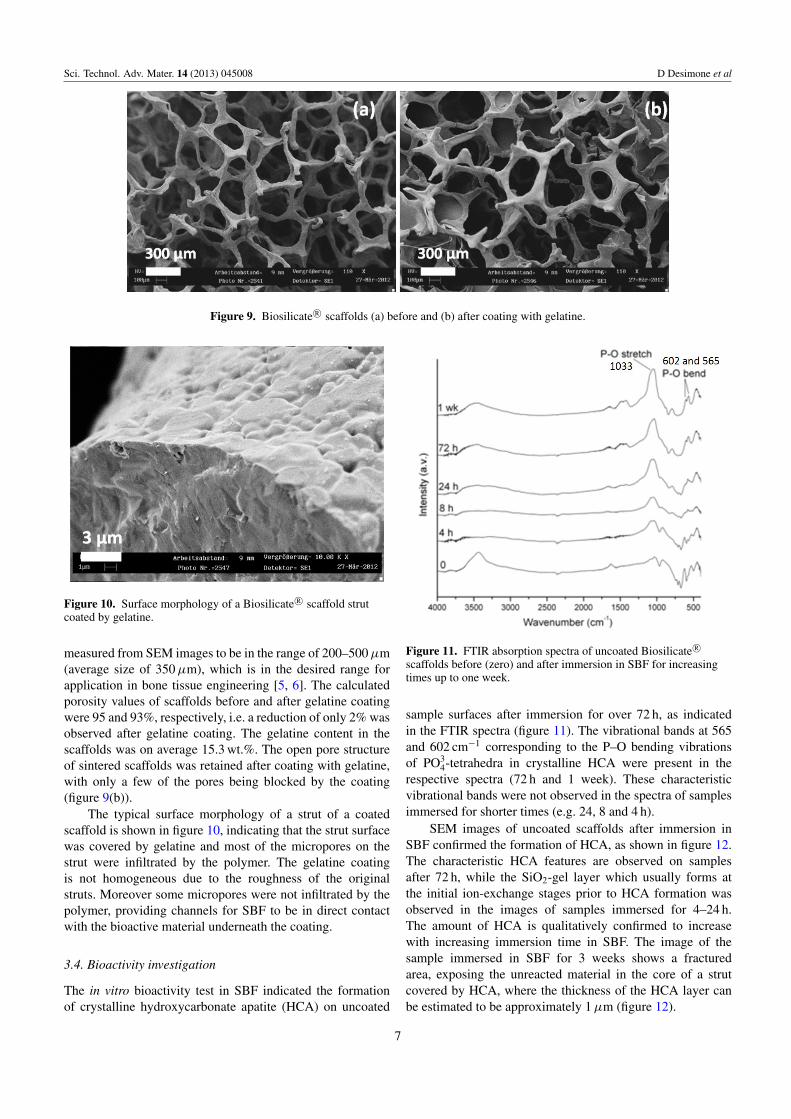
Figure 9. Biosilicate R© scaffolds (a) before and (b) after coating with gelatine.
Figure 10. Surface morphology of a Biosilicate R© scaffold strutcoated by gelatine.
measured from SEM images to be in the range of 200–500 µm(average size of 350 µm), which is in the desired range forapplication in bone tissue engineering [5, 6]. The calculatedporosity values of scaffolds before and after gelatine coatingwere 95 and 93%, respectively, i.e. a reduction of only 2% wasobserved after gelatine coating. The gelatine content in thescaffolds was on average 15.3 wt.%. The open pore structureof sintered scaffolds was retained after coating with gelatine,with only a few of the pores being blocked by the coating(figure 9(b)).
The typical surface morphology of a strut of a coatedscaffold is shown in figure 10, indicating that the strut surfacewas covered by gelatine and most of the micropores on thestrut were infiltrated by the polymer. The gelatine coatingis not homogeneous due to the roughness of the originalstruts. Moreover some micropores were not infiltrated by thepolymer, providing channels for SBF to be in direct contactwith the bioactive material underneath the coating.
3.4. Bioactivity investigation
The in vitro bioactivity test in SBF indicated the formationof crystalline hydroxycarbonate apatite (HCA) on uncoated
Figure 11. FTIR absorption spectra of uncoated Biosilicate R©
scaffolds before (zero) and after immersion in SBF for increasingtimes up to one week.
sample surfaces after immersion for over 72 h, as indicatedin the FTIR spectra (figure 11). The vibrational bands at 565and 602 cm−1 corresponding to the P–O bending vibrationsof PO3
4-tetrahedra in crystalline HCA were present in therespective spectra (72 h and 1 week). These characteristicvibrational bands were not observed in the spectra of samplesimmersed for shorter times (e.g. 24, 8 and 4 h).
SEM images of uncoated scaffolds after immersion inSBF confirmed the formation of HCA, as shown in figure 12.The characteristic HCA features are observed on samplesafter 72 h, while the SiO2-gel layer which usually forms atthe initial ion-exchange stages prior to HCA formation wasobserved in the images of samples immersed for 4–24 h.The amount of HCA is qualitatively confirmed to increasewith increasing immersion time in SBF. The image of thesample immersed in SBF for 3 weeks shows a fracturedarea, exposing the unreacted material in the core of a strutcovered by HCA, where the thickness of the HCA layer canbe estimated to be approximately 1 µm (figure 12).
7
Sci. Technol. Adv. Mater. 14 (2013) 045008 D Desimone et al
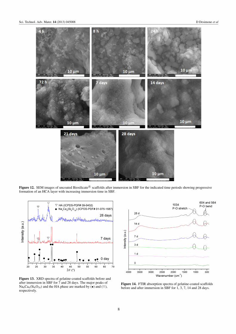
Figure 12. SEM images of uncoated Biosilicate R© scaffolds after immersion in SBF for the indicated time periods showing progressiveformation of an HCA layer with increasing immersion time in SBF.
Figure 13. XRD spectra of gelatine-coated scaffolds before andafter immersion in SBF for 7 and 28 days. The major peaks ofNa4Ca4(Si6O18) and the HA phase are marked by (•) and (O),respectively.
Figure 14. FTIR absorption spectra of gelatine-coated scaffoldsbefore and after immersion in SBF for 1, 3, 7, 14 and 28 days.
8
Sci. Technol. Adv. Mater. 14 (2013) 045008 D Desimone et al
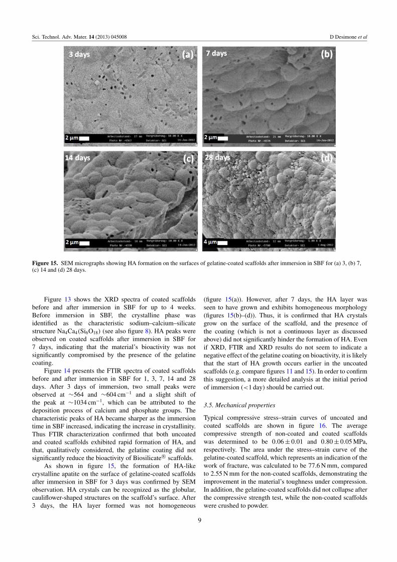
Figure 15. SEM micrographs showing HA formation on the surfaces of gelatine-coated scaffolds after immersion in SBF for (a) 3, (b) 7,(c) 14 and (d) 28 days.
Figure 13 shows the XRD spectra of coated scaffoldsbefore and after immersion in SBF for up to 4 weeks.Before immersion in SBF, the crystalline phase wasidentified as the characteristic sodium–calcium–silicatestructure Na4Ca4(Si6O18) (see also figure 8). HA peaks wereobserved on coated scaffolds after immersion in SBF for7 days, indicating that the material’s bioactivity was notsignificantly compromised by the presence of the gelatinecoating.
Figure 14 presents the FTIR spectra of coated scaffoldsbefore and after immersion in SBF for 1, 3, 7, 14 and 28days. After 3 days of immersion, two small peaks wereobserved at ∼564 and ∼604 cm−1 and a slight shift ofthe peak at ∼1034 cm−1, which can be attributed to thedeposition process of calcium and phosphate groups. Thecharacteristic peaks of HA became sharper as the immersiontime in SBF increased, indicating the increase in crystallinity.Thus FTIR characterization confirmed that both uncoatedand coated scaffolds exhibited rapid formation of HA, andthat, qualitatively considered, the gelatine coating did notsignificantly reduce the bioactivity of Biosilicate R© scaffolds.
As shown in figure 15, the formation of HA-likecrystalline apatite on the surface of gelatine-coated scaffoldsafter immersion in SBF for 3 days was confirmed by SEMobservation. HA crystals can be recognized as the globular,cauliflower-shaped structures on the scaffold’s surface. After3 days, the HA layer formed was not homogeneous
(figure 15(a)). However, after 7 days, the HA layer wasseen to have grown and exhibits homogeneous morphology(figures 15(b)–(d)). Thus, it is confirmed that HA crystalsgrow on the surface of the scaffold, and the presence ofthe coating (which is not a continuous layer as discussedabove) did not significantly hinder the formation of HA. Evenif XRD, FTIR and XRD results do not seem to indicate anegative effect of the gelatine coating on bioactivity, it is likelythat the start of HA growth occurs earlier in the uncoatedscaffolds (e.g. compare figures 11 and 15). In order to confirmthis suggestion, a more detailed analysis at the initial periodof immersion (<1 day) should be carried out.
3.5. Mechanical properties
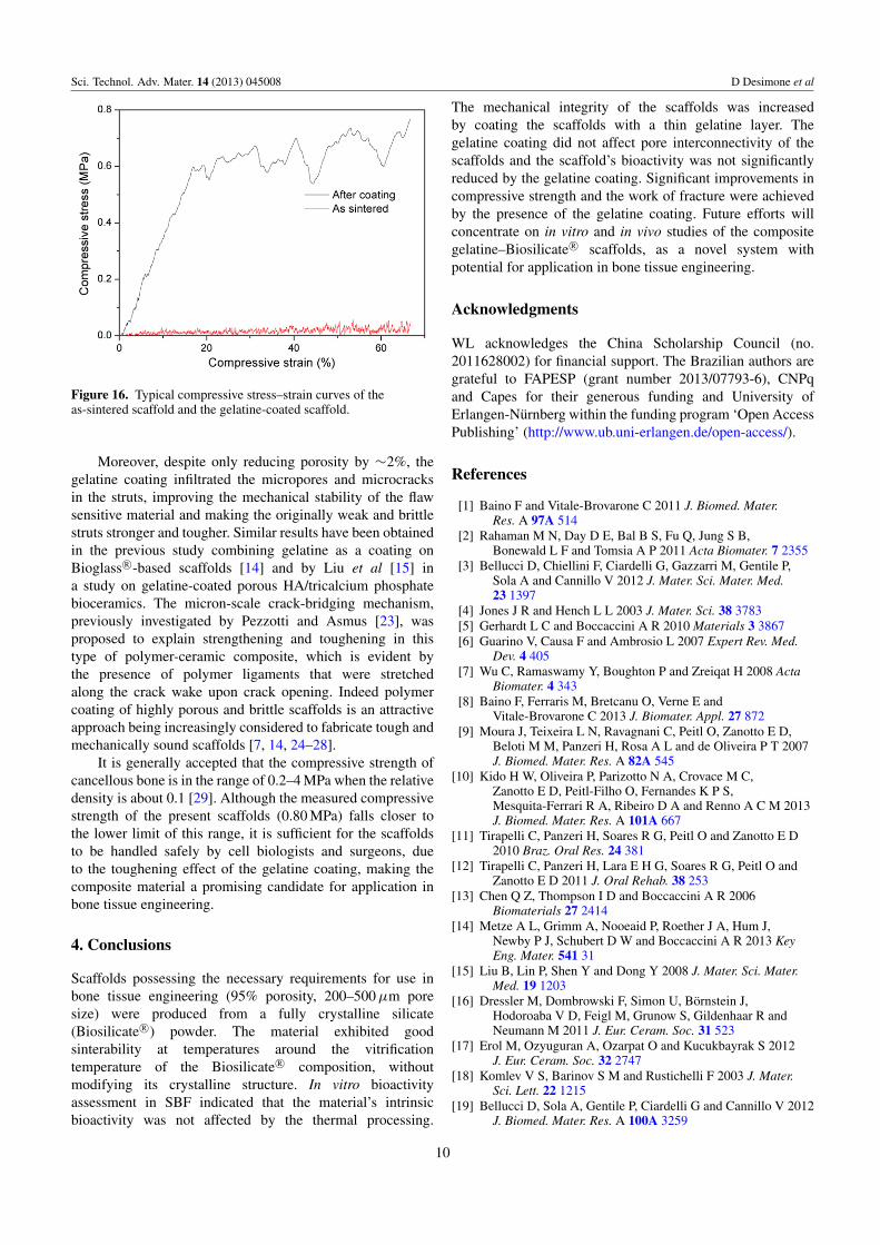
Typical compressive stress–strain curves of uncoated andcoated scaffolds are shown in figure 16. The averagecompressive strength of non-coated and coated scaffoldswas determined to be 0.06 ± 0.01 and 0.80 ± 0.05 MPa,respectively. The area under the stress–strain curve of thegelatine-coated scaffold, which represents an indication of thework of fracture, was calculated to be 77.6 N mm, comparedto 2.55 N mm for the non-coated scaffolds, demonstrating theimprovement in the material’s toughness under compression.In addition, the gelatine-coated scaffolds did not collapse afterthe compressive strength test, while the non-coated scaffoldswere crushed to powder.
9
Sci. Technol. Adv. Mater. 14 (2013) 045008 D Desimone et al
Figure 16. Typical compressive stress–strain curves of theas-sintered scaffold and the gelatine-coated scaffold.
Moreover, despite only reducing porosity by ∼2%, thegelatine coating infiltrated the micropores and microcracksin the struts, improving the mechanical stability of the flawsensitive material and making the originally weak and brittlestruts stronger and tougher. Similar results have been obtainedin the previous study combining gelatine as a coating onBioglass R©-based scaffolds [14] and by Liu et al [15] ina study on gelatine-coated porous HA/tricalcium phosphatebioceramics. The micron-scale crack-bridging mechanism,previously investigated by Pezzotti and Asmus [23], wasproposed to explain strengthening and toughening in thistype of polymer-ceramic composite, which is evident bythe presence of polymer ligaments that were stretchedalong the crack wake upon crack opening. Indeed polymercoating of highly porous and brittle scaffolds is an attractiveapproach being increasingly considered to fabricate tough andmechanically sound scaffolds [7, 14, 24–28].
It is generally accepted that the compressive strength ofcancellous bone is in the range of 0.2–4 MPa when the relativedensity is about 0.1 [29]. Although the measured compressivestrength of the present scaffolds (0.80 MPa) falls closer tothe lower limit of this range, it is sufficient for the scaffoldsto be handled safely by cell biologists and surgeons, dueto the toughening effect of the gelatine coating, making thecomposite material a promising candidate for application inbone tissue engineering.
4. Conclusions
Scaffolds possessing the necessary requirements for use inbone tissue engineering (95% porosity, 200–500 µm poresize) were produced from a fully crystalline silicate(Biosilicate R©) powder. The material exhibited goodsinterability at temperatures around the vitrificationtemperature of the Biosilicate R© composition, withoutmodifying its crystalline structure. In vitro bioactivityassessment in SBF indicated that the material’s intrinsicbioactivity was not affected by the thermal processing.
The mechanical integrity of the scaffolds was increasedby coating the scaffolds with a thin gelatine layer. Thegelatine coating did not affect pore interconnectivity of thescaffolds and the scaffold’s bioactivity was not significantlyreduced by the gelatine coating. Significant improvements incompressive strength and the work of fracture were achievedby the presence of the gelatine coating. Future efforts willconcentrate on in vitro and in vivo studies of the compositegelatine–Biosilicate R© scaffolds, as a novel system withpotential for application in bone tissue engineering.
Acknowledgments
WL acknowledges the China Scholarship Council (no.2011628002) for financial support. The Brazilian authors aregrateful to FAPESP (grant number 2013/07793-6), CNPqand Capes for their generous funding and University ofErlangen-Nurnberg within the funding program ‘Open AccessPublishing’ (http://www.ub.uni-erlangen.de/open-access/).
References
[1] Baino F and Vitale-Brovarone C 2011 J. Biomed. Mater.Res. A 97A 514
[2] Rahaman M N, Day D E, Bal B S, Fu Q, Jung S B,Bonewald L F and Tomsia A P 2011 Acta Biomater. 7 2355
[3] Bellucci D, Chiellini F, Ciardelli G, Gazzarri M, Gentile P,Sola A and Cannillo V 2012 J. Mater. Sci. Mater. Med.23 1397
[4] Jones J R and Hench L L 2003 J. Mater. Sci. 38 3783[5] Gerhardt L C and Boccaccini A R 2010 Materials 3 3867[6] Guarino V, Causa F and Ambrosio L 2007 Expert Rev. Med.
Dev. 4 405[7] Wu C, Ramaswamy Y, Boughton P and Zreiqat H 2008 Acta
Biomater. 4 343[8] Baino F, Ferraris M, Bretcanu O, Verne E and
Vitale-Brovarone C 2013 J. Biomater. Appl. 27 872[9] Moura J, Teixeira L N, Ravagnani C, Peitl O, Zanotto E D,
Beloti M M, Panzeri H, Rosa A L and de Oliveira P T 2007J. Biomed. Mater. Res. A 82A 545
[10] Kido H W, Oliveira P, Parizotto N A, Crovace M C,Zanotto E D, Peitl-Filho O, Fernandes K P S,Mesquita-Ferrari R A, Ribeiro D A and Renno A C M 2013J. Biomed. Mater. Res. A 101A 667
[11] Tirapelli C, Panzeri H, Soares R G, Peitl O and Zanotto E D2010 Braz. Oral Res. 24 381
[12] Tirapelli C, Panzeri H, Lara E H G, Soares R G, Peitl O andZanotto E D 2011 J. Oral Rehab. 38 253
[13] Chen Q Z, Thompson I D and Boccaccini A R 2006Biomaterials 27 2414
[14] Metze A L, Grimm A, Nooeaid P, Roether J A, Hum J,Newby P J, Schubert D W and Boccaccini A R 2013 KeyEng. Mater. 541 31
[15] Liu B, Lin P, Shen Y and Dong Y 2008 J. Mater. Sci. Mater.Med. 19 1203
[16] Dressler M, Dombrowski F, Simon U, Bornstein J,Hodoroaba V D, Feigl M, Grunow S, Gildenhaar R andNeumann M 2011 J. Eur. Ceram. Soc. 31 523
[17] Erol M, Ozyuguran A, Ozarpat O and Kucukbayrak S 2012J. Eur. Ceram. Soc. 32 2747
[18] Komlev V S, Barinov S M and Rustichelli F 2003 J. Mater.Sci. Lett. 22 1215
[19] Bellucci D, Sola A, Gentile P, Ciardelli G and Cannillo V 2012J. Biomed. Mater. Res. A 100A 3259
10
Sci. Technol. Adv. Mater. 14 (2013) 045008 D Desimone et al
[20] Boccaccini A R, Stumpfe W, Taplin D M R and Ponton C B1996 Mater. Sci. Eng. A Struct. Mater. 219 26
[21] Newby P 2013 PhD Thesis Department of Materials ImperialCollege, London
[22] Kokubo T, Ito S, Huang Z, Hayashi T, Sakka S, Kitsugi T andYamamuro T 1990 J. Biomed. Mater. Res. 24 331
[23] Pezzotti G and Asmus S M F 2001 Mater. Sci. Eng. A Struct.Mater. 316 231
[24] Yunos D M, Bretcanu O and Boccaccini A R 2008 J. Mater.Sci. 43 4433
[25] Peroglio M, Gremillard L, Chevalier J, Chazeau L, Gauthier Cand Hamaide T 2007 J. Eur. Ceram. Soc. 27 2679
[26] Kim H W, Knowles J C and Kim H E 2004 Biomaterials25 1279
[27] Nie L, Chen D, Yang Q, Zou P, Feng S, Hu H and Suo J 2013Mater. Lett. 92 25
[28] Yang G, Yang X, Zhang L, Lin M, Sun X, Chen X and Gou Z2012 Mater. Lett. 75 80
[29] Gibson L J and Ashby M F 1999 Cellular Solids: Structureand Properties (Cambridge: Cambridge University Press)
11


![Il CEO di Rhino Reg Clark con il Tour Manager John Spencer … · Replica Misura 4 [BIREP-4] Replica Misura 3 [BIREP-3] Replica Midi [BIREP-MIDI] Replica Mini [BIREP-MINI] Replica](https://static.cupdf.com/doc/110x72/603b370a8bb50a7da63bf8e1/il-ceo-di-rhino-reg-clark-con-il-tour-manager-john-spencer-replica-misura-4-birep-4.jpg)