Post-processing of polymer foam tissue scaffolds with high power ultrasound: a route to increased pore interconnectivity, pore size and fluid transport N J Watson 1 , R K Johal 2 , Y Reinwald 3 , L J White 3 ,AM Ghaemmaghami 2 , S P Morgan 4 , F R A J Rose 3 , M J W Povey 1 and N G Parker 1,5 1 School of Food Science and Nutrition, University of Leeds, Leeds, LS2 9JT, UK 2 Division of Immunology, School of Molecular Medical Sciences, Queen’s Medical Centre, University of Nottingham, Nottingham, NG7 2UH, UK 3 School of Pharmacy, Centre for Biomolecular Sciences, University of Nottingham, Nottingham, NG7 2RD, UK 4 Electrical Systems and Optics Research Division, Faculty of Engineering, University of Nottingham, Nottingham, NG7 2RD, UK 5 School of Mathematics and Statistics, Newcastle University, Newcastle upon Tyne, NE1 7RU, UK E-mail: [email protected] Abstract. We expose thick polymer foam tissue scaffolds to high power ultrasound and study its effect on the openness of the pore architecture and fluid transport through the scaffold. Our analysis is supported by measurements of fluid uptake during insonification and imaging of the scaffold microstructure via x-ray computed tomography, scanning electron microscopy and acoustic microscopy. The ultrasonic treatment is found to increase the mean pore size by over 10%. More striking is the improvement in fluid uptake: for scaffolds with only 40% water uptake via standard immersion techniques, we can routinely achieve full saturation of the scaffold over approximately one hour of exposure. These desirable modifications occur with no loss of scaffold integrity and negligible mass loss, and are optimized when the ultrasound treatment is coupled to a pre-wetting stage with ethanol. Our findings suggest that high power ultrasound is a highly targetted and efficient means to promote pore interconnectivity and fluid transport in thick foam tissue scaffolds.

Welcome message from author
This document is posted to help you gain knowledge. Please leave a comment to let me know what you think about it! Share it to your friends and learn new things together.
Transcript
Post-processing of polymer foam tissue scaffolds
with high power ultrasound: a route to increased
pore interconnectivity, pore size and fluid transport
N J Watson1, R K Johal2, Y Reinwald3, L J White3, A M
Ghaemmaghami2, S P Morgan4, F R A J Rose3, M J W Povey1
and N G Parker1,5
1School of Food Science and Nutrition, University of Leeds, Leeds, LS2 9JT, UK2Division of Immunology, School of Molecular Medical Sciences, Queen’s Medical
Centre, University of Nottingham, Nottingham, NG7 2UH, UK3School of Pharmacy, Centre for Biomolecular Sciences, University of Nottingham,
Nottingham, NG7 2RD, UK4 Electrical Systems and Optics Research Division, Faculty of Engineering, University
of Nottingham, Nottingham, NG7 2RD, UK5 School of Mathematics and Statistics, Newcastle University, Newcastle upon Tyne,
NE1 7RU, UK
E-mail: [email protected]
Abstract. We expose thick polymer foam tissue scaffolds to high power ultrasound
and study its effect on the openness of the pore architecture and fluid transport
through the scaffold. Our analysis is supported by measurements of fluid uptake
during insonification and imaging of the scaffold microstructure via x-ray computed
tomography, scanning electron microscopy and acoustic microscopy. The ultrasonic
treatment is found to increase the mean pore size by over 10%. More striking is the
improvement in fluid uptake: for scaffolds with only 40% water uptake via standard
immersion techniques, we can routinely achieve full saturation of the scaffold over
approximately one hour of exposure. These desirable modifications occur with no loss
of scaffold integrity and negligible mass loss, and are optimized when the ultrasound
treatment is coupled to a pre-wetting stage with ethanol. Our findings suggest that
high power ultrasound is a highly targetted and efficient means to promote pore
interconnectivity and fluid transport in thick foam tissue scaffolds.
Post-processing of polymer foam tissue scaffolds with high power ultrasound 2
1. Introduction
Biodegradable polymer foams are of major interest as three-dimensional scaffolds for
tissue engineering [1]. A three-dimensional pore structure provides a high surface area
for cell adhesion, while biodegradation leads to the gradual removal of the artificial
scaffold as the native extracellular matrix develops. In such structures, an open pore
structure is essential to promote homogeneous tissue growth and efficient transport of
waste and nutrients.
The synthetic polymer poly(lactic acid) (PLA) is commonly used for such
scaffolds due to its economy, structural versatility, well characterized and tuneable
biodegradation, and its long history of use in the clinic [2]. Conventional solid
state foaming techniques based on gas blowing are not directly tractable for scaffold
fabrication since they lead to a closed pore structure. As such, a raft of other techniques
have been developed to generate a more open pore architecture, for example, solvent
casting/particulate leaching, emulsification/freeze-drying, phase separation, 3D printing
(see [3] for a review of these methods) and supercritical CO2 foaming [4]. Each method
has its own merits and limitations in terms of the level of pore connectivity produced, the
control over the pore size, the involvement of organic solvents, and the overall economy
and efficiency. We will consider scaffolds formed by the supercritical CO2 method. This
method produces scaffolds with a relatively interconnected, open-cell structure with
the advantage that this can be achieved using relatively low temperatures and without
organic solvents [5]. These merits make these scaffolds amenable to the incorporation
of biological materials such as growth factors [6] and even mammalian cells [7].
The use of post-processing techniques to further engineer the structural properties of
these foams would strongly support these methods, for example, to further improve the
pore connectivity and fluid transport (essential for cell ingress and nutrient perfusion), or
to provide a level of fine-tuning the structure towards individual cell and tissue types. A
further challenge posed by PLA-based scaffolds is the polymer’s hydrophobicitiy which
strongly inhibits the uptake of water-based fluids, such as cell culture media. The use
of a pre-wetting stage with ethanol has been shown to enhance the final uptake of water
into hydrophobic scaffolds [8]. Further strategies to overcome the hydrophobicity and
improve cell penetration within these polymers include the use of suitable co-polymers
[9] and surface coatings [10].
High power ultrasound finds diverse applications, from cleaning and homogenizing
to chemical synthesis to sterilization [11, 12]. High power ultrasound refers to sound
waves in the ultrasonic range (frequencies greater than approximately 20 kHz) that are
of high power (typically 50 W and above). These waves generate intense local agitation
of the ambient fluid. Mostly this occurs through cavitating bubbles which collapse and
generate intense pressure and temperatures on the micro-scale. The ability of high power
ultrasound to open up the scaffold structure was first demonstrated by Wang et al [13].
There, exposure of 3D scaffolds with initially closed pore structure, formed via solid state
foaming, to high power ultrasound led to a marked increase in pore interconnectivity
Post-processing of polymer foam tissue scaffolds with high power ultrasound 3
and generation of an open pore structure. This work was extended in Ref. [14] where
it was found that the enhancement in pore interconnectivity and permeability increases
with temperature, pore size and ultrasound power. Guo et al. [15] applied high power
ultrasound to solid-state fabricated PLA foamed sheets and noted a similar increase in
pore interconnectivity. Lee et al. [16] exposed thin electrospun scaffolds composed of
PLLA to high power ultrasound and observed around a 15% increase in porosity. This
study went on to seed cells on the scaffolds and observed the cell infilitration to increase
strongly in insonified scaffolds.
Here we further examine the capacity of high power ultrasound to modify the
internal structure and transport properties of thick foam polymer scaffolds. Where
Wang et al [13, 14] and Guo et al [15] considered solid-state foams, our focus is on
scaffolds formed via supercritical CO2 foaming. This type of scaffold is at a more
advanced stage in biomedical research, having successfuly demonstrated the controlled
release of proteins [17] and [18], incorporation of mammalian cells [7], promotion of
bone formation [19] and the induction of angiogenesis in vitro [20]. The modification of
scaffold structure is analysed via micro x-ray computed tomography, scanning electron
microscopy and acoustic microscopy. We pay particular attention to how insonification
improves fluid transport through the scaffold, of essential importance for cell infusion
and during tissue growth, by monitoring the uptake of water into the scaffold. The effect
of pre-wetting the scaffold with ethanol (a means to aid overcoming the hydrophobicity
of PLA) is also studied.
2. Materials and methods
2.1. PLA scaffolds formed via supercritical CO2 foaming
The scaffolds were composed of PLA (Purac, Gorinchem, Netherlands), with a density
of 1200 kg m−3 (manufacturer’s specification) and molecular weight (weight averaged) of
55 kDa (determined in our laboratories via NMR). The foamed scaffolds were fabricated
using the supercritical CO2 method as detailed in [5]. In brief, granular polymer was
weighed into each well of a Teflon multi-well mould. The mould was placed inside a 60 ml
high pressure autoclave which was heated to, and maintained at, 35oC. Compressed CO2
is then introduced, maintaining a pressure of 230 bar. The vessel was later depressurized
(at a constant rate) to ambient pressure. The porous scaffolds fabricated had diameters
of approximately 10 mm and were 5–10 mm in height. A non-porous skin was removed
by a scalpel blade prior to immersion and ultrasound treatment.
2.2. Scafffold immersion and treatment
Each scaffold was immersed in approximately 3 cm of liquid (water or ethanol) within
a test-tube and weighed down (since the scaffold is initially buoyant) by a piece of
rubber tubing. The test tube was cooled in a water-bath maintained at 5oC to avoid
reaching the glass transition temperature of the polymer. The natural glass transition
Post-processing of polymer foam tissue scaffolds with high power ultrasound 4
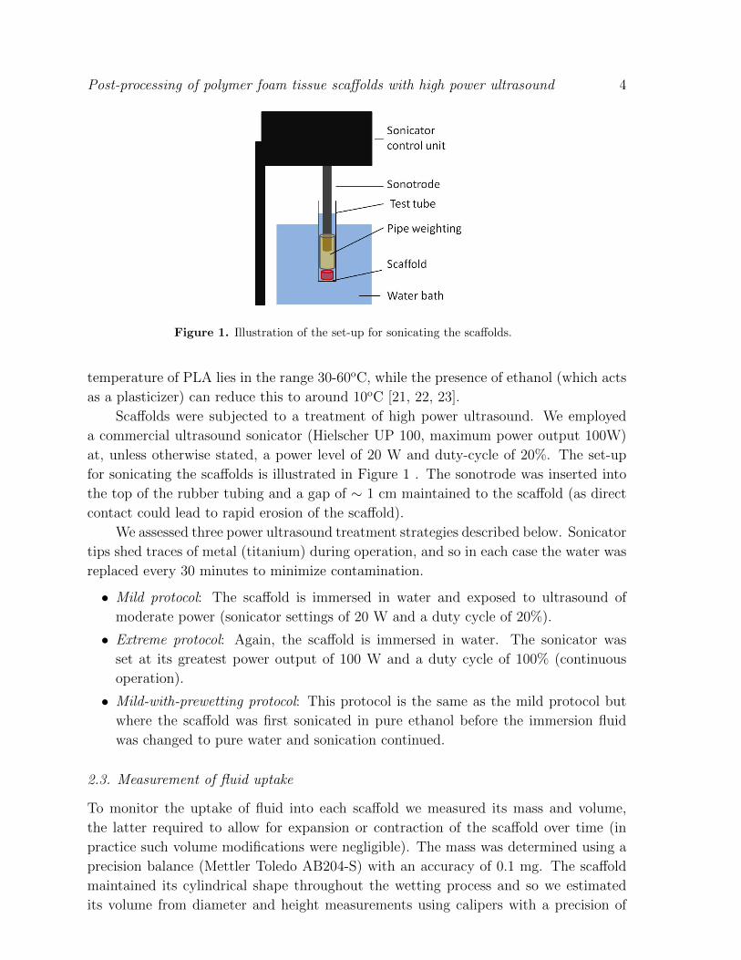
Figure 1. Illustration of the set-up for sonicating the scaffolds.
temperature of PLA lies in the range 30-60oC, while the presence of ethanol (which acts
as a plasticizer) can reduce this to around 10oC [21, 22, 23].
Scaffolds were subjected to a treatment of high power ultrasound. We employed
a commercial ultrasound sonicator (Hielscher UP 100, maximum power output 100W)
at, unless otherwise stated, a power level of 20 W and duty-cycle of 20%. The set-up
for sonicating the scaffolds is illustrated in Figure 1 . The sonotrode was inserted into
the top of the rubber tubing and a gap of ∼ 1 cm maintained to the scaffold (as direct
contact could lead to rapid erosion of the scaffold).
We assessed three power ultrasound treatment strategies described below. Sonicator
tips shed traces of metal (titanium) during operation, and so in each case the water was
replaced every 30 minutes to minimize contamination.
• Mild protocol: The scaffold is immersed in water and exposed to ultrasound of
moderate power (sonicator settings of 20 W and a duty cycle of 20%).
• Extreme protocol: Again, the scaffold is immersed in water. The sonicator was
set at its greatest power output of 100 W and a duty cycle of 100% (continuous
operation).
• Mild-with-prewetting protocol: This protocol is the same as the mild protocol but
where the scaffold was first sonicated in pure ethanol before the immersion fluid
was changed to pure water and sonication continued.
2.3. Measurement of fluid uptake
To monitor the uptake of fluid into each scaffold we measured its mass and volume,
the latter required to allow for expansion or contraction of the scaffold over time (in
practice such volume modifications were negligible). The mass was determined using a
precision balance (Mettler Toledo AB204-S) with an accuracy of 0.1 mg. The scaffold
maintained its cylindrical shape throughout the wetting process and so we estimated
its volume from diameter and height measurements using calipers with a precision of

Post-processing of polymer foam tissue scaffolds with high power ultrasound 5
10 µm. Finally, the scaffolds were air-dried and weighed so as to assess any mass loss
during the ultrasonic treatment.
2.4. Filling fraction
To monitor the filling of the scaffold pores with fluid during immersion we define a filling
fraction F (t),
F (t) =Vfluid(t)
Vpore(t), (1)
where Vfluid(t) and Vpore(t) are the volumes of fluid and pore space, respectively, within
the scaffold. F = 0 corresponds to when the scaffold is free from fluid; F = 1
corresponds to complete saturation. We define t = 0 to be the start of the immersion,
i.e. F (t = 0) = 0. The fluid volume within the scaffold Vfluid(t) is derived from the
increase in total scaffold mass via Vfluid(t) = [mtot(t) − mtot(t = 0)]/ρfluid. We take
ρfluid = 998 kg m−3 for water and ρfluid = 789 kg m−3 for ethanol [24].
The pore volume is determined from Vpore(t) = Vtot(t) − Vframe, where we assume
the total volume to vary but the frame volume to be fixed (we will see that the
frame loss is small enough to be neglected). Combining these, and using the relation
Vframe = mtot(t = 0)/ρframe, we arrive at,
F (t) =ρframe
ρfluid
(mtot(t) −mtot(t = 0)
Vtot(t)ρframe −mtot(t = 0)
). (2)
In the two-stage (ethanol-then-water) wetting protocol, it was useful to follow the
replacement of ethanol by water. Assuming that the scaffold is completely saturated
with ethanol and that its total volume is fixed, then the fluid volume must constant and
any changes in the total scaffold mass must be due to a change in the density of the
fluid within. An expression for the time-dependent fluid density ρfluid(t) is obtained by
setting F = 1 in Equation (2) and rearranging,
ρfluid(t) = ρframe
(mtot(t) −mtot(t = 0)
Vtotρframe −mtot(t = 0)
). (3)
To monitor fluid uptake via these equations, the scaffolds were removed at regular time
intervals and their mass and dimensions recorded. Excess water bound to the scaffold
due to surface tension, as well as deviations of the scaffold from a cylindrical shape,
introduce systematic errors in F and ρfluid which may reach 3%.
2.5. Micro x-ray-computed tomography
Treated and control scaffolds were characterised by micro x-ray-computed tomography
(SkyScan 1174, SkyScan, Aartselaar, Belgium) so as to extract the mean pore size.
Measurements were obtained at a voltage of 50 kV, current of 800µA and voxel resolution
of 11.9µm. The transmission images were reconstructed using the SkyScan supplied
software (NRecon). The mean pore size was obtained using direct morphometric
calculations in the SkyScan CTAn software package.
Post-processing of polymer foam tissue scaffolds with high power ultrasound 6
2.6. Scanning electron microscopy
Treated and control scaffolds were dissected with a scalpel to reveal an inner surface
which was imaged using scanning electron microscopy (SEM; JEOL JMS-6060 LV, JEOL
Ltd., Welwyn Garden City, Hertfordshire, UK). The scaffolds were sputter coated with
a thin layer of gold (Balzers Union SCD 030, Balzers Union Ltd., Liechtenstein) before
being imaged (at 10kV) with the associated Smile View program (JEOL Ltd., Welwyn
Garden City, Hertfordshire, UK). This approach enabled detailed visual inspection of
the scaffold pore structure before and after ultrasound treatment.
2.7. Acoustic microscopy
Treated and control scaffolds were imaged via an in-house acoustic microscope [25] and
these images analysed to provide a measure of porosity. This approach was employed
as an additional means to characterize the pore structure, but also as a proof-of-
principle demonstration of acoustic propagation through the scaffold (made possible
by the high level of saturation achieved [23]). The microscope directs focussed pulses
of sound, through water, to the specimen and detects the time-gated, back scattered
signal, outputting a voltage trace. By moving the pulsing/receiving transducer unit
above the sample on a motorized position system, we obtained a 3D map of the back
scattered signal in the form of a voltage. The microscope operates at 100 MHz and has
a focal distance of 6 microns. The lateral and axial resolution are 25 and 40 microns,
respectively [25].
Each scaffold was dissected vertically to expose an internal surface. C-scan images
were taken on three 2mm-square regions of the exposed surface (located at the centre and
opposing sides of the exposed surface), with the focal plane of the microscope aligned
with the surface plane. The acoustic C-scans represent a two-dimensional map of pore
space (no reflection) versus frame (non-zero reflection).
We parameterized the local porosity via image analysis. C-scan images were
converted to a binary image by setting a threshold intensity (taken to be 0.1 times
the peak, as described in Appendix A). This separates regions of the image representing
frame (ascribed a value of 0) from those with of pore space (ascribed a value of 1). The
average image intensity then represents the ratio of pore area to non-pore area, denoted
2D porosity. Assuming that the pore structure is sufficiently isotropic and homogeneous
then the 2D porosity should map on to the 3D porosity.
3. Results
3.1. Fluid uptake
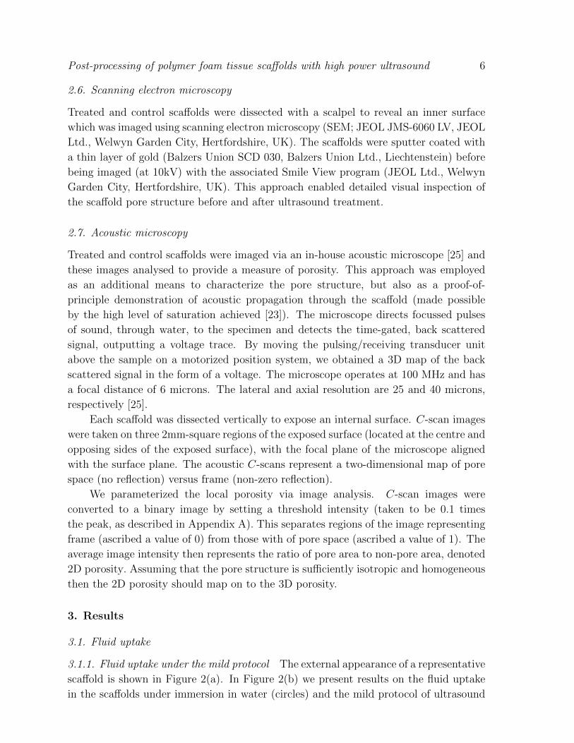
3.1.1. Fluid uptake under the mild protocol The external appearance of a representative
scaffold is shown in Figure 2(a). In Figure 2(b) we present results on the fluid uptake
in the scaffolds under immersion in water (circles) and the mild protocol of ultrasound
Post-processing of polymer foam tissue scaffolds with high power ultrasound 7
Figure 2. (a) Representative image of a supercritical CO2 fabricated scaffold. (b)
Water uptake in the scaffolds under immersion (circles) and immersion plus the
mild protocol of ultrasound (squares). Error bars represent standard deviation of
measurements on 4 scaffolds.
exposure (squares). Under immersion alone, the filling fraction saturates after several
hours to only (40 ± 4)%. Exposure to the mild protocol of ultrasound dramatically
improves the fluid uptake, which rises to approximately (83 ± 7)%. Incidentally,
exposure of the scaffolds to a standard laboratory sonic bath (data not presented) caused
little improvement in the filling fraction, indicating that the high power sonicator is
particularly effective for this purpose. However, this was still not sufficient to promote
full fluid uptake in the scaffolds.
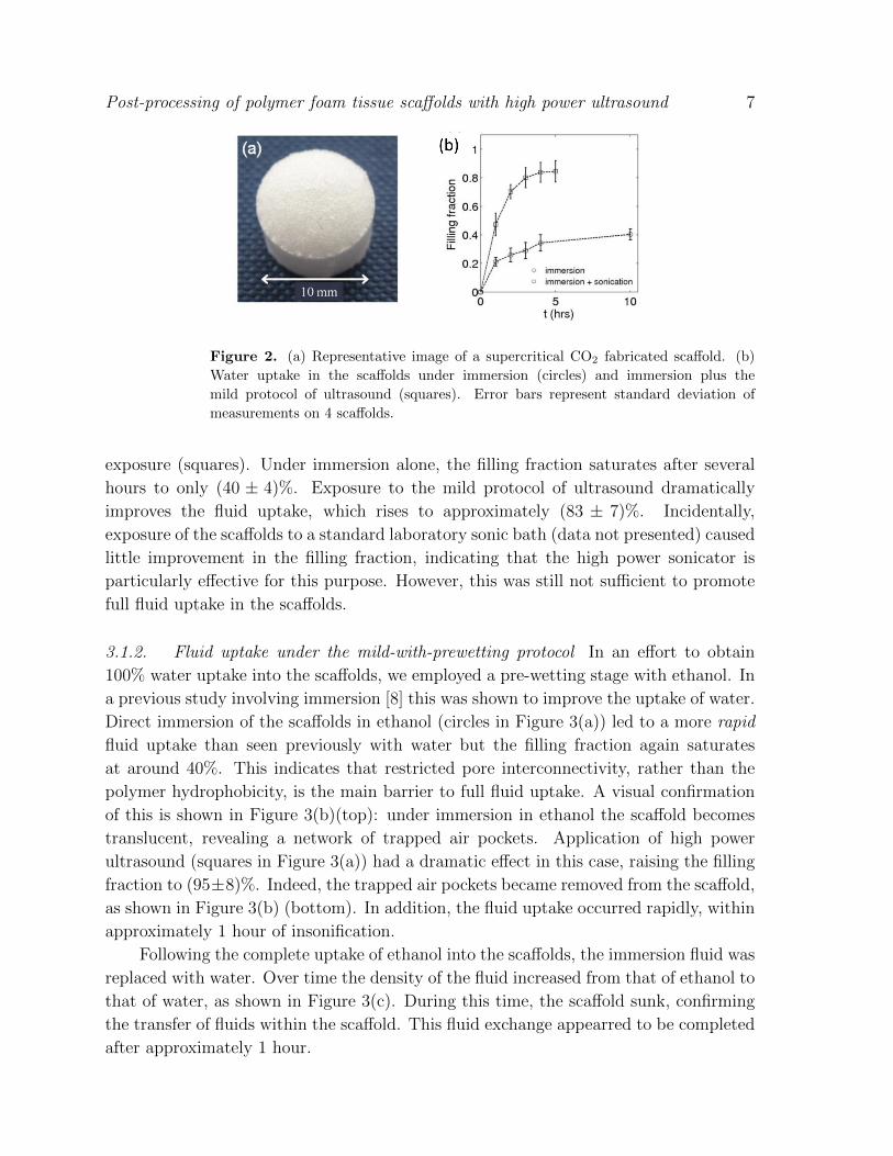
3.1.2. Fluid uptake under the mild-with-prewetting protocol In an effort to obtain
100% water uptake into the scaffolds, we employed a pre-wetting stage with ethanol. In
a previous study involving immersion [8] this was shown to improve the uptake of water.
Direct immersion of the scaffolds in ethanol (circles in Figure 3(a)) led to a more rapid
fluid uptake than seen previously with water but the filling fraction again saturates
at around 40%. This indicates that restricted pore interconnectivity, rather than the
polymer hydrophobicity, is the main barrier to full fluid uptake. A visual confirmation
of this is shown in Figure 3(b)(top): under immersion in ethanol the scaffold becomes
translucent, revealing a network of trapped air pockets. Application of high power
ultrasound (squares in Figure 3(a)) had a dramatic effect in this case, raising the filling
fraction to (95±8)%. Indeed, the trapped air pockets became removed from the scaffold,
as shown in Figure 3(b) (bottom). In addition, the fluid uptake occurred rapidly, within
approximately 1 hour of insonification.
Following the complete uptake of ethanol into the scaffolds, the immersion fluid was
replaced with water. Over time the density of the fluid increased from that of ethanol to
that of water, as shown in Figure 3(c). During this time, the scaffold sunk, confirming
the transfer of fluids within the scaffold. This fluid exchange appearred to be completed
after approximately 1 hour.
Post-processing of polymer foam tissue scaffolds with high power ultrasound 8
Mild-with-prewetting protocol Extreme protocol
Final filling fraction (%) 101 ± 3 87 ± 5
Average percentage mass loss (%) 0.6 1.9
Table 1. Scaffold characteristics after treatment with the mild-with-prewetting
protocol (2 hours in ethanol followed by 2 hours in water) and extreme protocol (10
hours in water). Data represents the mean and standard deviation of measurements
of 8 scafffolds.
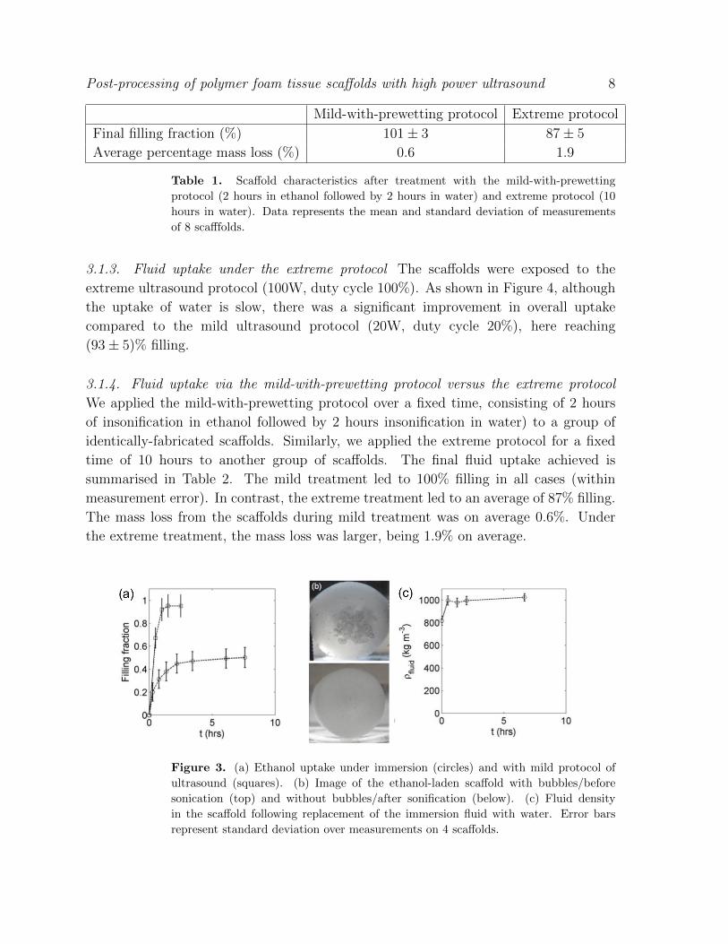
3.1.3. Fluid uptake under the extreme protocol The scaffolds were exposed to the
extreme ultrasound protocol (100W, duty cycle 100%). As shown in Figure 4, although
the uptake of water is slow, there was a significant improvement in overall uptake
compared to the mild ultrasound protocol (20W, duty cycle 20%), here reaching
(93 ± 5)% filling.
3.1.4. Fluid uptake via the mild-with-prewetting protocol versus the extreme protocol
We applied the mild-with-prewetting protocol over a fixed time, consisting of 2 hours
of insonification in ethanol followed by 2 hours insonification in water) to a group of
identically-fabricated scaffolds. Similarly, we applied the extreme protocol for a fixed
time of 10 hours to another group of scaffolds. The final fluid uptake achieved is
summarised in Table 2. The mild treatment led to 100% filling in all cases (within
measurement error). In contrast, the extreme treatment led to an average of 87% filling.
The mass loss from the scaffolds during mild treatment was on average 0.6%. Under
the extreme treatment, the mass loss was larger, being 1.9% on average.
Figure 3. (a) Ethanol uptake under immersion (circles) and with mild protocol of
ultrasound (squares). (b) Image of the ethanol-laden scaffold with bubbles/before
sonication (top) and without bubbles/after sonification (below). (c) Fluid density
in the scaffold following replacement of the immersion fluid with water. Error bars
represent standard deviation over measurements on 4 scaffolds.
Post-processing of polymer foam tissue scaffolds with high power ultrasound 9
Figure 4. Uptake of water under exposure to the extreme protocol of ultrasound.
Data represents the mean and standard deviation of measurements of 4 scafffolds.
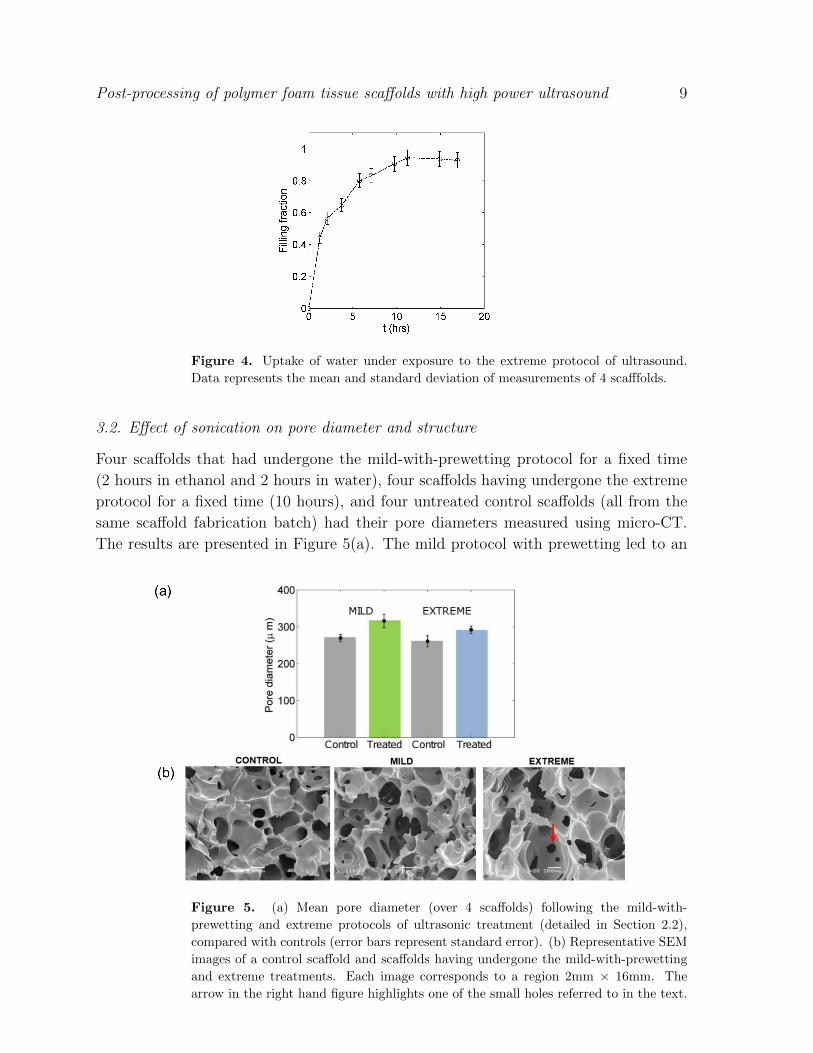
3.2. Effect of sonication on pore diameter and structure
Four scaffolds that had undergone the mild-with-prewetting protocol for a fixed time
(2 hours in ethanol and 2 hours in water), four scaffolds having undergone the extreme
protocol for a fixed time (10 hours), and four untreated control scaffolds (all from the
same scaffold fabrication batch) had their pore diameters measured using micro-CT.
The results are presented in Figure 5(a). The mild protocol with prewetting led to an
Figure 5. (a) Mean pore diameter (over 4 scaffolds) following the mild-with-
prewetting and extreme protocols of ultrasonic treatment (detailed in Section 2.2),
compared with controls (error bars represent standard error). (b) Representative SEM
images of a control scaffold and scaffolds having undergone the mild-with-prewetting
and extreme treatments. Each image corresponds to a region 2mm × 16mm. The
arrow in the right hand figure highlights one of the small holes referred to in the text.
Post-processing of polymer foam tissue scaffolds with high power ultrasound 10
increase in the average pore diameter from 270 to 315 µm (a 17% increase) whereas the
extreme protocol led to a change in average pore diameter from 261 to 292 µm (a 12%
increase). Figure 5(b) shows SEM images of the scaffolds. After mild treatment the
pore structure was more open than the control, with large sections of pore wall having
been removed. In contrast, extreme treatment maintains the same large-scale structure
as the control but with some small holes appearing in the pore walls.
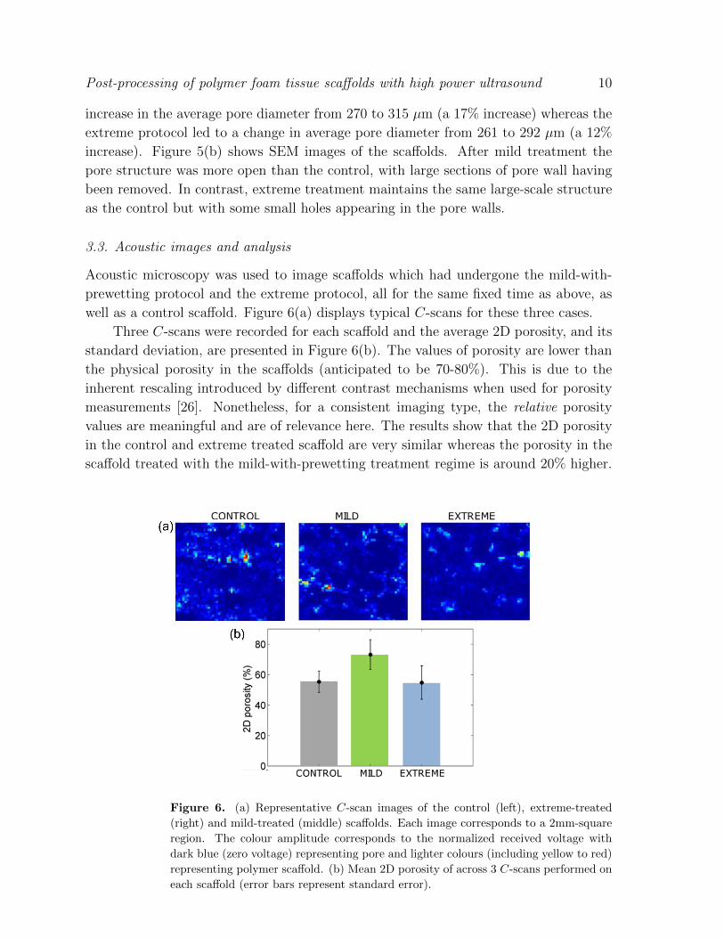
3.3. Acoustic images and analysis
Acoustic microscopy was used to image scaffolds which had undergone the mild-with-
prewetting protocol and the extreme protocol, all for the same fixed time as above, as
well as a control scaffold. Figure 6(a) displays typical C-scans for these three cases.
Three C-scans were recorded for each scaffold and the average 2D porosity, and its
standard deviation, are presented in Figure 6(b). The values of porosity are lower than
the physical porosity in the scaffolds (anticipated to be 70-80%). This is due to the
inherent rescaling introduced by different contrast mechanisms when used for porosity
measurements [26]. Nonetheless, for a consistent imaging type, the relative porosity
values are meaningful and are of relevance here. The results show that the 2D porosity
in the control and extreme treated scaffold are very similar whereas the porosity in the
scaffold treated with the mild-with-prewetting treatment regime is around 20% higher.
Figure 6. (a) Representative C-scan images of the control (left), extreme-treated
(right) and mild-treated (middle) scaffolds. Each image corresponds to a 2mm-square
region. The colour amplitude corresponds to the normalized received voltage with
dark blue (zero voltage) representing pore and lighter colours (including yellow to red)
representing polymer scaffold. (b) Mean 2D porosity of across 3 C-scans performed on
each scaffold (error bars represent standard error).
Post-processing of polymer foam tissue scaffolds with high power ultrasound 11
This is consistent with our findings in Section 3.2 that the greatest changes occurs under
the mild-with-prewetting protocol rather than the extreme protocol.
4. Discussion
Pore interconnectivity, pore size and fluid uptake/transport are key control parameters
for the successful cultivation of tissue within foam scaffolds. Here we set out to examine
the capability of high power ultrasound to modify and enhance these parameters in
thick pre-processed foam tissue scaffolds. We dedicated considerable attention to the
efficacy of fluid uptake into the scaffolds induced by insonification, a practical measure
of scaffold permeability and of direct importance for cell infiltration and fluid transport
during tissue growth. Such fluid uptake is usually problematic due to the restrictive,
tortuous pore architecture and the hydrophobicity of the polymer.
To date, such exploitation of high power ultrasound has been little studied. Wang
et al. [13, 14] and Guo it et al. [15] found that the application of high power ultrasound
to thick 3D PLA scaffolds with initially closed pore structure formed via solid-state
foaming led to a marked increase in pore interconnectivity and permeability, albeit
with little increase in porosity. Lee et al. [16] performed a similar analysis for thin,
electrospun nanofibre PLLA scaffolds and observed a significant increase in porosity,
pore size and also cell infiltration into the scaffold. Here we considered a distinct type
of thick scaffold, with is currently in use for tissue engineering research – super-critical
CO2-foamed scaffolds composed of PLA.
First, as a base line, we considered fluid uptake under direct immersion in water and
found only circa 40% pore filling. We have additionally performed the same analysis
for PLA scaffolds formed via the solvent cast/particulate leaching method (data not
presented) and find circa 80% filling under immersion. This fabrication technique
generates scaffolds with high pore interconnectivity [3], and so the sub-optimal filling
can be attributed to the hydrophobicity of PLA, inhibiting water transport through
small, tortuous pathways. Thus the even reduced filling obtained in the super-critical
CO2-foamed scaffolds can be attributed to the reduced pore interconnectivity in this
scaffold type [5].
The application of high power ultrasound caused a significant improvement in fluid
uptake of water, with around 90% filling achieved under the extreme protocol (100 W,
duty cycle 100%). However, one cannot robustly achieve 100% filling of these scaffolds
with water-based sonication alone.
By pre-wetting with ethanol, followed by infusion of water which then replaces
the ethanol and then exposure to high power ultrasound, we can routinely achieve
100% filling of the scaffolds. Our observations lead us to specify an efficient and fast
method to achieve ∼ 100% filling of the scaffolds with aqueous solution: 2 hours mild
sonication (20W, 20% duty cycle) in ethanol followed by 2 hours further sonication in
water (conducted within a chilled environment to avoid exceeding the polymer glass
transition).
Post-processing of polymer foam tissue scaffolds with high power ultrasound 12
The ultrasonic treatment leads to desirable modifications of the scaffold structure.
At maximal power (the extreme protocol), the ultrasound opens up the pore structure by
punching small holes in closed pore walls, in accord with observation by others [13, 15].
This is likely due to the formation of cavitating bubbles, which are known to collapse
and generate huge forces on a microscopic scale [11]. An increase in the mean pore
size by around 12% is observed following extreme ultrasonic treatment. This value is
comparable to that observed elsewhere using distinct scaffold types [13, 14, 15].
A more effective means to increase fluid transport and pore diameter is provided
by mild exposure to ultrasound (20W, duty cycle 100%) coupled with a pre-wetting
stage with ethanol (the mild-with-prewetting protocol). Here mean pore size is observed
to increase by 17%. The structural changes suggest that the ethanol and ultrasound
combine to flush out obstructive parts of the pore framework, which may include whole
pore walls. One scenario for this effect may be as follows. It is known that ethanol acts as
a plasticizer to PLA, vastly reducing its glass transition temperature [21, 22]. Cavitating
bubbles generated via the ultrasonic treatment cause local heating in the scaffold,
which in turn soften the polymer and enable a more efficient structural rearrangement.
Importantly, the cavitation will be greatest in regions which obstruct and constrict the
sound propagation, i.e. the regions of the scaffold architecture which we most wish to
open up. This highly targeted nature of the ultrasound is consistent with the retention
of overall scaffold integrity and negligible mass loss, despite the marked increase in fluid
uptake, porosity and pore diameter.
With such highly saturated scaffolds, it becomes possible to propagate ultrasound
waves throughout the scaffolds. We demonstrated this capability through the use of
acoustic microscopy to image the scaffold pore structure, with results in qualitative
agreement with microCT data. Given its capacity for non-destructive and non-invasive
imaging, ultrasound may hold potential for characterising scaffolds, prior and even
during tissue growth.
5. Conclusion
We have studied the effect of exposing thick polymer foam tissue scaffolds to high power
ultrasound. The novelty of this study lies in the use of tissue scaffolds fabricated via the
supercritical CO2 method, the focus on fluid uptake and transport through the scaffolds,
and the inclusion of a pre-wetting stage with ethanol. The ultrasonic treatment leads
to an increase in the mean pore size by approximately 10 − 20%. More striking is the
enhancement of fluid transport and pore interconnectivity in the scaffold, for which we
can routinely achieve 100% filling of the scaffolds with water (over a timescale of a few
hours), overcoming the polymer hydrophobicity and partially closed pore architectures.
The ultrasound treatment works in a highly targetted manner, with no loss of scaffold
integrity and negligible polymer loss. These effects are optimized when the ultrasound
treatment is coupled to a pretting stage with ethanol. These capabilities may provide a
useful and economical tool for optimizing scaffold properties post-fabrication for specific
Post-processing of polymer foam tissue scaffolds with high power ultrasound 13
tissue engineering purposes. Furthermore, given the demonstrated capacity to achieve
100% filling of PLA scaffolds, it becomes possible to propagate sound waves throughout
these thick scaffolds. We hope in future to explore the use of low-power ultrasound
to characterise and image the internal structure of the scaffolds, both in isolation and
during tissue growth.
Acknowledgments
We thank Dr Mel Holmes (University of Leeds) and Dr Melissa Mather (University
of Nottingham) for discussions, and the Biotechnology and Biology Science Research
Council for funding (BBSRC ref: BB/F004923/1).
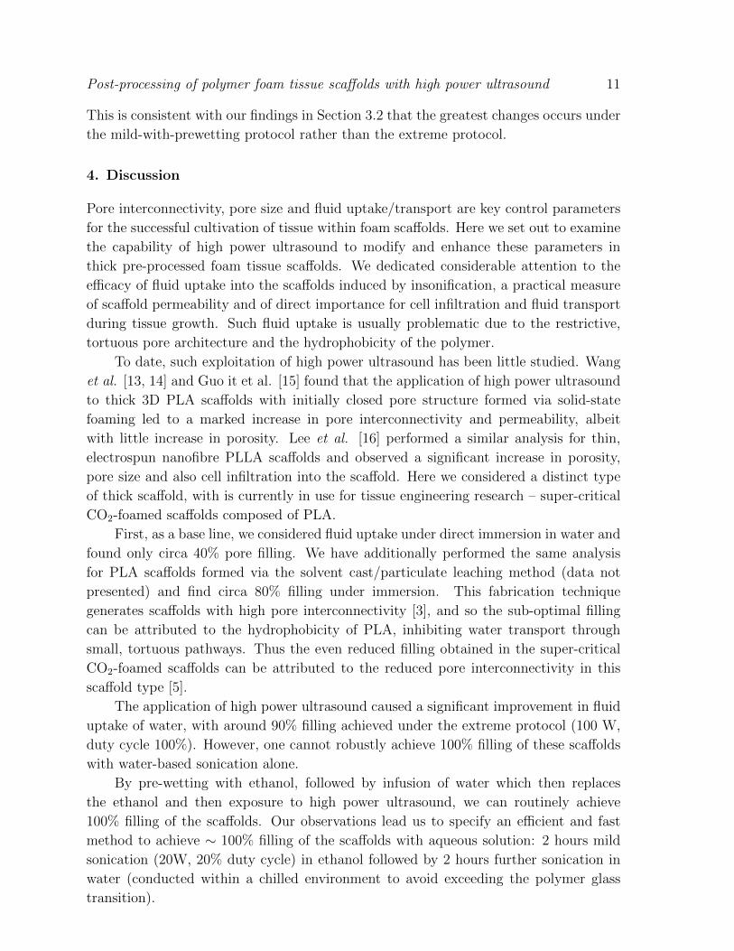
Appendix A. Thresholding in the acoustic image processing
The image processing discussed in Section 2.7 requires the setting of a threshold in
order to extract the binary image from the analog image. We analysed a single scaffold
image and determined its 2D porosity for varying values of this threshold value, with
the results shown in Figure A1. For very low thresholds, where voltage noise becomes
significant, we measure anomalously low 2D porosity. For high thresholds ( > 0.7) we
see anomalously high thresholds, caused by the effective removal of all but the strongest
reflections. In between we see a large, well-behaved range (0.05 < threshold < 0.7)
where the 2D porosity is insensitive to the threshold value and it can be assumed that
the method successfully captures the porosity value. Based on this, we employed a
threshold of 0.1 in this work.
References
[1] Ma P X and Elisseeff J H 2005 Scaffolding in Tissue Engineering (Boca Raton, FL: Taylor and
Francis)
[2] Middleton J C and Tipton A J 2000 Biomaterials 21 2335
Figure A1. 2D porosity of a typical C-scan image against the intensity threshold
value used in the binary image generation.
Post-processing of polymer foam tissue scaffolds with high power ultrasound 14
[3] Khang G, Kim M S and Lee H B 2007 A manual for biomaterials/scaffold fabrication technology
(Singapore, World Scientific Publishing)
[4] Barry J J A, Silva M M C G, Popov V K et al. 2012 Philos. Trans. R. Soc. London A 364 249
[5] White LJ, Hutter V, Tai HY, Howdle SM and Shakesheff K M 2012 Acta Biomaterialia 8 61
[6] Davies O R, Lewis A L, Whitaker M J, Tai H Y, Shakesheff K M and Howdle S M 2008 Adv. Drug
Deliver. Rev. 60 373
[7] Ginty P J, Howard D, Rose F R A J, Whitaker M J, Barry J J A, Tighe P, Mutch S R, Serhatkulu
G, Oreffo R O C, Howdle S M and Shakesheff K M 2006 P. Natl Acad. Sci. USA 1037426
[8] Mikos A G et al. 1994 Biomaterials 15 55
[9] Oh S H, Kang S G, Kim E S, Cho S H and Lee J H (2003) Biomaterials 24 4011
[10] Intranuovo F, Howard D, White L J, Johal R K, Ghaemmaghami A M, Favia P, Howdle S M,
Shakesheff K M, Alexander M R 2011 Acta Biomaterialia 7 3336
[11] Leighton T G 1997 The Acoustic Bubble (Academic Press)
[12] Leong T, Ashokkumar M and Kentish S 2011 Acoustics Australia 39 54
[13] Wang X et al 2006 Biomaterials 27 1924
[14] Wang X, Li W and Kumar V 2009 Journal of Cellular Plastics 45 353
[15] Guo G, Ma Q, Zhao B and Zhang D 2013 Ultrasonics Sonochemistry 20 137
[16] Lee J B et al. 2011 Tissue Engineering: Part A 17 2695
[17] Howdle S M et al. 2001 Chem. Commun. 109
[18] Ginty P J, Barry J J A, White L J, Howdle S M and Shakesheff K M 2008 Euro. J. Pharm.
Biopharm 68 82
[19] Kanczler J M et al 2010 Biomaterials 31 1242
[20] Kanczler J M et al 2007 Biochem. Biophys. Res. Commun. 352 135 31 1242
[21] Ahmed A R et al 2008 Eur. J. Pharm. Biopharm. 70 765-9
[22] Parker N G, Mather M L, Morgan S P and Povey M J W 2010 Biomed. Mater. 5 055004
[23] Parker N G, Mather M L, Morgan S P and Povey M J W (2011) J. Physics: Conf. Series 269
012019
[24] Lide D R 2009 CRC handbook of chemistry and physics : A ready-reference book of chemical and
physical data (Boca Raton, Fla. ; London: CRC)
[25] Parker N G et al Measur. Sci. Technol. 21 045901
[26] Mather M L et al 2008 Biomed. Mater. 3 015011
Related Documents