Fabrication and Characterization of Poly(Propylene Fumarate) Scaffolds with Controlled Pore Structures Using 3-Dimensional Printing and Injection Molding KEE-WON LEE, M.S., SHANFENG WANG, Ph.D., LICHUN LU, Ph.D., ESMAIEL JABBARI, Ph.D., BRADFORD L. CURRIER, M.D., and MICHAEL J. YASZEMSKI, M.D., Ph.D. ABSTRACT Poly(propylene fumarate) (PPF) is an injectable, biodegradable polymer that has been used for fabri- cating preformed scaffolds in tissue engineering applications because of in situ crosslinking character- istics. Aiming for understanding the effects of pore structure parameters on bone tissue ingrowth, 3-dimensional (3D) PPF scaffolds with controlled pore architecture have been produced in this study from computer-aided design (CAD) models. We have created original scaffold models with 3 pore sizes (300, 600, and 900 lm) and randomly closed 0%, 10%, 20%, or 30% of total pores from the original models in 3 planes. PPF scaffolds were fabricated by a series steps involving 3D printing of support/build constructs, dissolving build materials, injecting PPF, and dissolving support materials. To investigate the effects of controlled pore size and interconnectivity on scaffolds, we compared the porosities between the models and PPF scaffolds fabricated thereby, examined pore morphologies in surface and cross-section using scanning electron microscopy, and measured permeability using the falling head conductivity test. The thermal properties of the resulting scaffolds as well as uncrosslinked PPF were determined by differential scanning calorimetry and thermogravimetric analysis. Average pore sizes and pore shapes of PPF scaffolds with 600- and 900-lm pores were similar to those of CAD models, but they depended on directions in those with 300-lm pores. Porosity and permeability of PPF scaffolds decreased as the number of closed pores in original models increased, particularly when the pore size was 300 lm as the result of low porosity and pore occlusion. These results show that 3D printing and injection molding technique can be applied to crosslinkable polymers to fabricate 3D porous scaffolds with controlled pore structures, porosity, and permeability using their CAD models. INTRODUCTION P OLYMERIC BIOMATERIALS WITH INJECTABILITY and biode- gradability have been widely used in tissue engineer- ing. Unlike polymers used for making preformed scaffolds, injectable polymers can be crosslinked in situ through che- mical reaction or ultraviolet (UV) laser after injection to fill skeletal defects through minimally invasive surgery. 1–4 Of these polymers, poly(propylene fumarate) (PPF) is one of the promising material for tissue engineering applications, especially bone regeneration. PPF is an unsaturated linear polyester that can be crosslinked through carbon double bonds along its backbone 5,6 and degraded by simple hy- drolysis of the ester bonds into nontoxic products of pro- pylene glycol, poly(acrylic acid-co-fumaric acid), and fumaric acid. 7 Previous studies have also shown that the Tissue Engineering and Polymeric Biomaterials Laboratory, Departments of Orthopedic Surgery and Biomedical Engineering, Mayo Clinic College of Medicine, Rochester, Minnesota. TISSUE ENGINEERING Volume 12, Number 10, 2006 # Mary Ann Liebert, Inc. 2801

Welcome message from author
This document is posted to help you gain knowledge. Please leave a comment to let me know what you think about it! Share it to your friends and learn new things together.
Transcript
Fabrication and Characterization of Poly(Propylene Fumarate)
Scaffolds with Controlled Pore Structures Using 3-Dimensional
Printing and Injection Molding
KEE-WON LEE, M.S., SHANFENG WANG, Ph.D., LICHUN LU, Ph.D.,ESMAIEL JABBARI, Ph.D., BRADFORD L. CURRIER, M.D.,
and MICHAEL J. YASZEMSKI, M.D., Ph.D.
ABSTRACT
Poly(propylene fumarate) (PPF) is an injectable, biodegradable polymer that has been used for fabri-cating preformed scaffolds in tissue engineering applications because of in situ crosslinking character-istics. Aiming for understanding the effects of pore structure parameters on bone tissue ingrowth,3-dimensional (3D) PPF scaffolds with controlled pore architecture have been produced in this studyfrom computer-aided design (CAD) models. We have created original scaffold models with 3 pore sizes(300, 600, and 900 lm) and randomly closed 0%, 10%, 20%, or 30% of total pores from the originalmodels in 3 planes. PPF scaffolds were fabricated by a series steps involving 3D printing of support/buildconstructs, dissolving build materials, injecting PPF, and dissolving support materials. To investigate theeffects of controlled pore size and interconnectivity on scaffolds, we compared the porosities between themodels and PPF scaffolds fabricated thereby, examined pore morphologies in surface and cross-sectionusing scanning electron microscopy, and measured permeability using the falling head conductivity test.The thermal properties of the resulting scaffolds as well as uncrosslinked PPF were determined bydifferential scanning calorimetry and thermogravimetric analysis. Average pore sizes and pore shapes ofPPF scaffolds with 600- and 900-lm pores were similar to those of CAD models, but they depended ondirections in those with 300-lm pores. Porosity and permeability of PPF scaffolds decreased as thenumber of closed pores in original models increased, particularly when the pore size was 300lm as theresult of low porosity and pore occlusion. These results show that 3D printing and injection moldingtechnique can be applied to crosslinkable polymers to fabricate 3D porous scaffolds with controlled porestructures, porosity, and permeability using their CAD models.
INTRODUCTION
POLYMERIC BIOMATERIALS WITH INJECTABILITY and biode-
gradability have been widely used in tissue engineer-
ing. Unlike polymers used for making preformed scaffolds,
injectable polymers can be crosslinked in situ through che-
mical reaction or ultraviolet (UV) laser after injection to fill
skeletal defects through minimally invasive surgery.1–4 Of
these polymers, poly(propylene fumarate) (PPF) is one of
the promising material for tissue engineering applications,
especially bone regeneration. PPF is an unsaturated linear
polyester that can be crosslinked through carbon double
bonds along its backbone5,6 and degraded by simple hy-
drolysis of the ester bonds into nontoxic products of pro-
pylene glycol, poly(acrylic acid-co-fumaric acid), and
fumaric acid.7 Previous studies have also shown that the
Tissue Engineering and Polymeric Biomaterials Laboratory, Departments of Orthopedic Surgery and Biomedical Engineering, Mayo
Clinic College of Medicine, Rochester, Minnesota.
TISSUE ENGINEERINGVolume 12, Number 10, 2006# Mary Ann Liebert, Inc.
2801

addition of ceramic components, such as b-tricalcium phos-
phate, to PPF enhanced both mechanical strength and osteo-
conductive properties of the scaffold.8,9
To date, most PPF scaffolds have been fabricated from
crosslinking in combination with the salt-leaching techni-
que.10,11 This method can fabricate highly porous scaffolds
with various pore characteristics by controlling the content
and size of salt particles. However, there are limited appli-
cations for the scaffolds with a thin membrane, spatially
nonuniform distribution of salt particles, and incapability of
internal channel control. To overcome these limitations, a
solid freeform fabrication (SFF) technique has been con-
sidered as an alternative method. Because SFF is a compu-
terized fabrication technique that can use computer-aided
design (CAD) data directly,12,13 it has been used for man-
ufacturing other 3-dimensional (3D), polymer scaffolds with
controlled microstructures. Recently, stereolithography has
been successfully applied to make 3D PPF scaffolds for
critical-sized defects by using both UV photocrosslinking
and salt leaching,14,15 but controlling internal structures and
assessing their effects on the scaffolds have not yet been
studied. Another approach using the SFF technique is to
fabricate temporarily negative molds and cast the scaffold
by using biomaterial suspensions.16–18 Based on the original
scaffold design, negative molds were removed after they
were cast by biomaterials such as collagen,19 ceramics,20–23
polymers,24 or their composites.25 Several studies have de-
monstrated that this method was capable of fabricating
scaffolds with controlled internal structures as well as ex-
ternal shapes.19,20,22,23,25,26 Most scaffolds using a tempor-
ary mold have been fabricated by sintering ceramic or
freezing a dispersion of collagen cast into the mold, which
required a relatively high or low temperature condition.
Furthermore, 10–20% shrinkage was found in the resulting
scaffolds fabricated using those materials. Therefore, in-
jectable polymers with high crosslinkability may be suitable
for fabricating 3D scaffolds to reduce shrinkage in the final
scaffolds.
The objective of this study is to fabricate 3D porous PPF
scaffolds and demonstrate the feasibility of controlling in-
ternal pore structures of fabricating scaffolds from prede-
signed CAD models. We first designed original CAD
scaffold models with 3 pore sizes and various pore inter-
connectivities by closing different pore fractions in the
models. Based on those models, 3D negative molds were
printed and PPF scaffolds fabricated via in situ crosslinking
in the molds. To assess the effects of controlled internal
pore structures on scaffolds, the comparison between CAD
models and PPF scaffolds has been performed in terms of
porosity, pore morphology, average pore size, and perme-
ability. The comparison between porous scaffolds, PPF
itself, and a solid sample of crosslinked PPF without any
pores has also implemented by measuring their thermal
properties from differential scanning calorimetry (DSC)
and thermogravimetric analysis (TGA).
MATERIALS AND METHODS
Poly(Propylene Fumarate) synthesis
All reagents were purchased from Aldrich Chemicals
(Milwaukee, WI) and used as received, unless other-
wise indicated. PPF was synthesized as described pre-
viously.27,28 Briefly, diethyl fumarate, excess amount of
1,2-propylene glycol were polymerized together with hy-
droquinone (crosslinking inhibitor) and zinc chloride (cat-
alyst) first at 1008C for 1 h and then 1508C for 7 h to obtain
fumaric diester intermediate. The intermediate was trans-
esterified to form PPF under vacuum at 1508C for another
7 h. Gel permeation chromatography (GPC) was used to
determine the molecular weights and polydispersity of PPF.
The GPC was carried out with a Waters 717 Plus Auto-
sampler GPC system (Waters, Milford, MA) connected to a
model 515 HPLC pump and model 2410 refractive index
detector. Monodisperse polystyrene (PS) standards (Poly-
sciences, Warrington, PA) with number average molecular
weights (Mn) of 474, 6,690, 18,600, and 38,000 g/mol were
used to construct the calibration curve. The Mn and weight
average molecular weights (Mw) of the synthesized PPF
were 3,460 and 7,910 g/mol, respectively.
Scaffold modeling in computer-aided design
We used 3D CAD software, Solidworks (SolidWorks
Corp., Concord, MA), to create original scaffold models.
Unit cell geometry is an orthogonal cubic lattice structure
with square pores, which have 3 different sizes (300, 600,
and 900 mm) and a 300-mm strut thickness. Using the Boo-
lean operation, each pore of original scaffold models was
fully interconnected to the adjacent pores spaced by a 600-
mm strut thickness. Dimensions of 3 original scaffold models
are 1.08�1.08�1.08 cm (for 300 and 600 mm) and 1.05�1.05�1.05 cm (for 900 mm). To control pore intercon-
nectivity, we first calculated total pores in original scaffold
models. The total number of closed pores for each scaffold
was determined from calculating 10%, 20%, and 30% of the
total pores in 3 original scaffold models. Then we defined 2
outer layers and several intermediate layers in original
scaffold models from 3 planes to allocate the number of
closed pores to each scaffold. Based on these calculations,
the total number of closed pores per layer was determined by
dividing 10%, 20%, and 30% closed pores into total number
of layers, which was allocated randomly within each layer
and closed by extruding feature in 3 planes: plane 1 (x–y
plane), plane 2 (y–z plane), and plane 3 (x–z plane).
Poly(Propylene Fumarate) scaffold fabrication
All CAD models were converted to stereolithography
(STL) files, and then 2-dimensional (2D) sliced data (PTM)
files with a 0.076mm of thickness using the ModelWorks
software (Solidscape Corp., Merrimack, NH). The 3D
2802 LEE ET AL.
phase-change ink jet printer, PatternMaster, was used to
create 3D scaffolds for printing PTM files layer by layer
with a build material (PS) and a support material (wax).
After printing, PS was dissolved by immersing printed
scaffolds into acetone for 30min to obtain wax molds.
Subsequently, the wax mold was put into a Teflon holder,
and PPF polymerizing mixture was injected under
100mmHg vacuum. PPF was crosslinked by a free radical
polymerization using benzoyl peroxide (BPO), dimethyl
toluidine (DMT), 1-vinyl-2-pyrrolidinone (NVP), and me-
thylene chloride as free radical initiator, accelerator,
crosslinker, and diluent, respectively. A typical procedure
for preparation of the PPF polymerizing mixture was as
follows. Two and a half grams of PPF and 1.0 g of NVP
were mixed in a glass vial at 378C. One hundred microliters
of initiator solution (50mg of BPO in 250 mL of NVP) and
40 mL of accelerator solution (20 mL of DMT in 980 mL of
methylene chloride) were added and mixed. To facilitate
crosslinking, scaffolds were put into the oven at 408C for
1 h. After crosslinking was completed, the scaffolds were
detached from the Teflon holder and wax was dissolved in a
cleaner solution (BIOACT VS-O, Petroferm Inc., Fernan-
dina Beach, FL) at 40–608C for 1 h. Finally, the scaffolds
were dried completely at ambient temperature. All the
scaffolds were fabricated at the same time using the same
batch of PPF.
Scaffold characterization
Porosity. In CAD models, porosity was determined from
½1� Vsolid=Vtotal� · 100ð%Þ
Where Vsolid is the solid volume and Vtotal is the total volume
of scaffold. To determine porosity of PPF scaffolds, mass
and all dimensions (length, width, and height) of 5 scaf-
folds were measured. Porosity of PPF scaffolds was calcu-
lated by
½1� ðmscaffold=vscaffoldÞ=qPPF � · 100ð%Þ
where vscaffold is the total volume, mscaffold is the dry mass of
PPF scaffold, and rPPF is the density of PPF (~1.3 g/cm3).28
SEM analysis. Cold-field emission scanning electron
microscopy (S-4700, Hitachi Instruments Inc., Tokyo,
Japan) was used to examine the pore morphology of PPF
scaffolds in the surface and cross-section. For cross-
sectional images, scaffolds were cryosectioned in liquid
nitrogen through their middle parts parallel to planes 1 and 2.
All the scaffolds were viewed at 3 kV accelerating voltage
and 9500 nA emission current. Average pore sizes were
calculated from SEM images by using the biomedical image
analysis software, Analyze (BIR Mayo Clinic, Rochester,
MN).
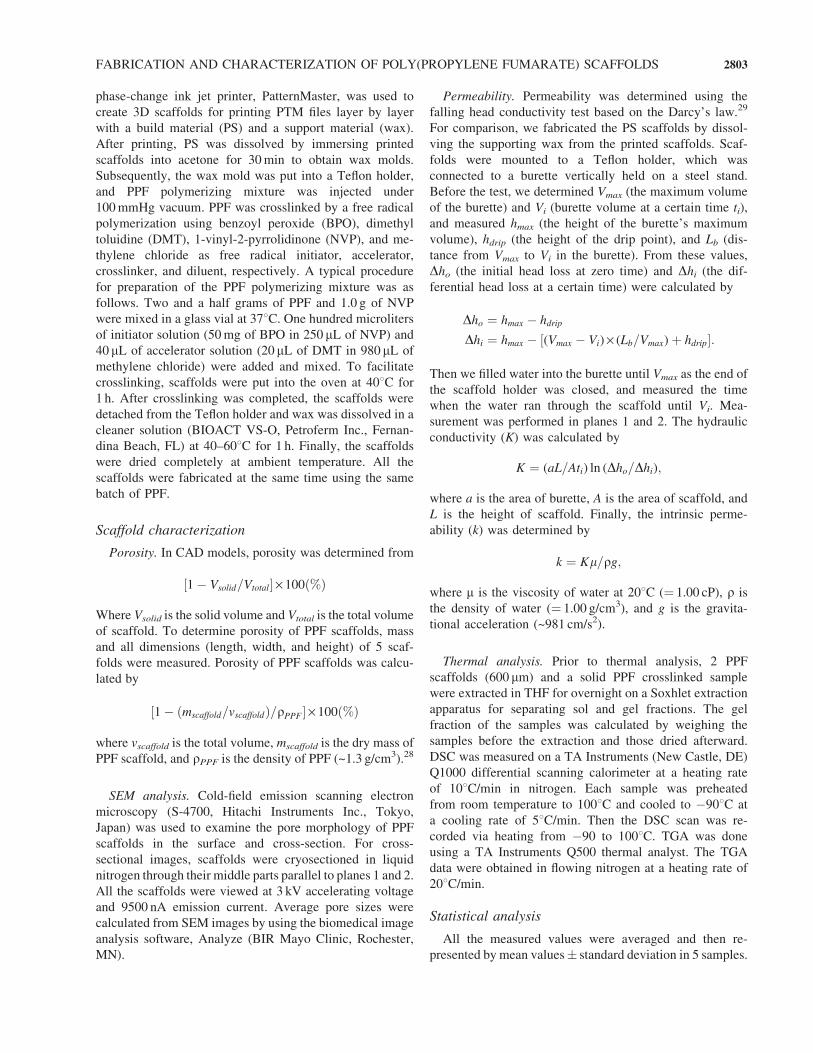
Permeability. Permeability was determined using the
falling head conductivity test based on the Darcy’s law.29
For comparison, we fabricated the PS scaffolds by dissol-
ving the supporting wax from the printed scaffolds. Scaf-
folds were mounted to a Teflon holder, which was
connected to a burette vertically held on a steel stand.
Before the test, we determined Vmax (the maximum volume
of the burette) and Vi (burette volume at a certain time ti),
and measured hmax (the height of the burette’s maximum
volume), hdrip (the height of the drip point), and Lb (dis-
tance from Vmax to Vi in the burette). From these values,
Dho (the initial head loss at zero time) and Dhi (the dif-
ferential head loss at a certain time) were calculated by
Dho ¼ hmax � hdrip
Dhi ¼ hmax � ½(Vmax � Vi) · (Lb=Vmax)þ hdrip�:
Then we filled water into the burette until Vmax as the end of
the scaffold holder was closed, and measured the time
when the water ran through the scaffold until Vi. Mea-
surement was performed in planes 1 and 2. The hydraulic
conductivity (K) was calculated by
K ¼ (aL=Ati) ln (Dho=Dhi);
where a is the area of burette, A is the area of scaffold, and
L is the height of scaffold. Finally, the intrinsic perme-
ability (k) was determined by
k ¼ Kl=qg;
where m is the viscosity of water at 208C (¼ 1.00 cP), r is
the density of water (¼ 1.00 g/cm3), and g is the gravita-
tional acceleration (~981 cm/s2).
Thermal analysis. Prior to thermal analysis, 2 PPF
scaffolds (600 mm) and a solid PPF crosslinked sample
were extracted in THF for overnight on a Soxhlet extraction
apparatus for separating sol and gel fractions. The gel
fraction of the samples was calculated by weighing the
samples before the extraction and those dried afterward.
DSC was measured on a TA Instruments (New Castle, DE)
Q1000 differential scanning calorimeter at a heating rate
of 108C/min in nitrogen. Each sample was preheated
from room temperature to 1008C and cooled to �908C at
a cooling rate of 58C/min. Then the DSC scan was re-
corded via heating from �90 to 1008C. TGA was done
using a TA Instruments Q500 thermal analyst. The TGA
data were obtained in flowing nitrogen at a heating rate of
208C/min.
Statistical analysis
All the measured values were averaged and then re-
presented by mean values� standard deviation in 5 samples.
FABRICATION AND CHARACTERIZATION OF POLY(PROPYLENE FUMARATE) SCAFFOLDS 2803

Student’s t-test was performed to assess statistically sig-
nificances ( p< .05) of porosity and permeability between
CAD models and PPF scaffolds.
RESULTS
Computer-aided design model
We generated 3D scaffold models with different pore
sizes and percentages of closed pores in CAD (Fig. 1). Pore
connection control was implemented by calculating total
number of pores and different percentage closed pores in
original scaffold models (Table 1) and closing them ran-
domly in 3 planes. At a pore size of 900 mm, for example,
scaffolds had 8 layers: 2 outer layers (top and bottom) and 6
intermediate layers. Each 2D sliced image represented ran-
domly closed pores within 8 layers of scaffold in the plane
1. All dimensions (length�width�height) of PPF scaffolds
no closed pores at 300-, 600-, and 900-mm pore sizes
were (1.06� 0.08)�(1.07� 0.05)�(1.04� 0.09) cm, (1.07�0.03)�(1.07� 0.03)�(1.04� 0.01) cm, and (1.03� 0.01)�(1.03� 0.02)�(1.02� 0.04) cm, respectively. Comparing
these data with those of CADmodels, maximum percentage
of decrease in each dimension of PPF scaffolds was only
1.9% for length and width, and 3.7% for height; however,
there was no statistically significant difference between PPF
scaffolds and CAD models.
Poly(Propylene Fumarate) scaffold fabrication
The fabrication process of PPF scaffolds consisted of 4
steps: (1) printing on a 3D phase-change ink jet printer, (2)
dissolving the build material (PS), (3) injecting PPF, and
(4) dissolving the support material (wax) (Fig 2). Printed
scaffolds were composed of the green build material sur-
rounded with the orange support material. Dissolving the
build material was achieved by putting printed scaffolds
into acetone. After dissolving build materials, negative wax
molds for injecting PPF were obtained. Under the vacuum,
PPF was infiltrated into pores of negative wax molds. Fi-
nally, PPF scaffolds were obtained by dissolving wax in a
cleaner solution and drying them completely at ambient
temperature. Like dissolving the build materials, comple-
tion of dissolving wax was indicated from the color change
of the cleaner solution. This step consumes more time than
the dissolving the build material, although it can be ex-
pedited at a higher temperature (758C).
Porosity
Based on pore connection control in CAD models, as the
number of closed pores increased, porosity of both CAD
FIG. 1. Schematics of the original scaffold model and the pore interconnectivity control in CAD. (A) The original scaffold model with
900 mm pores in 3 planes. (B) 2D sliced images (from top to bottom layer in plane 1) of the scaffold model with 10%, 20%, and 30%
closed pores of total number of pores. (C) Final scaffold models.
TABLE 1. CLOSED PORE CALCULATION OF THREE ORIGINAL
SCAFFOLDS IN COMPUTER-AIDED DESIGN
Pore size (mm) 300 600 900
Number of pores in one row 12 9 7
Total number of pores in original models 5616 2430 1176
Total number of 10% closed pores 562 243 118
Total number of 20% closed pores 1123 486 235
Total number of 30% closed pores 1685 729 353
2804 LEE ET AL.
models and PPF scaffolds decreased (Fig. 3). At a pore size
of 300 mm, porosity of PPF scaffolds was significantly
lower than that of CAD models in 4 different percentages
of closed pores ( p< .05) and decreased abruptly to 29.5%
in changing from 0 to 10% closed pore control. After this
change, porosity decreased to 15.7% and 17.0% in 2 other
closed pore controls. The difference of porosity between
CAD models and PPF scaffolds increased as the number of
closed pores from the original scaffold model increased
(Table 2). However, there were no significant differences of
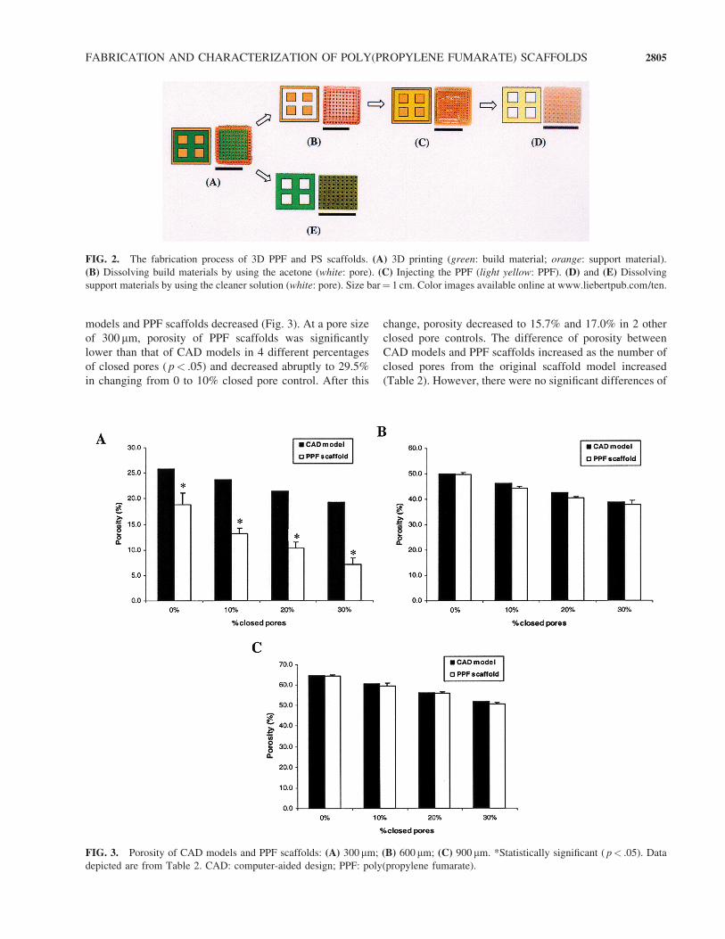
FIG. 2. The fabrication process of 3D PPF and PS scaffolds. (A) 3D printing (green: build material; orange: support material).
(B) Dissolving build materials by using the acetone (white: pore). (C) Injecting the PPF (light yellow: PPF). (D) and (E) Dissolving
support materials by using the cleaner solution (white: pore). Size bar¼ 1 cm. Color images available online at www.liebertpub.com/ten.
FIG. 3. Porosity of CAD models and PPF scaffolds: (A) 300 mm; (B) 600 mm; (C) 900 mm. *Statistically significant ( p< .05). Data
depicted are from Table 2. CAD: computer-aided design; PPF: poly(propylene fumarate).
FABRICATION AND CHARACTERIZATION OF POLY(PROPYLENE FUMARATE) SCAFFOLDS 2805
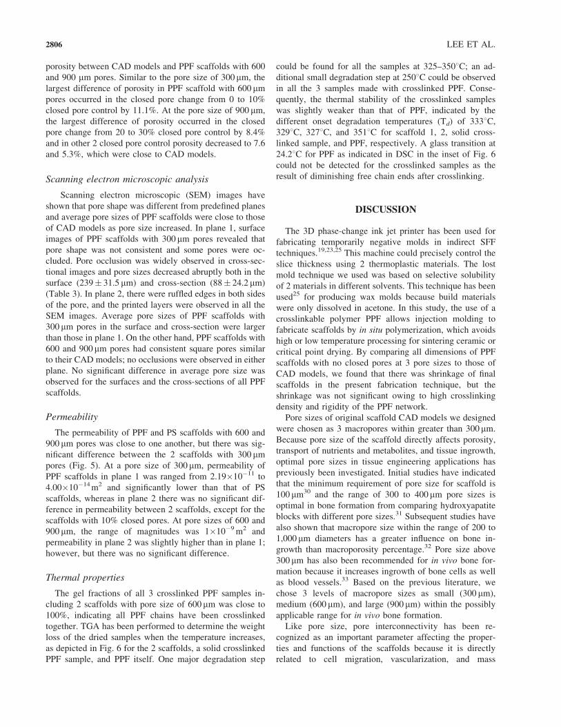
porosity between CAD models and PPF scaffolds with 600
and 900 mm pores. Similar to the pore size of 300 mm, the
largest difference of porosity in PPF scaffold with 600 mmpores occurred in the closed pore change from 0 to 10%
closed pore control by 11.1%. At the pore size of 900 mm,
the largest difference of porosity occurred in the closed
pore change from 20 to 30% closed pore control by 8.4%
and in other 2 closed pore control porosity decreased to 7.6
and 5.3%, which were close to CAD models.
Scanning electron microscopic analysis
Scanning electron microscopic (SEM) images have
shown that pore shape was different from predefined planes
and average pore sizes of PPF scaffolds were close to those
of CAD models as pore size increased. In plane 1, surface
images of PPF scaffolds with 300 mm pores revealed that
pore shape was not consistent and some pores were oc-
cluded. Pore occlusion was widely observed in cross-sec-
tional images and pore sizes decreased abruptly both in the
surface (239� 31.5 mm) and cross-section (88� 24.2 mm)
(Table 3). In plane 2, there were ruffled edges in both sides
of the pore, and the printed layers were observed in all the
SEM images. Average pore sizes of PPF scaffolds with
300 mm pores in the surface and cross-section were larger
than those in plane 1. On the other hand, PPF scaffolds with
600 and 900 mm pores had consistent square pores similar
to their CAD models; no occlusions were observed in either
plane. No significant difference in average pore size was
observed for the surfaces and the cross-sections of all PPF
scaffolds.
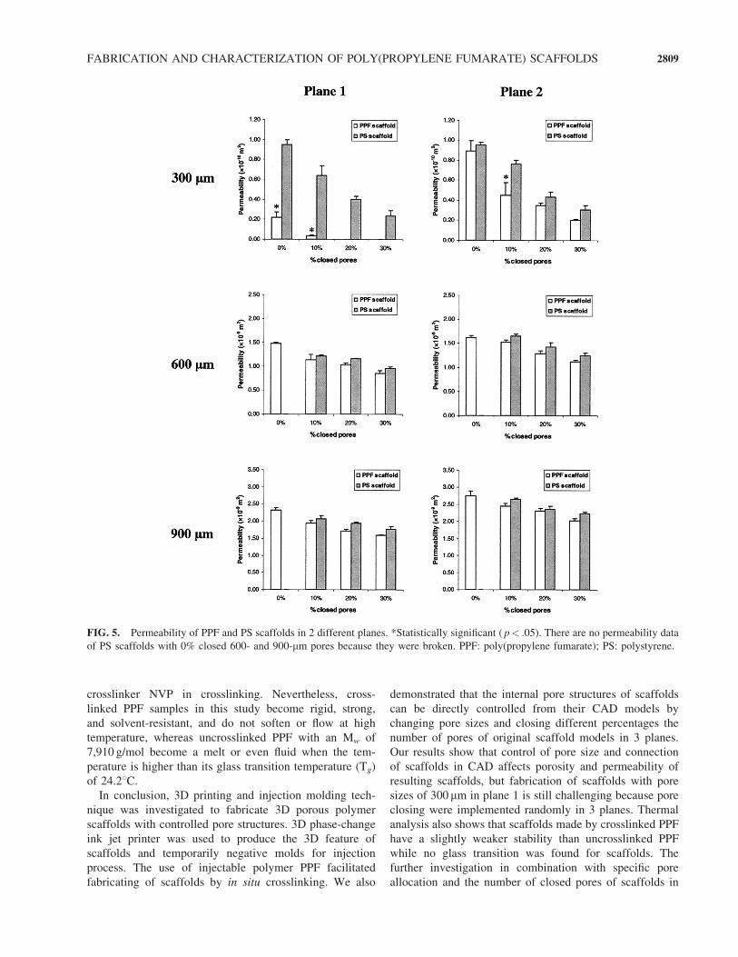
Permeability
The permeability of PPF and PS scaffolds with 600 and
900 mm pores was close to one another, but there was sig-
nificant difference between the 2 scaffolds with 300 mmpores (Fig. 5). At a pore size of 300 mm, permeability of
PPF scaffolds in plane 1 was ranged from 2.19�10�11 to
4.00�10�14m2 and significantly lower than that of PS
scaffolds, whereas in plane 2 there was no significant dif-
ference in permeability between 2 scaffolds, except for the
scaffolds with 10% closed pores. At pore sizes of 600 and
900 mm, the range of magnitudes was 1�10�9m2 and
permeability in plane 2 was slightly higher than in plane 1;
however, but there was no significant difference.
Thermal properties
The gel fractions of all 3 crosslinked PPF samples in-
cluding 2 scaffolds with pore size of 600 mm was close to
100%, indicating all PPF chains have been crosslinked
together. TGA has been performed to determine the weight
loss of the dried samples when the temperature increases,
as depicted in Fig. 6 for the 2 scaffolds, a solid crosslinked
PPF sample, and PPF itself. One major degradation step
could be found for all the samples at 325–3508C; an ad-
ditional small degradation step at 2508C could be observed
in all the 3 samples made with crosslinked PPF. Conse-
quently, the thermal stability of the crosslinked samples
was slightly weaker than that of PPF, indicated by the
different onset degradation temperatures (Td) of 3338C,3298C, 3278C, and 3518C for scaffold 1, 2, solid cross-
linked sample, and PPF, respectively. A glass transition at
24.28C for PPF as indicated in DSC in the inset of Fig. 6
could not be detected for the crosslinked samples as the
result of diminishing free chain ends after crosslinking.
DISCUSSION
The 3D phase-change ink jet printer has been used for
fabricating temporarily negative molds in indirect SFF
techniques.19,23,25 This machine could precisely control the
slice thickness using 2 thermoplastic materials. The lost
mold technique we used was based on selective solubility
of 2 materials in different solvents. This technique has been
used25 for producing wax molds because build materials
were only dissolved in acetone. In this study, the use of a
crosslinkable polymer PPF allows injection molding to
fabricate scaffolds by in situ polymerization, which avoids
high or low temperature processing for sintering ceramic or
critical point drying. By comparing all dimensions of PPF
scaffolds with no closed pores at 3 pore sizes to those of
CAD models, we found that there was shrinkage of final
scaffolds in the present fabrication technique, but the
shrinkage was not significant owing to high crosslinking
density and rigidity of the PPF network.
Pore sizes of original scaffold CAD models we designed
were chosen as 3 macropores within greater than 300 mm.
Because pore size of the scaffold directly affects porosity,
transport of nutrients and metabolites, and tissue ingrowth,
optimal pore sizes in tissue engineering applications has
previously been investigated. Initial studies have indicated
that the minimum requirement of pore size for scaffold is
100 mm30 and the range of 300 to 400 mm pore sizes is
optimal in bone formation from comparing hydroxyapatite
blocks with different pore sizes.31 Subsequent studies have
also shown that macropore size within the range of 200 to
1,000 mm diameters has a greater influence on bone in-
growth than macroporosity percentage.32 Pore size above
300 mm has also been recommended for in vivo bone for-
mation because it increases ingrowth of bone cells as well
as blood vessels.33 Based on the previous literature, we
chose 3 levels of macropore sizes as small (300 mm),
medium (600 mm), and large (900 mm) within the possibly
applicable range for in vivo bone formation.
Like pore size, pore interconnectivity has been re-
cognized as an important parameter affecting the proper-
ties and functions of the scaffolds because it is directly
related to cell migration, vascularization, and mass
2806 LEE ET AL.
transport3,12,20,25; however, little work has been presented
on fabricating scaffolds with controlled interconnectivity or
subsequently assessing its effects. To quantitatively asses-
sing the effects of pore interconnectivity on scaffold
property, we designed CAD models with varied degrees of
interconnectivity. Because increasing the number of closed
pores in predefined layers of the CAD model decreases
pore interconnectivity, we were able to control porosity
and pore interconnectivity of scaffolds by varying the per-
centage of closed pores from total pores of CAD models.
The scaffolds investigated in this study had either fully
interconnected network with no closed pores or semi-
interconnected network with 10%, 20%, or 30% closed
pores, which was similar to the typical scaffolds fabricated
by various conventional techniques such as salt-leaching
technique, which typically results in randomized pore
connections inside the scaffolds, even at relatively high
porosity.
As shown in Table 2, porosity of CAD models decreased
constantly to 8.5% (for 300 mm), 7.4% (600 mm), and 6.6%
(900 mm) whenever the number of closed pores from ori-
ginal CAD models increased to 10%. These decreased
porosities were observed in PPF scaffolds, following de-
creased permeability of PPF scaffolds. But, porosity de-
crease of PPF scaffolds with 300 mm pores did not match
that of CAD models, owing to some possible reasons. First,
original CAD model with 300 mm pores had low porosity
(25.9%). Porosity of CAD models depended mainly on a
pore size and a strut thickness, which were determined as
300 mm in this study, considering a minimum printable
feature size (250 mm) of the machine. This strut thickness
was 300 mm between outer ends of each face and pores, but
it was 600 mm between 2 adjacent pores, which causes a
low porosity in original CAD models with 300 mm pores.
Second, random pore closing led to reduced pore inter-
connectivity within the scaffolds. Three original CAD
models had only passing pores to connect 2 outer surfaces
in each plane. However, as the number of closed pores
increased, random closing in 3 planes increased nonpassing
pores, which connect only 1 outer surface or isolated pores
and have no connections to the adjacent pores or the outer
surface in each plane. Although the apparent porosity we
calculated could not distinguish passing pores from non-
passing or isolated pores, the effect of random pore closing
was observed markedly in PPF scaffolds with 300 mmpores. At this pore size, the largest difference of porosity
between PPF scaffolds and CAD models was observed
when the closed pore was changed from 0 to 10%, and pore
occlusions occurred in both the surface and the cross-sec-
tion of PPF scaffolds, even without closed pores in plane 1
(Fig. 4). These results suggest that build and support ma-
terials might not be removed completely during the dis-
solving process.
The direction-dependent pore shape of fabricated scaf-
folds using the 3D phase-change ink jet printer has also
been investigated by Wilson et al.23 Because 3D printing
is a layer-based fabrication technique that can fabricate a
3D feature by printing its 2D slices with build and sup-
port materials and accumulating them subsequently in z-
direction, pores of PPF scaffolds in plane 1 were generated
directly by printing their 2D slices, but those in other planes
were generated by an accumulating process. Basically,
these 2 pore-generating processes have led to different pore
shapes of PPF scaffolds in planes 1 and 2 (as shown in
Fig. 4). From all the SEM images in the surface and cross-
section, ruffled edges and printed layers in both sides of the
pore were observed in plane 2. Also, while dissolving build
materials, pores in plane 1 were only exposed and directly
faced with the acetone. In the case of PPF scaffold with
300 mm pores, acetone did not easily penetrate into deeper
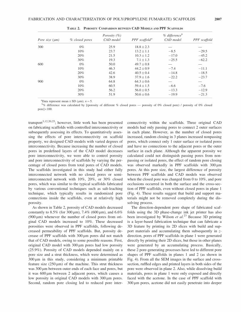
TABLE 2. POROSITY COMPARISON BETWEEN CAD MODELS AND PPF SCAFFOLDS
Porosity (%) % differenceb
Pore size (mm) % closed pores CAD model PPF scaffolda CAD model PPF scaffold
300 0% 25.9 18.8� 2.3 — —
10% 23.7 13.2� 1.1 �8.5 �29.5
20% 21.5 10.3� 1.2 �17.0 �45.2
30% 19.3 7.1� 1.3 �25.5 �62.2
600 0% 50.0 49.7� 0.8 — —
10% 46.3 44.2� 0.9 �7.4 �11.1
20% 42.6 40.5� 0.4 �14.8 �18.5
30% 38.9 37.9� 1.6 �22.2 �23.7
900 0% 64.8 64.3� 0.6 — —
10% 60.5 59.4� 1.5 �6.6 �7.6
20% 56.2 56.0� 0.5 �13.3 �12.9
30% 51.9 50.6� 0.6 �19.9 �21.3
aData represent mean�SD (mm); n¼ 5.b% difference was calculated by [(porosity of different % closed pores — porosity of 0% closed pore) / porosity of 0% closed
pore]�100.
FABRICATION AND CHARACTERIZATION OF POLY(PROPYLENE FUMARATE) SCAFFOLDS 2807

areas of the scaffold, which might influence changes of
pore shape as round rather than square and reduced average
pore sizes (as shown in Table 3). However, because pores
in other planes were shielded by support materials and
Teflon holders during PPF injection, pore shape was close
to square and there were no significant differences of
average pore sizes between PPF scaffolds and CAD models
in the surface as well as cross-section, irrespective of pore
sizes. Compared to the results from previous studies,
average pore sizes of PPF scaffolds with 600 mm pores in
this study were similar to the original pore size of CAD
models, but those with 300 mm pores varied as different
planes. Sachlos et al.19 fabricated collagen scaffolds with
spheres and rods designed at different dimensions. The
dimensions of the designed scaffolds with sphere of 600 mmand interconnection of 300 mm were approximately 590–
610 and 340 mm, respectively. Wilson et al.23 fabricated
hydroxyapatite scaffolds with square cross-sectional chan-
nels of 400 mm. The dimensions of channels were ap-
proximately 280 or 286 mm in the x–y plane, 376 or 394 mmin the y–z plane, and 339 or 352 mm in the x–z plane.
In addition to porosity and average pore size, permeability
has been investigated in previous studies for describing
structure of scaffolds and modeling of the porous materi-
als.34–37 Because intrinsic permeability is a property of the
porous scaffolds only, in contrast to the hydraulic con-
ductivity, which is a property of both the porous scaffolds
and the water content of the scaffold, it could be used an
another parameter for characterizing the pore interconnec-
tion of PPF scaffolds in this study. Significantly low mag-
nitude PPF scaffolds and large difference between PS and
PPF scaffolds at a pore size of 300 mm in plane 1 as com-
pared to those in plane 2 (Fig. 5) have also mirrored effects
of low porosity and random pore closing. Considered as a
strong correlation between porosity and permeability when
the pores of scaffolds are highly interconnected,38 the per-
meability we measured shows indirectly that the pores of
PPF scaffolds are well interconnected.
Thermal analysis of the 2 porous PPF scaffolds (in Fig. 6)
shows they are essentially the same as a solid crosslinked
PPF sample and all are slightly weaker than uncross-
linked PPF in thermal stability because of the addition of
FIG. 4. SEM images of PPF scaffolds with 0% closed pores in 2 different planes. Size bar¼ 400 mm.
TABLE 3. AVERAGE PORE SIZES OF PPF SCAFFOLDS WITH 0% CLOSED PORES IN TWO DIFFERENT PLANES
Pore size in CAD models (mm) 300 600 900
Plane 1 Surface 239� 31.5 617� 16.7 908� 18.8
(x–y plane) Cross-section 88� 24.2 590� 21.3 912� 19.8
Plane 2 Surface 271� 20.6 620� 23.4 917� 13.8
(y–z plane) Cross-section 277� 24.0 598� 21.2 884� 54.7
Data represent mean�SD (mm); n¼ 5.
2808 LEE ET AL.
crosslinker NVP in crosslinking. Nevertheless, cross-
linked PPF samples in this study become rigid, strong,
and solvent-resistant, and do not soften or flow at high
temperature, whereas uncrosslinked PPF with an Mw of
7,910 g/mol become a melt or even fluid when the tem-
perature is higher than its glass transition temperature (Tg)
of 24.28C.In conclusion, 3D printing and injection molding tech-
nique was investigated to fabricate 3D porous polymer
scaffolds with controlled pore structures. 3D phase-change
ink jet printer was used to produce the 3D feature of
scaffolds and temporarily negative molds for injection
process. The use of injectable polymer PPF facilitated
fabricating of scaffolds by in situ crosslinking. We also
demonstrated that the internal pore structures of scaffolds
can be directly controlled from their CAD models by
changing pore sizes and closing different percentages the
number of pores of original scaffold models in 3 planes.
Our results show that control of pore size and connection
of scaffolds in CAD affects porosity and permeability of
resulting scaffolds, but fabrication of scaffolds with pore
sizes of 300 mm in plane 1 is still challenging because pore
closing were implemented randomly in 3 planes. Thermal
analysis also shows that scaffolds made by crosslinked PPF
have a slightly weaker stability than uncrosslinked PPF
while no glass transition was found for scaffolds. The
further investigation in combination with specific pore
allocation and the number of closed pores of scaffolds in
FIG. 5. Permeability of PPF and PS scaffolds in 2 different planes. *Statistically significant ( p< .05). There are no permeability data
of PS scaffolds with 0% closed 600- and 900-mm pores because they were broken. PPF: poly(propylene fumarate); PS: polystyrene.
FABRICATION AND CHARACTERIZATION OF POLY(PROPYLENE FUMARATE) SCAFFOLDS 2809

their CAD models will be expected to control internal pore
structures, porosity, and permeability more accurately.
ACKNOWLEDGMENTS
This study was completed through funding provided by
the Mayo Foundation and the National Institutes of Health
(R01AR45871 and R01EB003060). The authors acknowl-
edge James A. Gruetzmacher for technical assistance,
Fredrick M. Schultz for manufacturing Teflon molds, and
Jon E. Charlesworth for scanning samples with SEM.
REFERENCES
1. Temenoff, J.S., and Mikos, A.G. Injectable biodegradable
materials for orthopedic tissue engineering. Biomaterials 21,
2405, 2000.
2. Agrawal, C.M., and Ray, R.B. Biodegradable polymeric
scaffolds for musculoskeletal tissue engineering. J. Biomed.
Mater. Res. 55, 141, 2001.
3. Lu, L., Zhu, X., Valenzuela, R.G., Currier, B.L., and Yas-
zemski, M.J. Biodegradable polymer scaffolds for cartilage
tissue engineering. Clin. Orthop. 391, S251, 2001.
4. Peter, S.J., Yaszemski, M.J., Suggs, L.J., Payne, R.G., Langer,
R.S., Hayes, W.C., Unroe, M.R., Alemany, L.B., Engel, P.S.,
and Mikos, A.G. Characterization of partially saturated
ploy(propylene fumarate) for orthopedic application. J. Bio-
mater. Sci. Polym. Ed. 8, 11, 893, 1997.
5. Peter, S.J., Miller, M.J., Yasko, A.W., Yaszemski, M.J., and
Mikos, A.G. Polymer concepts in tissue engineering. J.
Biomed. Mater. Res. 43, 422, 1998.
6. Domb, A.J., Manor, N., and Elmalak, O. Biodegradable bond
cement compositions based on acrylate and epoxide termi-
nated poly(propylene fumarate) oligomers and calcium salt
compositions. Biomaterials 17, 411, 1996.
7. He, S., Timmer, M.D., Yaszemski, M.J., Yasko, A.W., Engel,
P.S., and Mikos, A.G. Synthesis of biodegradable poly
(propylene fumarate) networks with poly(propylene fumarate)-
diacylate macromers as crosslinking agents and characterization
of their degradation products. Polymer, 42, 1251, 2001.
8. Peter, S.J., Kim, P., Yasko, A.W., Yaszemski, M.J., and Mikos,
A.G. Crosslinking characteristics of an injectable poly (propy-
lene fumarate)/b-tricalcium phosphate paste and mechanical
properties of the crosslinked composite for use as a biodegrad-
able bone cement. J. Biomed. Mater. Res. 44, 314, 1999.
9. Peter, S.J., Lu, L., Kim, D.J., and Mikos, A.G. Marrow
stromal osteoblast function on a poly(propylene fumarate)/
b-tricalcium phosphate biodegradable orthopedic composite.
Biomaterials 21, 1207, 2000.
10. Yaszemski, M.J., Payne, R.G., Hayes, W.C., Langer, R.S.,
Aufdemorte, T.B., and Mikos, AG. The ingrowth of new bone
tissue and initial mechanical properties of a degrading poly-
meric composite scaffold. Tissue Eng. 1, 41, 1995.
11. Fisher, J.P., Holland, T.A., Dean, D., Engel, P.S., Mikos, A.G.
Synthesis and properties of photocrosslinked poly(propylene
fumarate) scaffolds. J. Biomater. Sci. Polym. Ed. 12, 6, 673,
2001
12. Leong, K.F., Cheah, C.M., and Chua, C.K. Solid freeform
fabrication of three-dimensional scaffolds for engineering
replacement tissues and organs. Biomaterials 24, 2363, 2003.
13. Yang, S.F., Leong, K.F., Du, Z.H., and Chua, C.K. The design
of scaffolds for use in tissue engineering. Part II. Rapid
prototyping techniques. Tissue Eng. 8, 1, 2002.
14. Cooke, M.N., Fisher, J.P., Dean, D., Rimnac, C., and Mikos,
A.G. Use of stereolithography to manufacture critical-sized
3D biodegradable scaffolds for bone ingrowth. J. Biomed.
Mater. Res. Part B: Appl. Biomater. 64B, 65, 2002.
15. Fisher, J.P., Vehof, J.W.M., Dean, D., van der Waerden,
J.P.C.M., Holland, T.A., Mikos, A.G., and Jansen, J.A. Soft
and hard tissue response to photocrosslinked poly(propylene
fumarate) scaffolds in a rabbit model. J. Biomed. Mater. Res.
59, 547, 2002.
16. Sun, W., and Lai, P. Recent development on computer aided
tissue engineering—A review. Comput. Methods Programs
Biomed. 67, 85, 2002.
17. Sachlos, E., and Czernuszka, J.T. Making tissue engineering
scaffolds work. Review on the application of solid freeform
fabrication technology to the production of tissue engineering
scaffolds. European Cells Mater. 5, 29, 2003.
18. Hutmacher, D.W., Sittinger, M., and Risbud, M.V. Scaffold-
based tissue engineering: Rationale for computer-aided design
and solid free-form fabrication systems. Trends Biotech. 22,
354, 2004.
19. Sachlos, E., Reis, N., Ainsley, C., Derby, B., and Czernuszka,
J.T. Novel collagen scaffolds with predefined internal mor-
phology made by solid freeform fabrication. Biomaterials 24,
1487, 2003.
20. Chu, T.M.G., Halloran, J.W., Hollister, S.J., and Feinberg,
S.E. Hydroxyapatite implants with designed internal archi-
tecture. J. Mater. Sci. Mater. Med. 12, 471, 2001.
21. Bose, S., Darsell, J., Hosick, H., Yany, L., Sarrkar, D.K., and
Bandyopahhyay, A. Processing and characterization of alu-
mina scaffolds. J. Mater. Sci. Mater. Med. 13, 23, 2002.
FIG. 6. TGA thermograms and DSC curves (inset) of the 2
scaffolds with pore size of 600mm, a solid crosslinked PPF
sample, and PPF itself. PPF: poly(propylene fumarate)
2810 LEE ET AL.
22. Hollister, S.J., Maddox, R.D., and Taboas, J.M. Optimal design
and fabrication of scaffolds to mimic tissue properties and
satisfy biological constraints. Biomaterials 23, 4095, 2002.
23. Wilson, C.E., de Bruijn, J.D., van Blitterswijk, C.A., Verbout,
A.J., and Dhert, W.J.A. Design and fabrication of standar-
dized hydroxyapatite scaffolds with a defined macro-
architecture by rapid prototyping for bone tissue engineering
research. J. Biomed. Mater. Res. 68A, 123, 2004.
24. Sodian, R., Loebe, M., Hein, A., Martin, D.P., Hoerstrup,
S.P., Potapov, E.V., Hausmann, H., Lueth, T., and Hetzer, R.
Application for stereolithography for scaffold fabrication for
tissue engineered heart valves. ASAIO 48, 12, 2002.
25. Taboas, J.M., Maddox, R.D., Krebsbach, P.H., and Hollister,
S.J. Indirect solid freefrom fabrication of local and global
porous, biomimetic and composite 3D polymer-ceramic
scaffolds. Biomaterials 24, 181, 2003.
26. Chu, T.M.G., Orton, D.G., Hollister, S.J., Feinberg, S.E., and
Halloran, J.W. Mechanical and in vivo performance of hy-
droxyapatite implants with controlled architecture. Bioma-
terials 23, 1283, 2002.
27. Kharas, G.B., Kamenetsky, M., Simantirakis, J., Beinlich,
K.C., Rizzo, A.M.T., Caywood, G.A., and Watson, K.,
Synthesis and characterization of fumarate-based polyesters
for use in bioresorbable bone cement composites. J. Appl.
Polym. Sci. 66, 1123, 1997.
28. Wang, S., Lu, L., Gruetzmacher, J.A. Currier, B.L., and
Yaszemski, M.J. A biodegradable and crosslinkable multi-
block copolymer consisting of poly(propylene fumarate) and
poly(e-caprolactone): synthesis, characterization, and physi-
cal properties. Macromolecules 38, 7358, 2005.
29. Bowles, J.E. 12: Coefficient of permeability-Falling head
method. In: Bowles, J.E., eds.. Engineering Properties of Soils
and their Measurement, 4th ed. New York: McGraw-Hill Inc.,
1992, pp. 121–128
30. Hulbert, S.F., Young, F.A., Mathews, R.S., Klawitter, J.J.,
Talbert, C.D., and Stelling, F.H. Potential of ceramic mate-
rials as permanently implantable skeletal prostheses. J.
Biomed. Mater. Res. 4, 433, 1970.
31. Tsuruga, E., Takita, H., Itoh, H., Wakisaka, Y., and Kuboki,
Y. Pore size of porous hydroxyapatite as the cell-substratum
controls BMP-induced osteogenesis. J. Biochem. (Tokyo)
121, 317, 1997
32. Gauthier, O., Bouler, J.M.,Aguado, E., Pilet, P., andDaculsi, G.
Macroporous biphasic calcium phosphate ceramics: influence
of macropore diameter and macroporosity percentage on bone
ingrowth. Biomaterials 19, 133, 1998.
33. Karageorgiou, V., and Kaplan, D. Porosity of 3D biomate-
rial scaffolds and osteogenesis. Biomaterials 26, 5474,
2005.
34. Grimm, M.J., and Williams, J.L. Measurements of perme-
ability in human calcaneal trabecular bone. J. Biomech. 30,
743, 1997.
35. Spain, T.L., Agrawal, C.M., and Athanasiou, K.A. New
technique to extend the useful life of a biodegradable carti-
lage implant. Tissue Eng. 4, 343, 1998.
36. Kohles, S.S., Roberts, J.B., Upton, M.L., Wilson, C.G.,
Bonassar, L.J., and Schlichting, A.L. Direct perfusion mea-
surements of cancellous bone anisotropic permeability.
J. Biomech. 34, 1197, 2001.
37. Li, S.H., De Wijn, J.R., Li, J.P., Layrolle, P., and De Groot, K.
Macroporous biphasic calcium phosphate scaffold with high
permeability/porosity ratio. Tissue Eng. 9, 535, 2003.
38. Karande, T.S., Ong, J.L., and Agrawal, C.M. Diffusion in
musculoskeletal tissue engineering scaffolds: Design issues
related to porosity, permeability, architecture, and nutrient
mixing. Ann. Biomed. Eng. 32, 1728, 2004.
Address reprint requests to:
Michael J. Yaszemski, M.D., Ph.D.
Tissue Engineering & Polymeric
Biomaterials Laboratory
Department of Physiology and
Biomedical Engineering
Department of Orthopedic Surgery
Mayo Clinic College of Medicine
200 First Street SW
Rochester, MN 55905
E-mail: [email protected]
FABRICATION AND CHARACTERIZATION OF POLY(PROPYLENE FUMARATE) SCAFFOLDS 2811

Related Documents