ENGINEERING AND NANO-ENGINEERING APPROACHES FOR MEDICAL DEVICES Electrophoretic deposition of mesoporous bioactive glass on glass–ceramic foam scaffolds for bone tissue engineering Sonia Fiorilli • Francesco Baino • Valentina Cauda • Marco Crepaldi • Chiara Vitale-Brovarone • Danilo Demarchi • Barbara Onida Received: 26 May 2014 / Accepted: 3 August 2014 Ó Springer Science+Business Media New York 2014 Abstract In this work, the coating of 3-D foam-like glass–ceramic scaffolds with a bioactive mesoporous glass (MBG) was investigated. The starting scaffolds, based on a non-commercial silicate glass, were fabricated by the polymer sponge replica technique followed by sintering; then, electrophoretic deposition (EPD) was applied to deposit a MBG layer on the scaffold struts. EPD was also compared with other techniques (dipping and direct in situ gelation) and it was shown to lead to the most promising results. The scaffold pore structure was maintained after the MBG coating by EPD, as assessed by SEM and micro- CT. In vitro bioactivity of the scaffolds was assessed by immersion in simulated body fluid and subsequent evalu- ation of hydroxyapatite (HA) formation. The deposition of a MBG coating can be a smart strategy to impart bioactive properties to the scaffold, allowing the formation of nano- structured HA agglomerates within 48 h from immersion, which does not occur on uncoated scaffold surfaces. The mechanical properties of the scaffold do not vary after the EPD (compressive strength *19 MPa, fracture energy *1.2 9 10 6 Jm -3 ) and suggest the suitability of the prepared highly bioactive constructs as bone tissue engi- neering implants for load-bearing applications. 1 Introduction Since the invention of 45S5 Bioglass Ò by Hench and co- workers in 1969 [1], bioactive glasses and glass–ceramics have been widely investigated as ideal materials for bone tissue engineering applications due to their ability to form an interfacial bond with host tissues [2] and to stimulate via ion release the genes of cells towards a path of regeneration and self-repair [3]. Over the last three decades, 45S5 Bioglass Ò has been marketed worldwide for clinical use in the form of cast structures to replace the middle ear bones, fine particulate to fill periodontal defects, porous granules and mouldable or injectable paste for orthopaedic appli- cations [4]. 45S5 Bioglass Ò was also experimented to produce 3-D porous scaffolds able to allow tissue in- growth in their porous network. In this regard, the first study was reported in 2001 by Yuan et al. [5], who implanted porous Bioglass Ò -derived glass–ceramic cylin- ders in dogs; only a small amount of new bone was detected within the implants (around 3 % of the pores area on optical cross-sections) as the porosity obtained by H 2 O 2 foaming was low (*32 vol.%) and poorly interconnected. Chen et al. [6] and Vitale-Brovarone et al. [7] pioneered the use of the sponge replication method to fabricate porous (70–90 vol.%) bioactive scaffolds able to allow tissue and blood vessels in-growth; however, these scaffolds were too brittle (compressive strength within 0.3–0.4 MPa [6], Electronic supplementary material The online version of this article (doi:10.1007/s10856-014-5346-6) contains supplementary material, which is available to authorized users. S. Fiorilli F. Baino C. Vitale-Brovarone B. Onida (&) Dipartimento di Scienza Applicata e Tecnologia, Politecnico di Torino, Corso Duca degli Abruzzi 24, 10129 Turin, Italy e-mail: [email protected] V. Cauda M. Crepaldi Center for Space Human Robotics@PoliTo, Istituto Italiano di Tecnologia, Corso Trento 21, 10129 Turin, Italy C. Vitale-Brovarone Bionica Tech S.r.l, Corso Sommelier 32, 10128 Turin, Italy D. Demarchi Dipartimento di Elettronica e Telecomunicazioni, Politecnico di Torino, Corso Duca degli Abruzzi 24, 10129 Turin, Italy 123 J Mater Sci: Mater Med (2015) 26:21 DOI 10.1007/s10856-014-5346-6

Welcome message from author
This document is posted to help you gain knowledge. Please leave a comment to let me know what you think about it! Share it to your friends and learn new things together.
Transcript
ENGINEERING AND NANO-ENGINEERING APPROACHES FOR MEDICAL DEVICES
Electrophoretic deposition of mesoporous bioactive glasson glass–ceramic foam scaffolds for bone tissue engineering
Sonia Fiorilli • Francesco Baino • Valentina Cauda •
Marco Crepaldi • Chiara Vitale-Brovarone •
Danilo Demarchi • Barbara Onida
Received: 26 May 2014 / Accepted: 3 August 2014
� Springer Science+Business Media New York 2014
Abstract In this work, the coating of 3-D foam-like
glass–ceramic scaffolds with a bioactive mesoporous glass
(MBG) was investigated. The starting scaffolds, based on a
non-commercial silicate glass, were fabricated by the
polymer sponge replica technique followed by sintering;
then, electrophoretic deposition (EPD) was applied to
deposit a MBG layer on the scaffold struts. EPD was also
compared with other techniques (dipping and direct in situ
gelation) and it was shown to lead to the most promising
results. The scaffold pore structure was maintained after
the MBG coating by EPD, as assessed by SEM and micro-
CT. In vitro bioactivity of the scaffolds was assessed by
immersion in simulated body fluid and subsequent evalu-
ation of hydroxyapatite (HA) formation. The deposition of
a MBG coating can be a smart strategy to impart bioactive
properties to the scaffold, allowing the formation of nano-
structured HA agglomerates within 48 h from immersion,
which does not occur on uncoated scaffold surfaces. The
mechanical properties of the scaffold do not vary after the
EPD (compressive strength *19 MPa, fracture energy
*1.2 9 106 J m-3) and suggest the suitability of the
prepared highly bioactive constructs as bone tissue engi-
neering implants for load-bearing applications.
1 Introduction
Since the invention of 45S5 Bioglass� by Hench and co-
workers in 1969 [1], bioactive glasses and glass–ceramics
have been widely investigated as ideal materials for bone
tissue engineering applications due to their ability to form
an interfacial bond with host tissues [2] and to stimulate via
ion release the genes of cells towards a path of regeneration
and self-repair [3]. Over the last three decades, 45S5
Bioglass� has been marketed worldwide for clinical use in
the form of cast structures to replace the middle ear bones,
fine particulate to fill periodontal defects, porous granules
and mouldable or injectable paste for orthopaedic appli-
cations [4]. 45S5 Bioglass� was also experimented to
produce 3-D porous scaffolds able to allow tissue in-
growth in their porous network. In this regard, the first
study was reported in 2001 by Yuan et al. [5], who
implanted porous Bioglass�-derived glass–ceramic cylin-
ders in dogs; only a small amount of new bone was
detected within the implants (around 3 % of the pores area
on optical cross-sections) as the porosity obtained by H2O2
foaming was low (*32 vol.%) and poorly interconnected.
Chen et al. [6] and Vitale-Brovarone et al. [7] pioneered the
use of the sponge replication method to fabricate porous
(70–90 vol.%) bioactive scaffolds able to allow tissue and
blood vessels in-growth; however, these scaffolds were
too brittle (compressive strength within 0.3–0.4 MPa [6],
Electronic supplementary material The online version of thisarticle (doi:10.1007/s10856-014-5346-6) contains supplementarymaterial, which is available to authorized users.
S. Fiorilli � F. Baino � C. Vitale-Brovarone � B. Onida (&)
Dipartimento di Scienza Applicata e Tecnologia, Politecnico di
Torino, Corso Duca degli Abruzzi 24, 10129 Turin, Italy
e-mail: [email protected]
V. Cauda � M. Crepaldi
Center for Space Human Robotics@PoliTo, Istituto Italiano di
Tecnologia, Corso Trento 21, 10129 Turin, Italy
C. Vitale-Brovarone
Bionica Tech S.r.l, Corso Sommelier 32, 10128 Turin, Italy
D. Demarchi
Dipartimento di Elettronica e Telecomunicazioni, Politecnico di
Torino, Corso Duca degli Abruzzi 24, 10129 Turin, Italy
123
J Mater Sci: Mater Med (2015) 26:21
DOI 10.1007/s10856-014-5346-6

1 MPa [7] ) to deem any real surgical application. The
combination of PE particles and a polymeric sponge as
pore formers [8] as well as various optimization strategies
[9] were also reported in the attempt at improving the
mechanical performance of Bioglass� scaffolds, but prob-
lems of brittleness still remained. This was one of the
major reasons why other bioactive glass formulations were
developed in recent years in the hope that a truly strong,
bioactive glass scaffold can be eventually produced. As
emphasized in some recent studies [10–12], the design of
an appropriate bioactive glass composition for scaffolding
is a complex task to achieve, being a combination of dif-
ferent competing issues. Indeed, a scaffold must guarantee
an appropriate surface reactivity and accordingly a good
bioactivity, as well as a favourable sinterability versus
sufficient crystallization, which is a key parameter to
consider for obtaining well-densified, strong struts of the
scaffold; in addition an intrinsic mechanical strength of the
material is required.
In some recent studies, the authors developed a bio-
compatible silicate glass (SCNA) in the SiO2–CaO–Na2O–
Al2O3 system and reported various evidences supporting its
mechanical suitability for bone repair applications even in
load-bearing conditions [13–15]; on the other hand, how-
ever, SCNA is characterized by low bioactive properties. In
this work, a novel approach to produce a high-strength and
bioactive scaffold for bone replacement is disclosed:
SCNA scaffold is designed to act as a macroporous sub-
strate on which a highly bioactive coating of mesoporous
glass is deposited through electrophoresis. This approach is
useful to overcome the limitation of dramatic brittleness
of foam-like scaffolds fully constituted of mesoporous
bioactive glass (MBG) (compressive strength around
0.05–0.15 MPa [16, 17] ), which is unavoidably due to the
presence of a high, intrinsic mesoporosity of the material.
Electrophoretic deposition (EPD) is a special colloidal
processing technique that uses the electrophoresis mecha-
nism for the movement of charged particles suspended in a
solution under an electric field, with the aim of depositing
them on a substrate to develop coatings of adjustable
thickness [18]. EPD is characterized by high versatility in
terms of the broad range of materials (in particulate form)
to which it can be applied and the relatively simple,
inexpensive equipment required. The application of EPD in
the biomaterials field started with the development of
hydroxyapatite (HA) coatings on titanium substrates in the
1980s [19], gaining further impetus one decade later with
the work of Zhitomirsky and Gal-Or [20], which was
fundamental for the EPD of HA nanoparticles. Krause et al.
[21] were the first to have investigated the EPD of 45S5
Bioglass� powder (particle size below 3 lm) from aqueous
suspensions. Roether et al. [22] applied EPD to coat 3-D
porous poly(lactic acid) substrates with 45S5 Bioglass�
particles and Boccacini et al. [23] showed that polyethe-
retherketone (PEEK)/Bioglass� composite coatings can be
produced via EPD on nickel-titanium shape memory alloy
wires. In the last few years there has been a considerable
increase in research efforts to apply EPD to produce
polymer/nano-sized bioactive glass composite coatings
with enhanced multifunctional properties (e.g. bone-bond-
ing ability and drug release in situ via polymer degrada-
tion) [24]. The use of EPD to produce carbon nanotubes
(CNTs) coatings has been also investigated: for example,
Meng et al. [25] incorporated CNTs into Bioglass� mac-
roporous foams by EPD and cultured mesenchymal stem
cells on the constructs with and without electrical stimu-
lation, and they observed that the electrical conductivity
associated to the CNTs can promote the proliferation and
differentiation of the cells attached onto the scaffold.
Therefore, the applications of EPD in the biomedical sector
are being expanded to include a variety of functional,
nanostructured and composite coatings with the aim to
impart smart added values to biomaterials. To the best of
the authors’ knowledge, to date the EPD of MBGs has been
never reported; thus, this work represents a pilot study that
could provide a significant incentive to the development of
a new procedure to prepare bioactive scaffolds for bone
tissue engineering.
2 Materials and methods
2.1 Macroporous scaffolds fabrication
Bone-like macroporous scaffolds were produced using a
quaternary silicate glass (SCNA; 57SiO2–34CaO–6Na2O–
3Al2O3 mol.%) as a starting material. SCNA reagents
(high-purity powders of SiO2, CaCO3, Na2CO3 and Al2O3
purchased from Sigma-Aldrich) were molten in a platinum
crucible at 1,550 �C for 1 h in air; the melt was quenched
in cold water to obtain a frit, that was subsequently ground
by using a 6-balls zirconia milling jar and manually sieved
(Giuliani stainless steel sieve) to obtain particles with size
below 32 lm. The sponge replication method was adopted
for fabricating the scaffolds due to its excellent suitability
to obtain porous ceramics with a highly-interconnected 3-D
network of open macropores [26]. Small cubic blocks
(10.0 mm 9 10.0 mm 9 10.0 mm) of a commercial open-
cells polyurethane (PU) sponge (density of the porous
polymer *20 kg m-3) were coated with SCNA powder by
impregnation in a water-based glass slurry (glass:distilled
water:poly(vinyl alcohol) (PVA) = 30:64:6 wt%). After
PVA hydrolysis under continuous magnetic stirring at
80 �C, SCNA powder was added to the solution; the water
evaporated during PVA dissolution was re-added to the
slurry to restore the correct weight ratios among the
21 Page 2 of 12 J Mater Sci: Mater Med (2015) 26:21
123
components. After further stirring for 15 min at room
temperature to ensure slurry homogeneity, the sponge
blocks were immersed for 60 s in the slurry. The slurry
infiltrated the porous network of the PU template that was
extracted from the slurry and subsequently compressed
(50 kPa for 1 s) up to 60 % in thickness along three
orthogonal spatial directions, in order to homogeneously
remove the excess slurry. This infiltration/compression
cycle was repeated for three times; then, a final cycle of
impregnation without subsequent compression was per-
formed. The samples were dried at room temperature
overnight and afterwards thermally treated at 1,000 �C for
3 h (heating and cooling rates set at 5 and 10 �C min-1,
respectively) in order to burn-off the polymeric template
and to sinter the inorganic particles. As reported elsewhere
[27], one crystalline phase (wollastonite, CaSiO3) forms
during the above-mentioned heat treatment; however, for
the sake of simplicity, the expression ‘‘SCNA scaffold’’
will be hereafter adopted, without further specifying the
glass–ceramic nature of the sintered material. SCNA
scaffolds were eventually coated by MBG following three
different procedures, as described in the Sect. 2.3.
2.2 MBG synthesis procedure
The mesostructured glass to be deposited on the macropo-
rous SCNA scaffolds was produced by coupling a traditional
sol–gel method with the evaporation-induced self-assembly
(EISA) process, following a synthesis procedure reported
elsewhere [28] wherein an amphiphilic triblock copolymer
with sequence poly(ethylene glycole)-poly(propylene gly-
cole)-poly(ethylene glycole) (PEG-PPG-PEG), commer-
cially called Pluronic 123 (P123), was used as a structure
directing agent. Briefly, 2.0 g of P123 (Mw = 5,800 Da;
Aldrich) were dissolved in 60.0 g of ethanol (99.5 %,
Sigma-Aldrich) and 1.0 g of 0.5 M HCl. After continuous
magnetic stirring (300 rpm) at 35 �C for 1 h till P123 is
completely dissolved, the glass oxides precursors, i.e. 6.7 g
of tetraethyl orthosilicate (TEOS; 98.0 %, Sigma-Aldrich),
0.73 g of triethyl phosphate (TEP; 99.8 %, Sigma-Aldrich)
and 1.4 g of calcium nitrate tetrahydrate (Ca(NO3)2�4H2O;
Sigma-Aldrich) (molar ratio SiO2:CaO:P2O5 = 80:15:5),
were added to the synthesis batch (pH \ 1.0). The batch was
continuously stirred at 35 �C for 24 h; then, the sol was cast
into Petri dishes to undergo the EISA process at room tem-
perature. The gelation occurred by *36 h; after 7 days of
ageing, the dried gels were carefully removed from the
moulds as transparent membranes and finally calcined at
700 �C in air for 5 h (heating and cooling rates set at 1 and
10 �C min-1, respectively). The glass membranes were then
ground and sieved below 20 lm to obtain a suitable powder
for EPD, for which the use of particles with size below 30 lm
is recommended [29].
2.3 MBG coating deposition
2.3.1 Electrophoretic deposition (EPD)
The suspension for EPD was prepared by adding to acetone
the sieved MBG powder at a concentration of 3 g L-1. The
resulting suspension was sonicated in an ultrasonic bath for
10 min to favour the powder dispersion. The EPD was
performed using an experimental set-up similar to that
reported by Boccacini et al. [30], where the two electrodes
are placed in the suspension with the scaffold suspended,
through a clamp, in the centre of the EPD cell. The scaffold
was placed in such a way that the larger pores were ori-
ented perpendicularly to the surface of the electrodes, and
thus to the particles flow. The electrodes, made of platinum
foils with dimensions of 15 mm 9 15 mm 9 0.2 mm,
were connected to a dc power supply. EPD was carried out
by setting a constant voltage of 200 V, with deposition
time of 5 min and electrode separation of 40 mm. After the
EPD process, the scaffold was carefully and slowly with-
drawn from the EPD cell, dried at room temperature
overnight, and then thermally treated at 500 �C (heating
rate: 10 �C min-1) for 5 h to favour the anchoring of
incorporated MBG particles to the scaffold walls.
2.3.2 Comparative methods: dipping and direct in situ
gelation
In addition to the EPD, two other approaches were exper-
imented to coat SCNA macroporous scaffolds with MBG;
it is worth anticipating here that both these alternative
strategies resulted unsuccessful, but the relevant results are
reported in this work to further emphasize the potential of
EPD for the intended application.
The first approach consisted of dipping the scaffold for
10 min in a suspension of MBG in acetone at the same
concentration used for the EPD, but without applying a
voltage, to elucidate the role of the latter in determining the
coating features. The scaffold was thermally treated in the
same way as reported in the Sect. 2.3.1.
The second approach consisted of driving the MBG
incorporation inside the porous scaffold by casting the sol
into a Petri dish containing the scaffold till it was com-
pletely submerged. In this way, gelation is expected to
occur inside scaffold macropores filled with the sol; after
48 h, the scaffold was extracted from the surrounding gel
(the soft membrane was manually cut with a lancet),
underwent an ageing phase of 7 days and was finally cal-
cined as reported for the MBG as such (see the Sect. 2.2).
J Mater Sci: Mater Med (2015) 26:21 Page 3 of 12 21
123

2.4 Characterization
2.4.1 Morphological and structural characterization
The scaffolds were metal-coated (chromium or silver), and
their morphology and porous 3-D architecture were
investigated by scanning electron microscopy (JEOL-JX-
A8600). The inner porous network of the constructs pro-
duced by EPD was also non-destructively investigated by
micro-computed tomography (micro-CT; SkyScan 1174,
Micro Photonics Inc.; maximum resolution: 6.5 lm) to
assess the pores content and interconnectivity (CTAn
software). 3-D reconstruction and visualization were per-
formed using NRecon and DataViewer/CTVox softwares,
respectively. For the purpose of comparison, the total
porosity of the scaffolds was also calculated through mass-
volume measurements as 1� qs=q0ð Þ � 100, wherein qs is
the scaffold density (mass/volume ratio) and q0 is the
density of bulk material.
The MBG was investigated by means of wide-angle (2hwithin 10�–70�) and low-angle (2h within 0.8�–4�) X-ray
diffraction (XRD, X’Pert Philips diffractometer with
Bragg–Brentano camera, Cu anode, and Ka radiation). The
X-ray pattern (data not reported) shows an evident peak
around 2h = 1.5�, which leads to a d-spacing equal to
5.8 nm, and a broad halo within the range 2h = 20�–30�,
typical of silicate glasses. Nitrogen adsorption–desorption
measurement at 77 K (Quantachrome Autosorb1) per-
formed on the MBG ground in powder revealed a typical
IV type isotherm (supporting information S1). The specific
surface area (SSA), assessed by using the Brunauer–
Emmet–Teller (BET) method, resulted 307 m2/g, whereas
the pores diameter determined through the density func-
tional theory (DFT) method, using the NLDFT equilibrium
model [31], was 4.7 nm.
Compositional investigations were performed by energy
dispersive spectroscopy (EDS; Philips Edax 9100).
2.4.2 In vitro bioactivity
In the context of silicate glasses for bone regeneration (like
those investigated in the present study), the expression
‘‘inorganic bioactivity’’ or simply ‘‘bioactivity’’ refers to
the formation of a HA or HA-like layer on the surface of
the material after contact with biological fluids. The scaf-
fold bioactive properties were assessed by soaking the
samples in an acellular simulated body fluid (SBF) pre-
pared according to the Kokubo’s protocol [32], which is
currently considered as a reliable standard medium for
assessment of biomaterials behaviour in vitro.
MBG-coated and as-such SCNA scaffolds were soaked
in 30 ml of SBF contained in PE bottles and maintained at
37 �C in an incubator for 24 and 48 h, in order to
investigate the modifications of the material surface in the
short term. At the end of the experiment, the samples were
gently washed with distilled water, dried at room temper-
ature, chromium-coated and investigated by SEM and
EDS.
2.4.3 Mechanical testing
The compressive failure stress rc (MPa) was evaluated
through crushing tests (Syntech 9/D testing machine,
44-kN load cell, cross-head speed set at 1 mm min-1) as:
rc ¼LM
AR
ð1Þ
wherein LM (N) is the maximum load registered during the
test and AR (mm2) is the resistant cross-sectional area.
The energy per unit volume EV (J m-3) absorbed by the
scaffold till the breaking off is reached was defined as the
energy necessary to deform a specimen from the unloaded
condition to the failure strain ef, and was calculated as the
area under the stress–strain curve up to ef [33]:
EV ¼Zef
0
rðeÞde ð2Þ
wherein the strain e denotes the integration variable; the
initial and final conditions are, respectively, rðe ¼ 0Þ ¼ 0
and rðe ¼ ef Þ ¼ rc (calculated from Eq. 1).
The above-mentioned mechanical parameters were
expressed as mean value ± standard deviation calculated
on seven samples (&7 mm 9 7 mm 9 5 mm cuboids) for
each type.
3 Results and discussion
3.1 Morphology
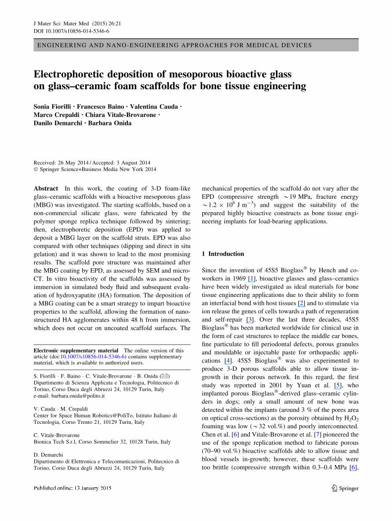
Figure 1a reports a SEM micrograph of a thermally-treated
SCNA scaffold, which is a successful replica of the porous
polymeric template. The strut architecture, with open and
interconnected macropores having size above 100 lm,
closely mimics the 3-D trabecular structure of human
cancellous bone [34]. The glass–ceramic nature of sintered
SCNA is confirmed by Fig. 1b, showing the micro-rough
appearance of a scaffold trabecula due to the presence of
needle-like crystals developed during the thermal treat-
ment. According to previous works, this crystalline phase
can be identified as CaSiO3 (wollastonite), as confirmed by
the compositional analysis (Fig. 1c).
Figure 2a, b shows SCNA scaffold after the EPD and
thermal treatment at lower and higher magnification,
respectively. At the micro-scale, scaffold pore walls and
21 Page 4 of 12 J Mater Sci: Mater Med (2015) 26:21
123
struts appear covered by a rather dense and uniform layer
of MBG micro-sized particles, without large agglomeration
occluding the macroporous structure. The corresponding
EDS spectrum is reported in Fig. 2c: besides the peaks of
silicon (Si) and calcium (Ca), also detected for the scaffold
as such, the signal due to phosphorus (P) is observed, as
expected on the basis of the MBG composition. Detection
of a signal due to phosphorus (P) is a clear evidence of the
incorporation of MBG particles inside the SCNA scaffold,
as the composition of the latter (57SiO2–34CaO–6Na2O–
3Al2O3 mol.%) does not imply the presence of P.
For the purpose of comparison, the results of the other
two (unsuccessful) strategies experimented in the attempt
to incorporate MBG inside the scaffold are illustrated in
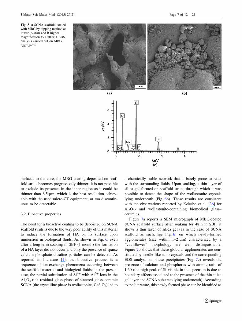
Figs. 3 and 4. Figure 3 shows SCNA scaffold after dipping
in MBG suspension: the macropores surface appears
mostly uncovered and quite large aggregates (about
20–30 lm) of MBG particles are observed in few cavities.
It appears that, through dipping approach, very low amount
of MBG can be loaded inside SCNA macropores and that
the few incorporated particles tend to assemble into cavi-
ties and coalesce during thermal treatment. EDS analysis
performed on these aggregates (Fig. 3c) shows, as in the
case of MBG incorporated by EPD, the presence of the
phosphorus (P) signal.
On the other hand, the strategy of submerging the
scaffold within the sol led to an excessive incorporation of
MBG, as shown in Fig. 4. Before calcination, the outer
surface of the scaffold was coated by a thick layer that
apparently obstructed the pores, which made undetectable
the macroporous network lying underneath. After the
thermal treatment, the problem persisted since a thick,
fragmented coating of MBG enveloped the SCNA scaffold
and occluded the macropores. Such a situation precludes
Fig. 1 SCNA scaffold as such:
a SEM micrograph of the
macroporous architecture
(9150); b detail of the
trabeculae characterized by a
surface micro-roughness due to
the presence of wollastonite
(CaSiO3) crystals (91,200);
c EDS analysis carried out on a
wollastonite crystal, confirming
the predominant presence of Si
and Ca (the presence of low
peaks of Na and Al, contained
in the residual amorphous
phase, is due to boundary
effects; the peak of Ag is due to
the ultrathin metal layer
deposited for SEM/EDS
analysis)
J Mater Sci: Mater Med (2015) 26:21 Page 5 of 12 21
123
any biomedical suitability of the device, as the scaffold
macropores would not be accessible by biological fluids.
Micro-CT investigations, carried out on the samples
processed by EPD, revealed that there was no difference
between SCNA scaffold as such and MBG-coated SCNA
scaffold in terms of total porosity (total pore contents of
50.9 and 51.6 vol.% were determined, respectively). These
findings are consistent with SEM observations, which
showed the presence of a thin MBG coating on scaffold
struts without pore occlusion. Density measurements sub-
stantially confirmed the assessments by micro-CT (mean
total porosities of 53.3 and 53.8 vol.% were found for the
scaffold as such and the MBG-coated scaffold, respec-
tively). Therefore, the deposition of a MBG thin coating on
scaffold struts via EPD does not involve decrement in the
scaffold porosity, that remains unaltered with respect to
non-coated samples.
The total porosity of the prepared constructs is within
the range recommended for bone tissue engineering scaf-
folds (50–80 vol. % [35] ), although very close to the lower
threshold. The scaffolds had good 3-D pores interconnec-
tivity throughout the whole volume with open porosity
calculated by CTAn software above 95 % of the overall
pores content, which is a key feature after in vivo
implantation in order to have paths for cells to migrate,
tissue to grow in and waste products to flow out.
Micro-CT was also used to assess in a non-destructive
way whether the coating was homogeneously and contin-
uously deposited on the struts throughout the scaffold
volume. The instrument available for the analysis exploited
a polychromatic X-ray radiation and, therefore, the dis-
crimination between materials with similar density (SCNA
and MBG) was quite difficult; however, after careful post-
processing of the reconstructed images, valuable results
have been obtained. Figure 5 reports the density mapping
along different cross-sections of a MBG-coated SCNA
scaffold depending on the different X-ray absorption of the
involved materials. The presence of MBG (green colour) is
clearly visible in the outer regions of the scaffold volume
(periphery), including both the zones underneath the scaf-
fold surfaces perpendicular to the EPD flow and the top and
bottom faces of the scaffold (planes parallel to the EPD
flow). In the micro-CT reconstructions, the scaffold core is
mainly characterized by the colour blue, which indicates
the presence of SCNA as the predominant material.
Therefore, we can propose that, moving from the outer
Fig. 2 a SCNA scaffold coated
with MBG by EPD at lower
(9670) and b higher
magnification (94,000); c EDS
analysis carried out on MBG
layer (the presence of low peaks
of Na and Al is due to boundary
effects of the SCNA substrate)
21 Page 6 of 12 J Mater Sci: Mater Med (2015) 26:21
123
surfaces to the core, the MBG coating deposited on scaf-
fold struts becomes progressively thinner; it is not possible
to exclude its presence in the inner region as it could be
thinner than 6.5 lm, which is the best resolution achiev-
able with the used micro-CT equipment, or too discontin-
uous to be detectable.
3.2 Bioactive properties
The need for a bioactive coating to be deposited on SCNA
scaffold struts is due to the very poor ability of this material
to induce the formation of HA on its surface upon
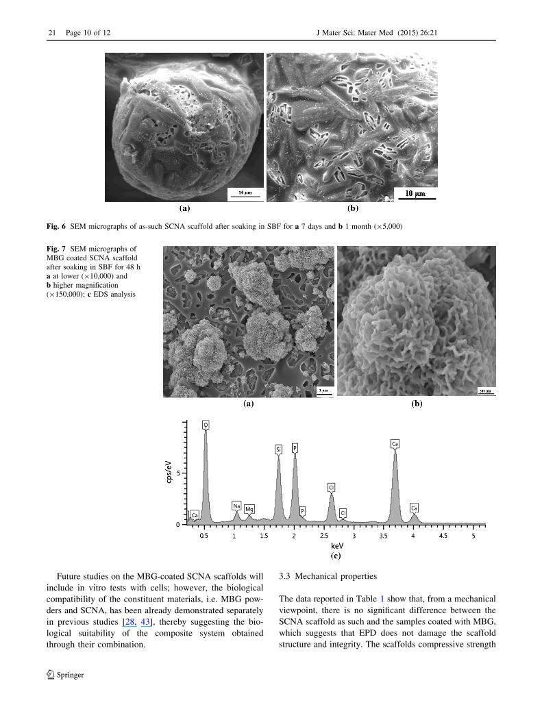
immersion in biological fluids. As shown in Fig. 6, even
after a long-term soaking in SBF (1 month) the formation
of a HA layer did not occur and only the presence of sparse
calcium phosphate ultrafine particles can be detected. As
reported in literature [1], the bioactive process is a
sequence of ion-exchange phenomena occurring between
the scaffold material and biological fluids; in the present
case, the partial substitution of Si4? with Al3? ions in the
Al2O3-rich residual glass phase of sintered glass–ceramic
SCNA (the crystalline phase is wollastonite, CaSiO3) led to
a chemically stable network that is barely prone to react
with the surrounding fluids. Upon soaking, a thin layer of
silica gel formed on scaffold struts, through which it was
possible to detect the shape of the wollastonite crystals
lying underneath (Fig. 6b). These results are consistent
with the observations reported by Kokubo et al. [36] for
Al2O3- and wollastonite-containing biomedical glass–
ceramics.
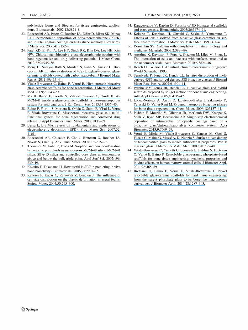
Figure 7a reports a SEM micrograph of MBG-coated
SCNA scaffold surface after soaking for 48 h in SBF: it
shows a thin layer of silica gel (as in the case of SCNA
scaffold as such, see Fig. 6) on which newly-formed
agglomerates (size within 1–2 lm) characterized by a
‘‘cauliflower’’ morphology are well distinguishable.
Figure 7b shows that these globular agglomerates are con-
stituted by needle-like nano-crystals, and the corresponding
EDS analysis on these precipitates (Fig. 7c) reveals the
presence of calcium and phosphorus with atomic ratio of
1.60 (the high peak of Si visible in the spectrum is due to
boundary effects associated to the presence of the thin silica
gel layer and SCNA substrate lying underneath). According
to the literature, this newly formed phase can be identified as
Fig. 3 a SCNA scaffold coated
with MBG by dipping method at
lower (9400) and b higher
magnification (91,500); c EDS
analysis carried out on MBG
aggregates
J Mater Sci: Mater Med (2015) 26:21 Page 7 of 12 21
123

HA: in fact, it is widely reported that precipitates of
Ca-deficient HA (Ca/P atomic ratio lower than 1.67, which is
the value for stoichiometric HA) with cauliflower mor-
phology typically form on the surface of bioactive glasses
upon soaking in SBF [10, 12], as actually observed in the
present work (Fig. 7). It is worth noting that the nano-crys-
talline nature of the HA formed on MBG-coated SCNA
scaffolds closely mimics the features of the biological apatite
of bones [37], whereas synthetic HA commonly used in
orthopaedics is characterized by larger grain size [38]. This
fact could have a significant impact on the in vivo perfor-
mance of the scaffold once implanted, as it is known that
surface nano-topography is a key factor in determining and
mediating cell-substrate interactions [38].
It is worth underlining that the MBG system, despite its
large silica content (80 mol.%), is highly bioactive. Hench
et al. [39] observed that, for conventional melt-derived
glasses, the silica content has to be 60 mol.% or less to
allow the bonding with bone. Nevertheless, it was dem-
onstrated that bone bonding can be attained with sol–gel
glasses with up to 90 mol.% of SiO2 because of their high
surface area (approximately two orders of magnitude
higher than that of melt-derived glasses), which allows
the surface reactivity to be emphasized [40, 41]. The
Fig. 4 Incorporation of MBG inside SCNA scaffolds by ‘‘forced’’
in situ gelation: SEM micrographs showing a part of the scaffold
(944) and b a surface detail before calcination (the SCNA scaffold is
completely enveloped by the gel, on which some cracks can be
observed); c sample surface after calcination (960) and d composi-
tional analysis (EDS) on the MBG fragmented calcined coating (the
peak of Ag is due to the ultrathin metal layer deposited for SEM/EDS
analysis)
21 Page 8 of 12 J Mater Sci: Mater Med (2015) 26:21
123

remarkable bioactive properties shown by MBG-coated
SCNA scaffold are also comparable with those previously
reported [28] for MBG membranes (with the same com-
position) upon soaking in SBF: also in that case, fast for-
mation of HA-like globular agglomerates was observed
after 48 h. This suggests that the open mesoporous struc-
ture is retained by the bioactive glass when deposited in
form of coating by EPD, playing a key role in determining
the performances of MBG-coated scaffold in SBF. This is
also supported by the evidence that the bioactive kinetics
observed for a non-porous bioactive glass coating (45S5
Bioglass�) deposited by EPD [42] on stainless steel sub-
strates, resulted slower compared to those reported in the
present work: in fact, the initial formation of sparse cal-
cium phosphate deposits (HA precursors) was reported to
occur after soaking for 5 days in SBF. In the present study,
the electrodeposited MBG coating undergoes partial dis-
solution upon soaking in SBF due to its high reactivity,
thereby accelerating the complex sequence of ion-
exchange phenomena which lead to the final formation of
HA agglomerates on the biomaterial surface (Fig. 7), as
described in detail by Hench et al. [2].
Fig. 5 Density mapping of MBG-coated SCNA scaffold by micro-CT:
a 3-D reconstruction of the central (approximately mid-length) cross-
sections along the [xy], [xz] and [yz] orthogonal planes and b corre-
sponding 2-D development; 3-D reconstruction of three cross-sections
along the [xy], [xz] and [yz] orthogonal planes and b corresponding 2-D
development obtained by placing the analysis plane perpendicular to
the EPD flow in a position close to the scaffold outer surface. Different
colours (blue and green) are associated to materials with different
absorption capacity towards the incident X-rays. Sample dimensions:
major size *8 mm; minor sizes *4 mm (Color figure online)
J Mater Sci: Mater Med (2015) 26:21 Page 9 of 12 21
123
Future studies on the MBG-coated SCNA scaffolds will
include in vitro tests with cells; however, the biological
compatibility of the constituent materials, i.e. MBG pow-
ders and SCNA, has been already demonstrated separately
in previous studies [28, 43], thereby suggesting the bio-
logical suitability of the composite system obtained
through their combination.
3.3 Mechanical properties
The data reported in Table 1 show that, from a mechanical
viewpoint, there is no significant difference between the
SCNA scaffold as such and the samples coated with MBG,
which suggests that EPD does not damage the scaffold
structure and integrity. The scaffolds compressive strength
Fig. 6 SEM micrographs of as-such SCNA scaffold after soaking in SBF for a 7 days and b 1 month (95,000)
Fig. 7 SEM micrographs of
MBG coated SCNA scaffold
after soaking in SBF for 48 h
a at lower (910,000) and
b higher magnification
(9150,000); c EDS analysis
21 Page 10 of 12 J Mater Sci: Mater Med (2015) 26:21
123

is above the standard reference range (2–12 MPa [39] )
considered for human trabecular bone as well as most of
foam-like scaffolds with the same porosity reported in the
literature [11]; therefore, the produced samples can be
proposed even for load-bearing applications like in joint
prostheses [13, 14]. The fracture energy is from one to two
orders of magnitude higher than that reported for other
glass–ceramic scaffolds produced by the same method and
having analogous macroporous architecture [44, 45]; in this
regard, a key role is played by the formulation of the
starting glass (SCNA) in affecting the sintering behaviour
of glass particles and the densification of the scaffold struts.
4 Conclusions
Glass–ceramic scaffolds, belonging to the SiO2–CaO–
Na2O–Al2O3 (SCNA) system, have been successfully
coated with mesoporous bioactive glass (MBG) by the
electrophoretic deposition technique. The MBG layer
appears rather dense and uniformly distributed throughout
the scaffold walls and struts, without occluding the mac-
roporous structure, as assessed by SEM and micro-CT
analyses. Alternative approaches to incorporate MBG, such
as dipping and in situ gelation, resulted unsuccessful. The
bioactivity of the MBG-coated SCNA has been assessed by
the formation of globular agglomerates of HA nano-crys-
tals after soaking for just 48 h in SBF, which were not
observed on SCNA scaffolds as such even after soaking for
longer periods. The mechanical properties of the MBG
coated-SCNA scaffold suggest their suitability as load-
bearing high-strength grafts for bone defect restoration;
furthermore, thanks to the combination of adequate
porosity, high mechanical strength and good bioactivity,
their use as smart components of joint prostheses could be
envisaged.
References
1. Hench LL. The story of Bioglass�. J Mater Sci Mater Med.
2006;17:967–78.
2. Hench LL, Splinter RJ, Allen WC, Greenlee TK. Bonding
mechanisms at the interface of ceramic prosthetic materials.
J Biomed Mater Res. 1971;5:117–41.
3. Hoppe A. Guldal, Boccaccini AR. A review of the biological
response to ionic dissolution products from bioactive glasses and
glass-ceramics. Biomaterials. 2011;32:2757–9.
4. Hench LL. Glass and glass-ceramic technologies to transform the
world. Int J Appl Glass Sci. 2011;2:162–76.
5. Yuan H, De Bruijn JD, Zhang X, Van Blitterswijk CA, De Groot
K. Bone induction by porous glass ceramic made from Bioglass�
(45S5). J Biomed Mater Res (Appl Biomater). 2001;58:270–6.
6. Chen Q, Thompson ID, Boccaccini AR. 45S5 Bioglass�-derived
glass-ceramic scaffolds for bone tissue engineering. Biomaterials.
2006;27:2414–25.
7. Vitale-Brovarone C, Verne E, Robiglio L, Appendino P, Bassi F,
Martinasso G, Canuto RA. Development of glass-ceramic scaf-
folds for bone tissue engineering: characterisation proliferation of
human osteobasts and nodule formation. Acta Biomater. 2007;3:
199–208.
8. Bellucci D, Chiellini F, Ciardelli G, Gazzarri M, Gentile P, Sola
A, Cannillo V. Processing and characterization of innovative
scaffold for bone tissue engineering. J Mater Sci Mater Med.
2012;23:1397–409.
9. Baino F, Ferraris M, Bretcanu O, Verne E, Vitale-Brovarone C.
Optimization of composition, structure and mechanical strength
of bioactive 3-D glass-ceramic scaffolds for bone substitution.
J Biomater Appl. 2013;27:872–90.
10. Gerhardt LC, Boccaccini AR. Bioactive glass and glass-ceramic
scaffolds for bone tissue engineering. Materials. 2010;3:
3867–910.
11. Baino F, Vitale-Brovarone C. Three-dimensional glass-derived
scaffolds for bone tissue engineering: current trends and forecasts
for the future. J Biomed Mater Res A. 2011;97:514–35.
12. Rahaman MN, Day DE, Bal BS, Fu Q, Jung SB, Bonewald LF.
Tomsia AP Bioactive glass in tissue engineering. Acta Biomater.
2011;7:2355–73.
13. Vitale-Brovarone C, Baino F, Tallia F, Gervasio C, Verne E.
Bioactive glass-derived trabecular coating: a smart solution for
enhancing osteointegration of prosthetic elements. J Mater Sci
Mater Med. 2012;23:2369–80.
14. Chen Q, Baino F, Pugno NM, Vitale-Brovarone C. Bonding
strength of glass-ceramic trabecular-like coatings to ceramic
substrates for prosthetic applications. Mater Sci Eng C. 2013;
33:1530–8.
15. Baino F, Vitale-Brovarone C. Mechanical properties and reli-
ability of glass-ceramic foam scaffolds for bone repair. Mater
Lett. 2014;118:27–30.
16. Wu C, Zhang Y, Zhu Y, Friis T, Xiao Y. Structure-property
relationships of silk-modified mesoporous bioglass scaffolds.
Biomaterials. 2010;31:3429–38.
17. Wu C, Fan W, Zhu Y, Gelinsky M, Chang J, Cuniberti G, Al-
brecht V, Friis T, Xiao Y. Multifunctional magnetic mesoporous
bioactive glass scaffolds with a hierarchical pore structure. Acta
Biomater. 2011;7:3563–72.
18. Boccaccini AR, Keim S, Ma R, Li Y, Zhitomirsky I. Electro-
phoretic deposition of biomaterials. J R Soc Interface. 2010;7:
S581–613.
19. Ducheyne P, Van Raemdonck W, Heughebaert JC, Heughebaert
M. Structural analysis of hydroxyapatite coatings on titanium.
Biomaterials. 1986;7:97–103.
20. Zhitomirsky I, Gal-Or L. Electrophoretic deposition of
hydroxyapatite. J Mater Sci Mater Med. 1997;8:213–9.
21. Krause D, Thomas B, Leinenbach C, Eifler D, Minay EJ, Boc-
caccini AR. The electrophoretic deposition of Bioglass particles
on stainless steel and Nitinol substrates. Surf Coating Technol.
2006;200:4835–45.
22. Roether JA, Boccaccini AR, Hench LL, Maquet V, Gautier S,
Jerome R. Development and in vitro characterisation of novel
bioresorbable and bioactive composite materials based on
Table 1 Mechanical properties of the prepared scaffolds
Sample rc (MPa) EV (9106 J m-3)
SCNA scaffold as-such 18.4 ± 3.7 1.5 ± 0.7
MBG-coated SCNA scaffold 19.7 ± 5.5 1.2 ± 0.7
J Mater Sci: Mater Med (2015) 26:21 Page 11 of 12 21
123
polylactide foams and Bioglass for tissue engineering applica-
tions. Biomaterials. 2002;18:3871–8.
23. Boccaccini AR, Peters C, Roether JA, Eifler D, Misra SK, Minay
EJ. Electrophoretic deposition of polyetheretherketone (PEEK)
and PEEK/Bioglass coatings on NiTi shape memory alloy wires.
J Mater Sci. 2006;41:8152–9.
24. Patel KD, El-Fiqi A, Lee HY, Singh RK, Kim DA, Lee HH, Kim
HW. Chitosan-nanobioactive glass electrophoretic coating with
bone regenerative and drug delivering potential. J Mater Chem.
2012;22:24945–56.
25. Meng D. Narayan Rath S, Mordan N, Salih V, Kneser U, Boc-
caccini AR. In vitro evaluation of 45S5 Bioglass�-derived glass-
ceramic scaffolds coated with carbon nanotubes. J Biomed Mater
Res A. 2011;99:435–44.
26. Vitale-Brovarone C, Baino F, Verne E. High strength bioactive
glass-ceramic scaffolds for bone regeneration. J Mater Sci Mater
Med. 2009;20:643–53.
27. Ma H, Baino F, Fiorilli S, Vitale-Brovarone C, Onida B. Al-
MCM-41 inside a glass-ceramic scaffold: a meso-macroporous
system for acid catalysis. J Eur Ceram Soc. 2013;33:1535–43.
28. Baino F, Fiorilli S, Mortera R, Onida O, Saino E, Visai L, Verne
E, Vitale-Brovarone C. Mesoporous bioactive glass as a multi-
functional system for bone regeneration and controlled drug
release. J Appl Biomater Funct Mater. 2012;10:12–21.
29. Besra L, Liu MA. review on fundamentals and applications of
electrophoretic deposition (EPD). Prog Mater Sci. 2007;52:
1–61.
30. Boccaccini AR, Chicatun F, Cho J, Bretcanu O, Roether JA,
Novak S, Chen Q. Adv Funct Mater. 2007;17:2815–22.
31. Thommes M, Kohn R, Froba M. Sorption and pore condensation
behavior of pure fluids in mesoporous MCM-48 silica, MCM-41
silica, SBA-15 silica and controlled-pore glass at temperatures
above and below the bulk triple point. Appl Surf Sci. 2002;196:
239–49.
32. Kokubo T, Takadama H. How useful is SBF in predicting in vivo
bone bioactivity? Biomaterials. 2006;27:2907–15.
33. Kenesei P, Kadar C, Rajkovits Z, Lendvai J. The influence of
cell-size distribution on the plastic deformation in metal foams.
Scripta Mater. 2004;50:295–300.
34. Karageorgiou V, Kaplan D. Porosity of 3D biomaterial scaffolds
and osteogenesis. Biomaterials. 2005;26:5474–91.
35. Kokubo T, Kushitani H, Ohtsuki C, Sakka S, Yamamuro T.
Effects of ions dissolved from bioactive glass-ceramics on sur-
face apatite formation. J Mater Sci Mater Med. 1993;4:1–4.
36. Dorozhkin SV. Calcium orthophosphates in nature, biology and
medicine. Materials. 2009;2:399–498.
37. Anselme K, Davidson P, Popa A, Giazzon M, Liley M, Ploux L.
The interaction of cells and bacteria with surfaces structured at
the nanometer scale. Acta Biomater. 2010;6:3824–46.
38. Hench LL, Wilson J. An introduction to bioceramics. Singapore:
World Scientific; 1993.
39. Sepulveda P, Jones JR, Hench LL. In vitro dissolution of melt-
derived 45S5 and sol-gel derived 58S bioactive glasses. J Biomed
Mater Res, Part A. 2002;61:301–11.
40. Pereira MM, Jones JR, Hench LL. Bioactive glass and hybrid
scaffolds prepared by sol-gel method for bone tissue engineering.
Adv Appl Ceram. 2005;104:35–42.
41. Lopez-Noriega A, Arcos D, Izquiendo-Barba I, Sakamoto Y,
Terasaki O, Vallet-Regi M. Ordered mesoporus bioactive glasses
for bone tissue regeneration. Chem Mater. 2006;18:3137–44.
42. Pishbin F, Mourino V, Gilchrist JB, McComb DW, Kreppel S,
Salih V, Ryan MP, Boccaccini AR. Single-step electrochemical
deposition of antimicrobial orthopaedic coatings based on a
bioactive glass/chitosan/nano-silver composite system. Acta
Biomater. 2013;9:7669–79.
43. Verne E, Miola M, Vitale-Brovarone C, Cannas M, Gatti S,
Fucale G, Maina G, Masse A, Di Nunzio S. Surface silver-doping
of biocompatible glass to induce antibacterial properties. Part I:
massive glass. J Mater Sci Mater Med. 2009;20:733–40.
44. Vitale-Brovarone C, Ciapetti G, Leonardi E, Baldini N, Bretcanu
O, Verne E, Baino F. Resorbable glass-ceramic phosphate-based
scaffolds for bone tissue engineering: synthesis, properties and
in vitro effects on human marrow stromal cells. J Biomater Appl.
2011;26:465–89.
45. Bretcanu O, Baino F, Verne E, Vitale-Brovarone C. Novel
resorbable glass-ceramic scaffolds for hard tissue engineering:
from the parent phosphate glass to its bone-like macroporous
derivatives. J Biomater Appl. 2014;28:1287–303.
21 Page 12 of 12 J Mater Sci: Mater Med (2015) 26:21
123
Related Documents


