Autothermal reforming:
a flexible syngas route with future potential
Dr. Klaus Noelker, Dr. Joachim Johanning, Uhde GmbH
Nitrogen + Syngas Conference, Bahrain
1 – 3 March 2010
2
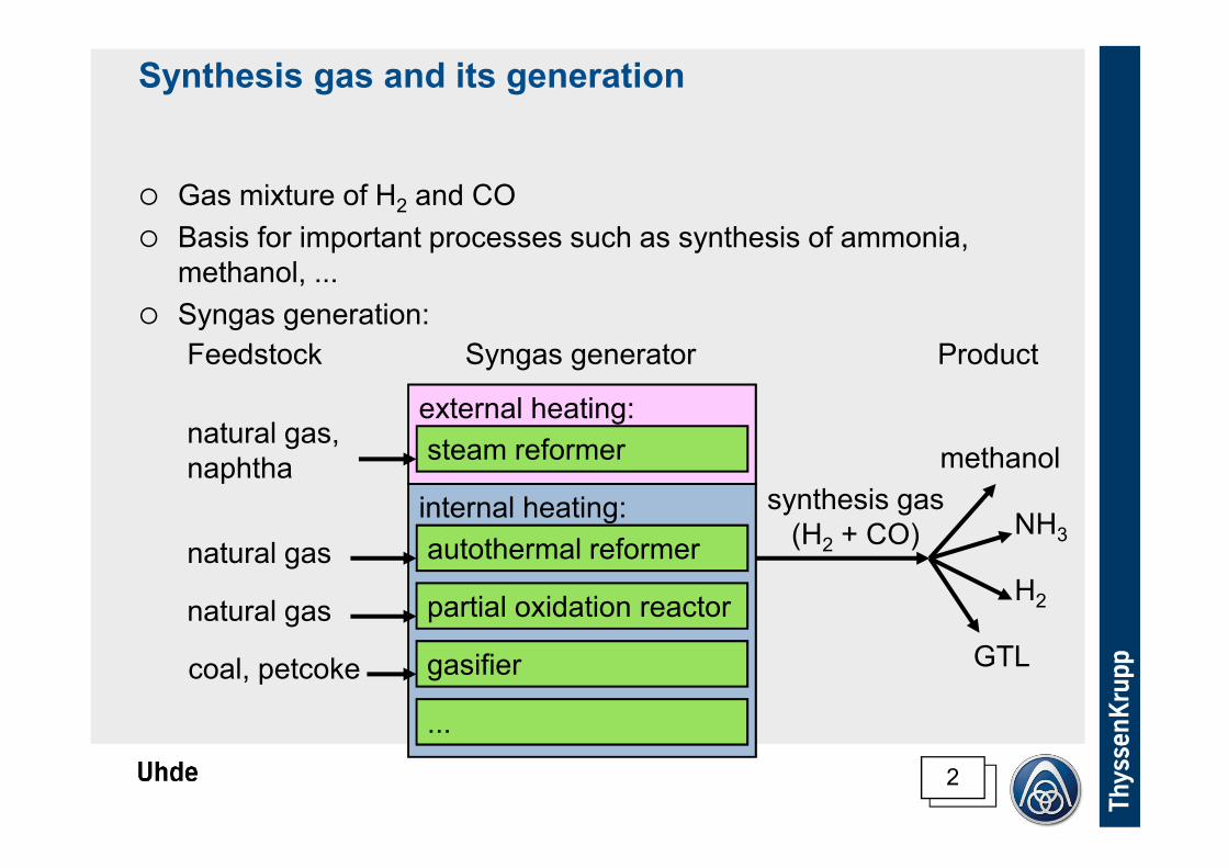
Synthesis gas and its generation
� Gas mixture of H2 and CO
� Basis for important processes such as synthesis of ammonia,
methanol, ...
� Syngas generation:
steam reformer
external heating:
internal heating:
gasifier
autothermal reformer
partial oxidation reactor
Syngas generator
...
Feedstock Product
synthesis gas
(H2 + CO)
methanol
NH3
GTL
H2
natural gas,
naphtha
natural gas
natural gas
coal, petcoke
3
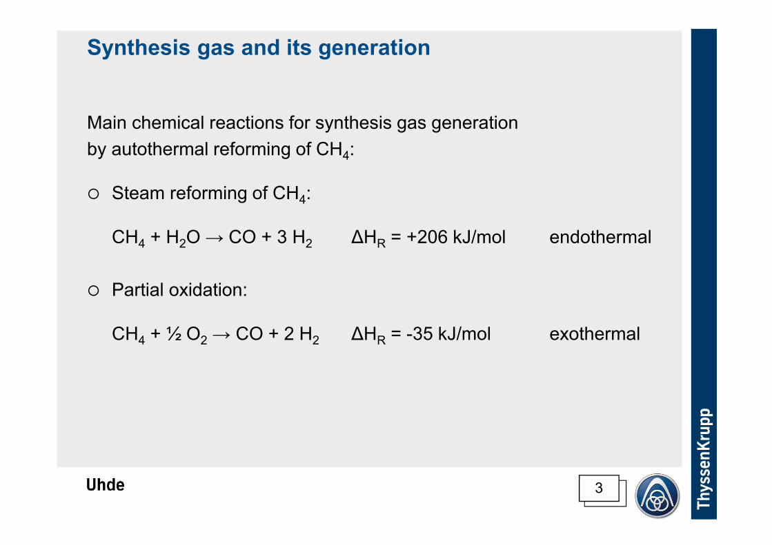
Synthesis gas and its generation
Main chemical reactions for synthesis gas generation
by autothermal reforming of CH4:
� Steam reforming of CH4:
CH4 + H2O → CO + 3 H2 ∆HR = +206 kJ/mol endothermal
� Partial oxidation:
CH4 + ½ O2 → CO + 2 H2 ∆HR = -35 kJ/mol exothermal

4
Synthesis gas composition
Synthesis gas composition requirements (outlet reformer):
� ammonia: (H2 + CO) / N2 ≈ 3.0
� methanol: (H2 – CO2) / (CO + CO2) ≈ 2.0
� hydrogen: H2 = max.
� gas to liquids: H2 / CO ≈ 2.0
Composition ranges provided:
steam reformer
ATR
gasifier
POX reactor
H2 : CO
1)
1)
0 1.0 2.0 3.0
1)
combined reforming
Note 1) possible gas
compositions via CO
conversion of the
syngas
5
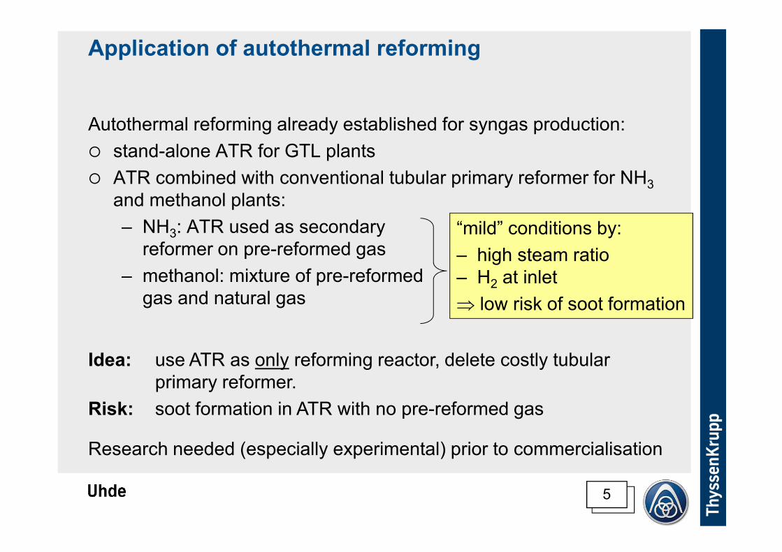
Application of autothermal reforming
Autothermal reforming already established for syngas production:
� stand-alone ATR for GTL plants
� ATR combined with conventional tubular primary reformer for NH3
and methanol plants:
– NH3: ATR used as secondary
reformer on pre-reformed gas
– methanol: mixture of pre-reformed
gas and natural gas
“mild” conditions by:
– high steam ratio
– H2 at inlet
⇒ low risk of soot formation
Idea: use ATR as only reforming reactor, delete costly tubular
primary reformer.
Risk: soot formation in ATR with no pre-reformed gas
Research needed (especially experimental) prior to commercialisation

6
Flowsheet options for ATR based NH3 plant
Different oxidator compositions possible
⇒ different flowsheets for syngas generation of an NH3 plant possible
Oxidator
plain air
(21 % O2)
enriched air
pure O2
Oxygen demand
defined by heat
demand of the
reforming
reaction
Nitrogen content compared
to demand of NH3 synthesis
too high
matching
too low

7
Flowsheet options for ATR based NH3 plant
Option 1: Plain air as oxidator
ATR gas
cooling
CO
conv.CO2
removal
cold
box
NH3
synth.
air
waste gas
steam steam
Gas composition: large N2 surplus in syngas
Consequence: either cryogenic unit to remove N2
or large purge gas stream
Size: largest flowrates and equipment sizes in front end
natural
gas

8
Flowsheet options for ATR based NH3 plant
Option 2: Oxygen enriched air as oxidator
Gas composition: correct amount of N2 for NH3 synthesis
Consequence: need air separation unit
Size: medium
ATR gas
cooling
CO
conv.
metha-
nation
NH3
synth.
natural
gas
air air sep.
plant
purge
treatm.
oxygen + nitrogen
steam steam
CO2
removal
9
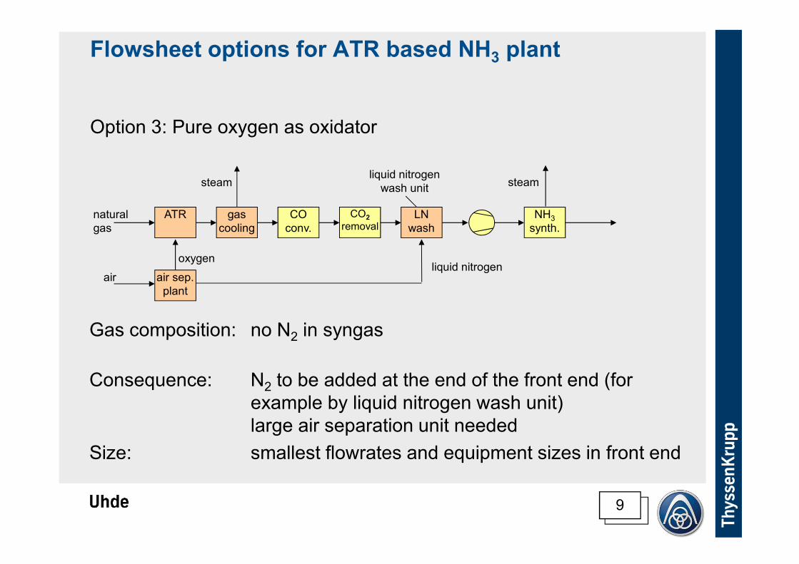
Flowsheet options for ATR based NH3 plant
Option 3: Pure oxygen as oxidator
Gas composition: no N2 in syngas
Consequence: N2 to be added at the end of the front end (for
example by liquid nitrogen wash unit)
large air separation unit needed
Size: smallest flowrates and equipment sizes in front end
ATR gas
cooling
CO
conv.
CO2
removalLN
wash
NH3
synth.
natural
gas
air air sep.
plant
liquid nitrogenoxygen
steam steamliquid nitrogen
wash unit

10
Flowsheet options for ATR based NH3 plant
Economic comparison between 3 options
� Operating cost:
Similar (similar energy consumption)
� Investment cost:
Option 3 (pure oxygen) seems to be most expensive:
– large air separation unit
– nitrogen wash unit

11
Economic comparison between steam reformer and
ATR plant
Operating cost (energy consumption)
steam reformer ATR
basis heat of reaction supplied by burning feed gas
⇒ higher feed gas flow
⇒ higher energy demand for preheating
lower loss from flue gas
air separation
Overall:
+ 6 % cost for option “enriched air”
+ 10 % cost for option “pure oxygen”

12
Economic comparison between steam reformer and
ATR plant
Investment cost judgement difficult because no purely on
ATR based NH3 plant built so far
steam reformer ATR
basis air separation
no steam reformer
~ ATR similar to secondary reformer
liquid nitrogen wash unit (option “pure oxygen”)
no H2 recovery unit (option “pure oxygen”)
Overall:
+ / – ??? ⇒ evaluation on next slide
biggest contributors

13
Economic comparison between steam reformer and
ATR plant
Investment cost
Most significant effect comes from cost relation of air separation and
steam reformer
steam reformer: cost
almost linear with
capacity (no significant
“economy of scale”)
0 2,000 4,000 6,000 8,000
ammonia capacity (mtpd)
rela
tive
in
ve
stm
en
t co
st
cost range of air
separation unit
⇒ Lower cost of air
separation unit at
high plant capacities
⇒ Lower cost for ATR
14
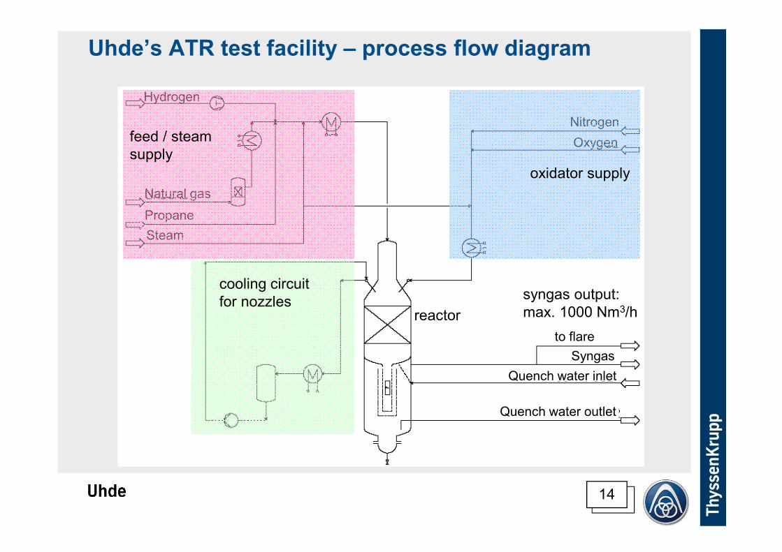
Uhde’s ATR test facility – process flow diagram
Natural gas
Propane
Steam
Quench water outlet
Quench water inlet
Syngas
Oxygen
Nitrogen
to flare
Hydrogen
syngas output:
max. 1000 Nm3/h
feed / steam
supply
oxidator supply
cooling circuit
for nozzlesreactor
15
Uhde’s ATR test facility
Aus Datenschutzgründen wurde das automatische Herunterladen dieses Bilds von PowerPoint gesperrt.
16
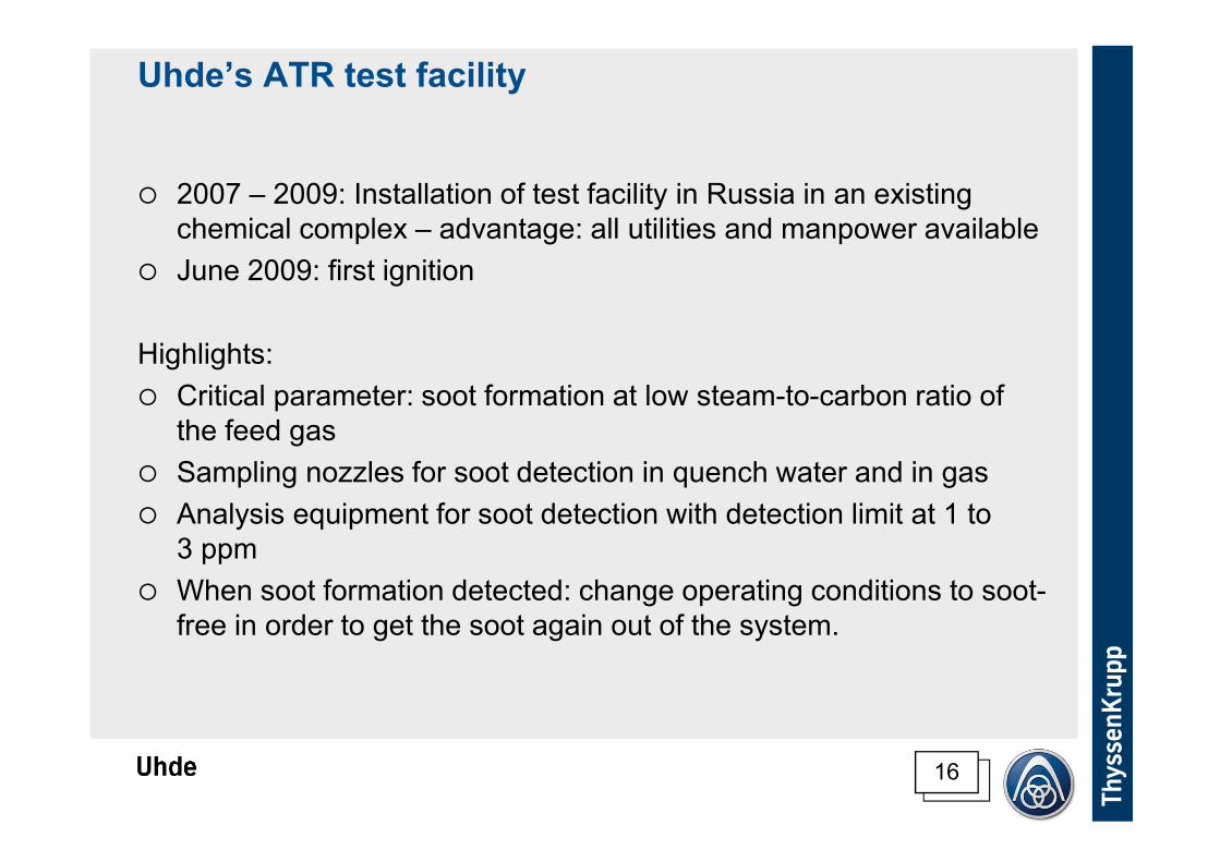
Uhde’s ATR test facility
� 2007 – 2009: Installation of test facility in Russia in an existing
chemical complex – advantage: all utilities and manpower available
� June 2009: first ignition
Highlights:
� Critical parameter: soot formation at low steam-to-carbon ratio of
the feed gas
� Sampling nozzles for soot detection in quench water and in gas
� Analysis equipment for soot detection with detection limit at 1 to
3 ppm
� When soot formation detected: change operating conditions to soot-
free in order to get the soot again out of the system.

17
Test programme for the ATR
Outlet gas requirements:
� composition (e.g. [CO + H2] / N2 ≈ 3.0 or H2 : CO ≈ 2.0; no soot)
Design parameters:
� combustion zone geometry, nozzles etc.
� combustion zone gas residence time
� inlet velocity feed/steam mixture
� inlet velocity oxidator
� space velocity catalyst bed
Operating parameters:
� steam-to-carbon ratio
� combustion zone temperature
(by oxygen-to-carbon ratio)
� oxidator composition
Can be varied by operation of
the test facility
Target of the optimisation:
� highest CH4 conversion
� minimum oxygen consumption
18
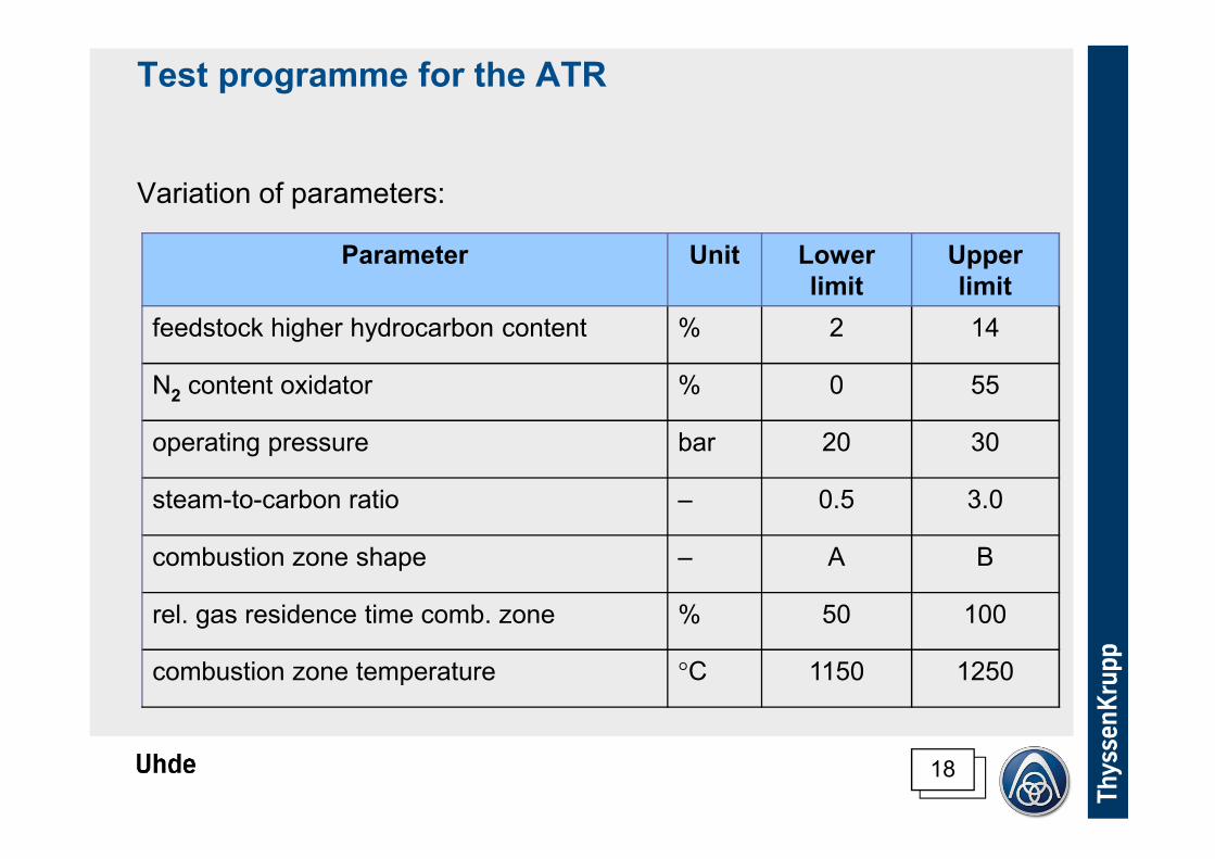
Test programme for the ATR
Variation of parameters:
Parameter Unit Lower
limit
Upper
limit
feedstock higher hydrocarbon content % 2 14
N2 content oxidator % 0 55
operating pressure bar 20 30
steam-to-carbon ratio – 0.5 3.0
combustion zone shape – A B
rel. gas residence time comb. zone % 50 100
combustion zone temperature °C 1150 1250
19
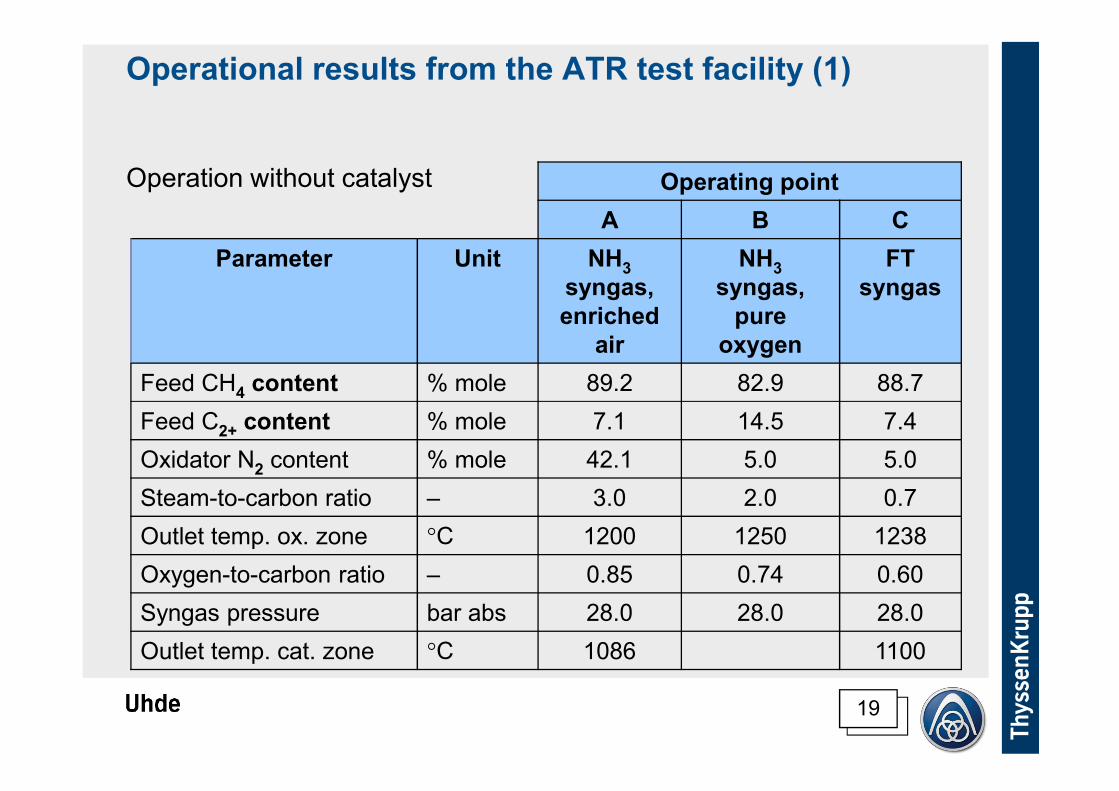
Operational results from the ATR test facility (1)
Operation without catalyst Operating point
A B C
Parameter Unit NH3
syngas,
enriched
air
NH3
syngas,
pure
oxygen
FT
syngas
Feed CH4 content % mole 89.2 82.9 88.7
Feed C2+ content % mole 7.1 14.5 7.4
Oxidator N2 content % mole 42.1 5.0 5.0
Steam-to-carbon ratio – 3.0 2.0 0.7
Outlet temp. ox. zone °C 1200 1250 1238
Oxygen-to-carbon ratio – 0.85 0.74 0.60
Syngas pressure bar abs 28.0 28.0 28.0
Outlet temp. cat. zone °C 1086 1100
20
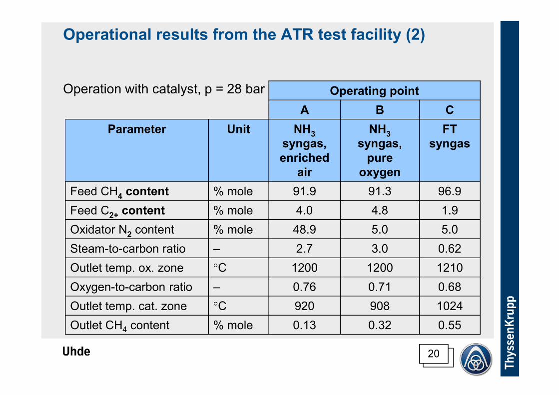
Operating point
A B C
Parameter Unit NH3
syngas,
enriched
air
NH3
syngas,
pure
oxygen
FT
syngas
Feed CH4 content % mole 91.9 91.3 96.9
Feed C2+ content % mole 4.0 4.8 1.9
Oxidator N2 content % mole 48.9 5.0 5.0
Steam-to-carbon ratio – 2.7 3.0 0.62
Outlet temp. ox. zone °C 1200 1200 1210
Oxygen-to-carbon ratio – 0.76 0.71 0.68
Outlet temp. cat. zone °C 920 908 1024
Outlet CH4 content % mole 0.13 0.32 0.55
Operational results from the ATR test facility (2)
Operation with catalyst, p = 28 bar
21
Summary
� Autothermal reformers well established in combination with other
syngas generators like tubular reformers (“conventional concept”)
� Cost advantage of conventional concept vs. stand-alone ATR
shrinking at higher plant capacity
� Research work triggered by less experience with stand-alone ATR
� Uhde’s test facility built and in operation
� Operating data used to identify best design and to tune the design
tools for commercial applications
� Uhde will be ready to offer an ATR for NH3 and other applications in
the near future

22
Summary
Thank you for your attention!
Questions please!