Solar thermal reforming of methane feedstocks for hydrogen and syngas production—A review Christos Agrafiotis n , Henrik von Storch, Martin Roeb, Christian Sattler Deutsches Zentrum für Luft- und Raumfahrt/German Aerospace Center—DLR, Linder Höhe, 51147 Köln, Germany article info Article history: Received 31 January 2013 Received in revised form 26 July 2013 Accepted 11 August 2013 Available online 26 September 2013 Keywords: Methane Reforming Hydrogen Syngas Solar thermal Solar reactors abstract It is currently accepted that at least for a transition period, solar-aided reforming of methane-containing gaseous feedstocks with natural gas (NG) being the first choice, can offer a viable route for fossil fuel decarbonization and create a transition path towards a “solar hydrogen- solar fuels” economy. Both industrially established traditional reforming concepts, steam and dry/carbon dioxide reforming, being highly endothermic can be rendered solar-aided and thus offer in principle a real possibility to lower the cost for introducing renewable hydrogen production technologies to the market by a combination of fossil fuels and solar energy. They also share similar technical issues considering linking of their key thermochemistry and thermodynamics to efficient exploitation of solar energy. In this perspective, the current article presents the development and current status of solar-aided reforming of gaseous methane-containing feedstocks, focussing in particular on the reactor technologies and concepts employed so far to couple the heat requirements of the methane reforming process to the underlying principles, intricacies and peculiarities of concentrated solar power (CSP) exploitation. A thorough literature review is presented, addressing practically the whole scale of solar reactors employed so far: from small-scale reactor prototypes often tested under simulated solar irradiation up to scaled-up reformer reactors tested on solar platform sites at the level of few hundreds of kilowatts. Having presented the current state-of-the-art of the technology, topics for future work are suggested and issues to help further commercialization are addressed. & 2013 Elsevier Ltd. All rights reserved. Contents 1. Introduction ........................................................................................................ 656 2. Hydrogen production via reforming of methane feedstocks .................................................................. 659 2.1. Thermochemistry and thermodynamics of reforming ................................................................. 659 2.2. Current industrial status ........................................................................................ 660 3. Solar-aided reforming ................................................................................................ 662 3.1. Solar concentration systems ..................................................................................... 662 3.2. Coupling reforming with solar energy: Solar receiver–reactor concepts .................................................. 662 3.3. Worldwide research in solar thermal reforming of gaseous feedstocks ................................................... 667 3.3.1. Solar thermal reforming of methane ....................................................................... 667 3.3.2. Solar thermal reforming of biogas ......................................................................... 679 4. Current development status and future prospects.......................................................................... 679 References ............................................................................................................. 680 1. Introduction Hydrogen (H 2 ) has a long tradition as an energy carrier and as an important “raw material” in chemical industries and refineries. Hydrogen can be produced from a variety of feedstocks, gaseous, liquid and solid, including fossil fuels such as natural gas, oil and coal respectively, as well as renewable such as biomass and Contents lists available at ScienceDirect journal homepage: www.elsevier.com/locate/rser Renewable and Sustainable Energy Reviews 1364-0321/$ - see front matter & 2013 Elsevier Ltd. All rights reserved. http://dx.doi.org/10.1016/j.rser.2013.08.050 n Corresponding author. Tel.: þ49 22036014132; fax: þ49 22036014072. E-mail addresses: christos.agrafi[email protected], christos.agrafi[email protected] (C. Agrafiotis). Renewable and Sustainable Energy Reviews 29 (2014) 656–682

Welcome message from author
This document is posted to help you gain knowledge. Please leave a comment to let me know what you think about it! Share it to your friends and learn new things together.
Transcript
Solar thermal reforming of methane feedstocks for hydrogenand syngas production—A review
Christos Agrafiotis n, Henrik von Storch, Martin Roeb, Christian SattlerDeutsches Zentrum für Luft- und Raumfahrt/German Aerospace Center—DLR, Linder Höhe, 51147 Köln, Germany
a r t i c l e i n f o
Article history:Received 31 January 2013Received in revised form26 July 2013Accepted 11 August 2013Available online 26 September 2013
Keywords:MethaneReformingHydrogenSyngasSolar thermalSolar reactors
a b s t r a c t
It is currently accepted that at least for a transition period, solar-aided reforming of methane-containinggaseous feedstocks with natural gas (NG) being the first choice, can offer a viable route for fossil fueldecarbonization and create a transition path towards a “solar hydrogen- solar fuels” economy. Bothindustrially established traditional reforming concepts, steam and dry/carbon dioxide reforming, beinghighly endothermic can be rendered solar-aided and thus offer in principle a real possibility to lower thecost for introducing renewable hydrogen production technologies to the market by a combination offossil fuels and solar energy. They also share similar technical issues considering linking of their keythermochemistry and thermodynamics to efficient exploitation of solar energy. In this perspective,the current article presents the development and current status of solar-aided reforming of gaseousmethane-containing feedstocks, focussing in particular on the reactor technologies and conceptsemployed so far to couple the heat requirements of the methane reforming process to the underlyingprinciples, intricacies and peculiarities of concentrated solar power (CSP) exploitation. A thoroughliterature review is presented, addressing practically the whole scale of solar reactors employed so far:from small-scale reactor prototypes often tested under simulated solar irradiation up to scaled-upreformer reactors tested on solar platform sites at the level of few hundreds of kilowatts. Havingpresented the current state-of-the-art of the technology, topics for future work are suggested and issuesto help further commercialization are addressed.
& 2013 Elsevier Ltd. All rights reserved.
Contents
1. Introduction . . . . . . . . . . . . . . . . . . . . . . . . . . . . . . . . . . . . . . . . . . . . . . . . . . . . . . . . . . . . . . . . . . . . . . . . . . . . . . . . . . . . . . . . . . . . . . . . . . . . . . . . 6562. Hydrogen production via reforming of methane feedstocks . . . . . . . . . . . . . . . . . . . . . . . . . . . . . . . . . . . . . . . . . . . . . . . . . . . . . . . . . . . . . . . . . . 659
2.1. Thermochemistry and thermodynamics of reforming . . . . . . . . . . . . . . . . . . . . . . . . . . . . . . . . . . . . . . . . . . . . . . . . . . . . . . . . . . . . . . . . . 6592.2. Current industrial status . . . . . . . . . . . . . . . . . . . . . . . . . . . . . . . . . . . . . . . . . . . . . . . . . . . . . . . . . . . . . . . . . . . . . . . . . . . . . . . . . . . . . . . . 660
3. Solar-aided reforming . . . . . . . . . . . . . . . . . . . . . . . . . . . . . . . . . . . . . . . . . . . . . . . . . . . . . . . . . . . . . . . . . . . . . . . . . . . . . . . . . . . . . . . . . . . . . . . . 6623.1. Solar concentration systems . . . . . . . . . . . . . . . . . . . . . . . . . . . . . . . . . . . . . . . . . . . . . . . . . . . . . . . . . . . . . . . . . . . . . . . . . . . . . . . . . . . . . 6623.2. Coupling reforming with solar energy: Solar receiver–reactor concepts . . . . . . . . . . . . . . . . . . . . . . . . . . . . . . . . . . . . . . . . . . . . . . . . . . 6623.3. Worldwide research in solar thermal reforming of gaseous feedstocks . . . . . . . . . . . . . . . . . . . . . . . . . . . . . . . . . . . . . . . . . . . . . . . . . . . 667
3.3.1. Solar thermal reforming of methane . . . . . . . . . . . . . . . . . . . . . . . . . . . . . . . . . . . . . . . . . . . . . . . . . . . . . . . . . . . . . . . . . . . . . . . 6673.3.2. Solar thermal reforming of biogas . . . . . . . . . . . . . . . . . . . . . . . . . . . . . . . . . . . . . . . . . . . . . . . . . . . . . . . . . . . . . . . . . . . . . . . . . 679
4. Current development status and future prospects. . . . . . . . . . . . . . . . . . . . . . . . . . . . . . . . . . . . . . . . . . . . . . . . . . . . . . . . . . . . . . . . . . . . . . . . . . 679References . . . . . . . . . . . . . . . . . . . . . . . . . . . . . . . . . . . . . . . . . . . . . . . . . . . . . . . . . . . . . . . . . . . . . . . . . . . . . . . . . . . . . . . . . . . . . . . . . . . . . . . . . . . . . 680
1. Introduction
Hydrogen (H2) has a long tradition as an energy carrier and asan important “raw material” in chemical industries and refineries.Hydrogen can be produced from a variety of feedstocks, gaseous,liquid and solid, including fossil fuels such as natural gas, oil andcoal respectively, as well as renewable such as biomass and
Contents lists available at ScienceDirect
journal homepage: www.elsevier.com/locate/rser
Renewable and Sustainable Energy Reviews
1364-0321/$ - see front matter & 2013 Elsevier Ltd. All rights reserved.http://dx.doi.org/10.1016/j.rser.2013.08.050
n Corresponding author. Tel.: þ49 22036014132; fax: þ49 22036014072.E-mail addresses: [email protected],
[email protected] (C. Agrafiotis).
Renewable and Sustainable Energy Reviews 29 (2014) 656–682
water [1]. Virtually all hydrogen produced today is sourced fromfossil fuels, with the principal method employed being thecatalytic reforming of methane (CH4, the principal component ofnatural gas and other gaseous fuels such as landfill or coal seamgas). Two different reactions can be distinguished in the methanereforming process: steam methane reforming (SMR) and CO2
(or dry) methane reforming (DMR), represented by the followingEqs. (1) and (2), respectively:
CH4 þH2O⇆3H2þCO ΔH0298 K ¼ þ206 kJ=mol ð1Þ
CH4 þCO2⇆2H2þ2CO ΔH0298 K ¼ þ247 kJ=mol ð2Þ
Both these reactions are highly endothermic, therefore the heat-ing value of the product is greater than the heating value of thereactants and both reactions are favored by high temperatures(industrial reforming processes are carried out between 800 and1000 1C) [1]. The required energy is supplied by combustion ofadditional natural gas and process waste gas (tail gas) from thedownstream hydrogen purification step. The share of natural gas,consumed as fuel, varies from 3% to 20% of the total natural gasconsumption of the plant, depending on the subsequent energyrequirements of downstream processes (e.g. CO2 removal) [2]. Thereaction gas product mixture is known with the name Synthesis Gas
(syngas). Syngas is a gas mixture that contains varying amounts ofCO and H2 whose exothermic conversion to fuel and other productshas been commercially practiced since a long time ago e.g. via theFischer–Tropsch technology and which can be also used as a sourceof pure hydrogen and carbon monoxide [3,4]. In fact Hydrogen andsyngas are the basic raw materials to produce synthetic liquid fuels(SLF) and chemicals via industrially available processes.
There are additional ways to produce hydrogen and/or syngas;e.g. from biomass processing, coal gasification, other hydrocarbons,etc. Whilst reforming is likely to remain the technology of choice forsome time, hydrogen is ultimately seen to be the clean fuel of thefuture and will need to be produced entirely from renewable orcarbon-neutral energy i.e. with energy input from sunlight, wind,hydropower or nuclear energy [5]. In this perspective, the harnessingof the huge energy potential of solar radiation and its effectiveconversion to hydrogen becomes a subject of primary technologicalinterest. There are basically three pathways for producing Hydrogenwith the aid of solar energy [6,7]: electrochemical, photochemicaland thermochemical. The latter is based on the use of concentratedsolar power (CSP) radiation as the energy source for performinghigh-temperature reactions that produce Hydrogen – in many casesfirst via syngas – from transformation of various fossil and non-fossilfuels via different routes such as water splitting (to produce
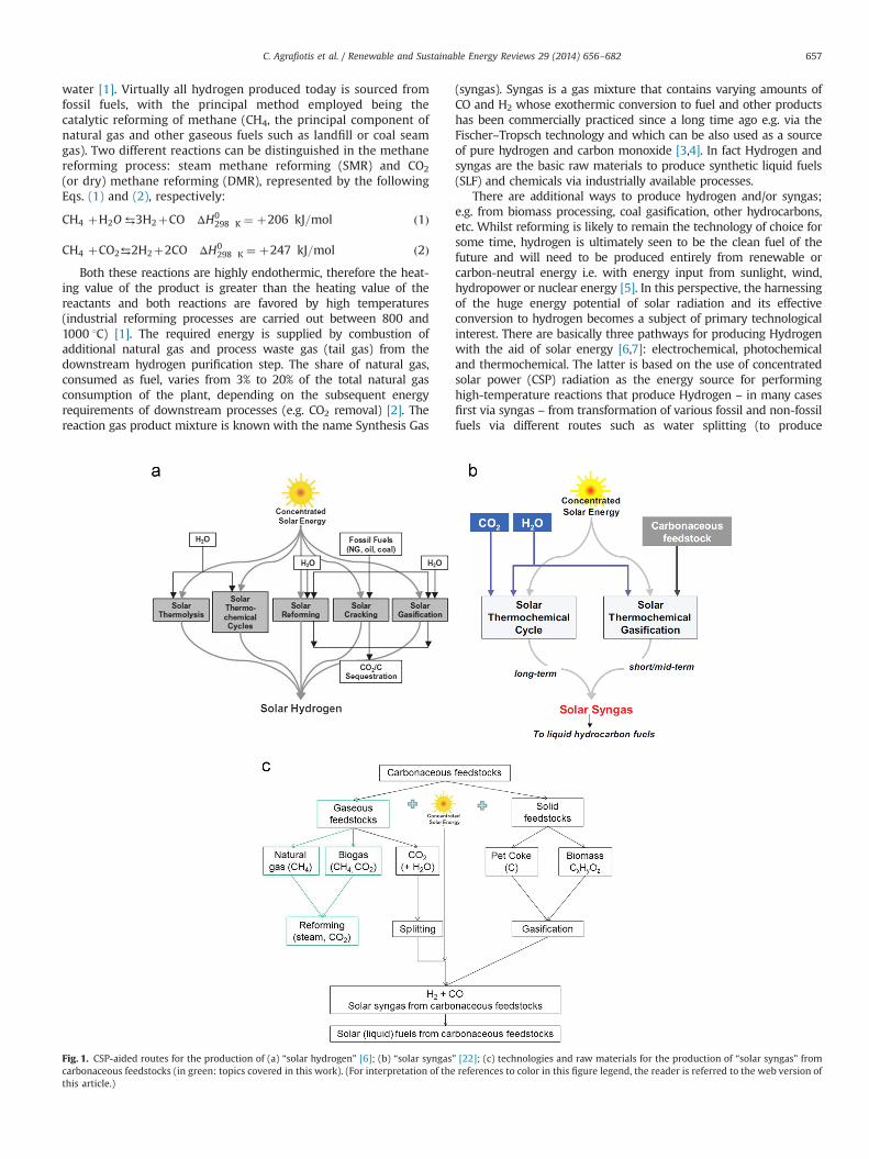
Fig. 1. CSP-aided routes for the production of (a) “solar hydrogen” [6]; (b) “solar syngas” [22]; (c) technologies and raw materials for the production of “solar syngas” fromcarbonaceous feedstocks (in green: topics covered in this work). (For interpretation of the references to color in this figure legend, the reader is referred to the web version ofthis article.)
C. Agrafiotis et al. / Renewable and Sustainable Energy Reviews 29 (2014) 656–682 657
hydrogen and oxygen) [8–10], natural gas steam reforming (toproduce syngas) [11–13], natural gas cracking (to produce hydrogenand carbon black nanoparticles) [14–17] and gasification of solidcarbonaceous materials like coal or biomass (to produce syngas) [18–20]. All of these routes involve in some step endothermic reactionsthat can make use of concentrated solar radiation as their energysource of high-temperature process heat. When solar energy isemployed as the energy source for the production of the rawmaterials for the synthesis of fuels, the latter are characterized withthe term “solar fuels”. In the broad sense this term can contain inaddition to “solar hydrogen”, synthetic liquid hydrocarbons andalcohols that are produced from reactions between H2 and CO thathave originated from solar-aided dissociation processes (depicted inFig. 1) as well as metal powders that can be obtained by solarthermal reduction of metal oxides [21]. The various CSP-aided “solarhydrogen” production routes are shown schematically in Fig. 1a [6]and those for “solar syngas” in Fig. 1b [22]. A further elaboration ofthe latter case, showing in greater detail the various raw materialsand routes for CSP-aided production of “solar syngas” is depicted inFig. 1c.
Obviously, the ideal raw material for Hydrogen production iswater, due to its abundance, low price and the absence of CO2
emissions during its dissociation to hydrogen and oxygen. However,its single-step thermal dissociation (known as water thermolysis—Fig. 1a), although conceptually simple, requires temperatures inexcess of 2200 1C for obtaining some significant dissociation degree[8]. On the other hand solar-aided water splitting by thermoche-mical cycles – a series of chemical steps by which the net result isthe splitting of water into hydrogen and oxygen at lower tempera-tures – even though demonstrated experimentally on a pilot-solar-plant level [23], still has to resolve some technical barriers to reachfull technical maturity for large scale implementation.
Therefore, at least for a transition period, hydrogen supply at acompetitive cost can only be achieved from hydrocarbons—essen-tially natural gas (whose principal component is methane) usingwell-known commercial processes like steam reforming wheremethane and steam are converted to syngas. As an intermediatestep, considerable effort is being spent on developing a hybridhydrogen technology in which concentrated solar thermal energyis used to provide the heat for the high temperature endothermicsteam–methane reforming reaction. In doing so, solar energy isembodied thermochemically in the product hydrogen. This over-comes many of the limitations of solar energy, enabling it to bestored at ambient conditions, transported from the point ofcollection to where it is required and enabling it to be usedoutside daylight hours. Such a transitional technology is consid-ered by many to be an essential stepping stone from currentpractice to a truly renewable-based hydrogen economy [21,24].
Another promising application for solar reforming is the exploi-tation of remote natural gas resources, with high carbon-dioxidecontent. These sources can usually not be exploited economically asconventional natural gas resources, due to high costs for purifica-tion and transport. Since solar dry- or mixed-reforming (reactionof the natural gas source with a mixture of water and CO2) of thesenatural gas resources yields a syngas appropriate for furtherconversion into liquid fuels, this states an attractive possibility for
future exploitation of these resources. These liquid fuels can easilybe transported and utilized as transportation fuel in of energydemanding regions of the world (e.g. Europe or Japan). The mostpromising liquid fuels to be generated from solar syngas aremethanol, dimethyl ether (DME) and Fischer–Tropsch diesel. Forthe described application Fischer–Tropsch diesel has two majoradvantages: It has the highest volumetric energy density of thesefuels (which is advantageous for ocean transport) and it can beprocessed and utilized as pure or blend-in fuel without modifica-tion to either fuel distribution equipment or engines [25]. The majordisadvantage of Fischer–Tropsch Diesel in this context is the lowselectivity towards diesel: in Fischer–Tropsch synthesis a variety ofhydrocarbons is produced and complex measures have to be takento increase the yield of diesel fuel [26,27]. DME is, in commercialproduction plants produced via further processing of methanol,though a number of single step processes for direct production ofDME from syngas are being developed. DME can easily be dis-tributed utilizing LPG infrastructure and can be utilized in combus-tion engines as diesel substitute without modification to the engineitself. Modifications are necessary to the fuel delivery system, suchas pumps and injector. A major advantage of DME compared tomethanol is, that it is considered environmentally benign andrelatively harmless considering health concerns [28]. Methanolcan be used as a blend-in fuel in conventional fuels, for exampleas M85 (85% methanol, 15% unleaded gasoline) with minor mod-ifications to the engine. Though, a major prospect for broadutilization of methanol is the development of the direct methanolfuel cell (DMFC) to a commercial status for utilization in transporta-tion and substitute for batteries in mobile applications, such asmobile phones and laptop computers [29]. Furthermore methanolcan be utilized as fuel for PEM fuel cells with previous on-boardreforming to hydrogen [29,30]. This possibility has the advantage ofeasier transport and handling of the fuel, compared to the utiliza-tion of pure hydrogen. For all three of these liquid fuels, there is abroad range of applications with minor barriers to overcome,regarding the utilization. On the other hand, the production coupledto a solar reforming plant has not been realized yet and theintermittent character of solar energy supply makes a directadoption of conventional steady-state process layouts difficult.Therefore the main task to do before being able to commercializethe production of liquid fuels via solar reforming of natural gas is athorough investigation of the dynamic behaviour of the associatedproduction process.
Methane is the most abundant hydrocarbon and it also has thehighest hydrogen content. Water is also rich in hydrogen andtherefore the steam/methane reforming reaction is the preferredreaction for hydrogen production. However, in addition to naturalgas, there are plenty of other promising methane-containing gasesfor hydrogen production, e.g. in refineries and steel productionplants such as coke oven gas, refinery gas and biogas, with theircomposition, though, varying notably depending on their source.Coke is an essential input to the iron-making process and isproduced by heating coal in coke ovens. Coke oven gas isgenerated as a by-product of the process and it consists amongothers hydrogen, methane and carbon monoxide. Refinery gas isdefined as non-condensable gas obtained during distillation of
Pre-treatment(Desulphurization +
Pre-reforming)
HCFeed Catalytic
SteamReforming
CH4 Water-Gas-ShiftReaction
Steam Steam
Gas Separationby PSA
H2/CO2/CO Hydrogen
Fuel
H2/CO
(Syngas)
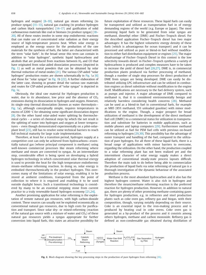
Fig. 2. Block diagram showing the key processing steps in the production of pure hydrogen from reforming [31].
C. Agrafiotis et al. / Renewable and Sustainable Energy Reviews 29 (2014) 656–682658
crude oil in refineries. Mainly it consists of hydrogen, methaneand ethane. Landfill gas or biogas is a product of the anaerobicdigestion or fermentation of biodegradable materials, comprisedprimarily of methane and carbon dioxide (around 50/50%) [31].Given the fact that carbon dioxide is a by-product of manyindustrial processes and available for utilization at relatively hightemperature – for instance emitted from power plants – CO2
methane reforming of gaseous feedstocks containing already highlevels of CO2 may be the most effective way in utilizing these twogreenhouse gases [32].
Based on the above, the present review outlines the reformingprocess for hydrogen production, summarizes the key thermo-chemistry and thermodynamics of the steam–methane reaction,reviews the past and current work being done to integrate solarthermal energy into the steam reforming process and identifieswhere future work on this topic should be focused. However,considerable work has and is being conducted on using solarthermal energy to drive the CO2–methane reforming reaction.Since the latter reaction has similar equilibrium and thermody-namic characteristics to those of steam reforming, the challengesof linking these two reactions to solar energy are essentially thesame and therefore, for completeness, both solar-driven steam andCO2 reforming processes are discussed in this article (Fig. 1c).
2. Hydrogen production via reforming of methane feedstocks
2.1. Thermochemistry and thermodynamics of reforming
Actually, the key reforming reaction is only one step in a processthat consists of a number of steps depending on the feed gas and onthe product requirements. The key steps in the production of purehydrogen from methane are shown in Fig. 2 [31] and are brieflydiscussed following the process sequence below.
Feed gas purification/pre-treatment is necessary since thereforming process requires the removal of certain contaminantsfrom the feed gas stream to avoid poisoning of the catalyst.The primary concern here is the removal of essentially all sulphurcontaining compounds (the type and concentration of which areuncertain and variable) to a concentration preferably below thedetection limit of a few ppb. The typical process concept fordesulphurisation of natural gas and similar feedstock used indust-rially for decades is a two-step process: catalytic transformation,followed by adsorption. The catalytic-adsorption approach mostoften used is hydro-desulphurization (HDS) where hydrogenadded to the fuel reacts with organic sulphur compounds (liketriophene or tetrahydrothiophene) to form H2S. The process uses a
HDS catalyst, typically Ni–Mo/Al2O3 or Co–Mo/Al2O3 and is fol-lowed by subsequent adsorption/absorption of H2S by passing thefeed gas through packed beds containing a suitable sorbent suchas ZnO or activated carbon at a temperature of 300–400 1C [33].In some cases, there may also be a large amount of CO2 in the feedgas, for example when the feed gas is taken directly from a well orfrom a landfill. CO2 removal in these cases is typically effected byPressure Swing Absorption (PSA) using a zeolite bed. PSA is a cyclicprocess which utilizes the preferential absorption of CO2 at highpressure to remove it from the gas stream. The zeolite bed isregenerated by allowing the CO2 to desorb at lower pressures [24].
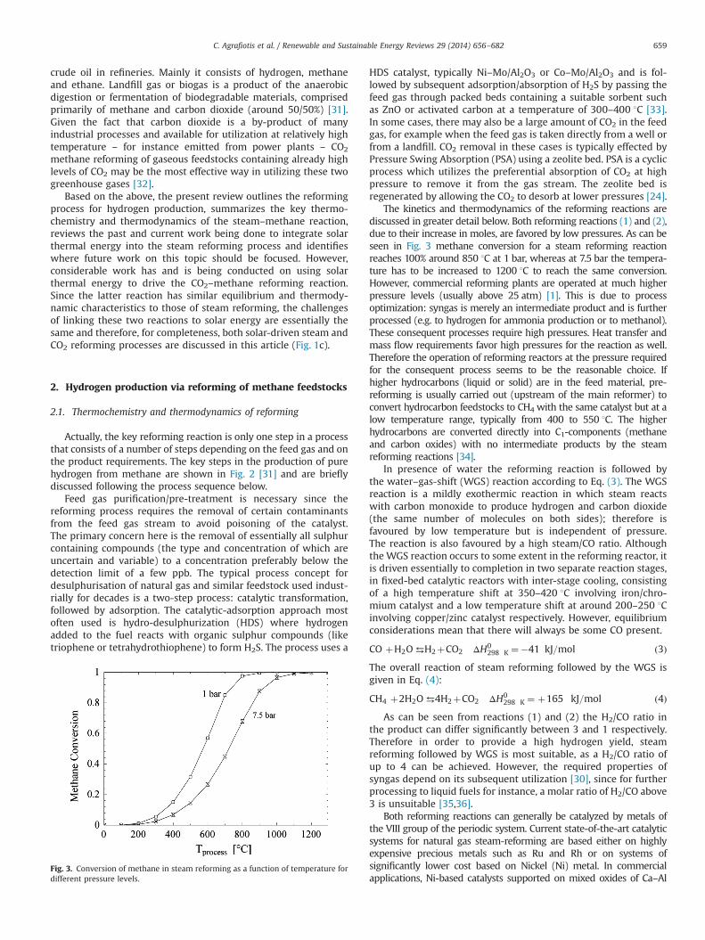
The kinetics and thermodynamics of the reforming reactions arediscussed in greater detail below. Both reforming reactions (1) and (2),due to their increase in moles, are favored by low pressures. As can beseen in Fig. 3 methane conversion for a steam reforming reactionreaches 100% around 850 1C at 1 bar, whereas at 7.5 bar the tempera-ture has to be increased to 1200 1C to reach the same conversion.However, commercial reforming plants are operated at much higherpressure levels (usually above 25 atm) [1]. This is due to processoptimization: syngas is merely an intermediate product and is furtherprocessed (e.g. to hydrogen for ammonia production or to methanol).These consequent processes require high pressures. Heat transfer andmass flow requirements favor high pressures for the reaction as well.Therefore the operation of reforming reactors at the pressure requiredfor the consequent process seems to be the reasonable choice. Ifhigher hydrocarbons (liquid or solid) are in the feed material, pre-reforming is usually carried out (upstream of the main reformer) toconvert hydrocarbon feedstocks to CH4 with the same catalyst but at alow temperature range, typically from 400 to 550 1C. The higherhydrocarbons are converted directly into C1-components (methaneand carbon oxides) with no intermediate products by the steamreforming reactions [34].
In presence of water the reforming reaction is followed bythe water–gas-shift (WGS) reaction according to Eq. (3). The WGSreaction is a mildly exothermic reaction in which steam reactswith carbon monoxide to produce hydrogen and carbon dioxide(the same number of molecules on both sides); therefore isfavoured by low temperature but is independent of pressure.The reaction is also favoured by a high steam/CO ratio. Althoughthe WGS reaction occurs to some extent in the reforming reactor, itis driven essentially to completion in two separate reaction stages,in fixed-bed catalytic reactors with inter-stage cooling, consistingof a high temperature shift at 350–420 1C involving iron/chro-mium catalyst and a low temperature shift at around 200–250 1Cinvolving copper/zinc catalyst respectively. However, equilibriumconsiderations mean that there will always be some CO present.
CO þH2O⇆H2þCO2 ΔH0298 K ¼�41 kJ=mol ð3Þ
The overall reaction of steam reforming followed by the WGS isgiven in Eq. (4):
CH4 þ2H2O ⇆4H2þCO2 ΔH0298 K ¼ þ165 kJ=mol ð4Þ
As can be seen from reactions (1) and (2) the H2/CO ratio inthe product can differ significantly between 3 and 1 respectively.Therefore in order to provide a high hydrogen yield, steamreforming followed by WGS is most suitable, as a H2/CO ratio ofup to 4 can be achieved. However, the required properties ofsyngas depend on its subsequent utilization [30], since for furtherprocessing to liquid fuels for instance, a molar ratio of H2/CO above3 is unsuitable [35,36].
Both reforming reactions can generally be catalyzed by metals ofthe VIII group of the periodic system. Current state-of-the-art catalyticsystems for natural gas steam-reforming are based either on highlyexpensive precious metals such as Ru and Rh or on systems ofsignificantly lower cost based on Nickel (Ni) metal. In commercialapplications, Ni-based catalysts supported on mixed oxides of Ca–Al
Fig. 3. Conversion of methane in steam reforming as a function of temperature fordifferent pressure levels.
C. Agrafiotis et al. / Renewable and Sustainable Energy Reviews 29 (2014) 656–682 659
[37] or Mg–Al [38] of the hexa-aluminates and spinels structures (e.g.CaAl6O10 or MgAl2O4 respectively) have proved to be most suitable,due to low cost and high catalytic activity. Other catalysts are notpreferred due to high costs (noble metals) or technical issues (Feand Co). The mixed oxide supports are traditionally synthesized by co-firing of the corresponding oxides at high temperatures (41600 1C)for extended periods or from wet chemistry routes that also involvesintering of precipitated powders (even though at lower tempera-tures). This firing is followed by a second calcination step at 500–700 1C under H2 flow to reduce NiO to “active” Ni.
The two main issues remaining in reformer design utilizingNi-based catalysts are sulphur compounds in the feed and carbonformation at the catalytically active site. While the first, asmentioned, can usually be eliminated by a hydrogenator followedby a ZnO bed, the latter constitutes a more complicate issue.Carbon formation in reforming reactions occurs mainly due tomethane decomposition (pyrolysis) or disproportionation of car-bon dioxide according to Eqs. (5) and (6), respectively.
CH4-C þ 2H2 ð5Þ
2CO -C þ CO2 ð6Þ
Both reactions (5) and (6) are catalyzed by metals; thereforethe risk of carbon formation is high in presence of Ni-basedcatalysts. As reported [4], at low temperatures, adsorbed hydro-carbons may accumulate on the nickel surface and slowly betransformed into a polymer film (“gum”) blocking the nickelsurface. At high temperatures, ethylene from the pyrolysis ofhigher hydrocarbons may lead to pyrolytic coke, which mayencapsulate the catalyst pellets. Whisker carbon formed due tothe dissociation of adsorbed hydrocarbons or carbon monoxideon the metal surface to give adsorbed carbon atoms which aredissolved in the metal particle, is the principal product of carbonformation in steam reforming. At a given temperature and pres-sure and for a given hydrocarbon feed, carbon will be formedbelow a critical steam-to-carbon ratio. This critical steam-to-carbon ratio increases with temperature. Thus in commercialsteam reforming plants most commonly the introduction of excesssteam into the feed is used for the reduction of carbon formationrisk. Usually the steam to carbon ratio S/C is set between 2 and 5(resulting in an atomic H/C ratio of 8 to 15). Therefore the share ofsensible heat in the process is largely increased and the chemicalefficiency of the process decreased. As can be seen from Eq. (2),considering that the aim of the process is a complete conversion ofmethane, the maximum H/C ratio in dry reforming is 2, decreasingwith over stoichiometric CO2 content in feed. Therefore in dryreforming processes noble metals are more commonly used ascatalysts, because reforming can be operated at significantly lowerH/C ratios without carbon formation. Another possibility for theinhibition of carbon formation is the addition of promoters to theNi based catalyst (e.g. alkaline earth metal oxides) [1,4,8,39–41].
After the shift reaction, the product gas (“raw synthesis gas”)consists mainly of H2 and CO2, and some impurities such asunconverted CH4 and CO. Therefore, the last “process box” inFig. 2 – purification – is dependent on the gas separationtechnology employed. Modern steam reforming plants typicallyuse PSA to remove the CO2 from the product hydrogen; thisprocess also removes any remaining CO and CH4 to produce99.99% pure hydrogen. Alternative separation technologies basedon solvents, such as amines, for CO2 absorption require a separatemethanation step to remove the CO from the product gas. Hereby “methanation” is meant the reverse of the steam reformingreaction where the undesired CO is converted to CH4 (reaction 7).Just like in the case of reforming though, there are two possible“methanation” reaction schemes referred in the literature,
producing in addition to CH4, H2O or CO2 respectively, as follows:
3H2þCO⇔CH4þH2O ðgÞ ð7Þ
2H2þ2CO⇔CH4þCO2 ðgÞ ð8Þ
2.2. Current industrial status
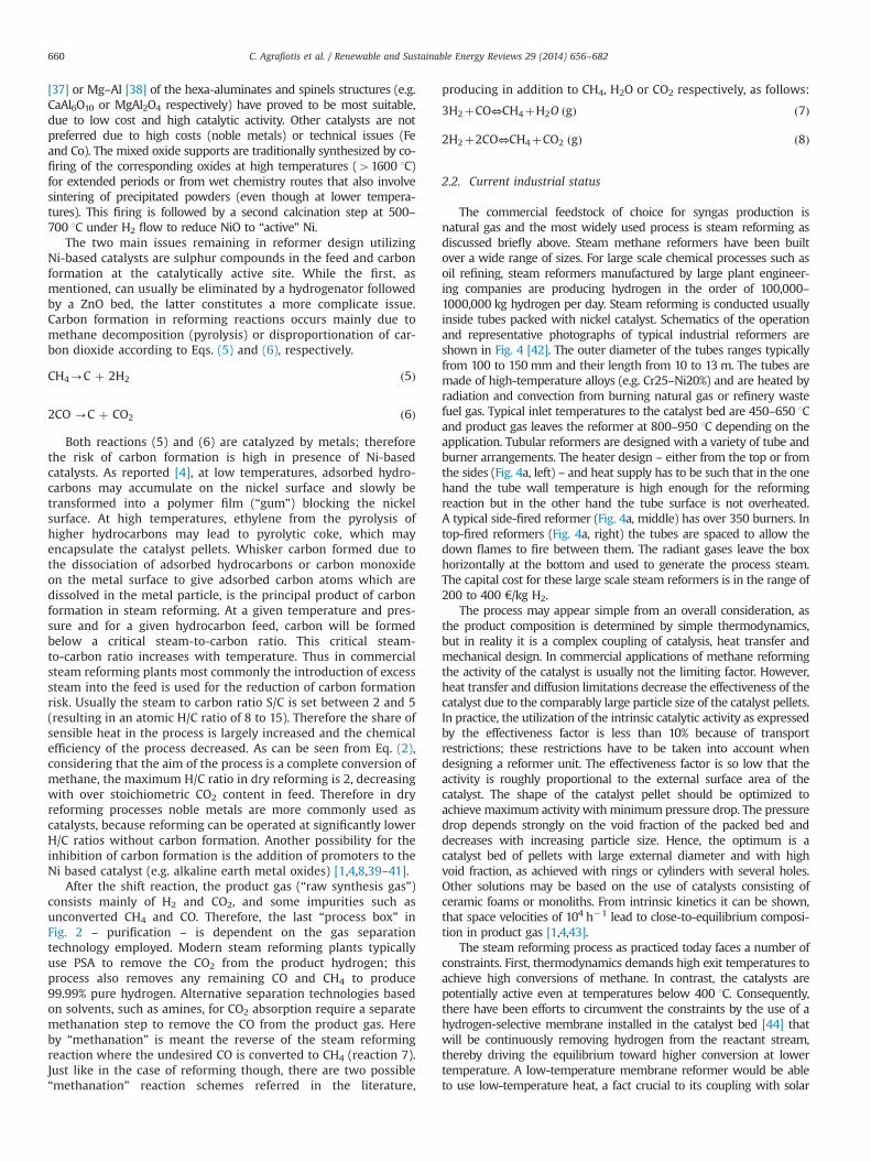
The commercial feedstock of choice for syngas production isnatural gas and the most widely used process is steam reforming asdiscussed briefly above. Steam methane reformers have been builtover a wide range of sizes. For large scale chemical processes such asoil refining, steam reformers manufactured by large plant engineer-ing companies are producing hydrogen in the order of 100,000–1000,000 kg hydrogen per day. Steam reforming is conducted usuallyinside tubes packed with nickel catalyst. Schematics of the operationand representative photographs of typical industrial reformers areshown in Fig. 4 [42]. The outer diameter of the tubes ranges typicallyfrom 100 to 150mm and their length from 10 to 13 m. The tubes aremade of high-temperature alloys (e.g. Cr25–Ni20%) and are heated byradiation and convection from burning natural gas or refinery wastefuel gas. Typical inlet temperatures to the catalyst bed are 450–650 1Cand product gas leaves the reformer at 800–950 1C depending on theapplication. Tubular reformers are designed with a variety of tube andburner arrangements. The heater design – either from the top or fromthe sides (Fig. 4a, left) – and heat supply has to be such that in the onehand the tube wall temperature is high enough for the reformingreaction but in the other hand the tube surface is not overheated.A typical side-fired reformer (Fig. 4a, middle) has over 350 burners. Intop-fired reformers (Fig. 4a, right) the tubes are spaced to allow thedown flames to fire between them. The radiant gases leave the boxhorizontally at the bottom and used to generate the process steam.The capital cost for these large scale steam reformers is in the range of200 to 400 €/kg H2.
The process may appear simple from an overall consideration, asthe product composition is determined by simple thermodynamics,but in reality it is a complex coupling of catalysis, heat transfer andmechanical design. In commercial applications of methane reformingthe activity of the catalyst is usually not the limiting factor. However,heat transfer and diffusion limitations decrease the effectiveness of thecatalyst due to the comparably large particle size of the catalyst pellets.In practice, the utilization of the intrinsic catalytic activity as expressedby the effectiveness factor is less than 10% because of transportrestrictions; these restrictions have to be taken into account whendesigning a reformer unit. The effectiveness factor is so low that theactivity is roughly proportional to the external surface area of thecatalyst. The shape of the catalyst pellet should be optimized toachieve maximum activity with minimum pressure drop. The pressuredrop depends strongly on the void fraction of the packed bed anddecreases with increasing particle size. Hence, the optimum is acatalyst bed of pellets with large external diameter and with highvoid fraction, as achieved with rings or cylinders with several holes.Other solutions may be based on the use of catalysts consisting ofceramic foams or monoliths. From intrinsic kinetics it can be shown,that space velocities of 104 h�1 lead to close-to-equilibrium composi-tion in product gas [1,4,43].
The steam reforming process as practiced today faces a number ofconstraints. First, thermodynamics demands high exit temperatures toachieve high conversions of methane. In contrast, the catalysts arepotentially active even at temperatures below 400 1C. Consequently,there have been efforts to circumvent the constraints by the use of ahydrogen-selective membrane installed in the catalyst bed [44] thatwill be continuously removing hydrogen from the reactant stream,thereby driving the equilibrium toward higher conversion at lowertemperature. A low-temperature membrane reformer would be ableto use low-temperature heat, a fact crucial to its coupling with solar
C. Agrafiotis et al. / Renewable and Sustainable Energy Reviews 29 (2014) 656–682660
plants as will be discussed below. Reactor simulations and experi-ments [45] have shown that the reformer exit temperature can indeedbe reduced to below 700 1C while the same conversion is maintained.However, the hydrogen produced according to this concept is at lowpressure and must be compressed to the usual delivery pressure of20 bar. This limitation renders the process uneconomical except whenvery low electricity prices prevail or when hydrogen is used as afeedstock for a fuel cell or as a low-pressure fuel.
In addition (and in contrast) to fired tubular reforming and heatexchange reforming shown in Fig. 4, where the heat is supplied byheat exchange from an external source, current industrial state-of-the-art reforming involves also the so-called adiabatic oxidativereforming concepts where the heat for the reforming reactions issupplied internally by combustion of part of the reactants. Theoverall reaction is adiabatic, meaning that there is no exchangeof heat with the surroundings (except a very limited heat loss).For production of synthesis gas the previously mentioned reac-tions (1) and (2) are not used; instead a sub-stoichiometricamount of oxygen is added which will thus be all consumedbecause this is the limiting reactant. It should be noted that thecombustion reactions are all irreversible. Two variants are
implemented known as partial oxidation (non-catalytic¼POX,catalytic¼CPO) and autothermal reforming (ATR), depending onthe required or desired syngas composition for the downstreamprocessing. In general ATR and POX lead to lower H2/CO ratios in thesyngas, compared to SR with consequent WGS. In POX the feedstockis oxidized partially by pure oxygen, as displayed in Eq. (9).
CH4þ12O2 ¼ COþ2H2 ΔH2981¼�38 kJ=mol ð9Þ
Autothermal reforming is really a hybrid of SR and POX,consisting of the reactions displayed in Eqs. (1), (3) and (9) aswell as (9a) [1,26,46]:
CH4þ32O2 ¼ COþ2H2O ΔH2981¼�520 kj=mol ð9aÞ
One major drawback of these two process variants is the largecost related to the air separation unit that can account for up to40% of the total cost of the syngas plant [4]. These variants are
Fig. 4. (a) Schematics of operation and (b) actual photographs of typical industrial reformers [42].
C. Agrafiotis et al. / Renewable and Sustainable Energy Reviews 29 (2014) 656–682 661
mainly attractive for large scale Fischer–Tropsch or Methanolsynthesis plants [26].
3. Solar-aided reforming
3.1. Solar concentration systems
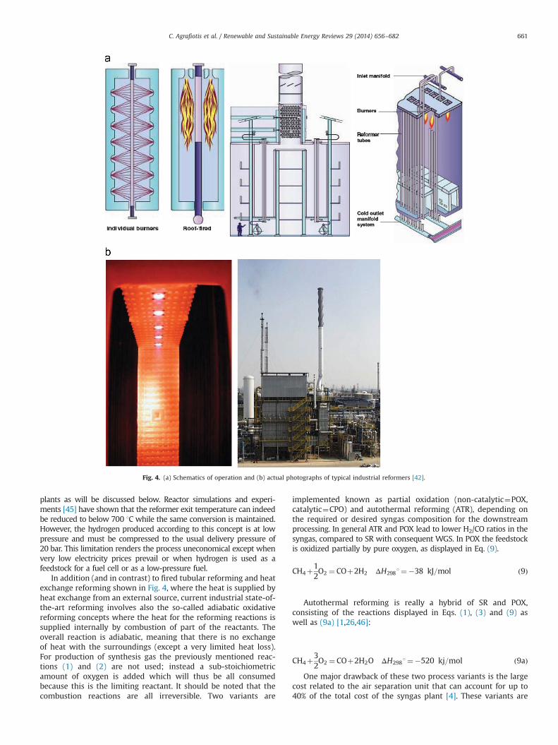
Large-scale concentration of solar energy is accomplished atpilot and commercial CSP plants with four kinds of optical config-uration systems using movable reflectors (mirrors) that track thesun, namely [47]: parabolic trough (PT) collectors, linear Fresnel (LF)reflector systems, dish–engine (DE) systems and power towers—also known as central receiver (CR) systems (Fig. 5). These systemshave been proven to be technically feasible in large-scale (MW)pilot and commercial solar thermal power plants (STPP) aimed atthe production of electricity from the sun′s rays: the solar energyis concentrated on a focal point by means of movable sun-trackingmirrors providing thus medium-to-high temperature heat. Thehigh-quality thermal energy obtained in this way needs to beconverted efficiently to mechanical work. For this purpose, a heatexchanger (receiver) is used, located in the concentration field ofthe radiation, in which a heat transfer fluid (air, water, saturated orsuperheated steam, thermal oil, or molten salt) is first solar-heatedand then transfers its enthalpy to the production of steam further
used in traditional energy cycles (Rankine, Brayton or Stirling) [48].The temperature that the heat transfer fluid can reach depends onthe operating principles of each CSP system and in particular to itscapability for solar concentration.
On the other hand concentrated solar power can be used toprovide high-temperature process heat as the necessary energysource for the performance of endothermic chemical reactions inthe so-called solar thermochemical processes. Solar thermoche-mical applications, although not as far developed as solar thermalelectricity generation, employ the same solar concentrating tech-nologies but instead of being targeted to power generation, theconcentrated solar radiation is focused on an integrated receiver/reactor where endothermic chemical reactions are performedtargeted to the production of useful chemicals.
Parabolic trough and Linear Fresnel technologies currentlyoperate at moderate solar concentration ratios with thermal oilor water–steam at working temperatures usually below 500 1C.Thus, regardless of the type of reforming reactor and catalyst, thehigher temperatures required for steam or CO2 methane reformingprocesses effectively limit the solar concentrator choice to the twotypes of high-solar-concentration ones namely, the parabolic dishcollector and the central tower receiver.
3.2. Coupling reforming with solar energy: Solar receiver–reactorconcepts
Both the steam reforming reaction (1) and the CO2 reformingreaction (2) are highly endothermic and therefore offer an oppor-tunity to embed and thus store solar energy. If solar energy is usedto provide the heats of reaction for reactions (1) and (2), in the onehand, a reduction of fossil fuel consumption is achieved becauseby this way fossil fuels are not used to generate high temperature,instead they are only used as a feedstock. On the other hand, theproduct gas will contain 26 and 31% of solar energy embodied inchemical form respectively (low heating value basis, assumingwater stays as a vapour). As already mentioned, in presence ofwater the reforming reaction is followed by the water–gas-shift(WGS) reaction according to Eq. (3). Because the WGS reaction isexothermic, the conversion of CO to hydrogen and CO2 actuallyreduces the amount of energy that can be stored in the products,to 21% in both cases (since in both cases 4 mol of H2 are producedper mole of methane) [24].
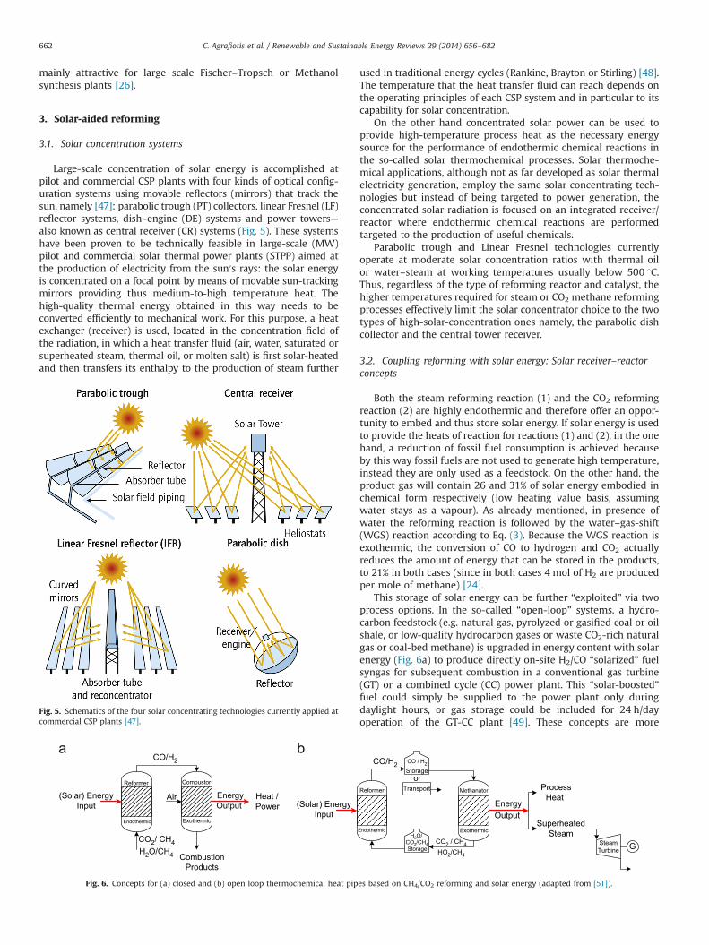
This storage of solar energy can be further “exploited” via twoprocess options. In the so-called “open-loop” systems, a hydro-carbon feedstock (e.g. natural gas, pyrolyzed or gasified coal or oilshale, or low-quality hydrocarbon gases or waste CO2-rich naturalgas or coal-bed methane) is upgraded in energy content with solarenergy (Fig. 6a) to produce directly on-site H2/CO “solarized” fuelsyngas for subsequent combustion in a conventional gas turbine(GT) or a combined cycle (CC) power plant. This “solar-boosted”fuel could simply be supplied to the power plant only duringdaylight hours, or gas storage could be included for 24 h/dayoperation of the GT-CC plant [49]. These concepts are more
Fig. 5. Schematics of the four solar concentrating technologies currently applied atcommercial CSP plants [47].
Fig. 6. Concepts for (a) closed and (b) open loop thermochemical heat pipes based on CH4/CO2 reforming and solar energy (adapted from [51]).
C. Agrafiotis et al. / Renewable and Sustainable Energy Reviews 29 (2014) 656–682662
thermally efficient than simply using the solar energy to producesteam because they harvest the solar energy in chemical form,rather than in sensible heat; thus the solar energy share in theproduct fuel can be converted to electricity at significantly higherefficiencies in large GTCC plants (at 45–50% thermal efficiency)rather than just using it in the less efficient steam turbine (ST)
cycle (at 30–35% thermal efficiency) [50,51]. Additional potentialutilization of the product syngas is directed to fuel cells (FC), forfurther processing to specialty chemicals and plastics and liquidfuels (methanol and gasoline).
In the so-called “closed-loop” systems, a high-quality hydrocar-bon feedstock such as methane (CH4) is converted to syngas via
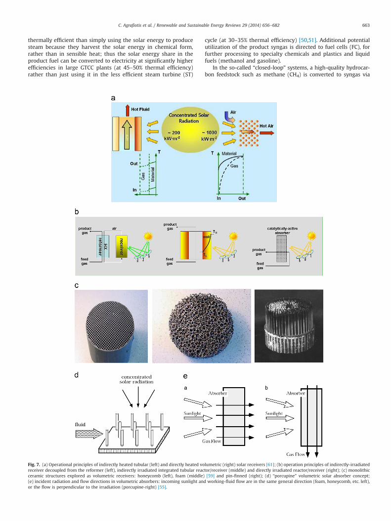
Fig. 7. (a) Operational principles of indirectly heated tubular (left) and directly heated volumetric (right) solar receivers [61]; (b) operation principles of indirectly-irradiatedreceiver decoupled from the reformer (left), indirectly irradiated integrated tubular reactor/receiver (middle) and directly irradiated reactor/receiver (right); (c) monolithicceramic structures explored as volumetric receivers: honeycomb (left), foam (middle) [59] and pin-finned (right); (d) “porcupine” volumetric solar absorber concept;(e) incident radiation and flow directions in volumetric absorbers: incoming sunlight and working-fluid flow are in the same general direction (foam, honeycomb, etc. left),or the flow is perpendicular to the irradiation (porcupine-right) [55].
C. Agrafiotis et al. / Renewable and Sustainable Energy Reviews 29 (2014) 656–682 663
solar reforming; the syngas is then stored or transported off-siteprior to conversion back to CH4 in a methanation reactor thatrecovers the solar energy as heat for industrial processes or powergeneration (Fig. 6b). Closed-loop solar reforming of CH4 and energyrecovery in a methanator has been considered as a method forstorage of solar energy that would match the short-term storagerequirements of steam-cycle power plants for peaking powergeneration or provide longer-term storage and/or thermal energytransport over moderate distances to multiple sites for process heatapplications (between, for example, high-insolation solar collectionsites and major industrial centers) [52]. Both methanation reactions(7) and (8) are exothermic and the energy recovered in themethanator can in principle either be integrated with a conven-tional steam turbine power plant or be used for the production ofhigh grade process heat. However, because of this reaction exother-micity and in order to obtain high methanation conversion,temperatures must be controlled not to exceed a medium range,otherwise the back reaction (reforming) can take place—a fact thatcan limit the usage of the steam produced only for process heatand not for power generation. Traditionally, this has been handledby using a high recycle and thus diluting the inlet gas in order
to keep the temperature below 450 1C. However, nowadays,there are a number of technology concepts and pilot plants around(e.g. TREMPTM process of Haldor Topsoe) to recover the heat ashigh-pressure superheated steam at 100 bar g/540 1C that can beincorporated directly in a steam turbine power cycle [53].
For the efficient design and operation of solar receiver/reactors,concepts from “traditional” chemical reactor engineering shouldbe combined with ways to achieve efficient heating of the reactorvia concentrated solar irradiation. Just like in the “traditional” non-solar chemical engineering, the catalytic reactor type can bedistinguished in two broad categories depending on whether thecatalyst particles are distributed randomly or are “arranged” inspace at the reactor level: the first category includes packed andfluidized catalytic beds; the second includes the so-called “struc-tured” catalytic systems like honeycomb, foam and membranecatalytic reactors, all three of them being free of randomness at thereactor′s level [54].
Solar receivers can be distinguished in two broad categoriesaccording to the mechanism of transferring the solar heat tothe heat transfer fluid: directly and indirectly heated ones. Thecommon characteristic of the historically precedent indirectly
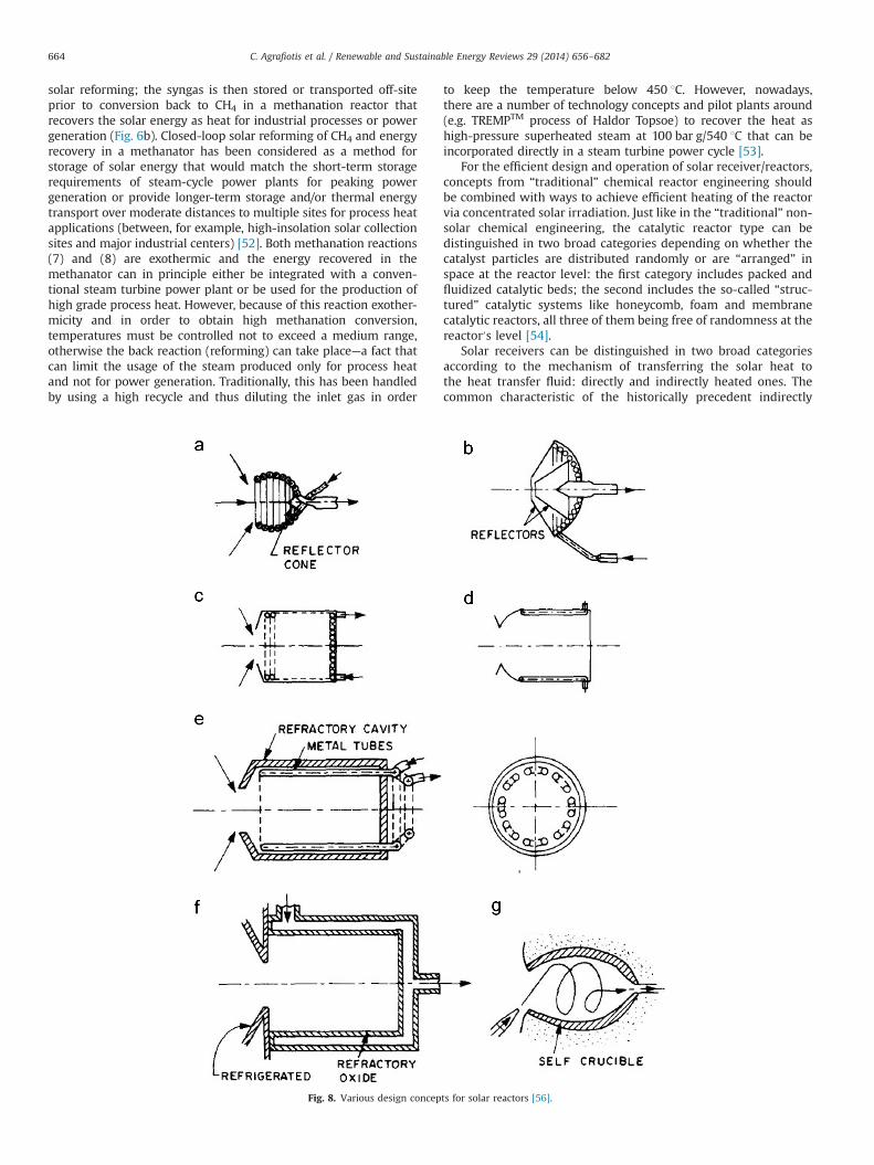
Fig. 8. Various design concepts for solar reactors [56].
C. Agrafiotis et al. / Renewable and Sustainable Energy Reviews 29 (2014) 656–682664
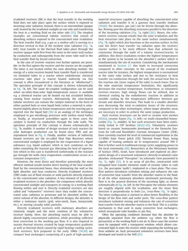
irradiated receivers (IIR) is that the heat transfer to the workingfluid does not take place upon the surface which is exposed toincoming solar radiation. Instead, there is an intermediate opaquewall, heated by the irradiated sunlight on one side and transferringthe heat to a working fluid on the other side [55]. The simplestexamples are conventional tubular receivers that consist ofabsorbing surfaces exposed to the concentrated solar irradiation.The heat transfer fluid (e.g. a gas or a molten salt) is moving in adirection vertical to that of the incident solar radiation (Fig. 7a,left); heat transfer to the thermal fluid takes place through thereceiver opaque walls first from the outer to the inner wall surfaceby conduction and subsequently from the inner tube wall to theheat transfer fluid by forced convection.
In the case of receiver–reactors two further options are possi-ble: in the first option the receiver and the reactor are de-coupled.The latter is not located within the solar absorbing module: theenergy of a solar-receiver-heated heat transfer fluid is transferredvia insulated tubes to a reactor where endothermic chemicalreactions take place (a reactor heated indirectly via thisconcept is often encountered in the literature as “allothermal”).The operation principle of this concept is shown schematicallyin Fig. 7b, left. The same de-coupled configuration can be usedwhen an-other-than-solar high-temperature source is availablee.g. a chemical reactor can be heated via hot circulated Heliumcoming from nuclear reactors. Alternatively, the solar-heatedtubular receivers can contain the catalyst material in the form ofeither packed beds or even liquid beds (when a material is solar-heated slightly above its fusion temperature and the reacting gas isinjected into the liquid bed [56] in an analogy of the techniqueemployed in gas metallurgy processes with molten metal baths)or, finally, as structured assemblies—again in these cases thecatalyst is heated via conduction through the tube walls. Theoperation principle of this concept is shown schematically inFig. 7b, middle. A number of design versions of such reactors forsolar hydrogen production can be found since 1981 and arereproduced here in Fig. 8. Finally, another version of indirectlyheated receivers are the so-called Heat Pipe Receivers whereconcentrated sunlight is employed for the evaporation of a liquidsubstance (e.g. liquid sodium) which in turn condenses on thetubes containing the reactant gas, liberating the heat of vaporiza-tion which in this case is transferred isothermally to the reactantgas through the walls since evaporation–condensation occurs at aconstant temperature [57].
However, the most direct and therefore potentially the mostefficient method would involve direct heating of the heat transferfluid by the concentrated beam, thus eliminating the wall as thelight absorber and heat conductor. Directly irradiated receivers(DIR) make use of fluid streams or solid particles directly exposedto the concentrated solar radiation. A key element of all directlyirradiated receivers is the absorber: the component which absorbsconcentrated sunlight and transports its energy to a working fluidflowing within and over it. Directly irradiated receivers are alsocalled and “volumetric” receivers since they enable the concen-trated solar radiation to penetrate and be absorbed within theentire volume of the absorber. In different designs, the absorber iseither a stationary matrix (grid, wire-mesh, foam, honeycomb,etc.), or moving (usually solid) particles.
Directly irradiated receivers with stationary absorbers arerelatively simple and the most common of the volumetricreceiver family. Here, the absorbing matrix must be able toabsorb highly concentrated radiation, while providing sufficientheat convection to the working gas flow. It is also required tosustain thermal stresses created by large temperature gradientsas well as thermal shock caused by rapid heating–cooling cycles.Such receivers, first proposed in the early 1980s [56,58] arecompact heat exchangers comprising of a pack of high-porosity
material structures capable of absorbing the concentrated solarradiation and transfer it to a gaseous heat transfer medium[59,60]. For instance, gas (air) can be driven through the absor-ber, flowing past the absorbing structures parallel to the directionof the incoming radiation (Fig. 7a, right) [61]. Hence, the volu-metric receiver concept entails that the solar irradiation and theheat extraction take place on the same surface simultaneously(Fig. 7b, right) which also functions as the reaction surface. In thiscase the direct heat transfer via radiation upon the receiver/reactor surface is far more efficient than that achieved viaconvection through the walls of a tubular receiver/reactor. Inaddition, this direct irradiation evokes the highest temperaturesin the system to be located on the absorber′s surface which issimultaneously the site of reaction. Considering the mechanismsmentioned in Section 2.1 this leads to increased conversioncompared to other concepts. In the concept of the irradiatedreactor tube for instance, the highest temperature is encounteredat the outer tube surface and due to the resistance to heattransfer via conduction through the wall, the actual heat flux tothe reaction site (inner region of the tube) is much lower. Due tothe tube materials temperature limitations, this significantlydecreases the reaction temperature. Furthermore, in volumetricreceiver–reactors, high energy fluxes can be utilized, due tochemical cooling by the endothermic reaction in addition tosensible cooling by the temperature difference between gasstream and absorber structure. This leads to a smaller absorberarea decreasing the total re-radiation losses of the structure,compared to the other technologies, where larger absorber areasare necessary in order to achieve the same syngas production.
Such receiver structures can be steel or ceramic wire meshes[60,62], ceramic foams (Fig. 7c, left)—or multi-channelled honey-combs (Fig. 7c, middle). In fact such structures have been exten-sively tested in CSP facilities [60,62–65]. Volumetric receiversbased on ceramic honeycombs developed in the Deutsche Zen-trum fur Luft-und Raumfahrt—German Aerospace Center (DLR),have currently reached the level of commercial exploitation in the1.5 MWe Solar Tower Julich (STJ) Thermal Power Plant, beingcapable of heating ambient air to temperatures around 700 1Cthat is further used in traditional energy cycles supplying power tothe local community [66]. Researchers at the Weizmann Instituteof Science (WIS), Israel, have introduced and explored an alter-native design of a structured volumetric (directly-irradiated) solarabsorber, nicknamed “Porcupine”, its schematic view presented inFig. 7c, right [55]. It is an array of pin-fins, constructed withelongated heat transfer elements made of ceramic tubes or rods(i.e., the porcupine ‘quills’), implanted in a base plate. The cross-flow pattern introduces turbulent mixing and enhances the rateof convective heat transfer from the absorber matrix to the fluid.In all the other stationary absorbers mentioned previously, theflow is in the general direction of the incoming light, as shownschematically in Fig. 4e, left. In the Porcupine the tubular elementsare roughly aligned with the irradiation, and the mean flowdirection is perpendicular to both (i.e., cross-flow; Fig. 7e right).The latter configuration is claimed to allow better flexibility in thedesign of the flow inlet and outlet ports. The cross-flow patternintroduces turbulent mixing and enhances the rate of convectiveheat transfer from the absorber matrix to the fluid. This is a similarmechanism to that used in many convective heat exchangers,which incorporate tube bundles or pin fins.
Often the operating conditions demand that the absorber bephysically separated from the ambient; e.g. when the flow ispressurized, or the working fluid is not air. In these cases the receivermust be equipped with a transparent window, which allows con-centrated light to enter the receiver while separating the working gasfrom ambient air. Such pressurized volumetric receivers have beendeveloped and tested in the WIS [67].
C. Agrafiotis et al. / Renewable and Sustainable Energy Reviews 29 (2014) 656–682 665
In a direct analogy with “conventional” catalytic applications[68,69] it becomes obvious that all three structured porous volu-metric solar absorber modules shown in Fig. 7c can be coated withproper functional materials capable to perform/catalyse a variety ofhigh-temperature chemical reactions – among them reforming –
and thus be “transformed” and adapted to operate as solar chemicalreceiver/reactors where chemical reactions can take place in anefficient and elegant manner with the aid of the functionalmaterials immobilized upon their porous walls [48]. Such devicescomprise an integrated solar receiver – chemical reactor module,in which a catalyst-coated porous matrix volumetrically absorbsconcentrated solar (radiant) energy directly at the catalyst sites,promoting heterogeneous reactions with gases flowing through thematrix (absorber) – thus they are frequently referred as directlyirradiated volumetric receiver–reactors (acronym DIVRR). In thisway absorbed radiation is converted from thermal to chemical form,thus storing solar energy in the chemical bonds of the reactionproducts rather than as thermal energy in a working fluid. On the
other hand, direct heating in the case of receiver/reactors necessi-tates the use of a transparent window isolating the reactant gasstreams from the ambient air and providing for reactor operationunder non-atmospheric pressures if needed.
Each receiver/reactor type has its advantages and drawbacks;it is not therefore surprising that essentially all receiver/reactorconcepts above have been used for solar-driven reforming to ahigher or lower extent, having reached different scale-up levels. Infact, natural gas reforming has been the first process for solarconversion of hydrocarbons tested at an engineering scale of somehundreds of kilowatts of solar power input.
Additional issues have to do with the inherently transientnature of solar operation, requiring specific measures to preventmalfunctioning of the process and to avoid non-preferable processconditions. For instance, with respect to the carbon depositionissue mentioned above, during solar operation the dangerousregion of temperatures where carbon deposition is likely to takeplace, is crossed at least twice a day upon morning start-up and
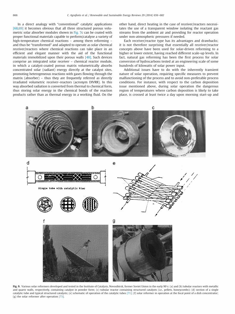
Fig. 9. Various solar reformers developed and tested in the Institute of Catalysis, Novosibirsk, former Soviet Union in the early 90′s: (a) and (b) tubular reactors with metallicand quartz walls, respectively, containing catalyst in powder form; (c) tubular reactor containing structured catalysts (i.e., pellets, honeycombs); (d) section of a singlecatalytic tube and typical structured catalysts; (e) schematic of operation of the catalytic tubes [71]; (f) solar reformer in operation at the focal point of a dish concentrator;(g) the solar reformer after operation [73].
C. Agrafiotis et al. / Renewable and Sustainable Energy Reviews 29 (2014) 656–682666
daily shutdown. Therefore very specific and careful operationalmeans has to be taken. The adjustment of mass flows and inparticular the S/C ratio of the reactant gas will be an importantparameter to control the process. A suitable process strategy canforesee for instance a switch-on of reactants′ flow after havingreached a sufficient reaction temperature in the mornings and aswitch off just after the Direct Normal Irradiance (DNI) has fallenbelow a certain threshold in the evenings.
3.3. Worldwide research in solar thermal reforming of gaseousfeedstocks
3.3.1. Solar thermal reforming of methaneThe concept of solar-driven reforming was first coined in 1982 by
J. A. Chubb of the U.S. Naval Research Laboratory U.S.A., who proposedthe CO2/CH4 reforming-methanation cycle as a mechanism for con-verting and transporting solar energy via solar receivers [52] andoperated a solar tubular reformer with a Ruthenium (Ru) catalyst atthe White Sands Solar Furnace [70]. Interest on this technology wasrevived at the late 1980s with the initial research in solar-drivenreforming focusing on the concept of a closed loop for storage andtransport of solar energy, in analogy to that with high temperatureenergy being supplied by a nuclear reactor. Parallel work took placeduring the same period at the Institute of Catalysis, Novosibirsk in theformer Soviet Union [71–73] where Soviet researches designed andtested a variety of catalytic reforming reactors/receivers on the sameresearch line of the CO2/CH4 reforming-methanation cycle mentionedabove. Representative photographs of such tubular solar reformerscontaining either powder or structured catalysts tested during thattime are shown in Fig. 9 [71]. In particular, solar steam reforming in aclosed cycle has been demonstrated using a Ru reforming catalyst anda nickel methanation catalyst [73]. The solar catalytic reformer waspositioned in the focal point of a parabolic dish (Fig. 9c). The reformerassembly contained in the insulated housing a water evaporator, asuperheater of steam, a solar-flux receiving cavity around which thecatalyst bed was located, and counter-current heat exchangers forrecuperation of the heat of reaction products. Water evaporationand heating of steam to the temperature of the catalyst bed wereaccomplished solely at the expense of solar energy. The diameter ofthe reformer′s external housing was 42 cm, its height 34 cm and theweight of all reactors including the catalyst did not exceed 15 kg. The
reaction was carried out at levels of total power input of incident solarenergy ca 5 kW and pressures between 1.8 and 2.8 atm, where almostcomplete methane reforming was reported at gas temperatures at thecatalyst bed outlet between 650 and 700 1C.
At the same time, the development of solar-based CO2/CH4
reforming technology was studied at the technical-scale in Israeland Germany as part of the International Energy Agency SolarPower and Chemical Energy Systems (SolarPACES) R&D program.Between 1988 and 1992, in an attempt to develop more econom-ical, compact receivers for methane reforming, experiments on alaboratory scale were started at Sandia National Laboratories(SNL), U.S.A. [74], at DLR and at the WIS, both with indirectlyheated tubular reactors as well as with the first windowedreceiver–reactors where the catalyst was heated directly by aconcentrated solar beam [75–77]. The technical characteristicsand results of all these studies above were comparatively sum-marized [78].
A significant amount of work has been conducted over the last25 years on the development and scale-up of the technology ofsolar reforming of methane and other hydrocarbons at DLR, WIS,and SNL, in several cases within joint Projects. Relevant researchon solar reforming concepts is performed currently all over theworld, principally by laboratories and research institutes thatpossess pilot-to-large scale CSP facilities such as the PlataformaSolar de Almeria, Spain operated by Centro De InvestigacionesEnergéticas, Medioambientales Y Tecnológicas (PSA-CIEMAT), theEidgenoessische Technische Hochschule—Paul Scherrer Institute(ETH/PSI) in Zurich, Switzerland, the Ente per le Nuove tecnologie,l′ Energia e l′ Ambiente (ENEA) in Rome, Italy, in Europe, as well asby Department of Energy′s National Renewable Energy Laboratory(NREL), Sandia Corporation and the University of Colorado in U.S.A., the Commonwealth Scientific and Industrial Research Organi-zation (CSIRO) in Newcastle, Australia, the Niigata University andthe Tokyo Institute of Technology, in Japan and the Inha Universityin Korea, among others. The research activities can be divided intogeneral reformer concepts and concepts for the improvement ofthe catalyst system (i.e., catalyst and structure that it is appliedonto). Regarding the catalysts in solar reforming there are twomajor topics that require further development: the price for noblemetal catalysts that are suitable for dry reforming of methane istoo high for industrial application. Therefore, a Ni-based catalystcapable of performing dry reforming of methane without
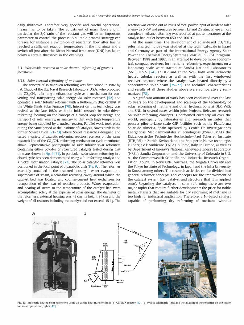
Fig. 10. Indirectly heated solar reformers using air as the heat transfer fluid: (a) ASTERIX reactor [82], (b) WIS′s; schematic (left) and installation of the reformer on the towerfor solar operation (right) [42].
C. Agrafiotis et al. / Renewable and Sustainable Energy Reviews 29 (2014) 656–682 667
deactivation due to carbon deposition has to be developed [79].The other obstacle exists in directly irradiated receiver/reactors.The catalytically activated absorber has to fulfill not only require-ments regarding the chemical reaction but also the requirementsregarding a solar absorber (i.e., high thermal shock resistance, lowreflectivity and emissivity).
It is worth noting in passing that a considerable amount ofwork has also been conducted on methane cracking, or thermaldecomposition to produce hydrogen and elemental carbon. Thiswork will not be discussed in detail, although it should berecognized that the high temperatures required for this process(in excess of 1500 1C) make this technology less suitable forconcentrated solar applications which appear best suited toprocesses below 1200 1C. It is further noted that due to thissubstantial energy penalty of the product hydrogen characterizingmethane cracking in contrast to reforming, the economics ofmethane cracking are strongly dependent on achieving a reason-able price for the carbon by-product rendering the added value ofthe produced carbon black a key point. The selling price dependson the product′s nano-structure and applications in the fields ofpolymer composites and batteries are targeted [80]. Because of theunstable reaction conditions it is not proven yet that such amarketable carbon by-product will be available.
A detailed description of the various research efforts worldwideis presented below, grouped on the basis of the solar heatingconcept employed (indirect or direct) and sub-divided on the basisof the heat transfer medium employed in each case. In thiscontext, the term “heat transfer medium” is used to define themedium that transfers the solar heat to the reactant gases(methane, steam, carbon dioxide). This classification has beenadopted in order to delineate the technical characteristics of eachapproach rather than the chronological evolution of the
technologies tested. The latter can be often confusing and circularsince it depends from local factors; many technologies are testedin parallel all over the world, new concepts are first tested underlab- or simulated solar irradiation conditions whereas other, moremature concepts become implemented faster at pilot-scale solarplants through large bi- or multi-lateral research projects invol-ving partners possessing large-scale solar facilities [81].
3.3.1.1. Indirectly heated reactors
Heat transfer medium: AirThis concept was first tested within the Advanced SteamReforming of Methane in Heat Exchange (ASTERIX) project, ajoint Spanish-German project carried out by CIEMAT and DLRin the late 1980s and early 1990s [82]. Within this experiment,the solar-driven Gas-Cooled Solar Tower (GAST) system at thePlataforma Solar de Almeria, Spain, was used to produce hot air(up to 0.36 kg/s at 1000 1C and 9 bar) to drive a separate steamreformer. This air is then fed back into the GAST cycle. In thiscase steam reforming of methane was performed in a 170 kW,tubular, 6-m long, packed catalyst bed reformer (Fig. 10a).A ceramic tubular receiver mounted on the central tower receiverat PSAwas employed to generate this hot air. Both natural gas anddemineralized water reactants were provided to the reformingpacked catalyst bed unit pre-heated in preheaters coaxiallyinstalled in the reforming reactor and in a superheater to about500 1C. Typically during the tests, solar-heated air was supplied tothe reformer at 980 1C and exiting the reformer at approximately420 1C, whereas the process gas mixture was heated through thecatalyst bed from 500 to about 850 1C at the bed end. Final CH4
conversions reported for air mass flows of 525 kg/h and water
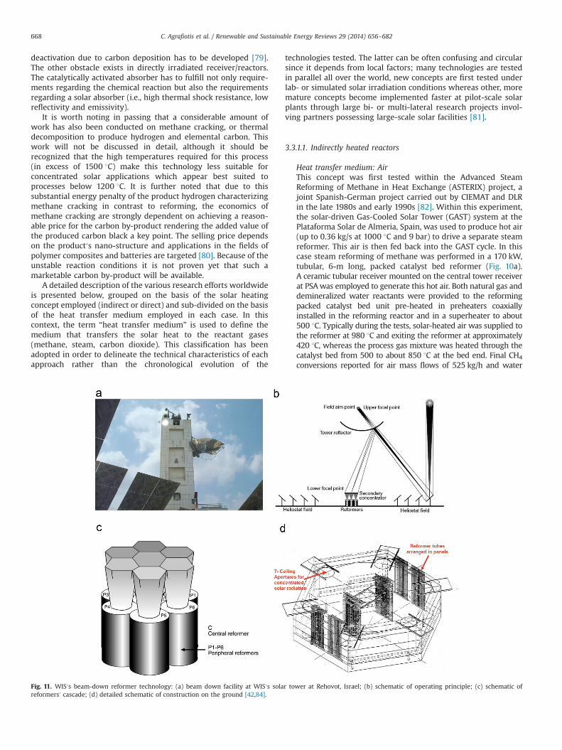
Fig. 11. WIS′s beam-down reformer technology: (a) beam down facility at WIS′s solar tower at Rehovot, Israel; (b) schematic of operating principle; (c) schematic ofreformers′ cascade; (d) detailed schematic of construction on the ground [42,84].
C. Agrafiotis et al. / Renewable and Sustainable Energy Reviews 29 (2014) 656–682668
mass flows from 26 to 39 kg/h were between 68 and 93%depending on the reformer′s temperature that varied from 702to 803 1C. The project demonstrated the technical feasibility ofproducing an industrial-quality synthesis gas under both steadystate and transient solar conditions.Solar reforming of methane by CO2 in tubular reactors has alsobeen studied at the WIS over the last two decades either as anopen loop process for the production of syngas for power
generation or as part of a closed loop reforming-methanationthermochemical heat pipe. Between 1993 and 1998 the WISoperated a solar central receiver for development of high-temperature technology, including the storage and transport ofsolar energy via CH4 reforming [74]. TheWIS facility was designedfor testing reformers up to about 480 kW absorbed energy, foreither steam or CO2 reforming, operating between 1 and 18 bar.After laboratory-scale studies of the reactions in a solar furnace at
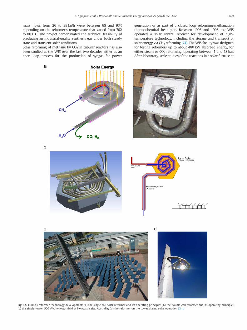
Fig. 12. CSIRO′s reformer technology development: (a) the single coil solar reformer and its operating principle; (b) the double-coil reformer and its operating principle;(c) the single-tower, 500 kW, heliostat field at Newcastle site, Australia; (d) the reformer on the tower during solar operation [24].
C. Agrafiotis et al. / Renewable and Sustainable Energy Reviews 29 (2014) 656–682 669
the 5–10 kW scale, a 480 kW tubular reformer was constructedand tested under real solar conditions at the WIS central towerreceiver. In contrast to the ASTERIX concept, in this case thereformer tubes were exposed to concentrated solar irradiation: acavity receiver containing eight vertical 2.5-inch-diameter and4.5-m-long reformer tubes was built, designed to produce syngasat 800 1C (Fig. 10b) [83].However, because of its greater volume and weight, placing atubular reformer on top of a solar tower was considered to be amajor limiting factor to the large scale development of the tubularreformer concept. To address scalability issues WIS researcherstransferred the concept to the so-called “beam down” receiver(Fig. 11 [84]); with the aid of an optical feature in the form of a75 m2 reflector shaped as a hyperboloid section attached to thetower at about 45 m above ground level (Fig. 11a), about onemegawatt of concentrated sunlight can be reflected down onto aground target. This optics allows a multi-megawatt tubularreformer to be built on the ground in a way resembling theconstruction of a conventional, commercial reformer with roofburners (Fig. 4a). The conceptual design of the ground tubularsolar reformer comprised seven units—one central unit and sixadjacent peripheral units, of a circular cross section with thetubular reactors having the proper geometrical dimensions incompliance with the power entering each reformer. Through anexample, the performance of a complete, 50 MWth, solar reform-ing system, including the entire optical path (heliostat field, towerreflector and secondary concentrators), heat transfer and kineticsof the reactions inside the reformer tubes has been modelled.However such a reformer has not been built and tested.In Australia, the solar reforming of methane is particularlyattractive in view of the country′s enormous areas of favourableinsolation and its very large reserves of natural gas and coal bedmethane that are co-located in many regions. Work in Australiaon solar methane reforming has been conducted by CSIRO sincethe early 1990s aimed at catalyst and reactor development forconducting the CO2-reforming reaction for application on bothopen- and closed-loop solar thermochemical heat pipes. CSIRObegan work on solar reforming in 1999, with its 25 kW singlecoil reformer (SCORE); a schematic of its operating principle isshown in Fig. 12a. The catalyst is packed in-between the innerand outer tubes; the inner tube is purely for counter-currentheating of the feed water stream. Production of solar-enrichedfuels and hydrogen via steam reforming of natural gas (25 kWLHV) at temperatures and pressures up to 850 1C and 20 bar wasdemonstrated on this single-coiled reformer coupled to a 107 m2
dish concentrator between 1998 and 2001. For the demonstra-tion facility (2002), the reformer was designed for up to 1000 hof operation using a high temperature stainless steel whereascommercial nickel-based steam reforming catalyst was used tocatalyse the reforming reactions.Between 1998 and 2001 CSIRO successfully completed a $7.5million project to demonstrate a solar thermal-fossil energyhybrid concept for solar-enriched fuels and electricity includingsolar steam reforming of natural gas to generate synthesis gassuitable for use as a fuel, further conversion of this gas to H2 andCO2 followed by recovery of CO2 in a concentrated form andfurther purification of the gas by methanation to produce fuelcell-grade hydrogen (o10 ppm of CO). In 2004, CSIRO built asingle-tower heliostat field of 500 kW capacity at its Newcastlesite of National Solar Energy Centre (Fig. 12c) with the objectiveof demonstrating this solar reforming process on a larger scale.The reason for changing to a tower was the improved economicsof the solar concentrator afforded by economies of scale. Solarresource at this site typically provided a direct normal incidentradiation peak of 800�900W/m2. In 2006 CSIRO demonstratedthe solar steam reforming process operating on this solar
tower over a commercial catalyst at reaction temperatures of700�800 1C and pressures of 5�10 bar. Subsequently, CSIROdesigned and installed in June 2009 a much larger, hexagonal-shape, dual-coil reformer (DCORE) capable of processing 200 kWthermal (LHV) natural gas at 10 bar and 850 1C (Fig. 12b and d).The length across the flats of the hexagonal shape coil is about2 m making the outer receiver dimensions of about 2.5 m. Stablecontrolled reactor temperatures and consistent Hydrogen pro-duction were reported [85,86]. CSIRO has taken a differentapproach to most overseas investigators by focusing on devel-oping and demonstrating solar-driven reformers that canachieve high methane conversions at lower temperatures(550–700 1C) ) [87]. This has a number of significant advantages,including a reduction in heat losses due to radiation andconvection so that the overall utilization of solar energy ismaximized. In this respect CSIRO developed its own catalystsand claimed higher activity at lower operating temperatures – aslow as 700 1C – compared to commercial reforming catalysts inthree different reforming operation modes (low steam, mixedand CO2 reforming).
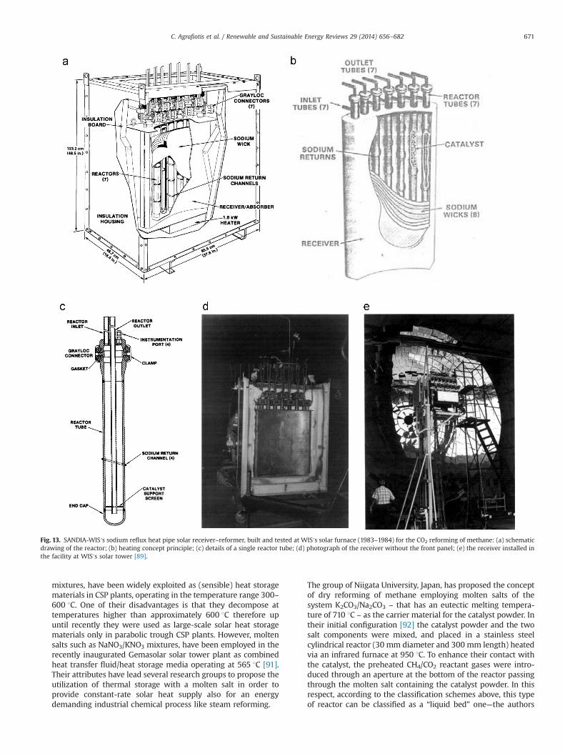
Heat transfer medium: Sodium (Na) vaporsIn this concept, liquid sodium contained in an evacuatedchamber evaporates under the effect of concentrated sunlightimpinging on one surface of the containment. The sodium vaporcondenses on the reactor tubes in the chamber and liberates theheat of vaporization. Passive techniques (channels, wicks, grav-ity, etc.) return the liquid sodium to the absorber. Advantagesclaimed are the excellent heat transfer characteristics of evapor-ating and condensing sodium that result in uniform tempera-tures throughout the chamber ensuring therefore isothermaloperation of the reactor tubes, with the rate of sodium con-densation determined by the local energy requirements of thereaction. The proof-of-concept of such a reactor was firstdemonstrated for steam reforming under simulated solar con-ditions using infrared lamp heating ([57,88]) and subsequentlyunder “real” solar irradiation within a SNL—WIS joint researchproject where a 20 kW sodium reflux solar reformer was builtand tested at WIS′s solar furnace (1983–1984) for the CO2
reforming of methane [89]. This receiver/reactor was a heat pipewith seven 2.5 m long tubes inside an evacuated metal boxcontaining sodium. A schematic of the operation concept andactual reactor photographs are shown in Fig. 13. The catalyst was0.5 wt% Rh supported on γ-alumina pellets 3.2 mm in diameter,filling two of the tubes in a packed bed configuration. The frontsurface of the box served as the solar absorber, consisting of a3.2 mm Inconel plate, curved in one dimension to produce amore uniform solar flux distribution and to provide structuralrigidity. In operation (Fig. 13e), concentrated sunlight heated thefront plate and vaporized sodium from awire mesh wick attachedto the other side. In these experiments, the wall temperature ofthe reactors (taken as the temperature of the sodium vapor) wasbetween 685 and 825 1C and the inlet flow rate (CH4þCO2)between 4400 and 6800 standard liters per hour (SLPH) underpressures 2–6 atm. The reactor′s temperature varied between 650and 800 1C. Methane conversions between 50 and 70% werereported with an energy input between 1.5 and 7.8 kW. Theexperimental campaign was terminated prematurely due to anoperational failure in the sodium evaporator, a fact that incombination with the flammability of Na vapors critically con-sidered in the solar community caused the abandonment of thisconcept for some time. However, recently, sodium – and moltenmetal′s in general – as heat transfer fluids get back into the focusof a number of research groups with new results published [90].
Heat transfer medium: Molten saltsMolten salts, in particular some molten nitrates and carbonates
C. Agrafiotis et al. / Renewable and Sustainable Energy Reviews 29 (2014) 656–682670
mixtures, have been widely exploited as (sensible) heat storagematerials in CSP plants, operating in the temperature range 300–600 1C. One of their disadvantages is that they decompose attemperatures higher than approximately 600 1C therefore upuntil recently they were used as large-scale solar heat storagematerials only in parabolic trough CSP plants. However, moltensalts such as NaNO3/KNO3 mixtures, have been employed in therecently inaugurated Gemasolar solar tower plant as combinedheat transfer fluid/heat storage media operating at 565 1C [91].Their attributes have lead several research groups to propose theutilization of thermal storage with a molten salt in order toprovide constant-rate solar heat supply also for an energydemanding industrial chemical process like steam reforming.
The group of Niigata University, Japan, has proposed the conceptof dry reforming of methane employing molten salts of thesystem K2CO3/Na2CO3 – that has an eutectic melting tempera-ture of 710 1C – as the carrier material for the catalyst powder. Intheir initial configuration [92] the catalyst powder and the twosalt components were mixed, and placed in a stainless steelcylindrical reactor (30 mm diameter and 300 mm length) heatedvia an infrared furnace at 950 1C. To enhance their contact withthe catalyst, the preheated CH4/CO2 reactant gases were intro-duced through an aperture at the bottom of the reactor passingthrough the molten salt containing the catalyst powder. In thisrespect, according to the classification schemes above, this typeof reactor can be classified as a “liquid bed” one—the authors
Fig. 13. SANDIA-WIS′s sodium reflux heat pipe solar receiver–reformer, built and tested at WIS′s solar furnace (1983–1984) for the CO2 reforming of methane: (a) schematicdrawing of the reactor; (b) heating concept principle; (c) details of a single reactor tube; (d) photograph of the receiver without the front panel; (e) the receiver installed inthe facility at WIS′s solar tower [89].
C. Agrafiotis et al. / Renewable and Sustainable Energy Reviews 29 (2014) 656–682 671
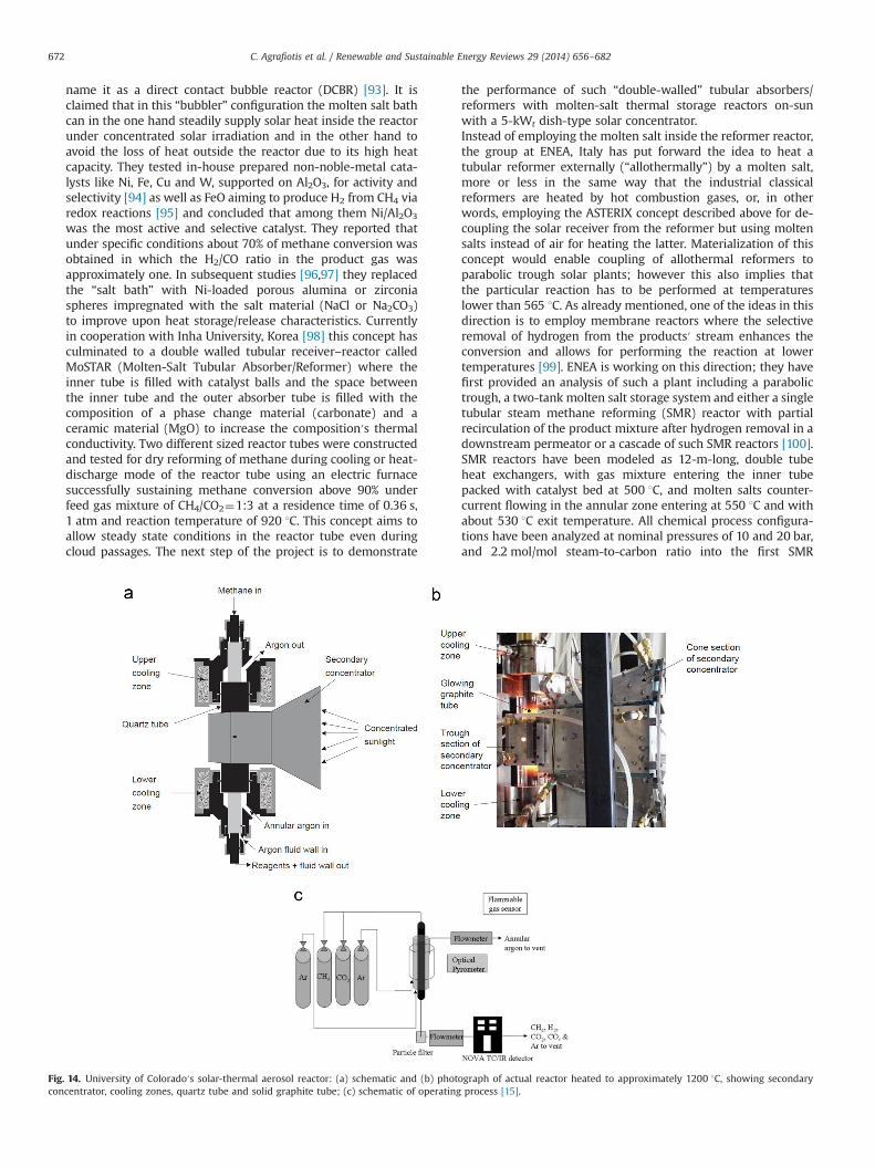
name it as a direct contact bubble reactor (DCBR) [93]. It isclaimed that in this “bubbler” configuration the molten salt bathcan in the one hand steadily supply solar heat inside the reactorunder concentrated solar irradiation and in the other hand toavoid the loss of heat outside the reactor due to its high heatcapacity. They tested in-house prepared non-noble-metal cata-lysts like Ni, Fe, Cu and W, supported on Al2O3, for activity andselectivity [94] as well as FeO aiming to produce H2 from CH4 viaredox reactions [95] and concluded that among them Ni/Al2O3
was the most active and selective catalyst. They reported thatunder specific conditions about 70% of methane conversion wasobtained in which the H2/CO ratio in the product gas wasapproximately one. In subsequent studies [96,97] they replacedthe “salt bath” with Ni-loaded porous alumina or zirconiaspheres impregnated with the salt material (NaCl or Na2CO3)to improve upon heat storage/release characteristics. Currentlyin cooperation with Inha University, Korea [98] this concept hasculminated to a double walled tubular receiver–reactor calledMoSTAR (Molten-Salt Tubular Absorber/Reformer) where theinner tube is filled with catalyst balls and the space betweenthe inner tube and the outer absorber tube is filled with thecomposition of a phase change material (carbonate) and aceramic material (MgO) to increase the composition′s thermalconductivity. Two different sized reactor tubes were constructedand tested for dry reforming of methane during cooling or heat-discharge mode of the reactor tube using an electric furnacesuccessfully sustaining methane conversion above 90% underfeed gas mixture of CH4/CO2¼1:3 at a residence time of 0.36 s,1 atm and reaction temperature of 920 1C. This concept aims toallow steady state conditions in the reactor tube even duringcloud passages. The next step of the project is to demonstrate
the performance of such “double-walled” tubular absorbers/reformers with molten-salt thermal storage reactors on-sunwith a 5-kWt dish-type solar concentrator.Instead of employing the molten salt inside the reformer reactor,the group at ENEA, Italy has put forward the idea to heat atubular reformer externally (“allothermally”) by a molten salt,more or less in the same way that the industrial classicalreformers are heated by hot combustion gases, or, in otherwords, employing the ASTERIX concept described above for de-coupling the solar receiver from the reformer but using moltensalts instead of air for heating the latter. Materialization of thisconcept would enable coupling of allothermal reformers toparabolic trough solar plants; however this also implies thatthe particular reaction has to be performed at temperatureslower than 565 1C. As already mentioned, one of the ideas in thisdirection is to employ membrane reactors where the selectiveremoval of hydrogen from the products′ stream enhances theconversion and allows for performing the reaction at lowertemperatures [99]. ENEA is working on this direction; they havefirst provided an analysis of such a plant including a parabolictrough, a two-tank molten salt storage system and either a singletubular steam methane reforming (SMR) reactor with partialrecirculation of the product mixture after hydrogen removal in adownstream permeator or a cascade of such SMR reactors [100].SMR reactors have been modeled as 12-m-long, double tubeheat exchangers, with gas mixture entering the inner tubepacked with catalyst bed at 500 1C, and molten salts counter-current flowing in the annular zone entering at 550 1C and withabout 530 1C exit temperature. All chemical process configura-tions have been analyzed at nominal pressures of 10 and 20 bar,and 2.2 mol/mol steam-to-carbon ratio into the first SMR
Fig. 14. University of Colorado′s solar-thermal aerosol reactor: (a) schematic and (b) photograph of actual reactor heated to approximately 1200 1C, showing secondaryconcentrator, cooling zones, quartz tube and solid graphite tube; (c) schematic of operating process [15].
C. Agrafiotis et al. / Renewable and Sustainable Energy Reviews 29 (2014) 656–682672
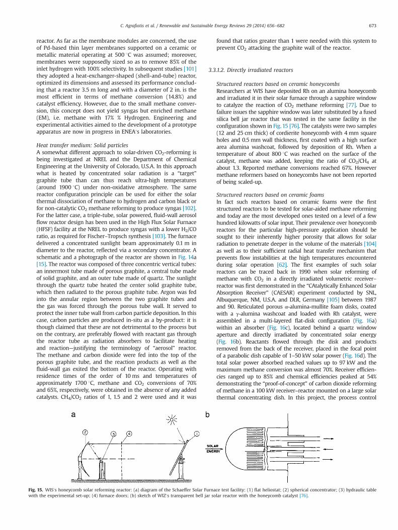
reactor. As far as the membrane modules are concerned, the useof Pd-based thin layer membranes supported on a ceramic ormetallic material operating at 500 1C was assumed; moreover,membranes were supposedly sized so as to remove 85% of theinlet hydrogen with 100% selectivity. In subsequent studies [101]they adopted a heat-exchanger-shaped (shell-and-tube) reactor,optimized its dimensions and assessed its performance conclud-ing that a reactor 3.5 m long and with a diameter of 2 in. is themost efficient in terms of methane conversion (14.8%) andcatalyst efficiency. However, due to the small methane conver-sion, this concept does not yield syngas but enriched methane(EM), i.e. methane with 17% % Hydrogen. Engineering andexperimental activities aimed to the development of a prototypeapparatus are now in progress in ENEA′s laboratories.
Heat transfer medium: Solid particlesA somewhat different approach to solar-driven CO2-reforming isbeing investigated at NREL and the Department of ChemicalEngineering at the University of Colorado, U.S.A. In this approachwhat is heated by concentrated solar radiation is a “target”graphite tube than can thus reach ultra-high temperatures(around 1900 1C) under non-oxidative atmosphere. The samereactor configuration principle can be used for either the solarthermal dissociation of methane to hydrogen and carbon black orfor non-catalytic CO2 methane reforming to produce syngas [102].For the latter case, a triple-tube, solar powered, fluid-wall aerosolflow reactor design has been used in the High Flux Solar Furnace(HFSF) facility at the NREL to produce syngas with a lower H2/COratio, as required for Fischer–Tropsch synthesis [103]. The furnacedelivered a concentrated sunlight beam approximately 0.1 m indiameter to the reactor, reflected via a secondary concentrator. Aschematic and a photograph of the reactor are shown in Fig. 14a[15]. The reactor was composed of three concentric vertical tubes:an innermost tube made of porous graphite, a central tube madeof solid graphite, and an outer tube made of quartz. The sunlightthrough the quartz tube heated the center solid graphite tube,which then radiated to the porous graphite tube. Argon was fedinto the annular region between the two graphite tubes andthe gas was forced through the porous tube wall. It served toprotect the inner tube wall from carbon particle deposition. In thiscase, carbon particles are produced in-situ as a by-product: it isthough claimed that these are not detrimental to the process buton the contrary, are preferably flowed with reactant gas throughthe reactor tube as radiation absorbers to facilitate heatingand reaction—justifying the terminology of “aerosol” reactor.The methane and carbon dioxide were fed into the top of theporous graphite tube, and the reaction products as well as thefluid-wall gas exited the bottom of the reactor. Operating withresidence times of the order of 10 ms and temperatures ofapproximately 1700 1C, methane and CO2 conversions of 70%and 65%, respectively, were obtained in the absence of any addedcatalysts. CH4/CO2 ratios of 1, 1.5 and 2 were used and it was
found that ratios greater than 1 were needed with this system toprevent CO2 attacking the graphite wall of the reactor.
3.3.1.2. Directly irradiated reactors
Structured reactors based on ceramic honeycombsResearchers at WIS have deposited Rh on an alumina honeycomband irradiated it in their solar furnace through a sapphire windowto catalyze the reaction of CO2 methane reforming [77]. Due tofailure issues the sapphire windowwas later substituted by a fusedsilica bell jar reactor that was tested in the same facility in theconfiguration shown in Fig. 15 [76]. The catalysts were two samples(12 and 25 cm thick) of cordierite honeycomb with 4 mm squareholes and 0.5 mm wall thickness, first coated with a high surfacearea alumina washcoat, followed by deposition of Rh. When atemperature of about 800 1C was reached on the surface of thecatalyst, methane was added, keeping the ratio of CO2/CH4 atabout 1.3. Reported methane conversions reached 67%. Howevermethane reformers based on honeycombs have not been reportedof being scaled-up.
Structured reactors based on ceramic foamsIn fact such reactors based on ceramic foams were the firststructured reactors to be tested for solar-aided methane reformingand today are the most developed ones tested on a level of a fewhundred kilowatts of solar input. Their prevalence over honeycombreactors for the particular high-pressure application should besought to their inherently higher porosity that allows for solarradiation to penetrate deeper in the volume of the materials [104]as well as to their sufficient radial heat transfer mechanism thatprevents flow instabilities at the high temperatures encounteredduring solar operation [62]. The first examples of such solarreactors can be traced back in 1990 when solar reforming ofmethane with CO2 in a directly irradiated volumetric receiver–reactor was first demonstrated in the “CAtalytically Enhanced SolarAbsorption Receiver” (CAESAR) experiment conducted by SNL,Albuquerque, NM, U.S.A. and DLR, Germany [105] between 1987and 90. Reticulated porous α-alumina-mullite foam disks, coatedwith a γ-alumina washcoat and loaded with Rh catalyst, wereassembled in a multi-layered flat-disk configuration (Fig. 16a)within an absorber (Fig. 16c), located behind a quartz windowaperture and directly irradiated by concentrated solar energy(Fig. 16b). Reactants flowed through the disk and productsremoved from the back of the receiver, placed in the focal pointof a parabolic dish capable of 1–50 kW solar power (Fig. 16d). Thetotal solar power absorbed reached values up to 97 kW and themaximum methane conversion was almost 70%. Receiver efficien-cies ranged up to 85% and chemical efficiencies peaked at 54%demonstrating the “proof-of-concept” of carbon dioxide reformingof methane in a 100 kW receiver–reactor mounted on a large solarthermal concentrating dish. In this project, the process control
Fig. 15. WIS′s honeycomb solar reforming reactor: (a) diagram of the Schaeffer Solar Furnace test facility: (1) flat heliostat; (2) spherical concentrator; (3) hydraulic tablewith the experimental set-up; (4) furnace doors; (b) sketch of WIZ′s transparent bell jar solar reactor with the honeycomb catalyst [76].
C. Agrafiotis et al. / Renewable and Sustainable Energy Reviews 29 (2014) 656–682 673
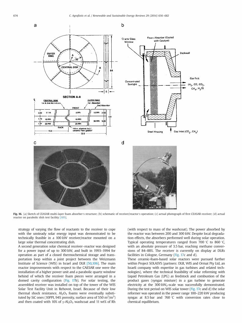
strategy of varying the flow of reactants to the receiver to copewith the unsteady solar energy input was demonstrated to betechnically feasible in a 100 kW receiver/reactor mounted on alarge solar thermal concentrating dish.A second generation solar chemical receiver–reactor was designedfor a power input of up to 300 kW, and built in 1993–1994 foroperation as part of a closed thermochemical storage and trans-portation loop within a joint project between the WeizmannInstitute of Science (WIS) in Israel and DLR [50,106]. The mainreactor improvements with respect to the CAESAR one were theinstallation of a higher power unit and a parabolic quartz windowbehind of which the receiver foam pieces were arranged in adomed cavity configuration (Fig. 17b). For solar testing, theassembled receiver was installed on top of the tower of the WISSolar Test Facility Unit in Rehovot, Israel. Because of their lowthermal shock resistance, Al2O3 foams were eventually substi-tuted by SiC ones (10PPI, 94% porosity, surface area of 550 m2/m3)and then coated with 10% of γ-Al2O3 washcoat and 11 wt% of Rh
(with respect to mass of the washcoat). The power absorbed bythe reactor was between 200 and 300 kW. Despite local degrada-tion effects, the absorbers performed well during solar operation.Typical operating temperatures ranged from 700 1C to 860 1C,with an absolute pressure of 3.5 bar, reaching methane conver-sions of 84–88%. The receiver is currently on display at DLRsfacilities in Cologne, Germany (Fig. 17c and d).These ceramic-foam-based solar reactors were pursued furtherwithin Project SOLASYS (partners: DLR, WIS and Ormat Pty Ltd, anIsraeli company with expertise in gas turbines and related tech-nologies), where the technical feasibility of solar reforming withLiquid Petroleum Gas (LPG) as feedstock and combustion of theproduct gases (syngas mixture) in a gas turbine to generateelectricity at the 300 kWe-scale was successfully demonstrated.During the test period onWIS solar tower (Fig. 17c and d) the solarreformer was operated in the power range 100–220 kW producingsyngas at 8.5 bar and 760 1C with conversion rates close tochemical equilibrium.
Fig. 16. (a) Sketch of CEASAR multi-layer foam absorber′s structure; (b) schematic of receiver/reactor′s operation; (c) actual photograph of first CEASAR receiver; (d) actualreactor on parabolic dish test facility [105].
C. Agrafiotis et al. / Renewable and Sustainable Energy Reviews 29 (2014) 656–682674
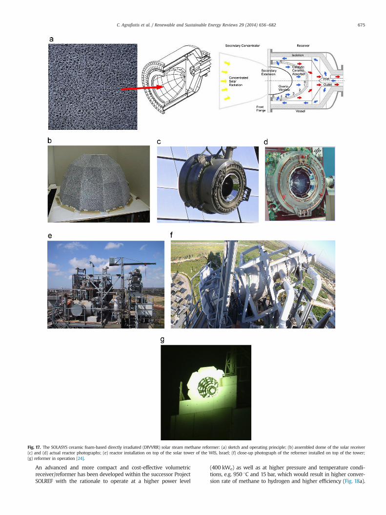
An advanced and more compact and cost-effective volumetricreceiver/reformer has been developed within the successor ProjectSOLREF with the rationale to operate at a higher power level
(400 kWe) as well as at higher pressure and temperature condi-tions, e.g. 950 1C and 15 bar, which would result in higher conver-sion rate of methane to hydrogen and higher efficiency (Fig. 18a).
Fig. 17. The SOLASYS ceramic foam-based directly irradiated (DIVVRR) solar steam methane reformer: (a) sketch and operating principle; (b) assembled dome of the solar receiver(c) and (d) actual reactor photographs; (e) reactor installation on top of the solar tower of the WIS, Israel; (f) close-up photograph of the reformer installed on top of the tower;(g) reformer in operation [24].
C. Agrafiotis et al. / Renewable and Sustainable Energy Reviews 29 (2014) 656–682 675
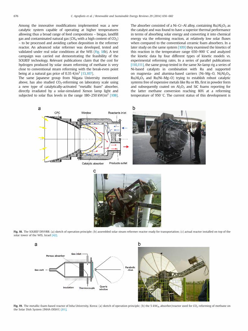
Among the innovative modifications implemented was a newcatalytic system capable of operating at higher temperaturesallowing thus a broad range of feed compositions – biogas, landfillgas and contaminated natural gas (CH4 with a high content of CO2)– to be processed and avoiding carbon deposition in the reformerreactor. An advanced solar reformer was developed, tested andvalidated under real solar conditions at the WIS (Fig. 18b). A testcampaign was carried out demonstrating the feasibility of theSOLREF technology. Relevant publications claim that the cost forhydrogen produced by solar steam reforming of methane is veryclose to conventional steam reforming with the break-even pointbeing at a natural gas price of 0.35 €/m3 [13,107].The same Japanese group from Niigata University mentionedabove, has also studied CO2-reforming on laboratory scale usinga new type of catalytically-activated “metallic foam” absorber,directly irradiated by a solar-simulated Xenon lamp light andsubjected to solar flux levels in the range 180–250 kW/m2 [108].
The absorber consisted of a Ni–Cr–Al alloy, containing Ru/Al2O3 asthe catalyst and was found to have a superior thermal performancein terms of absorbing solar energy and converting it into chemicalenergy via the reforming reaction, at relatively low solar fluxeswhen compared to the conventional ceramic foam absorbers. In alater study on the same system [109] they examined the kinetics ofthis reaction in the temperature range 650–900 1C and analyzedthe kinetic data by four different types of kinetic models vs.experimental reforming rates. In a series of parallel publications[110,111], the same group tested in the same Xe-lamp rig a series ofNi-based catalysts in combination with Ru and supportedon magnesia- and alumina-based carriers (Ni–Mg–O, Ni/Al2O3,Ru/Al2O3 and Ru/Ni–Mg–O) trying to establish robust catalyticsystems free of expensive metals like Ru or Rh, first in powder formand subsequently coated on Al2O3 and SiC foams reporting forthe latter methane conversion reaching 80% at a reformingtemperature of 950 1C. The current status of this development is
Fig. 18. The SOLREF DIVVRR: (a) sketch of operation principle; (b) assembled solar steam reformer reactor ready for transportation; (c) actual reactor installed on top of thesolar tower of the WIS, Israel [42].
Fig. 19. The metallic-foam-based reactor of Inha University, Korea: (a) sketch of operation principle; (b) the 5-kWth absorber/reactor used for CO2 reforming of methane onthe Solar Dish System (INHA-DISH1) [81].
C. Agrafiotis et al. / Renewable and Sustainable Energy Reviews 29 (2014) 656–682676
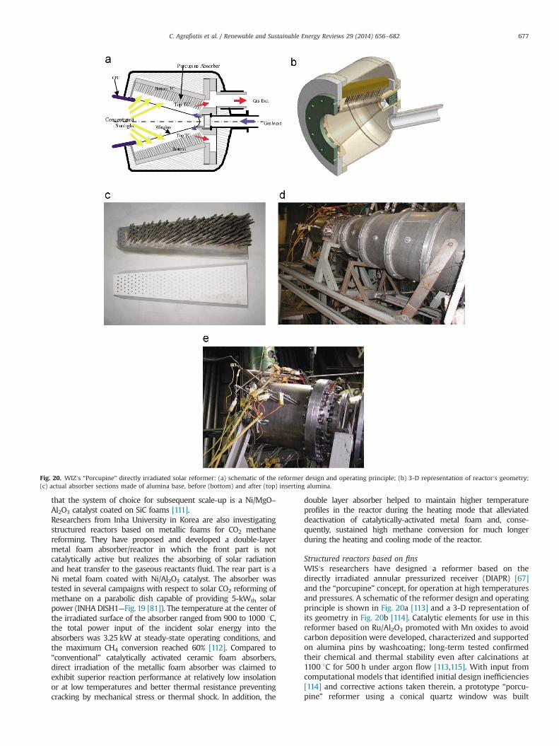
that the system of choice for subsequent scale-up is a Ni/MgO–Al2O3 catalyst coated on SiC foams [111].Researchers from Inha University in Korea are also investigatingstructured reactors based on metallic foams for CO2 methanereforming. They have proposed and developed a double-layermetal foam absorber/reactor in which the front part is notcatalytically active but realizes the absorbing of solar radiationand heat transfer to the gaseous reactants fluid. The rear part is aNi metal foam coated with Ni/Al2O3 catalyst. The absorber wastested in several campaigns with respect to solar CO2 reforming ofmethane on a parabolic dish capable of providing 5-kWth solarpower (INHA DISH1—Fig. 19 [81]). The temperature at the center ofthe irradiated surface of the absorber ranged from 900 to 1000 1C,the total power input of the incident solar energy into theabsorbers was 3.25 kW at steady-state operating conditions, andthe maximum CH4 conversion reached 60% [112]. Compared to“conventional” catalytically activated ceramic foam absorbers,direct irradiation of the metallic foam absorber was claimed toexhibit superior reaction performance at relatively low insolationor at low temperatures and better thermal resistance preventingcracking by mechanical stress or thermal shock. In addition, the
double layer absorber helped to maintain higher temperatureprofiles in the reactor during the heating mode that alleviateddeactivation of catalytically-activated metal foam and, conse-quently, sustained high methane conversion for much longerduring the heating and cooling mode of the reactor.
Structured reactors based on finsWIS′s researchers have designed a reformer based on thedirectly irradiated annular pressurized receiver (DIAPR) [67]and the “porcupine” concept, for operation at high temperaturesand pressures. A schematic of the reformer design and operatingprinciple is shown in Fig. 20a [113] and a 3-D representation ofits geometry in Fig. 20b [114]. Catalytic elements for use in thisreformer based on Ru/Al2O3 promoted with Mn oxides to avoidcarbon deposition were developed, characterized and supportedon alumina pins by washcoating; long-term tested confirmedtheir chemical and thermal stability even after calcinations at1100 1C for 500 h under argon flow [113,115]. With input fromcomputational models that identified initial design inefficiencies[114] and corrective actions taken therein, a prototype “porcu-pine” reformer using a conical quartz window was built
Fig. 20. WIZ′s “Porcupine” directly irradiated solar reformer: (a) schematic of the reformer design and operating principle; (b) 3-D representation of reactor′s geometry;(c) actual absorber sections made of alumina base, before (bottom) and after (top) inserting alumina.
C. Agrafiotis et al. / Renewable and Sustainable Energy Reviews 29 (2014) 656–682 677
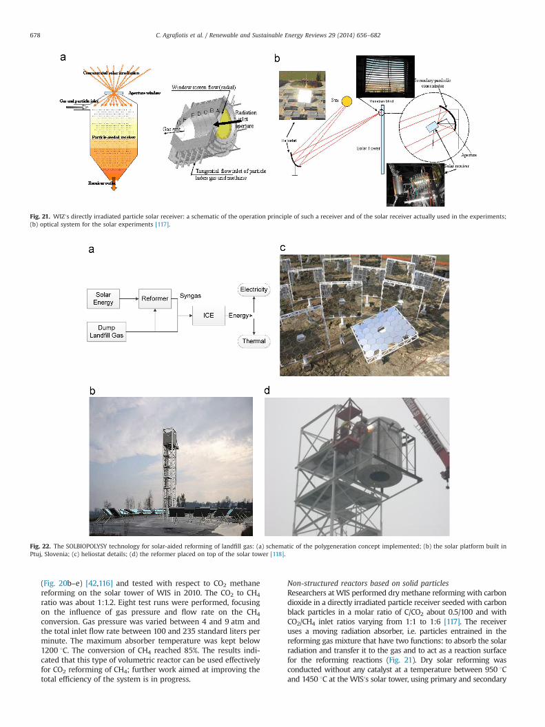
(Fig. 20b–e) [42,116] and tested with respect to CO2 methanereforming on the solar tower of WIS in 2010. The CO2 to CH4
ratio was about 1:1.2. Eight test runs were performed, focusingon the influence of gas pressure and flow rate on the CH4
conversion. Gas pressure was varied between 4 and 9 atm andthe total inlet flow rate between 100 and 235 standard liters perminute. The maximum absorber temperature was kept below1200 1C. The conversion of CH4 reached 85%. The results indi-cated that this type of volumetric reactor can be used effectivelyfor CO2 reforming of CH4; further work aimed at improving thetotal efficiency of the system is in progress.
Non-structured reactors based on solid particlesResearchers at WIS performed dry methane reforming with carbondioxide in a directly irradiated particle receiver seeded with carbonblack particles in a molar ratio of C/CO2 about 0.5/100 and withCO2/CH4 inlet ratios varying from 1:1 to 1:6 [117]. The receiveruses a moving radiation absorber, i.e. particles entrained in thereforming gas mixture that have two functions: to absorb the solarradiation and transfer it to the gas and to act as a reaction surfacefor the reforming reactions (Fig. 21). Dry solar reforming wasconducted without any catalyst at a temperature between 950 1Cand 1450 1C at the WIS′s solar tower, using primary and secondary
Fig. 21. WIZ′s directly irradiated particle solar receiver: a schematic of the operation principle of such a receiver and of the solar receiver actually used in the experiments;(b) optical system for the solar experiments [117].
Fig. 22. The SOLBIOPOLYSY technology for solar-aided reforming of landfill gas: (a) schematic of the polygeneration concept implemented; (b) the solar platform built inPtuj, Slovenia; (c) heliostat details; (d) the reformer placed on top of the solar tower [118].
C. Agrafiotis et al. / Renewable and Sustainable Energy Reviews 29 (2014) 656–682678
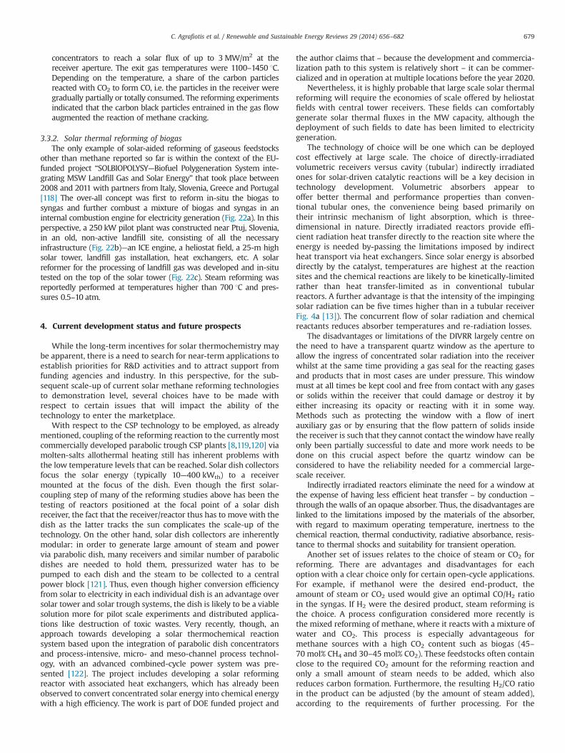
concentrators to reach a solar flux of up to 3 MW/m2 at thereceiver aperture. The exit gas temperatures were 1100–1450 1C.Depending on the temperature, a share of the carbon particlesreacted with CO2 to form CO, i.e. the particles in the receiver weregradually partially or totally consumed. The reforming experimentsindicated that the carbon black particles entrained in the gas flowaugmented the reaction of methane cracking.
3.3.2. Solar thermal reforming of biogasThe only example of solar-aided reforming of gaseous feedstocks
other than methane reported so far is within the context of the EU-funded project “SOLBIOPOLYSY—Biofuel Polygeneration System inte-grating MSW Landfill Gas and Solar Energy” that took place between2008 and 2011 with partners from Italy, Slovenia, Greece and Portugal[118] The over-all concept was first to reform in-situ the biogas tosyngas and further combust a mixture of biogas and syngas in aninternal combustion engine for electricity generation (Fig. 22a). In thisperspective, a 250 kW pilot plant was constructed near Ptuj, Slovenia,in an old, non-active landfill site, consisting of all the necessaryinfrastructure (Fig. 22b)—an ICE engine, a heliostat field, a 25-m highsolar tower, landfill gas installation, heat exchangers, etc. A solarreformer for the processing of landfill gas was developed and in-situtested on the top of the solar tower (Fig. 22c). Steam reforming wasreportedly performed at temperatures higher than 700 1C and pres-sures 0.5–10 atm.
4. Current development status and future prospects
While the long-term incentives for solar thermochemistry maybe apparent, there is a need to search for near-term applications toestablish priorities for R&D activities and to attract support fromfunding agencies and industry. In this perspective, for the sub-sequent scale-up of current solar methane reforming technologiesto demonstration level, several choices have to be made withrespect to certain issues that will impact the ability of thetechnology to enter the marketplace.
With respect to the CSP technology to be employed, as alreadymentioned, coupling of the reforming reaction to the currently mostcommercially developed parabolic trough CSP plants [8,119,120] viamolten-salts allothermal heating still has inherent problems withthe low temperature levels that can be reached. Solar dish collectorsfocus the solar energy (typically 10—400 kWth) to a receivermounted at the focus of the dish. Even though the first solar-coupling step of many of the reforming studies above has been thetesting of reactors positioned at the focal point of a solar dishreceiver, the fact that the receiver/reactor thus has to move with thedish as the latter tracks the sun complicates the scale-up of thetechnology. On the other hand, solar dish collectors are inherentlymodular: in order to generate large amount of steam and powervia parabolic dish, many receivers and similar number of parabolicdishes are needed to hold them, pressurized water has to bepumped to each dish and the steam to be collected to a centralpower block [121]. Thus, even though higher conversion efficiencyfrom solar to electricity in each individual dish is an advantage oversolar tower and solar trough systems, the dish is likely to be a viablesolution more for pilot scale experiments and distributed applica-tions like destruction of toxic wastes. Very recently, though, anapproach towards developing a solar thermochemical reactionsystem based upon the integration of parabolic dish concentratorsand process-intensive, micro- and meso-channel process technol-ogy, with an advanced combined-cycle power system was pre-sented [122]. The project includes developing a solar reformingreactor with associated heat exchangers, which has already beenobserved to convert concentrated solar energy into chemical energywith a high efficiency. The work is part of DOE funded project and
the author claims that – because the development and commercia-lization path to this system is relatively short – it can be commer-cialized and in operation at multiple locations before the year 2020.
Nevertheless, it is highly probable that large scale solar thermalreforming will require the economies of scale offered by heliostatfields with central tower receivers. These fields can comfortablygenerate solar thermal fluxes in the MW capacity, although thedeployment of such fields to date has been limited to electricitygeneration.
The technology of choice will be one which can be deployedcost effectively at large scale. The choice of directly-irradiatedvolumetric receivers versus cavity (tubular) indirectly irradiatedones for solar-driven catalytic reactions will be a key decision intechnology development. Volumetric absorbers appear tooffer better thermal and performance properties than conven-tional tubular ones, the convenience being based primarily ontheir intrinsic mechanism of light absorption, which is three-dimensional in nature. Directly irradiated reactors provide effi-cient radiation heat transfer directly to the reaction site where theenergy is needed by-passing the limitations imposed by indirectheat transport via heat exchangers. Since solar energy is absorbeddirectly by the catalyst, temperatures are highest at the reactionsites and the chemical reactions are likely to be kinetically-limitedrather than heat transfer-limited as in conventional tubularreactors. A further advantage is that the intensity of the impingingsolar radiation can be five times higher than in a tubular receiverFig. 4a [13]). The concurrent flow of solar radiation and chemicalreactants reduces absorber temperatures and re-radiation losses.
The disadvantages or limitations of the DIVRR largely centre onthe need to have a transparent quartz window as the aperture toallow the ingress of concentrated solar radiation into the receiverwhilst at the same time providing a gas seal for the reacting gasesand products that in most cases are under pressure. This windowmust at all times be kept cool and free from contact with any gasesor solids within the receiver that could damage or destroy it byeither increasing its opacity or reacting with it in some way.Methods such as protecting the window with a flow of inertauxiliary gas or by ensuring that the flow pattern of solids insidethe receiver is such that they cannot contact the window have reallyonly been partially successful to date and more work needs to bedone on this crucial aspect before the quartz window can beconsidered to have the reliability needed for a commercial large-scale receiver.
Indirectly irradiated reactors eliminate the need for a window atthe expense of having less efficient heat transfer – by conduction –
through the walls of an opaque absorber. Thus, the disadvantages arelinked to the limitations imposed by the materials of the absorber,with regard to maximum operating temperature, inertness to thechemical reaction, thermal conductivity, radiative absorbance, resis-tance to thermal shocks and suitability for transient operation.
Another set of issues relates to the choice of steam or CO2 forreforming. There are advantages and disadvantages for eachoption with a clear choice only for certain open-cycle applications.For example, if methanol were the desired end-product, theamount of steam or CO2 used would give an optimal CO/H2 ratioin the syngas. If H2 were the desired product, steam reforming isthe choice. A process configuration considered more recently isthe mixed reforming of methane, where it reacts with a mixture ofwater and CO2. This process is especially advantageous formethane sources with a high CO2 content such as biogas (45–70 mol% CH4 and 30–45 mol% CO2). These feedstocks often containclose to the required CO2 amount for the reforming reaction andonly a small amount of steam needs to be added, which alsoreduces carbon formation. Furthermore, the resulting H2/CO ratioin the product can be adjusted (by the amount of steam added),according to the requirements of further processing. For the
C. Agrafiotis et al. / Renewable and Sustainable Energy Reviews 29 (2014) 656–682 679
utilization of biogas this constitutes an attractive possibility forupgrading the heating value. That way, combustion difficultieswith biogas at low engine loads can be reduced [35,123–126].
Even though it is generally accepted that with current invest-ment costs all CSP-aided solar fuels production technologies dorequire a public support strategy for their deployment into themarket [127], one of the major obstacles to their commercializationis the lack of long-term, committed, industrial financial support.Such a support is necessary for not only the initial erection butespecially the long-term operation of a demonstration plant thatwill help in identifying particular technology advantages as well asdrawbacks. At least up until now, technologies that have reachedthe status of solar platform-scale tests have done so through thefinancial support of EU- or national governments-funded projects;however due to time limitations in most of the cases specific sub-components of a full solar plant are tested and validated and notthe integrated process as a whole. On the other hand the oftenintermittent nature of this funding, results in stalling of the devel-opment endeavour before reaching the status of e.g. an automatedprocess, producing long-term experimental results. In this perspec-tive, perhaps “technically simpler” concepts like, for instance, thetubular indirectly-heated (“alllothermal”) reformers employed in theASTERIX project, might be more attractive for large-scale implemen-tation and demonstration of the technology.
In conclusion, significant progress has been made through theresearch efforts described above and the solar driven steamreforming of methane has been demonstrated at pilot scale. Thetechnologies for both DIVRR and tubular reactors are both ready forsmall commercial scale installations, and it is anticipated that plantsin the 1–5 MWth region will be constructed in Australia and Europewithin the next couple of years. The transitional nature of thistechnology – coupling renewable solar thermal energy and con-ventional fossil fuels to make either a synthesis gas or hydrogen – isseen as a key first step on the path to sustainable hydrogen andenergy production.
References
[1] Liu K, Song C, Subramani V. Hydrogen and syngas production and purifica-tion technologies. Wiley-AIChE; 2010.
[2] Mueller-Langer F, Tzimas E, Kaltschmitt M, Peteves S. Techno-economicassessment of hydrogen production processes for the hydrogen economyfor the short and medium term. International Journal of Hydrogen Energy2007;32:3797–810.
[3] Rostrup-Nielsen JR. Syngas in perspective. Catalysis Today 2002;71:243–7.[4] Rostrup-Nielsen JR, Sehested J, Nørskov JK. Hydrogen and synthesis gas by
steam- and CO2 reforming. Advances in Catalysis 200265–139.[5] Graves C, Ebbesen SD, Mogensen M, Lackner KS. Sustainable hydrocarbon
fuels by recycling CO2 and H2O with renewable or nuclear energy. Renewableand Sustainable Energy Reviews 2011;15:1–23.
[6] Steinfeld A. Solar thermochemical production of hydrogen––a review. SolarEnergy 2005;78:603–15.
[7] Koumi Ngoh S, Njomo D. An overview of hydrogen gas production from solarenergy. Renewable and Sustainable Energy Reviews 2012;16:6782–92.
[8] Kodama T. High-temperature solar chemistry for converting solar heat tochemical fuels. Progress in Energy and Combustion Science 2003;29:567–97.
[9] Tamaura Y, Steinfeld A, Kuhn P, Ehrensberger K. Production of solar hydrogenby a novel, 2-step, water-splitting thermochemical cycle. Energy 1995;20:325–30.
[10] Agrafiotis C, Roeb M, Konstandopoulos AG, Nalbandian L, Zaspalis V, Sattler C,et al. Solar water splitting for hydrogen production with monolithic reactors.Solar Energy 2005;79:409–21.
[11] Anikeev VI, Bobrin AS, Ortner J, Schmidt S, Funken KH, Kuzin NA. Catalyticthermochemical reactor/receiver for solar reforming of natural gas: designand performance. Solar Energy 1998;63:97–104.
[12] Hirsch D, Epstein M, Steinfeld A. The solar thermal decarbonization ofnatural gas. International Journal of Hydrogen Energy 2001;26:1023–33.
[13] Möller S, Kaucic D, Sattler C. Hydrogen production by solar reforming ofnatural gas: a comparison study of two possible process configurations.Journal of Solar Energy Engineering 2006;128:16–23.
[14] Zedtwitz P, Petrasch J, Trommer D, Steinfeld A. Hydrogen production via thesolar thermal decarbonization of fossil fuels. Solar Energy 2006;80:1333–7.
[15] Dahl JK, Buechler KJ, Weimer AW, Lewandowski A, Bingham C. Solar-thermaldissociation of methane in a fluid-wall aerosol flow reactor. InternationalJournal of Hydrogen Energy 2004;29:725–36.
[16] Abanades S, Flamant G. Production of hydrogen by thermal methanesplitting in a nozzle-type laboratory-scale solar reactor. International Journalof Hydrogen Energy 2005;30:843–53.
[17] Abanades S, Flamant G. Solar hydrogen production from the thermal splittingof methane in a high temperature solar chemical reactor. Solar Energy2006;80:1321–32.
[18] Flechsenhar M, Sasse C. Solar gasification of biomass using oil shale and coalas candidate materials. Energy 1995;20:803–10.
[19] Trommer D, Noembrini F, Fasciana M, Rodriguez D, Morales A, Romero M,et al. Hydrogen production by steam-gasification of petroleum coke usingconcentrated solar power—I. Thermodynamic and kinetic analyses. Interna-tional Journal of Hydrogen Energy 2005;30:605–18.
[20] Piatkowski N, Wieckert C, Weimer AW, Steinfeld A. Solar-driven gasificationof carbonaceous feedstock—a review. Energy & Environmental Science2011;4:73–82.
[21] Steinfeld A, Palumbo R. Solar thermochemical process technology. In:Meyers RA, editor. Encyclopedia of physical science and technology.Academic Press; 2001. p. 237–56.
[22] Steinfeld, A. Thermochemical production of syngas using concentrated solarenergy. Annual review of heat transfer: Begell House Inc.; 2012. 255–275.
[23] Roeb M, Säck JP, Rietbrock P, Prahl C, Schreiber H, Neises M, et al. Testoperation of a 100 kW pilot plant for solar hydrogen production from wateron a solar tower. Solar Energy 2011;85:634–44.
[24] Sattler C. Hydrogen production by the solar-driven steam reforming ofmethane. In: Stolten D, editor. Hydrogen and fuel cells: fundamentals,technologies and applications. Weinheim: Wiley-VCH; 2010.
[25] Dry ME. High quality diesel via the Fischer–Tropsch process–a review.Journal of Chemical Technology and Biotechnology 2001;77:43–50.
[26] Bartholomew CH, Farrauto RJ. Fundamentals of industrial catalytic processes.2nd ed. Hoboken, N.J.: Wiley; 2006.
[27] Huber GW, Iborra S, Corma A. Synthesis of transportation fuels from bio-mass: chemistry, catalysts, and engineering. Chemical Reviews 2006;106:4044–98.
[28] Semelsberger TA, Borup RL, Greene HL. Dimethyl ether (DME) as analternative fuel. Journal of Power Sources 2006;156:497–511.
[29] Aricò AS, Baglio V, Antonucci V. Direct methanol fuel cells: history, statusand perspectives. Electrocatalysis of direct methanol fuel cells. Wiley-VCHVerlag GmbH & Co. KGaA; 1–78.
[30] Spath PL, Dayton DC. Preliminary screening—technical and economic assess-ment of synthesis gas to fuels and chemicals with emphasis on the potentialfor biomass-derived syngas. Golden, Colorado: U.S. Department of EnergyLaboratory; 160.
[31] Turpeinen E, Raudaskoski R, Pongrácz E, Keiski R. Thermodynamic analysis ofconversion of alternative hydrocarbon-based feedstocks to hydrogen. Inter-national Journal of Hydrogen Energy 2008;33:6635–43.
[32] Wang S, Lu CG, Millar GJ. Carbon dioxide reforming of methane to producesynthesis gas over metal-supported catalysts: state of the art. Energy & fuels1996;10:896–904.
[33] Hoguet J-C, Karagiannakis GP, Valla JA, Agrafiotis CC, Konstandopoulos AG.Gas and liquid phase fuels desulphurization for hydrogen production viareforming processes. International Journal of Hydrogen Energy 2009;34:4953–62.
[34] Christensen TS. Adiabatic prereforming of hydrocarbons—an important stepin syngas production. Applied Catalysis A: General 1996;138:285–309.
[35] Sun Y, Ritchie T, Hla SS, McEvoy S, Stein W, Edwards JH. Thermodynamicanalysis of mixed and dry reforming of methane for solar thermal applica-tions. Journal of Natural Gas Chemistry 2011;20:568–76.
[36] Tomishige K, Chen Y, Fujimoto K. Studies on carbon deposition in CO2 reformingof CH4 over Nickel–Magnesia solid solution catalysts. Journal of Catalysis1999;181:91–103.
[37] Lemonidou A, Goula M, Vasalos I. Carbon dioxide reforming of methane over5 wt% nickel calcium aluminate catalysts—effect of preparation method.Catalysis Today 1998;46:175–83.
[38] Gadalla AM, Bower B. The role of catalyst support on the activity of nickel forreforming methane with CO2. Chemical Engineering Science 1988;43:3049–62.
[39] Lemonidou AA, Vasalos IA. Carbon dioxide reforming of methane over 5 wt%Ni/CaO–Al2O3 catalyst. Applied Catalysis A: General 2002;228:227–35.
[40] Berman A, Karni RK, Epstein M. Kinetics of steam reforming of methane onRu/Al2O3 catalyst promoted with Mn oxides. Applied Catalysis A: General2005;282:73–83.
[41] Sehested J. Four challenges for nickel steam-reforming catalysts. CatalysisToday 2006;111:103–10.
[42] Epstein M. Solar thermal reforming of methane. SFERA Winter School.Switzerland. Zürich; 2011.
[43] Rostrup-Nielsen JR. Catalytic steam reforming. In: Anderson JR, editor.Catalysis: Science and Technology. Springer-Verlag; 1984.
[44] Kikuchi E. Palladium/ceramic membranes for selective hydrogen permeationand their application to membrane reactor. Catalysis Today 1995;25:333–7.
[45] Aasberg-Petersen K, Nielsen CS, Jørgensen SL. Membrane reforming forhydrogen. Catalysis Today 1998;46:193–201.
[46] Aasberg-Petersen K, Dybkjær I, Ovesen C, Schjødt N, Sehested J, Thomsen S.Natural gas to synthesis gas–Catalysts and catalytic processes. Journal ofNatural Gas Science and Engineering 2011;3:423–59.
C. Agrafiotis et al. / Renewable and Sustainable Energy Reviews 29 (2014) 656–682680
[47] Romero M, Steinfeld A. Concentrating solar thermal power and thermo-chemical fuels. Energy & Environmental Science 2012;5:9234.
[48] Agrafiotis CC, Pagkoura C, Lorentzou S, Kostoglou M, Konstandopoulos AG.Hydrogen production in solar reactors. Catalysis Today 2007;127:265–77.
[49] Apt J, Newcomer A, Lave LB, Douglas S, Morris Dunn L. DOE NETL-20081331_Final report, An engineering-economic analysis of syngas storage.2008.
[50] Tamme R, Buck R, Epstein M, Fisher U, Sugarmen C. Solar upgrading of fuelsfor generation of electricity. Journal of Solar Energy Engineering2001;123:160–3.
[51] Edwards JH, Do KT, Maitra AM, Schuck S, Fok W, Stein W. The use of solar-based CO2/CH4 reforming for reducing greenhouse gas emissions during thegeneration of electricity and process heat. Energy Conversion and Manage-ment 1996;37:1339–44.
[52] Chubb TA. Characteristics of CO2–CH4 reforming-methanation cycle relevantto the solchem thermochemical power system. Solar Energy 1980;24:341–5.
[53] Jensen J, Poulsen J, Andersen N. From coal to clean energy. NitrogenþSyngas2010:310.
[54] Cybulski A, Moulijn JA. Structured catalysts and reactors. CRC; 2005.[55] Karni J, Kribus A, Rubin R, Doron P. The Porcupine: a novel high-flux
absorber for volumetric solar receivers. Journal of Solar Energy Engineer-ing—Transactions of the ASME 1998;120:85–95.
[56] Bilgen E, Galindo J. High temperature solar reactors for hydrogen production.International Journal of Hydrogen Energy 1981;6:139–52.
[57] Richardson J, Paripatyadar S, Shen J. Dynamics of a sodium heat pipereforming reactor. AIChE Journal 1988;34:743–52.
[58] Olalde G, Peube J. Etude expérimentale d′un récepteur solaire en nid d′abeilles pour le chauffage solaire des gaz à haute température. Revue dePhysique Appliquée 1982;17:563–8.
[59] Fend T, Hoffschmidt B, Pitz-Paal R, Reutter O, Rietbrock P. Porous materialsas open volumetric solar receivers: experimental determination of thermo-physical and heat transfer properties. Energy 2004;29:823–33.
[60] Fend T, Pitz-Paal R, Reutter O, Bauer J, Hoffschmidt B. Two novel high-porosity materials as volumetric receivers for concentrated solar radiation.Solar Energy Materials and Solar Cells 2004;84:291–304.
[61] Ávila-Marín AL. Volumetric receivers in solar thermal power plants withcentral receiver system technology: a review. Solar Energy 2011;85:891–910.
[62] Pitz-Paal R, Hoffschmidt B, Böhmer M, Becker M. Experimental and numer-ical evaluation of the performance and flow stability of different types ofopen volumetric absorbers under non-homogeneous irradiation. SolarEnergy 1997;60:135–50.
[63] Chavez JM, Chaza C. Testing of a porous ceramic absorber for a volumetric airreceiver. Solar Energy Materials 1991;24:172–81.
[64] Agrafiotis CC, Mavroidis I, Konstandopoulos AG, Hoffschmidt B, Stobbe P,Romero M, et al. Evaluation of porous silicon carbide monolithic honey-combs as volumetric receivers/collectors of concentrated solar radiation.Solar Energy Materials and Solar Cells 2007;91:474–88.
[65] Sanchez M, Sevilla Portillo A. Review of PSA activities in the area of solarthermal energy conversion. Solar Energy Materials 1991;24:683–95.
[66] Hennecke K, Schwarzbözl P, Koll G, Beuter M, Hoffschmidt B, Göttsche J, et al.The solar power Tower Jülich—a solar thermal power plant for test anddemonstration of air receiver technology. In: Proceedings of ISES worldcongress; 2007 (vol I–vol V): Springer; 2009. p. 1749–53.
[67] Karni J, Kribus A, Doron P, Rubin R, Fiterman A, Sagie D. The DIAPR: a high-pressure, high-temperature solar receiver. Journal of Solar Energy Engineer-ing 1997;119:74–8.
[68] Heck RM, Farrauto RJ, Gulati ST. Catalytic air pollution control. Wiley OnlineLibrary; 1995.
[69] Geus JW, Van Giezen JC. Monoliths in catalytic oxidation. Catalysis Today1999;47:169–80.
[70] McCrary JH, McCrary GE, Chubb TA, Nemecek JJ, Simmons DE. An experi-mental study of the CO2–CH4 reforming-methanation cycle as a mechanismfor converting and transporting solar energy. Solar Energy 1982;29:141–51.
[71] Anikeev VI, Kirillov VA. Basic design principles and some methods ofinvestigation of catalytic reactors-receivers of solar radiation. Solar EnergyMaterials 1991;24:633–46.
[72] Anikeev V, Bobrin A, Khanaev V, Kirillov V. Chemical heat regeneration inpower plants. International Journal of Energy Research 1993;17:233–42.
[73] Anikeev V, Parmon V, Kirillov V, Zamaraev K. Theoretical and experimentalstudies of solar catalytic power plants based on reversible reactions withparticipation of methane and synthesis gas. International Journal of Hydro-gen Energy 1990;15:275–86.
[74] Spiewak I, Tyner CE, Langnickel U. SAND93—1959; UC-237—applications ofsolar reforming technology. Albuquerque, NewMexico: USA: Sandia NationalLaboratories; 1993.
[75] Hogan R, Skocypec R, Diver R, Fish J, Garrait M, Richardson J. A directabsorber reactor/receiver for solar thermal applications. Chemical Engineer-ing Science 1990;45:2751–8.
[76] Levy M, Rubin R, Rosin H, Levitan R. Methane reforming by direct solarirradiation of the catalyst. Energy 1992;17:749–56.
[77] Levy M, Rosin H, Levitan R. Chemical reactions in a solar furnace by directsolar irradiation of the catalyst. Journal of Solar Energy Engineerin 1989:111(United States).
[78] Kirillov VA. Catalyst application in solar thermochemistry. Solar Energy1999;66:143–9.
[79] Kumar P, Sun Y, Idem RO. Comparative study of Ni-based mixed oxidecatalyst for carbon dioxide reforming of methane. Energy & Fuels2008;22:3575–82.
[80] Abanades S, Flamant G. Experimental study and modeling of a high-temperature solar chemical reactor for hydrogen production from methanecracking. International Journal of Hydrogen Energy 2007;32:1508–15.
[81] Meier A. SolarPaces annual report—Task II solar chemistry research. 2010.[82] Böhmer M, Langnickel U, Sanchez M. Solar steam reforming of methane.
Solar Energy Materials 1991;24:441–8.[83] Epstein M, Spiewak I, Segal A, Levy I, Lieberman D, Meri M, et al. Solar
experiments with a tubular reformer. In: Proceedings of the eighth interna-tional symposium on solar thermal concentrating technologies. Köln,Germany 1996. p. 1209–29.
[84] Segal A, Epstein M. Solar ground reformer. Solar Energy 2003;75:479–90.[85] McNaughton R. Solar steam reforming using a closed cycle gaseous heat
transfer loop. In: Proceedings of 2012 solarPACES, concentrating solar powerand chemical energy systems conference Marrakech, Morocco, September11th–14th, 2012.
[86] McNaughton R, Stein W. Improving efficiency of power generation from solarthermal natural gas reforming. In: Proceedings of 15th international solarPACES concentrating solar power symposium,. Berlin, Germany, September15th–18th; 2009.
[87] Stein W. Hydrogen production by the solar-driven steam reforming ofmethane. In: Garche J, editor. Encyclopedia of electrochemical powersources. Elsevier; 2009.
[88] Paripatyadar SA, Richardson JT. Cyclic performance of a sodium heat pipe,solar reformer. Solar Energy 1988;41:475–85.
[89] Diver RB, Fish JD, Levitan R, Levy M, Meirovitch E, Rosin H, et al. Solar test ofan integrated sodium reflux heat pipe receiver/reactor for thermochemicalenergy transport. Solar Energy 1992;48:21–30.
[90] Hering W, Stieglitz R, Wetzel T. Application of liquid metals for solar energysystems. In: EPJ web of conferences: EDP sciences; 2012.
[91] Burgaleta JI, Arias S, Ramirez D. GEMASOLAR, the first tower thermosolarcommercial plant with molten salt storage. In: Proceedings of 2011 solarPACES, concentrating solar power and chemical energy systems conferenceGranada, Spain September 20th–23rd, 2011.
[92] Kodama T, Koyanagi T, Shimizu T, Kitayama Y. CO2 reforming of methane in amolten carbonate salt bath for use in solar thermochemical processes.Energy & Fuels 2001;15:60–5.
[93] Al-Ali K. Solar upgrade of methane using dry reforming in direct contactbubble reactor. In: Proceedings of 2012 SolarPACES, concentrating solarpower and chemical energy systems conference Marrakech, Morocco,September 11th–14th, 2012.
[94] Shimizu T, Shimizu K, Kitayama Y, Kodama T. Thermochemical methanereforming using WO3 as an oxidant below 1173 K by a solar furnacesimulator. Solar Energy 2001;71:315–24.
[95] Gokon N, Oku Y, Kaneko H, Tamaura Y. Methane reforming with CO2 inmolten salt using FeO catalyst. Solar Energy 2002;72:243–50.
[96] Kodama T, Isobe Y, Kondoh Y, Yamaguchi S, Shimizu KI. Ni/ceramic/molten-salt composite catalyst with high-temperature thermal storage for use insolar reforming processes. Energy 2004;29:895–903.
[97] Hatamachi T, Kodama T, Isobe Y. Carbonate composite catalyst with high-temperature thermal storage for use in solar tubular reformers. Journal ofSolar Energy Engineering 2005;127:396–400.
[98] Kodama T, Gokon N, Inuta S, Yamashita S, Seo T. Molten-salt tubularabsorber/reformer (MoSTAR) project: the thermal storage media of Na2CO3–
MgO composite materials. Journal of Solar Energy Engineering 2009:131.[99] Giaconia A, de Falco M, Caputo G, Grena R, Tarquini P, Marrelli L. Solar steam
reforming of natural gas for hydrogen production using molten salt heatcarriers. AIChE Journal 2008;54:1932–44.
[100] De Falco M, Giaconia A, Marrelli L, Tarquini P, Grena R, Caputo G. Enrichedmethane production using solar energy: an assessment of plant perfor-mance. International Journal of Hydrogen Energy 2009;34:98–109.
[101] De Falco M, Piemonte V. Solar enriched methane production by steamreforming process: reactor design. International Journal of Hydrogen Energy2011;36:7759–62.
[102] Dahl JK, Tamburini J, Weimer AW, Lewandowski A, Pitts R, Bingham C. Solar-thermal processing of methane to produce hydrogen and syngas. Energy &Fuels 2001;15:1227–32.
[103] Dahl JK, Weimer AW, Lewandowski A, Bingham C, Bruetsch F, Steinfeld A. Dryreforming of methane using a solar-thermal aerosol flow reactor. Industrial &Engineering Chemistry Research 2004;43:5489–95.
[104] Fend T, Pitz-Paal R, Hoffschmidt B, Reutter O. Cellular ceramics: structure,manufacturing, properties and applications. In: Scheffler M, Colombo P,editors. Weinheim: Wiley-VCH Verlag GmbH &Co; 2006. p. 523–46.
[105] Buck R, Muir JF, Hogan RE. Carbon dioxide reforming of methane in a solarvolumetric receiver/reactor: the CAESAR project. Solar Energy Materials1991;24:449–63.
[106] Wörner A, Tamme R. CO2 reforming of methane in a solar driven volumetricreceiver–reactor. Catalysis Today 1998;46:165–74.
[107] Pregger T, Graf D, Krewitt W, Sattler C, Roeb M, Möller S. Prospects of solarthermal hydrogen production processes. International Journal of HydrogenEnergy 2009;34:4256–67.
[108] Kodama T, Kiyama A, Shimizu KI. Catalytically activated metal foam absorberfor light-to-chemical energy conversion via solar reforming of methane.Energy & Fuels 2003;17:13–7.
C. Agrafiotis et al. / Renewable and Sustainable Energy Reviews 29 (2014) 656–682 681
[109] Gokon N, Yamawaki Y, Nakazawa D, Kodama T. Kinetics of methane reformingover Ru/γ-Al2O3-catalyzed metallic foam at 650–900 1C for solar receiver–absorbers. International Journal of Hydrogen Energy 2011;36:203–15.
[110] Kiyama A, Moriyama T, Mizuno O. Solar methane reforming using a new typeof catalytically-activated metallic foam absorber. Journal of Solar EnergyEngineering 2004;126:808.
[111] Gokon N, Yamawaki Y, Nakazawa D, Kodama T. Ni/MgO–Al2O3 and Ni–Mg–Ocatalyzed SiC foam absorbers for high temperature solar reforming ofmethane. International Journal of Hydrogen Energy 2010;35:7441–53.
[112] Lee J, Lee J, Shin I, Seo T. Solar CO2-reforming of methane using a double layerabsorber. In: Proceedings of 2011 SolarPACES, concentrating solar power andchemical energy systems conference Granada, Spain, September 20th–23rd,2011.
[113] Berman A, Karni RK, Epstein M. A new catalyst system for high-temperaturesolar reforming of methane. Energy & Fuels 2006;20:455–62.
[114] Ben-Zvi R, Karni J. Simulation of a volumetric solar reformer. Journal of SolarEnergy Engineering 2007;129:197–204.
[115] Berman A, Karn RK, Epstein M. Steam reforming of methane on a Ru/Al2O3
catalyst promoted with Mn oxides for solar hydrogen production. GreenChemistry 2007;9:626–31.
[116] Rubin R, Karni J. Carbon dioxide reforming of methane in directly irradiatedsolar reactor with porcupine absorber. Journal of Solar Energy Engineering2011:133.
[117] Klein HH, Karni J, Rubin R. Dry methane reforming without a metal catalyst ina directly irradiated solar particle reactor. Journal of Solar Energy Engineering2009;131:021001.
[118] Solbiopolysy. Polygeneration system integrating MSW landfill and solarenergy, ⟨http://solbiopolysy-lro.ung.si/Biofuel⟩, /last accessed on January28th; 2013.
[119] Technology Roadmap: concentrating solar power. International EnergyAgency, OECD/IEA; 2010.
[120] NREL. Concentrating Solar Power Projects, ⟨http://www.nrel.gov/csp/solarpaces/lastaccessed⟩ on January 28th, 2013.
[121] Ozalp N, Kogan A, Epstein M. Solar decomposition of fossil fuels as an optionfor sustainability. International Journal of Hydrogen Energy 2009;34:710–20.
[122] Wengeng R. Integrated solar thermochemical reaction system for highefficiency production of electricity. In: ASME conference energy sustainabil-ity Minneapolis, Minnesota, USA2013.
[123] Jun HJ, Park M-J, Baek S-C, Bae JW, Ha K-S, Jun K-W. Kinetics modeling for themixed reforming of methane over Ni–CeO2/MgAl2O4 catalyst. Journal ofNatural Gas Chemistry 2011;20:9–17.
[124] (Effendi) Zhang A, Hellgardt ZG, Honda K, Yoshida K, Steam T. Reforming of aclean model biogas over Ni/Al2O3 in fluidized-and fixed-bed reactors.Catalysis Today 2002;77:181–9.
[125] Lau C, Tsolakis A, Wyszynski M. Biogas upgrade to syn-gas (H2–CO) via dryand oxidative reforming. International Journal of Hydrogen Energy2011;36:397–404.
[126] Rasi S, Veijanen A, Rintala J. Trace compounds of biogas from different biogasproduction plants. Energy 2007;32:1375–80.
[127] Romero M, Buck R, Pacheco JE. An update on solar central receiver systems,projects, and technologies. Journal of Solar Energy Engineering 2002;124:98.
C. Agrafiotis et al. / Renewable and Sustainable Energy Reviews 29 (2014) 656–682682
Related Documents