Analysis of Weaving,
Merging, and Diverging
MovementsCIVL 4162/6162
Weaving, Diverging, Merging Segments
• Weaving – one movement must cross the
path of another along a length of facility
without the aid of signals or other traffic
control devices
• Merging – two separate traffic streams join
to form a single one
• Diverging – one traffic stream separates to
form two separate traffic streams
• Why do we consider these separately from
BFS/Multilane Segments?
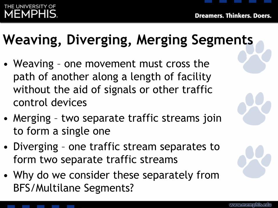
Figure 15.1 Weaving, Merging, and Diverging Movements Illustrated

LOS for W/M/D Segments
• Based on density
Table 15.1 Level-of-Service Criteria for Weaving, Merging, and Diverging Segments
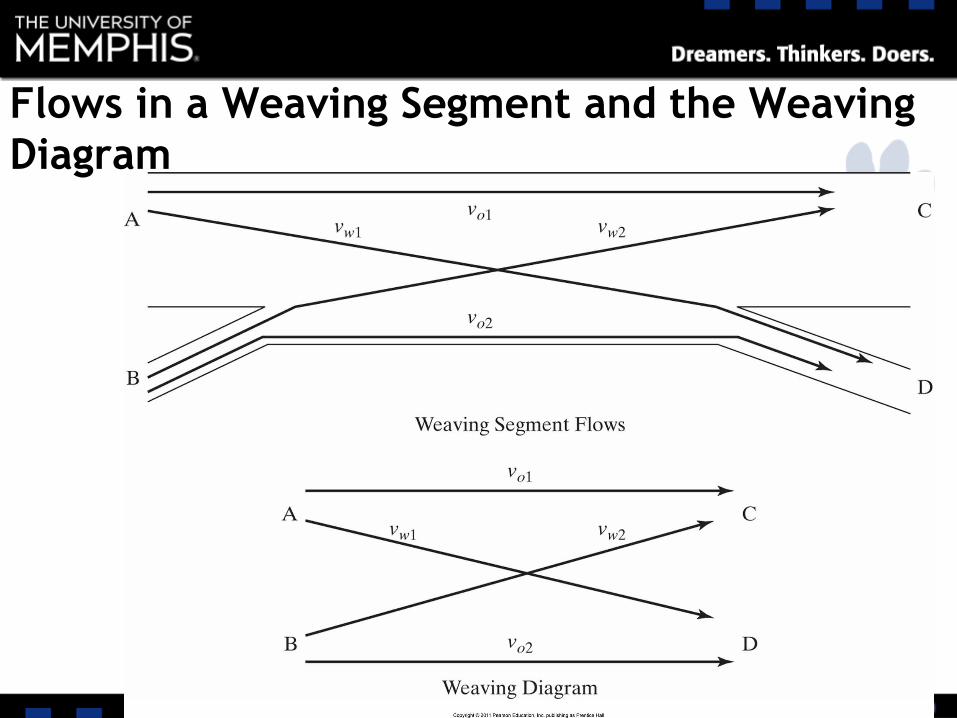
Flows in a Weaving Segment and the Weaving
Diagram
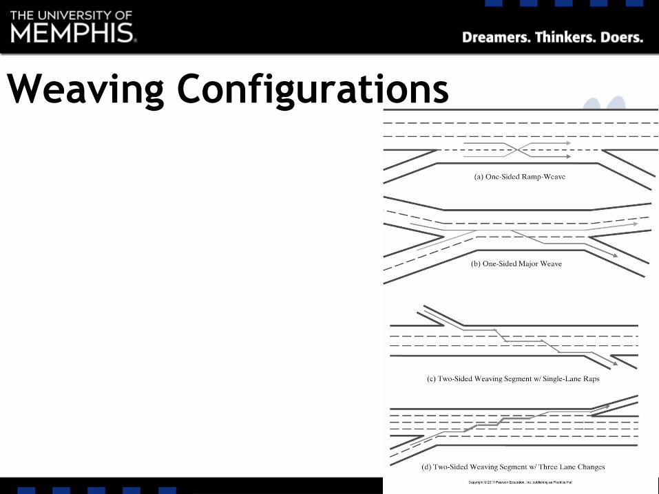
Weaving Configurations
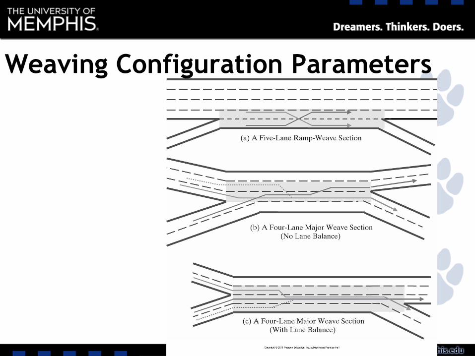
Weaving Configuration Parameters
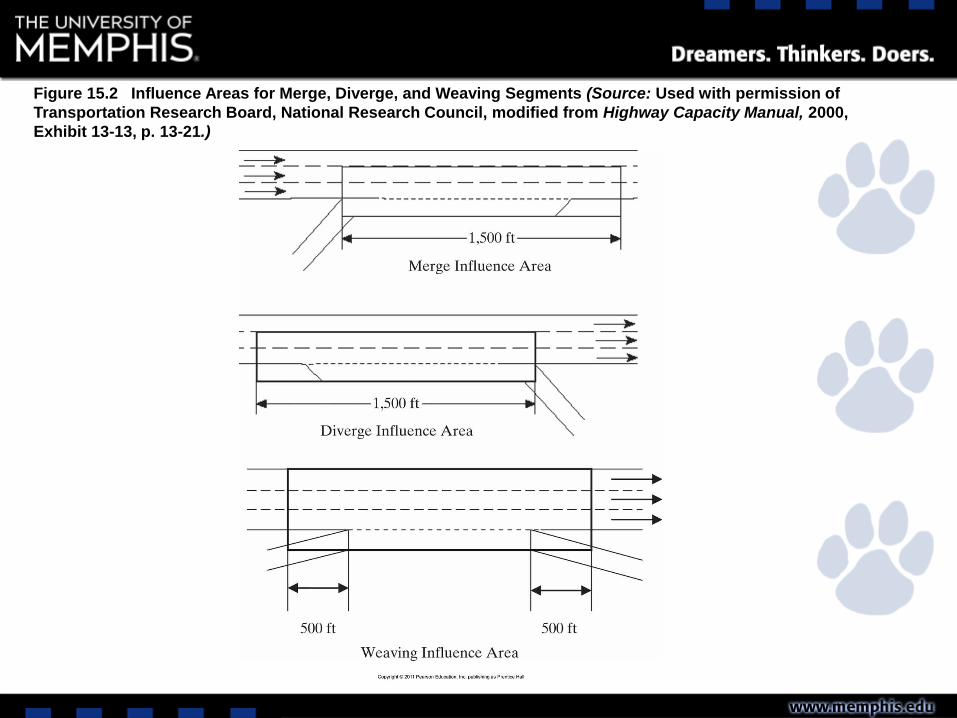
Figure 15.2 Influence Areas for Merge, Diverge, and Weaving Segments (Source: Used with permission of
Transportation Research Board, National Research Council, modified from Highway Capacity Manual, 2000,
Exhibit 13-13, p. 13-21.)
Weaving Analysis- Input Requirements
• Existing roadway and traffic conditions are
required, including:
– Length and width of weaving area
– Number of lanes
– Type of configuration
– Terrain/grade conditions
– FFS
– Hourly volumes
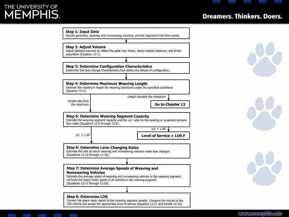
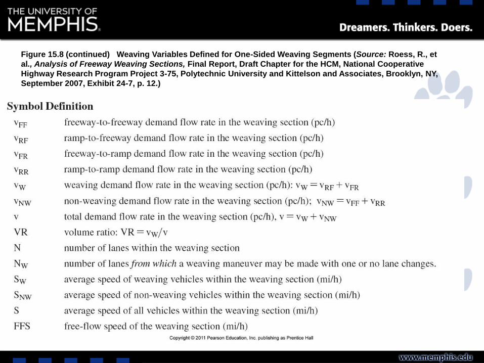
Figure 15.8 (continued) Weaving Variables Defined for One-Sided Weaving Segments (Source: Roess, R., et
al., Analysis of Freeway Weaving Sections, Final Report, Draft Chapter for the HCM, National Cooperative
Highway Research Program Project 3-75, Polytechnic University and Kittelson and Associates, Brooklyn, NY,
September 2007, Exhibit 24-7, p. 12.)
Step-1: Input Data
• Ensure to write all the input data in one place
before analyzing the weaving section
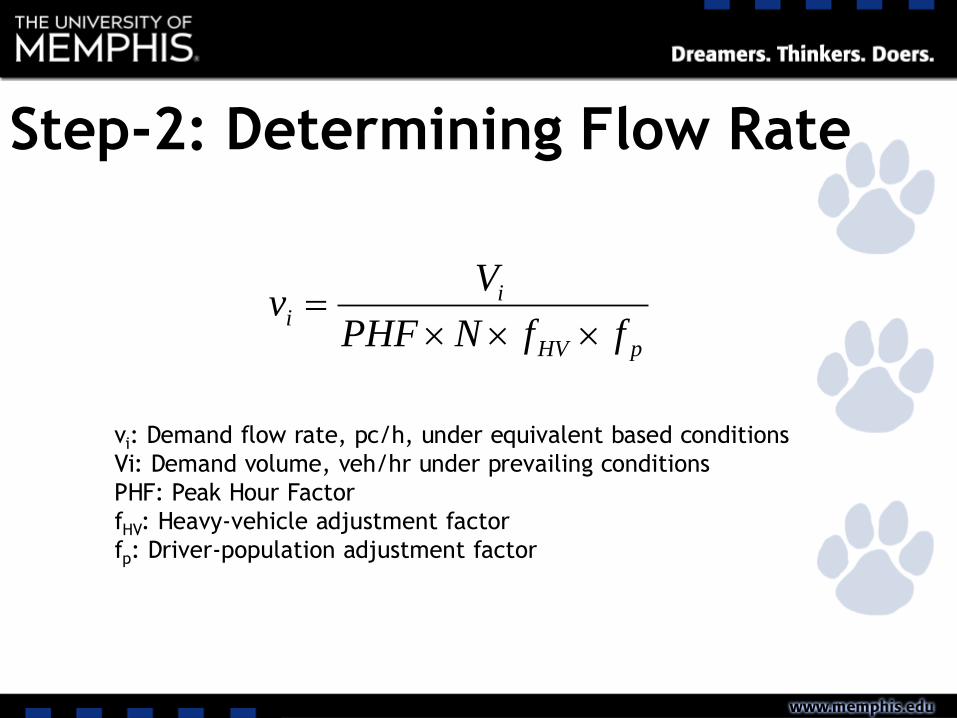
Step-2: Determining Flow Rate
pHV
ii
ffNPHF
Vv
vi: Demand flow rate, pc/h, under equivalent based conditions
Vi: Demand volume, veh/hr under prevailing conditions
PHF: Peak Hour Factor
fHV: Heavy-vehicle adjustment factor
fp: Driver-population adjustment factor
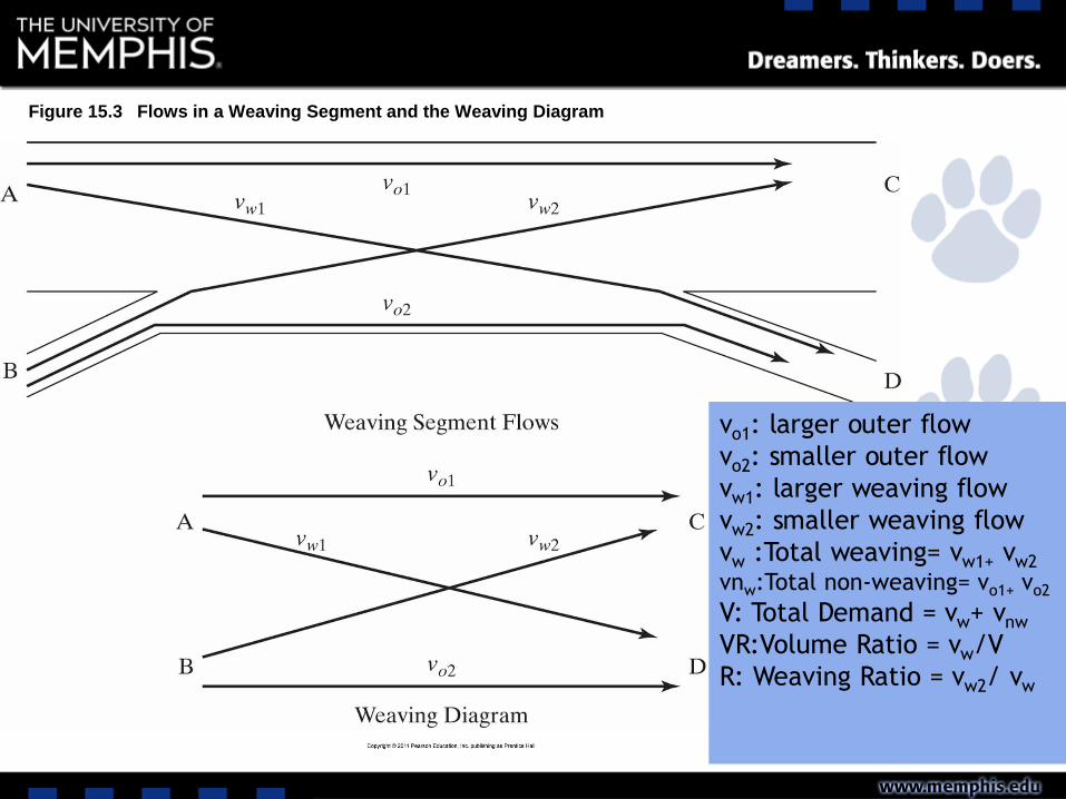
Figure 15.3 Flows in a Weaving Segment and the Weaving Diagram
vo1: larger outer flow
vo2: smaller outer flow
vw1: larger weaving flow
vw2: smaller weaving flow
vw :Total weaving= vw1+ vw2
vnw:Total non-weaving= vo1+ vo2
V: Total Demand = vw+ vnw
VR:Volume Ratio = vw/V
R: Weaving Ratio = vw2/ vw
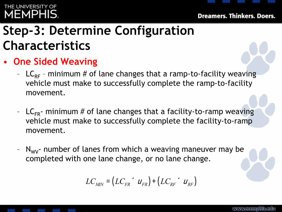
Step-3: Determine Configuration
Characteristics
• One Sided Weaving
– LCRF – minimum # of lane changes that a ramp-to-facility weaving
vehicle must make to successfully complete the ramp-to-facility
movement.
– LCFR- minimum # of lane changes that a facility-to-ramp weaving
vehicle must make to successfully complete the facility-to-ramp
movement.
– NWV- number of lanes from which a weaving maneuver may be
completed with one lane change, or no lane change.
LCMIN = LCFR ´uFR( ) + LCRF ´uRF( )
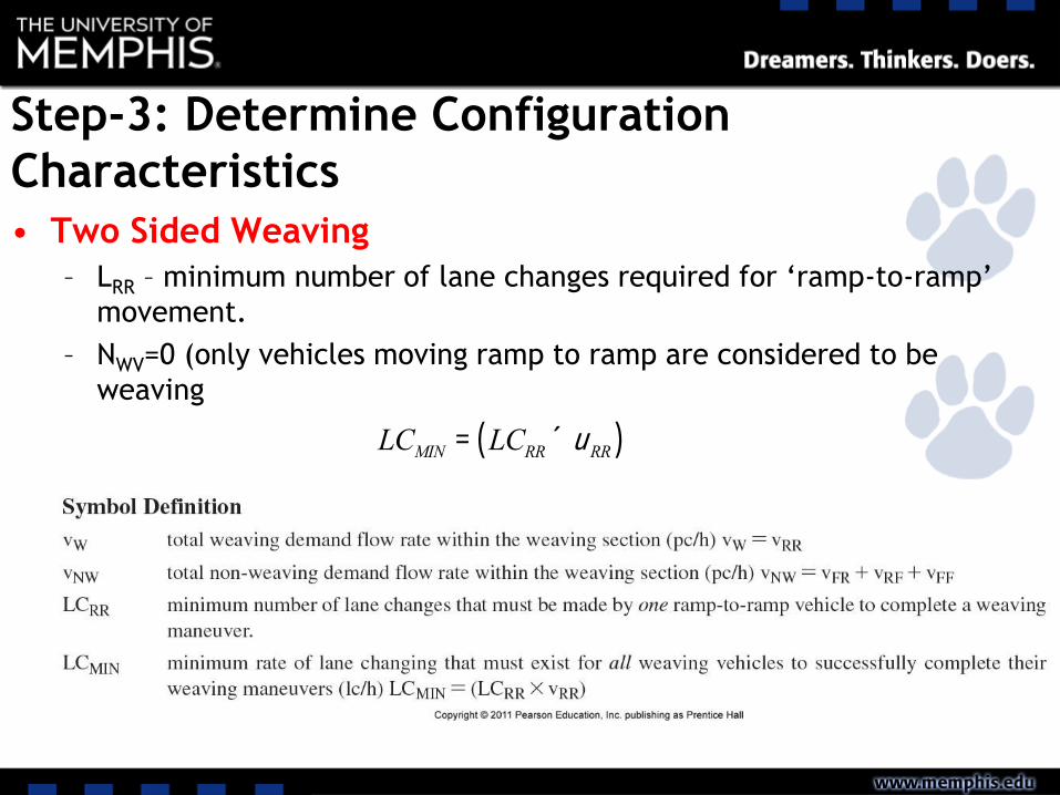
Step-3: Determine Configuration
Characteristics
• Two Sided Weaving
– LRR – minimum number of lane changes required for ‘ramp-to-ramp’
movement.
– NWV=0 (only vehicles moving ramp to ramp are considered to be
weaving
LCMIN = LCRR ´uRR( )
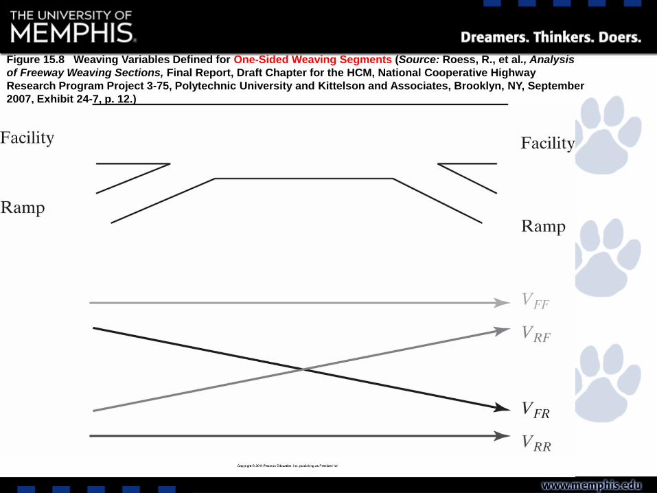
Figure 15.8 Weaving Variables Defined for One-Sided Weaving Segments (Source: Roess, R., et al., Analysis
of Freeway Weaving Sections, Final Report, Draft Chapter for the HCM, National Cooperative Highway
Research Program Project 3-75, Polytechnic University and Kittelson and Associates, Brooklyn, NY, September
2007, Exhibit 24-7, p. 12.)
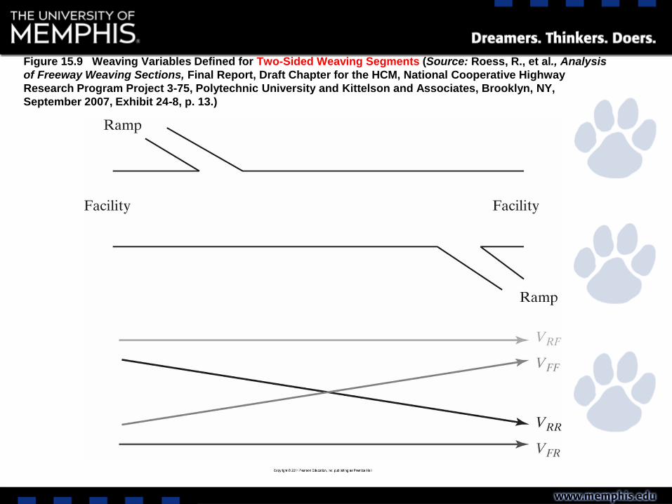
Figure 15.9 Weaving Variables Defined for Two-Sided Weaving Segments (Source: Roess, R., et al., Analysis
of Freeway Weaving Sections, Final Report, Draft Chapter for the HCM, National Cooperative Highway
Research Program Project 3-75, Polytechnic University and Kittelson and Associates, Brooklyn, NY,
September 2007, Exhibit 24-8, p. 13.)
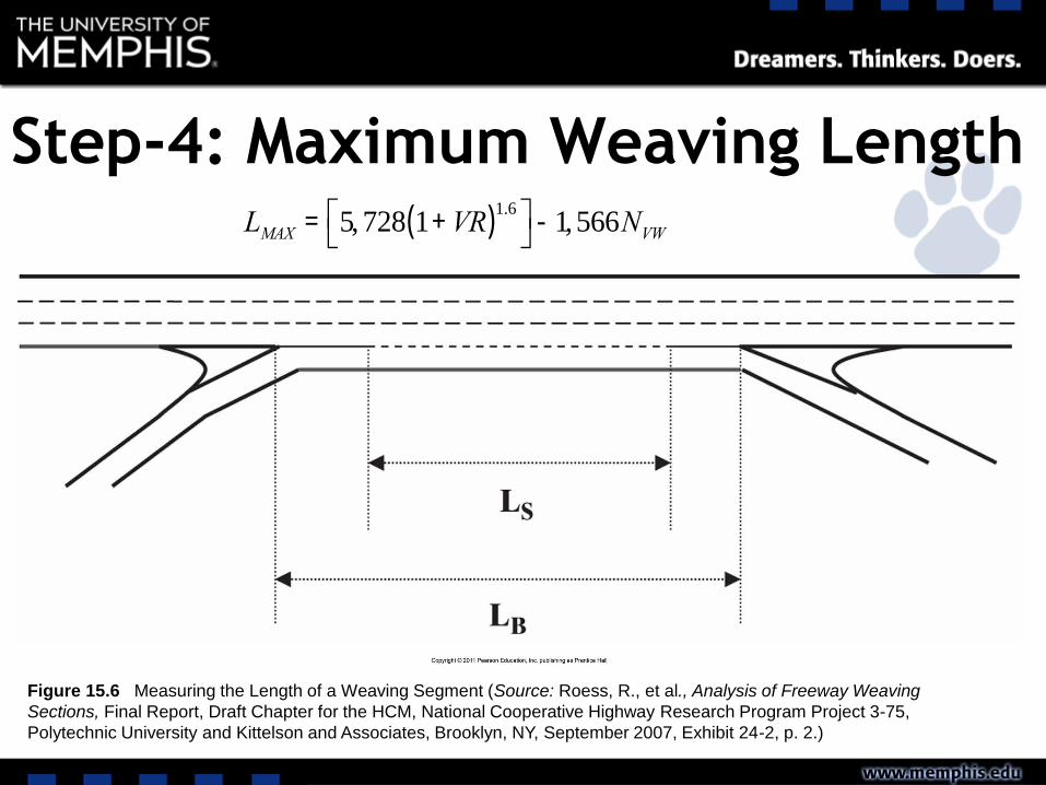
Step-4: Maximum Weaving Length
Figure 15.6 Measuring the Length of a Weaving Segment (Source: Roess, R., et al., Analysis of Freeway Weaving
Sections, Final Report, Draft Chapter for the HCM, National Cooperative Highway Research Program Project 3-75,
Polytechnic University and Kittelson and Associates, Brooklyn, NY, September 2007, Exhibit 24-2, p. 2.)
LMAX = 5, 728 1+VR( )1.6é
ëùû-1,566NVW
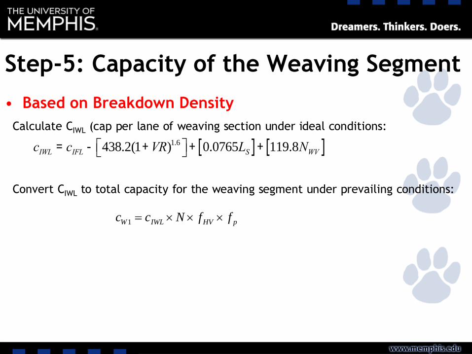
Step-5: Capacity of the Weaving Segment
• Based on Breakdown Density
cIWL = cIFL - 438.2(1+VR)1.6éë ùû+ 0.0765LS[ ]+ 119.8NWV[ ]
Calculate CIWL (cap per lane of weaving section under ideal conditions:
Convert CIWL to total capacity for the weaving segment under prevailing conditions:
pHVIWLW ffNcc 1
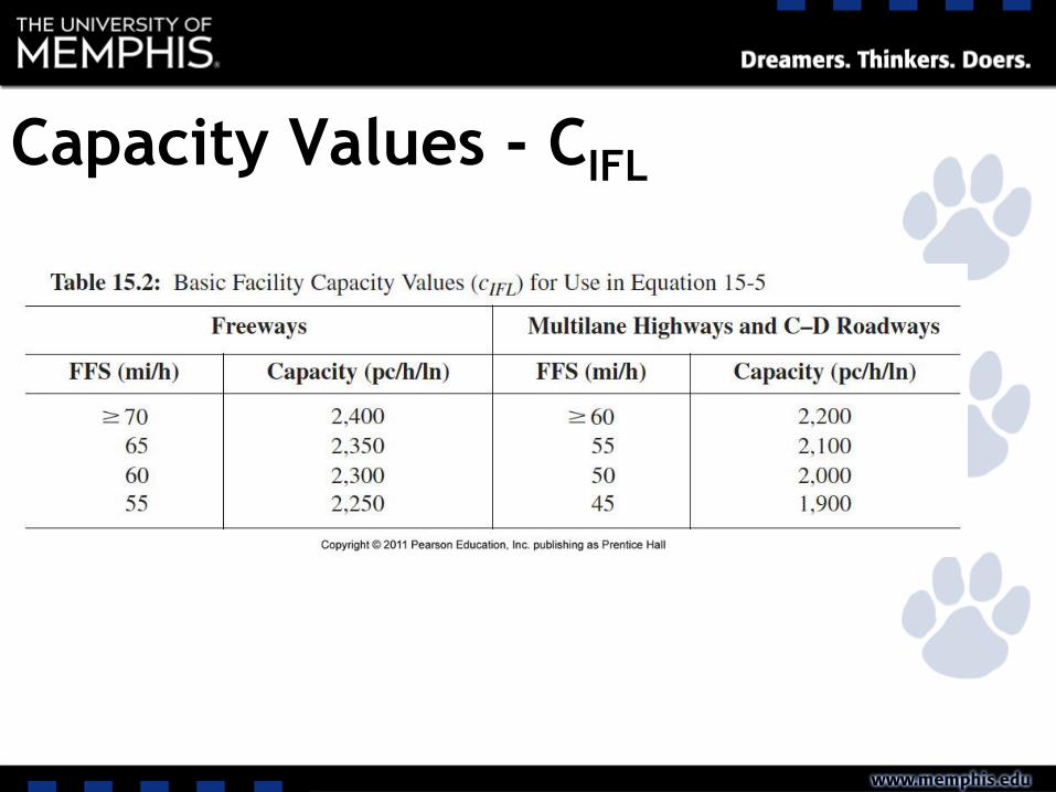
Capacity Values - CIFL
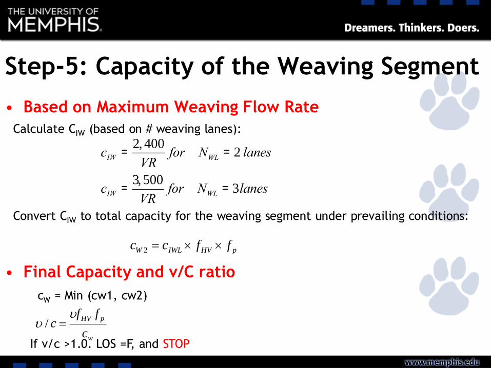
Step-5: Capacity of the Weaving Segment
• Based on Maximum Weaving Flow Rate
• Final Capacity and v/C ratio
cIW =2, 400
VRfor NWL = 2 lanes
cIW =3,500
VRfor NWL = 3lanes
Calculate CIW (based on # weaving lanes):
Convert CIW to total capacity for the weaving segment under prevailing conditions:
pHVIWLW ffcc 2
cW = Min (cw1, cw2)
w
pHV
c
ffc
/
If v/c >1.0. LOS =F, and STOP
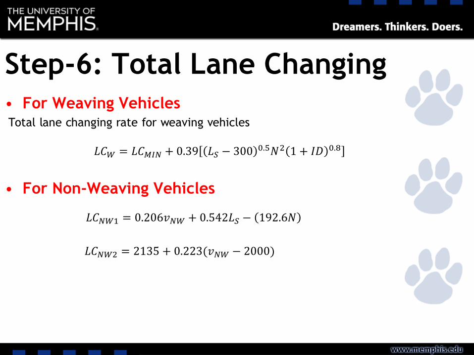
Step-6: Total Lane Changing
• For Weaving VehiclesTotal lane changing rate for weaving vehicles
• For Non-Weaving Vehicles
𝐿𝐶𝑊 = 𝐿𝐶𝑀𝐼𝑁 + 0.39 𝐿𝑆 − 300 0.5𝑁2 1 + 𝐼𝐷 0.8
𝐿𝐶𝑁𝑊1 = 0.206𝑣𝑁𝑊 + 0.542𝐿𝑆 − 192.6𝑁
𝐿𝐶𝑁𝑊2 = 2135 + 0.223(𝑣𝑁𝑊 − 2000)
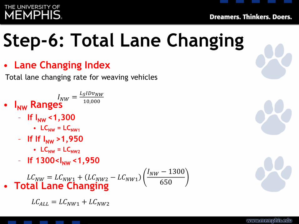
Step-6: Total Lane Changing
• Lane Changing IndexTotal lane changing rate for weaving vehicles
• INW Ranges
– If INW <1,300
• LCNW = LCNW1
– If If INW >1,950
• LCNW = LCNW2
– If 1300<INW <1,950
• Total Lane Changing
𝐼𝑁𝑊 =𝐿𝑆𝐼𝐷𝑣𝑁𝑊
10,000
𝐿𝐶𝑁𝑊 = 𝐿𝐶𝑁𝑊1 + 𝐿𝐶𝑁𝑊2 − 𝐿𝐶𝑁𝑊1
𝐼𝑁𝑊 − 1300
650
𝐿𝐶𝐴𝐿𝐿 = 𝐿𝐶𝑁𝑊1 + 𝐿𝐶𝑁𝑊2
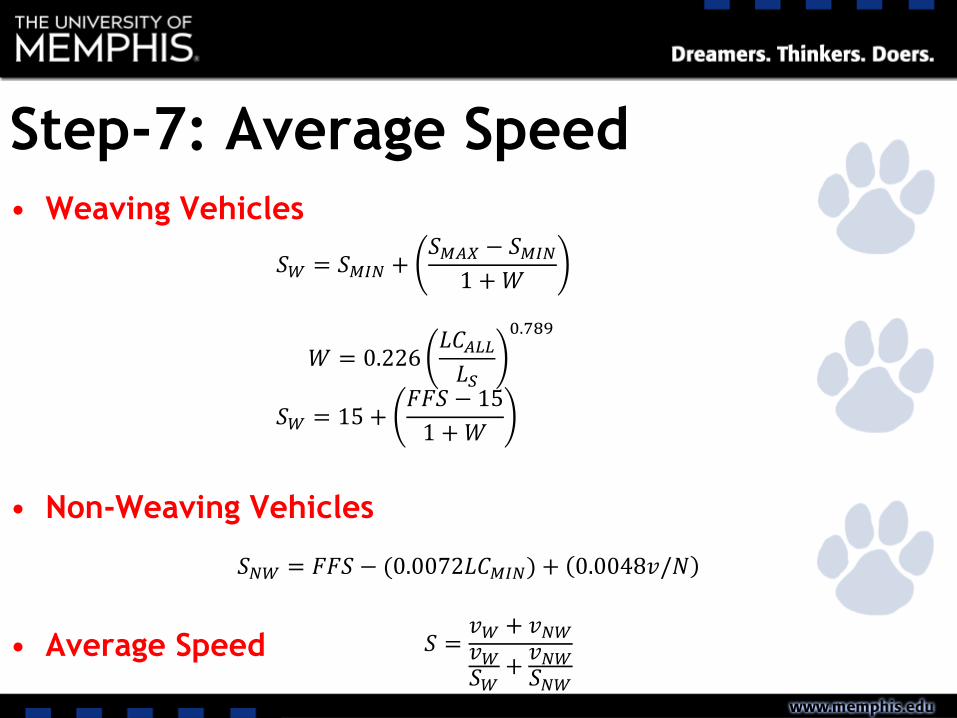
Step-7: Average Speed
• Weaving Vehicles
• Non-Weaving Vehicles
• Average Speed
𝑆𝑊 = 𝑆𝑀𝐼𝑁 +𝑆𝑀𝐴𝑋 − 𝑆𝑀𝐼𝑁
1 +𝑊
𝑊 = 0.226𝐿𝐶𝐴𝐿𝐿𝐿𝑆
0.789
𝑆𝑊 = 15 +𝐹𝐹𝑆 − 15
1 +𝑊
𝑆𝑁𝑊 = 𝐹𝐹𝑆 − (0.0072𝐿𝐶𝑀𝐼𝑁) + 0.0048𝑣/𝑁
𝑆 =𝑣𝑊 + 𝑣𝑁𝑊𝑣𝑊𝑆𝑊
+𝑣𝑁𝑊𝑆𝑁𝑊

Step-8: Determine Density
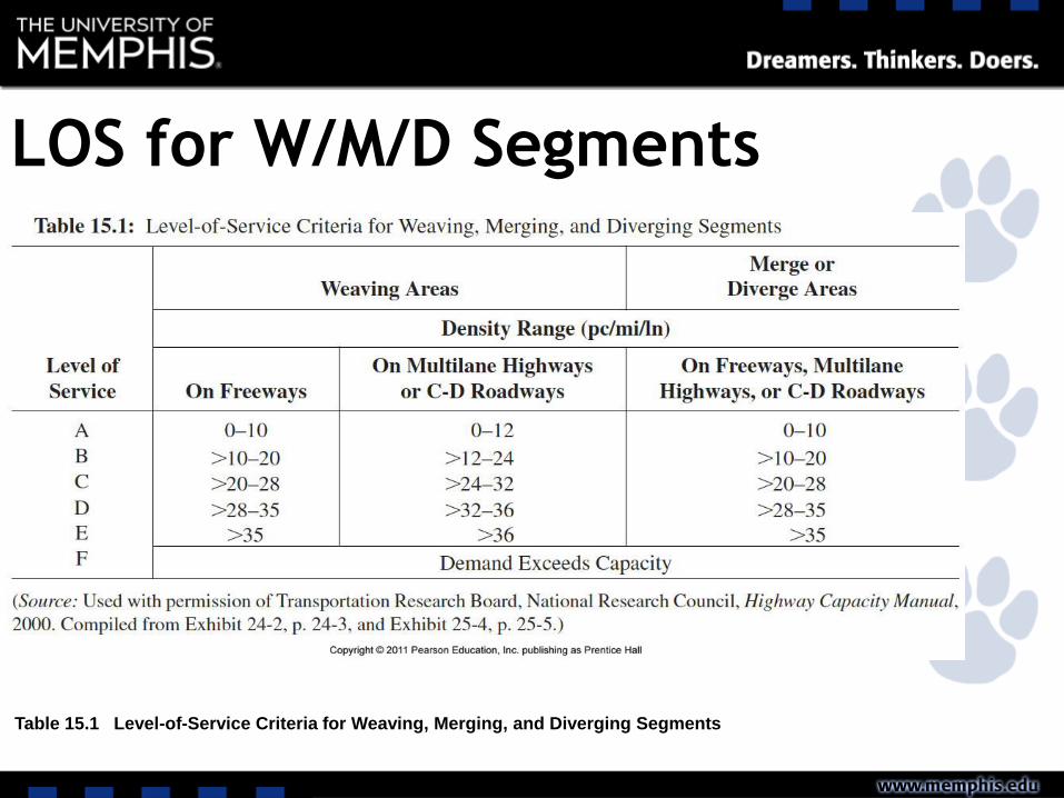
LOS for W/M/D Segments
• Based on density
Table 15.1 Level-of-Service Criteria for Weaving, Merging, and Diverging Segments
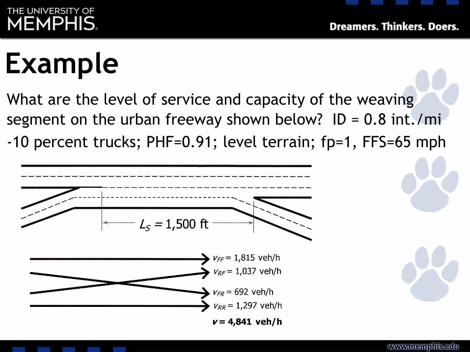
ExampleWhat are the level of service and capacity of the weaving
segment on the urban freeway shown below? ID = 0.8 int./mi
-10 percent trucks; PHF=0.91; level terrain; fp=1, FFS=65 mph
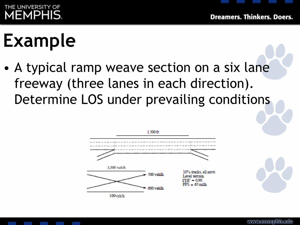
Example
• A typical ramp weave section on a six lane
freeway (three lanes in each direction).
Determine LOS under prevailing conditions