8/19/2010 1 Morning Session Introduction of the new Indiana Roundabout Design Guide IDM Chapter 51.12 American Structurepoint, Inc • Jeromy Grenard, PE, PTOE • Craig Parks, PE DLZ Indiana, LLC • Wes Butch • Haseeb Ghumman, PE, PTOE Presenters

Welcome message from author
This document is posted to help you gain knowledge. Please leave a comment to let me know what you think about it! Share it to your friends and learn new things together.
Transcript
8/19/2010
1
Morning Session
Introduction of the new Indiana Roundabout Design GuideIDM Chapter 51.12
American Structurepoint, Inc
• Jeromy Grenard, PE, PTOE
• Craig Parks, PE
DLZ Indiana, LLC
• Wes Butch
• Haseeb Ghumman, PE, PTOE
Presenters
8/19/2010
2
Introduction51‐12.01
• Guidance for designers & reviewers, not standards
• Based on design principles
• Degree of flexibility for some issues
• Supplement to the FHWA Roundabout Guide
• Written for INDOT staff/consultants
Introduction
8/19/2010
3
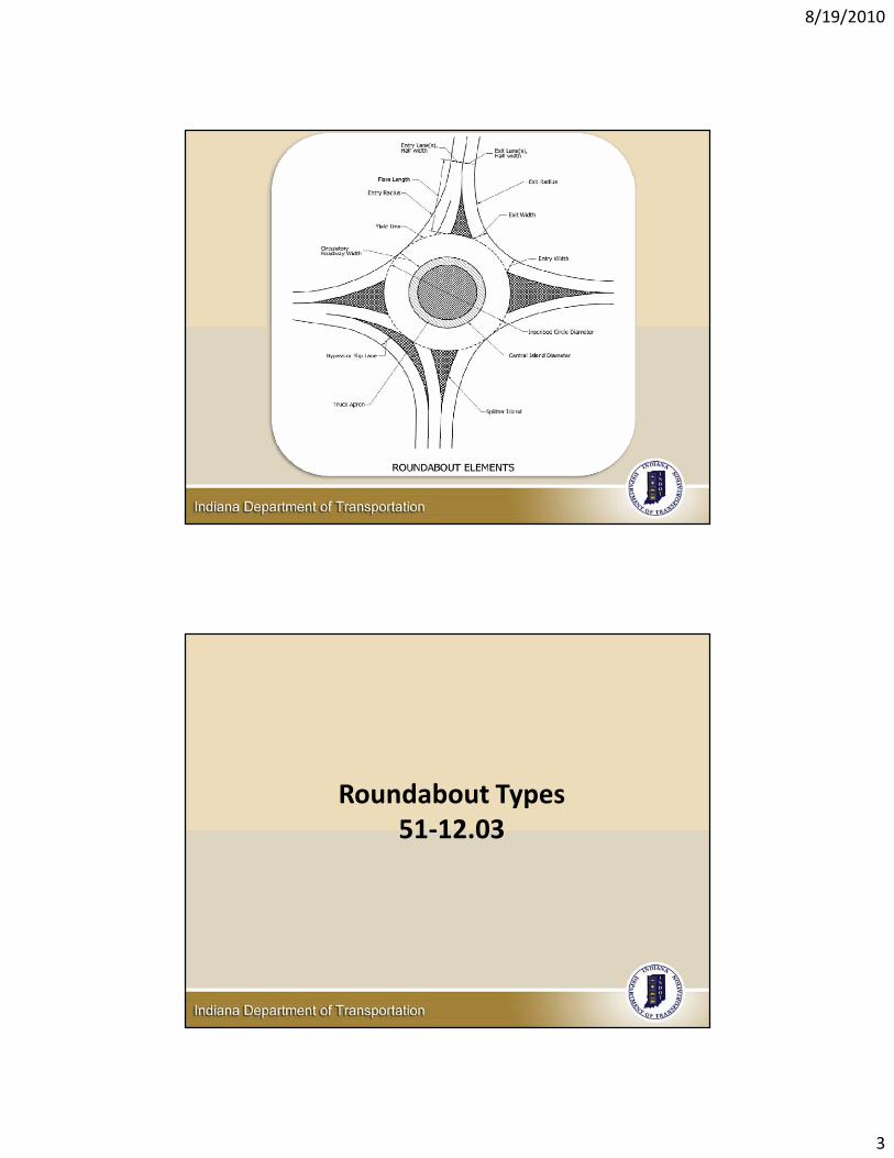
Roundabout Types51‐12.03
8/19/2010
4
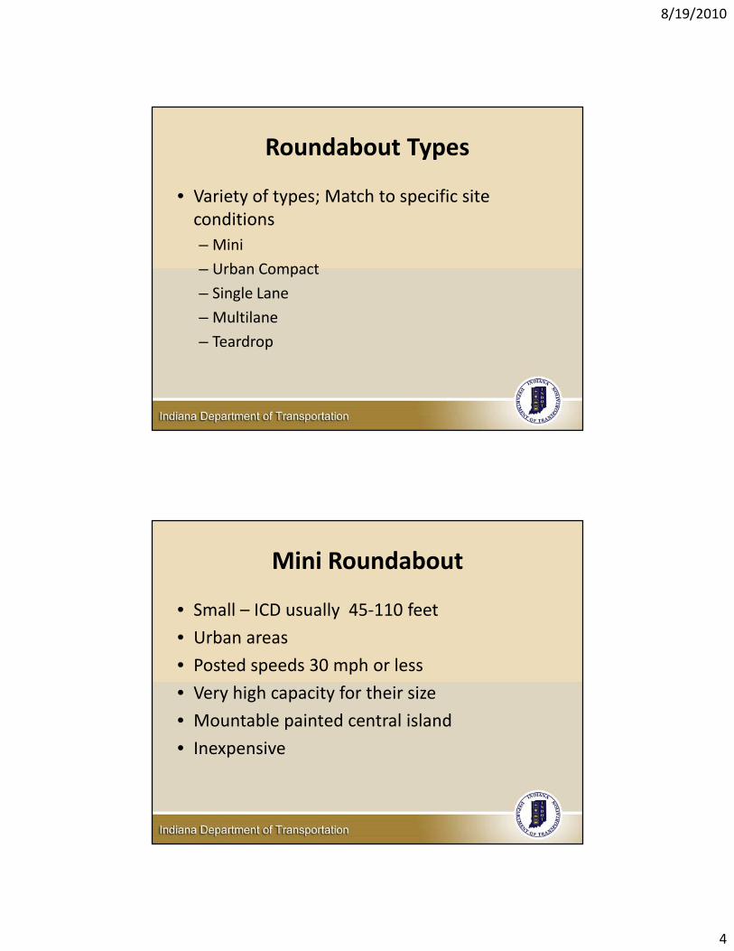
Roundabout Types
• Variety of types; Match to specific site conditions– Mini
– Urban Compact
– Single Lane
– Multilane
– Teardrop
Mini Roundabout
• Small – ICD usually 45‐110 feet
• Urban areas
• Posted speeds 30 mph or less
• Very high capacity for their size
• Mountable painted central island
• Inexpensive
8/19/2010
5
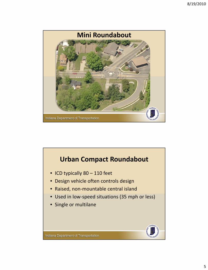
Mini Roundabout
Urban Compact Roundabout
• ICD typically 80 – 110 feet
• Design vehicle often controls design
• Raised, non‐mountable central island
• Used in low‐speed situations (35 mph or less)
• Single or multilane
8/19/2010
6
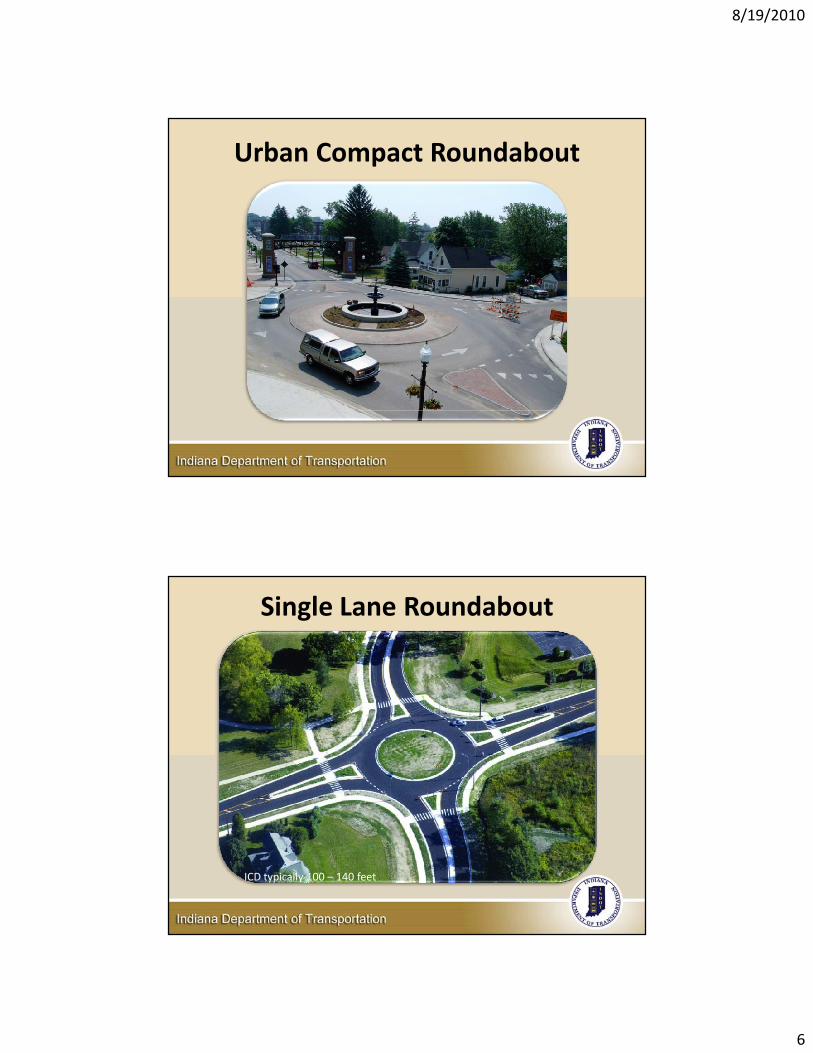
Urban Compact Roundabout
Single Lane Roundabout
ICD typically 100 – 140 feet
8/19/2010
7
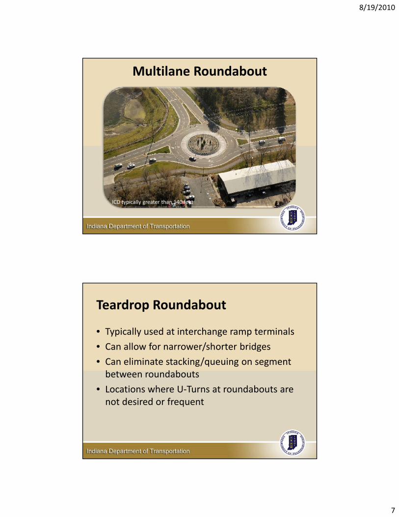
Multilane Roundabout
ICD typically greater than 140 feet
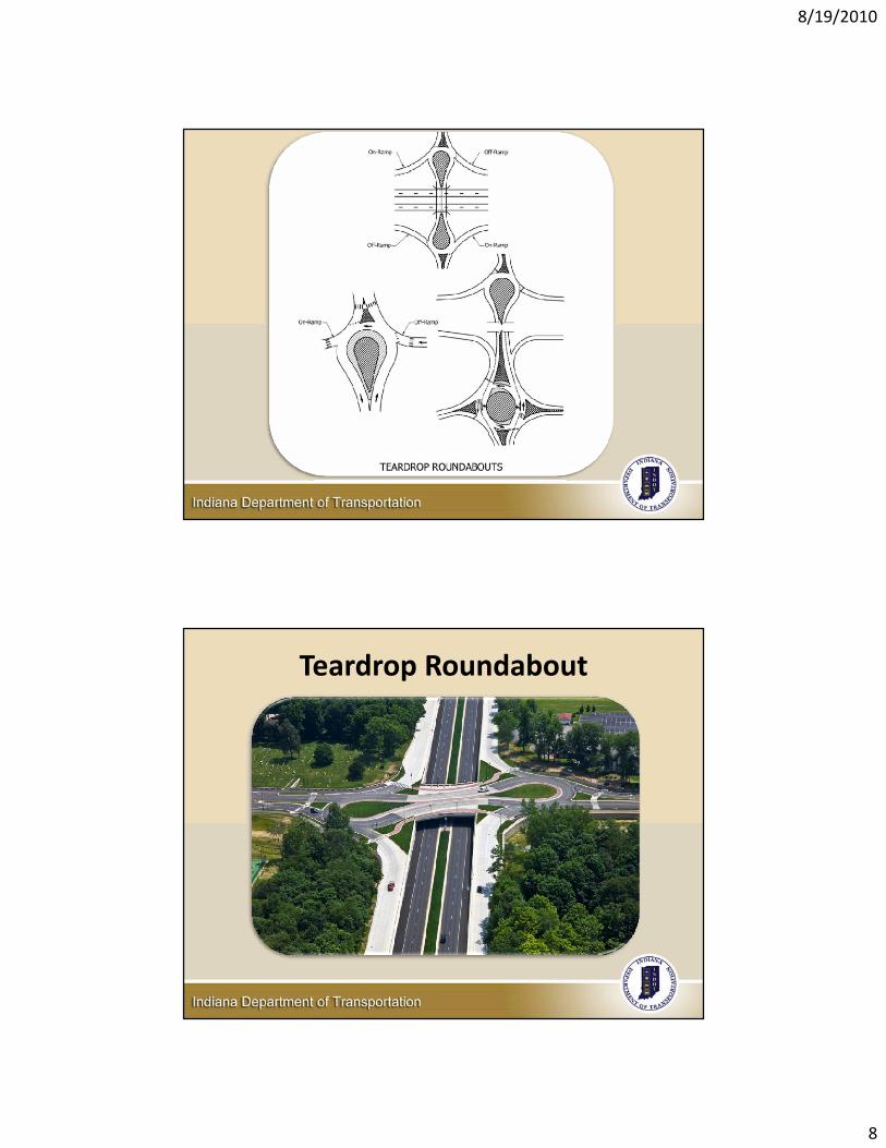
Teardrop Roundabout
• Typically used at interchange ramp terminals
• Can allow for narrower/shorter bridges
• Can eliminate stacking/queuing on segment between roundabouts
• Locations where U‐Turns at roundabouts are not desired or frequent
8/19/2010
8
Teardrop Roundabout
8/19/2010
9
Planning51‐12.04
Planning Process
• Roundabout should be considered as one option in INDOT studies/designs
Data Collection20‐year traffic projectionsCapacity analysisRoundabout concept designPublic involvementCompare to other intersection typesSelect preferred option
8/19/2010
10
Typical Data Needs• INDOT‐approved design‐year peak hour turning
movement projections (AM/PM)• Major off‐peak traffic generators• Design vehicle • Electronic file of survey/aerial photo• Right‐of‐way (ROW)• Crash data (3 years), if available• Traffic control for nearby intersections• Major constraints near intersection• Existing and future planned non‐motorized facilities• Truck percentages• Accommodation of disabled persons
Evaluation Criteria• Safety• Capacity• Traffic operations• Cost• Design life• ROW impacts• Ped/bike accommodations• Aesthetics• Interaction with nearby intersections• Drives/access management• Public input• Constructability• Traffic maintenance• Social, economic, environmental impacts

8/19/2010
11
Beneficial Locations & Applications
• High‐speed rural intersections• Intersections with crash histories• Intersections with traffic operational problems• Closely spaced intersections• Intersections near structures• Freeway interchanges• As a part of an access management program• Intersections with unusual geometry • Gateway entry points• Community enhancements• Near schools
High Speed Rural ‐ Kansas• 65 mph all approaches
• Before (2‐way stop)
– 25 inj crashes in 5 years
• After (roundabout)
– 3 PDO crashes in first 36 months
– No inj crashes, no fatalities
8/19/2010
12
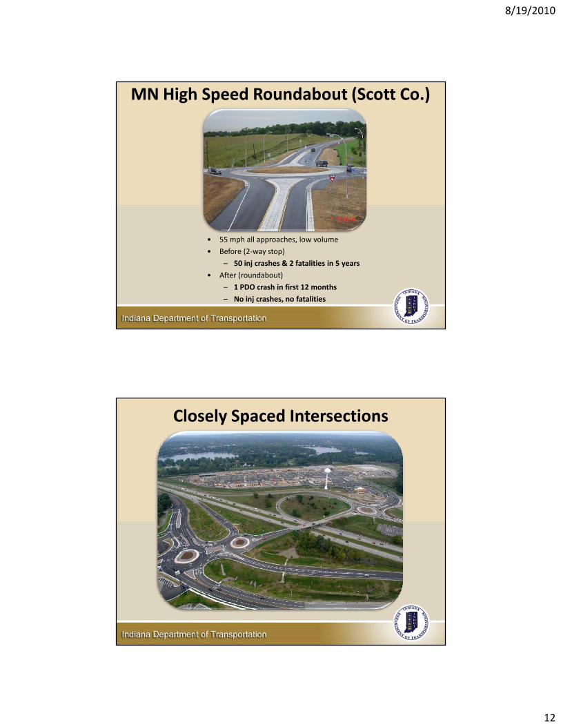
MN High Speed Roundabout (Scott Co.)
• 55 mph all approaches, low volume
• Before (2‐way stop)
– 50 inj crashes & 2 fatalities in 5 years
• After (roundabout)
– 1 PDO crash in first 12 months
– No inj crashes, no fatalities
Closely Spaced Intersections
8/19/2010
13
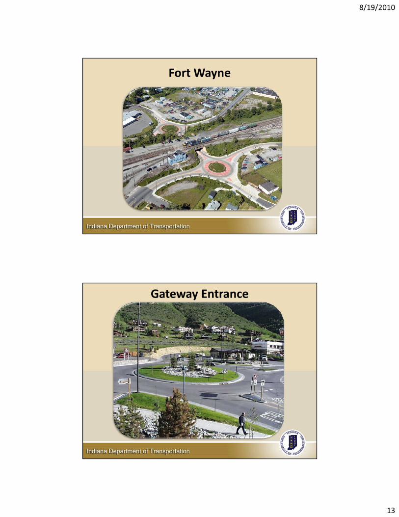
Fort Wayne
Gateway Entrance
8/19/2010
14
Locations and Applications Where Care Should Be Exercised
• Intersections within a system of coordinated signals
• Intersections with steep grade
• Intersections where stopping sight distance cannot be achieved
• Intersections near railroad crossings
• Closely spaced intersections
Roundabout Operation51‐12.05
8/19/2010
15
Operations
• Dependent upon geometric design and driver behavior
• Geometry intended to slow drivers
• Properly designed, drivers do not switch lanes or weave in a multi‐lane roundabout
Operational Analysis Tools
• Several tools available for analyzing capacity of a roundabout
• INDOT not mandating use of a particular software
• Macro models: RODEL, aaSIDRA, ARCADY, etc.
• Micro‐simulation models: VISSIM, PARAMICS, etc.
8/19/2010
16
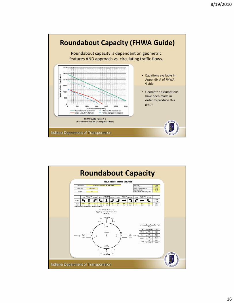
Roundabout Capacity (FHWA Guide)Roundabout capacity is dependant on geometric features AND approach vs. circulating traffic flows.
FHWA Guide Figure 4‐6 (based on extensive UK empirical data)
• Equations available in Appendix A of FHWA Guide.
• Geometric assumptions have been made in order to produce this graph
Roundabout Capacity
8/19/2010
17
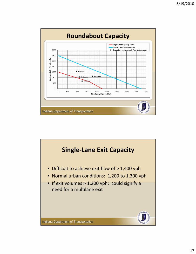
Roundabout Capacity
Single‐Lane Exit Capacity
• Difficult to achieve exit flow of > 1,400 vph
• Normal urban conditions: 1,200 to 1,300 vph
• If exit volumes > 1,200 vph: could signify a need for a multilane exit

8/19/2010
18
Truck Effects on Capacity
FHWA Guide Exhibit 4‐1
Pedestrian Effects on CapacitySingle Lane
FHWA Guide Exhibit 4‐7
8/19/2010
19
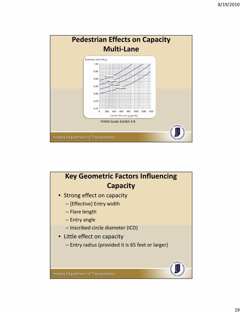
Pedestrian Effects on CapacityMulti‐Lane
FHWA Guide Exhibit 4‐8
Key Geometric Factors Influencing Capacity
• Strong effect on capacity– [Effective] Entry width
– Flare length
– Entry angle
– Inscribed circle diameter (ICD)
• Little effect on capacity– Entry radius (provided it is 65 feet or larger)
8/19/2010
20
Key Factors Influencing Capacity• Lane use balance
– Designer should strive for lane use balance on each approach
– If lane balance not possible, capacity analysis should be performed on a lane‐by‐lane basis
• Right turn bypass lane– Use of right turn bypass lane can increase capacity if there are a high percentage of right turning vehicles
– Use caution if a pedestrian crossing is present
Roundabout Safety51‐12.06
8/19/2010
21
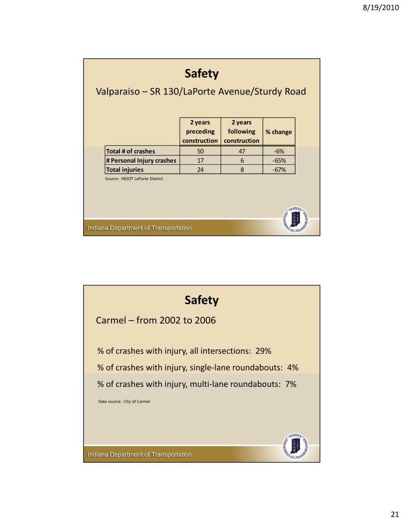
SafetyValparaiso – SR 130/LaPorte Avenue/Sturdy Road
2 years preceding
construction
2 years following
construction% change
Total # of crashes 50 47 ‐6%# Personal Injury crashes 17 6 ‐65%Total injuries 24 8 ‐67%Source: INDOT LaPorte District
Safety
Carmel – from 2002 to 2006
Data source: City of Carmel
% of crashes with injury, all intersections: 29%
% of crashes with injury, single‐lane roundabouts: 4%
% of crashes with injury, multi‐lane roundabouts: 7%
8/19/2010
22
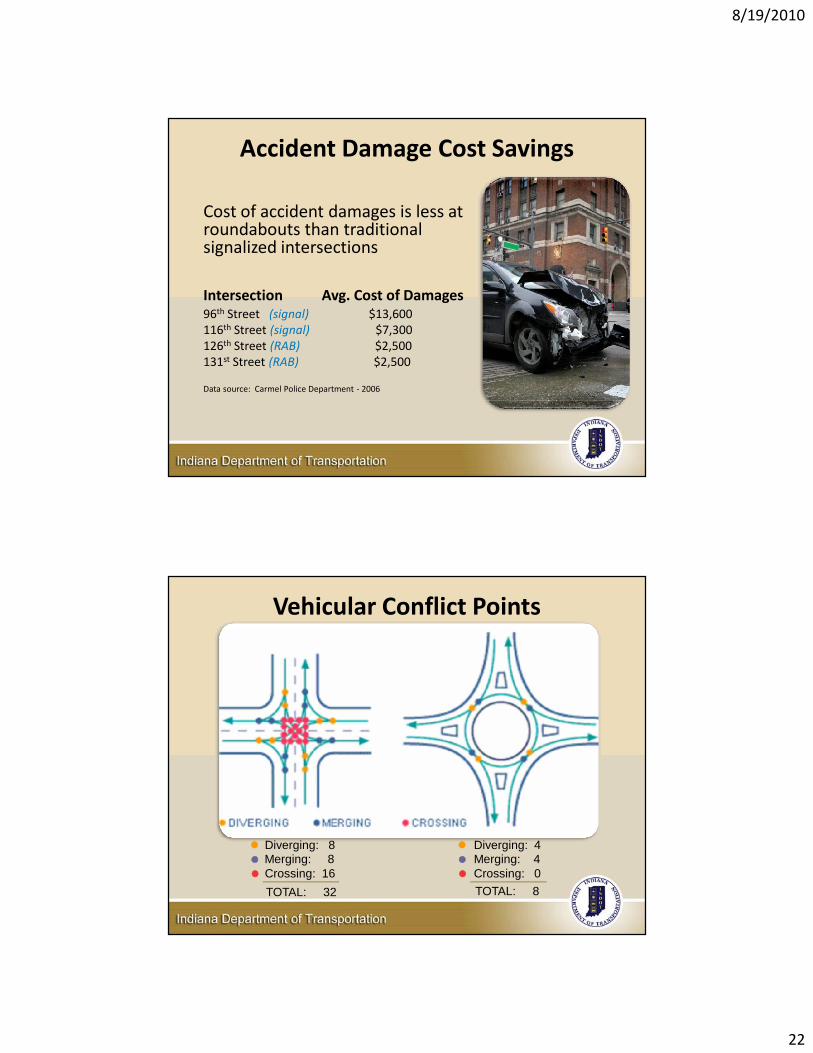
Accident Damage Cost Savings
Cost of accident damages is less at roundabouts than traditional signalized intersections
Intersection Avg. Cost of Damages96th Street (signal) $13,600116th Street (signal) $7,300126th Street (RAB) $2,500131st Street (RAB) $2,500
Data source: Carmel Police Department ‐ 2006
Vehicular Conflict Points
Diverging: 8Merging: 8Crossing: 16
Diverging: 4Merging: 4Crossing: 0
TOTAL: 32 TOTAL: 8
8/19/2010
23
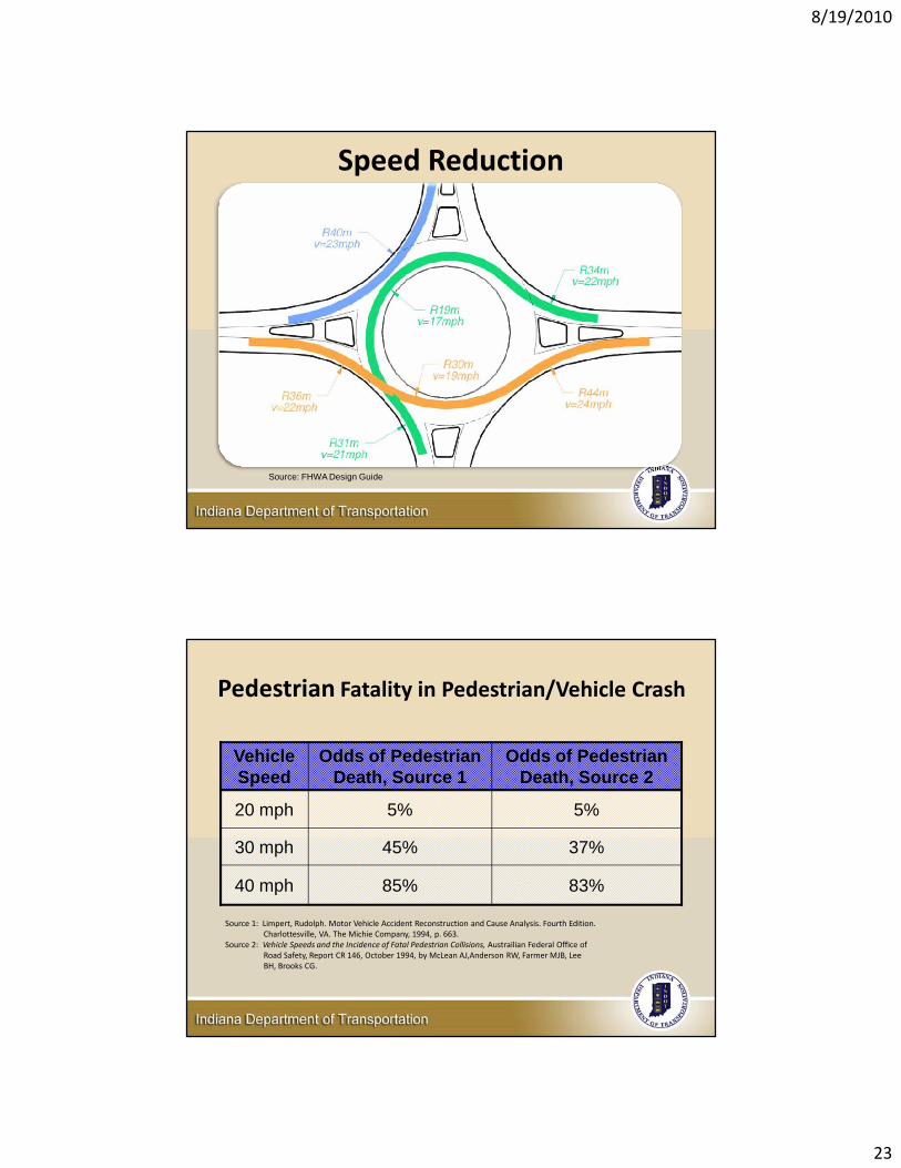
Speed Reduction
Source: FHWA Design Guide
Pedestrian Fatality in Pedestrian/Vehicle Crash
Vehicle Speed
Odds of Pedestrian Death, Source 1
Odds of Pedestrian Death, Source 2
20 mph 5% 5%
30 mph 45% 37%
40 mph 85% 83%
Source 1: Limpert, Rudolph. Motor Vehicle Accident Reconstruction and Cause Analysis. Fourth Edition. Charlottesville, VA. The Michie Company, 1994, p. 663.
Source 2: Vehicle Speeds and the Incidence of Fatal Pedestrian Collisions, Austrailian Federal Office of Road Safety, Report CR 146, October 1994, by McLean AJ,Anderson RW, Farmer MJB, Lee BH, Brooks CG.
8/19/2010
24
Geometric Principles That Maximize Safety
1. Minimize– Entry widths– Circulatory roadway width– Inscribed circle diameter (ICD)– Number of lanes
2. Entry and exit radii– Entry radii not too large or small– Exit radii not too small
3. Speeds appropriate for roundabout type
Geometric Principles That Maximize Safety
4. Entry angle between 20 and 30 degrees
5. To increase capacity, it is preferable to increase flare length than to increase entry width
6. Maximize angle between adjacent legs
7. Avoid entry and exit path overlap
8/19/2010
25
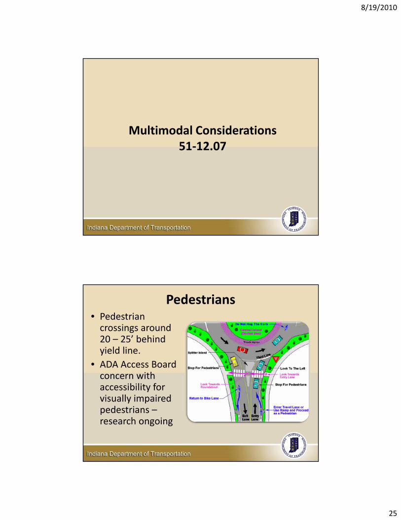
Multimodal Considerations51‐12.07
Pedestrians• Pedestrian crossings around 20 – 25’ behind yield line.
• ADA Access Board concern with accessibility for visually impaired pedestrians –research ongoing
8/19/2010
26
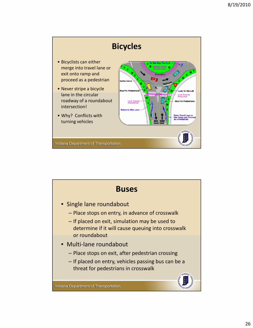
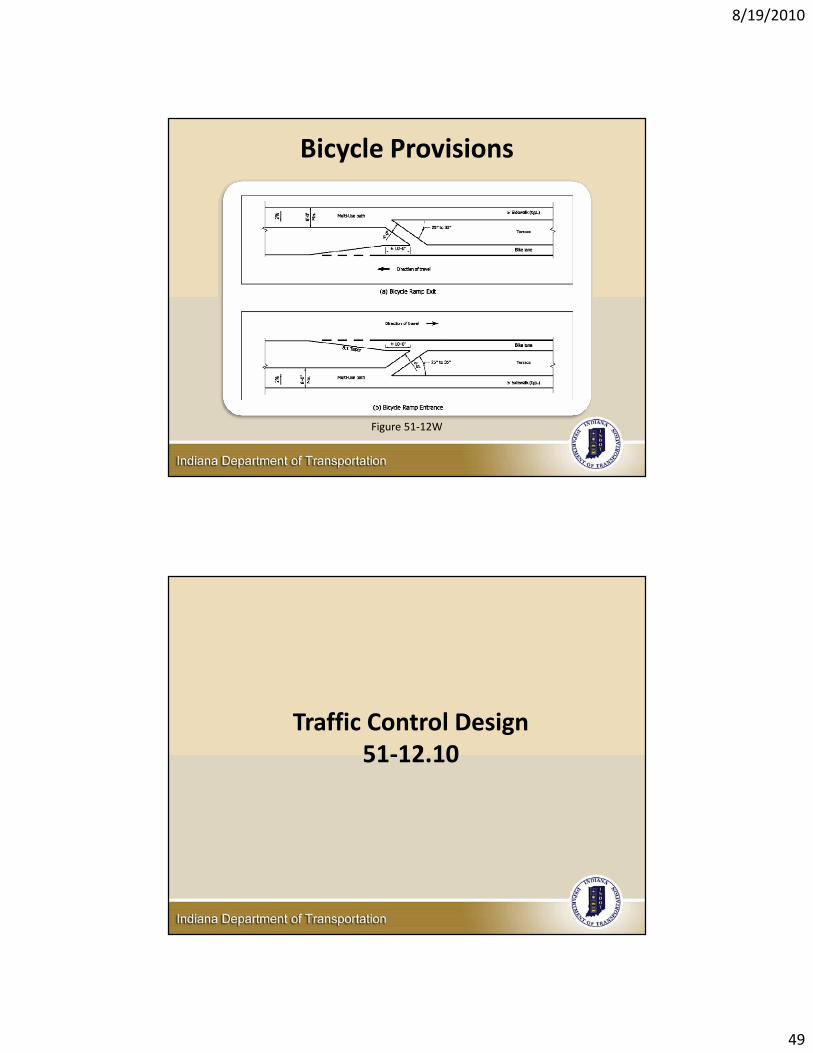
Bicycles
• Bicyclists can either merge into travel lane or exit onto ramp and proceed as a pedestrian
• Never stripe a bicycle lane in the circular roadway of a roundabout intersection!
• Why? Conflicts with turning vehicles
Buses
• Single lane roundabout– Place stops on entry, in advance of crosswalk
– If placed on exit, simulation may be used to determine if it will cause queuing into crosswalk or roundabout
• Multi‐lane roundabout– Place stops on exit, after pedestrian crossing
– If placed on entry, vehicles passing bus can be a threat for pedestrians in crosswalk
8/19/2010
27
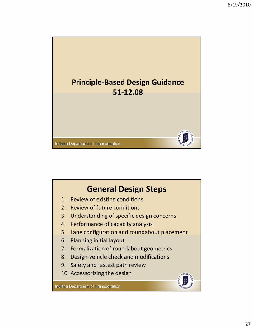
Principle‐Based Design Guidance51‐12.08
General Design Steps1. Review of existing conditions2. Review of future conditions3. Understanding of specific design concerns4. Performance of capacity analysis5. Lane configuration and roundabout placement6. Planning initial layout7. Formalization of roundabout geometrics8. Design‐vehicle check and modifications9. Safety and fastest path review10. Accessorizing the design
8/19/2010
28
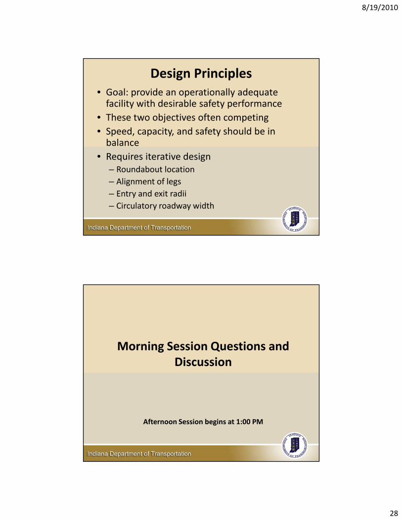
Design Principles• Goal: provide an operationally adequate facility with desirable safety performance
• These two objectives often competing• Speed, capacity, and safety should be in balance
• Requires iterative design– Roundabout location– Alignment of legs– Entry and exit radii– Circulatory roadway width
Morning Session Questions and Discussion
Afternoon Session begins at 1:00 PM
8/19/2010
29
Afternoon Session
Introduction of the new Indiana Roundabout Design GuideIDM Chapter 51.12
Geometric Design51‐12.09
8/19/2010
30
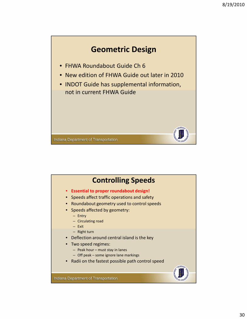
Geometric Design
• FHWA Roundabout Guide Ch 6
• New edition of FHWA Guide out later in 2010
• INDOT Guide has supplemental information, not in current FHWA Guide
Controlling Speeds• Essential to proper roundabout design!• Speeds affect traffic operations and safety• Roundabout geometry used to control speeds• Speeds affected by geometry:
– Entry– Circulating road– Exit– Right turn
• Deflection around central island is the key• Two speed regimes:
– Peak hour – must stay in lanes– Off peak – some ignore lane markings
• Radii on the fastest possible path control speed

8/19/2010
31
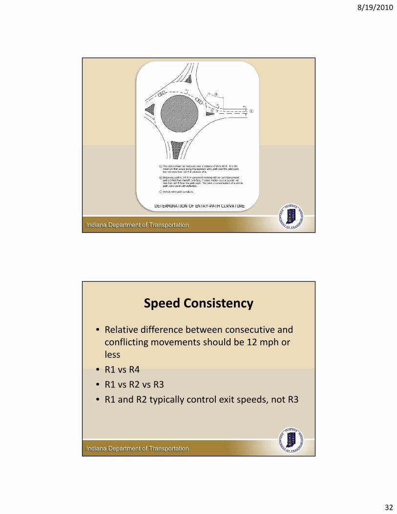
Controlling Speeds
Controlling Speeds• Curvature controls traffic speed• Desire entry path curvature prior to yield line (R1)• Avoid deceleration inside roundabout• Avoid too much deceleration ‐ all the benefits achieved at about 20
mph• Over deceleration of entering traffic:
– Reduces capacity– Causes entry path overlap– Causes approach crashes
• Typically control R1 so it is within 12 mph of R4– Usually minimizes Entry‐Circulating Crashes
• Draw fast path in CAD using spline ‐ detailed instructions in 51‐12.09(03)
• FHWA Guide offsets incorrect:– Use 3’ from painted centerlines, 5’ from curb faces
• On multilane designs, control of R1 must not cause entry path overlap
8/19/2010
32
Speed Consistency
• Relative difference between consecutive and conflicting movements should be 12 mph or less
• R1 vs R4
• R1 vs R2 vs R3
• R1 and R2 typically control exit speeds, not R3
8/19/2010
33
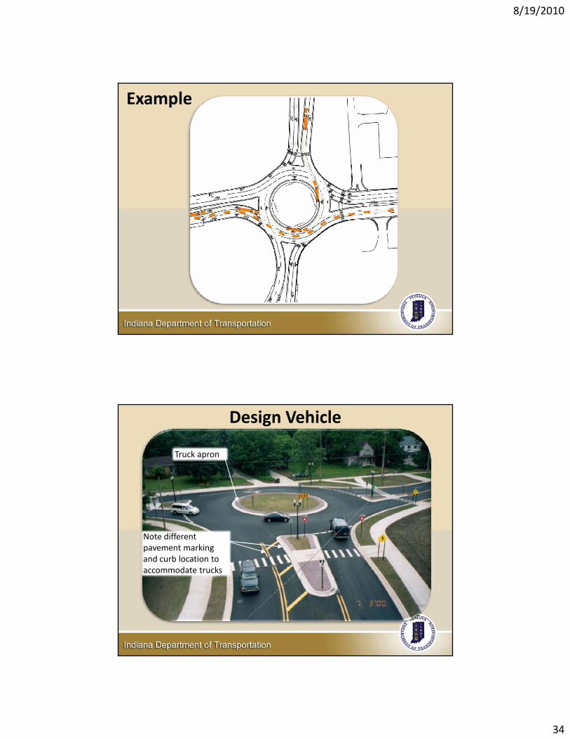
Design Vehicle
• WB‐65 is standard
• Consider farm equipment, permitted loads, etc.
• Truck apron
• ICD/Entry/Circulating/exit widths
• Can control at single lane roundabouts
• Trucks in lane vs. overlapping at multilane roundabouts – debated nationwide
Trucks
• Geometry must accommodate design vehicle
• Use software to view swept path of design vehicle (e.g., Autoturn, Autotrack)
• Adjust geometry if needed
• May lead to different curb and pavement markings on splitter island
8/19/2010
34
Example
Design Vehicle
Truck apron
Note different pavement marking and curb location to accommodate trucks
8/19/2010
35
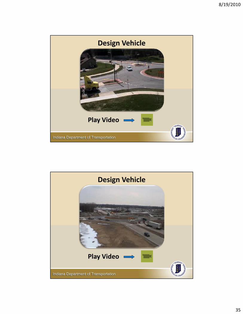
Design Vehicle
Play Video
Design Vehicle
Play Video
8/19/2010
36
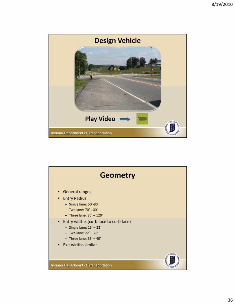
Design Vehicle
Play Video
Geometry
• General ranges
• Entry Radius – Single lane: 50’‐80’
– Two lane: 70’‐100’
– Three lane: 80’ – 120’
• Entry widths (curb face to curb face)– Single lane: 15’ – 22’
– Two lane: 22’ – 28’
– Three lane: 33’ – 40’
• Exit widths similar

8/19/2010
37
Geometry• Circulating widths
– Single lane: 18’ – 25’– Two lane: 30’ – 34’– Three lane: 42’ – 48’
• Splitters– Generally 50’ long– Extend until exit curvature completed– At least 6’ wide at narrowest part of ped xing
• There are exceptions to every one of these!• No substitute for experience and judgment
Inscribed Circle Diameter
• Mini – 40’ to 110’
• Urban compact – 80’ to 110’
• Single lane – 100’ to 140’• Two‐lane – 140’ to 180’
• Three‐lane – 215 ‘ to 275’
• Rural Single or Multilane roundabouts will have larger ICD.
8/19/2010
38
8/19/2010
39
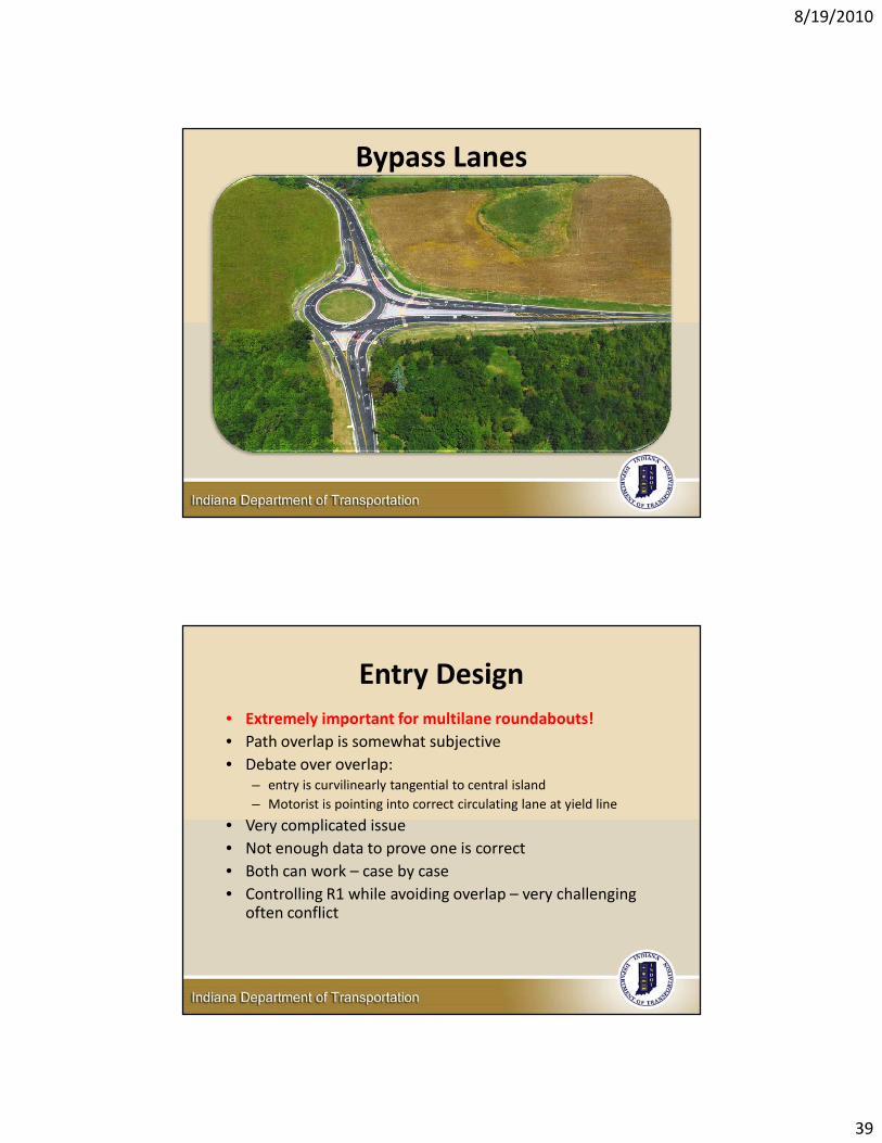
Bypass Lanes
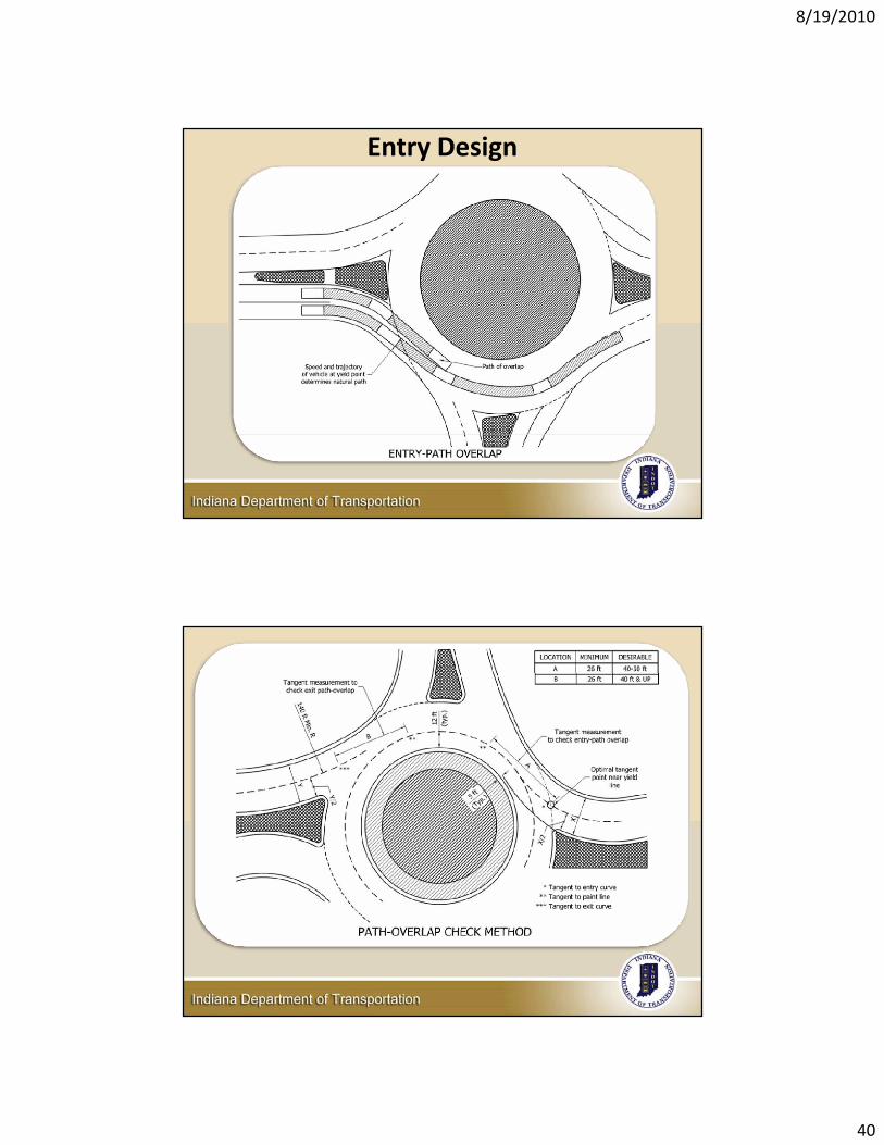
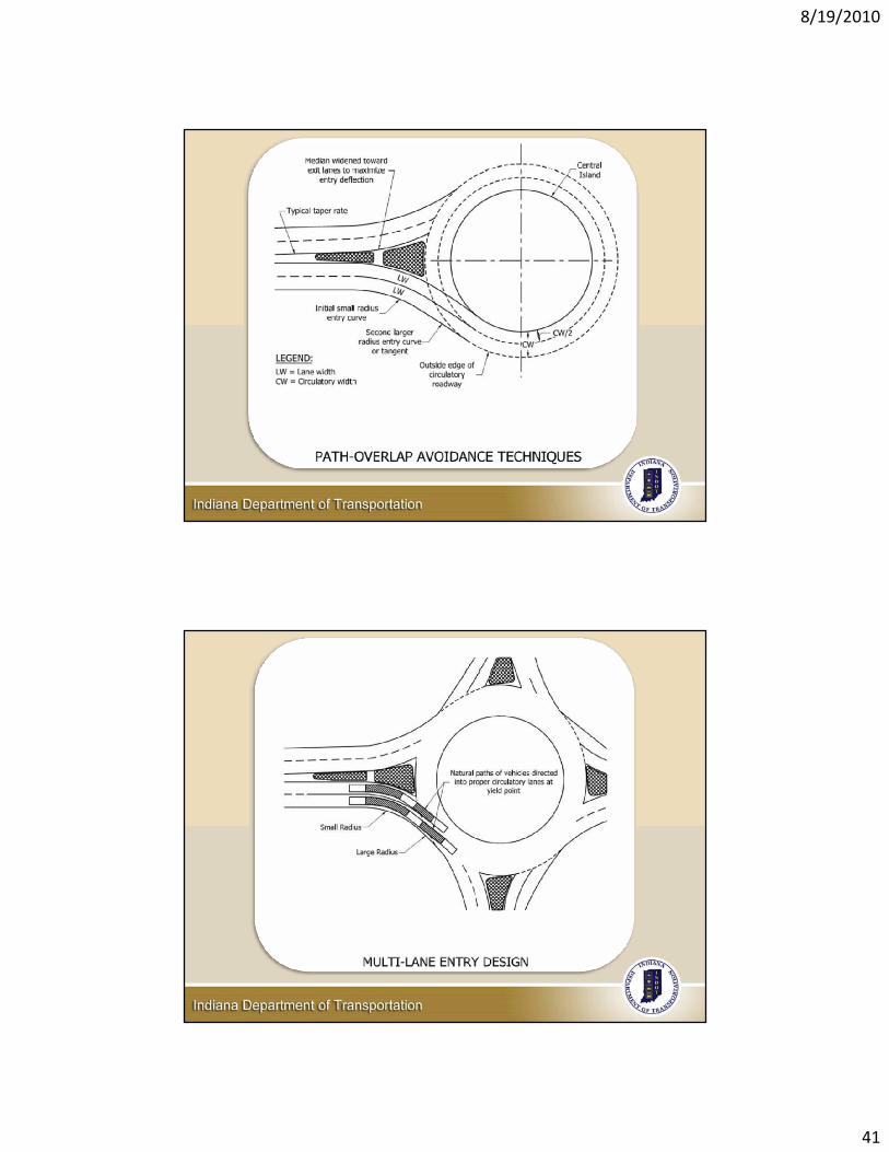
Entry Design• Extremely important for multilane roundabouts!• Path overlap is somewhat subjective• Debate over overlap:
– entry is curvilinearly tangential to central island– Motorist is pointing into correct circulating lane at yield line
• Very complicated issue• Not enough data to prove one is correct• Both can work – case by case• Controlling R1 while avoiding overlap – very challenging
often conflict
8/19/2010
40
Entry Design
8/19/2010
41
8/19/2010
42
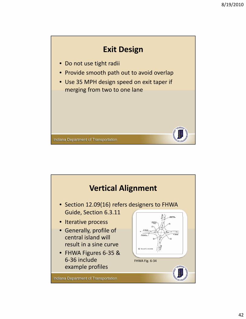
Exit Design
• Do not use tight radii
• Provide smooth path out to avoid overlap
• Use 35 MPH design speed on exit taper if merging from two to one lane
Vertical Alignment
• Section 12.09(16) refers designers to FHWA Guide, Section 6.3.11
FHWA Fig. 6‐34
• Iterative process• Generally, profile of central island will result in a sine curve
• FHWA Figures 6‐35 & 6‐36 include example profiles
8/19/2010
43
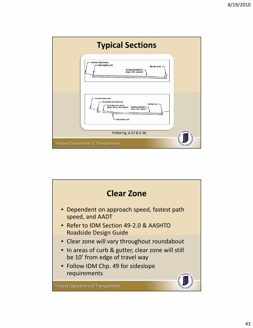
Typical Sections
FHWA Fig. 6‐37 & 6‐38
Clear Zone
• Dependent on approach speed, fastest path speed, and AADT
• Refer to IDM Section 49‐2.0 & AASHTO Roadside Design Guide
• Clear zone will vary throughout roundabout• In areas of curb & gutter, clear zone will still be 10’ from edge of travel way
• Follow IDM Chp. 49 for sidesloperequirements
8/19/2010
44
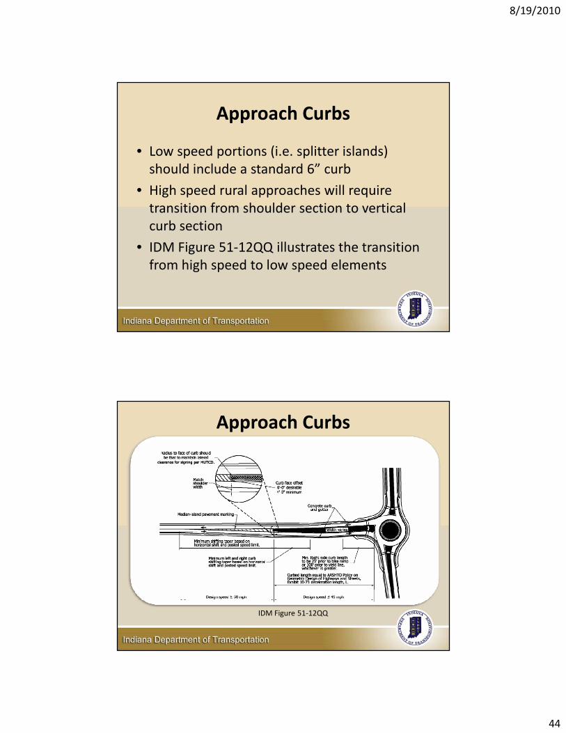
Approach Curbs
• Low speed portions (i.e. splitter islands) should include a standard 6” curb
• High speed rural approaches will require transition from shoulder section to vertical curb section
• IDM Figure 51‐12QQ illustrates the transition from high speed to low speed elements
Approach Curbs
IDM Figure 51‐12QQ
8/19/2010
45
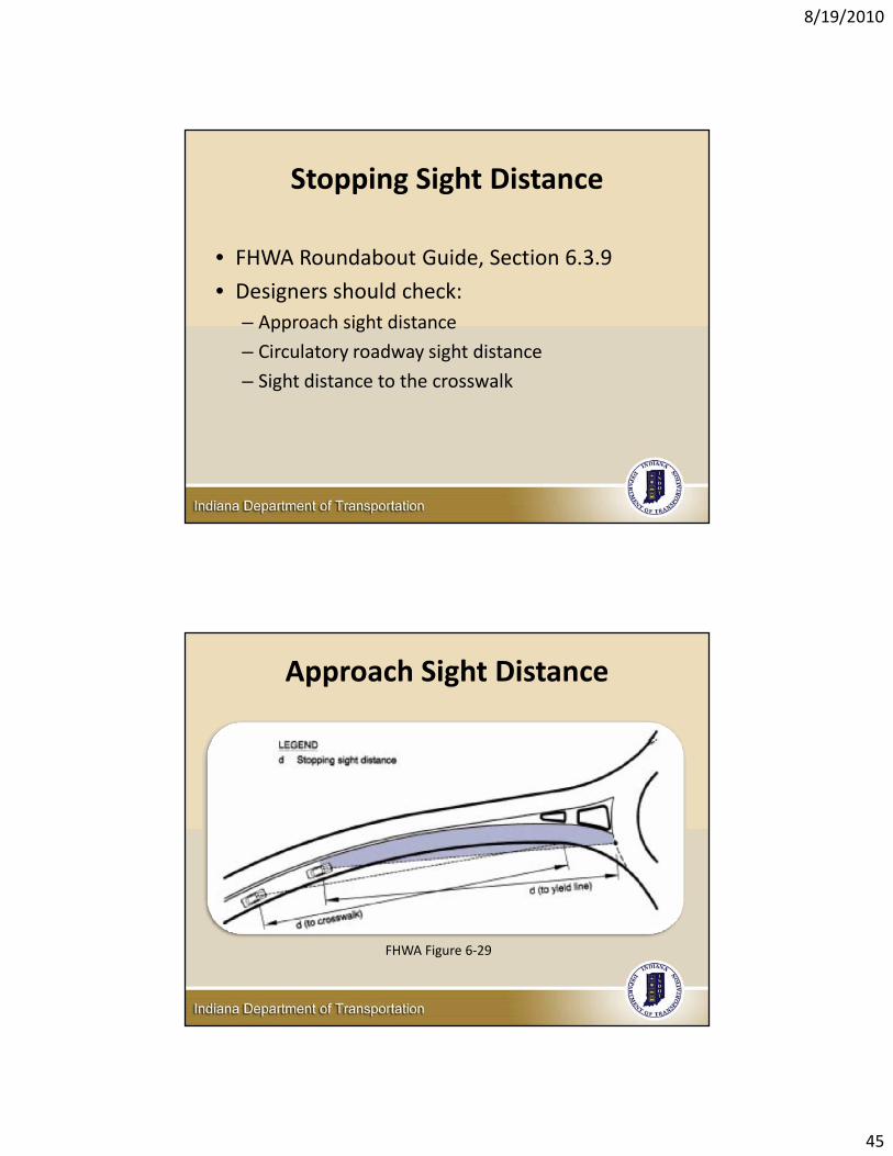
Stopping Sight Distance
• FHWA Roundabout Guide, Section 6.3.9
• Designers should check:– Approach sight distance
– Circulatory roadway sight distance
– Sight distance to the crosswalk
Approach Sight Distance
FHWA Figure 6‐29
8/19/2010
46
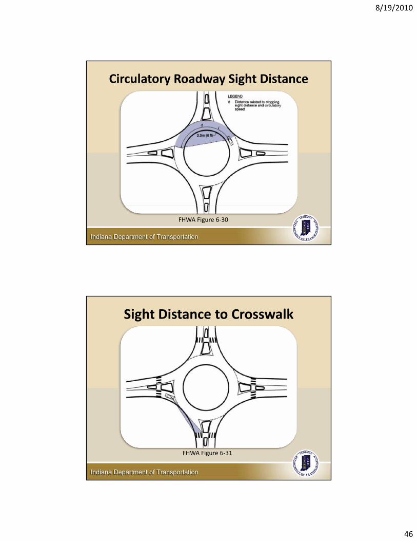
Circulatory Roadway Sight Distance
FHWA Figure 6‐30
Sight Distance to Crosswalk
FHWA Figure 6‐31
8/19/2010
47
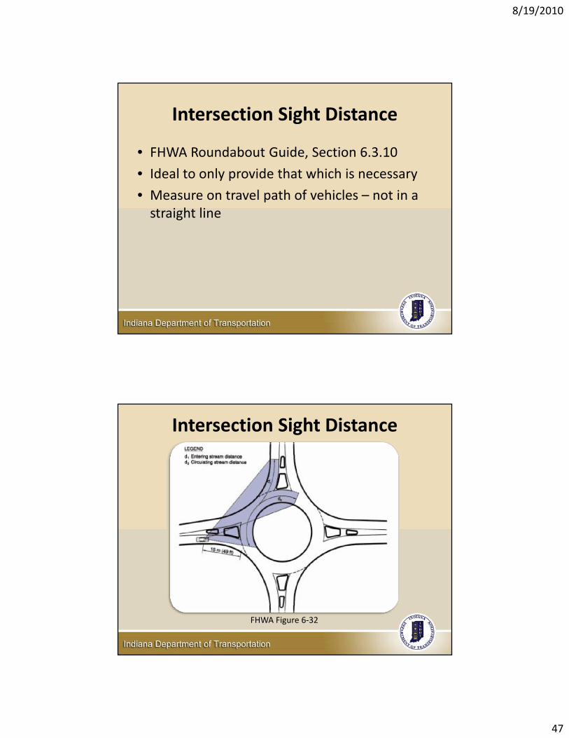
Intersection Sight Distance
• FHWA Roundabout Guide, Section 6.3.10
• Ideal to only provide that which is necessary
• Measure on travel path of vehicles – not in a straight line
Intersection Sight Distance
FHWA Figure 6‐32
8/19/2010
48
Sight Distance
• Restricting visibility at a roundabout can reduce the possibility of a crash– Reduce left visibility until driver is 50’ from yield line
– Raising the central island
• Restrictions should not interfere with approach SSD or ISD
Landscaping Considerations
• Landscaping should be placed to maintain SSD and ISD, but can be placed to purposely reduce sight lines across roundabout
• Draw sight lines to determine areas that can be landscaped
• Refer to FHWA Section 7.5 for additional information on landscaping
8/19/2010
49
Bicycle Provisions
Figure 51‐12W
Traffic Control Design51‐12.10
8/19/2010
50
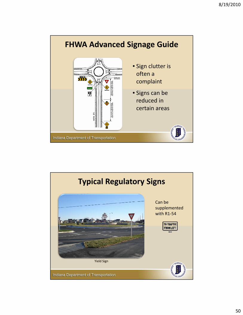
FHWA Advanced Signage Guide
• Sign clutter is often a complaint
• Signs can be reduced in certain areas
Typical Regulatory Signs
Can be supplemented with R1‐54
Yield Sign
8/19/2010
51
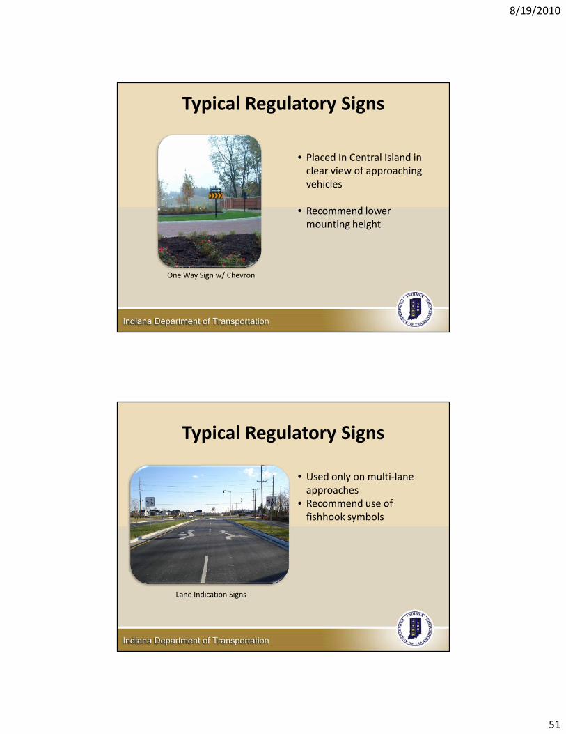
Typical Regulatory Signs
• Placed In Central Island in clear view of approaching vehicles
• Recommend lower mounting height
One Way Sign w/ Chevron
Typical Regulatory Signs
• Used only on multi‐lane approaches
• Recommend use of fishhook symbols
Lane Indication Signs
8/19/2010
52
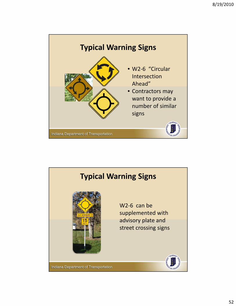
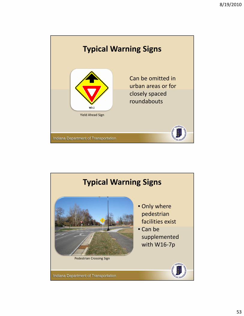
Typical Warning Signs
• W2‐6 “Circular Intersection Ahead”
• Contractors may want to provide a number of similar signs
Typical Warning Signs
W2‐6 can be supplemented with advisory plate and street crossing signs
8/19/2010
53
Typical Warning Signs
Yield Ahead Sign
Can be omitted in urban areas or for closely spaced roundabouts
Typical Warning Signs
Pedestrian Crossing Sign
• Only where pedestrian facilities exist
• Can be supplemented with W16‐7p

8/19/2010
54
Typical Guide Signs
Exit Guide Sign
Placed in splitter island at a 45 degree angle to circulating traffic
Other Signs
Bicycle Sign Assemblies
Intersection Destination & Direction Signs
8/19/2010
55
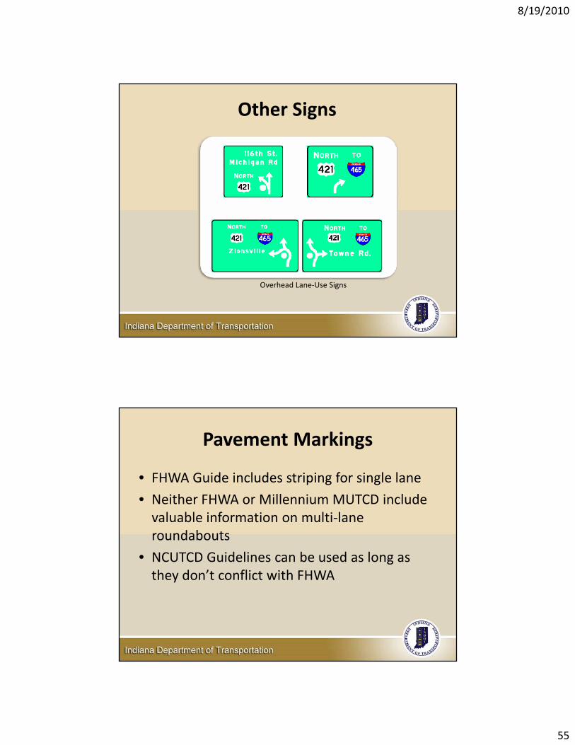
Other Signs
Overhead Lane‐Use Signs
Pavement Markings
• FHWA Guide includes striping for single lane
• Neither FHWA or Millennium MUTCD include valuable information on multi‐lane roundabouts
• NCUTCD Guidelines can be used as long as they don’t conflict with FHWA
8/19/2010
56
Pavement Markings
• Pavement markings should be an integral part of geometric design
• Minimize Lane changes within roundabout
• Should accommodate turning movement volumes
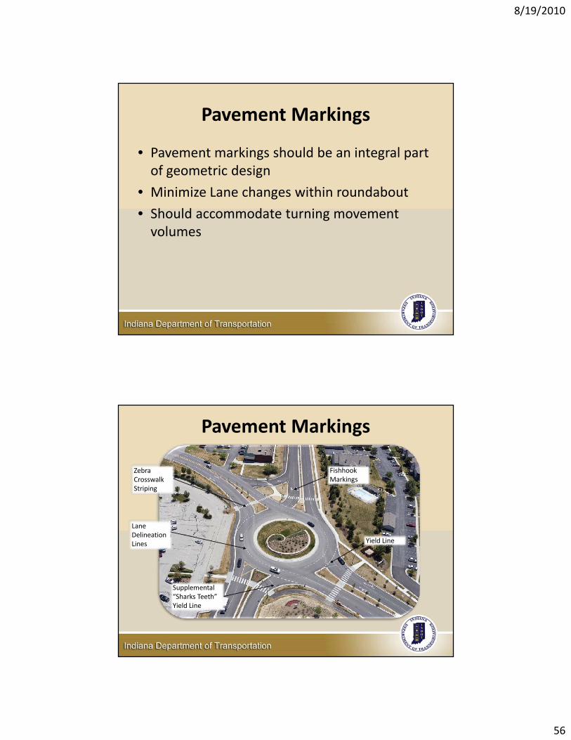
Pavement Markings
Zebra Crosswalk Striping
Supplemental “Sharks Teeth” Yield Line
Lane Delineation Lines Yield Line
Fishhook Markings
8/19/2010
57
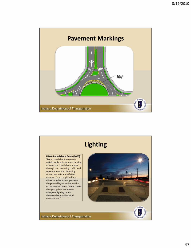
Pavement Markings
Lighting
FHWA Roundabout Guide (2000):“For a roundabout to operate satisfactorily, a driver must be able to enter the roundabout, move through the circulating traffic, and separate from the circulating stream in a safe and efficient manner. To accomplish this, a driver must be able to perceive the general layout and operation of the intersection in time to make the appropriate maneuvers. Adequate lighting should therefore be provided at all roundabouts.”
8/19/2010
58
Lighting
• Present guidance and resources– IDM Chapter 78
– AASHTO (Roadway Lighting Design Guide)
– IESNA (DG‐19‐08)
• Urban areas– Improve visibility of pedestrians and bicyclist
– Be careful not to backlight pedestrians
– Transition speed areas
Where to Consider Lighting
• Urban Areas• Improve visibility of pedestrians and bicyclists• Transition speed areas
• Suburban Areas• One or more approaches are illuminated• Competing non‐roadway illumination• High night time volumes• Pedestrians
• Rural Areas• Retroreflective markings and signs
8/19/2010
59
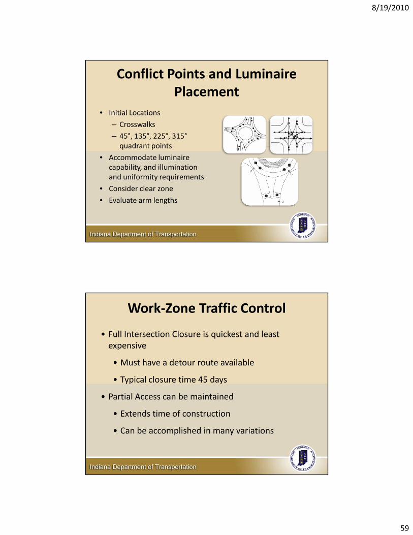
Conflict Points and LuminairePlacement
• Initial Locations
– Crosswalks
– 45°, 135°, 225°, 315°quadrant points
• Accommodate luminaire capability, and illumination and uniformity requirements
• Consider clear zone
• Evaluate arm lengths
Work‐Zone Traffic Control
• Full Intersection Closure is quickest and least expensive
• Must have a detour route available
• Typical closure time 45 days
• Partial Access can be maintained
• Extends time of construction
• Can be accomplished in many variations
8/19/2010
60
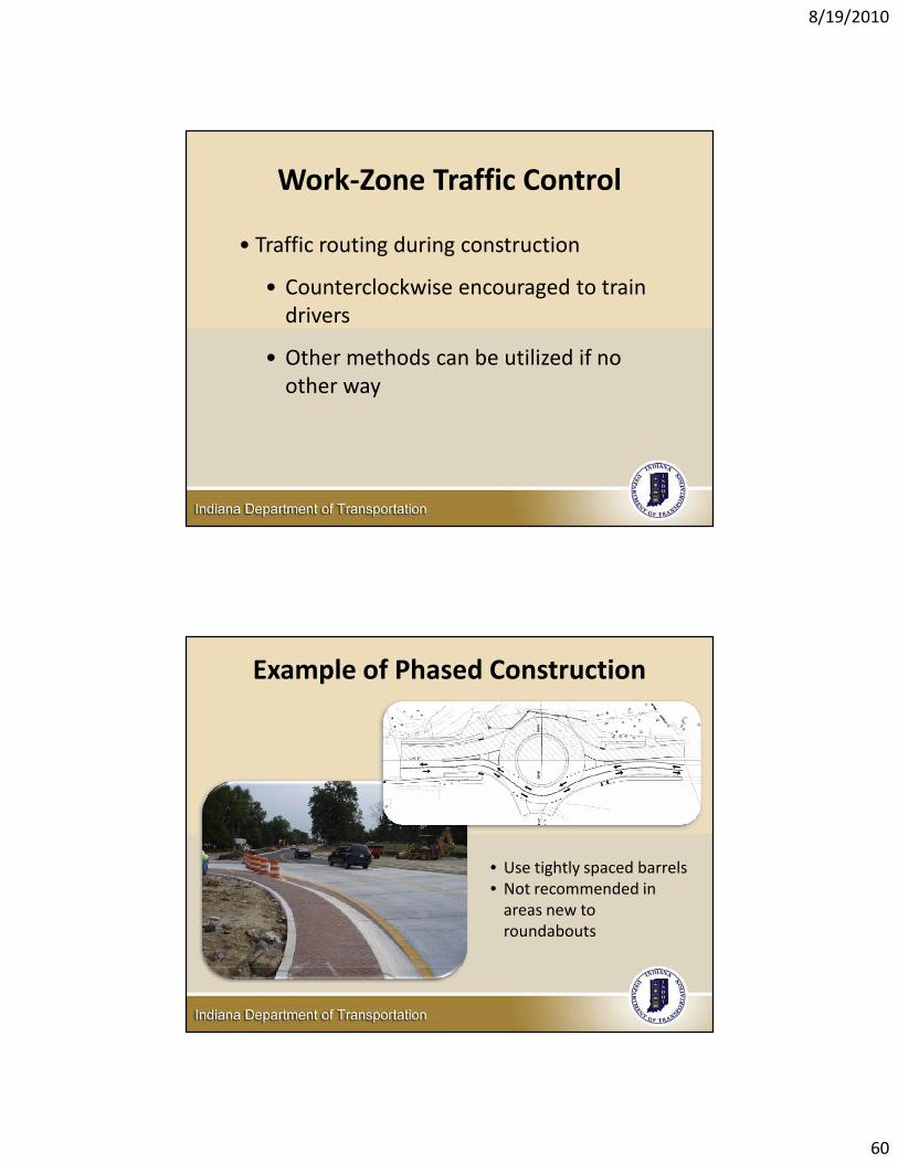
Work‐Zone Traffic Control
• Traffic routing during construction
• Counterclockwise encouraged to train drivers
• Other methods can be utilized if no other way
Example of Phased Construction
• Use tightly spaced barrels• Not recommended in areas new to roundabouts
8/19/2010
61
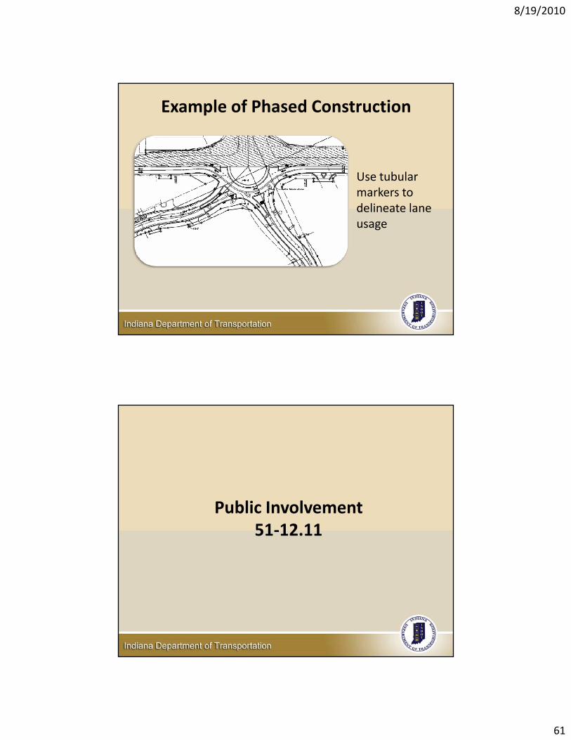
Example of Phased Construction
Use tubular markers to delineate lane usage
Public Involvement51‐12.11
8/19/2010
62
Roundabout Education
• There is no such thing as too much education
• Use safety benefits and data to explain implementation of roundabouts
• Implementation and realized benefits make believers out of naysayers
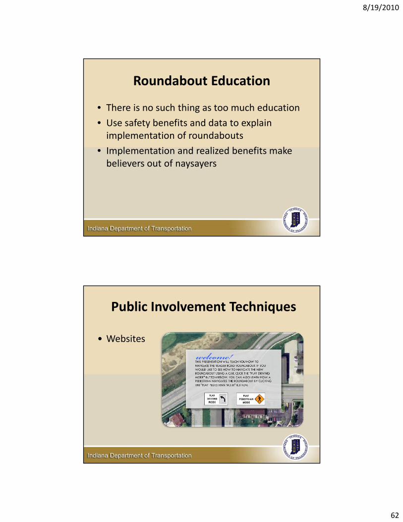
• Websites
Public Involvement Techniques

8/19/2010
63
Public Involvement Techniques
• Websites
• Flyers
• Newspaper Articles
• Presentations
• Drivers Education Programs
Roundabout Education
• Change is hard
• Before installation, up to 80% of public may be opposed to roundabouts
• After installation, approval rating of roundabout is typically 80%
• Be prepared for a learning curve

8/19/2010
64
Afternoon Session Questions and Discussion
Thank you for attending!
Related Documents