International Research Journal of Engineering and Technology (IRJET) e-ISSN: 2395 -0056 Volume: 03 Issue: 03 | Mar-2016 www.irjet.net p-ISSN: 2395-0072 © 2016, IRJET ISO 9001:2008 Certified Journal Page 429 VOLTAGE STABILITY ANALYSIS IN POWER SYSTEM BY OPTIMAL PLACEMENT OF SVC Kalyani zanak 1 , Dr.V.K.Chandrakar 2 , Archana patil 3 1 PG student[IPS],Dept.of EE,GHRCE,Nagpur,India 2 Associate professor,Dept.of EE,GHRCE,Nagpur,India 3 Assistant professor,Dept of EE,GHRCE,Nagpur,India ---------------------------------------------------------------------***--------------------------------------------------------------------- Abstract - Voltage is always the most important part of the power system response and it is an important aspect of system stability and its security. The voltage instability generally results in monotonically decreasing voltages. So that Flexible AC transmission system (FACTS) devices play an important role in improving the performance of the power system, but these devices are very costly and so need to be placed optimally. During a large disturbance improving the systems voltage by upgrading the reactive power handling capacity of the system by using SVC is the area of study. Thus the effect of Static VAR Compensator (SVC) in voltage stability enhancement will be studied in this paper and a technique is based on line stability index, real power performance index and reduction of total system VAR power losses has been intended to decide the optimal location of SVC. Key Words: Voltage stability, FACTS, SVC, IEEE 5 bus system, L- index. 1.INTRODUCTION Today, Electricity demand is increased as number of industries is increasing day by day. As the volume of power transmitted and distributed increases, hence do the requirements for high quality and reliable supply. Thus the Transmission networks of present power systems are becoming progressively more stressed because of increasing requirement and limitations on building new lines. Maintaining system stable and secure operation of a power system is a challenging task. Voltage instability is the One of the major concerns of power system stability. It causes the system voltage collapse, which makes the voltage of system to decrease to a level that is unacceptable. Voltage instability occurs because of lack of reactive power. This problem is reduced by Flexible AC Transmission System (FACTS) devices. FACTS are the power electronics based devices, which can change parameters like impedance, voltage and phase angle. FACTS devices also helps to minimize flows in heavily loaded lines, developing in an increase loadability,low system loss, improved stability of the network, decreased cost of production and satisfied contractual requirement by controlling the power flows in the network. They give control facilities, both in steady state power flow control and dynamic stability control. FACTS devices can be connected to a transmission lines in various ways, such as in series, shunt or a combination of series and shunt. Each one of those has their own characteristics and limitations. 2. STATIC VAR COMPANSATOR (SVC) Static Var Compensator is shunt connected FACTS device. Means it is installed in parallel with a bus. Diagram of SVC is shown in fig.1.1. SVC is made up of mechanically switched reactor, Thyristor controlled reactor (TCR), Thyristor Switched Capacitor (TSC), Harmonic Filter and mechanically switched capacitor. If load is capacitive, TCR consume VARs and lower system voltage. If load is inductive, capacitor banks are switched on to supply VARs and higher system voltage. Thyristor switched reactor (TCR) and Thyristor switched capacitor (TSC) are made up of thyristor valve. Thyristors are controlled power electronic switch. As per firing angle thyistors can be ON and OFF. Comparing TCR with TSC, TSC have same operating mode of thyristors as TCR, but the reactor is replaced by capacitor. Combination of TCR, TSC, mechanically switched capacitor and mechanically switched reactor work to supply and absorb reactive power. Hence SVC is advantageous to use because it independently and simultaneously control the below two parameters. 1. Reactive power 2. Bus voltage to where it is installed

Welcome message from author
This document is posted to help you gain knowledge. Please leave a comment to let me know what you think about it! Share it to your friends and learn new things together.
Transcript

International Research Journal of Engineering and Technology (IRJET) e-ISSN: 2395 -0056
Volume: 03 Issue: 03 | Mar-2016 www.irjet.net p-ISSN: 2395-0072
© 2016, IRJET ISO 9001:2008 Certified Journal Page 429
VOLTAGE STABILITY ANALYSIS IN POWER SYSTEM BY OPTIMAL PLACEMENT OF SVC
Kalyani zanak1, Dr.V.K.Chandrakar2, Archana patil3
1PG student[IPS],Dept.of EE,GHRCE,Nagpur,India 2Associate professor,Dept.of EE,GHRCE,Nagpur,India 3Assistant professor,Dept of EE,GHRCE,Nagpur,India
---------------------------------------------------------------------***---------------------------------------------------------------------Abstract - Voltage is always the most important part of the power system response and it is an important aspect of system stability and its security. The voltage instability generally results in monotonically decreasing voltages. So that Flexible AC transmission system (FACTS) devices play an important role in improving the performance of the power system, but these devices are very costly and so need to be placed optimally. During a large disturbance improving the systems voltage by upgrading the reactive power handling capacity of the system by using SVC is the area of study. Thus the effect of Static VAR Compensator (SVC) in voltage stability enhancement will be studied in this paper and a technique is based on line stability index, real power performance index and reduction of total system VAR power losses has been intended to decide the optimal location of SVC.
Key Words: Voltage stability, FACTS, SVC, IEEE 5 bus system, L-index.
1.INTRODUCTION
Today, Electricity demand is increased as number of
industries is increasing day by day. As the volume of
power transmitted and distributed increases, hence do the
requirements for high quality and reliable supply. Thus
the Transmission networks of present power systems are
becoming progressively more stressed because of
increasing requirement and limitations on building new
lines. Maintaining system stable and secure operation of a
power system is a challenging task. Voltage instability is
the One of the major concerns of power system stability. It
causes the system voltage collapse, which makes the
voltage of system to decrease to a level that is
unacceptable. Voltage instability occurs because of lack of
reactive power. This problem is reduced by Flexible AC
Transmission System (FACTS) devices.
FACTS are the power electronics based devices, which
can change parameters like impedance, voltage and phase
angle. FACTS devices also helps to minimize flows in
heavily loaded lines, developing in an increase
loadability,low system loss, improved stability of the
network, decreased cost of production and satisfied
contractual requirement by controlling the power flows in
the network. They give control facilities, both in steady
state power flow control and dynamic stability control.
FACTS devices can be connected to a transmission lines in
various ways, such as in series, shunt or a combination of
series and shunt. Each one of those has their own
characteristics and limitations.
2. STATIC VAR COMPANSATOR (SVC)
Static Var Compensator is shunt connected FACTS device.
Means it is installed in parallel with a bus. Diagram of SVC
is shown in fig.1.1. SVC is made up of mechanically
switched reactor, Thyristor controlled reactor (TCR),
Thyristor Switched Capacitor (TSC), Harmonic Filter and
mechanically switched capacitor. If load is capacitive, TCR
consume VARs and lower system voltage. If load is
inductive, capacitor banks are switched on to supply VARs
and higher system voltage.
Thyristor switched reactor (TCR) and Thyristor switched
capacitor (TSC) are made up of thyristor valve. Thyristors
are controlled power electronic switch. As per firing angle
thyistors can be ON and OFF. Comparing TCR with TSC,
TSC have same operating mode of thyristors as TCR, but
the reactor is replaced by capacitor. Combination of TCR,
TSC, mechanically switched capacitor and mechanically
switched reactor work to supply and absorb reactive
power. Hence SVC is advantageous to use because it
independently and simultaneously control the below two
parameters.
1. Reactive power
2. Bus voltage to where it is installed

International Research Journal of Engineering and Technology (IRJET) e-ISSN: 2395 -0056
Volume: 03 Issue: 03 | Mar-2016 www.irjet.net p-ISSN: 2395-0072
© 2016, IRJET ISO 9001:2008 Certified Journal Page 430
3. MODELLING OF SVC
In general the SVC can be seen as an adjustable reactance
with either firing-angle limits or reactance limits.
With reference to fig.1.2 ,the transfer admittance equation
for the variable shunt compensator is,
I=jBsvcVk
and the reactive power equation is,
For this model the total susceptance Bsvc is taken to be
the state variable. The linearized equation of the SVC is
given by , where the susceptance Bsvc is taken to be the
state variable.
At the end of iteration i, the variable shunt susceptance
Bsvc is upgraded according to,
This changing susceptance represents the total SVC
susceptance necessary to keep the nodal voltage
magnitude at the specified value. Once the level of
compensation has been resolved, the firing angle required
to achieve such compensation level can be calculated.
Fig.1.2.Variable Susceptance model of SVC
4. OPTIMAL PLACEMENT OF SVC USING
VOLTAGE SENSITIVITY APPROACH
Voltage stability is becoming enlarging source of concern
in secure operating of present-day power systems. The
problem of voltage instability is mainly examined as the
incapability of the network to meet the load demand
imposed in terms of poor reactive power support or active
power transmission capability or both. It is mainly
concerned with the analysis and the enhancement of
steady state voltage stability depends on L-index. This L-
Index determines how any system is close to its instability
limit.
The line stability index is expressed by Lmn, proposed by
Moghavvemi and Omar (1998) is formulated depend on a
power transmission concept in a single line fig.1.3
Where,
• Vs∠δs, Vr∠δr = The sending end and receiving end
voltages.
• R+jX = The impedance of the transmission line.
• P+jQ = The receiving end apparent power.
Current flowing through the branch,
P-jQ=Vr*I
The real term of above equation is,
The imaginary term of above equation is,
BsvcVkQk 2
BsvcBsvc
k
QkQk
Pkii
/0
00
svcBBsvc
BsvcsvcBsvcB i
i
ii
1
jXR
VrVsI
21
jXR
VrVsVrjQP
2
21 )(
2
21 )())(( VrVsVrjXRjQP
)()cos( 2
21 XQRPVrVsVr
International Research Journal of Engineering and Technology (IRJET) e-ISSN: 2395 -0056
Volume: 03 Issue: 03 | Mar-2016 www.irjet.net p-ISSN: 2395-0072
© 2016, IRJET ISO 9001:2008 Certified Journal Page 431
After simplifying the above equation, we obtain the
equation for the stability index can be written as,
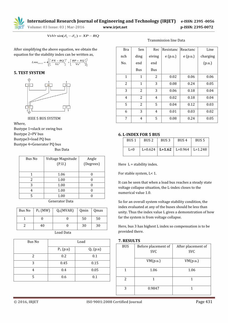
5. TEST SYSTEM
IEEE 5 BUS SYSTEM
Where,
Bustype 1=slack or swing bus
Bustype 2=PV bus
Bustype3=load PQ bus
Bustype 4=Generator PQ bus
Bus Data
Bus No Voltage Magnitude
(P.U.)
Angle
(Degrees)
1 1.06 0
2 1.00 0
3 1.00 0
4 1.00 0
5 1.00 0
Generator Data
Bus No PG (MW) QG(MVAR) Qmin Qmax
1 0 0 50 50
2 40 0 30 30
Load Data
Bus No Load
PL (p.u) QL (p.u)
2 0.2 0.1
3 0.45 0.15
4 0.4 0.05
5 0.6 0.1
Transmission line Data
Bra
nch
No.
Sen
ding
end
Bus
Rec
eiving
end
Bus
Resistanc
e (p.u.)
Reactanc
e (p.u.)
Line
charging
(p.u.)
1 1 2 0.02 0.06 0.06
2 1 3 0.08 0.24 0.05
3 2 3 0.06 0.18 0.04
4 2 4 0.02 0.18 0.04
5 2 5 0.04 0.12 0.03
6 3 4 0.01 0.03 0.02
7 4 5 0.08 0.24 0.05
6. L-INDEX FOR 5 BUS
BUS 1 BUS 2 BUS 3 BUS 4 BUS 5
L=0 L=0.624 L=1.62 L=0.964 L=1.248
Here L = stability index.
For stable system, L< 1.
It can be seen that when a load bus reaches a steady state
voltage collapse situation, the L-index closes to the
numerical value 1.0.
So for an overall system voltage stability condition, the
index evaluated at any of the buses should be less than
unity. Thus the index value L gives a demonstration of how
far the system is from voltage collapse.
Here, bus 3 has highest L index so compensation is to be
provided there.
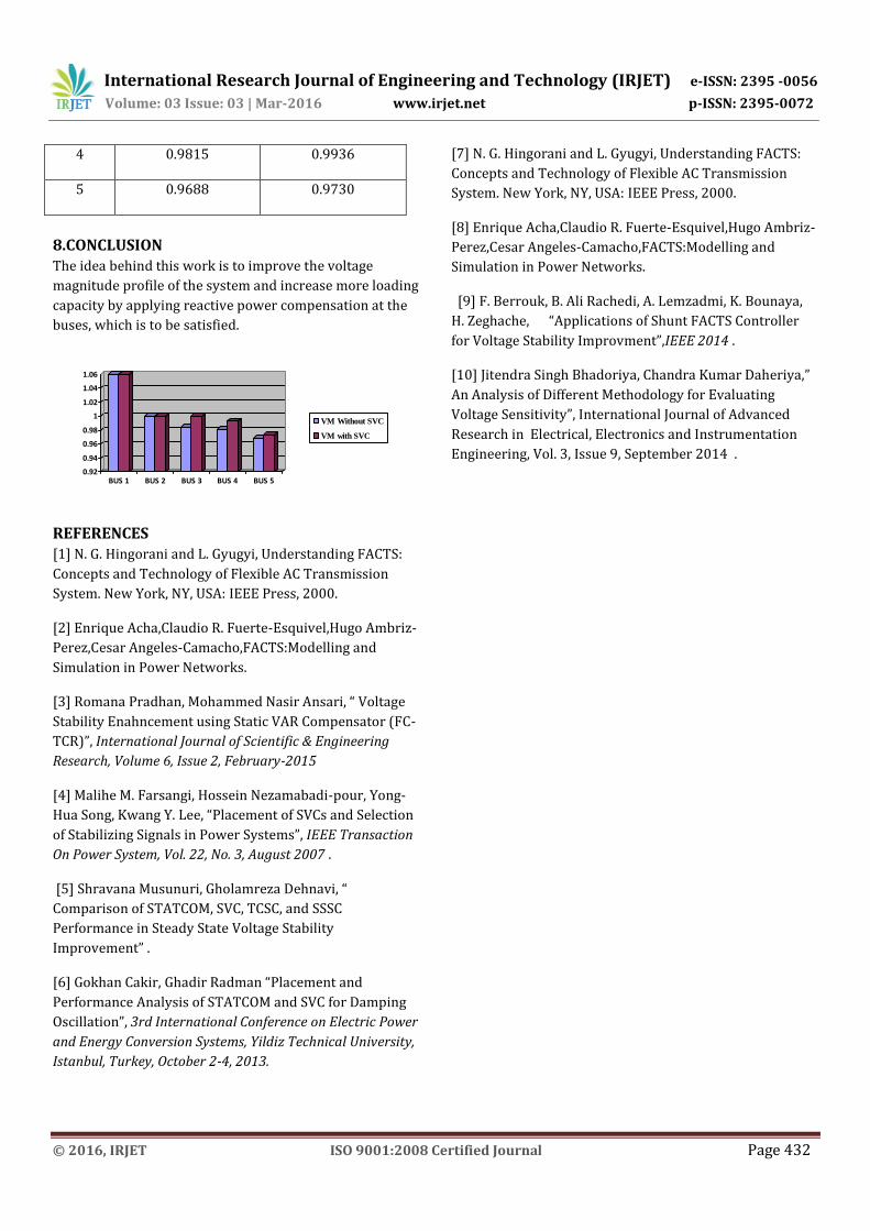
7. RESULTS
BUS Before placement of
SVC
After placement of
SVC
VM(p.u.) VM(p.u.)
1 1.06 1.06
2 1 1
3 0.9847 1
RQXPVsVr )sin( 21
2
2
2.).( 4Vs
XQRP
Vs
RQPXLmn up
International Research Journal of Engineering and Technology (IRJET) e-ISSN: 2395 -0056
Volume: 03 Issue: 03 | Mar-2016 www.irjet.net p-ISSN: 2395-0072
© 2016, IRJET ISO 9001:2008 Certified Journal Page 432
4 0.9815 0.9936
5 0.9688 0.9730
8.CONCLUSION The idea behind this work is to improve the voltage
magnitude profile of the system and increase more loading
capacity by applying reactive power compensation at the
buses, which is to be satisfied.
0.92
0.94
0.96
0.98
1
1.02
1.04
1.06
BUS 1 BUS 2 BUS 3 BUS 4 BUS 5
VM Without SVC
VM with SVC
REFERENCES
[1] N. G. Hingorani and L. Gyugyi, Understanding FACTS:
Concepts and Technology of Flexible AC Transmission
System. New York, NY, USA: IEEE Press, 2000.
[2] Enrique Acha,Claudio R. Fuerte-Esquivel,Hugo Ambriz-
Perez,Cesar Angeles-Camacho,FACTS:Modelling and
Simulation in Power Networks.
[3] Romana Pradhan, Mohammed Nasir Ansari, “ Voltage
Stability Enahncement using Static VAR Compensator (FC-
TCR)”, International Journal of Scientific & Engineering
Research, Volume 6, Issue 2, February-2015
[4] Malihe M. Farsangi, Hossein Nezamabadi-pour, Yong-
Hua Song, Kwang Y. Lee, “Placement of SVCs and Selection
of Stabilizing Signals in Power Systems”, IEEE Transaction
On Power System, Vol. 22, No. 3, August 2007 .
[5] Shravana Musunuri, Gholamreza Dehnavi, “
Comparison of STATCOM, SVC, TCSC, and SSSC
Performance in Steady State Voltage Stability
Improvement” .
[6] Gokhan Cakir, Ghadir Radman “Placement and
Performance Analysis of STATCOM and SVC for Damping
Oscillation”, 3rd International Conference on Electric Power
and Energy Conversion Systems, Yildiz Technical University,
Istanbul, Turkey, October 2-4, 2013.
[7] N. G. Hingorani and L. Gyugyi, Understanding FACTS:
Concepts and Technology of Flexible AC Transmission
System. New York, NY, USA: IEEE Press, 2000.
[8] Enrique Acha,Claudio R. Fuerte-Esquivel,Hugo Ambriz-
Perez,Cesar Angeles-Camacho,FACTS:Modelling and
Simulation in Power Networks.
[9] F. Berrouk, B. Ali Rachedi, A. Lemzadmi, K. Bounaya,
H. Zeghache, “Applications of Shunt FACTS Controller
for Voltage Stability Improvment”,IEEE 2014 .
[10] Jitendra Singh Bhadoriya, Chandra Kumar Daheriya,”
An Analysis of Different Methodology for Evaluating
Voltage Sensitivity”, International Journal of Advanced
Research in Electrical, Electronics and Instrumentation
Engineering, Vol. 3, Issue 9, September 2014 .
Related Documents
![52407115 Voltage Stability[1]](https://static.cupdf.com/doc/110x72/577d225a1a28ab4e1e97265d/52407115-voltage-stability1.jpg)