40 Surface Water Control Diverting surface water off the trail should be near the top of your list of priorities. Run- ning water erodes tread and support structures and can even lead to loss of the trail itself. Standing water often results in soft boggy tread or tread and support structure failure. Water is wonderful stuff—just keep it off the trail. The very best drainage structures are those designed and installed during the original construc- tion. These include outsloping the tread and grade dips. We’ve already discussed outsloping. Let’s move on to the next best drainage choice, grade or drain dips. The classic mark of good drainage is that it is self maintaining, requiring minimal care. Grade Dips The best grade dips are designed and built during the original construction. These are also called terrain dips, Coweeta dips, and swales. Other versions, often called rolling grade dips, or drain dips, can be built on most sidehill trails or constructed to replace waterbars. The basic idea is to use a reversal in grade to force water off the trail without the need for any other structure. Terrain dips use grade reversal to take advantage of natural dips in the trail. These need to be planned into the trail when it is first laid out. The grade of the trail is reversed for about 3 to 5 m (10 to 15 ft), then “rolled” back over to resume the descent. A trail Trail tread Prevailing grade Trail tread outsloped 2% thru this area 10% ➛ ➛ 10% ➛ ➛ ➛ ➛ ➛ ➛ ➛ ➛ Grade dips ➛ Grade dips ➛ ➛ Coarse material that won't scour Typical Dip Profile Figure 18—Grade dips are much more effective than waterbars and require less maintenance. Along with outsloping, they are the drainage structure of choice. Typical 3 m Typical 1.5 m ➛ ➛ 41 that lies lightly on the land will take advantage of each local drainage to remove water from the tread (Figure 18) as the trail winds around trees and rocks. The terrain dip, which uses existing terrain as the control point for the grade reversal, is a natural part of the landscape. The beauty of terrain dips is that water collected from the hillside is not intercepted and carried by the tread. These grade dips are the most unobtrusive of all drainage structures if constructed with smooth grade transitions, and they require very little maintenance. Be sure to protect the drain outlet by placing guide structures along the lower edge of the tread above or below the outlet. Another kind of grade dip is the rolling grade dip, which consists of a short reversal of grade in the tread. These can be designed into most sidehill trails. If a trail is descending at 7-percent grade, a short climb of, say, 3 to 5 m (10 to 20 ft) at 3 percent, followed

Welcome message from author
This document is posted to help you gain knowledge. Please leave a comment to let me know what you think about it! Share it to your friends and learn new things together.
Transcript
40
Surface WaterControlDiverting surface water off the trail shouldbe near the top of your list of priorities. Run-
ning water erodes tread and support structuresand can even lead to loss of the trail itself.
Standing water often results in soft boggy treador tread and support structure failure. Water is
wonderful stuff—just keep it off the trail.
The very best drainage structures are thosedesigned and installed during the original construc-
tion. These include outsloping the tread and grade dips.We’ve already discussed outsloping. Let’s move on to the nextbest drainage choice, grade or drain dips. The classic mark ofgood drainage is that it is self maintaining, requiring minimal care.
Grade Dips
The best grade dips are designed and built during the originalconstruction. These are also called terrain dips, Coweeta dips,and swales. Other versions, often called rolling grade dips, ordrain dips, can be built on most sidehill trails or constructed toreplace waterbars. The basic idea is to use a reversal in grade toforce water off the trail without the need for any other structure.
Terrain dips use grade reversal to take advantage of natural dipsin the trail. These need to be planned into the trail when it is firstlaid out. The grade of the trail is reversed for about 3 to 5 m (10to 15 ft), then “rolled” back over to resume the descent. A trail
Trail tread
Prevailing grade
Trail tread outsloped 2% thru this area10%
➛
➛
10%
➛
➛
➛
➛
➛
➛
➛
➛Grade dips➛Grade dips
➛
➛
Coarse material that won't scour
Typical Dip Profile
Figure 18—Grade dips are much more effective than waterbars andrequire less maintenance. Along with outsloping, they are the drainagestructure of choice.
Typical 3 m
Typical1.5 m
➛
➛
41
that lies lightly on the land will take advantage of each localdrainage to remove water from the tread (Figure 18) as the trailwinds around trees and rocks. The terrain dip, which uses existingterrain as the control point for the grade reversal, is a naturalpart of the landscape.
The beauty of terrain dips is that water collected from the hillsideis not intercepted and carried by the tread. These grade dips arethe most unobtrusive of all drainage structures if constructed withsmooth grade transitions, and they require very little maintenance.Be sure to protect the drain outlet by placing guide structuresalong the lower edge of the tread above or below the outlet.
Another kind of grade dip is the rolling grade dip, which consistsof a short reversal of grade in the tread. These can be designedinto most sidehill trails. If a trail is descending at 7-percent grade,a short climb of, say, 3 to 5 m (10 to 20 ft) at 3 percent, followed

42
Figure 19—Rolling grade dip designed into the construction of the trail.
by a return to the descent, constitutes a rolling grade dip (Figure19). Water running down the trail cannot climb over the shortrise and will run off the outsloped tread at the bottom of the dip.The beauty of this structure is that there is nothing to rot or bedislodged. Maintenance is simple.
If the grade is steep, the tread carries a lot of water, traffic is high,or the soils are erosive, a drain dip may need some additionalstrengthening. Sometimes a shallow water channel can be con-structed in the last several meters of tread leading into the dip.Water follows the channel off the tread without slowing down anddepositing soil and debris. A spillway may be needed if there is apotential for headcut erosion in the fillslope. The secret is to keepthe water moving at a constant velocity until it is all the way offthe tread.
Grade dips should be placed frequently enough to prevent waterfrom building enough volume and velocity to carry off your treadsurface. Grade dips are pointless at the very top of grades unlessthey intercept significant amounts of slope drainage. Usually mid-slope is the best location. Grade dips also should not introducesediment-laden water into live streams.
43
We encourage the use of reinforced grade dips instead of waterbars at most locations where waterbars have been traditionally used. Here’s why—
By design, water hits the waterbar and is turned. The water slows down and sediment drops in the drain. The number one cause of waterbar fail- ure is sediment filling the drain until the water tops the bar and continues down the tread. The bar becomes useless. You can build a good grade dip quickerthan a waterbar, and it works better.
Yet another grade dip is the reinforced or armored grade dip. Inthis dip, a curved water channel is constructed and an angled(like a waterbar) reinforcing bar of rock or wood is placed at thetop of the grade reversal. The bar is placed in an excavatedtrench, with its top edge flush with the existing tread surface soit’s not an obstacle to traffic. Essentially, this is a buried waterbar.
This short reinforced grade dip can be built to replace waterbarson existing trails, especially trails used by wheeled vehicles. Well-located waterbars can be converted by constructing a curvedwater channel and recontouring the outslope from the top of thebar. For longevity it is best if the bar is reseated so that the topedge is flush with the existing tread surface and the channel isconstructed with the correctly angled bar as the reference point.
The outlet is critical. It should be at least 500 mm (1.5 ft) wide,and outsloped. In shallow dips the task is to prevent berms, soilbuildup, and puddling. Reinforced spillways may also be needed.
Waterbars
The waterbar is thesecond mostcommon drainagestructure, after out-sloping. Water movingdown the trail is turnedby contact with thewaterbar and, intheory, is directedoff the lower edgeof the trail. Waterbarsare usually the mostdysfunctionaltread structuresin all of the trailworld. Yet trail crewsannually install or reinstall them by the thousands.
44
On grades less than 5 percent, waterbars are less susceptible toclogging (unless they serve a long reach of tread or are in veryerodible tread material). On steeper grades (15 to 20 percent),waterbars are very prone to clogging if the bar is at less than a 45°angle to the trail. Waterbars are mostly useless at grades steeperthan 20 percent. At these grades a very fine line exists betweenclogging the drain and eroding it (and the bar) away.
Most waterbars are dysfunctional because they are not installed atthe right angle and are too short. The waterbar needs to be anchored300 mm (12 in) into the cutslope and still extend 300 mm (12 in)into the fillslope. If your tread is 600 mm (24 in) wide, the bar mustbe 1.7 m (5 ft 6 in) long to be correctly installed at a 45° angle. Abar fitted at an angle of 60° must be 2.4 m (7 ft, 7 in) long. Widertread requires a longer bar. When the bar is cut too short, theusual response is to install it at a lesser angle. Then it clogs.
Poorly constructed and maintained waterbars also become obsta-cles. Most waterbars are installed with one-third to one-half of thebar material above the existing tread surface. Some crews eveninstall bars with exposed faces taller than 150 to 200 mm (6 to 8in). On grades steeper than 7 percent (particularly in erodiblesoils), the soil placed on the tread below the waterbar is rapidlylost to traffic and water erosion. The structure becomes a “lowhurdle” for travelers.
Wimpy little wooden bars less than 150 mm (6 in) in diameter wearor clog quickly into uselessness. Often they rot away in just a fewyears. Another problem with wooden waterbars is that horseskick them out.
Cyclists of all sorts hate wooden waterbars because of the hazardthey present to wheeled traffic. The exposed angled surface canbe very slippery, leading to crashes when the wheel slides side-ways down the face of the bar. The rider continues down the trailwithout the cycle. As the grade increases, the angle of the bar(and often the face height) is increased to prevent sedimentation.This raises the crash-and-burn factor.
45
Riprap tray➛
➛ ➛
➛
➛
➛
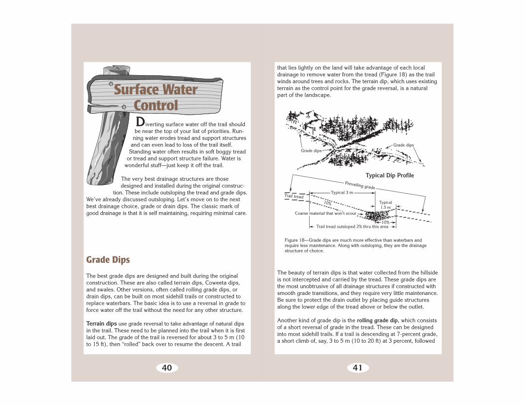
Figure 20—Reinforced or armored waterbars.
Backed Waterbar With Riprap Tray
DRAINAGE DIRECTION ➛
Rockwaterbar Retainer bar
➛
Are waterbars ever useful? Sure. Wood or rock waterbars are use-ful on foot and stock trails where a tripping hazard is acceptable,especially at grades less than 5 percent. Also consider reinforcedwaterbars where you don’t have much soil to work with and inareas that experience occasional torrential downpours (Figure 20).
The bar helps keep traffic from wearing a water carrying groovethrough the drain. Install the bar at an angle of at least 45° andincrease the angle as the grade approaches 5 percent or if thesoils are very erodible (Figures 21 and 22).
Remember that high-faced bars are barriers to wheeled traffic. Ontrails that serve wheeled traffic, use either reinforced grade dipsor rubber waterbars instead of traditional waterbars. Bikers do notlike waterbars because of the “crash factor.” It is important toplace rubber waterbars such that wheeled vehicles cannot goaround them (creating a water channel around the waterbar). Besure to cut the rubber belting so that it bends easily under thewheel. A stiff rubber bar at a 45° to 60° angle can cause wrecks(Figure 23).
TOP VIEW
SIDE VIEW

46
Figure 21—Waterbars need to be constructed at a 45 to 60° angle to the trail.Water should run off the trail before hitting the waterbar.
47
Square treated timber 200 mm
Embed log 1⁄3 (min.)Log 300 mmdiameter
40d barbed orring shank nails
➛
ANCHORING METHODS
50 by 450 mmsquare hardwoodstakes
Trail treadRock anchor Trail tread
➛
100 mm (min.)
Embed 1⁄3 (min.)Steel pin flush with top, rebar #4 by 450 mm
Figure 22—Logs used for waterbars need to be peeled (or treated with preserv-ative), extended at least 300 mm (12 in) into the bank, staked or anchored,and mostly buried.
➛
➛Embed log 300 mm(min.) into bank.
➛
➛Extend log 300 mmbeyond edgeof trail.
Top of waterbar is 150 mmabove surface on upgrade side.
➛
Log or Treated Timber Waterbar and Anchors
➛Down grade
Toe of bank
➛
➛
Skewwaterbar45 to 60°
Outslo
pe to
day
light
➛
➛
Typi
cal o
utslo
pe
6 to
10%
➛
Log flushwith tread ondown-gradeside.

48
Figure 23—Rubber belt waterbars are good choices on trails used by wheeledvehicles. They are not as good as reinforced grade dips.
Conveyor beltrubber
T R A I L
T R E A D
45° to 60° angle from trail tread
Rubber Belting Waterbar
Belting 10 mm thick
Trail tread surface
Excavate and compact around waterbar.
50 x 150 mm treated lumber on each side
50 mm
Make cuts in belting 300 mmapart for better spring-back.
30d galvanized nailson alternate sides
Keep nails a minimum of50 mm from edges of timber.
Treated timber
Nailing and Cutting Detail
150 mm
200 mm
➛
➛
➛
➛
➛
➛
➛
➛
150mm
➛
➛
➛
Belting
➛
➛
➛
➛
➛
➛
➛
➛
➛➛
Lag screws, bolts, or30d ringshank nails
Treated lumber(50 x 150 mm)
49
Think of your waterbar (wood or rock) as a backup to a dip in the trail. Dig the bar first. Make sure it is seated flush, anchored into the cutslope, and at a good angle. Then construct the dip and outlet to match.
For rock waterbars, use rectangular rocks, “chunkers,” butted together, not over- lapped. Start with your heaviest rock at the downhill side—that’s your “keystone.” Lay rocks in from there until you tie into the bank.
Maintaining the Drain
The number one enemy of simple drains is sediment. If the drainclogs, the water you are trying to get rid of either continues erod-ing its way down the tread, or just sits there in a puddle. Your jobis to keep that water off, Off, OFF the tread!
The best drains are “self cleaning.” But in the real world mostdrains collect debris and sediment; this must be removed beforethe drain stops working. Since a long time may pass betweenmaintenance visits, the drain needs to handle annual high volumerunoff without failing.
Most problem drains are waterbars. If the water is slowed by hit-ting the waterbar, sediment builds up. This can be compoundedby inadequate outsloping or an outlet that is too narrow. The extratime it takes to rebuild the offending bar into a functional drain willpay off almost immediately (Figure 24).
The best cure for a waterbar that forces the water to turn tooabruptly is to rebuild the structure into a reinforced grade dip. Thereset bar and curved water channel keep the sediment-laden

50
Figure 24—The key to waterbar maintenance is to ensure that sediment will notclog the drain before the next scheduled maintenance. Embed the rocks orlogs a little deeper, cover them with soil, and you have a reinforced grade dip.
water moving through the outlet. If this is not an option, the nextbest move is to reset the waterbar at a steeper angle. Usually alonger bar will be needed.
TR
AIL
TR
EA
D
Downslope—directionof water flow
Reinforce outlet area if eroded.
Waterbarconstructed at 45° angle.Reset loose ormissing rocksand logs.
Thoroughly dig material
out of this area—at least two
shovel blades wide. Use for backing
below waterbar.
51
A lot of learning takes place when you slosh over a wet trail in a downpour and watch what the water is doing and how your drains and structures are holding up.
If a lot of tread has eroded below the bar, reset the bar so it isflush with the existing tread height. Regrade the water channeland outlet drain. On gentle trails, tamp the excavated mineral soilsediment into the tread on the downhill side of the bar. Scatter anyorganic debris well off the trail.
At grades steeper than 7 to 10 percent, or in highly erodible soils,borrow material placed below the bar will usually erode awayquickly. This is particularly true on waterbars with high faces.Downhill traffic, especially packstock, will step in the same placeevery time and dislodge any new material you place there. If asignificant step-off exists below the bar, reseat the bar flush withthe existing tread level and deepen the drain above the bar.
Dig drains and leadoff ditches wide enough to prevent cloggingby debris, and graded so water does not slow before it is off thetrail. Ditches that allow water to return to the tread below the drainneed to be reconstructed so this doesn’t happen.
You may need to install additional water control structures iferosion is evident. Figure out where the water is coming from andwhere it is likely to go. Think about soil type, slope gradient,distance of flow, and volume of water before you start moving dirt.
Eroded trails do not alwaysbecome major problems.Many eventually stabilize ifthe trail surface is rocky, anduse, water, and slopesare moderate. The key ques-tion is whether the loss oftread will materially affectthe designed challenge andrisk levels of the trail. If not,the erosion isn’t significant.It is exceedingly rare for aneroding trail to have a signif-icant effect on aquatic or riparian habitat or stream function.

52
Ponding
Adequate puddle drains are important. Puddles may produceseveral kinds of tread damage. Traffic going around puddles maywiden the tread (and eventually the puddle). Standing waterusually weakens the tread and fillslopes. It can cause a bog todevelop if the soils are right. Traffic on the soft lower edge of apuddle can lead to step-throughs and cause tread creep.
When a crew takes a swipe at the berm with a shovel or kicks ahole through it—that’s useless puddle control. These small open-ings are rapidly plugged by floating debris or the mud-mooshingeffect of passing traffic. The puddle lives on.
Effective puddle prevention requires constructing a wide drain.The ultimate drain is when the entire section of tread is outsloped.If terrain prevents such outsloping, the next best solution is to cuta puddle drain at least 600 mm (24 in) wide extending across theentire width of the tread. Dig the drain deep enough to ensure thatthe water can escape the tread. Feather the edges of the drain intothe tread so travelers don’t trip over them. Plant guide structuresalong the lower edge of the tread at either side of the drain to keeptraffic in the center. In a really long puddle, construct several drainsat what appear to be the deepest spots.
Trails in Wet Areas
Very few critters like to get their feet wet.There are a few exceptions, of course. Otters,
beavers, goofy retriever dogs, motorcyclists,and most young children like to jump right in.
But the rest of us—horses, llamas, and stodgyadult hikers—will often go to great lengths to
avoid getting our feet wet or going for anunplanned swim. This section deals with a rangeof options for getting trail traffic from one side ofwet ground to the other.
Because nearly every technique for fixing trails in boggy areas isexpensive and needs to be repeated periodically, relocating theproblem section of trail should be considered first. Scouting forsuitable places to relocate trails and reviewing soil maps will betime well spent. The alternative route should bypass extensiveboggy areas, be on a slope for better drainage, and have mineralrather than organic soil for its tread. Don’t reroute a problem sec-tion of trail to another boggy piece of ground. If you do, the resultwill be two problem sections instead of one.
Sometimes, improved drainage will cure the problem. If so, thisis a much less costly solution than other alternatives. Placingstepping stones is another technique for crossing bogs andstreams. Stepping stones should be large, fairly flat on top, andpartially buried in the streambed. Space the stones for the aver-age stride, remembering that trails are for kids, too. It shouldn’tbe necessary to jump from stone to stone.
Moving up in cost and complexity, two types of structures—turn-pike and puncheon—are commonly constructed to provide drytrails through wet or boggy areas. Using geosynthetics in combi-nation with these techniques can often result in a better tread
53
54
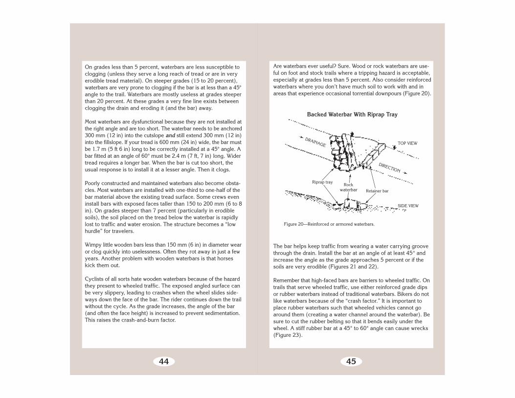
Figure 25—This boardwalk relies on pilings for support. Helical earth anchorscan also support the structure.
with less fill. Rock and fill causeways are popular in some areaswhere hardened trails are needed to cross fragile alpine meadows.
In situations where long spans are needed high above the ground,or for crossing streams, a trail bridge is usually needed insteadof puncheon. Bridges require special designs fitted to eachapplication. Engineering approval is needed before constructingeither a standard or special design bridge.
Boardwalks are common in some parts of the country, particu-larly parts of Alaska and in the Southeast. These can range fromfairly simple structures placed on boggy surfaces, to elevatedboardwalks over marshes or lake shores, as are sometimes foundat interpretive centers (Figure 25).
Let’s look at some of these alternatives in more detail.
55
300 mm
Ditch
➛
➛
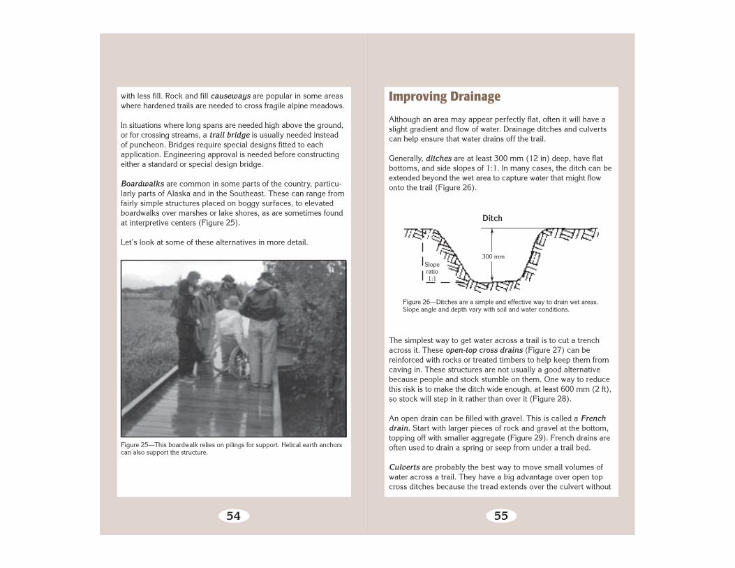
Figure 26—Ditches are a simple and effective way to drain wet areas.Slope angle and depth vary with soil and water conditions.
Sloperatio1:1
Improving Drainage
Although an area may appear perfectly flat, often it will have aslight gradient and flow of water. Drainage ditches and culvertscan help ensure that water drains off the trail.
Generally, ditches are at least 300 mm (12 in) deep, have flatbottoms, and side slopes of 1:1. In many cases, the ditch can beextended beyond the wet area to capture water that might flowonto the trail (Figure 26).
The simplest way to get water across a trail is to cut a trenchacross it. These open-top cross drains (Figure 27) can bereinforced with rocks or treated timbers to help keep them fromcaving in. These structures are not usually a good alternativebecause people and stock stumble on them. One way to reducethis risk is to make the ditch wide enough, at least 600 mm (2 ft),so stock will step in it rather than over it (Figure 28).
An open drain can be filled with gravel. This is called a Frenchdrain. Start with larger pieces of rock and gravel at the bottom,topping off with smaller aggregate (Figure 29). French drains areoften used to drain a spring or seep from under a trail bed.
Culverts are probably the best way to move small volumes ofwater across a trail. They have a big advantage over open topcross ditches because the tread extends over the culvert without

56
Open-Top Cross Drain Culvert
Rough-cut50 x 300 mm
➛
➛
Structure angled about 45° from trail
T R A I L
T R E A D
➛Bolt➛
Galvanized steelpipe spacers
➛
➛
Figure 27—Open-top cross drains or culverts are not often chosen becausethey are a hazard to livestock, hikers, and bikers.
Figure 28—Wide cross drain and causeway.
57
TOP VIEW
Water flow
French Drain or Rock Underdrain
END VIEW
Figure 29—Wrapping French drains with geotextile helps prevent clogging.These are used to drain low-flow springs and seeps.
1 m minimum
➛
➛
➛
➛150 mm minimum
➛
Wrap ingeotextile
25- to100-mm
filter rocks➛
Overlap geotextile300 mm on top➛
➛
interruption (Figure 30). Metal or plastic culverts can be installedeasily, or the culverts can be constructed out of rock. Dig a ditchacross the trail as wide as the culvert and somewhat deeper.

58
Figure 30—Culverts need to be installed at a sharp enough angle to preventsediment from being deposited.
Bed the culvert in native soil shaped to fit the culvert. There alsoneeds to be sufficient drop, about 3 percent, from one side to theother so water will flow through the culvert without droppingsediment. The culvert needs to be covered with 150 mm (6 in)or more of fill. Cut the culvert a little longer than the trail width,and build a rock facing around each end to shield it from view andprevent it from washing loose. Often a rock-reinforced spillwaywill reduce headcutting and washouts.
The local trail manager may have definite preferences for metal,plastic, wood, or rock culverts. Synthetic materials may be tabooin wilderness. Plastic is often preferable to metal because it islightweight, easy to cut, and less noticeable. Painting the ends ofaluminum or steel culverts helps camouflage them. Use a culvertwith a diameter large enough to handle maximum storm runoffand to be accessible for cleaning with a shovel or combinationtool. Usually this means at least a 260-mm (9-in) diameterculvert.
Rock culverts offer a chance to display some real trail skills.Begin by laying large, flat stones in a deep trench to form thebottom of the culvert. In some installations, these bottom rocks
59
Figure 31—Rock culverts may also have stones laid along thebottom of the culvert. The perfect rocks shown here are seldomfound in nature, except reportedly in Southwestern sandstone.
Streambed
Rock sidewalls
➛
Use flatrocks.
Water
Direction of trail
➛
➛
Rock Culvert
may not be necessary. Then install large, well-matched stonesalong either side of the trench. Finally, span the side rocks withmore large, flat rocks placed tightly together, enough to withstandthe expected trail use. Cover the top rocks with tread material tohide and protect the culvert. These culverts, too, need to be largeenough to clean out easily. The rocks should not wiggle (Figure 31).
Water flowing toward a culvert often carries a lot of silt. If thewater slows as it goes under the trail, the silt may settle out andclog the culvert. A good way to help prevent this from happeningis to construct a settling basin at the inlet to the culvert (Figure32). This is a pit at least 300 mm (1 ft) deeper than the base ofthe culvert. It can be lined with rocks as desired. The idea is thatsediment will settle out here, where it is much easier to shovelaway, rather than inside the culvert.

60
Geosynthetics
Geosynthetics are synthetic materials (usually made from hydro-carbons) that are used with soil or rock in many types ofconstruction. Geosynthetics can increase the effectiveness ofconstruction methods and offer some additional alternatives totraditional trail construction practices.
Geosynthetics perform three major functions: separation,reinforcement, and drainage. Geosynthetic materials include geo-textiles (construction fabrics), geonets, sheet drains, geogrids,and geocells. All these materials become a permanent part of thetrail, but must be covered with soil or rock to prevent deteriora-tion by ultraviolet light or damage by trail users.
Geotextiles (Figure 33) are the most widely used geosyntheticmaterial. Sometimes they are called construction fabrics. They aremade from long-lasting synthetic fibers bonded to form a fabric.
T R A I L T R E A D
Settling Basin
Rock
culvert
➛
Excavatedsettling basin
STRE
AM
FLOW
➛
Figure 32—Settling basins help prevent culvert clogging.
➛61
Figure 33—Felt-like geotextiles are easier to work with than heat-bonded, slit-film, or woven products that have a slick texture.
Geotextiles are often used in trail turnpike or causeway construc-tion. They serve as a barrier between the silty, mucky soil beneaththe fabric and the mineral, coarse-grained, or granular soil placedas tread material on top of the geotextile. The importance of sepa-ration cannot be overemphasized. It takes only about 20 percentsilt or clay before mineral soil takes on the characteristics of mud—and mud is certainly not what you want for your tread surface.Most geotextiles commonly used in road construction work fortrail turnpikes. The fabric should allow water to pass through it,but have openings of 0.3 mm or smaller to prevent silt frompassing through.
Geotextile is sensitive to ultraviolet light. It readily decomposeswhen exposed to sunlight. Unexposed, it lasts indefinitely. Alwaysstore unused geotextile in its original wrapper.
They are primarily used for separation and reinforcement over wet,unstable soils. They have the tensile strength needed to supportloads and can allow water, but not soil, to seep through. Nonpor-ous geotextiles can be used in drainage applications to interceptand divert ground water.
62
Figure 34—The net-like core of geonet allows drainage.
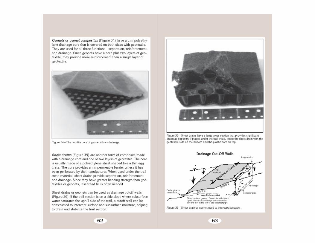
Sheet drains (Figure 35) are another form of composite madewith a drainage core and one or two layers of geotextile. The coreis usually made of a polyethylene sheet shaped like a thin eggcrate. The core provides an impermeable barrier unless it hasbeen perforated by the manufacturer. When used under the trailtread material, sheet drains provide separation, reinforcement,and drainage. Since they have greater bending strength than geo-textiles or geonets, less tread fill is often needed.
Sheet drains or geonets can be used as drainage cutoff walls(Figure 36). If the trail section is on a side slope where subsurfacewater saturates the uphill side of the trail, a cutoff wall can beconstructed to intercept surface and subsurface moisture, helpingto drain and stabilize the trail section.
Geonets or geonet composites (Figure 34) have a thin polyethy-lene drainage core that is covered on both sides with geotextile.They are used for all three functions—separation, reinforcement,and drainage. Since geonets have a core plus two layers of geo-textile, they provide more reinforcement than a single layer ofgeotextile.
63
Figure 35—Sheet drains have a large cross section that provides significantdrainage capacity. If placed under the trail tread, orient the sheet drain with thegeotextile side on the bottom and the plastic core on top.
Directi
on of
Trav
elFill
material
Sheet drain or geonet. Geotextile side facesuphill to intercept seepage and is insertedinto the slot in the top of the collector pipe.
Seepage
Collector pipe
Large rocks
SURFACE
Outlet pipe orsheet drain
Figure 36—Sheet drain or geonet used to intercept seepage.
ORIGINAL
➛
➛
➛
➛
➛
Drainage Cut-Off Walls

64
Figure 37—Geogrids are normally placed on top of a layer of geotextile to obtainseparation from saturated soils.
Geogrids (Figure 37) are made from polyethylene sheeting thatis formed into very open grid-like configurations. Geogrids aregood for reinforcement because they have high tensile strengths,and coarse aggregate can interlock into the grid structure.Geogrids are normally placed on top of a layer of geotextile toobtain separation from saturated soils in wet areas.
Concrete grid blocks are another technique for armoring switch-back turns or steeper slopes, especially on trails designed formotorized traffic.
Geocells (Figure 38) are usually made from polyethylene stripsbonded to form a honeycomb structure. Each of the cells is filledwith backfill and compacted. Geocells are good for reinforcement,reduce the amount of fill material required, and help hold the fill inplace. Geocell usually has geotextile under it to provide separationfrom saturated soils. The grids need to be covered with soil sothey will never be exposed. Exposed geocells present a substantialhazard to vehicles due to loss of traction.
65
Figure 38—Geocell usually has geotextile under it to provide separation fromsaturated soils.
Multiple layers of filled geocells, each level offset to provide suffi-cient batter, are used as retaining walls. Vegetation grows in the“flower pot” cells along the face of the wall, providing attractivecamouflage (Figure 39).
Turnpikes
Turnpikes are used to elevate the trail above wet ground. Thetechnique uses fill material from parallel side ditches and fromoffsite to build up the trail base higher than the surrounding watertable. Turnpike construction is used to provide a stable trail base

66
Figure 39—“Flower pot” retaining wall of geocells.
in areas of high water table and fair to well drained soils. Turnpikesare practical up to 10 percent trail grade (Figure 40).
Figure 40—Trail turnpike.
Slope
➛
➛
➛
Leadoffditch
Turnpike With Leadoff Ditch
67
A turnpike should be used primarily in flat areas with 0 to 20 percentsideslope where there is wet or boggy ground. The most importantconsideration is to lower the water level below the trail base andcarry the water under and away from the trail at frequent intervals.Turnpikes requires some degree of drainage. When the ground isso wet that grading work cannot be accomplished and drainage isnot possible, use puncheon surfacing instead. However, a turnpikeis easier and cheaper to build and may last longer than puncheon.A causeway is another alternative where ground water saturationis not a problem but a hardened tread is needed.
Begin your turnpike by clearing the site wide enough for the trailtread plus a ditch and retainer log or rocks on either side of thetrail tread. Rocks, stumps, and stobs that would protrude abovethe turnpike tread or cause large rips in geotextiles should beremoved or at least cut flush below the final base grade.
Ditch both sides of the trail to lower the water table. Install geo-textile or other geosynthetic materials and retainer rocks or logs.Geotextile and geogrid should go under any retainer rocks or logs(Figure 41). Lay the geotextile over the top with no excavation,then fill over with high quality fill. An alternative method, onethat not only provides for separation between good fill and claybut also keeps a layer of soil drier than the muck beneath, is calledencapsulation, or the sausage technique. Excavate 250 to 300mm (10 to 12 in) of muck from the middle of the turnpike. Laydown a roll of geotextile the length of the turnpike, wide enough
Underlying boggy soil
Ground line
Slope 1:1
➛
Mineral soil
Sideditch
Figure 41—Place geotextile under the retainer logs or rocks before staking.
Geotextile Placement
CROSS SECTION
➛➛
Rock retainer option
➛1 mMinimum crown 50 mm
➛
➛
➛
Wooden stakes
Log retainers150 to 200 mm
Geotextile Sideditch
➛
➛30
0m
m
➛
➛

68
Log retainers
➛Wooden stakes
➛
Sideditch
➛
➛
Geotextile
➛
300-mm overlap
Underlying boggy soil
Ground lineSideditch
Rock retainer option
➛
➛
Sausage or Encapsulation Technique
CROSS SECTION
Figure 42—Sausage or encapsulation method.
Gravel or rock
to fold back over the top with a 300-mm (1-ft) overlap (Figure 42).Place 150 mm (6 in) of good fill, or even rocks, on top of thesingle layer of geotextile, then fold the geotextile back over thetop and continue to fill with tread material.
Rocks or logs can be used for retainers. Rocks last longer. If youuse logs, they should be at least 150 mm (6 in) in diameter andpeeled. Lay retainer logs in one continuous row along each edgeof the trail tread. The logs can be notched to join them, if desired.However, in some species notching may cause the logs to rotfaster (Figure 43).
Notched Retainer Log
Figure 43—Notched retainer log.
Notching
Spike
Notching
PEELED LOG
➛
➛
➛
69
Figure 44—Try this old Alaska trick if yourstakes tend to work up out of boggy ground.
Sharpen thebig end ofthe sapling.
Sapling Stake
Stak
e ap
prox
. 400
-mm
long
Stobs 50to 75 mm
Ground level
Anchor the logs with stakes or, better yet, large rocks along the out-side. Inside, the fill and surfacing hold the retainer logs (Figure 44).
Firm mineral soil; coarse-grained soils or granular material; orsmall, well-graded angular rock are needed for fill. Often it isnecessary to haul in gravel or other well-drained material tosurface the trail tread. If good soil is excavated from the ditch, itcan be used as fill. Fill the trail until the crown of the trail tread is50 mm (2 in) or a minimum of 2-percent grade above theretainers. It doesn’t hurt to overfill to begin with, as the fill willsettle.
Construct a dip, waterbar, or a drainage structure at each end ofthe turnpike where necessary to keep water from flowing onto thestructure. Keep the approaches as straight as possible comingonto a turnpike, to minimize the chance that stock or motorbikeusers will cut the corners and end up in the ditches.

70
Figure 45—Causeways create an elevated, hardened tread across seasonablywet areas.
Wall rocksDirt tread
Resodded old ruts Old ruts
Rocky fill
➛ ➛
➛
➛
➛
Causeways
Turnpike maintenance, especially recrowning, is particularlyimportant the year after construction; most of the soil settlingoccurs during the first year.
CausewaysA more environmentally friendly relative of the turnpike is thecauseway, essentially a turnpike without side ditches (Figure 45).Causeways filled with crushed rock have been successfully usedthroughout the Sierra Nevada and elsewhere to create an elevated,hardened tread across seasonally wet alpine meadows. Oftenmultiple parallel paths are restored and replaced with a singlecauseway. Causeways create less environmental impact thanturnpikes because ditches are not used and the water table is notlowered. The risk is that in highly saturated soils the causewaycould sink into the ground, a problem that geotextile can helpprevent.
71
Figure 46—Puncheon.
➛➛
Stringer
➛
Mud sill
Running planks
➛
Spacers
➛
Deck—plankshave approx.20-mm gaps
Curb or bull rail
➛
➛
600 mmminimum
Puncheon
Puncheon
Puncheon is a wooden walkway used to cross bogs or deepmuskeg, to bridge boulder fields, or to cross small streams. It canbe used where uneven terrain or lack of tread material makesturnpike construction impractical (Figure 46). Puncheon is alsopreferred over turnpike where firm, mineral soil cannot be easilyreached; puncheon can be supported on muddy surfaces betterthan turnpike, which requires effective drainage.
Puncheon resembles a short version of the familiar log stringertrail bridge. It consists of a deck or flooring made of sawn,treated timber or native logs placed on stringers to elevate thetrail across wet areas that are not easy to drain. Puncheon that isslightly elevated is termed surface puncheon. Puncheon placedflush with the wetland surface is known as subsurface puncheon.

72
Corduroy
Cover with soil
➛
Figure 47—Corduroy should be considered a temporary fix until a more perm- anent structure can be installed.
Sooner or later, you’ll probably hear the term, corduroy. Cordu-roy is basically a primitive type of puncheon. It consists of layingthree or more native logs on the ground as stringers with crosslogs laid side by side across the stringers and bound together withwire or nails (Figure 47). Corduroy should always be buried, withonly the tread exposed. Corduroy is notorious for not lasting verylong and consuming large amounts of material. It should only beused as a temporary measure.
Here’s how to build puncheon. First of all, the entire structuremust extend to solid mineral soil so soft spots do not develop ateither end. Approaches should be straight for at least 3 m (10 ft)coming up to a puncheon. Any curves either approaching or whileon the puncheon add to the risk of slipping, especially to stockand to mountain bike and motorcycle users.
To begin construction, install mud sills. These support the stringers.Mud sills can be made of native logs, treated posts, short treatedplanks, or precast concrete parking lot curb blocks. The mud sillsare laid in trenches at both ends of the area to be bridged at inter-vals of 1.8 to 3 m (6 to 10 ft) (Figure 48). They are approximatelytwo-thirds buried in firm ground. If firm footing is not available, userock and fill to solidify the bottom of the trench, increase the lengthof the sill log to give it better flotation, or use more sills for theneeded floatation. Enclosing rock and fill in geotextile minimizes
73
1.8 to 3.0 m apart
Stringer jointMud sills
Stringers
Tie stringer—place on double mudsill and drift pin to each mud sill.
TOP VIEW
Figure 48—Mud sill and stringer layout.
the amount of rock and fill required. For stability, especially inboggy terrain, the mud sills should be as long as practical up to2.5 m (8 ft).
Stringers made from 200-mm (8-in) peeled logs or treated timbersare set on top of the mud sills. They should be at least 3 m (10 ft)long and matched by length and diameter. Stringers also need tobe level with each other so the surface of the puncheon will belevel when the decking is added. Two stringers are sufficient forhiking trails, but for heavier uses, such as stock use, three arerecommended.
Notch the mud sills, if necessary, to stabilize the stringers and toeven out the top surfaces (Figure 49). To hold the stringers inplace, toenail spikes through the stringers to the mud sills or driveNumber 4 rebar (1⁄2 in) through holes in the stringers.
Next comes the decking. The thickness needs to be strong enoughfor the loads the structure will need to support. Lengths can be asnarrow as 460 mm (18 in) for a limited-duty puncheon for hikers.The decking should be 1.2 to 1.5 m (4 to 5 ft) long for puncheonsuitable for stock use.

74
Figure 49—When using logs, notch the mudsill—not the stringer.Do not notch them more than one third of their diameter.
B u r yMudsills
Stringers
Placementof log splice
L i n e
SIDE VIEW
Figure 50—Place decking planks on stringers to provide bearing for thefull width of the plank.
Do not spike decking to the center stringer, if you have one,because center spikes may work themselves up with time andbecome obstacles. Leave at least a 20-mm (3⁄4-in) gap betweendecking pieces to allow water to run off (Figure 50). Deckingshould be placed with tree growth rings curving down. Thisencourages water to run off rather than soak in and helps toprevent cupping.
Running planks are often added down the center for stock to walkon. Often the running planks are untreated because horseshoescut out the plank before wood has a chance to rot. Do not leavegaps between running planks because they can trap mountainbike or motorcycle wheels.
Steel drift pins, bolts, or rebar
25-mm spacersCurb logs
Notched mud sill logs
Decking
Runningplanks
Bury Line
75
Figure 51—Place a bulkhead or backing plate at each end of the puncheon.Approaches should have a rising grade so water will not run onto the structure.
Curb logs, also called bull rails, should be placed along each sideof the puncheon for the full length of the structure to keep trafficin the center. To provide for drainage, nail spacers between thecurb logs and the decking.
Finally, a bulkhead or backing plate needs to be put at each endof the structure to keep the stringers from contacting the soil(Figure 51). If the plate stays in place, do not spike it to the endsof the stringers. Spiking causes the stringers to rot faster.
In the rare case where puncheon is constructed on grades steeperthan 5 percent, treat the surface to reduce slipping. Use cleats,commercial fish netting, mineral roofing, or other surfacing.
Subsurface PuncheonSubsurface puncheon involves construction with the mud sill,stringers, and decking under the surface. This design depends oncontinual water saturation for preservation (Figure 52). Moisture,air, and wood are needed before wood can rot. Remove any oneof these and rot won’t occur. A good rule for reducing rot is tokeep the structure continually dry or continually wet. Totallysaturated wood will not rot because no air is present. Cover thesurface between the curb logs with a layer of gravel, wood chips,or soil to help keep everything wet.
Decking
Curb log
Spacer
Trail grade
Mineral
soil
Rock fill
Bulkhead
Stringer
Mud sill

76
Cover deck with gravel,soil, or wood chips.
Curb orbull rail
Figure 52—Subsurface puncheon with covered tread surfacing.
➛
➛
Deck
Mud sill
Curb or bull rail
➛
➛
SubsurfacePuncheon
With CoveredTread Surfacing
SurfacePuncheon
77
Crossing Streamsand Rivers
The Minimum Tool philosophy suggests that we get the job done with the least long-term impact while still meeting management objectives for an area. A few Minimum Tool questions for crossings are: • Do we really need a bridge here? Do we really need to be through here a month earlier each spring? • Will someone be killed or injured if we don’t provide an easier crossing? • Is this really the best place to cross this stream? • What alternatives do we have to cross this stream, including not crossing it at all? • Can we afford to do this? • What are the environmental and social conse- quences of a given type of crossing here? • Who will really care if we don’t build (or replace) a bridge? —It’s a wonderful thing to keep one’s feet dry. But it is expensive to keep feet dry in the backcountry.
Stream and river crossings present a chal-lenge to trail managers grappling with a mix of
user challenge, safety, convenience, cost, andesthetics. At one end of the use spectrum, a
bridge can allow people with disabilities, toddlers,and those new to the outdoors to experience the
trail with little risk. But bridges are expensive.Wilderness visitors who expect a challenge mayprefer a shallow stream ford. During high waterthese folks may opt for a tightrope walk across a
fallen log. Each kind of water crossing has consequences for therecreation experience and the lands being accessed. Choose wiselyfrom the spectrum of options before committing present andfuture resources to any given crossing.

78
Shallow Stream Ford or Gully Crossing Log Structure
Grade break shall be 300 mm(min) above high-water level.
Hand-placedrocks
Place stepping stones onupstream edge of tread.
High-water level
Top of bank
Level log dam and embed intoeach bank 300 mm minimum.Cut center notch100 to 200 mmwide, and 75 to 100 mm deep.
Downgrade 15percent or less.
➛
➛
➛ ➛
➛
Stream flow➛
➛
➛
TOP VIEW
Figure 53—Build fords when the water is low. Place stepping stones forhikers (continued on next page).
Constructed of gravelor small rocks
➛
TRA
IL TRE
AD
Shallow Stream Fords
A shallow stream ford is a consciously constructed crossing thatwill last for decades with a minimum of maintenance (barringmajor flood or debris torrent) and will provide a relatively lowchallenge to users.
The idea behind a shallow stream ford is to provide solid footing,at a consistent depth from one bank to the other. Most fords arenot designed to be used during high runoff, but are intended tobe used when flows are moderate to low. A ford for hikers and“nontraditional” packstock (like llamas and pack goats) shouldnot be more than 400 to 600 mm (16 to 24 in) deep (about kneehigh) during most of the use season. A horse ford (Figure 53)shouldn’t be deeper than 1 m (39 in).
79
SIDE VIEW
Tread-retaining barrier—peeledlog 400 mm (min), or rocks.Embed half the diameter intostreambed.
Imbed 60 kg (min)stepping stones.
Hand-placedrocks
➛
➛ ➛
Stream flow
Figure 53—(continued).
Fords should be located in wider, shallower portions of the stream.The approaches should climb a short distance above the typicalhigh water line so that water isn’t channeled down the tread. Avoidlocations where the stream turns, because the water will undercutapproaches on the outside of a turn.
The tread in the ford is level, ideally made of medium-sized gravel.This provides solid footing. The plan is to even out the flowthrough the ford so the gravel-sized material isn’t washed away,leaving only cobble or boulders.
You can do this by arranging a level riprap of big rocks (like aminiature dam) or anchoring a log about 1 to 2 m (3 to 7 ft)downstream from the trail centerline. The idea is to evenly slowthe water as it goes across the ford. This slowing effect can beenhanced by placing several rows of stepping stones or rocksupstream from the tread. These slow the water entering the fordand begin to even out the flow. Be sure these upper rocks are nottoo close to the trail to avoid a scouring effect.
On trails receiving motorized use, concrete planks or blocksplaced in soft stream bottoms can strengthen the trail tread for asolid crossing.
Well-constructed shallow stream fords are almost maintenancefree. Watch for deep spots developing in the crossing. Floods orseasonal runoff can wash away the approaches or parts of thedam. Debris can catch in the dam or stepping stone line and alterflow characteristics. Approaches can erode into jumpoffs or turninto boggy traps. Maintenance consists of retaining or restoringthe design criteria of an even shallow flow with solid footing.

80
Figure 54—Typical log stringer trail bridge.
On national forests, all bridges require design approval from engineering before being constructed. A national standard trail bridge drawing is available, and some regions have standardized, approved designs for simple bridges.
Bridges
Bridges range from a simple foot log with handrails to multiplespan, suspended, and truss structures (Figure 54).
81
Figure 55—Log footbridge. The sill can be notched to accommodate the logs,not vice-versa.
On hiking trails, foot logs can be used to cross streams where safefords cannot be located or to provide access during periods ofhigh runoff. Constructed foot logs consist of a log, sills, and bulk-heads. The foot log should be level and well anchored. Notch thesill, not the log. The top surface should be hewn to provide awalking surface at least 250 mm (10 in) wide. Don’t let the logor rails touch the ground. Remove all bark from logs and poles(Figure 55).
If the foot log is associated with a shallow stream ford, be sure toposition the log upstream or well downstream of the ford. Logsimmediately below the crossing can trap travelers who lose theirfooting in the ford. If you have handrails, construct them accord-ing to plan. Improperly constructed handrails are a big liability,because they are not strong enough.
Choosing the materials for a bridge is not a simple process. Eventhe use of native material for a simple foot log has consequences.For example, most untreated logs of a durable wood (like coastalDouglas-fir) have a useful life of less than 20 years. Yet a log that
82
is big enough to support visitor traffic and winter snow loads maybe 100 years old. Plus, the typical bridge has three to four string-ers. Multiply this replacement-to-growth ratio by several replace-ment cycles and you see how it’s possible to create a slow motionclearcut around the bridge site.
Imported materials are often used to extend a bridge’s life.Pressure-treated wood, metal, concrete, wood laminates, and even“space-age” composites are being used in bridges. Many of thesematerials must be trucked or flown to a bridge site and the oldmaterials hauled out. All this is really expensive. Yet, these costsmay be less than the more frequent and more dangerous replace-ment of structures made from native materials. It’s possible tomix-and-match steel or other “unnatural but hidden” componentswith wood facing and decking to achieve a natural appearance.
Unless your bridge is preassembled and flown right onto a pre-pared set of abutments, you’ll end up moving heavy materialsaround the bridge site. Be careful to avoid trashing the site byallowing winch guylines and dragged logs to scar trees and disturbthe ground. The damage done in a moment can last for decades.
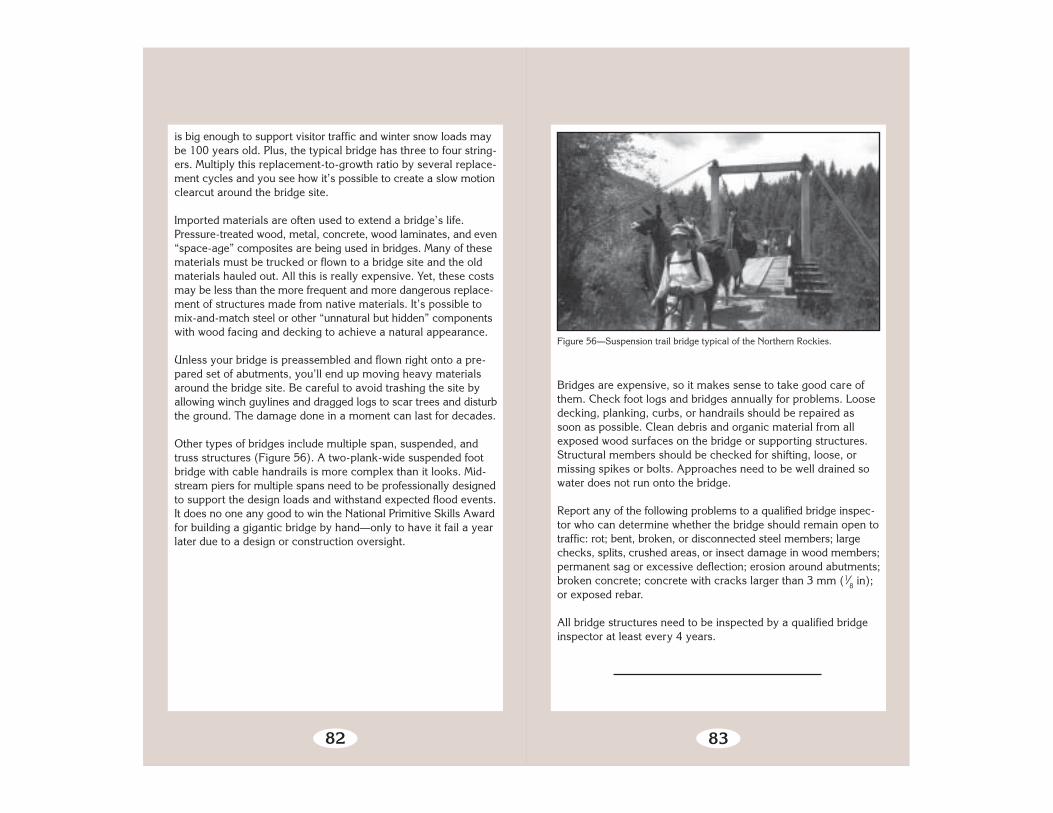
Other types of bridges include multiple span, suspended, andtruss structures (Figure 56). A two-plank-wide suspended footbridge with cable handrails is more complex than it looks. Mid-stream piers for multiple spans need to be professionally designedto support the design loads and withstand expected flood events.It does no one any good to win the National Primitive Skills Awardfor building a gigantic bridge by hand—only to have it fail a yearlater due to a design or construction oversight.
83
Figure 56—Suspension trail bridge typical of the Northern Rockies.
Bridges are expensive, so it makes sense to take good care ofthem. Check foot logs and bridges annually for problems. Loosedecking, planking, curbs, or handrails should be repaired assoon as possible. Clean debris and organic material from allexposed wood surfaces on the bridge or supporting structures.Structural members should be checked for shifting, loose, ormissing spikes or bolts. Approaches need to be well drained sowater does not run onto the bridge.
Report any of the following problems to a qualified bridge inspec-tor who can determine whether the bridge should remain open totraffic: rot; bent, broken, or disconnected steel members; largechecks, splits, crushed areas, or insect damage in wood members;permanent sag or excessive deflection; erosion around abutments;broken concrete; concrete with cracks larger than 3 mm (1⁄8 in);or exposed rebar.
All bridge structures need to be inspected by a qualified bridgeinspector at least every 4 years.
Related Documents