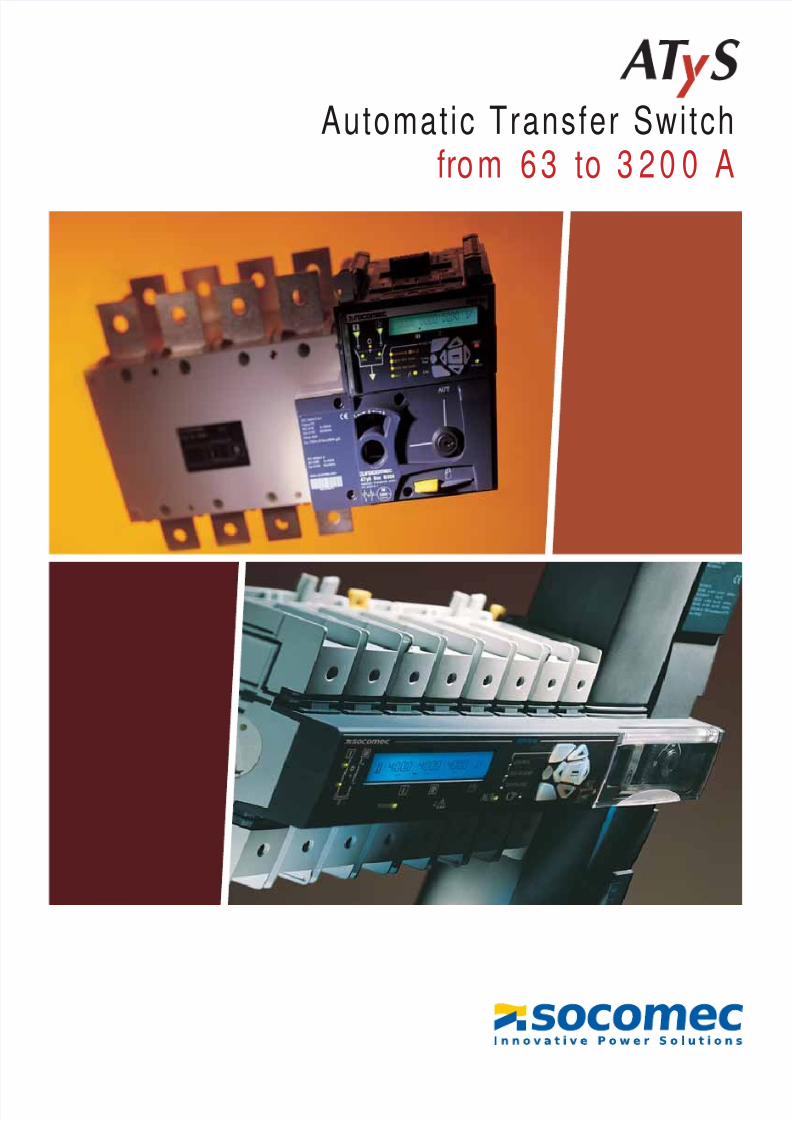
Automatic Transfer Switch f rom 63 to 3200 A

Welcome message from author
This document is posted to help you gain knowledge. Please leave a comment to let me know what you think about it! Share it to your friends and learn new things together.
Transcript
7/29/2019 Socomec ATySM Catalog En
http://slidepdf.com/reader/full/socomec-atysm-catalog-en 1/42
Automatic Transfer Switchfro m 6 3 to 3 2 0 0 A
7/29/2019 Socomec ATySM Catalog En
http://slidepdf.com/reader/full/socomec-atysm-catalog-en 2/42
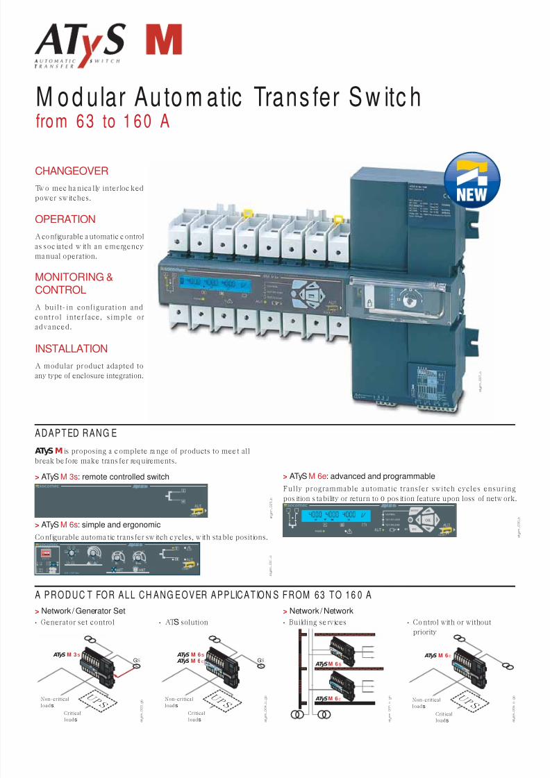
M o d ular Au to m atic Trans fer S w itc hfrom 63 to 1 60 A
CHANGEOVER
Tw o mec ha nica lly interloc ked
power sw itches.
OPERATION
A configurable a utomatic c ontrol
as soc iated w ith an emergency
ma nual operation.
MONITORING &CONTROL
A built-in configuration and
control interface, simple or
advanced.
INSTALLATION
A modular product adapted to
any type of enclosure integration.
a t y s m_
0 0 7_
b
ADAPTED RANG E
> ATyS M 6s: simple and ergonomic
Co nfigurable automa tic trans fer sw itch c ycles, w ith sta ble positions.
> ATyS M 6e: advanced and programmable
Fully programmable automatic transfer switch cycles ensuring
pos ition s ta bility or return to 0 pos ition feature upon loss of netw ork.
a t y s m_
0 3 1_
b
a t y s m
_ 0 3 0_
b
ATySM is proposing a c omplete ra nge of products to mee t all
break be fore make trans fer req uirements.
a t y s m_
0 2 9_
b
> ATyS M 3s: remote controlled switch
A PRODUC T FOR ALL CH ANG EOVER APPLICATION S FROM 63 TO 16 0 A
> Network / Generator Set
• Generator set control
Non-critical
loads
ATyS M 3s
GS
Critical
loads
U P S
• ATS solution
Non-critical
loads
ATyS M 6s
ATyS M 6
eG
S
Critical
loads
U P S
> Network / Network
• Building se rvices
ATySM 6e
ATySM 6s
• Co ntrol with or without
priority
Non-critical
loads
ATyS M 6e
Critical
loads
U P S
a t y s m_
0 0 3_
g b
a t y s m_
0 0 4_
b_
g b
a t y s m_
0 0 5_
b_
g b
a t y s m_
0 0 6_
b_
g b
7/29/2019 Socomec ATySM Catalog En
http://slidepdf.com/reader/full/socomec-atysm-catalog-en 3/42
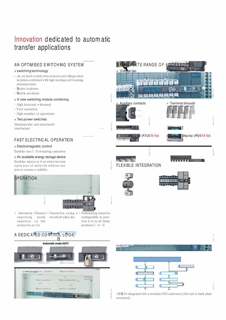
Innovation d ed ic ated to autom atictransfer applications
AN OPTIM ISED S W ITCH ING SYSTEM
> switching technology
• An on loa d s witch disconnector providing s afety
iso la tion combined w ith high ma king a nd b reaking
characteristics
• Sa fety isola tion
• Stab le pos itions
> A new switching module combining
• High dyna mic w ithstand
• Fast operation• High number of operations
> Two power switches
Mechanically and electrically
interlocked SIISI
t a y s m_
0 0 2_
a
a t y s m_
0 3 8_
a
> Bridging bar
A C OM PLETE RANGE O F ACC ESSORIES
a t y s m_
0 1 9_
a
a t y s m_
0 2 7_
a
a t y s m_
0 2 1_
a
a t y s m_
0 3 5_
a
FAST ELECTRIC AL O PERATIO N
> Electromagnetic control
Enab les fas t I - II switching opera tion
> An available energy storage device
Enab les return to 0 po sition fea ture
upon los s o f network without any
pow er source a vaila ble a t y s m_
0 3 7_
a
OPERATION
> Automa tic /Manua l
operat ing modeselection via the
protec tive co ver
> O pera t ion us ing a
sta nda rd a llen key
> Padlocking function
configurable in posi-tion 0 or in all three
positions I - 0 - II
FLEXIBLE INTEGRATION
ATySM integrated into a modular DIN enclosure (Din rail or back plate
mounted).
a p p l i_ 1 8 1_
b
a p p l i_ 1 7 7_
a
Network failure
Automatic mode (AUT)
Generator start
MFT
Network availability
Switch to position 0
Switch to position
Switch to position
Generator stop
Switch to position 0
Semi automatic mode
Network availability
DTT
0MF
MRT
0MR
CDT
no
yes
Manual
operation
Network : priority power source
Network : bac kup powe r source2
1
2
1
2 1
1
Example (generator application):
A DEDIC ATED CO NTROL LO G IC
a t y s_
0 2 8_
c_
g b
a t y s_
5 6 5_
c
> Voltage tap
> Auxiliary contacts > Terminal shrouds
a t y s m_
0 1 4_
a
a t y s m_
0 1 5_
a
a t y s m_
0 1 6_
a
a t y s m_
0 3 5_
a
> Sealable cover (ATyS M 6s) > Remote display (ATyS M 6e)
7/29/2019 Socomec ATySM Catalog En
http://slidepdf.com/reader/full/socomec-atysm-catalog-en 4/42
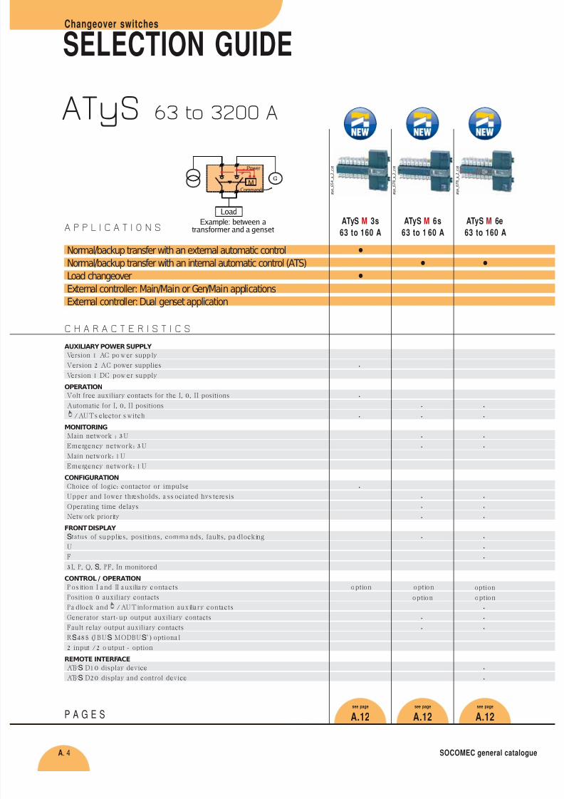
ATyS M 3s ATyS M 6s ATyS M 6e
63 to 160 A 63 to 1 60 A 63 to 160 A
Normal/backup transfer with an external automatic control •Normal/backup transfer with an internal automatic control (ATS) • •Load changeover •External controller: Main/Main or Gen/Main applicationsExternal controller:Dual genset application
AUXILIARY POWER SUPPLY
Version 1 AC po w er supp ly
Version 2 AC power supplies •
Version 1 DC pow er supply
OPERATION
Volt free auxiliary contacts for the I, 0, II positions •
Automatic for I, 0, II positions • •/AUTs elector s witch • • •
MONITORING
Main network : 3U • •
Emergency network: 3U • •
Main network: 1U
Emergency network: 1U
CONFIGURATION
Choice of logic: contactor or impulse •
Upper and lower thresholds, a ss ociated hys teresis • •
Operating time delays • •
Netw ork priority • •
FRONT DISPLAY
Status of supplies, positions, comma nds, faults, pa dlocking • •
U •
F •
3I, P, Q, S, PF, In monitored
CONTROL / OPERATION
P os ition I a nd II a uxilia ry conta cts option option option
Position 0 auxiliary contacts option option
Pa dlock and /AUTinformation auxiliary contacts •
Generator start-up output auxiliary contacts • •
Fault relay output auxiliary contacts • •
RS485 (J BUS MODBUS® ) optiona l
2 input /2 o utput - option
REMOTE INTERFACE
ATyS D10 display device •
ATyS
D20 display and control device •
SOCOMEC general catalogueA. 4
SELECTION GUIDE
ATyS 63 to 3200 A
A P P L I C A T I O N S
a t y s
_ 6 7 8
_ a
_ 2
_ c a
t
a t y s
_ 6 7 8
_ a
_ 2
_ c a
tPower
Command
Load
M
Example: between atransformer and a genset
see page
A.12see page
A.12see page
A.12
C H A R A C T E R I S T I C S
P A G E S
Changeover switches
a t y s
_ 6 5 4
_ a
_ 2
_ c a
t
7/29/2019 Socomec ATySM Catalog En
http://slidepdf.com/reader/full/socomec-atysm-catalog-en 5/42SOCOM EC general catalogue A. 5
a t y s
_ 0 0 3
_ a
_ 3
_ c a
t
a t y s
_ 1 0 3
_ a
_ 1
_ c a
t
a t y s
_ 0 9 7
_ b
_ 2
_ c a
t
a t y s
_ 1 0 2
_ a
_ 2
_ c a
t
a t y s
_ 4 4 8
_ b
_ 2
_ c a
t
a t y s
_ 5 9 9
_ b
_ 2
_ c a
t
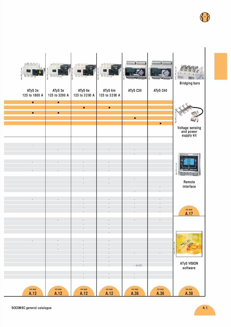
ATyS 3s ATyS 3e ATyS 6e ATyS 6m ATyS C30 ATyS C40
125 to 1800 A 125 to 3200 A 125 to 3 2 00 A 125 to 3 2 00 A
• •• •
• ••
•
•
• • • •
• •
• • • •
• •• • • •
• • •
• •
•
• •
• • • • • •
• • • •
• • • •
• • • •
• • • • •
• •
• •
•
• • • •
• • •
• • •
• • • •
• •
• •
• • • (s td)
• • •
• • •
a c c e s
_ 2 0 5
_ a
_ 1
_ c a
t
Bridging bars
a t y s
_ 6 0 6
_ a
_ 2
_ c a t
Voltage sensingand powersupply kit
see page
A.38see page
A.36see page
A.36see page
A.12see page
A.12see page
A.12see page
A.12
see page
A.17
Remoteinterface
a t y s
_ 5 6 5
_ c_
2_
c a
t
ATyS VISIONsoftware
c o u v
_ 1 2 8
_ a
_ 2
_ c a
t
7/29/2019 Socomec ATySM Catalog En
http://slidepdf.com/reader/full/socomec-atysm-catalog-en 6/42A. 6
Changeover switches
The ATyS range
SOCOMEC general catalogue
The ATyS remote controlled and automatic transfer switch familyproposes a complete range of low voltage compact changeover
switches a nd acc essories.
The new ATyS M family ded ica ted to applica tions below 160 A
keeps key features a nd c haracteristics o f the existing ATySproduct range bringing some innovation.
ATyS range is now also ava ilab le up to 3200A to c omplete the
family for higher c urrent a pplica tions.
ATyS are compo sed of two mecha nica lly a nd electrica lly
interlocked switches.
All the produc ts a re fitted with emergency manual operation.
• either remotely controlled: ATyS M 3 and ATyS 3 products are
driven by volt-free d ry conta cts allow ing sw itching o perationbetw een po sition I, 0 or II, from a n external co ntrol log ic or a p lc
(co ntro l rela ys typ e ATyS C30).
• or automaticaly controlled: ATyS M 6 and ATyS 6 are
dedicated to break before make automa tic transfer applica tions.
They integrate c ontrol relays , timers a nd tes t functions to
mana ge a Normal/Ba ckup switching ope ration betw een 2
networks or a Generator set and a network.
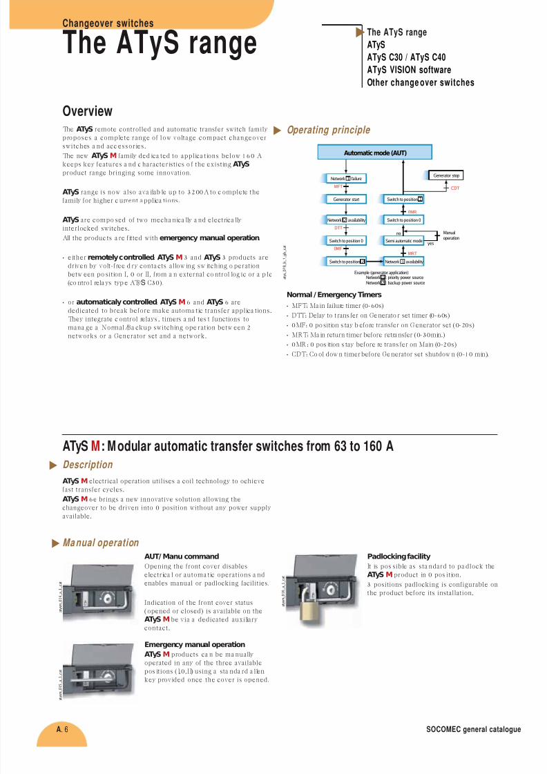
Overview
Operating principle L
Network failure
Automatic mode (AUT)
Generator start
MFT
Network availability
Switch to position 0
Switch to position
Switch to position
Generator stop
Switch to position 0
Semi automatic mode
Network availability
DTT
0MFMRT
0MR
CDT
no
yes
Manualoperation
Network : priority power sourceNetwork : backup power source2
1
2
1
2 1
1
Example (generator application): a
t y s
_ 0 2 8_
b_
1_
g b
_ c a
t
Normal / Emergency Timers
• MFT: Main failure timer (0-60s)
• DTT: Delay to t rans fer on Generato r set timer (0-60s)
• 0MF: 0 po sition s tay b efore transfer on G enerator set (0-20s)
• MRT: Ma in return timer before retransfer (0-30min.)
• 0MR : 0 pos ition s tay before re trans fer on Main (0-20s)
• CDT: Co ol dow n timer before Ge nerator set shutdow n (0-10 min).
AUT/ Manu command
Opening the front cover disables
electrica l or automa tic operations a nd
enables manual or padlocking facilities.
Indication of the front cover status
(opened or closed) is available on the
ATyS M be via a dedicated auxiliary
contact.
Padlocking facility
It is pos sible as sta ndard to pa dlock the
ATyS M product in 0 pos ition.
3 positions padlocking is configurable on
the product before its installation.
a t y s m
_ 0 1 6
_ a
_ 1
_ c a
t
a t y s m
_ 0 1 4
_ a
_ 1
_ c a
t
Ma nual operation L
Emergency manual operation
ATyS M products ca n be ma nually
operated in any of the three available
pos itions (I,0,II) using a sta nda rd a llen
key provided once the cover is opened.
a t y s m
_ 0 1 5
_ a
_ 1
_ c a
t
Description L
ATyS M: Modular automatic transfer switches from 63 to 160 A
ATyS M electrical operation utilises a coil technology to ochieve
fast transfer cycles.
ATyS M 6e brings a new innovative solution allowing the
changeover to be driven into 0 position without any power supply
available.
LThe ATyS range
ATyS
ATyS C30 / ATyS C40
ATyS VISION software
Other change over switches
7/29/2019 Socomec ATySM Catalog En
http://slidepdf.com/reader/full/socomec-atysm-catalog-en 7/42A. 7
Changeover switches
The ATyS range
SOCOM EC general ca talogue
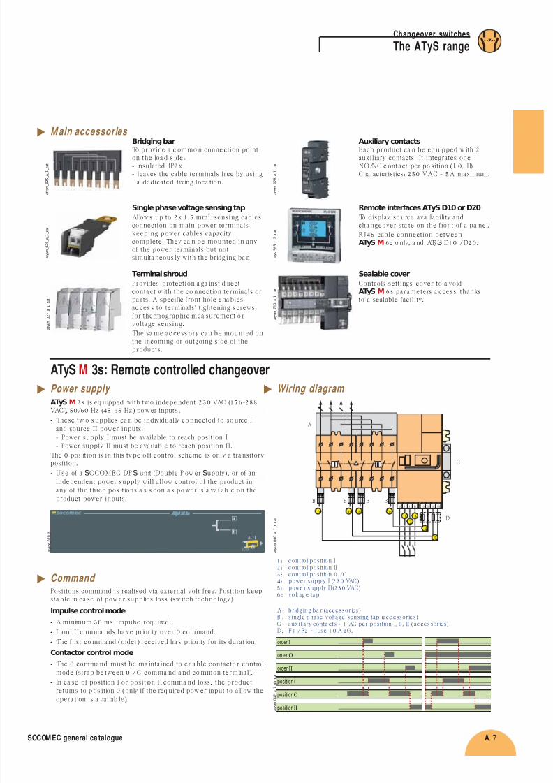
Power supply L
Command L
ATyS M 3s: Remote controlled changeover
Positions command is realised via external volt free. Position keepsta ble in ca se of pow er supplies loss (sw itch technology).
Impulse control mode
• A minimum 30 ms impulse required.
• I and II comma nds ha ve priority over 0 command.
• The first co mma nd (order) received ha s priority for its durat ion.
Contactor control mode
• The 0 command must be ma intained to ena ble contacto r controlmode (strap be tween 0 /C comma nd a nd co mmon terminal).
• In ca se of position I or position II comma nd loss, the product
returns to p os ition 0 (only if the req uired pow er input to a llow the
opera tion is a vailab le).
ATyS M 3s is eq uipped with tw o indepe ndent 230 VAC (176-288VAC ), 50/60 Hz (45-65 Hz ) po w er inputs .
• These tw o s upplies ca n be individually co nnected to so urce I
and source II power inputs:
- Power supply I must be available to reach position I
- Power supply II must be available to reach position II.
The 0 pos ition is in this ty pe o ff control scheme is only a tra nsitoryposition.
• Use of a SOCOMEC DPS unit (Double P ow er Supply), or of an
independent power supply will allow control of the product in
any of the three pos itions a s s oon a s po wer is a vailab le on the
product power inputs.
Wiring diagram L
1: control posit ion I2: control posit ion II3: control posit ion 0 /C4: power supply I (230 VAC)5: powe r supply II (230 VAC)6 : vo lt ag e ta p
A: bridging ba r (accessor ies)B : single phase voltage sensing tap (acc essories)C : auxiliary conta cts - 1 AC per position I, 0, II ( ac ces sories)D: F1 /F2 = fuse 10 A gG.
101102201202313314315317
A
BBBB
C
3
4
5
6 6 6 6
21 D
a t y s m
_ 0 4 0_ a
_ 1
_ x_ c a
t
a t y s m
_ 0 2 9_
b
order I
order O
order II
position I
positionO
position II a t y s m
_ 0 4 2
_ a
_ 1
_ g
b_
c a
t
a t y s m
_ 0 2 5
_ a
_ 1
_ c a
t
Bridging barTo provide a c ommo n conne ction pointon the loa d s ide:- insulated IP2x- leaves the cable terminals free by using
a dedicated fixing loca tion.
a t y s m
_ 0 2 6
_ a
_ 1
_ c a
t
Single phase voltage sensing tap
Allow s up to 2x 1,5 mm2. sensing cablesconnection on main power terminalskeeping power cables capacitycomplete. They ca n be mounted in anyof the power terminals but notsimulta neous ly with the bridg ing ba r.
a t y s m
_ 0 2 7
_ a
_ 1
_ c a
t
Terminal shroud
Provides protection a ga inst d irectconta ct w ith the co nnection terminals orpa rts. A specific front hole ena blesac ces s to terminals’ tightening s crewsfor thermographic mea surement o rvoltage sensing.
The sa me ac cess ory can be mounted onthe incoming or outgoing side of theproducts.
M ain accessories L
a t y s m
_ 0 2 8
_ a
_ 1
_ c a
t
Auxiliary contactsEach product ca n be eq uipped w ith 2auxiliary contacts. It integrates oneNO/NC c ont a ct per po sition (I, 0, II).Characteristics: 250 VAC - 5A maximum.
a t y s
_ 5 6 5
_ c
_ 2
_ c a
t
Remote interfaces ATyS D10 or D20
To display so urce ava ilability andcha ngeover sta te on the front of a pa nel.
RJ45 cable connection betweenATyS M 6e o nly, a nd ATyS D10 /D20.
a t y s m
_ 7 1 0
_ a
_ 1
_ c a
t
Sealable cover
Controls settings cover to a voidATyS M 6s parameters a ccess thanksto a sealable facility.
7/29/2019 Socomec ATySM Catalog En
http://slidepdf.com/reader/full/socomec-atysm-catalog-en 8/42A. 8
Changeover switches
The ATyS range
SOCOMEC general catalogue
ATyS M 6: Automatic Transfer Sw itch
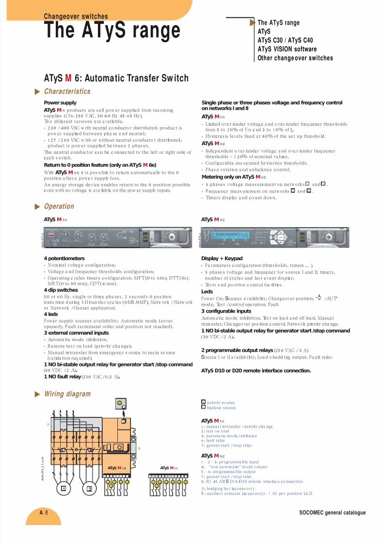
Wiring diagram L
210209208207 74736463
A
B
ATyS M 6s ATyS M 6e
312
76
210209208207 54534443
312
54
74736463
76
RJ
8
1 2
priority so urcebackup source
ATyS M 6s1: manua l retransfer /priority cha nge2: test on load3: automa tic mo de inhibition6: fault relay7: genset start /stop relay
ATyS M 6e
1 - 2 - 3: programma ble input4 : “non au tomatic ” mode output5 - 6: programma ble output7: genset start /stop relay8 : RJ 45 ATyS D10/D20 remote interfac e co nnec tion
A: bridging ba r (ac cess ory)B : auxilia ry conta cts (ac ces so ry) - 1 AC pe r position I,0,II.
2
1
a t y s m
_ 0 4 1
_ a
_ 1_
x_ c a
t
4 potentiometers
• Nominal voltag e configuration;
• Voltag e a nd frequency thresholds configuration;
• Operating c ycles timers co nfiguration: MFT(0 to 60s), DTT(5s),MRT(0 to 30 min), CDT(4 min).
4 dip switches
50 or 60 Hz, s ingle or three pha ses , 2 s econd s 0 pos itiontrans ition d uring I-II tran sfe r cyc les (0MR/0MF), Netw ork /Netw orkor Network /Genset application.
4 leds
Power supply sources availability; Automatic mode (coveropened); Fault (command order and position not reached).
3 external command inputs
• Automa tic mode inhibition;
• Remote tes t on load (priority cha nge);
• Manual retransfer from emergency s ource to ma in so urce(va lida tion req uired ).
1 NO bi-stable output relay for generator start /stop command
(30 VDC /2 A).1 NO fault relay (250 VAC /0,5 A).
ATyS M 6s ATyS M 6e
Operation L
a t y s m
_ 0 1 7
_ a
Display + Keypad
• Pa rameters configuration (thresholds, timers … );
• 3 phase s voltage and frequency for source I and II, timers,
number of cycles and las t event display;• Tes ts a nd po sition c ontrol fac ilities .
Leds
Power On; Sources a vailability; Chang eover position; “ /AUT”
mod e; Tes t /cont rol ope ration; Fault.
3 configurable inputs
Autom a tic mo de inhibition; Tes t on loa d a nd off loa d; Manua l
retra nsfer; Cha ngeo ver pos ition c ontrol; Netwo rk priority cha nge.
1 NO bi-stable output relay for generator start /stop command(30 VDC /2 A).
2 programmable output relays (250 VAC / 3 A)
Source I or II a vailab ility; Loa d s hedd ing output; Fa ult relay.
ATyS D10 or D20 remote interface connection.
a t y s m
_ 0 1 8
_ a
Characteristics L
Power supply
ATyS M 6 products are s elf pow er supplied from incomingsupp lies (176-288 VAC , 50/60 Hz 45-65 Hz ).Two different versions a re a vaila ble:
• 230 /400 VAC w ith neutral co nducto r distributed: produc t ispow er supplied b etween pha se a nd neutral;
• 127 /230 VAC w ith or without neutral co nducto r distributed :product is pow er supplied be tween 2 phas es.
The neutral conduc tor ca n be c onnec ted to the left or right side ofeach s witch.
Return to 0 position feature (only on ATyS M6e)
With ATyS M 6e it is pos sible to return a utomatically to the 0position a fter a powe r supply loss.
An energy storage device enables return to the 0 position possibleeven with no voltage is ava ilab le o n the pow er supply inputs.
Single phase or three phases voltage and frequency controlon networks I and II
ATyS M6s
• Linked ove r/under voltag e a nd o ver/under freq uency thres holdsfrom 5 to 20% of Un a nd 3 to 10% of fn.
• Hysteres is levels fixed a t 80% of the se t up thresho ld.
ATyS M6e
• Indep endent o ver/under voltage a nd ove r/under freq uencythresholds + /-20% of nominal va lues.
• Configurable ass ociated hysterisis thresholds.
• Phas e rotation a nd unbalance control.
Metering only on ATyS M6e
• 3 phases voltage measurement on networks and .• Frequency meas urement on networks and .
• Timers display a nd co unt down.
21
21
LThe ATyS range
ATyS
ATyS C30 / ATyS C40
ATyS VISION software
Other change over switches
7/29/2019 Socomec ATySM Catalog En
http://slidepdf.com/reader/full/socomec-atysm-catalog-en 9/42A. 9
Changeover switches
The ATyS range
SOCOM EC general ca talogue
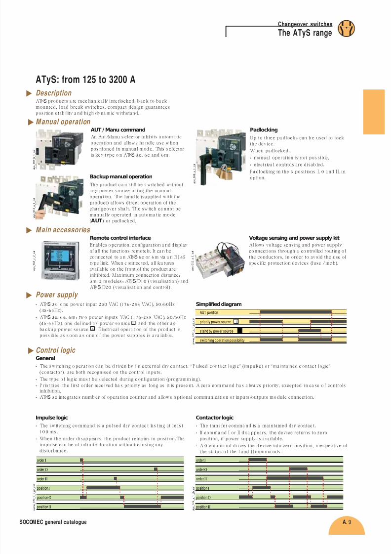
ATyS: from 125 to 3200 A
Description L
Power supply L
ATyS products a re mec hanically interlocked, b ac k to ba ck
mounted, load break switches, compact design guarantees
position s tab ility a nd high dyna mic withstand.
Simplified diagram• ATyS 3s : o ne po w er input 230 VAC (176-288 VAC ), 50/60Hz
(45-65Hz).
• ATyS 3e, 6e, 6m : tw o pow er inputs VAC (176-288 VAC ), 50/60Hz
(45-65Hz), one defined a s pow er so urce and the other a s
ba ckup pow er so urce . Electrical opera tion of the product is
poss ible as s oon a s one o f the power supplies is ava ilab le.
2
1
AUT position
priority power source
stand by power source
switching operation possibility
1
2
s v r m o
_ 0 7 7
_ c
_ 1
_ g
b_
c a
t
Padlocking
Up to three pa dlocks can b e used to lock
the device.
When padlocked:
• manual operation is not pos sible,
• electrica l controls are disab led.
P a dlocking in the 3 po sitions I, 0 a nd II, in
option. a
t y s
_ 0 0 8
_ a
_ 1
_ c a
t
Backup manual operation
The product c a n still be s witched without
any pow er source using the manualopera tion. The hand le (supplied with the
product) allows direct operation of the
cha ngeover shaft. The sw itch ca nnot be
manually operated in automa tic mo de
(AUT) or padlocked. a
t y s
_ 0 1 3
_ a
_ 1
_ c a
t
General
• The s witching o peration c an be d riven by a n external dry co ntact. “P ulsed conta ct logic” (impulse) or “maintained c ontac t logic”
(contactor), are both recognised on the control inputs.
• The type o f log ic mus t be s elected during c onfiguration (programm ing).• P riorities: the first order rece ived ha s priority as long as it is prese nt. A zero com ma nd ha s a lwa ys priority, excepted in ca se o f controls
inhibition.
• ATyS 3e integrate s numb er of operation counter and allow s o ptional communication or inputs/outputs mo dule connection.
Impulse logic
• The sw itching co mmand is a pulsed dry contac t las ting at leas t
100 ms.
• When the order disap pea rs, the product rema ins in position.The
impulse can be of infinite duration without causing any
disturbance.
Contactor logic
• The trans fer comma nd is a maintained dry contac t.
• If comma nd I or II disa ppears, the device returns to ze ro
position, if power supply is available.
• A 0 comma nd drives the d evice into zero pos ition, irres pec tive of
the status o f the I and II comma nds.
order I
order O
order II
position I
positionO
position II s v r m o
_ 0 7 9
_ b
_ 1
_ g
b_
c a
t
order I
order O
order II
position I
positionO
position II a
t y s
_ 0 2 4
_ a
_ 1
_ g
b_
c a
t
Control logic L
AUT / Manu command
An Aut/Manu s elect or inhibits a utom a tic
operation and allow s ha ndle use w hen
pos itioned in manua l mod e. This s elector
is key t ype o n ATyS 3e, 6e and 6m.
a t y s
_ 0 9 7
_ b
_ 1
_ c a
t
M anual operation L
M ain accessories L
a t y s
_ 5 6 5
_ c
_ 2
_ c a
t
Remote control interface
Enables o peration, c onfiguration a nd d isplay
of a ll the functions remotely. It ca n be
co nnec ted to a n ATyS 6e or 6m via a n RJ 45
type link. When c onnec ted, a ll fea tures
available on the front of the product are
inhibited. Maximum connection distance:
3m. 2 mod eles : ATyS
D10 (visualisation) andATyS D20 (visualisation and control).
a t y s
_ 0 1 1
_ a
_ 1
_ c a
t
Voltage sensing and power supply kit
Allows voltage sensing and power supply
co nnections through a co ntrolled routing o f
the conductors, in order to avoid the use of
spe cific protection devices (fuse /mc b).
7/29/2019 Socomec ATySM Catalog En
http://slidepdf.com/reader/full/socomec-atysm-catalog-en 10/42A. 10
Changeover switches
The ATyS range
SOCOMEC general catalogue
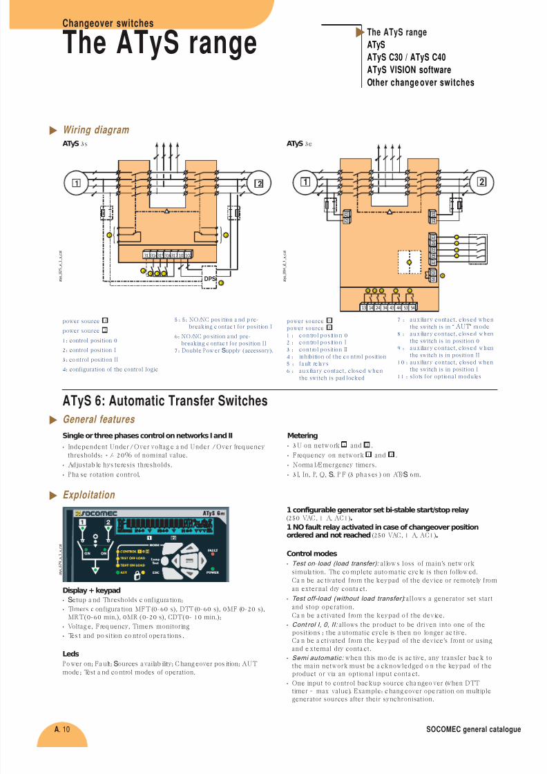
Wiring diagram L
power source
power source
1: control position 0
2: control position I
3: co ntrol position II
4: configuration of the control logic
5 : 5: NO/NC pos ition a nd p re-breaking c ontac t for position I
6: NO/NC po sition a nd pre-breaking c ontac t for position II
7: Double Pow er Supply (accessory).
2
1
5 6
43 2 1
313314315316317
1 2
101102
DPS7
a t y s
_ 0 2 5
_ e_
1_
x_
c a
t
power sourcepower source1 : contro l pos it ion 02 : contro l pos it ion I3 : control posit ion II4 : inhibition of the co ntrol position5 : f ault re lay s6 : auxiliary contact , c losed when
the switch is pad locked
7 : auxiliary contact , c losed whenthe switch is in “ AUT” mode
8 : auxiliary contact , c losed whenthe switch is in position 0
9 : auxiliary contact , c losed whenthe switch is in position II
10 : auxiliary contact, closed whenthe switch is in position I
11 : slots for optional modules
2
1
5
6710 9 8
21
13 14 24 34 43 44 53 54
6 4
6 3
1 0 2
2 0 2 2 0 1
1 0 1
3 1 7 3 1 6 3 1 5
3 1 3
3 1 4
11
4
3
2
1
a t y s
_ 0 9 4
_ d_
1_
x_
c a
t
ATyS 6: Automatic Transfer Switches
Display + keypad
• Setup a nd Thresholds c onfigura tion;
• Timers c on figura tion MFT (0-60 s), DTT(0-60 s), 0MF (0-20 s),MRT(0-60 min.), 0MR (0-20 s), CDT(0- 10 min.);
• Voltag e, Freq uency, Timers monitoring
• Tes t and po sition co ntrol opera tions .
Leds
Po wer on; Fa ult; Sources a vailab ility; C hang eover pos ition; AUT
mode ; Test a nd co ntrol modes of operation.
1 configurable generator set bi-stable start/stop relay(250 VAC , 1 A, AC1).
1 NO fault relay activated in case of changeover positionordered and not reached (250 VAC , 1 A, AC1).
Control modes
• Test on -load (load transfer): allow s loss of main’s netw ork
simula tion. The co mplete auto ma tic cyc le is then follow ed.
Ca n be ac tivated from the keypad of the device or remotely from
an external dry conta ct.
• Test off-load (without load transfer): allows a generator set start
and stop operation.
Ca n be a ctivated from the keypad o f the device.
• Cont rol I, 0, II: allows the product to be driven into one of thepositions ; the a utomatic cycle is then no longer ac tive.Ca n be a ctivated from the keypad of the device’s front or usingand e xternal dry conta ct.
• Semi automatic: when this mo de is ac tive, any transfer bac k tothe main network must be a cknowledged o n the keypad of theproduct or via an optional input conta ct.
• One input to control bac kup source cha ngeo ver (when DTTtimer = max value). Example: c hang eover ope ration on multiplegenerator sources after their synchronisation.
Exploitation L
a t y s
_ 6 7 9
_ a
_ 1
_ x_ c a
t
General features L
Single or three phases control on networks I and II
• Independent Under/Over voltag e a nd Under /Over freq uency
thresholds: + /- 20% of nominal value.
• Adjustab le hys teresis thresholds.
• Pha se rotation control.
Metering
• 3U on network and .
• Frequency on network and .
• Norma l/Emergency timers.
• 3I, In, P, Q, S, P F (3 pha s es ) on ATyS 6m.
21
21
ATyS 3s ATyS 3e
LThe ATyS range
ATyS
ATyS C30 / ATyS C40
ATyS VISION software
Other change over switches
7/29/2019 Socomec ATySM Catalog En
http://slidepdf.com/reader/full/socomec-atysm-catalog-en 11/42A. 11
Changeover switches
The ATyS range
SOCOM EC general ca talogue
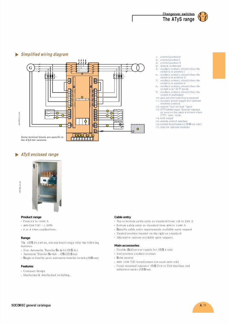
ATyS enclosed range L
Product range
• From 63 to 1600 A• 400/230 VAC + /- 20%
• 3 or 4 wires a pplica tions.
Range
The ATyS 3s a nd 6e, 6m enc lose d rang e offer the follow ing
features:
• Non-Automa tic Trans fer Sw itc h (ATyS 3s )
• Automa tic Trans fer Switch - ATS (ATyS 6e)
• Single or d ual by-pa ss auto ma tic trans fer sw itch (ATyS 6m)
Features
• Compact design
• Mecha nica lly interloc ked sw itching.
Cable entry
• Top or bo ttom ca ble entry a s s tanda rd from 125 to 250 A• Bottom c ab le entry as sta ndard from 400 to 1600 A
• Specific cable entry requirements available upon request
• Neutral position located on the right a s s tanda rd
• Alternative options ava ila ble upon reques t.
Main accessories
• Double (Self) po w er s upply for ATyS 3 only
• 2nd position a uxiliary co ntact
• Solid neutral
• 400 /230 VAC tra nsformers (on ea ch netw ork)
• P a nel mounted o perato r ATyS D10 or D20 interface and
indica tion me te r (ATyS 6e).
c o
f f_ 3 0 6
_ a
_ 2
_ c a
t
Simplified wiring diagram L
7 3
2 1 0
2 0 9
2 0 8
2 0 7
2 0 6
2 0 5
2 0 4
2 0 3
2 0 2
2 0 1
7 4
P o w e r 2 3 0 V A C
2
P ow e r 2 3 0 VA C
F1F2
13
5 6 7 8 9
1211
10
4
16
3
21
14
1
15
13 14 243443 445354
1 0 1
1 0 2
1 0 3
1 0 4
1 0 5
1 0 6
3 1 3
3 1 4
3 1 5
3 1 6
3 1 7
6 3
6 4
R J
V ol t a g e s en s i n g
L 1
L 2
L 3
N
V o l t a g e s e n s i n g
L 1
L 2
L 3
N
17
1: control posit ion 02: control posit ion I3: control posit ion II4 : re mo te co mm a nd5: auxiliary contact , c losed when the
switch is in position I6: auxiliary contact , c losed when the
switch is in position II7: auxiliary contact , c losed when the
switch is in position 08: auxiliary contact , c losed when the
sw itch is in “AUT” mo de9: auxiliary contact , c losed when the
switch is padlocked10: gen-set s tar t and s top command11: auxiliary power supply (for optional
modules control)12: remote “test on-load ”input
13: DTTinhibit input. Trans fer initiatedas soon a s the input is closed w henDTT= max. va lue.
14: fault output15: remote control interface16: c urrent tra ns forme rs (ATyS 6m only)17: slots for optional modules
a t y s
_ 0 2 6
_ d
_ 1
_ x
_ c a
t
Some terminal blocks are specific to
the ATyS 6m versions.
7/29/2019 Socomec ATySM Catalog En
http://slidepdf.com/reader/full/socomec-atysm-catalog-en 12/42A. 12
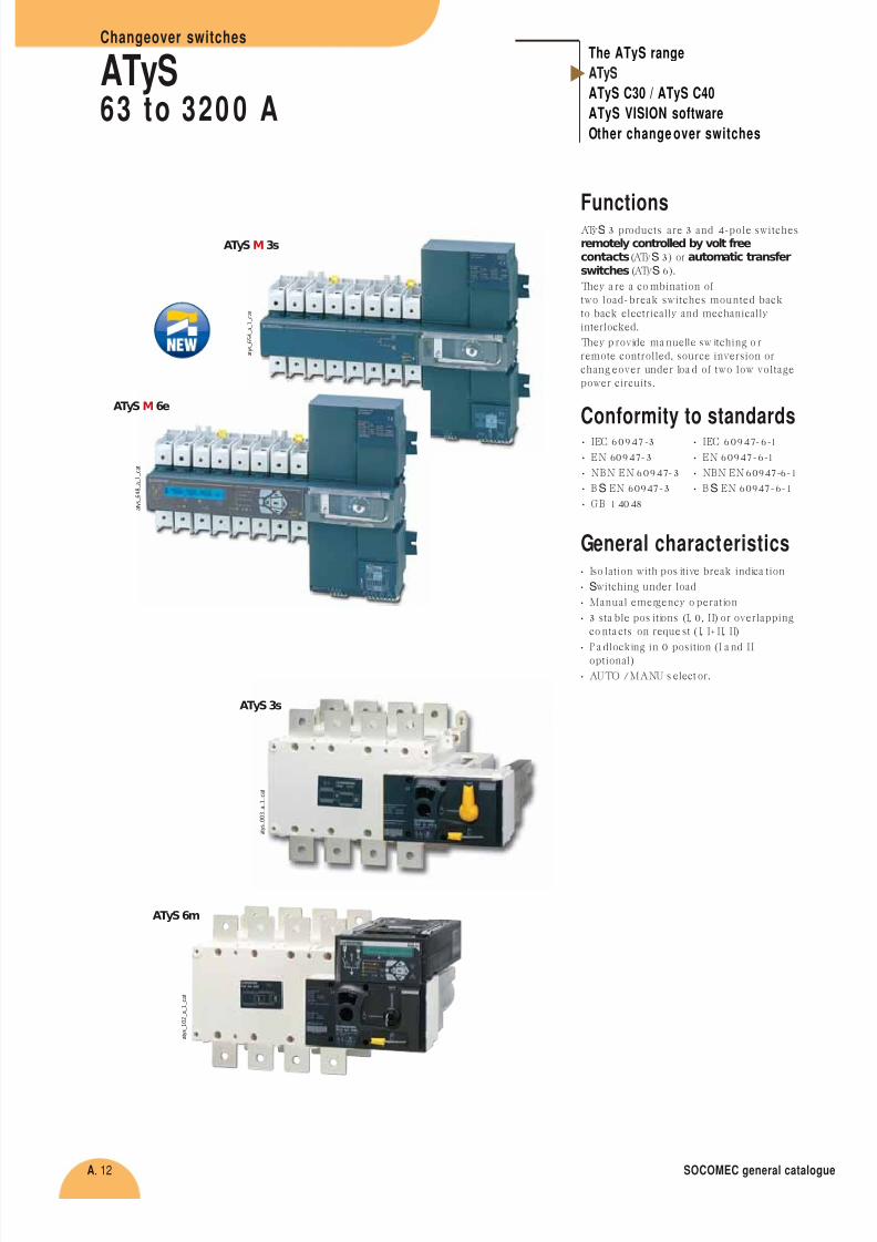
FunctionsATyS 3 products are 3 and 4-pole switches
remotely controlled by volt freecontacts (ATyS 3) or automatic transferswitches (ATyS 6).
They a re a co mbination of
two load-break switches mounted back
to back electrically and mechanically
interlocked.
They p rovide ma nuelle sw itching o r
remote controlled, source inversion or
chang eover under loa d of two low voltage
power circuits.
Conformity to standards
General characteristics• Iso lation with pos itive break indica tion
• Switching under load
• Manual emergency o peration
• 3 sta ble pos itions (I, 0, II) or overlapping
co nta cts on reque st (I, I+ II, II)• P a dlocking in 0 position (I a nd II
optional)
• AUTO /MANU s elect or.
LThe ATyS range
ATyS
ATyS C30 / ATyS C40
ATyS VISION software
Other change over switches
Changeover switches
ATyS63 to 320 0 A
SOCOMEC general catalogue
a t y s
_ 0 0 3
_ a
_ 1
_ c a
t
ATyS 3s
a t y s
_ 1 0 2
_ a
_ 1
_ c a
t
ATyS 6m
• IEC 60947-3
• EN 60947-3
• NBN EN 60947-3
• BS EN 60947-3
• GB 14048
• IEC 60947-6-1
• EN 60947-6-1
• NBN EN 60947-6-1
• BS EN 60947-6-1
ATyS M3s
ATyS M6e
a t y s
_ 6 5 4
_ a
_ 1
_ c a
t
a t y s
_ 6 4 8
_ a
_ 1
_ c a
t
7/29/2019 Socomec ATySM Catalog En
http://slidepdf.com/reader/full/socomec-atysm-catalog-en 13/42A. 13
Changeover switches
ATyS
SOCOM EC general ca talogue
1
2
3
4
5
6
7
8
9
9
10
11
12
13
a t y s
_ 6 1 5
_ a
_ 1
_ x_ c a
t
a t y s m
_ 0 3 2
_ a
_ 1
_ x_ c a
t
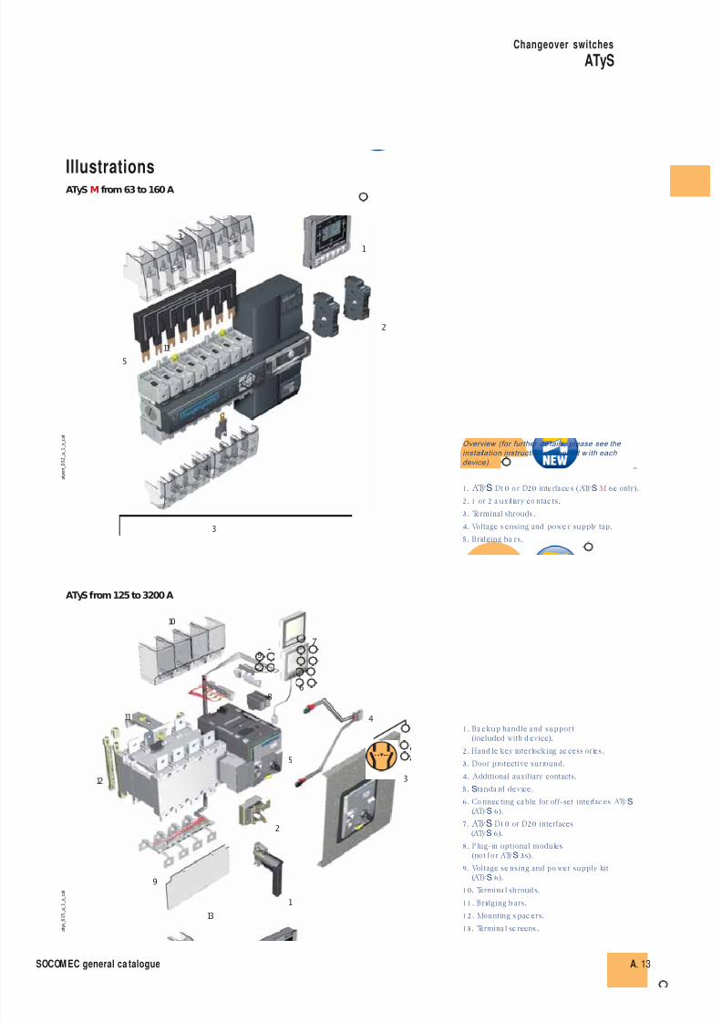
1. Ba ckup handle and support(included with d evice).
2. Hand le key interlocking ac cess ories.
3. Door protective surround.
4. Additional auxiliary contacts.
5. Standa rd device.
6. Co nnec ting ca ble for off-set interfac es ATyS(ATyS 6).
7. ATyS D10 or D20 interfaces(ATyS 6).
8. P lug-in optional modules(no t for ATyS 3s).
9. Voltage se nsing and po wer supply kit(ATyS 6).
10. Termina l sh roud s.
11. Bridging b ars.
12. Mounting s pac ers.
13. Termina l sc reens .
Overview (for further de tails, please see the
installation instructions supplied w ith each
device).
IllustrationsATyS Mfrom 63 to 160 A
ATyS from 125 to 3200 A
1
2
3
3
4
511
1. ATyS D10 o r D20 inte rfa ce s (ATyS M 6e only).
2. 1 or 2 a uxiliary co ntac ts.
3. Terminal shrouds .
4. Voltage s ensing and powe r supply tap.
5. Bridging ba rs.
7/29/2019 Socomec ATySM Catalog En
http://slidepdf.com/reader/full/socomec-atysm-catalog-en 14/42A. 14
L
References
Changeover switches
ATyS63 to 320 0 A
SOCOMEC general catalogue
The ATyS range
ATyS
ATyS C30 / ATyS C40
ATyS VISION software
Other change over switches
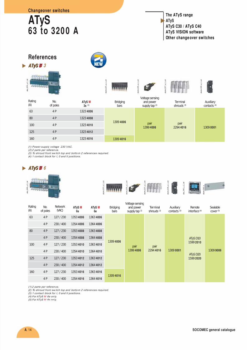
(1) Power-supply voltage 230 VAC.
(2) 2 parts per referen ce.
(3) To shroud front sw itch top and botto m 2 references required.
(4) 1 contact block for I, 0 and II positions.
a t y s
_ 6 5 4
_ a
_ 2
_ c a
t
LATyS 3 ATyS M 3
pair1399 4006
63
Rating(A)
No.of poles
ATyS M3s (1)
1309 4006
1309 4016
Bridgingbars
4 P 1323 4006
80 4 P 1323 4008pair
2294 4016 1309 0001
Voltage sensingand power
supply tap (2)
Terminalshrouds (3)
Auxiliarycontacts (4)
100 4 P 1323 4010
125 4 P 1323 4012
160 4 P 1323 4016
a t y s m
_ 0 2 6
_ a
_ 1
_ c a
t
a t y s m
_ 0 2 7
_ a
_ 1
_ c a
t
a t y s m
_ 0 2 8
_ a
_ 1
_ c a
t
(1) 2 parts per referen ce.
(2) To shroud front sw itch top and botto m 2 references required.
(3) 1 contact block for I, 0 and II positions.
(4) For ATyS M 6e on ly.
(5) For ATyS M 6s on ly.
a t y s
_ 6 4 8
_ a
_ 2
_ c a
t
a t y s m
_ 0 2 5
_ a
_ 1
_ c a
t
LATyS 3 ATyS M 6
pair1399 4006
63
Rating(A)
No.of poles
Network(VAC)
1309 4006
1309 4016
Bridgingbars
4 P 127 / 230
4 P 230 / 400
80 4 P 127 / 230
pair2294 4016 1309 0001
Voltage sensingand power
supply tap (1)
Terminalshrouds (2)
Auxiliarycontacts (3)
ATyS D101599 2010
ATyS D201599 2020
Remoteinterface (4)
1309 9006
Sealablecover (5)
ATyS M6s
1353 4006
1354 4006
1353 4008
ATyS M6e
1363 4006
1364 4006
1363 4008
4 P 230 / 400
100 4 P 127 / 230
4 P 230 / 400
1354 4008
1353 4010
1354 4010
1364 4008
1363 4010
1364 4010
125 4 P 127 / 230
4 P 230 / 400
160 4 P 127 / 230
4 P 230 / 400
1353 4012
1354 4012
1353 4016
1354 4016
1363 4012
1364 4012
1363 4016
1364 4016
a t y s m
_ 0 2 6
_ a
_ 1
_ c a
t
a t y s m
_ 0 2 7
_ a
_ 1
_ c a
t
a t y s m
_ 0 2 8
_ a
_ 1
_ c a
t
a t y s
_ 5 6 5
_ c
_ 2
_ c a
t
a t y s m
_ 0 4 3
_ a
a t y s m
_ 0 2 5
_ a
_ 1
_ c a
t
7/29/2019 Socomec ATySM Catalog En
http://slidepdf.com/reader/full/socomec-atysm-catalog-en 15/42A. 15
Changeover switches
ATyS
SOCOM EC general ca talogue
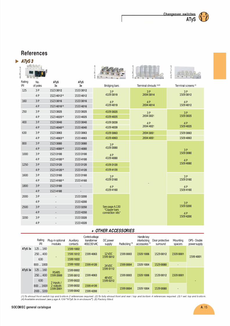
(1) To shroud fro nt switch t op and b ottom 2 references required. (2) To fully shroud front and rear / top and bo ttom 4 references required. (3) 1 set: top and b ottom.
(4) Available enclosed (see page A.136 “ATyS 3s in en closure”). (5) Factory fitte d.
Rating(A)
ATyS 3s
ATyS 3e
125 ...160
250 ... 400
630
800 ... 1800
125 ...160
250 ... 400
630
800 ...1600
2000 ...3200
1599 4120
1599 4120
1599 4200 -
1599 1002
1599 1012
1599 1022
1599 1032
Plug-in optionalmodules
Auxiliarycontacts
Control voltagetransformer400/230 VAC
1599 0002
1599 0012
1599 0022
1599 0032
1599 0042
DC powersupply
1599 0004
Padlocking (5)
1509 1004
Handle keyinterlocking
accessories (5)
1529 0080
Door protectivesurround
-
Mountingspacers
DPS - Doublepower supply
-1599 4063
1599 4063
1599 0003 1509 1006 1529 0012 1509 00011599 4001
1509 00011539 00121509 10061599 0003
References
1599 0004 1509 1004 -1539 0080
800 3 P
4 P
1000 3 P
4 P
1523 3080
1523 4080(4)
1523 3100
1523 4100(4)
1250 3 P
4 P
1600 3 P
4 P
1523 3120
1523 4120(4)
1523 3160
1523 4160(4)
1800 3 P
4 P
1523 3180
1523 4180
1533 3080
1533 4080
1533 3100
1533 4100
1533 3120
1533 4120
1533 3160
1533 4160
-
-
2000 3 P
4 P
-
-
1533 3200
1533 4200
2500 3 P
4 P
-
-
1533 3250
1533 4250
3200 3 P
4 P
-
-
1533 3320
1533 4320
4109 3120
4109 4120
3 P1509 3160
4 P1509 4160
3 P1509 3200
4 P1509 4200
3 P4109 3080
4 P4109 4080
3 P4109 3160
4 P4109 4160
See page A.130“Copper bars
connection kits”
3 P1509 3080
4 P1509 4080
-
Rating(A)
No.of poles
125
160
250
3 P
4 P
3 P
4 P
3 P
4 P
400 3 P
4 P
630 3 P
4 P
1523 3012
1523 4012(4)
1523 3016
1523 4016(4)
1523 3025
1523 4025(4)
1523 3040
1523 4040(4)
1523 3063
1523 4063(4)
ATyS3s
a t y s
_ 0 0 3
_ a
_ 3
_ c a
t
a c c e s
_ 2 0 5
_ a
_ 1
_ c a
t
a c c e s
_ 2 0 6
_ a
_ 1
_ c a
t
a c c e s
_ 2 0 7
_ a
_ 1
_ c a
t
1533 3012
1533 4012
1533 3016
1533 4016
1533 3025
1533 4025
1533 3040
1533 4040
1533 3063
1533 4063
ATyS3e
3 P4109 3019
4 P4109 4019
3 P1509 3012
4 P1509 4012
3 P2694 3014
4 P2694 4014
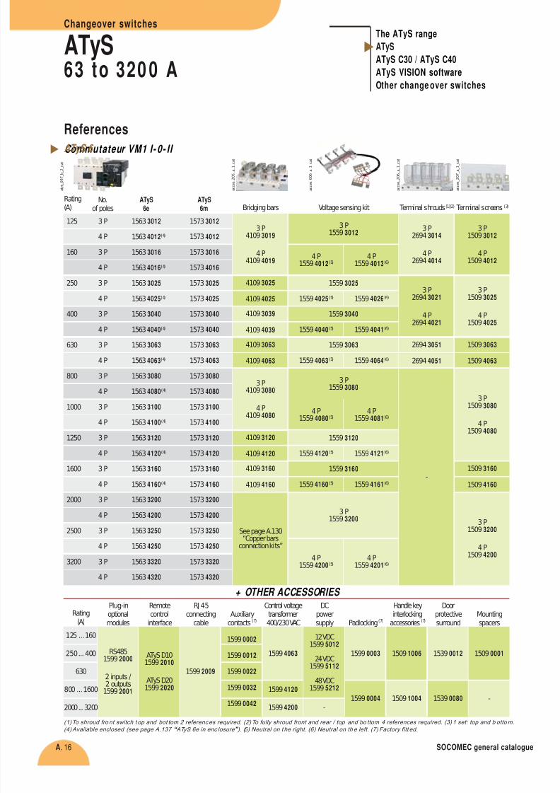
Bridging bars Terminal shrouds (1)(2) Terminal screens (3)
4109 3025
4109 4025
4109 3039
4109 4039
4109 3063
4109 4063
3 P2694 3021
4 P2694 4021
2694 3051
2694 4051
3 P1509 3025
4 P1509 4025
1509 3063
1509 4063
LATyS 3 ATyS 3
RS4851599 2000
2 inputs /2 outputs
1599 2001
12 VDC1599 5012
24 VDC1599 5112
48 VDC1599 5212 -
+ OTHER ACCESSORIES
7/29/2019 Socomec ATySM Catalog En
http://slidepdf.com/reader/full/socomec-atysm-catalog-en 16/42A. 16
References
LChangeover switches
ATyS63 to 320 0 A
The ATyS range
ATyS
ATyS C30 / ATyS C40
ATyS VISION software
Other change over switches
SOCOMEC general catalogue
800 3 P
4 P
1000 3 P
4 P
1563 3080
1563 4080(4)
1563 3100
1563 4100(4)
1250 3 P
4 P
1600 3 P
4 P
1563 3120
1563 4120(4)
1563 3160
1563 4160(4)
1573 3080
1573 4080
1573 3100
1573 4100
1573 3120
1573 4120
1573 3160
1573 4160
2000 3 P
4 P
1563 3200
1563 4200
1573 3200
1573 4200
2500 3 P
4 P
1563 3250
1563 4250
1573 3250
1573 4250
3200 3 P
4 P
1563 3320
1563 4320
1573 3320
1573 4320
4109 3120
4109 4120
4 P1559 4080 (5)
4 P1559 4081 (6)
4109 3160
4109 4160
1559 4120 (5) 1559 4121 (6)
1559 4160 (5) 1559 4161 (6)
1509 3160
1509 4160
3 P
1509 3080
4 P1509 4080
Rating(A)
125 ...160
250 ... 400
630
800 ...1600
2000 ... 3200
Plug-inoptionalmodules
Remotecontrol
interface
RJ 45connecting
cable
1599 0002
1599 0012
1599 0022
1599 0032
1599 0042
Auxiliarycontacts (7)
1599 4120
1599 4200 -
Control voltagetransformer400/230 VAC Padlocking (7)
Handle keyinterlocking
accessories (7)
Doorprotectivesurround
Mountingspacers
4 P1559 4200 (5)
4 P1559 4201 (6)
(1) To shroud fro nt switch t op and bot tom 2 referenc es required. (2) To fully shroud front and rear / top and bo ttom 4 references required. (3) 1 set: top and b ottom.
(4) Available enclosed (see page A.137 “ATyS 6e in enc losure”). (5) Neutral on t he right. (6) Neutral on th e left. (7) Factory fitt ed.
3 P4109 3080
4 P4109 4080
DCpowersupply
3 P1509 3200
4 P1509 4200
1509 00011539 00121509 10061599 00031599 4063
Rating(A)
No.of poles
125
160
250
3 P
4 P
3 P
4 P
3 P
4 P
400 3 P
4 P
630 3 P
4 P
1563 3012
1563 4012(4)
1563 3016
1563 4016
(4)
1563 3025
1563 4025(4)
1563 3040
1563 4040(4)
1563 3063
1563 4063(4)
ATyS6e
a t y s
_ 0 9 7
_ b
_ 2
_ c a
t
1573 3012
1573 4012
1573 3016
1573 4016
1573 3025
1573 4025
1573 3040
1573 4040
1573 3063
1573 4063
ATyS6m
4 P1559 4012 (5)
4 P1559 4013 (6)
Bridging bars Voltage sensing kit
4109 3025
4109 4025
4109 3039
4109 4039
4109 3063
4109 4063
1559 4025 (5) 1559 4026 (6)
LCommutateur VM1 I- 0- II ATyS 6
1559 4040 (5) 1559 4041 (6)
1559 4063 (5) 1559 4064 (6)
3 P2694 3014
4 P2694 4014
Terminal shrouds(1)(2)
3 P2694 3021
4 P2694 4021
2694 3051
2694 4051
3 P1509 3012
4 P1509 4012
Terminal screens (3)
3 P1509 3025
4 P1509 4025
1509 3063
1509 4063
3 P1559 3012
1559 3025
1559 3040
1559 3063
3 P4109 3019
4 P4109 4019
a c c e s
_ 2 0 5
_ a
_ 1
_ c a
t
a c c e s
_ 6 0 6
_ a
_ 1
_ c a
t
a c c e s
_ 2 0 6
_ a
_ 1
_ c a
t
a c c e s
_ 2 0 7
_ a
_ 1
_ c a
t
3 P1559 3200
1559 3160
1559 3120
3 P1559 3080
See page A.130
“Copper barsconnection kits”
-
12 VDC1599 5012
24 VDC1599 5112
48 VDC1599 5212
1599 0004 1509 1004 1539 0080 -
1599 2009
ATyS D101599 2010
ATyS D201599 2020
RS4851599 2000
2 inputs /2 outputs
1599 2001
+ OTHER ACCESSORIES

7/29/2019 Socomec ATySM Catalog En
http://slidepdf.com/reader/full/socomec-atysm-catalog-en 17/42A. 17
ATyS M - Accessories
Changeover switches
ATyS
SOCOM EC general ca talogue
Bridging bars
a t y s m
_ 0 2 5
_ a
_ 1
_ c a
t
References
Rating (A) No.of poles Reference
63 … 125
160
4
4
1309 4006
1309 4016
UseTo provide co mmon point on
either inco ming or outg oing
terminals.
Voltage sensing and pow er supply tap
ReferenceUseAllow s up to 2 x <= 1,5 mm2
voltage sensing or power cablesco nnec tion. To be mounte d in
any terminal cage when bridging
ba r not used
Rating (A) Reference
63 … 160
No.of parts
Pair 1399 4006 (1)
a t y s m
_ 0 2 6
_ a
_ 1
_ c a
t
Rating (A) Reference
63 … 160 2294 4016 (1)
Terminal shrouds
a t y s m
_ 0 2 7
_ a
_ 1
_ c a
t
Reference
No.of parts Position
Pair Top and bottom
UseP rotection ag ainst direct
conta ct w ith the connection
terminals or parts.
AdvantagesPerforations enabling remote
thermographic inspection
without dismantling.
Auxiliary contacts
a t y s m
_ 0 2 8
_ a
_ 1
_ c a
t
ReferenceUseUp to 2 auxiliary contacts
accessory per product.
Each a ccess ory integrates 3
NOC auxiliary co ntacts , one per
position I, 0, II.
Cha rac teristics : 250 VAC /5 A
maximum.
Rating (A) Reference
63 … 160 1309 0001
Reference
1359 0000
Sealable cover
Reference
Rating (A)
63 … 160
Use
Controls s ettings cover to a void
ATyS M 6s parameters ac cess
thanks to a sealable facility.
a t y s m
_ 0 4 3
_ a
(1) 2 parts pe r reference.
(1) To shroud front sw itch top and bot tom 2 references required.
7/29/2019 Socomec ATySM Catalog En
http://slidepdf.com/reader/full/socomec-atysm-catalog-en 18/42A. 18
LChangeover switches
ATyS63 to 320 0 A
The ATyS range
ATyS
ATyS C30 / ATyS C40
ATyS VISION software
Other change over switches
SOCOMEC general catalogue
ATyS - AccessoriesBridging bars
a c c e s
_ 2 0 5
_ a
_ 1
_ c a
t
a c c e s
_ 0 4 1
_ a
_ 1
_ c a
t
References
Rating (A) No. of poles Section (mm) Reference
125 … 160 3 20 x 2,5 4109 3019
125 … 160 4 20 x 2,5 4109 4019
250 3 25 x 2,5 4109 3025
250 4 25 x 2,5 4109 4025
400 3 32 x 5 4109 3039
400 4 32 x 5 4109 4039
630 3 50 x 5 4109 3063
630 4 50 x 5 4109 4063
800…
1000 3 50 x 6 4109 3080800… 1000 4 50 x 6 4109 4080
1250 3 60 x 8 4109 3120
1250 4 60 x 8 4109 4120
1600… 1800 3 90 x 10 4109 3160
1600… 1800 4 90 x 10 4109 4160
UseTo provide co mmon point on
either inco ming or o utgoing
terminals.
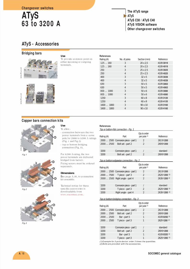
Copper bars connection k its
Fig.1
2
1
a c c e s
_ 2 2 6
_ a
_ 1
_ x_ c a
t
Fig.2
4
1
3
a c c e s
_ 2 2 8
_ a
_ 1
_ x_ c a
t
Fig.3
5
1
3
2
a c c e s
_ 2 3 0
_ a
_ 1
_ x_ c a
t
References
Top or bottom flat connection - Fig. 1
Rating (A) Reference
2000 … 2500
3200
3200
26991200
standard
26991200
Part
Bolt set - part 2
Bolt set - part 2
Qty to order
per pole(1)
2
/
2
Use
To a llow :
- connection betw een the two
powe r terminals from a sa me
pole for 2000 to 3200 A ratings(Fig. 1 and Fig 2)
- top or bottom bridging
connection (Fig. 3).
For 3200 A rating, the two
pow er terminals are d elivered
bridged from factory.
Fixing screws must be ordered
separately.
Dimensions
See pa ge A.35, to co nnection
kit assembly.
Tec hnica l not ice for thes e
spec ific a cce ss ories is
downloadable from
www.socomec.com.
2000 … 2500 261912002
Top or bottom edgewise connection - Fig. 2
Rating (A) Reference
2000 … 2500
3200
3200
2639 1200 (2)
standard
2639 1200 (2)
Part
Right angle - part 4
Right angle - part 4
Qty to orderper pole(1)
2
/
2
3200 2629 1200 (2) T piece - part 3 2
2000 … 2500 261912002
2000 … 2500 T piece - part 3 2 2629 1200 (2)
Top or bottom bridging connection - Fig. 3
Rating (A) Reference
2000 … 2500
3200
3200
4109 0250 (2)
standard
4109 0320 (2)
Part
Bar - part 5
Bar - part 5
Qty to orderper pole (1)
1
/
1
3200 26991200Bolt set - part 2 2
3200 2629 1200 (2) T piece - part 3 1
2000 … 2500 261912002
2000 … 2500 Bolt set - part 2 2
2000 … 2500 26291200 (2) T piece - part 3 1
(1) Example for 3-po le device: order 3 times t he quantities.
(2) Bolts are provided with t he accessories.
26991200
Connexion piece - part 1
Connexion piece - part 1
Connexion piece - part 1
Connexion piece - part 1
Connexion piece - part 1
Connexion piece - part 1
7/29/2019 Socomec ATySM Catalog En
http://slidepdf.com/reader/full/socomec-atysm-catalog-en 19/42A. 19
Changeover switches
ATyS
SOCOM EC general ca talogue
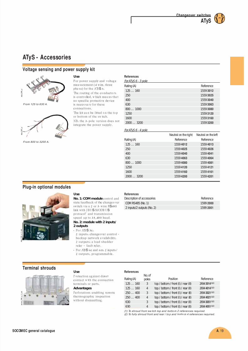
ATyS - AccessoriesVoltage sensing and power supply kit
a t y s
_ 6 0 6
_ a
a t y s
_ 6 0 3
_ a
References
For ATyS 6 - 3 pole
Rating (A) Reference
125 … 160 1559 3012
250 1559 3025
400 1559 3040
630 1559 3063
800 … 1000 1559 3080
1250 1559 3120
1600 1559 3160
2000 … 3200 1559 3200
For ATyS 6 - 4 pole
Rating (A)
Neutral on the right Neutral on the left
Reference Reference
125 … 160 1559 4012 1559 4013
1250 1559 4120 1559 4121
1600 1559 4160 1559 4161
250 1559 4025 1559 4026
400 1559 4040 1559 4041
630 1559 4063 1559 4064
800 … 1000 1559 4080 1559 4081
2000 … 3200 1559 4200 1559 4201
Use
For power supply and voltag e
mea surement (4 wire, three
pha se) for th e ATyS 6.
The routing of the co nducto rs
is controlled, w hich mea ns tha t
no specific protective device
is neces sa ry for these
connections.
The kit ca n be fitted o n the to p
or bottom of the sw itch.
NB: the 3-pole version does not
integrate the power supply.
From 125 to 630 A.
From 800 to 3200 A.
Plug-in optional modules
a t y s
_ 0 1 6
_ a
_ 1
_ c a
t
References
Description of accessories Reference
COM RS485 (No. 1) 1599 2000
2 inputs/2 outputs (No. 2) 1599 2001
Use
No. 1: COM module control and
state feedba ck of the changeo ver
switch via a 2 or 3-wire RS485
link with J BUS/MODB USprotocol® and transmission
speed up to 38,400 baud.
No. 2: module with 2 inputs/2 outputs
• For ATyS 3e:
2 inputs: changeover control +
ba ckup network a vailab ility;2 outputs: a load shedder
relay + fault relay.
• For ATyS 6e and 6m: 2 inputs/
2 outputs, programmab le.
Terminal shrouds
a c c e s
_ 2 0
6_
a_
1_
c a
t
References
Rating (A)No.of poles Position Reference
125 … 160 3 top / bottom / front (I) / rear (II) 26943014(1)(2)
125 … 160 4 top / bottom / front (I) / rear (II) 26944014(1)(2)
250 … 400 3 top / bottom / front (I) / rear (II) 26943021(1)(2)
250 … 400 4 top / bottom / front (I) / rear (II)26944021(1)(2)
630 3 top / bottom / front (I) / rear (II) 26943051(1)(2)
630 4 top / bottom / front (I) / rear (II) 26944051(1)(2)
(1) To shroud front sw itch top and botto m 2 references required.
(2) To fully shroud front and rear / to p and botto m 4 references required.
Use
P rotection ag ainst direct
conta ct w ith the connection
terminals or parts.
Advantages
Perforations enabling remote
thermographic inspection
without dismantling.
7/29/2019 Socomec ATySM Catalog En
http://slidepdf.com/reader/full/socomec-atysm-catalog-en 20/42A. 20
LChangeover switches
ATyS63 to 320 0 A
The ATyS range
ATyS
ATyS C30 / ATyS C40
ATyS VISION software
Other change over switches
SOCOMEC general catalogue
ATyS - Accessories
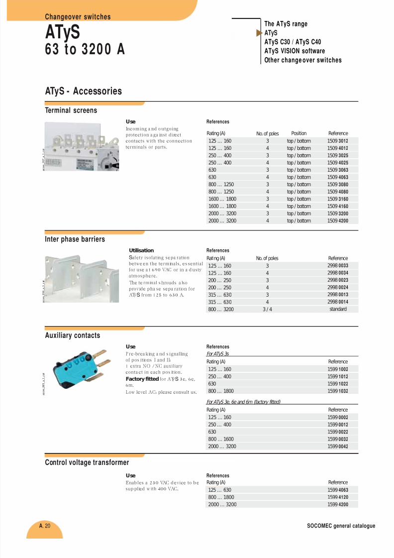
Control voltage transformer
ReferencesRating (A) Reference
125 … 630 1599 4063
800 … 1800
2000 … 3200
1599 4120
1599 4200
UseEnab les a 230 VAC d evice to b e
sup plied w ith 400 VAC.
Auxiliary contacts
a c c e s
_ 0 6 5
_ a_
1_
c a
t
References
For ATyS 3s
Rating (A) Reference
125 … 160 1599 1002
250 … 400 1599 1012
630 1599 1022
800 … 1800 1599 1032
For ATyS 3e, 6 e and 6 m (factory fitted)
Rating (A) Reference
125 … 160 1599 0002
250 … 400 1599 0012
630 1599 0022
800 … 1600 1599 0032
2000 … 3200 1599 0042
Use
P re-brea king a nd s ignalling
of pos itions I and II:
1 extra NO /NC auxiliary
conta ct in each pos ition.
Factory fitted for ATyS 3e, 6e,6m.
Low level AC: please consult us.
Terminal screens
a c c e s
_ 2 0 7
_ a
_ 1
_ c a
t
References
Rating (A) No.of poles Position Reference
125 … 160 3 top / bottom 1509 3012
125 … 160 4 top / bottom 1509 4012
250 … 400 3 top / bottom 1509 3025
250 … 400 4 top / bottom 1509 4025
630 3 top / bottom 1509 3063
630 4 top / bottom 1509 4063
800 … 1250 3 top / bottom 1509 3080
800 … 1250 4 top / bottom 1509 4080
1600 … 1800 3 top / bottom 1509 3160
1600 … 1800 4 top / bottom 1509 4160
2000 … 3200 3 top / bottom 1509 3200
2000 … 3200 4 top / bottom 1509 4200
Use
Incoming a nd o utgoing
protection a ga inst direct
contacts with the connection
terminals or parts.
Inter phase barriers
a c c e s
_ 0 3 6
_ a
_ 1_
c a
t
References
Rating (A) No.of poles Reference
125 … 160 3 2998 0033
125 … 160 4 2998 0034
200 … 250 3 2998 0023
200 … 250 4 2998 0024
315 … 630 3 2998 0013
315 … 630 4 2998 0014
800 … 3200 3 / 4 standard
Utilisation
Safety isolating sepa ration
betwe en the terminals, es sential
for use a t 690 VAC or in a d usty
atmosphere.
The te rminal s hrouds a lsoprovide pha se sepa ration for
ATyS from 125 to 630 A.
7/29/2019 Socomec ATySM Catalog En
http://slidepdf.com/reader/full/socomec-atysm-catalog-en 21/42A. 21
Changeover switches
ATyS
SOCOM EC general ca talogue
ATyS - Accessories
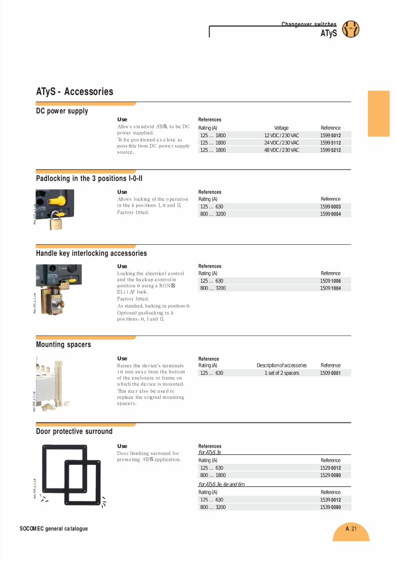
Padlocking in the 3 positions I-0-II
A t y s
_ 1 2 5
_ a
_ 1
_ c a
t
ReferencesRating (A) Reference
125 … 630 1599 0003
800 … 3200 1599 0004
UseAllows locking of the o peration
in the 3 pos itions I, 0 and II.
Factory fitted.
DC pow er supplyReferences
Rating (A) Voltage Reference
125 … 1800 1599 5012
125 … 1800 1599 5112
125 … 1800 1599 5212
Use
Allow s s ta nd a rd ATyS, to be DC
power supplied.
To b e pos itioned a s c lose as
poss ible from DC powe r supply
source.
12 VDC / 230 VAC
24 VDC / 230 VAC
48 VDC / 230 VAC
Mounting spacers
a t y s
_ 0 0 9
_ a
_ 1
_ c a
t
Reference
Rating (A) Description of accessories Reference
125 … 630 1 set of 2 spacers 1509 0001
Use
Raises the device’s terminals
10 mm awa y from the bottom
of the enclosure or frame on
which the device is mounted.
This ma y also be use d to
repla ce the o riginal mounting
spacers.
Handle key interlocking accessories
A t y s
_ 1 0 1
_ a
_ 1
_ c a
t
References
Rating (A) Reference
125 … 630 1509 1006
800 … 3200 1509 1004
Use
Locking the electrica l control
and the ba ckup control in
position 0 using a RONISEL11AP lock.
Factory fitted.
As standard, locking in position 0.
Optional pa dlocking in 3
pos itions : 0, I and II.
Door protective surround
a t y s
_ 5 9 5
_ a
_ 1
_ c a t
ReferencesFor ATyS 3s
Rating (A) Reference
125 … 630 1529 0012
800 … 1800 1529 0080For ATyS 3e, 6 e and 6 m
Rating (A) Reference
125 … 630 1539 0012
800 … 3200 1539 0080
Use
Doo r finishing surround for
pro te cting ATyS application.
7/29/2019 Socomec ATySM Catalog En
http://slidepdf.com/reader/full/socomec-atysm-catalog-en 22/42A. 22
LChangeover switches
ATyS63 to 320 0 A
The ATyS range
ATyS
ATyS C30 / ATyS C40
ATyS VISION software
Other change over switches
SOCOMEC general catalogue
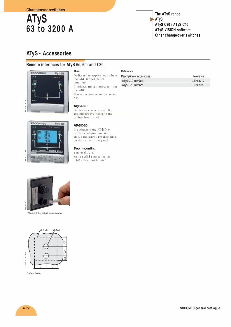
ATyS - AccessoriesRemote interfaces for ATyS 6e, 6m and C30
a t y s
_ 5 6 4
_ c
_ 1
_ c a
t
a t y s
_ 5 6 5
_ c
_ 1
_ c a
t
Reference
Description of accessories Reference
ATyS D10 interface
ATyS D20 interface
1599 2010
1599 2020
Use
Dedica ted to applica tions w here
the ATyS is b ack panel
mounted.
Interfaces are self powered from
the ATyS.
Maximum co nnection distance:
3 m .
ATyS D10
To disp lay s ource a va ila bilityand c hangeover state on the
cabinet front panel.
ATyS D20
In add ition to the ATyS D10
display configuration, and
sta tus and a llow s programming
on the cabinet front panel.
Door mounting
2 holes Ø 22.5.
Ma s te r ATyS connection via
RJ45 cab le, not isolated.
Drilled holes.
a t y s
_ 5 9 7
_ a
Ø 22.5
4 0
3 6
2 0
= =
96 x 96
a t y s
_ 1 6 1
_ a
_ 1
_ x_ c a
t
RJ45 link for ATyS con nection.
7/29/2019 Socomec ATySM Catalog En
http://slidepdf.com/reader/full/socomec-atysm-catalog-en 23/42A. 23
Changeover switches
ATyS
SOCOM EC general ca talogue
ATyS - Accessories
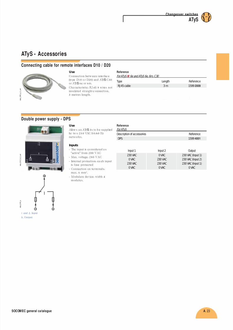
Double power supply - DPS
Reference
Description of accessories Reference
DPS 1599 4001
Input 1 Output
230 VAC 230 VAC (Input 1)
Input 2
0 VAC
0 VAC 230 VAC (Input 2)230 VAC
230 VAC 230 VAC (Input 1)230 VAC
0 VAC 0 VAC0 VAC
Use
Allow s a n ATyS 3s to b e supplied
by tw o 230 VAC 50/60 Hz
networks.
Inputs
- The input is co nsidered a s
“active” from 200 VAC
- Max. voltage: 280 VAC
- Internal protection: ea ch input
is fuse protected
- Connection on terminals:max. 6 mm2.
- Modulare device: width 4
modules.
a t y s
_ 6 1 2
_ b
_ 2
_ c a
t
3
21 a
t y s
_ 6 1 6
_ a
1 and 2. Input
3. Output.
For ATyS
Connecting cable for remote interfaces D10 / D20
Use
Connection betw een interfac e
(type D10 o r D20) an d ATyS C30
or ATyS 6e or 6m.
Cha racteristic: RJ 45 8 wires not
insulated straight c onnection,
3 metres length.
a t y s
_ 2 0 9
_ a
_ 1
_ c a
t
Type Reference
RJ45 cable
Length
3 m 1599 2009
Reference
For ATyS M 6 e and ATyS 6 e, 6 m, C30
7/29/2019 Socomec ATySM Catalog En
http://slidepdf.com/reader/full/socomec-atysm-catalog-en 24/42A. 24
LChangeover switches
ATyS63 to 320 0 A
The ATyS range
ATyS
ATyS C30 / ATyS C40
ATyS VISION software
Other change over switches
SOCOMEC general catalogue
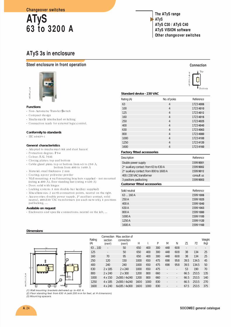
ATyS 3s in enclosureSteel enclosure in front operation
Functions
• Non-Automa tic Trans fer Switch• Compact design
• Mecha nica lly interloc ked sw itching
• Connection ready for external logic c ontrol.
Conformity to standards
• IEC 60439-1
General characteristics• Ada pted to mecha nica l risk and d ust haza rd
• Protection degree: IP 54
• Co lour: RAL 7035
• Closing plates: top and bottom
• Ca ble gland plate: to p or bottom from 63 to 250 A,
bo ttom from 400 to 1600 A• Material: steel thickness 2 mm
• Coa ting: epoxy polyester powder
• Wa ll mounting: 4 wa ll mounting brac kets s upplied - not mo unted(ra ting ≤ 400 A), floor standing feet (rating > 630 A)
• Door: solid w ith hinges
• Locking s yste m: 3 mm doub le-ba r key(key supplied)
• Misc ellane ous: 2 ea rth co nnection points, neutral on the right.
• Acc ess ories: d ouble power supply, 2nd auxiliary contact, solidneutra l, 400/230 VAC tra ns formers (on e a ch ne tw ork), 3 pos itionspad locking, ...
Available on request
• Enclosures a nd spec ific c onnections: neutral on the left, ...
Rating (A) Reference
Dimensions
c o
f f_ 3 0 5
_ a
_ 1
_ c a
t
Standard device - 230 VAC
LM
H N
2 2 3
12,5
P
10,5Z1
Z2
3
1
2 a t y s
_ 6 1 9
_ c_
1_
f r_ c a
t
(1) Wall mounting brackets delivered up to 400 A.
(2) Floor standing feet from 630 A (add 200 m m for feet, at H d imension).
(3) Mount ing spacers.
Rating(A)
Max. section of connection
(mm2)
Weight(kg)
50 -
160 95 25
250 150 45
400 240 50
630 2 x 240 70
800 2 x 300 135
1000 2x300 / 4x240 1401250 2x300 / 4x240 270
1600 6x185 / 4x300 375
Z2
-
134
134.5
134.5
190
253.5
253.5253.5
253.5
Z1
-
38
39.5
39.5
53
66.5
66.5
66.5
67.5
N
608
608
958
958
-
-
--
-
M
448
448
698
698
-
-
--
-
P
300
300
475
475
475
660
660
830
830
L
400
400
650
650
650
800
8001000
1000
H
650
650
1000
1000
1000
1200
12001600
1600
Connectionsection(mm2)
-
70
120
240
2 x 185
2 x 240
4 x 1504 x 185
4 x 240
125 50 2513438608448300400650-
63 1723 4006
160 1723 4016
250 1723 4025
400 1723 4040
630 1723 4063
800 1723 4080
1000 1723 4100
1250 1723 4120
1600 1723 4160
No.of poles
4
4
4
4
4
4
4
4
4
100 1723 40104
125 1723 40124
Solid neutral Reference
Customer fitted accessories
63 ...160 A 1599 1006
250 A 1599 1025
400 A 1599 1040
630 A 1599 1063
800 A 1599 1080
1000 A 1599 1100
1250 A 1599 1120
1600 A 1599 1160
Description Reference
Factory fitted accessories
Double power supply 1599 9001
2nd auxiliary contact: from63 to 630 A 1599 90022nd auxiliary contact: from 800 to 1600 A 1599 9012
400 / 230 VAC transformer
3 positions padlocking 1599 9003
Top
Bottom
Connection
c o
f f_ 2 3 0
_ b
_ 1
_ g
b_
c a
t
consult us
63 ...100
7/29/2019 Socomec ATySM Catalog En
http://slidepdf.com/reader/full/socomec-atysm-catalog-en 25/42A. 25
Changeover switches
ATyS
SOCOM EC general ca talogue
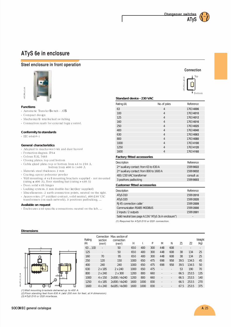
ATyS 6e in enclosureSteel enclosure in front operation
Functions
• Automa tic Trans fer Sw itch - ATS• Compact design
• Mecha nica lly interloc ked sw itching
• Connection ready for external logic c ontrol.
Conformity to standards
• IEC 60439-1
General characteristics
• Ada pted to mecha nica l risk and dust ha zard
• Protection degree: IP54
• Co lour: RAL 7035
• Closing plates: top a nd bottom
• Ca ble gland plate: to p or bottom from 63 to 250 A,
bottom from 400 to 1600 A• Material: steel thickness 2 mm
• Coa ting: epoxy polyester powder
• Wall mounting: 4 wa ll mounting brac kets s upplied - not mo unted(rating ≤ 400 A), floor standing feet (rating > 630 A)
• Door: solid w ith hinges
• Locking s yste m: 3 mm double-ba r key(key supplied)
• Misc ella neous : 2 earth connec tion points, neutral on the right.
• Access ories: 2nd a uxiliary c ont a ct , s olid neutra l, 400/230 VACtransformers (on each network), 3 positions padlocking, ...
Available on request
• Enclos ures a nd spec ific c onnections: neutral on the left, ...
c o
f f_ 3 0 6
_ a
_ 1
_ c a
t
Reference
Customer fitted accessories
1599 2010
1599 2020
1599 2009
1599 2000
1599 2001
-
Description
ATyS D10
ATyS D20
RJ45 connection cable(1)
Communication RS485 MODBUS
2 inputs / 2 outputs
Solid neutral (see page A.136 “ATyS 3s in enclosure”)
Rating (A) Reference
Dimensions
Standard device - 230 VAC
LM
H N
12,5
P
2 8 0
Z1
Z21
2
3
a t y s
_ 6 2 1
_ b_ 1
_ f r_
c a
t
(1) Wall mounting b rackets delivered up to 400 A.
(2) Floor standing feet from 630 A (add 200 mm for feet, at H dimension).
(3) ATyS D10 o r D20 int erfaces.
(1) Required for ATyS D10 or D20 connection.
Rating(A)
Max.section of connection
(mm2)
Weight(kg)
50 -
160 95 25
250 150 45
400 240 50
630 2 x 240 70
800 2 x 300 135
1000 2x300 / 4x240 1401250 2x300 / 4x240 270
1600 6x185 / 4x300 375
Z2
-
134
134.5
134.5
190
253.5
253.5253.5
253.5
Z1
-
38
39.5
39.5
53
66.5
66.5
66.5
67.5
N
608
608
958
958
-
-
--
-
M
448
448
698
698
-
-
--
-
P
300
300
475
475
475
660
660
830
830
L
400
400
650
650
650
800
8001000
1000
H
650
650
1000
1000
1000
1200
12001600
1600
Connectionsection(mm2)
-
70
120
240
2 x 185
2 x 240
4 x 1504 x 185
4 x 240
125 50 2513438608448300400650-
63 1763 4006
160 1763 4016
250 1763 4025
400 1763 4040
630 1763 4063
800 1763 4080
1000 1763 4100
1250 1763 4120
1600 1763 4160
No.of poles
4
4
4
4
4
4
4
4
4
100 1763 40104
125 1763 40124
Description Reference
Factory fitted accessories
2nd auxiliary contact: from63 to 630 A 1599 90222nd auxiliary contact: from 800 to 1600 A 1599 9032
400 / 230 VAC transformer
3 positions padlocking 1599 9003
Top
Bottom
Connection
c o
f f_ 2 3 0
_ b
_ 1
_ g
b_
c a
t
consult us
63 ...100
7/29/2019 Socomec ATySM Catalog En
http://slidepdf.com/reader/full/socomec-atysm-catalog-en 26/42A. 26
LChangeover switches
ATyS63 to 320 0 A
The ATyS range
ATyS
ATyS C30 / ATyS C40
ATyS VISION software
Other change over switches
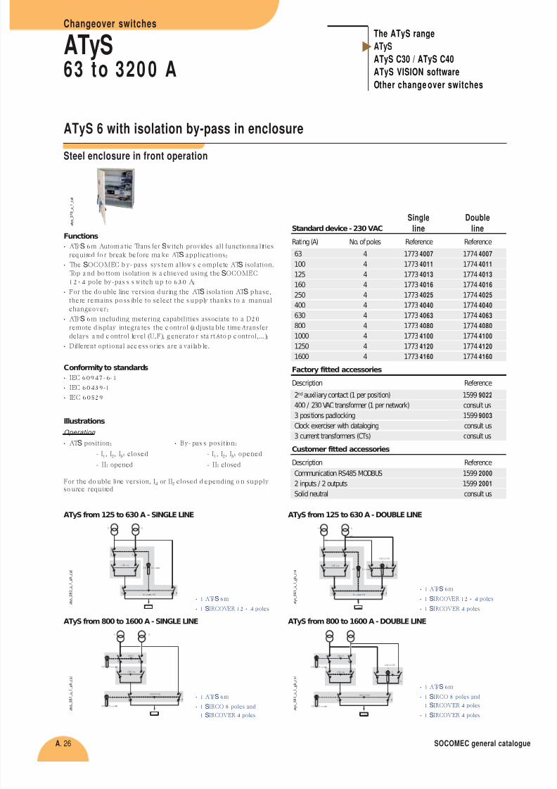
ATyS 6 with isolation by-pass in enclosure
SOCOMEC general catalogue
Functions
• ATyS 6m Autom a tic Trans fer Switch provides all functionna lities
req uired fo r break be fore ma ke ATS applications;
• The SOCOMEC b y-pass sys tem allow s c omplete ATS isolation.
Top a nd bo ttom isolation is a chieved using the SOCOMEC
12+ 4 pole by-pas s s witch up to 630 A;
• For the do uble line version d uring the ATS isola tion ATS phase,
there remains po ss ible to select the s upply thanks to a manual
changeover;
• ATyS 6m including metering capabilities associate to a D20
remote d isplay integra tes the c ontrol (a djusta ble time/transfer
delays a nd c ontrol level (U,F), g enerato r sta rt/sto p c ontrol,...);
• Different optional acc ess ories are a vailab le.
Conformity to standards
• IEC 60947-6-1
• IEC 60439-1
• IEC 60529
Illustrations
Operation
• ATS position:
- I1, I2, I3: closed
- II: opened
• By-pas s position:
- I1, I2, I3: opened
- II: closed
For the do uble line version, I4 or II2 closed d epending o n supplyso urce required
Rating (A) Reference
a t y s
_ 0 7 9
_ a
_ 1
_ c a
t
Standard device - 230 VAC
63 1774 4007
125 1774 4013
160 1774 4016
250 1774 4025
400 1774 4040
630 1774 4063
800 1774 4080
1250 1774 4120
1600 1774 4160
No.of poles
4
4
4
4
4
4
4
4
4
100 1774 4011
Reference
1773 4007
1773 4013
1773 4016
1773 4025
1773 4040
1773 4063
1773 4080
1773 4120
1773 4160
1000 1774 41004 1773 4100
1773 40114
Description Reference
Customer fitted accessories
Communication RS485 MODBUS 1599 2000
2 inputs / 2 outputs 1599 2001
Solid neutral consult us
Description Reference
Factory fitted accessories
2nd auxiliary contact (1 per position) 1599 9022
400 / 230 VAC transformer (1 per network) consult us3 positions padlocking 1599 9003
Clock exerciser with dataloging
3 current transformers (CTs) consult us
consult us
Steel enclosure in front operation
Singleline
Doubleline
a t y s
_ 0 8 0
_ a
_ 1
_ g
b_
c a
t
T1 T2
III3
I2I1
ATyS 6m
Load
By-pass ATS
ATS By-pass
ATyS from 125 to 630 A - SINGLE LINE
a t y s
_ 0 8 1
_ a
_ 1
_ g
b_
c a
t
T1 T2
S2
I4
III3
I2I1
S1
ATyS 6m
Load
By-passATS
SIRCOVER
ATS B y-pass
III
0
II2
ATyS from 125 to 630 A - DOUBLE LINE
a t y s
_ 0 8 2
_ a
_ 1
_ g
b_
c a
t
T1 T2
III3
I2I1
ATyS 6m
Load
SIRCOVER
ATS B y-p ass
SIRCO
ATS B y-p ass
ATyS from 800 to 1600 A - SINGLE LINE
a t y s
_ 0 8 3
_ a
_ 1
_ g
b_
c a
t
T1 T2
I4
III3
I2I1
ATyS 6m
Load
SIRCOVER
SIRCOVERATS B y-p ass
III
0
II2
SIRCO
ATS B y-p ass
ATyS from 800 to 1600 A - DOUBLE LINE
• 1 ATyS 6m
• 1 SIRCOVER 12 + 4 poles
• 1 ATyS 6m
• 1 SIRCOVER 12 + 4 poles
• 1 SIRCOVER 4 poles
• 1 ATyS 6m
• 1 SIRCO 8 poles and
1 SIRCOVER 4 poles
• 1 ATyS 6m
• 1 SIRCO 8 poles and
1 SIRCOVER 4 poles
• 1 SIRCOVER 4 poles
7/29/2019 Socomec ATySM Catalog En
http://slidepdf.com/reader/full/socomec-atysm-catalog-en 27/42A. 27
Changeover switches
ATyS
SOCOM EC general ca talogue
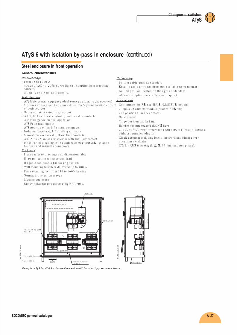
General characteristics
Product range
• From 63 to 1600 A
• 400/230 VAC + /- 20%, 50/60 Hz; s elf supp lied from inco mingsources
• 4 pole, 3 or 4 wires applica tions.
Main features
• ATS logic co ntrol sequence (dual source a utomatic cha ngeover)
• 3 phases vo ltag e and freq uency detection &phase rotation controlof both sources
• Generator sta rt /stop relay output
• ATS I, 0, II elec trica l control by volt free d ry conta cts
• ATS Emergency manual ope ration
• ATS Fault relay output
• ATS pos ition 0, I and II auxiliary conta cts
• Iso lation by-pas s 0, I, II a uxilia ry co ntac ts
• Manua l cha ngeo ver 0, I, II a uxilia ry co nta cts
• ATS Auto /Manual key selector with auxiliary contact
• 0 pos ition pa dlocking, with auxilia ry conta ct o ut ATS, isolationby-pass a nd manual cha ngeover.
Enclosure
• Pleas e refer to draw ings a nd dimension table
• IP 40 protection rating as s tanda rd
• Hinged d oor, double bar locking s ystem
• Wall mounting b rackets delivered up to 400 A
• Floo r sta nding feet from 630 to 1600 A rating• Termina ls p rotection sc reen
• Metallic enclosure
• Epoxy polyester pow der coa ting RAL 7035.
Cable entry
• Bottom cable entry as s tandard
• Specific cable entry requirements available upon request
• Neutral position located on the right a s s tanda rd
• Alternative options ava ila ble upon reques t.
Accessories
• Communica tion RS 485 JB US /MODBUS module
• 2 inputs /2 o utputs mo dule (refer to ATyS 6m)
• 2nd pos ition a uxiliary co ntacts• Solid neutral
• Three pos ition pad loc king
• Hand le key interlocking (RONIS key)
• 400 /230 VAC trans formers (on e ac h netw ork) for app lica tions
without neutral conduc tor
• Clock exerciser including loss of network and c hange over
operation da taloging
• CTs for ATyS mete ring (P, Q, S, P F total and per phas e).
ATyS 6 with isolation by-pass in enclosure (continued)Steel enclosure in front operation
a t y s
_ 0 8 4
_ a
_ 1
_ g
b_
c a
t
a t y s
_ 0 8 5
_ a
_ 1
_ g
b_
c a
t
SIRCOVER b y-passATS 12 + 4
Up to 400 A
From to 630 ALOAD Earth connection
Cu 15 x 3
SIRC OVER
ATyS 6m
optional control
1-2 2-2 1-2
By-passATS
Q3
Q1
Q2
N
133.1
2 0 7 . 6
Grand plate
Example: ATyS 6m 400 A - doub le line version with isolation by-p ass in enclosure.
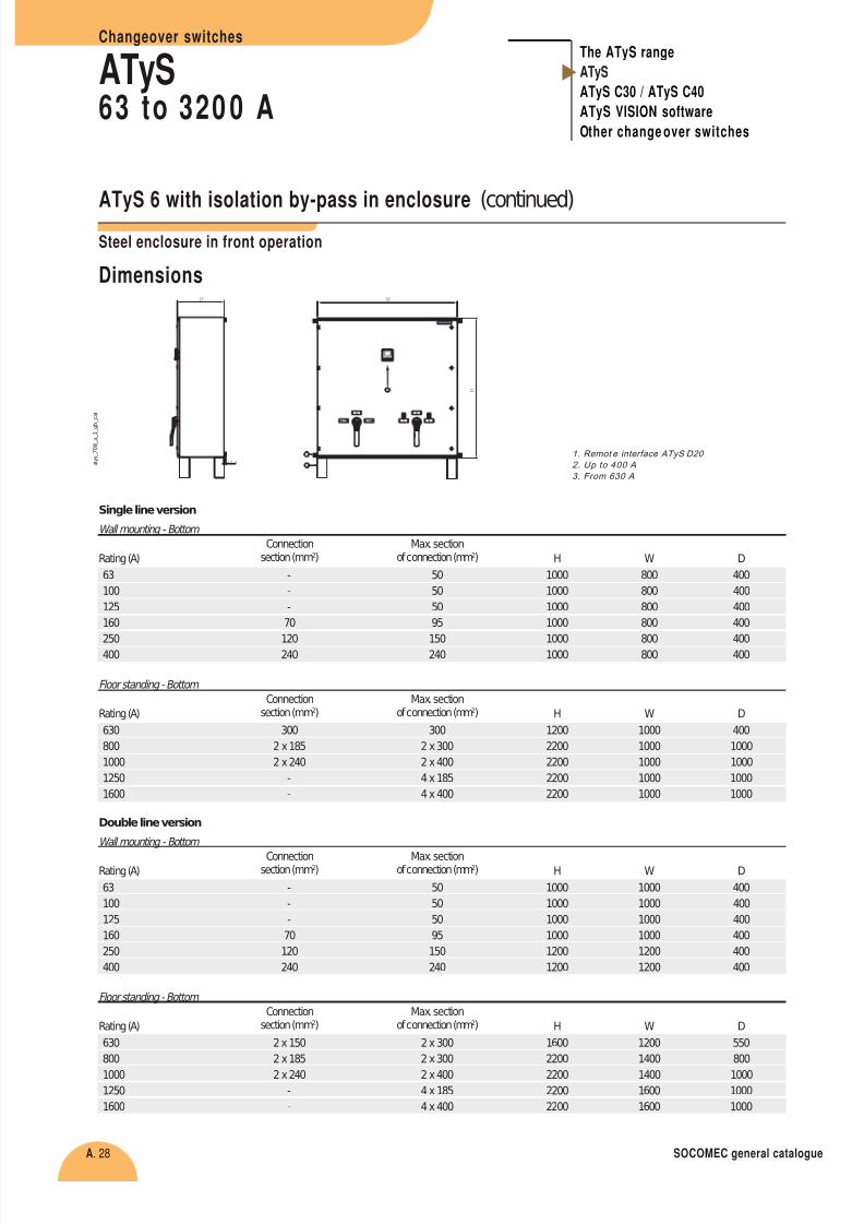
7/29/2019 Socomec ATySM Catalog En
http://slidepdf.com/reader/full/socomec-atysm-catalog-en 28/42A. 28
LChangeover switches
ATyS63 to 320 0 A
The ATyS range
ATyS
ATyS C30 / ATyS C40
ATyS VISION software
Other change over switches
ATyS 6 with isolation by-pass in enclosure (continued)
SOCOMEC general catalogue
Rating (A) H W
63 1000 1000
160 1000 1000
250 1200 1200
400 1200 1200
D
400
400
400
400
Connectionsection (mm2)
-
70
120
240
Max. sectionof connection (mm2)
50
95
150
240
Wall mounting - Bottom
1. Remot e interface ATyS D20
2. Up to 400 A
3. From 630 A
100 1000 1000 400- 50
125 1000 1000 400- 50
Rating (A) H W
630 1600 1200
1250 2200 1600
1600 2200 1600
D
550
1000
1000
Connectionsection (mm2)
2 x 150
-
-
Max. sectionof connection (mm2)
2 x 300
4 x 185
4 x 400
Floor standing - Bottom
800 2200 1400 8002 x 185 2 x 300
1000 2200 1400 10002 x 240 2 x 400
W
H
D
1
2
12.53
Dimensions
a t y s
_ 7 0 8
_ a
_ 1
_ g
b_ c
a t
Double line version
Rating (A) H W
63 1000 800
160 1000 800250 1000 800
400 1000 800
D
400
400400
400
Connectionsection (mm2)
-
70120
240
Max. sectionof connection (mm2)
50
95150
240
Wall mounting - Bottom
100 1000 800 400- 50
125 1000 800 400- 50
Rating (A) H W
630 1200 1000
1250 2200 1000
1600 2200 1000
D
400
1000
1000
Connectionsection (mm2)
300
-
-
Max. sectionof connection (mm2)
300
4 x 185
4 x 400
Floor standing - Bottom
800 2200 1000 10002 x 185 2 x 300
1000 2200 1000 10002 x 240 2 x 400
Single line version
Steel enclosure in front operation

7/29/2019 Socomec ATySM Catalog En
http://slidepdf.com/reader/full/socomec-atysm-catalog-en 29/42A. 29
Changeover switches
ATyS
SOCOM EC general ca talogue
Functional diagram
P riority source
Backup source
1: position 0 control
2: position I control
3: pos ition II control
4: position control inhibition inputs (0-I-II)
5: auxiliary contac t, closed when the s witch is in position I
6: auxiliary contac t, closed when the s witch is in position II
7: auxiliary contac t, closed when the s witch is in position 0
8: auxiliary contac t, closed when the s witch is on “ AUT” mo de
9: auxiliary conta ct, closed when the sw itch is pa dlocked
10: gen-set start command
11: auxiliary power supply (for optional modules control)
12: remote “ test on-load ”input
13: DTT inhibit input. Trans fer initiat ed a s s oon a s the input is close d w henDTT= max. va lue.
14: fault output
15: remote control interface
16: slots for optional mod ules
17: 3 c urrent tra ns forme rs (Cts ) for ATyS metering
18: by-pass po sition
19: ATS position
20: P riority so urce used
21: Ba ckup source used
101 - 102: supp ly 220 -20% /240 + 20%201 - 202: supp ly 220 -20% /240 + 20%2
1
2
1
2
1
7 3
2 1 0
2 0 9
2 0 8
2 0 7
2 0 6
2 0 5
2 0 4
2 0 3
2 0 2
2 0 1
7 4
P o w e r 2 3 0 V A C
2
P ow e r 2 3 0 VA C
13
5 6 7 8 9
1211
10
43
21
14
1
15
1314 243443 445354
1 0 1
1 0 2
1 0 3
1 0 4
1 0 5
1 0 6
3 1 3
3 1 4
3 1 5
3 1 6
3 1 7
6 3
6 4
R J
L 1
L 2
L 3
N L 1
L 2
L 3
N
16
1314 243443 445354
3 1 3
3 1 4
3 1 5
3 1 6
3 1 7
6 3
6 4
R J
7 3
2 1 0
2 0 9
2 0 8
2 0 7
7 4
12
Load
ATyS
6m
17
V ol t a g e s e n s i n g
V o l t a g e s e n s i n g
2
1
3
5
4
6
8
7
9
1 1
1 0
1 2
18
19
20
21
Manual changeover(only for the doub le line)
A
Isolationby-pass
B+ C SIRC OVER 12+ 4p (from 63A to 630A)
B SIRCOVER 8p (from 800A to 1600A)
C SIRCOVER 4p (from 800A to 1600A)
C C
A
B
A
B
a t y s
_ 0 8 6
_ a
_ 1
_ g b
_ c a
t
Environment
• Operating temperature: -10 to + 40 °C without de-rating
• Operating temperature: + 40 to + 65 °C w ith de-rating
• Maximum storag e is one year
• 80 % humidity non condensing at + 55 ° C
• 95 % humidity non condensing at + 40 °C
• Maximum operating altitude w ithout sw itch de-ra ting is 2000 mabove sea level.
The complete enclosure meets the following environmental requirements:
ATyS 6 with isolation by-pass in enclosure (continued)Steel enclosure in front operation
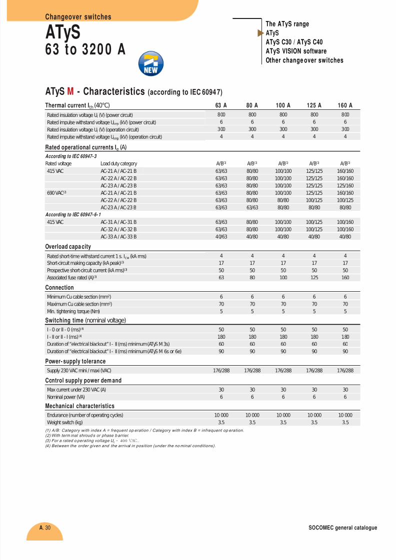
7/29/2019 Socomec ATySM Catalog En
http://slidepdf.com/reader/full/socomec-atysm-catalog-en 30/42A. 30
ATyS M - Characteristics (according to IEC 6094 7)80 A 100 A 125 A
Rated operational currents Ie (A)
Rated voltage
According to IEC 60947- 3
Load duty category A/B(1) A/B(1) A/B(1)
415 VAC AC-21 A / AC-21 B
(1) A/B: Category with index A = frequent op eration / Category with index B = infrequent op eration.
(2) With term inal shroud s or phase barrier.
(3) For a rated o perating voltage U e = 400 VAC .(4) Between the order given and the arrival in position (under the nominal conditions).
Thermal current Ith(40°C)
Rated insulation voltage Ui (V) (power circuit)
Rated impulse withstand voltage Uimp (kV) (power circuit)
Overload capa city
Rated short-time withstand current 1 s. Icw (kA rms)
Short-circuit making capacity (kA peak)(3)
ConnectionMinimum Cu cable section (mm2)
Maximum Cu cable section (mm2)
Min. tightening torque (Nm)
Switching time (nominal voltage)
I - 0 or II - 0 (ms)(4)
I - II or II - I (ms)(4)
Power- supply tolerance
Supply 230 VAC mini / maxi (VAC)
Control supply power dem andMax current under 230 VAC (A)
Mechanical characteristics
Endurance (number of operating cycles)
Weight switch (kg)
80/80 100/100 125/125
A/B(1)
160/160
AC-22 A / AC-22 B 80/80 100/100 125/125 160/160
AC-23 A / AC-23 B 80/80 100/100 125/125 125/160
A/B(1)
63/63
63/63
63/63
800 800 800
6 6 6
63 A
800
6
160 A
800
6
Rated insulation voltage Ui (V) (operation circuit)
Rated impulse withstand voltage Uimp (kV) (operation circuit)
300 300 300
4 4 4
300
4
300
4
4 4 4
17 17 17
4
17
4
17
Prospective short-circuit current (kA rms)(3) 50 50 5050 50
Associated fuse rated (A)(3) 80 100 12563 160
6 6 6 6
70 70 70 70
5 5 5 5
6
70
5
50 50 50 50
180 180 180 180
50
180
Duration of “electrical blackout” I - II (ms) minimum (ATyS M 3s)
Duration of “electrical blackout” I - II (ms) minimum (ATyS M 6s or 6e)
60 60 60 60
90 90 90 90
60
90
176/288 176/288 176/288 176/288 176/288
30 30 30 30 30
Nominal power (VA) 6 6 6 6 6
10 000 10 000 10 000 10 000
3.5 3.5 3.5 3.5
10 000
3.5
690 VAC(2) AC-21 A / AC-21 B 80/80 100/100 125/125 160/160
AC-22 A / AC-22 B 80/80 80/80 100/125 100/125
AC-23 A / AC-23 B 63/63 80/80 80/80 80/80
63/63
63/63
63/63
415 VAC AC-31 A / AC-31 B 80/80 100/100 100/125 100/160
AC-32 A / AC-32 B 80/80 100/100 100/125 100/160
AC-33 A / AC-33 B 40/80 40/80 40/80 40/80
63/63
63/63
40/63
According to IEC 60947- 6- 1
LChangeover switches
ATyS63 to 320 0 A
The ATyS range
ATyS
ATyS C30 / ATyS C40
ATyS VISION software
Other change over switches
SOCOMEC general catalogue
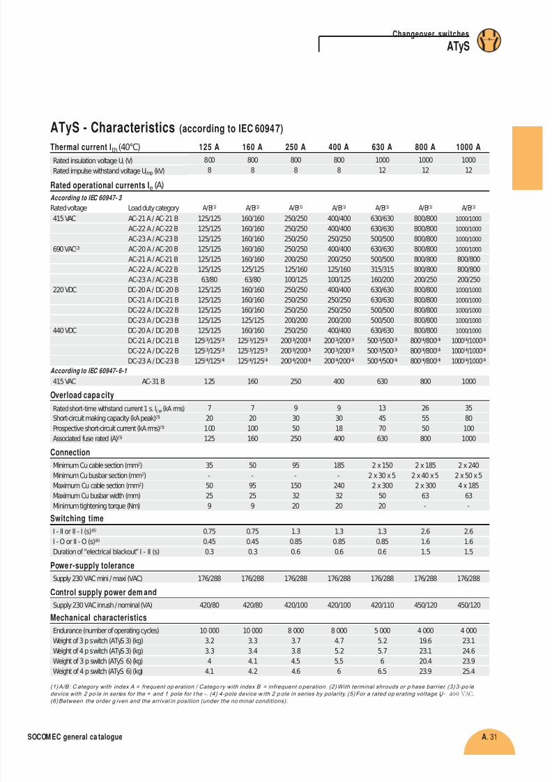
7/29/2019 Socomec ATySM Catalog En
http://slidepdf.com/reader/full/socomec-atysm-catalog-en 31/42A. 31
Changeover switches
ATyS
SOCOM EC general ca talogue
ATyS - Characteristics (according to IEC 60947)400 A 630 A 800 A
Rated operational currents Ie (A)
Rated voltage
According to IEC 60947- 3
Load duty category A/B(1) A/B(1) A/B(1)
(1) A/B: C ategory with index A = frequent op eration / Catego ry with index B = infrequent o peration. (2) With terminal shrouds or p hase barrier. (3) 3-po le
device with 2 po le in series for the + and 1 pole for t he -. (4) 4-pole device w ith 2 p ole in series by polarity. (5) For a rated op erating voltage U e = 400 VAC.(6) Between the order g iven and the arrival in position (under the nominal conditions).
Thermal current Ith(40°C)
Rated insulation voltage Ui (V)
Rated impulse withstand voltage Uimp (kV)
Overload capa cityRated short-time withstand current 1 s. Icw (kA rms)
Short-circuit making capacity (kA peak)(5)
Connection
Minimum Cu cable section (mm2)
Maximum Cu cable section (mm2)
Maximum Cu busbar width (mm)
Switching time
I - II or II - I (s)(6)
I - O or II - O (s)(6)
Powe r-supply tolerance
Supply 230 VAC mini / maxi (VAC)
Control supply power dem and
Supply 230 VAC inrush / nominal (VA)
Mechanical characteristics
Endurance (number of operating cycles)
Weight of 3 p switch (ATyS 3) (kg)
Weight of 4 p switch (ATyS 3) (kg)
A/B(1)A/B(1)
800 1000 1000
8 12 12
250 A
800
8
160 A
800
8
125 A
800
8
1000 A
1000
12
9 13 26
30 45 55
9
30
35
80
Prospective short-circuit current (kA rms)(5) 18 70 5050 100
Associated fuse rated (A)(5) 400 630 800250
7
20
100
160
7
20
100
125 1000
95 185 2 x 150 2 x 185
150 240 2 x 300 2 x 300
32 32 50 63
50
95
25
35
50
25
2 x 240
4 x 185
Minimum Cu busbar section (mm2) - - 2 x 30 x 5 2 x 40 x 5-- 2 x 50 x 5
63
Minimum tightening torque (Nm) 20 20 20 -99 -
1.3 1.3 1.3 2.60.85 0.85 0.85 1.6
0.750.45
0.750.45
2.61.6
176/288176/288176/288 176/288 176/288 176/288 176/288
420/100420/80420/80 420/100 420/110 450/120 450/120
8 000 8 000 5 000 4 000
3.7
3.8
4.7
5.2
5.2
5.7
19.6
23.1
10 000
3.3
3.4
10 000
3.2
3.3
4 000
23.1
24.6
A/B(1)A/B(1)
415 VAC AC-31 B 400 630 800 1000250160125
According to IEC 60947- 6-1
Weight of 3 p switch (ATyS 6) (kg) 4.5 5.5 6 20.44.14 23.9
Weight of 4 p switch (ATyS 6) (kg) 4.6 6 6.5 23.94.24.1 25.4
Duration of “electrical blackout” I - II (s) 0.6 0.6 0.6 1.50.30.3 1.5
125/125 160/160 250/250 400/400
125/125 160/160 250/250 400/400
125/125 160/160 250/250 250/250
125/125 160/160 250/250 400/400
125/125 160/160 200/250 200/250
125/125 125/125 125/160 125/160
63/80 63/80 100/125 100/125
125/125 160/160 250/250 400/400
125/125 160/160 250/250 250/250
125/125 160/160 250/250 250/250
125/125 125/125 200/200 200/200
125/125 160/160 250/250 400/400
125(3)/125(3) 125(3)/125(3) 200(3)/200(3) 200(3)/200(3)
125(3)/125(3) 125(3)/125(3) 200(3)/200(3) 200(3)/200(3)
125(4)/125(4) 125(4)/125(4) 200(4)/200(4) 200(4)/200(4)
415 VAC AC-21 A / AC-21 B
AC-22 A / AC-22 B
AC-23 A / AC-23 B
690 VAC(2) AC-20 A / AC-20 B
AC-21 A / AC-21 B
AC-22 A / AC-22 B
AC-23 A / AC-23 B
220 VDC DC-20 A / DC-20 B
DC-21 A / DC-21 B
DC-22 A / DC-22 B
DC-23 A / DC-23 B
440 VDC DC-20 A / DC-20 B
DC-21 A / DC-21 B
DC-22 A / DC-22 B
DC-23 A / DC-23 B
800/800 1000/1000
800/800 1000/1000
800/800 1000/1000
800/800 1000/1000
800/800 800/800
800/800 800/800
200/250 200/250
800/800 1000/1000
800/800 1000/1000
800/800 1000/1000
800/800 1000/1000
800/800 1000/1000
800(4)/800(4) 1000(4)/1000(4)
800(4)/800(4) 1000(4)/1000(4)
800(4)/800(4) 1000(4)/1000(4)
630/630
630/630
500/500
630/630
500/500
315/315
160/200
630/630
630/630
500/500
500/500
630/630
500(3)/500(3)
500(3)/500(3)
500(4)/500(4)
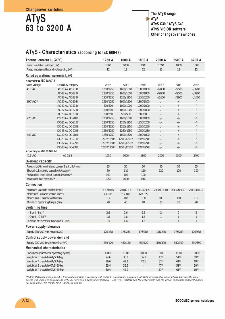
7/29/2019 Socomec ATySM Catalog En
http://slidepdf.com/reader/full/socomec-atysm-catalog-en 32/42A. 32
LChangeover switches
ATyS63 to 320 0 A
The ATyS range
ATyS
ATyS C30 / ATyS C40
ATyS VISION software
Other change over switches
SOCOMEC general catalogue
ATyS - Characteristics (according to IEC 6094 7)1800 A 2000 A 2500 A
Rated operational currents Ie (A)
Rated voltage
According to IEC 60947- 3
Load duty category A/B(1) A/B(1) A/B(1)
(1) A/B: Category w ith index A = frequent op eration / Catego ry with index B = infrequent o peration. (2) With terminal shrouds or p hase barrier. (3) 4-po le
device with 2 p ole in series by po larity. (4) For a rated o perating voltage U e = 400 VAC. (5) Between the ord er given and the arrival in position (under the nomi-
nal cond itions). (6) Weight for ATyS 3e, 6e and 6m .
Thermal current Ith(40°C)
Rated insulation voltage Ui (V)
Rated impulse withstand voltage Uimp (kV)
Overload capa cityRated short-time withstand current 1 s. Icw (kA rms)
Short-circuit making capacity (kA peak)(4)
Connection
Maximum Cu cable section (mm2)
Maximum Cu busbar width (mm)
Switching time
I - II or II - I (s)(5)
I - O or II - O (s)(5)
Power- supply tolerance
Supply 230 VAC mini / maxi (VAC)
Control supply power dem and
Supply 230 VAC inrush / nominal (VA)
Mechanical characteristics
Endurance (number of operating cycles)
Weight of 3 p switch (ATyS 3) (kg)
Weight of 4 p switch (ATyS 3) (kg)
A/B(1)A/B(1)
1000 1000 1000
12 12 12
1600 A
1000
12
1250 A
1000
12
3200 A
1000
12
50 55 55
110 120 120
50
110
55
120
Prospective short-circuit current (kA rms)(4) 100 - -100 -
Associated fuse rated (A)(4) 1800 - -1600
35
80
100
1250 -
6 x 185 6 x 185 - -
100 100 100 100
4 x 185
63
Minimum Cu cable section (mm2) 2 x 80 x 5 3 x 100 x 5 2 x 100 x 10 2 x 100 x 102 x 60 x 5 2 x 100 x 10
-
100
Minimum tightening torque (Nm) 40 40 20 2020 20
2.6 2.6 2 2
1.6 1.6 1 1
2.6
1.6
2
1
176/288176/288 176/288 176/288 176/288 176/288
450/120450/120 450/120 550/390 550/390 550/390
3 000 3 000 3 000 3 000
36.1
42.1
36.1
42.1
47(6)
57(6)
51(6)
61(6)
4 000
24.6
29.6
3 000
59(6)
69(6)
A/B(1)
415 VAC AC-31 B 1800 2000 2500 320016001250
According to IEC 60947- 6- 1
Weight of 3 p switch (ATyS 6) (kg) 36.9 - 47(6) 51(6)25.4 59(6)
Weight of 4 p switch (ATyS 6) (kg) 42.9 - 57(6) 61(6)30.4 69(6)
Duration of “electrical blackout” I - II (s) 1.6 1.6 1 11.5 1
415 VAC AC-21 A / AC-21 B
AC-22 A / AC-22 B
AC-23 A / AC-23 B
690 VAC(2) AC-20 A / AC-20 B
AC-21 A / AC-21 B
AC-22 A / AC-22 B
AC-23 A / AC-23 B
220 VDC DC-20 A / DC-20 B
DC-21 A / DC-21 B
DC-22 A / DC-22 B
DC-23 A / DC-23 B
440 VDC DC-20 A / DC-20 B
DC-21 A / DC-21 B
DC-22 A / DC-22 B
DC-23 A / DC-23 B
-/2500 -/3200
-/2500 -/3200
-/1600 -/1600
-/- -/-
-/- -/-
-/- -/-
-/- -/-
-/- -/-
-/- -/-
-/- -/-
-/- -/-
-/- -/-
-/- -/-
-/- -/-
-/- -/-
-/2000
-/2000
-/1600
-/-
-/-
-/-
-/-
-/-
-/-
-/-
-/-
-/-
-/-
-/-
-/-
1250/1250 1600/1600 1800/1800
1250/1250 1600/1600 1800/1800
1250/1250 1250/1250 1250/1250
1250/1250 1600/1600 1800/1800
800/800 1000/1000 1000/1000
800/800 1000/1000 1000/1000
200/250 500/500 500/500
1250/1250 1600/1600 1800/1800
1250/1250 1250/1250 1250/1250
1250/1250 1250/1250 1250/1250
1250/1250 1250/1250 1250/1250
1250/1250 1600/1600 1800/1800
1250(3)/1250(3) 1250(3)/1250(3) 1250(3)/1250(3)
1250(3)/1250(3) 1250(3)/1250(3) 1250(3)/1250(3)
1250(3)/1250(3) 1250(3)/1250(3) 1250(3)/1250(3)
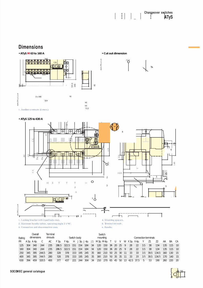
7/29/2019 Socomec ATySM Catalog En
http://slidepdf.com/reader/full/socomec-atysm-catalog-en 33/42A. 33
Changeover switches
ATyS
SOCOM EC general ca talogue
Dimensions• ATyS M63 to 160 A • Cut out dimension
1
340
17610452
324
116
2 4 5
1 3 1 ,
5
4 5
1 4 3
3 5 0
2613
73,5
53
46
186 x M6
a t y s m
_ 0 3 4
_ a_
1_
x_
c a
t
324
4 7
a t y s m
_ 7 0 9
_ a
_ 1
_ c a
t
10
W
U
M
J
J 1
X T T T 11
C
H
Z2
Z1
10.5 Y Y
85
48
F
A
1 2 0
1 4 0
2 7 0
V
2 2 3
1 1 9
=
F i x .
1 8 0
F i x .
1 9 5
B A
C A
C A
A A
A C
1 0 1
=
Ø7
Ø9
F i x .
1 8 0
F i x .
1 9 5 1
32
3
3
4
5
6
C A
W
U a
t y s
_ 0 1 8
_ e
_ 1
_ x_ c a
t
1. Locking brac ket with 3 pad locks max.
2. Maximum ha ndle radius, operating ang le 2 x 90° .
3. Connection and disconnection area.
4. Mounting sp ac ers.
5. Termina l sh rouds .
6. Handle.
1. Auxiliary c onta cts (2 ma x.).
C
244244
244.5
244.5
320.5
Rating(A)
Overalldimensions
Terminalshrouds Switch body
Switchmounting Connection terminals
A 3p. A 4p. AC F 3p. F 4p. H J 3p. J 4p. J 1 M 3p. M 4p. T U V W X 3p. X 4p. Y Z1 Z2 AA BA CA
125 304 340 235 286.5 322.5 151 154 184 34 120 150 36 20 25 9 28 22 3.5 38 134 135 115 10160 304 340 235 286.5 322.5 151 154 184 34 120 150 36 20 25 9 28 22 3.5 38 134 135 115 10
250 345 395 280 328 378 153 195 245 35 160 210 50 25 30 11 33 33 3.5 39.5 134.5 160 130 15
400 345 395 280 328 378 153 195 245 35 160 210 50 35 35 11 33 33 3.5 39.5 134.5 170 140 15
630 394 459 400 377 437 221 244 304 34 210 270 65 45 50 13 42.5 37.5 5 53 190 260 220 20
• ATyS 125 to 630 A
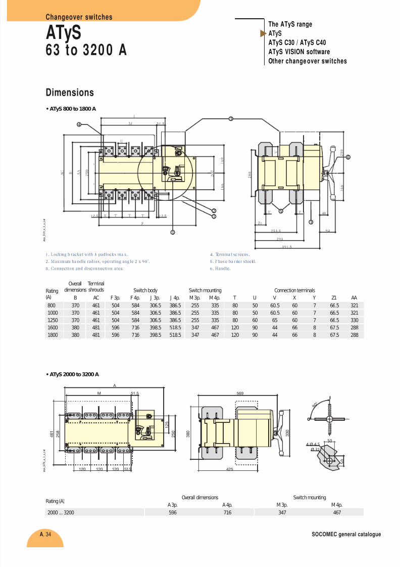
7/29/2019 Socomec ATySM Catalog En
http://slidepdf.com/reader/full/socomec-atysm-catalog-en 34/42A. 34
LChangeover switches
ATyS63 to 320 0 A
The ATyS range
ATyS
ATyS C30 / ATyS C40
ATyS VISION software
Other change over switches
SOCOMEC general catalogue
Dimensions
M 51,5
53,5120120120
A
2 5 0
2 5 8
4 6 1
569
425
3 8 0
1 2 5
3 3 0
0
I
9 0 °
504 Ø 4.5
Ø 31
5 0
a t y s
_ 6 7 8
_ a
_ 1
_ x_ c a
t
Rating (A)Overall dimensions Switch mounting
A 3p. M 3p. M 4p.
2000 ... 3200 596
A 4p.
716 347 467
• ATyS 2000 to 3200 A
F
12.5
=
2 0 7
1 6 9
1 6 6
2 8 0
2 5 0
1 6 6
V
=
2 5 0
A A
12.5
391.5
293
253.5
Z1
Y Y 48
94
X
M 51.5
J
T T T
1
3
B A C
2
3
3
4
5
6
U
a t y s
_ 0 1 9
_ e
_ 1
_ x_ c a
t
1. Locking b racket with 3 padlocks ma x.
2. Maximum ha ndle radius, operating ang le 2 x 90°.
3. Connection and disconnection area.
4. Termina l sc reens .
5. P has e ba rrier shield.
6. Handle.
Rating(A)
Overall
dimensions
Terminal
shrouds Switch body Switch mounting Connection terminalsB AC F 3p. F 4p. J 3p. J 4p. M 3p. M 4p. T U V X Y Z1 AA
800 370 461 504 584 306.5 386.5 255 335 80 50 60.5 60 7 66.5 321
1000 370 461 504 584 306.5 386.5 255 335 80 50 60.5 60 7 66.5 321
1250 370 461 504 584 306.5 386.5 255 335 80 60 65 60 7 66.5 330
1600
1800
380
380
481
481
596
596
716
716
398.5
398.5
518.5
518.5
347
347
467
467
120
120
90
90
44
44
66
66
8
8
67.5
67.5
288
288
• ATyS 800 to 1800 A
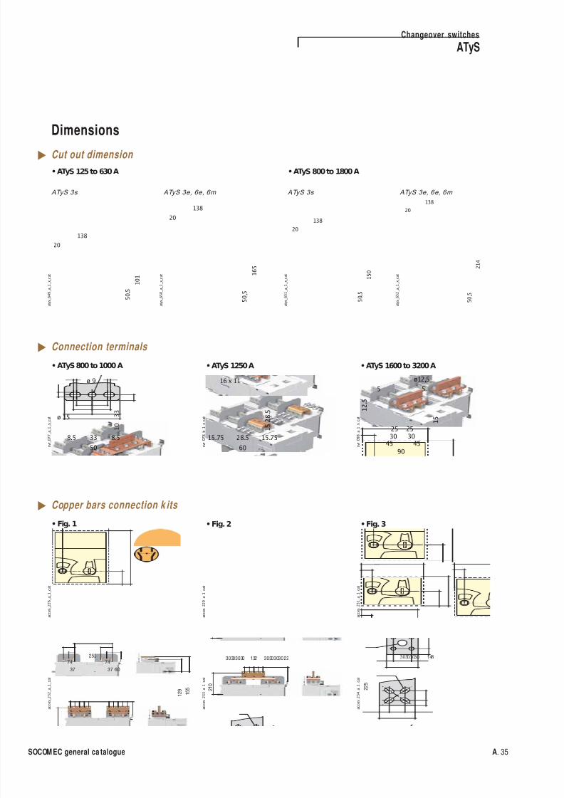
7/29/2019 Socomec ATySM Catalog En
http://slidepdf.com/reader/full/socomec-atysm-catalog-en 35/42A. 35
Changeover switches
ATyS
SOCOM EC general ca talogue
Dimensions
33 8.58.5
50
3 3
1 0
ø 9
ø 15
s v r_
0 7 7
_ a
_ 1
_ x_ c a
t
16 x 11
60
28.5 15.7515.75
2 8
. 5
1 5
s v r_
0 7 8
_ b
_ 1
_ x_ c a
t
1 5
5 5
1 2
, 5
25 253030
4545
90
ø12,5
s v r_
0 9 8
_ a
_ 1
_ x_ c a
t
Connection terminals L
Cut out dimension L
• ATyS 800 to 1000 A • ATyS 1250 A • ATyS 1600 to 3200 A
252
74
37
74
37 60
1 2 9
1 5 5
30303030 132 30303030 22
2 1 0
30303030 148
2 2 5
a c c e s
_ 2 2 6
_ a
_ 1
_ c a
t
a c c e s
_ 2 3 2
_ a
_ 1
_ c a
t
a c c e s
_ 2 3 3
_ a
_ 1
_ c a
t
a c c e s
_ 2 3 4
_ a
_ 1
_ c a
t
a c c e s
_ 2 2 9
_ a
_ 1
_ c a
t
a c c e s
_ 2 3 1
_ a
_ 1
_ c a
t
Copper bars connection k its L
• Fig. 1 • Fig. 2 • Fig. 3
a t y s
_ 6 4 9
_ a
_ 1
_ x
_ c a
t
a t y s
_ 6 5 0
_ a
_ 1
_ x
_ c a
t
5 0
, 5
20
138
1 0 1
5 0
, 5
20
138
1 6
5
ATyS 3s ATyS 3e, 6e, 6m
a t y s
_ 6 5 1
_ a
_ 1
_ x
_ c a
t
a t y s
_ 6 5 2
_ a
_ 1
_ x
_ c a
t
5 0
, 5
20
138
1 5 0
5 0
, 5
20
138
2 1 4
ATyS 3s ATyS 3e, 6e, 6m
• ATyS 125 to 630 A • ATyS 800 to 1800 A
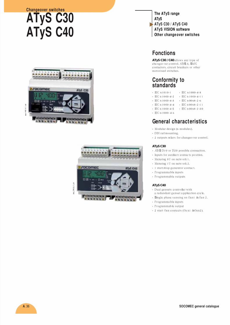
7/29/2019 Socomec ATySM Catalog En
http://slidepdf.com/reader/full/socomec-atysm-catalog-en 36/42A. 36
a t y s
_ 4 4 8
_ b
_ 1
_ c a
t
Changeover switches
ATyS C30ATyS C40
SOCOMEC general catalogue
a t y s
_ 5 9 9
_ b
_ 1
_ c a
t
FonctionsATyS C30 / C40allows any type of
cha ng eo ver c ontrol: ATyS 3, SMV,
contactors, circuit breakers or other
motorised switches.
Conformity tostandards• IEC 61010-1 • IEC 61000-4-8
• IEC 61000-4-2 • IEC 61000-4-11
• IEC 61000-4-3 • IEC 60068-2-6
• IEC 61000-4-4 • IEC 60068-2-11
• IEC 61000-4-5 • IEC 60068-2-30
• IEC 61000-4-6
General characteristics• Modular des ign (6 modules).
• DIN rail mounting.
• 2 outputs relays for changeo ver control.
ATyS C30
• ATyS D10 or D20 possible connection.
• Inputs for auxilia ry contac ts po sition.
• Metering 3U on netw ork 1.
• Metering 1U on netw ork 2.
• 1 start/stop g enerator contac t.
• Programma ble inputs
• Programmable outputs
ATyS C40
• Dual gensets controller with
a redundant g enset a pplica tion cyc le.
• Single phase s ensing on Gen1 &Gen 2.
• Programma ble inputs
• Programmab le output
• 2 start Gen conta cts (Ge n1 &Gen2).
L
The ATyS range
ATyS
ATyS C30 / ATyS C40
ATyS VISION software
Other change over switches
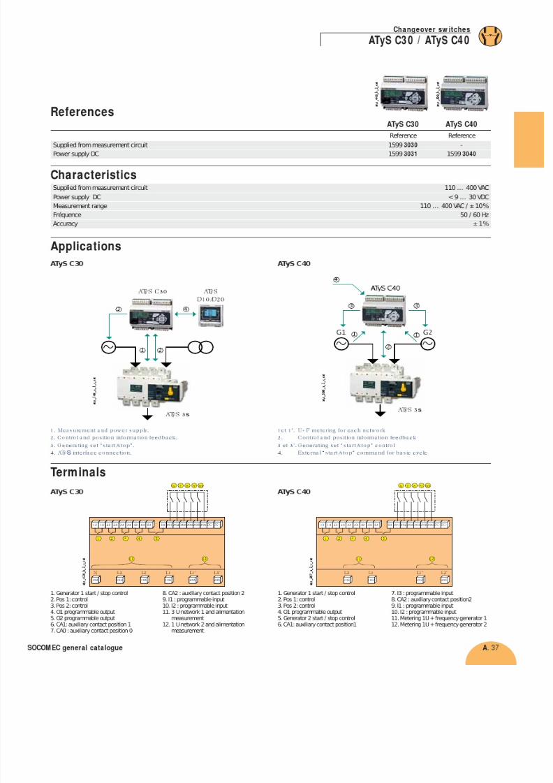
7/29/2019 Socomec ATySM Catalog En
http://slidepdf.com/reader/full/socomec-atysm-catalog-en 37/42
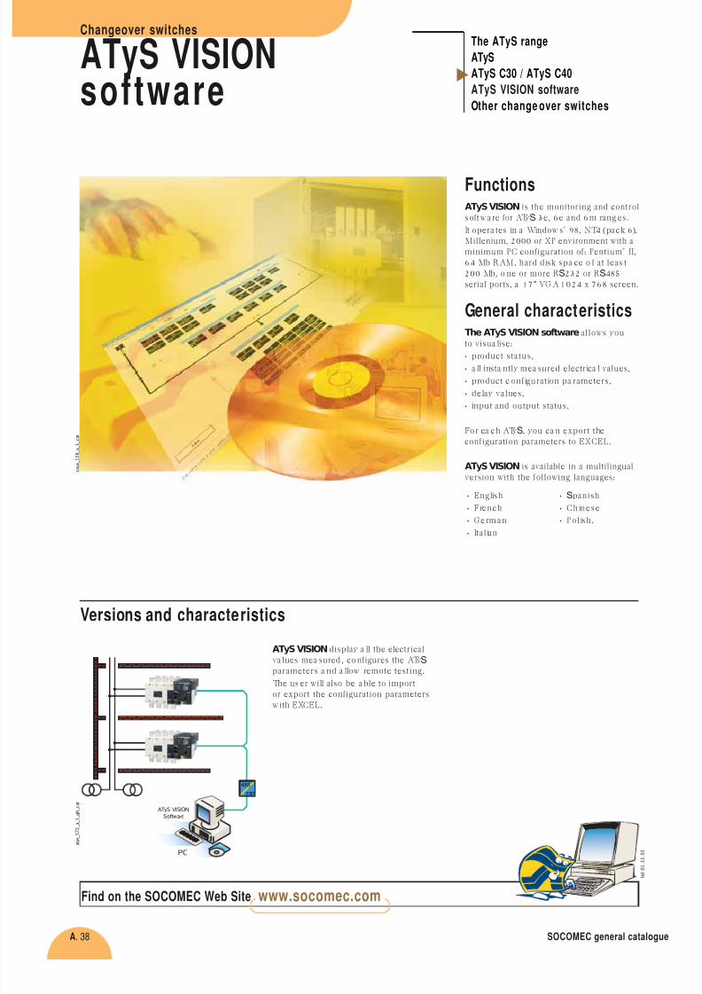
7/29/2019 Socomec ATySM Catalog En
http://slidepdf.com/reader/full/socomec-atysm-catalog-en 38/42A. 38
c o u v
_ 1 2 8
_ a
_ 1
_ c a
t
FunctionsATyS VISION is the monitoring and control
soft w a re for ATyS 3e, 6e and 6m rang es.
It opera tes in a Window s ® 98, NT4 (pack 6),
Millenium, 2000 or XP environment with a
minimum PC configuration of: Pentium® II,
64 Mb RAM, hard disk spa ce o f at leas t
200 Mb, o ne or more RS232 or RS485
serial ports, a 17” VG A 1024 x 768 screen.
General characteristicsThe ATyS VISION software allows you
to visua lise:
• product status,
• a ll insta ntly mea sured electrica l values,
• product c onfiguration pa rameters,
• delay values,
• input and output status.
For ea ch ATyS, you ca n export the
configuration parameters to EXCEL.
ATyS VISION is available in a multilingual
version with the following languages:
• English
• French• German
• Italian
• Spanish
• Chinese• Polish.
Versions and characteristics
ATyS VISION display a ll the electrical
va lues mea sured , co nfigures the ATySparameters a nd a llow remote testing.
The us er will also be a ble to import
or export the configuration parameters
w ith EXCEL.
Changeover switches
ATyS VISIONsoftware
SOCOMEC general catalogue
C O N T R O
L V I S I O
N ® 1
L o g ic i e l d e su p e r v is io n D I R I S
® e t C O
U N T I S
®
485
232
Software
ATyS VISION
PC
a t y s
_ 5 7 2
_ a
_ 1
_ g
b_
c a
t
Find on the SOCOMEC Web Site www.socomec.com
b d
_ 0 1
_ 1 3
_ 0 3
L
The ATyS range
ATyS
ATyS C30 / ATyS C40
ATyS VISION software
Other change over switches
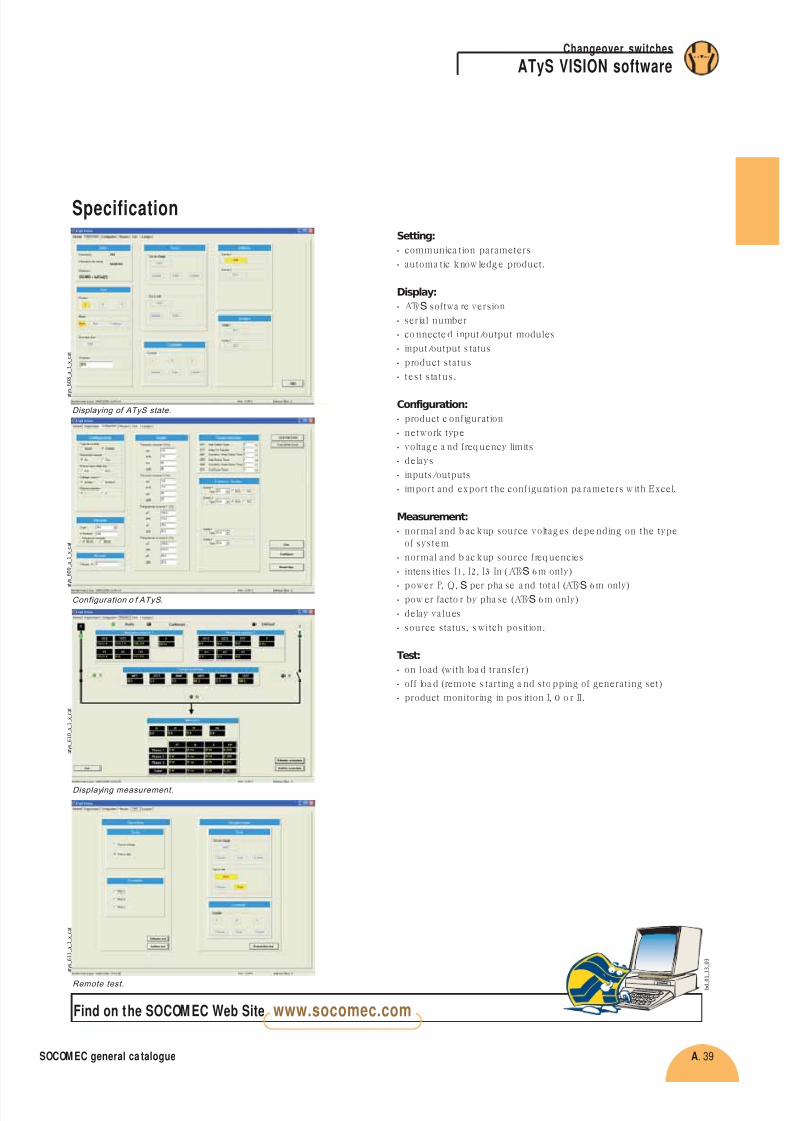
7/29/2019 Socomec ATySM Catalog En
http://slidepdf.com/reader/full/socomec-atysm-catalog-en 39/42A. 39
Changeover switches
ATyS VISION software
SpecificationSetting:
• communica tion parameters
• automa tic know ledg e product.
Display:
• ATyS softwa re version
• serial number
• co nnecte d input/output modules
• input/output s tatus
• product status
• test s tatus.
Configuration:
• product c onfiguration
• network type
• voltag e a nd freq uency limits
• delays
• inputs/outputs
• import and export the configuration pa rameters w ith Excel.
Measurement:
• normal and b ac kup source voltag es depe nding on the type
of system
• normal and b ac kup source freq uencies
• intens ities I1, I2, I3 In (ATyS 6m only)• power P, Q, S per pha se a nd tot a l (ATyS 6m only)
• pow er facto r by pha se (ATyS 6m only)
• delay values
• source status, s witch position.
Test:
• on load (with loa d transfer)
• off loa d (remote s tarting a nd sto pping of generating set)
• product monitoring in pos ition I, 0 o r II.
SOCOM EC general ca talogue
a t y s
_ 6 0
8_
a_
1_
x_
c a
t
Displaying of ATyS state.
a t y s
_ 6 0
9_
a_
1_
x_ c a
t
Configuration o f ATyS.
a t y s
_ 6 1 1
_ a
_ 1
_ x_ c a
t
a t y s
_ 6 1 0
_ a
_ 1
_ x_ c a
t
Displaying measurement.
Remote test.
Find on the SOCOM EC Web Site www.socomec.com
b d
_ 0 1
_ 1 3
_ 0 3
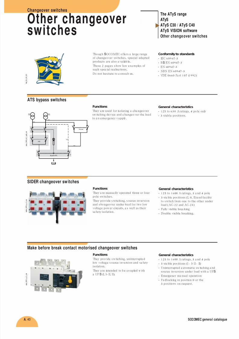
7/29/2019 Socomec ATySM Catalog En
http://slidepdf.com/reader/full/socomec-atysm-catalog-en 40/42A. 40
b d
_ 0 1
_ 0 1
_ 0 3
Conformity to standards
• IEC 60947-3• BS EN 60947-3
• EN 60947-3
• NBN EN 60947-3
• VDE 0660 Pa rt 107 (1992)
Changeover switches
Other changeoverswitches
SOCOMEC genera l catalogue
Thoug h SOCOMEC o ffers a large range
of changeover switches, special adaptedproducts are also a vailab le.
These 2 pag es s how few exa mples of
such spec ial realisa tions.
Do not hesitate to c onsult us.
ATS bypass switches
Functions
They a re used for isolating a cha ngeover
sw itching device and c hangeo ver the loa dto a n emergency s upply.
General characteristics
• 125 to 630 A ratings, 4 po le only
• 3 stable positions.
ATS
T2 T1
S2
S2
S1
III3
I2I1
By pass ATS
Sircover
S2
Load
a t y s
_ 5 6 9
_ b
_ 1
_ g
b_
c a
t
Make before break contact motorised changeover switches
a t y s
_ 0 0 3
_ a
_ 2
_ c a
t
Functions
They provide s w itching, uninterrupte d
low voltag e s ource inversion and sa fety
isolation.
They a re intended to b e co upled w ith
a UP S (I, I+ II, II).
General characteristics
• 125 to 1600 A ratings, 3 a nd 4 pole
• 3 sta ble pos itions (I - I+ II - II)
• Uninterrupted a utomatic sw itching a nd
source inversion under load with a UPS
• Emergency ma nual operation
• Pa dlocking in position 0 or the
3 positions on request.
SIDER changeover sw itches
s i d e r_
0 7 0
_ a
_ 1
_ c a
t
Functions
They a re manua lly operated three or four-
pole switches.
They provide s witching, s ource inversion
and cha ngeover under loa d for two low
voltag e pow er circuits, a s well as their
sa fety isolation.
General characteristics
• 125 to 1600 A ratings, 3 a nd 4 pole
• 3 sta ble pos itions (I, 0, II) a nd fa cility
to s witch from one to the other under
load (AC-22 and AC-23)
• Fully visible brea king
• Double visible breaking.
L
The ATyS range
ATyS
ATyS C30 / ATyS C40
ATyS VISION software
Other change over switches
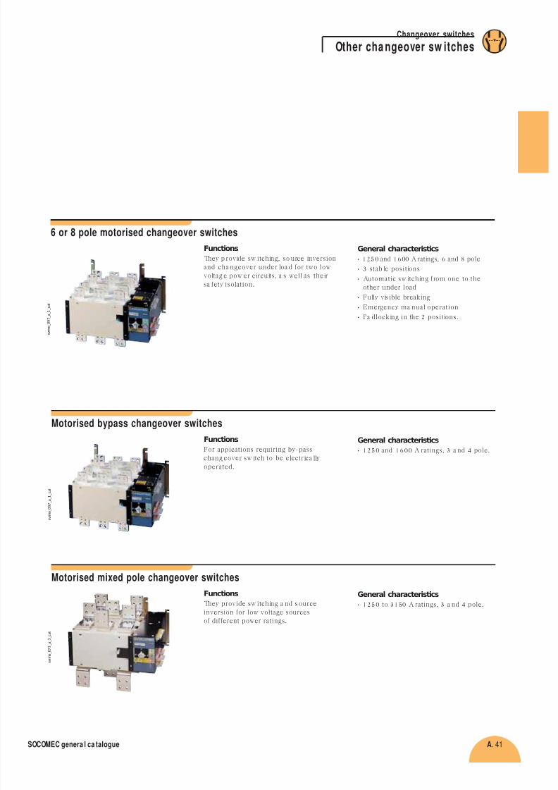
7/29/2019 Socomec ATySM Catalog En
http://slidepdf.com/reader/full/socomec-atysm-catalog-en 41/42A. 41
Changeover switches
Other cha ngeover sw itches
6 or 8 pole motorised changeover switches
s v r m o
_ 0 9 7
_ a
_ 1
_ c a
t
Functions
They p rovide sw itching, so urce inversion
and cha ngeover under loa d for two low voltag e pow er circuits, a s well as their
sa fety isolation.
SOCOMEC genera l ca talogue
General characteristics
• 1250 and 1600 A ratings, 6 and 8 pole
• 3 stab le positions• Automatic sw itching from one to the
other under load
• Fully vis ible breaking
• Emergency ma nual operation
• Pa dlocking in the 2 positions.
Motorised bypass changeover switches
s v r m o
_ 0 9 7
_ a
_ 1
_ c a
t
Functions
For appications requiring by-pass
chang eover sw itch to be electrica lly
operated.
Motorised mixed pole changeover switches
s v r m o
_ 0 7 3
_ a
_ 3
_ c a
t
Functions
They provide sw itching a nd s ource
inversion for low voltage sources
of different power ratings.
General characteristics
• 1250 and 1600 A ratings, 3 a nd 4 pole.
General characteristics
• 1250 to 3150 A ratings, 3 a nd 4 pole.
7/29/2019 Socomec ATySM Catalog En
http://slidepdf.com/reader/full/socomec-atysm-catalog-en 42/42
H E A D O F F I C E
SOCOMEC GROUP
S.A . SOC OM EC cap i ta l 1 1 0 1 4 3 0 0 €
R.C .S . S tr asbour g B 548 500 149
B.P. 60010 - 1 , r ue de W esthouse - F- 67235 Ben fe ld C edex - FRANCE
I N T E R N A T I O N A L
S A L E S D E P A R T M E N T
SOCOMEC
1, rue de Westhouse - B.P. 60010F - 67235 Ben fe ld Ced ex - FRANCE
Te l. +33 (0 ) 3 88 57 41 4 1 - Fax +33 (0 ) 3 88 74 08 0 0
Socomec worldwide
I N E U R O P E
BELGIUM
SO C O M EC BEL G IE
B - 1190 Brusse l
Te l. +32 (0 )2 340 02 30 - Fax +32 (0 )2 346 28 99
be .scp .o rder@socomec .com
FRANCE
S O C O M E C
F - 67235 B en fe ld Cedex
Te l. +33 (0 )3 88 57 41 41 - Fax +33 (0 )3 88 74 0 8 00
scp .vex@socomec .com
GERMANY
SOCOMEC Scha l tge rä te GmbH
D - 35510 Bu tzbach
Te l. +49 (0 ) 6033 98 07 0 - Fax +49 (0 ) 6033 98 0 7 13in fo@socomec .com
ITALY
SOCOMEC Elettrotecnica Sr l -
20098 S. Giul iano Milanese (MI)
Te l. + 3 9 0 2 9 8 4 9 8 2 1 - F ax + 3 9 0 2 9 8 2 4 3 3 1 0
SPAIN
SOCOMEC ELECTRO, S.L .
E - 08310 Argentona (Barcelona)
Te l . +34 93 741 60 67 - Fax . +34 93 757 49 52
es .scp . in fo@socomec .com
THE NETHERLANDS
SO C O M EC B .V.
N L - 3 9 9 2 D E H o u te n
Te l. +31 (0 )30 63 71 504 - Fax +31 (0 )30 6 3 72 166
UNITED KINGDOM
SO C O M EC L td
UK - Knowl Piece - Wilbury Way
Hitchin Hertfordshire SG 4 O TY
Te l. +44 (0 )1462 44 0033 - Fax +44 (0 )1462 4311 43
sa les .uk .scp@socomec .com
I N A S I A
CHINA
SO C O M EC C H IN A
CN - 2 0030 P.R .C Shangha i
Te l. + 8 6 2 1 5 2 9 8 9 5 5 5 - F a x + 8 6 2 1 6 2 2 8 3 4 6 8
socomec@socomec-shangha i .com
SOUTH EAST ASIA
SOCOMEC THAILAND
TH - Bangkok
Te l . +66 2 982 80 51 - Fax +66 2 982 80 50
scp@socomec . tha i .com
I N M I D D L E E A S T
UNITED ARAB EMIRATES
SOCOMEC Midd le Eas t
P.O. Box : 261 282
LOB 14 - 123 - Jebel Al i Free Zone
Dubai, U.A.E.
Te l. + 9 7 1 4 8 8 1 1 6 2 3 - F a x + 9 7 1 4 8 8 1 9 8 8 7
sa les .ae .scp@socomec .com
Related Documents