SEMINOLE INFORMATION MANUAL Seminole PA-44-180 HANDBOOK PART NO 761 662

Welcome message from author
This document is posted to help you gain knowledge. Please leave a comment to let me know what you think about it! Share it to your friends and learn new things together.
Transcript

SEMINOLEINFORMATION
MANUAL
SeminolePA-44-180
HANDBOOKPART NO 761 662

PublishedbyPUBLICATIONSDEPARTMENT
Piper AircraftCorporationIssued: March23, 1978
REPORT: VB-860ii
APPLICABILITY
Application of this handbook is limited to the specific Piper PA-44-180model airplane designated by serial number and registration number on theface of the title page of this handbook.
This handbook cannot be used for operational purposes unless kept ina current status.
REVISIONS
The information compiled in the Pilot's Operating Handbook will bekept current by revisions distributed to the airplane owners.
Revision material will consist of information necessary to update thetext of the present handbook and/or to add information to cover addedairplane equipment.
I. Revisions
Revisions will be distributed whenever necessary as complete pagereplacements or additions and shall be inserted into the handbook inaccordance with the instructions given below:
1. Revision pages will replace only pages with the same page number.2. Insert all additional pages in proper numerical order within each
section.3. Page numbers followed by a small letter shall be inserted in direct
sequence with the same common numbered page.
II. Identification of Revised Material
Revised text and illustrations shall be indicated by a black verticalline along the outside margin of the page, opposite revised, added ordeleted material. A line along the outside margin of the page opposite thepage number will indicate that an entire page was added
REPORT: VB-860lii
Black lines will indicate only current revisions with changes andadditions to or deletions of existing text and illustrations. Changes incapitalization, spelling, punctuation or the physical location of material ona page will not be identified.
ORIGINAL PAGES ISSUED
The original pays issued for this handbook prior to revision are givenbelow:
Title, ii through vii, 1-1 through 1-21, 2-1 through 2-10, 3-1 through3-21, 4-1 through 4-27, 5-1 through 5-33, 6-1 through6-50, 7-1 through7-34,8-1 through 8-17, 9-1 through 9-22, and 10-1 through 10-3.
REPORT: VB-860iv
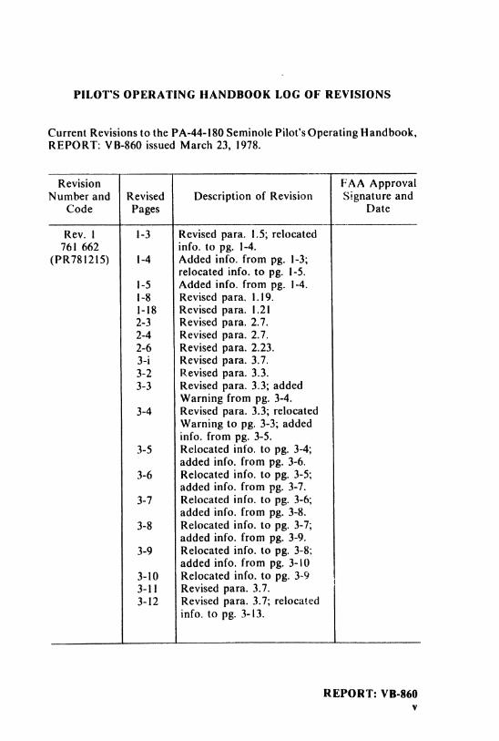
PILOT'S OPERATING HANDBOOK LOG OF REVISIONS
Current Revisions to the PA-44-180 Seminole Pilot'sOperating Handbook,REPORT: VB-860 issued March 23, 1978.
Revision FAA ApprovalNumber and Revised Description of Revision Signature and
Code Pages Date
Rev. I 1-3 Revised para. 1.5; relocated761 662 info. to pg. 1-4.
(PR7812l5) 1-4 Added info. from pg. 1-3;relocated info. to pg. 1-5.
1-5 Added info. from pg. 1-4.I-8 Revised para. 1.19.1-18 Revised para. 1.212-3 Revised para. 2.7.2-4 Revised para. 2.7.2-6 Revised para. 2.23.3-i Revised para. 3.7.3-2 Revised para. 3.3.3-3 Revised para. 3.3; added
Warning from pg. 3-4.3-4 Revised para. 3.3; relocated
Warning to pg. 3-3; addedinfo. from pg. 3-5.
3-5 Relocated info. to pg. 3-4;added info. from pg. 3-6.
3-6 Relocated info. to pg. 3-5;added info. from pg. 3-7.
3-7 Relocated info. to pg. 3-6;added info. from pg. 3-8.
3-8 Relocated info. to pg. 3-7;added info. from pg. 3-9.
3-9 Relocated info. to pg. 3-8:added info. from pg. 3-10
3-10 Relocated info. to pg. 3-93-11 Revised para. 3.7.3-12 Revised para. 3.7; relocated
info. to pg. 3-13.
REPORT: VB-860v
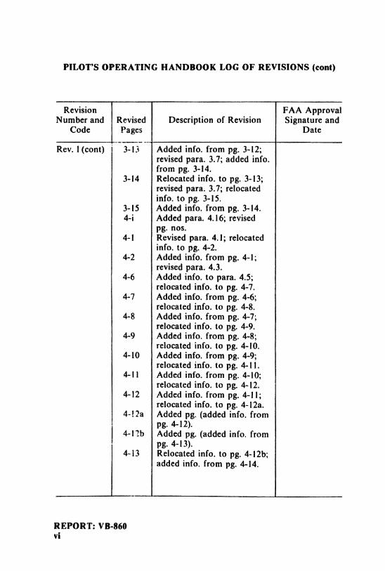
PILOT'S OPERATING HANDBOOK LOG OF REVISIONS (cont)
Revision FAA ApprovalNumber and Revised Description of Revision Signature and
Code Pages Date
Rev. 1(cont) 3-13 Added info. from pg. 3-12;revised para. 3.7; added info.from pg. 3-14.
3-14 Relocated info. to pg. 3-13;revised para. 3.7; relocatedinfo. to pg. 3-15.
3-15 Added info. from pg. 3-14.4-i Added para. 4.16; revised
pg. nos.4-1 Revised para. 4.1; relocated
info. to pg. 4-2.4-2 Added info. from pg. 4-1;
revised para. 4.3.4-6 Added info. to para. 4.5;
relocated info. to pg. 4-7.4-7 Added info. from pg. 4-6;
relocated info. to pg. 4-8.4-8 Added info. from pg. 4-7;
relocated info. to pg. 4-9.4-9 Added info. from pg. 4-8;
relocated info. to pg. 4-10.4-10 Added info. from pg. 4-9;
relocated info. to pg. 4-11.4-11 Added info. from pg. 4-10;
relocated info. to pg. 4-12.4-12 Added info. from pg. 4-11;
relocated info. to pg. 4-12a.4-!2a Added pg. (added info. from
pg. 4-12).4-12b Added pg. (added info. from
pg. 4-13).4-13 Relocated info. to pg. 4-12b;
added info. from pg. 4-14.
REPORT: VB-860vi
PILOT'S OPERATING HANDBOOK LOG OF REVISIONS (cont)
Revision FAA ApprovalNumber and Revised Description of Revision Signature and
Code Pages Date
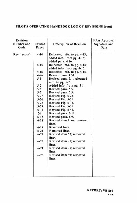
Rev. 1(cont) 4-14 Relocated info. to pg. 4-13,added info. from pg. 4-15;added para. 4.16.
4-15 Relocated info. to pg. 4-14;added info. from pg. 4-16.
4-16 Relocated info. to pg. 4-15.4-26 Revised para. 4.51.5-1 Revised para. 5.1; relocated
info. to pg. 5-2.5-2 Added info. from pg. 5-1.5-6 Revised para. 5.5.5-7 Revised para. 5.5.5-22 Revised Fig. 5-23.5-26 Revised Fig. 5-3i.5-27 Revised Fig. 5-33.5-28 Revised Fig. 5-35.5-3I Revised Fig. 5-41.6-i Revised para. 6.11.6-15 Revised para. 6.9.6-18 Revised item I and removed
lines.6-19 Removed lines.6-21 Removed lines.6-22 Revised item 53; removed
lines.6-23 Revised item 71; removed
lines.6-24 Revised item 77; removed
lines.6-25 Revised item 91; removed
lines.
REPORT: VB-860vi-a
PILOT'S OPERATING HANDBOOK LOG OF REVISIONS (cont)
Revision FAA ApprovalNumber and Revised Description of Revision Signature and
Code Pages Date
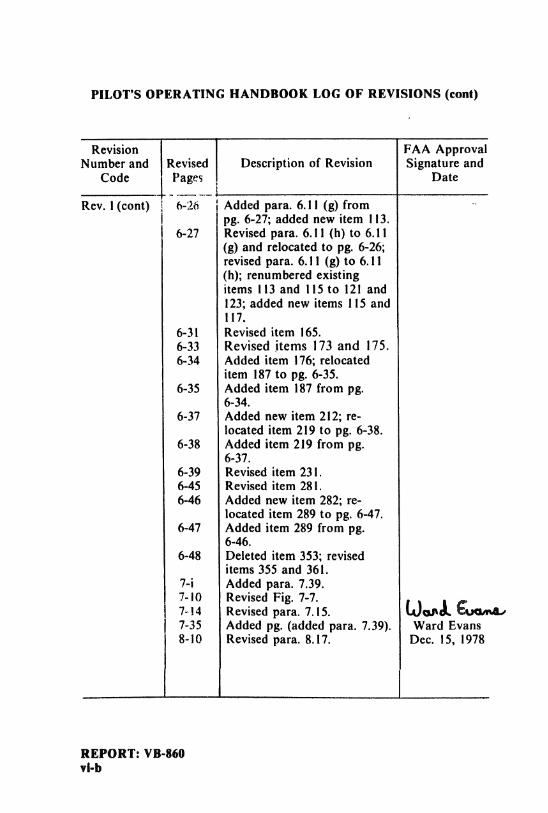
Rev. 1(cont) 6-26 Added para. 6.11 (g) frompg. 6-27; added new item I 13.
6-27 Revised para. 6.11 (h) to 6.11(g) and relocated to pg. 6-26;revised para. 6.11 (g) to 6.11(h); renumbered existingitems 113 and 115 to 121 and123; added new items I 15 and117.
6-31 Revised item 165.6-33 Revised items 173 and 175.6-34 Added item 176; relocated
item 187 to pg. 6-35.6-35 Added item 187 from pg.
6-34.6-37 Added new item 212; re-
located item 219 to pg. 6-38.6-38 Added item 219 from pg.
6-37.6-39 Revised item 231.6-45 Revised item 281.6-46 Added new item 282; re-
located item 289 to pg. 6-47.6-47 Added item 289 from pg.
6-46.6-48 Deleted item 353; revised
items 355 and 361.7-i Added para. 7.39.7-10 Revised Fig. 7-7.7-14 Revised para. 7.15.
OoA
7-35 Added pg. (added para. 7.39). Ward Evans8-10 Revised para. 8.17. Dec. 15, 1978
REPORT: VB-860vi-b
PILOT'S OPERATING HANDBOOK LOG OF REVISIONS (cont)
Revision FAA ApprovalNumber and Revised Description of Revision Signature and
Code Pages Date
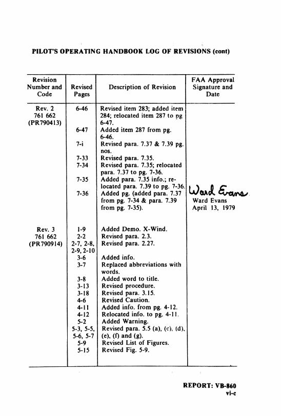
Rev. 2 6-46 Revised item 283; added item761 662 284; relocated item 287 to pg
(PR790413) 6-47.6-47 Added item 287 from pg.
6-46.7-i Revised para. 7.37 & 7.39 pg.
nos.7-33 Revised para. 7.35.7-34 Revised para. 7.35; relocated
para. 7.37 to pg. 7-36.7-35 Added para. 7.35 info.; re-
7-36Aocadteddppara 7 39 tpopg. 376.
from pg. 7-34 & para. 7.39 Ward Evansfrom pg. 7-35). April 13, 1979
Rev. 3 1-9 Added Demo. X-Wind.761 662 2-2 Revised para. 2.3.
(PR790914) 2-7, 2-8, Revised para. 2.27.2-9, 2-10
3-6 Added info.3-7 Replaced abbreviations with
words.3-8 Added word to title.3-13 Revised procedure.3-18 Revised para. 3.15.4-6 Revised Caution.4-11 Added info. from pg. 4-12.4-12 Relocated info. to pg. 4-11.5-2 Added Warning.
5-3, 5-5, Revised para. 5.5 (a), (c). (d),5-6, 5-7 (e), (f) and (g).
5-9 Revised List of Figures.5-15 Revised Fig. 5-9.
REPORT: VB-860vi-c
PILOT'S OPERATING HANDBOOK LOG OF REVISIONS (cont)
Revision FAA ApprovalNumber and Revised Description of Revision Signature and
Code Pages Date
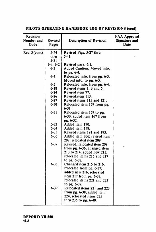
Rev. 3 (cont) 5-24 Revised Figs. 5-27 thruthru 5-41.5-3!
6-1, 6-2 Revised para. 6.1.6-3 Added Caution. Moved info.
to pg. 6-4.6-4 Relocated info. from pg. 6-3.
Moved info. to pg. 6-5.6-5 Relocated info. from pg. 6-4.6-18 Revised items 1, 3 and 5.6-24 Revised item 77.6-26 Revised. item 113.6-27 Revised items 115 and 121.6-30 Relocated item 159 from pg.
6-31.6-31 Relocated item 159 to pg.
6-30; added item 167 frompg. 6-32.
6-32 Added item 170.6-34 Added item 178.6-35 Revised items 191 and 193.6-36 Added item 206; revised item
207; relocated item 209.6-37 Revised, relocated item 209
from pg. 6-36; changed item213 to 214; added new 213;relocated items 215 and 217to pg. 6-38.
6-38 Changed item 215 to 216,relocated from pg. 6-37;added new 216; relocateditem 217 from pg. 6-37;relocated items 221 and 223to pg. 6-39.
6-39 Relocated items 221 and 223from pg. 6-38; added item224; relocated items 225thru 235 to pg. 6-40.
REPORT: VB-860vi-d
PILOT'S OPERATING HANDBOOK LOG OF REVISIONS (cont)Revision FAA Approval
Number and Revised Description of Revision Signature andCode Pages Date
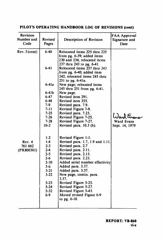
Rev. 3 (cont) 6-40 Relocated items 225 thru 235from pg. 6-39; added items230 and 234; relocated items237 thru 243 to pg. 6-41.
6-41 Relocated items 237 thru 243from pg. 6-40; added item242; relocated items 245 thru25 I to pg. 64 la.
6-41a New page; relocated items245 thru 251 from pg. 6-41.
6-41b New page.6-47 Revised item 291.6-48 Revised item 355.7-9 Revised para. 7.9.7-11 Revised Figure 7-9.7-25 Revised para. 7.23,7-26 Revised Figure 7-25.7-28 Revised Figure 7-27. Ward Evans
10-2 Revised para. 10.3 (h). Sept. 14, 1979
1-2 Revised Figure 1-1.Rev. 4 1-4 Revised para. 1.7, 1.9 and I.11.
761 662 2-3 Revised para. 2.7(PR800301) 2-4 Revised para. 2.11.
2-5 Revised para. 2.13.2-6 Revised para. 2.23.2-10 Added serial number effectivity3-ii Added para. 3.37.3-21 Added para. 3.37.3-22 New page, contin. para.
3.37.5-23 Revised Figure 5-25.5-24 Revised Figure 5-27.5-32 Revised Figure 5-43.6-9 Moved revised Figure 6-9
to pg. 6-10.
REPORT: VB-860vi-e
PILOT'S OPERATING HANDBOOK LOG OF REVISIONS (cont)
Revision FAA ApprovalNumber and Revised Description of Revision Signature and
Code Pages Date
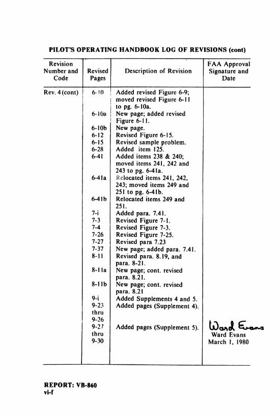
Rev.4(cont) 6-10 Added revised Figure 6-9;moved revised Figure 6-11to pg. 6-10a.
6-10a New page; added revisedFigure 6-1 1.
6-10b New page.6-12 Revised Figure 6-15.6-15 Revised sample problem.6-28 Added item 125.6-41 Added items 238 & 240;
moved items 241, 242 and243 to pg. 6-41a.
6-4la Relocated items 241, 242,243; moved items 249 and251 to pg. 6-41b.
6-41b Relocated items 249 and251.
7-i Added para. 7.41.7-3 Revised Figure 7-1.7-4 Revised Figure 7-3.7-26 Revised Figure 7-25.7-27 Revised para 7.237-37 New page; added para. 7.41.8-11 Revised para. 8.19, and
para. 8-21.8-1la New page; cont, revised
para. 8.21.8-1lb New page; cont. revised
para. 8.219-i Added Supplements 4 and 5.9-23 Added pages (Supplement 4).thru
Added pages (Supplement 5).thru Ward Evans9-30 March 1, 1980
REPORT: VB-860vi-f
PILOT'S OPERATING HANDBOOK LOG OF REVISIONS (cont)
Revision FAA ApprovalNumber and Revised Description of Revision Signature and
Code Pages Date
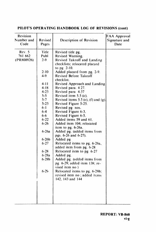
Rev. 5 Title Revised title pg.761 662 Publ Revised Warning.
(PR800926) 2-9 Revised Takeoff and Landingchecklists; relocated placardto pg 2-10.
2-10 Added placard from pg. 2-9.4-9 Revised Before Takeoff
checklist.4-1I Revised Approach and Landing4-18 Revised para. 4 27.4-23 Revised para 4.375-5 Revised item 5.5 (c).5-7 Revised items 5.5 (e), (f) and (gt5-23 Revised Figure 5-25.6-1 Revised pg nos.6-4 Revised Figure 6-3.6-6 Revised Figure 6-5.6-22 Added items 59 and 61.6-26 Added item 104; relocated
item to pg. 6-26a.6-26a Added pg. (added items from
pgs. 6-26 and 6-27).6-26b Added pg6-27 Relocated items to pg. 6-26a,
added item from pg. 6-286-28 Relocated item to pg 6-276-28a Added pg.6-28b Added pg. (added items from
pg 6-29: added item 138; re-vised item no )
6-29 Relocated items to pg. 6-28b:revised item no ; added items142, 143 and 144
REPORT: VB-860vi-g
PILOT'S OPERATING HANDBOOK LOG OF REVISIONS (cont)
Revision FAA ApprovalNumber and Revised Description of Revision Signature and
Code Pages Date
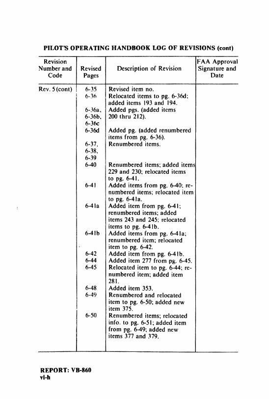
Rev. 5 (cont) 6-35 Revised item no.6-36 Relocated items to pg. 6-36d:
added items 193 and 194.6-36a, Added pgs. (added items6-36b, 200 thru 2\2).6-36c6-36d Added pg. (added renumbered
items from pg. 6-36).6-37, Renumbered items.6-38,6-396-40 Renumbered items; added items
229 and 230; relocated itemsto pg. 6-4 I.
6-4i Added items from pg. 6-40; re-numbered items; relocated itemto pg. 6-41a.
6-41a Added item from pg. 6-41;renumbered items; addeditems 243 and 245; relocateditems to pg. 6-4lb.
6-41b Added items from pg. 6-41a;renumbered item; relocateditem to pg. 6-42.
6-42 Added item from pg. 6-4lb.6-44 Added item 277 from pg. 6-45.6-45 Relocated item to pg. 6-44; re-
numbered item; added item281.
6-48 Added item 353.6-49 Renumbered and relocated
item to pg. 6-50; added newitem 375.
6-50 Renumbered items; relocatedinfo. to pg. 6-51; added itemfrom pg. 6-49; added newitems 377 and 379.
REPORT: VB-860vi-h
PILOT'S OPERATING HANDBOOK LOG OF REVISIONS (cont)
Revision FAA ApprovalNumber and Revised Description of Revision Signature and
Code Pages Date
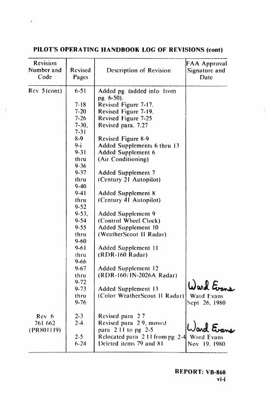
Rev 5(cont) 6-51 Added pg (added info frompg 6-50).
7-18 Revised Figure 7-17.7-20 Revised Figure 7-19.7-26 Revised Figure 7-257-30, Revised para. 7.277-318-9 Revised Figure 8-99-i Added Supplements 6 thru 139-31 Added Supplement 6thru (Air Conditioning)9-369-37 Added Supplement 7thru (Century 21 Autopilot)9-409-41 Added Supplement 8thru (Century 41 Autopilot)9-529-53, Added Supplement 99-54 (Control Wheel Clock)9-55 Added Supplement 10thru (WeatherScout II Radar)9-609-61 Added Supplement 11thru (RDR-I60 Radar)9-669-67 Added Supplement 12thru (RDR-160/IN-2026A Radar)
Added Supplement 13thru (Color WeatherScout ll Radar) Wald Evans9-76 Sept 26, 1980
Rev 6 2-3 Revised para 2 7761 662 2-4 Revised para 2 9, moved
(PR801I19) para 2II topg 2-5 OA2-5 Relocated para 2 I I from pg 2-4 Ward Evans6-24 Deleted items 79 and 81 Nov 19, 1980
REPORT: VB-860vi-i
PILOT'S OPERATING HANDBOOK LOG OF REVISIONS (cont)
Revision FAA ApprovalNumber and Revised Description of Revision Signature and
Codes Pages Date
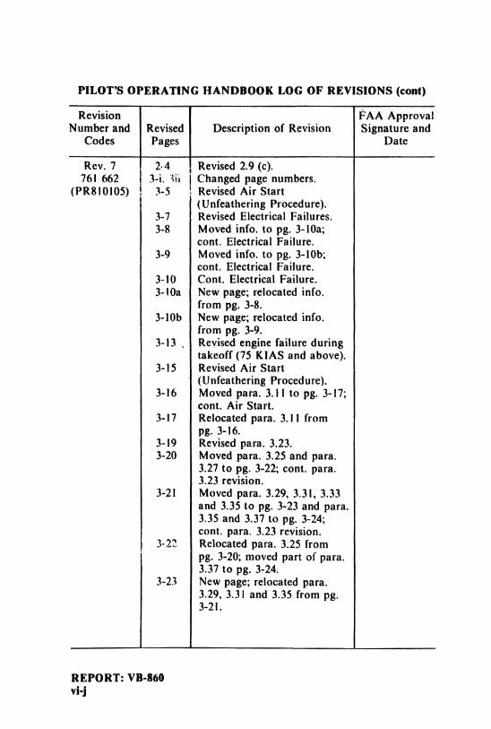
Rev. 7 2.4 Revised 2.9 (c).761 662 3-i. 3ü Changed page numbers.
(PR810105) 3-5 Revised Air Start(Unfeathering Procedure).
3-7 Revised Electrical Failures.3-8 Moved info. to pg. 3-10a;
cont. Electrical Failure.3-9 Moved info. to pg. 3-10b;
cont. Electrical Failure.3-10 Cont. Electrical Failure.3-10a New page; relocated info.
from pg. 3-8.3-10b New page; relocated info.
from pg. 3-9.3-13 , Revised engine failure during
takeoff (75 KIAS and above).3-15 Revised Air Start
(Unfeathering Procedure).3-16 Moved para. 3.11 to pg. 3-17;
cont. Air Start.3-17 Relocated para. 3.1 I from
pg. 3-16.3-19 Revised para. 3.23.3-20 Moved para. 3.25 and para.
3.27 to pg. 3-22; cont. para.3.23 revision.
3-21 Moved para. 3.29, 3.31, 3.33and 3.35 to pg. 3-23 and para.3.35 and 3.37 to pg. 3-24;cont. para. 3.23 revision.
3-22 Relocated para. 3.25 frompg. 3-20; moved part of para.3.37 to pg. 3-24.
3-23 New page; relocated para.3.29, 3.31 and 3.35 from pg.3-21.
REPORT: VB-860vi-j
PILOT'S OPERATING HANDBOOK LOG OF ÁEVISIOÑS (cont)
Revision FAA ApprovalNumber and Revised Description of Revision Signature and
Codes Pages Date
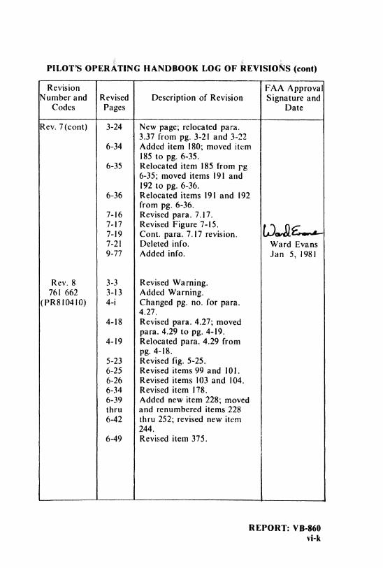
Rev.7(cont) 3-24 New page; relocated para.3.37 from pg. 3-21 and 3-22
6-34 Added item 180; moved item185 to pg. 6-35.
6-35 Relocated item 185 from pg6-35; moved items 191 and192 to pg. 6-36.
6-36 Relocated items 191 and 192from pg. 6-36.
7-16 Revised para. 7.17.7-17 Revised Figure 7-15.7-19 Cont. para. 7.17 revision.7-21 Deleted info. Ward Evans9-77 Added info. Jan 5, 198I
Rev. 8 3-3 Revised Warning.761 662 3-13 Added Warning.
(PR810410) 4-i Changed pg. no. for para.4.27.
4-18 Revised para. 4.27; movedpara. 4.29 to pg. 4-19.
4-19 Relocated para. 4.29 frompg. 4-18.
5-23 Revised fig. 5-25.6-25 Revised items 99 and 101.6-26 Revised items 103 and 104.6-34 Revised item 178.6-39 Added new item 228; movedthru and renumbered items 2286-42 thru 252; revised new item
244.6-49 Revised item 375.
REPORT: VB-860vi-k
PILOT'S OPERATING HANDBOOK LOG OF REVISIONS (cont)
Revision FAo4 ApprovalNumber and Revised Description of Revision Signature and
Codes Pages Date
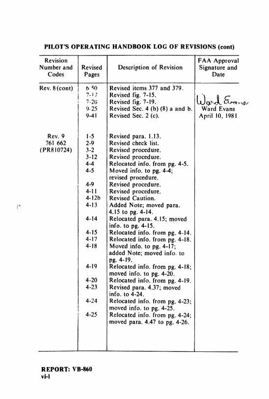
Rev.8(cont) 6 50 Revised items377 and 379,737 Revised fig.7-15.7-20 Revised fig. 7-19- 0074 t·*. a9-25 Revised Sec.4 (b)(8)a and b. VVard Evans9-41 Revised Sec. 2 (c). April 10, 198I
Rev.9 1-5 Revised para.1.13.761 662 2-9 Revised check list.
(PR810724) 3-2 Revised procedure.3-12 Revised procedure.4-4 Relocated info. frorn pg;.4-5.4-5 Afoved info.to pg.4-4;
revised procedure.4-9 Revised procedure.4-11 Revised procedure.4-12b Revised Caution.4-13 Added Note; moved para.
4.15 to pg.4-14.4-14 Relocated para.4.15; nioved
info.to pg.4-15.4-15 Relocated info.frona pg.4-14.4-17 Relocated info.frona pg.4-18.4-18 Afoved info.to pg.4-17;
added Note; nioved info.topg.4-19.
4-19 Relocated info. frona pg.4-18;naoved info.to pg.4-20.
4-20 Relocated info. frona pg.4-19.4-23 Revised para. 4.37; moved
info.to 4-24.4-24 Relocated info. from pg. 4-23;
nioved info.to pg.4-25.4-25 Relocated info. frona pg.4-24;
nioved para.4.47 to pg.4-26.
REPORT: VB-860vi-I
PILOT'S OPERATING HANDBOOK LOG OF REVISIONS (cont)
Revision FAA ApprovalNumber and Revised Description of Revision Signature and
Codes Pages Date
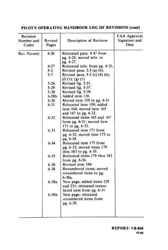
Rev.9(cont) 4-26 Relocated para. 4.47 frompg. 4-25; moved info topg. 4-27.
4-27 Relocated info. from pg. 4-26.5-3 Revised para. 5.5 (a) (6).5-7 Revised para. 5.5 (e) (4) (6);
(f) (1); (g) (1)5-26 Revised fig. 5-31.5-29 Revised fig. 5-37.5-30 Revised fig. 5-39.6-28b Added item 136.6-30 Moved item 159 to pg. 6-316-31 Relocated item 159; added
item 164; moved item 165and 167 to pg. 6-32.
6-32 Relocated items 165 and 167from pg. 6-31; moved item171 to pg. 6-33.
6-33 Relocated item 17] frompg. 6-32; moved item 175 topg. 6-34.
6-34 Relocated item 175 frompg. 6-33; moved items 179thru 183 to pg. 6-35.
6-35 Relocated items 179 thru 183from pg. 6-34.
6-36 Revised item 194.6-38 Renumbered items; moved
renumbered items to pg.6-38a.
6-38a New page; added items 229and 231; relocated renum-bered item from pg. 6-38
6-38b New page; relocatedrenumbered items frompg. 6-39.
REPORT: VB-860vi-m
PILOT'S OPERATING HANDBOOK LOG OF REVISIONS (cont)
Revision FAA ApprovalNumber and Revised Description of Revision Signature and
Codes Pages [)ate
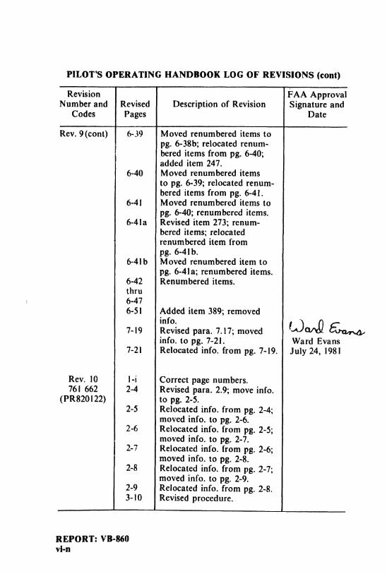
Rev.9(cont) 6-39 Moved renumbered items topg.6-38b; relocated renutn-bered itenas froni pg.6-40;added itena 247.
6-40 Afoved renunabered itenasto pg.6-39; relocated renoun-bered iterns froni pg.6-41.
6-41 Nioved renunabered itenis topg.6-40; renunibered itenas.
6-41a Revised itena 273;renuna-bered itents; relocatedrenunabered itern frompg.6-41b.
6-41b Moved renumbered item topg.6-41a;renuntbered itenis.
6-42 Renunebered itenas.thru6-476-51 Added itena 389;renaoved
7-19 R vised para. 7.17; movedinfo.to pg.7-21. YVard Evans
7-21 Relocated info.froni pg.7-19. July 24, 1981
Rev. 10 1-i Correct page nunabers.761 662 2-4 Revised para. 2.9; move info.
(PR820122) to pg.2-5.2-5 Relocated info.frona pg.2-4;
rnoved info.to pg.2-6.2-6 Relocated info. from pg. 2-5;
nioved info.to pg.2-7.2-7 Relocated info. from pg. 2-6;
nioved info.to pg.2-8.2-8 Relocated info. frona pg.2-7;
nioved info.to pg.2-9.2-9 Refocated info. froni pg.2-8.3-10 Revised procedure.
REPORT: VB-860vi-n
PILOT'S OPERATING HANDBOOK LOG OF REVISIONS (cont)
Revision FAA ApprovalNumber and Revised Description of Revision Signature and
Code Pages Date
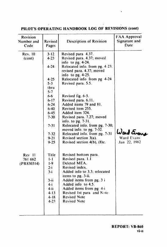
Rev. 10 3-12 Revised para 4.37.(cont) 4-23 Revised para. 4.37; moved
info to pg. 4-24.4-24 Relocated info. from pg. 4-23;
revised para. 4.37; movedinfo to pg. 4-25.
4-25 Relocated info from pg 4-245-3 Revised para. 5.5.thru5-76-6 Revised fig. 6-5.6-17 Revised para. 6.1I.6-24 Added items 79 and 81.6-40 Revised item 255.6-45 Added item 324.7-30 Revised para. 7.27; moved
info. to pg. 7-31.7-31 Relocated info. from pg. 7-30;
moved info. to pg. 7-32.7-32 Relocated info. from pg. 7-319-21 Revised section 3(a). Ward Euns9-25 Revised section 4(b), (8)c. Jan 22, 1982
Rev I1 Title Revised bottom para.761 662 1-1 Revised para. I.I
(PR830314) 1-9 Deleted MEA.2-i Revised index.3-i Added info to 3.3; relocated
items to pg. 3-ii.3-ii Added items from pg. 3 i4-i Added info to 4.5.4-ii Added items from pg 4-i4-13 Revised ist para and Note4-18 Revised Note4-23 Revised Note
REPORT: VB-860vi-o
PILOT'S O ERATINC HANDBOOK LOG OF REVI JIONS (cont)kevision LAAApproval
Number and Revised Descriptionof Revisions SignatureCode Pages and Date
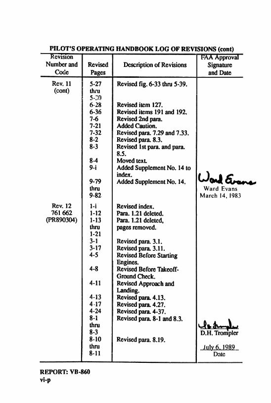
Rev. 11 5-27 Revisedfig. 6-33 thru 5-39.(cont) thru
5-306-28 Revised item 127.6-36 Revised items 191and 192.7-6 Revised2nd para.7-21 AddedCaution.7-32 Revised para. 7.29and 7.33.8-2 Revised para. 8.3.8-3 Revised 1stpara. and para.
8.5.8-4 Moved text.9-i Added SupplementNo. 14to
9-79Add
SupplementNo. 14.thru Ward Evans9-82 March 14, 1983
Rev. 12 1-i Revised index.761 662 1-12 Para. 1.21deleted.
(PR890304) 1-13 Para. 1.21deleted,thru pages removed.1-213-1 Revisedpara. 3.1.3-17 Revisedpara. 3.11.4-5 RevisedBefore Starting
Engines.4-8 RevisedBeforeTakeoff-
GroundCheck.4-11 RevisedApproachand
Landing.4-13 Revisedpara. 4.13.4
-17
Revisedpara. 4.27.4-24 Revised para. 4-37.8-1 Revisedpara. 8-1 and 8.3.thru da8-3 D.H. Trompler8-10 Revisedpara. 8.19.thru Julv 6, 19898-11 Date
REPORT: VB-860vi-p
TABLE OF CONTENTS
SECTION 1 GENERAL
SECTION 2 LIMITATIONS
SECTION 3 EMERGENCY PROCEDURES
SECTION 4 NORMAL PROCEDURES
SECTION 5 PERFORMANCE
SECTION 6 WEIGHT AND BALANCE
SECTION 7 DESCRIPTION AND OPERATION OFTHE AIRPLANE AND ITS SYSTEMS
SECTION 8 AIRPLANE HANDLING, SERVICINGAND MAINTENANCE
SECTION 9 SUPPLEMENTS
SECTION 10 SAFETY TIPS
REPORT: VB-860vii

TABLE OF CONTENTS
SECTION I
GENERAL
Paragraph PageNo No
1 1 Introduction ........................ ............. 1-1I 3 Engine .............. .. ... .... ............ l-31 5 Propeller ................. . ....... . ........... I-3I 7 Fuel .......................... .................. I-41.9 Oil............................. .... ............ 1-41 11 Maximum Weights ................ ............ 1-41.13 Standard Airplane Weights ......................... I-51.15 Baggage Space .................................... 1-51 17 Specific Loadings..................... . .......... 1-51.19 Symbols, Abbreviations and Terminology . . . . . . . . . . . . . I-6
I
REPORT: VB-860I-i

PIPER AIRCRAFT CORPORATION SECTION IPA-44-180, SEMINOLE GENER AL
SECTION I
GENER AL
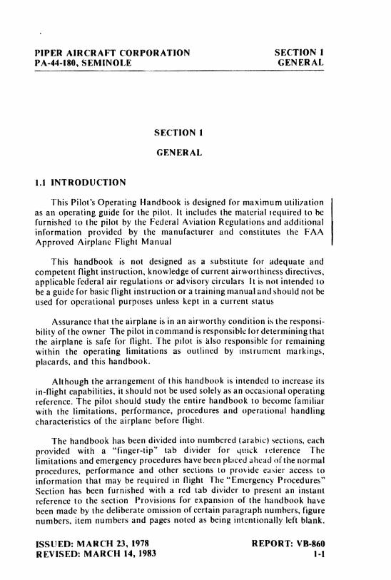
1.1 INTRODUCTION
This Pilot's Operating Handbook is designed for maximum utili7ation
as an operating guide for the pilot. It includes the material required to befurnished to the pilot by the Federal Aviation Regulations and additionalinformation provided by the manufactures and constitutes the FAAApproved Airplane Flight Manual
This handbook is not designed as a substitute for adequate andcompetent flight instruction, knowledge of current airworthiness directives,applicable federal air regulations or advisory circulars It is not intended tobe a guide for basic flight instruction or a training manual and should not beused for operational purposes unless kept in a current status
Assurance that the airplane is in an airworthy condition is the responsi-bility of the owner The pilot in command is responsible for determining thatthe airplane is safe for flight. The pilot is also responsible for remainingwithin the operating limitations as outlined by instrument markings,placards, and this handbook.
Although the arrangement of this handbook is intended to increase itsin-flight capabilities, it should not be used solely as an occasional operatingreference. The pilot should study the entire handbook to become familiarwith the limitations, performance, procedures and operational handlingcharacteristics of the airplane before flight.
The handbook has been divided into numbered (arabic) sections, eachprovided with a "finger-tip" tab divider for quick reference Thelimitations and emergency procedures have been placed ahead of the normalprocedures, performance and other sections to provide easier access toinformation that may be required in flight The "Emergency Procedures"Section has been furnished with a red tab divider to present an instantreference to the section Provisions for expansion of the handbook havebeen made by the deliberate omission of certain paragraph numbers, figurenumbers, item numbers and pages noted as being intentionally left blank.
ISSUED: MARCH 23, 1978 REPORT: VB-860REVISED: MARCH 14, 1983 g.g
SECTION 1 PIPER AIRCRAFT CORPORATIONGENERAL PA-44-180, SEMINOLE
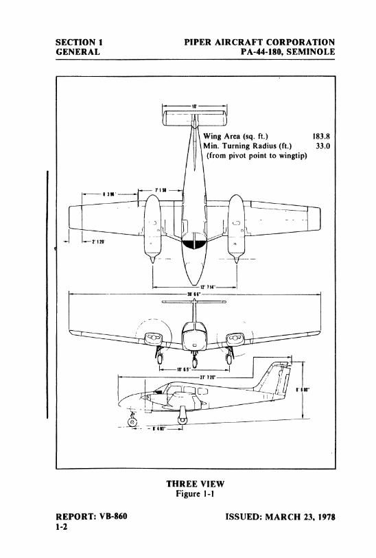
Wing Area (sg. ft.) 183.8Min. Turning Radius (ft.) 33.0(from pivot point to wingtip)
f 126
17 714"35 66"
THREE VIEWFigure I-I
REPORT: VB-860 ISSUED: MARCH 23, 19781-1
PIPER AIRCRAFT CORPORATION SECTION 1PA-44-180, SEMINOLE GENERAL
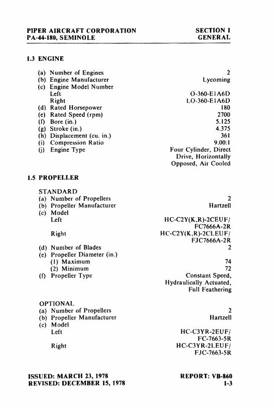
1.3 ENGINE
(a) Number of Engines 2(b) Engine Manufacturer Lycoming(c) Engine Model Number
Left O-360-E1A6DRight LO-360-ElA6D
(d) Rated Horsepower 180(e) Rated Speed (rpm) 2700(f) Bore (in.) 5.125(g) Stroke (in.) 4.375(h) Displacement (cu. in.) 361(i) Compression Ratio 9.00:1(j) Engine Type Four Cylinder, Direct
Drive, HorizontallyOpposed, Air Cooled
1.5 PROPELLER
STANDARD(a) Number of Propellers 2(b) Propeller Manufacturer Rartzell(c) Model
Left HC-C2Y(K,R)-2CEUF|FC7666A-2R
Right H C-C2Y(K,R)-2CLEU F/FJC7666A-2R
(d) Number of Blades 2(e) Propeller Diameter (in.)
(1) Maximum 74(2) Minimum 72
(f) Propeller Type Constant Speed,Hydraulically Actuated,
Full Feathering
OPTIONAL(a) Number of Propellers 2(b) Propeller Manufacturer Hartzell(c) Model
Left HC-C3YR-2EUF/FC-7663-5R
Right HC-C3YR-2LEUF/FJC-7663-5R
ISSUED: MARCH 23, 1978 REPORT: VB-860REVISED: DECEMBER 15, 1978 1.3
SECTION 1 PIPER AIRCRAFT CORPORATIONGENERAL PA-44-180, SEMINOLE
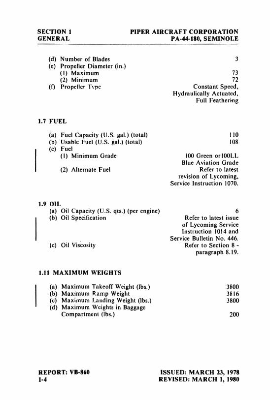
(d) Number of Blades 3(e) Propeller Diameter (in.)
(1) Maximum 73(2) Minimum 72
(f) Propeller Tvpe Constant Speed,Hydraulically Actuated,
Full Feathering
1.7 FUEL
(a) Fuel Capacity (U.S. gal.) (total) I 10(b) Usable Fuel (U.S. gal.) (total) 108(c) Fuel
(I) Minimum Grade 100 Green or100LLBlue Aviation Grade
(2) Alternate Fuel Refer to latestrevision of Lycoming,
Service Instruction 1070.
L9 OIL(a) Oil Capacity (U.S. qts.) (per engine) 6(b) Oil Specification Refer to latest issue
of Lycoming ServiceInstruction 1014 and
Service Bulletin No. 446.(c) Oil Viscosity Refer to Section 8 -
paragraph 8.19.
1.11 MAXIMUM WEIGHTS
(a) Maximum Takeoff Weight (lbs.) 3800(b) Maximum Ramp Weight 3816(c) Maximum Landing Weight (Ibs.) 3800(d) Maximum Weights in Baggage
Compartment (lbs.) 200
REPORT: VB-860 ISSUED: MARCH 23, 19781-4 REVISED: MARCH I, 1980
PIPER AIRCRAFT CORPORATION SECTION IPA-44-180, SEMINOLE GENERAL
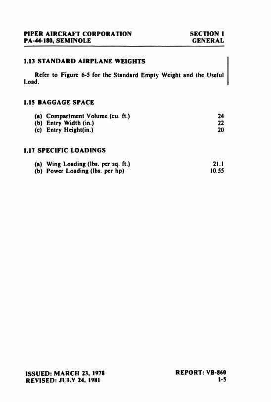
1.13 STANDARD AIRPLANE WEIGHTS
Refer to Figure 6-5 for the Standard Empty Weight and the UsefulLoad.
1.15 BAGGAGE SPACE
(a) Compartment Volume (cu.ft.) 24(b) Entry Width (in.) 22(c) Entry Height(in.) 20
1.17 SPECIFIC LOADINGS
(a) Wing Loading (lbs.per sg. ft.) 21.1(b) Power Loading (ibs. per hp) 10.55
ISSUED: MARCH 23, 1978 REPORT: VB•860REVISED: JULY 24, 1981 1-5
SECTION 1 PIPER AIRCRAFT CORPORATIONGENERAL PA-44-180, SEMINOLE
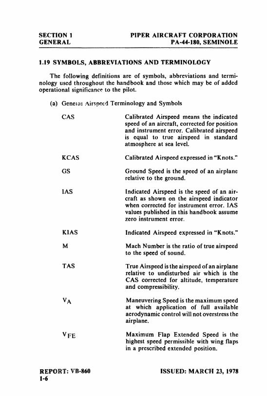
1.19 SYMBOLS, ABBREVIATIONS AND TERMINOLOGY
The following definitions are of symbols, abbreviations and termi-nology used throughout the handbook and those which may be of addedoperational significance to the pilot.
(a) Geneial Airspeed Terminology and Symbols
CAS Calibrated Airspeed means the indicatedspeed of an aircraft, corrected for positionand instrument error. Calibrated airspeedis equal to true airspeed in standardatmosphere at sea level.
KCAS Calibrated Airspeed expressed in "Knots."
GS Ground Speed is the speed of an airplanerelative to the ground.
IAS Indicated Airspeed is the speed of an air-craft as shown on the airspeed indicatorwhen corrected for instrument error. IASvalues published in this handbook assumezero instrument error.
KIAS Indicated Airspeed expressed in "Knots."
M Mach Number is the ratio of true airspeedto the speed of sound.
TAS True Airspeed is the airspeed of an airplanerelative to undisturbed air which is theCAS corrected for altitude, temperatureand compressibility.
VA Maneuvering Speed is the maximum speedat which application of full availableaerodynamic control will not overstress theairplane.
V FE Maximum Flap Extended Speed is thehighest speed permissible with wing flapsin a prescribed extended position.
REPORT: VB-860 ISSUED: MARCH 23, 19781-6
PIPER AIRCRAFT CORPORATION SECTION IPA-44-180, SEMINOLE GENERAL
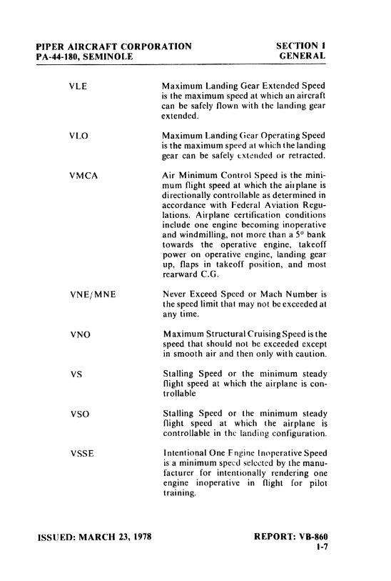
VLE Maximum Landing Gear Extended Speedis the maximum speed at which an aircraft
can be safely flown with the landing gearextended.
VLO Maximum Landing Gear Operating Speedis the maximum speed at which the landinggear can be safely extended or retracted.
VMCA Air Minimum Control Speed is the mini-
mum flight speed at which the air plane isdirectionally controllable as determined inaccordance with Federal Aviation Regu-lations. Airplane certification conditionsinclude one engine becoming inoperativeand windmilling, not more than a 5° banktowards the operative engine, takeoffpower on operative engine, landing gearup, flaps in takeoff position, and mostrearward C.G.
VNE/MNE Never Exceed Speed or Mach Number isthe speed limit that may not be exceeded atany time.
VNO Maximum Structural Cruising Speed is thespeed that should not be exceeded exceptin smooth air and then only with caution.
VS Stalling Speed or the minimum steadyflight speed at which the airplane is con-trollable
VSO Stalling Speed or the minimum steadyflight speed at which the airplane iscontrollable in the landing configuration.
VSSE Intentiona1One Engine Inoperative Speedis a minimum speed selected by the manu-facturer for intentionally rendering oneengine inoperative in flight for pilottraining.
ISSUED: MARCH 23, 1978 REPORT: VB-8601-7
SECTION I PIPER AIRCRAFT CORPORATIONGENERAL PA-44-180, SEMINOLE
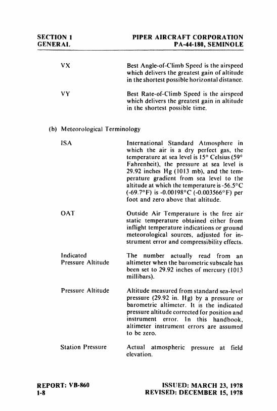
VX Best Angle-of-Climb Speed is the airspeedwhich delivers the greatest gain of altitudein the shortest possible horizontal distance.
VY Best Rate-of-Climb Speed is the airspeedwhich delivers the greatest gain in altitudein the shortest possible time.
(b) Meteorological Terminology
ISA International Standard Atmosphere inwhich the air is a dry perfect gas, thetemperature at sea level is 15° Celsius (59°Fahrenheit), the pressure at sea level is29.92 inches Hg (1013 mb), and the tem-perature gradient from sea level to thealtitude at which the temperature is -56.5°C(-69.7°F) is -0.00198°C (-0.003566°F) perfoot and zero above that altitude.
OAT Outside Air Temperature is the free airstatic temperature obtained either frominflight temperature indications or groundmeteorological sources, adjusted for in-strument error and compressibility effects.
Indicated The number actually read from anPressure Altitude attimeter when the barometric subscale has
been set to 29.92 inches of mercury (1013millibars).
Pressure Altitude Altitude measured from standard sea-levelpressure (29.92 in. Hg) by a pressure orbarometric altimeter. It is the indicatedpressure altitude corrected for position andinstrument error. In this handbook,altimeter instrument errors are assumedto be zero.
Station Pressure Actual atmospheric pressure at fieldelevation.
REPORT: VB-860 ISSUED: MARCH 23, 19781-8 REVISED: DECEMBER 15, 1978
PIPER AIRCRAFT CORPORATION SECTION 1PA-44-180, SEMINOLE GENERAL
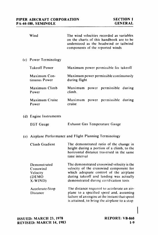
Wind The wind velocities recorded as variables
on the charts of this handbook are to beunderstood as the headwind or tailwindcomponents of the reported winds
(c) Power Terminology
Takeoff Power Maximum power permissible for takeoff
Maximum Con- Maximum power permissible continuouslytinuous Power during flight
Maximum Climb Maximum power permissible duringPower climb.
Maximum Cruise Maximum power permissible duringPower cruise
(d) Engine instruments
EGT Gauge Exhaust Gas Temperature Gauge
(e) Airplane Performance and Flight Planning Terminology
Climb Gradient The demonstrated ratio of the change inheight during a portion of a climb, to thehorizontal distance traversed in the sametime interval
Demonstrated The demonstrated crosswind velocity is theCrosswind velocity of the crosswind component forVelocity which adequate control of the airplane(DEMO during takeoff and landing was actuallyX-WIND) demonstrated durmg cenification tests
Accelerate-Stop The distance required to accelerate an air-Distance plane to a specified speed and, assuming
failure of an engine at the instant that speedis attained, to bring the airplane to a stop
ISSUED: MARCH 23, 1978 REPORT: VB-860REVISED: MARCH 14, 1983 ¡.9
SECTION 1 PIPER AIRCRAFT CORPORATIONGENERAL PA-44-180, SEMINOLE
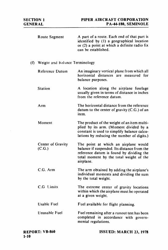
Route Segment A part of a route. Each end of that part isidentified by (1) a geographical locationor (2) a point at which a definite radio fixcan be established.
(f) Weight and Balance Terminology
Reference Datum An imaginary vertical plane from which allhorizontal distances are measured forbalance purposes.
Station A location along the airplane fuselageusually given in terms of distance in inchesfrom the reference datum.
Arm The horizontal distance from the referencedatum to the center of gravity (C.G.) of anitem.
Moment The product of the weight ofan item multi-plied by its arm. (Moment divided by aconstant is used to simplify balance calcu-lations by reducing the number of digits.)
Center of Gravity The point at which an airplane would(C.G.) balance if suspended. Its distance from the
reference datum is found by dividing thetotal moment by the total weight of theairplane.
C.G. Arm The arm obtained by adding the airplane'sindividual moments and dividing the somby the total weight.
C.G Limits The extreme center of gravity locationswithin which the airplane must be operatedat a given weight.
Usable Fuel Fuel available for flight planning.
Unusable Fuel Fuel remaining after a runout test has beencompleted in accordance with govern-mental regulations.
REPORT: VB-860 ISSUED: MARCH 23, 19781-10
PIPER AIRCRAFT CORPORATION SECTION 1PA-44-180, SEMINOLE GENERAL
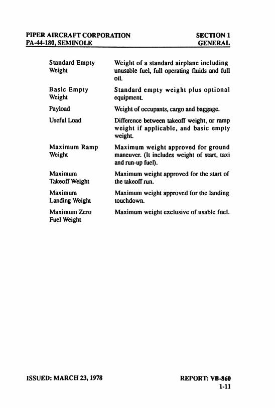
Standard Empty Weight of a standard airplane includingWeight unusable fuel, full operating fluids and full
oil.
Basic Empty Standard empty weight plus optionalWeight equipment.Payload Weightof occupants,cargo and baggage.Useful Load Differencebetween takeoff weight, or ramp
weight if applicable, and basic emptyweight.
Maximum Ramp Maximum weight approved for groundWeight maneuver. (It includes weight of start, taxi
and run-up fuel).Maximum Maximum weight approved for the start ofTakeoff Weight the takeoff run.
Maximum Maximum weight approved for the landingLanding Weight touchdown.Maximum Zero Maximum weight exclusive of usable fuel.Fuel Weight
ISSUED: MARCH 23, 1978 REPORT: VB-8601-11
SECTION 1 PIPER AIRCRAFT CORPORATIONGENERAL PA-44-180, SEMINOLE
THIS PAGE INTENTIONALLY LEFT BLANK
IREPORT: VB-860 ISSUED: MARCH 23, 19781-12 REVISED: MARCH 4, 1989
TABI E OF CONTENTS
SECTION 2
1 IMITATIONS
Paragraph PageNo No
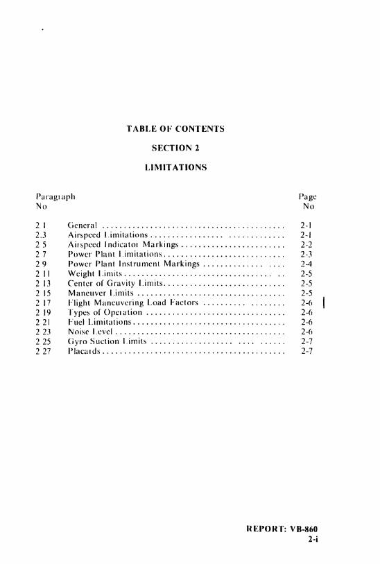
2 1 General ............. . .. . .......... 2-12.3 Airspeed Limitations.............. ......... 2-125 Airspeed Indicator Markings........................ 2-227 Power Plant Limitations............... .......... 2-329 Power Plant Instrument Markings .............. .... 242 Il Weight Limits.................. . ....... .. 2-52 13 Center of Gravity Limits.............. .......... 2-52 15 Maneuver Limits ................ ........... 2-52 17 Flight Maneuvering Load Factors .......... ........ 2-62 19 Types of Operation .............. . ........... 2-62 21 Fuel Limitations............. ......... 2-62 23 Noise Level............... . . ............ 2-62 25 Gyro Suction Limits .............. . . .... ...... 2-72 27 Placards.............. . . .. ........... 2-7
REPORT: VB-8602-i

PIPER AIRCRAFT CORPORATION SECTION 2PA-44-180, SEMINOLE LIMITATIONS
SECTION 2
LIMITATIONS
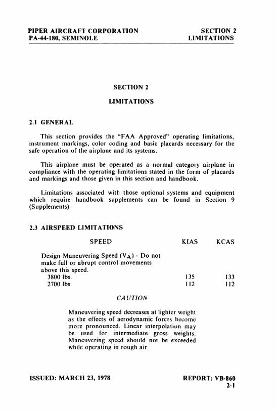
2.1 GENERAL
This section provides the "FAA Approved" operating limitations,instrument markings, color coding and basic placards necessary for thesafe operation of the airplane and its systems.
This airplane must be operated as a normal category airplane incompliance with the operating limitations stated in the form of placardsand markings and those given in this section and handbook.
Limitations associated with those optional systems and equipmentwhich require handbook supplements can be found in Section 9(Supplements).
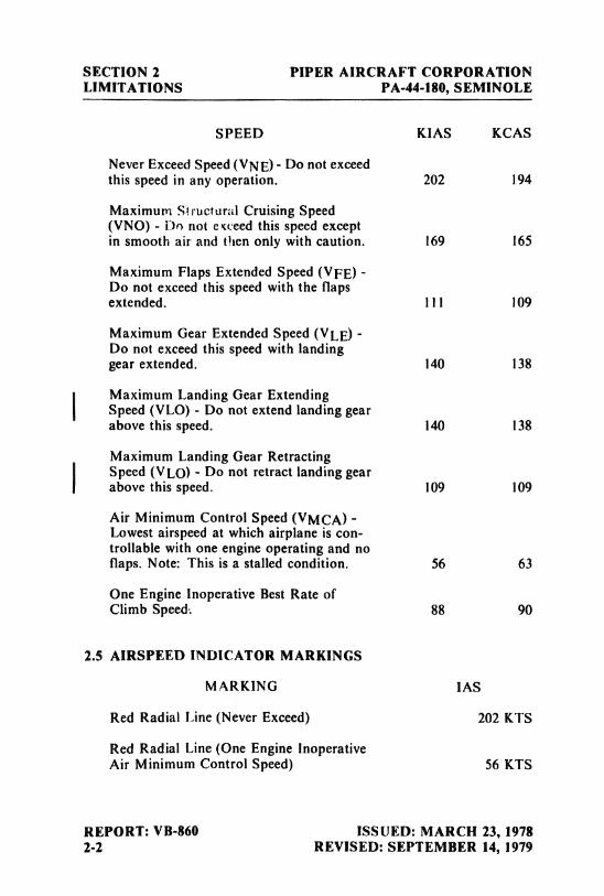
2.3 AIRSPEED LIMITATIONS
SPEED KIAS KCAS
Design Maneuvering Speed (VA) - Do notmake full or abrupt control movementsabove this speed.
3800 lbs. 135 1332700 lbs. I12 112
CAUTION
Maneuvering speed decreases at lighter weight
as the effects of aerodynamic forces becomemore pronounced. Linear interpolation maybe used for intermediate gross weights.Maneuvering speed should not be exceededwhile operating in rough air.
ISSUED: MARCH 23, 1978 REPORT: VB-8602-1
SECTION 2 PIPER AIRCRAFT CORPORATIONLIMITATIONS PA-44-180,SEMINOLE
SPEED KIAS KCAS
Never Exceed Speed (VNE) - Do not exceedthis speed in any operation. 202 194
Maximum Structural Cruising Speed(VNO) - Do not e weed this speed exceptin smooth air and then only with caution. 169 165
Maximum Flaps Extended Speed (VFE) -
Do not exceed this speed with the flapsextended. 111 109
Maximum Gear Extended Speed (VLE) -
Do not exceed this speed with landinggear extended. 140 138
IMaximum Landing Gear ExtendingSpeed (VLO) - Do not extend landing gearabove this speed. 140 138
Maximum Landing Gear Retracting
I Speed (VLO) - Do not retract landing gearabove this speed. 109 109
Air Minimum Control Speed (VMCA) -
Lowest airspeed at which airplane is con-trollable with one engine operating and noflaps. Note: This is a stalled condition. 56 63
One Engine Inoperative Best Rate ofClimb Speed. 88 90
2.5 AIRSPEED INDICATOR MARKINGS
MARKING IAS
Red Radial Line (Never Exceed) 202 KTS
Red Radial Line (One Engine InoperativeAir Minimum Control Speed) 56 KTS
REPORT: VB-860 ISSUED: MARCH 23, 19782-2 REVISED: SEPTEMBER 14, 1979
PIPER AIRCRAFT CORPORATION SECTION 2PA-44-180, SEMINOLE LIMITATIONS
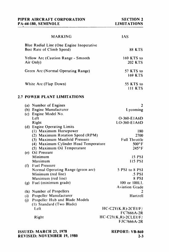
MARKING IAS
Blue Radial Line (One Engine inoperativeBest Rate of Climb Speed) 88 KTS
Yellow Arc (Caution Range - Smooth 169 KTS toAir Only) 202 KTS
Green Arc (Normal Operating Range) 57 KTS to169 KTS
White Arc (Flap Down) 55 KTS tolli KTS
2.7 POWER PLANT LIMITATIONS
(a) Number of Engines 2(b) Engine Manufacturer Lycoming(c) Engine Model No.
Left O-360-E IA6DRight LO-360-E lA6D
(d) Engine Operating Limits(1) Maximum Horsepower 180(2) Maximum Rotation Speed (RPM) 2700(3) Maximum Manifold Pressure Full Throttle(4) Maximum Cylinder Head Temperature 500°F(5) Maximum Oil Temperature 245°F
(e) Oil PressureMinimum 15 PSIMaximum 115 PSI
(f) Fuel PressureNormal Operating Range (greenarc) 5 PSI to 8 PSIMinimum (red line)
.5
PSIMaximum (red line) 8 PSI
(g) Fuel (minimum grade) 100 or 100LLAsiation Grade
(h) Number of Propellers 2(i) Propeller Manufacturer Hartzell(j) Propeller Hub and Blade Models
(I) Standard (Two Blade)Left HC-C2Y(K,R)-2CEUF/
FC7666A-2RRight HC-C2Y(K,R)-2CLEU F/
FJ C7666A-2R
ISSUED: MARCH 23, 1978 REPORT: VB-860REVISED: NOVEMBER 19, 1980 2-3
SECTION 2 PIPER AIRCRAFT CORPORATIONLIMITATIONS PA-44-180, SEMINOLE
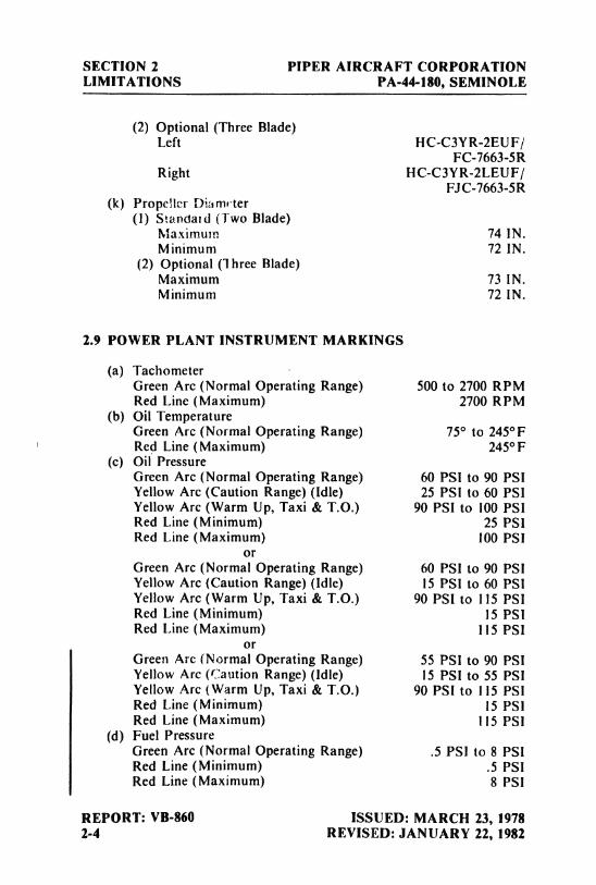
(2) Optional (Three Blade)Left HC-C3VR-2EUF/
FC-7663-5RRight HC-C3YR-2LEUF/
FJC-7663-5R(k) Propeller Dia meter
(1) Standard (Two Blade)Maximum 74 IN.Minimum 72 IN.
(2) Optional (Three Blade)Maximum 73 IN.Minimum 72 IN.
2.9 POWER PLANT INSTRUMENT MARKINGS
(a) TachometerGreen Arc (Normal Operating Range) 500 to 2700 RPMRed Line (Maximum) 2700 RPM
(b) Oil TemperatureGreen Arc (Normal Operating Range) 75° to 245°FRed Line (Maximum) 245°F
(c) Oil PressureGreen Arc (Normal Operating Range) 60 PSI to 90 PSIYellow Arc (Caution Range) (Idle) 25 PSI to 60 PSIYellow Arc (Warm Up, Taxi & T.O.) 90 PSI to 100 PSIRed Line (Minimum) 25 PSIRed Line (Maximum) 100 PSI
orGreen Arc (Normal Operating Range) 60 PSI to 90 PSIYellow Arc (Caution Range) (Idle) 15 PSI to 60 PSIYellow Arc (Warm Up, Taxi & T.O.) 90 PSI to 115 PSIRed Line (Minimum) 15 PSIRed Line (Maximum) 115 PSI
orGreen Arc (Normal Operating Range) 55 PSI to 90 PSIYellow Arc (Caution Range) (Idle) 15 PSI to 55 PSIYellow Arc (Warm Up, Taxi & T.O.) 90 PSI to I15 PSIRed Line (Minimum) 15 PSIRed Line (Maximum) 115 PSI
(d) Fuel PressureGreen Arc (Normal Operating Range) .5
PSI to 8 PSIRed Line (Minimum) .5
PSlRed Line (Maximum) 8 PSI
REPORT: VB-860 ISSUED: MARCH 23, 19782-4 REVISED: JANUARY 22, 1982
PIPER AIRCRAFT CORPORATION SECTION 2PA-44-180, SEMINOLE LIMITATIONS
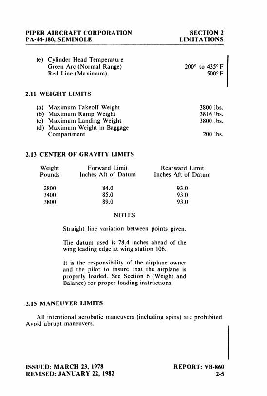
(e) Cylinder Head TemperatureGreen Arc (Normal Range) 200° to 435°FRed Line (Maximum) 500°F
2.11 WEIGHT LIMITS
(a) Maximum Takeoff Weight 3800 lbs.(b) Maximum Ramp Weight 3816 lbs.(c) Maximum Landing Weight 3800 lbs.(d) Maximum Weight in Baggage
Compartment 200 lbs.
2.13 CENTER OF GRAVITY LIMITS
Weight Forward Limit Rearward LimitPounds Inches Aft of Datum Inches Aft of Datum
2800 84.0 93.03400 85.0 93.03800 89.0 93.0
NOTES
Straight line variation between points given.
The datum used is 78.4 inches ahead of thewing leading edge at wing station 106.
It is the responsibility of the airplane ownerand the pilot to insure that the airplane isproperly loaded. See Section 6 (Weight andBalance) for proper loading instructions.
2.15 MANEUVER LIMITS
All intentional acrobatic maneuvers (includingspins) ale prohibited.Avoid abrupt maneuvers.
ISSUED: MARCH 23, 1978 REPORT: VB-860REVISED: JANUARY 22, 1982 2-5
SECTION 2 PIPER AIRCRAFT CORPORATIONLIMITATIONS PA-44-180, SEMINOLE
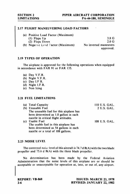
2.17 FLIGHT MANEUVERING LOAD FACTORS
(a) Positive Load Factor (Maximum)(1) Flaps Up 3.8 G(2) Flaps Down 2.0 G
(b) Negahve Load Factor (Maximum) No inverted maneuversapproved.
2.19 TYPES OF OPERATION
The airplane is approved for the following operations when equippedin accordance with FAR 91 or FAR 135.
(a) Day V.F.R.(b) Night V.F.R.(c) Day I.F R.(d) Night I.F.R.(e) Non Icing
2.21 FUEL LIMITATIONS
(a) Total Capacity I10 U.S. GAL.(b) Unusable Fuel 2 U.S. GAL.
The unusable fuel for this airplane hasbeen determined as 1.0 gallon in eachnacelle in critical flight attitudes.
(c) Usable Fuel 108 U.S. GAL.The usable fuel in this airplane hasbeen determined as 54 gallons in eachnacelle or a total of 108 gallons.
2.23 NOISE LEVEL
The corrected noise level of this aircraft is 74.7 d B(A) with the two bladepropeller and 75,6 d R(A) with the three blade propeller.
No determination has been made by the Federal AviationAdministration that the noise levels of this airplane are or should beacceptable or unacceptable for operation at, into, or out of, any airport.
REPORT: VB-860 ISSUED: MARCH 23, 19782-6 REVISED: JANUARY 22, 1982
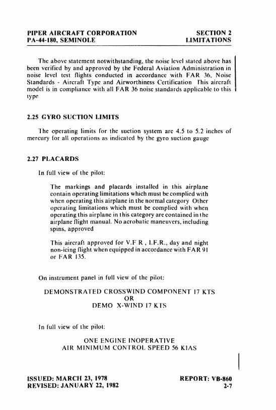
PIPER AIRCRAFT CORPORATION SECTION 2PA-44-180, SEMINOLE LIMITATIONS
The above statement notwithstanding, the noise level stated above hasbeen verified by and approved by the Federal Aviation Administration innoise level test flights conducted in accordance with FAR 36, NoiseStandards - Aircraft Type and Airworthiness Certification This aircraftmodel is in compliance with all FAR 36 noise standards applicable to thistype
2.25 GYRO SUCTION LIMITS
The operating limits for the suction system are 4.5 to 5.2 inches ofmercury for all operations as indicated by the gyro suction gauge
2.27 PLACARDS
In full view of the pilot:
The markings and placards installed in this airplanecontain operating limitations which must be complied withwhen operating this airplane in the normal category Otheroperating limitations which must be complied with whenoperating this airplane in this category are contained in theairplane flight manual. No acrobatic maneuvers, includingspins, approved
This aircraft approved for V.F R , l.F.R., day and nightnon-icing flight when equipped in accordance with FAR 91or FAR 135.
On instrument panel in full view of the pilot:
DEMONSTRATED CROSSWIND COMPONENT 17 KTSOR
DEMO X-WIND 17 KTS
In full view of the pilot:
ONE ENGINE INOPERATIVEAIR MlNIMUM CONTROL SPEED 56 KIAS
ISSUED: MARCH 23, 1978 REPORT: VB-860REVISED: JANUARY 22, 1982 2-7
SECTION 2 PIPER AIRCRAFT CORPORATIONLIMITATIONS PA-44-180, SEMINOLE
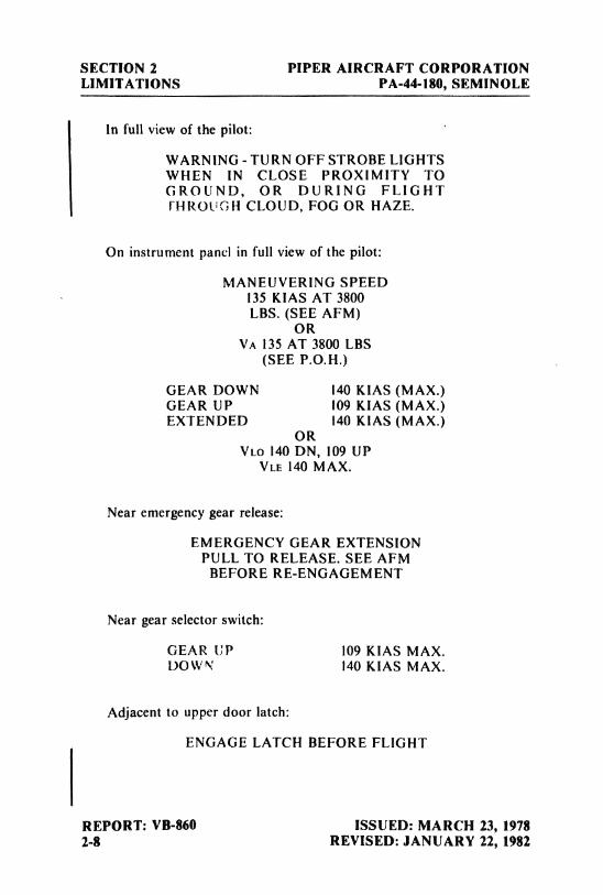
In full view of the pilot:
WARNING - TURN OFF STROBE LIGHTSWHEN IN CLOSE PROXIMITY TOGROUND, OR DURING FLIGHTfHROUGH CLOUD, FOG OR HAZE.
On instrument panel in full view of the pilot:
MANEUVERING SPEED135 KIAS AT 3800LBS. (SEE AFM)
ORVA 135 AT 3800 LBS
(SEE P.O.H.)
GEAR DOWN 140 KIAS (MAX.)GEAR UP 109 KIAS (MAX.)EXTENDED 140 KIAS (MAX.)
ORVLo 140 DN, 109 UP
VLE 140 MAX.
Near emergency gear release:
EMERGENCY GEAR EXTENSIONPULL TO RELEASE. SEE AFM
BEFORE RE-ENGAGEMENT
Near gear selector switch:
GEAR UP 109 KIAS MAX.DOWN 140 KIAS MAX.
Adjacent to upper door latch:
ENGAGE LATCH BEFORE FLIGHT
REPORT: VB-860 ISSUED: MARCH 23, 19782-8 REVISED: JANUARY 22, 1982
PIPER AIRCRAFT CORPORATION SECTION 2PA-44-180, SEMINOLE LIMITATIONS
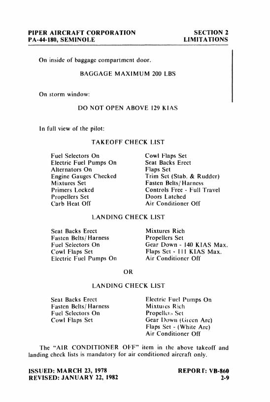
On inside of baggage compartment door.
BAGGAGE MAXIMUM 200 LBS
On storm window:
DO NOT OPEN ABOVE 129 KIAS
In full view of the pilot:
TAKEOFF CHECK LIST
Fuel Selectors On Cowl Flaps SetElectric Fuel Pumps On Seat Backs ErectAlternators On Flaps SetEngine Gauges Checked Trim Set (Stab. & Rudder)Mixtures Set Fasten Belts/ HarnessPrimers Locked Controls Free - Full TravelPropellers Set Doors LatchedCarb Heat Off Air Conditioner Off
LANDING CHECK LIST
Seat Backs Erect Mixtures RichFasten Belts/ Harness Propellers SetFuel Selectors On Gear Down - 140 KIAS Max.Cowl Flaps Set Flaps Set - 1II KIAS Max.Electric Fuel Pumps On Air Conditioner Off
OR
LANDING CHECK LIST
Seat Backs Erect Electric Fuel Pumps OnFasten Belts/ Harness Mixtuics RichFuel Selectors On Propello, SetCowl Flaps Set Gear Down (Green Arc)
Flaps Set - (White Arc)Air Conditioner Off
The "AIR CONDITIONER OFF" item in the above takeoff andlanding check lists is mandatory for air conditioned aircraft only.
ISSUED: MARCH 23, 1978 REPORI': VB-860REVISED: JANUARY 22, 1982 2-9
SECTION 2 PIPER AIRCRAFT CORPORATIONLIMITATIONS PA-44-180, SEMINOLE
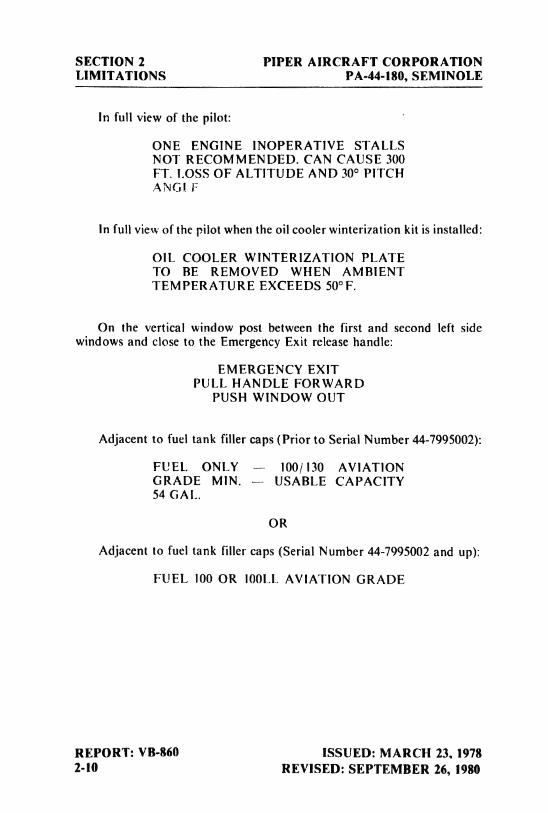
In full view of the pilot:
ONE ENGINE INOPERATIVE STALLSNOT RECOMMENDED. CAN CAUSE 300FT. LOSS OF ALT1TUDE AND 30° PITCHANGl F
ln full view of the pilot when the oil cooler winterization kit is installed:
OIL COOLER WINTERIZATION PLATETO BE REMOVED WHEN AMBlENTTEMPERATURE EXCEEDS 50°F.
On the vertical window post between the first and second left sidewindows and close to the Emergency Exit release handle:
EMERGENCY EXITPULL HANDLE FORWARD
PUSH WINDOW OUT
Adjacent to fuel tank filler caps (Prior to Serial Number 44-7995002):
FUEL ONLY - 100/130 AVIATIONGRADE MIN. -- USABLE CAPACITY54 GAL
OR
Adjacent to fuel tank filler caps (Serial Number 44-7995002 and up):
FUEL 100 OR 100LL AVIATION GRADE
REPORT: VB-860 ISSUED: MARCH 23, 19782-10 REVISED: SEPTEMBER 16, 1980
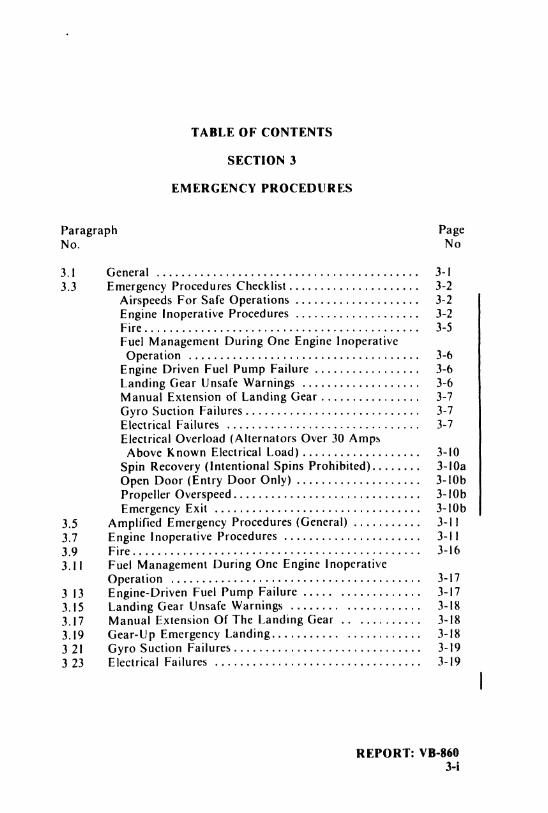
TABLE OF CONTENTS
SECTION 3
EMERGENCY PROCEDURES
Paragraph PageFLa. No
3.1 General ......................... . ........... 3-13.3 Ernergency Procedures Checklist..................... 3-2
Airspeeds For Safe Operations .................... 3-2Engine Inoperative Procedures .................... 3-2Fire................... .......... ............. 3-5Fuel Management During One Engine lnoperative
Operation ................ .................... 3-6Engine Driven Fuel Pump Failure ................. 3-6Landing Gear Unsafe VVarnings ................... 3-6Manual Extension of Landing Gear ................ 3-7Gyro Suction Failures............................ 3-7Electrical Failures ................ .............. 3-7Electrical Overload (Alternators Over 30 Amps
Above Known Electrical Load)................... 3-10Spin Recovery (Intentional Spins Prohibited). . . . . . . . 3-10aOpen Door (Entry Door Only) .................... 3-10bPropeller Overspeed............... . .......... 3-10bEmergency Exit ................................. 3-10b
3.5 Anaplified Ernergency Procedures (General) ........... 3-113.7 Engine Inoperative Procedures ...................... 3-Il3.9 Fire.............................. ............... 3-163.1I Fuel Management During One Engine Inoperative
Dperation ........................................ 3-173 13 Engine-Driven Fuel Pump Failure ..... ............. 3-173.15 Landing Gear Unsafe YVarnings ........ ............ 3-183.17 Manual Extension Of The Landing Gear .. .......... 3-183.19 Gear-Up Ernergency Landing........... ............ 3-183 21 Gyro Suction Failures-...--.......... . .......... 3-193 23 Electrical Failures ...-----............ ............ 3-19
I
REPORT: VB-8603-i
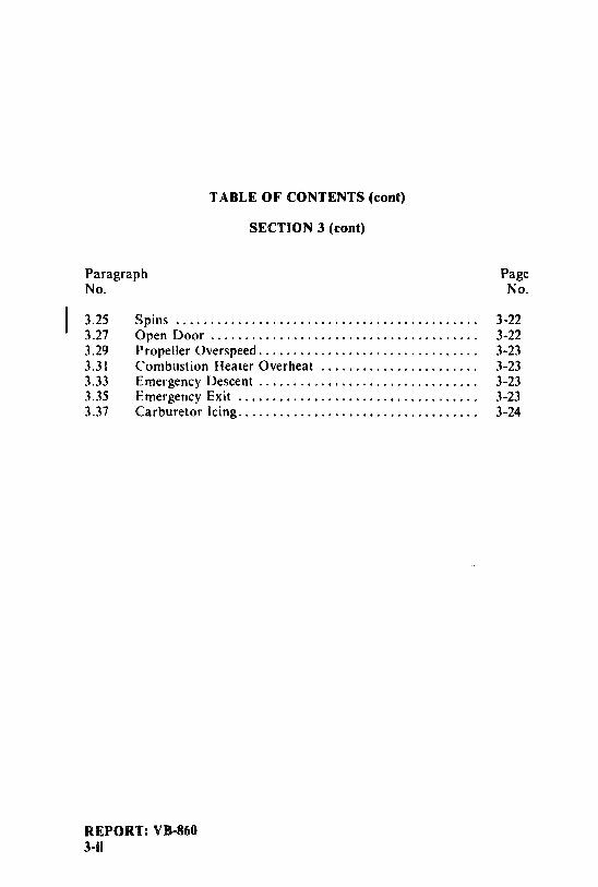
TABLE OF CONTENTS (cont)
SECTlON 3 (cont)
Paragraph PageNo. No.
3.25 Spins ............................................ 3-223.27 Open Door ....................................... 3-223.29 Propeller Overspeed................................ 3-233.31 Combustion Heater Overheat ....................... 3-233.33 Emergency Descent ................................ 3-233.35 Emergency Exit ................................... 3-233.37 Carburetor Icing................................... 3-24
REPORT: VB-8603-ii
PIPER AIRCRAFT CORPORATION SECTION 3PA-44-180, SEMINOLE EMERGENCY PROCEDURES
SECTION 3
EMERGENCY PROCEDURES
3.1 GENERAL
This section provides the recommended procedures for coping withvarious emergency or critical situations. All of the emergency proceduresrequired by the FAA as well as those necessary for operation of the airplane,as determined by the operating and design features of the airplane, arepresented.
Emergency procedures associated with optional systemsand equipment jwhich require handbook supplements are provided by Section 9, |Supplements.
This section is divided into two basic parts. The first part contains theemergency procedures checklists. These checklists supply an immediateaction sequence to be followed during critical situations with little emphasison the operation of the systems.
The second part of the section provides amplified emergency procedurescorresponding to the emergency procedures checklist items. These amplifiedemergency procedures contain additional information to provide the pilotwith a more complete description of the procedures so they may be moreeasily understood.
Pilots must familiarize themselves with the procedures given in thissection and must be prepared to take the appropriate action should anemergency situation arise. The procedures are offered as a course of actionfor coping with the particular situation or condition described. Theyare nota substitute for sound judgmentand common sense.
Most basic emergency procedures are a normal part of pilot training.The information presented in this section is not intended to replace thistraining. This information is intended to provide a source of reference for theprocedures which are applicable to this airplane. The pilot should reviewstandard emergency procedures periodically to remain proficient in them.
ISSUED: MARCH 23, 1978 REPORT: VB-860REVISED: MARCH 4, 1989 3-1
SECTION 3 PIPER AIRCRAFT CORPORATIONEMERGENCY PROCEDURES PA-44-180, SEMINOLE
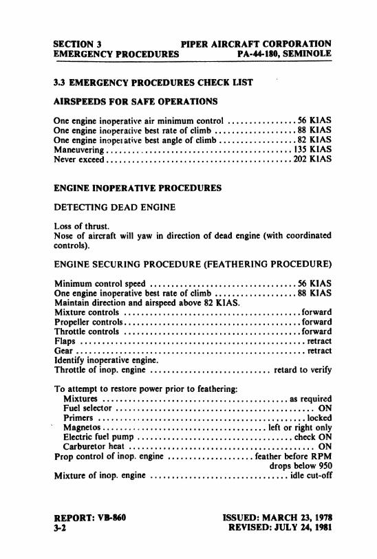
3.3 EMERGENCY PROCEDURES CHECK LIST
AIRSPEEDS FOR SAFE OPERATIONS
One engine inoperative air minimum control................56
KIASOne engine inoperative best rate of climb
...................88
KIASOne engine inoperative best angle of climb
..................82
KIASManeuvering........................................... 135 KIASNever exceed........................................... 202 KIAS
ENGINE INOPERATIVE PROCEDURES
DETECTING DEAD ENGINE
Loss of thrust.Nose of aircraft will yaw in direction of dead engine (with coordinatedcontrols).
ENGINE SECURING PROCEDURE (FEATHERING PROCEDURE)
Minimum control speed..................................56
KIASOne engine inoperative best rate of climb ...................88 KIASMaintain direction and airspeed above 82 KlAS.Mixture controls
.........................................forward
Propeller controls.........................................forwardThrottle controls
.........................................forward
Flaps .................................................... retractGear ..................................................... retractIdentify inoperative engine.Throttle of inop. engine ............................ retard to verify
To attempt to restore power prior to feathering:Mixtures ........................................... as requiredFuel selector .............................................. ONPrimers
................................................locked
Magnetos...................................... left or right onlyElectric fuel pump .................................... check ONCarburetor heat ........................................... ON
Prop control of inop. engine .................... feather before RPMdrops below 950
Mixture of inop. engine ................................ idle cut-off
REPORT: VB-860 ISSUED: MARCH 23, 19783-2 REVISED: JULY 24, 1981
PIPER AIRCRAFT CORPORATION SECTION 3PA-44-180, SEMINOLE EMERGENCY PROCEDURES
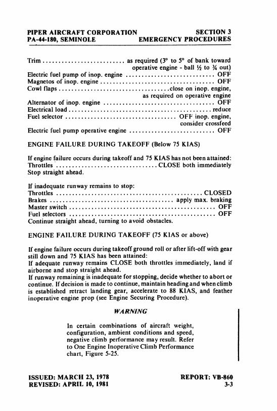
Trim.......................... as required (3° to 5° of bank towardoperative engine - ball ½ to ¾ out)
Electric fuel pump of inop. engine . . . . . . . . . . . . . . . . . . . . . . . . . . . . OFFMagnetos of inop. engine .................................... OFFCowl flaps...................................close on inop. engine,
as required on operative engineAlternator of inop. engine ................................... OFFElectricalload.............................................reduceFuel selector ................................... OFF inop. engine,
consider crossfeedElectric fuel pump operative engine ........................... OFF
ENGINE FAILURE DURING TAKEOFF (Below 75 KIAS)
If engine failure occurs during takeoff and 75 KIAS has not been attained:Throttles ................................CLOSE both immediatelyStop straight ahead.
If inadequate runway remains to stop:Throttles .............................................. CLOSEDBrakes ....................................... apply max. brakingMaster switch .............................................. OFFFuel selectors .............................................. OFFContinue straight ahead, turning to avoid obstacles.
ENGINE FAILURE DURING TAKEOFF (75 KIAS or above)
If engine failure occurs during takeoff ground roll or after lift-off with gearstill down and 75 KIAS has been attained:If adequate runway remains CLOSE both throttles immediately, land ifairborne and stop straight ahead.If runway remaining is inadequate for stopping, decide whether to abort orcontinue. If decision is made to continue, maintain heading and when climbis established retract landing gear, accelerate to 88 KIAS, and featherinoperative engine prop (see Engine Securing Procedure).
WARNING
In certain combinations of aircraft weight,configuration, ambient conditions and speed,negative climb performance may result. Referto One Engine Inoperative Climb Performancechart, Figure 5-25.
ISSUED: MARCH 23, 1978 REPORT: VB-860REVISED: APRIL 10, 1981 3-3
SECTION 3 PIPER AIRCRAFT CORPORATIONEMERGENCY PROCEDURES PA-44-180, SEMINOLE
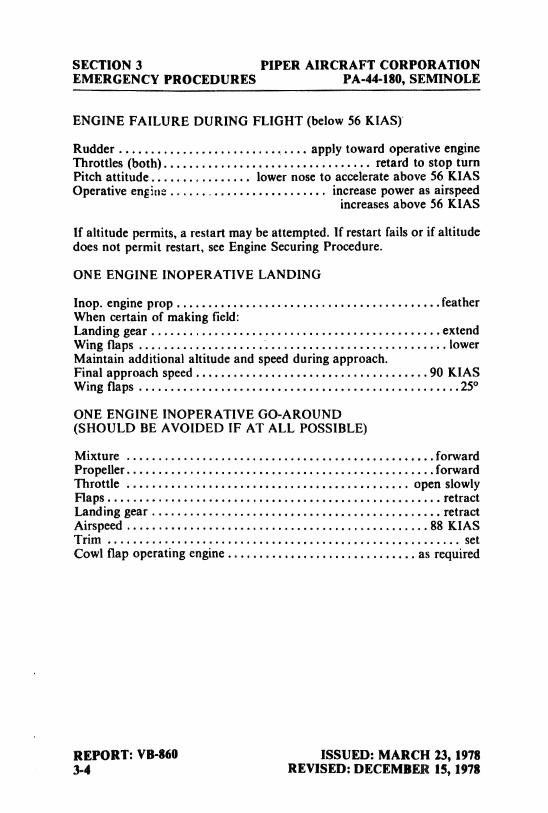
ENGINE FAILURE DURING FLIGHT (below56 KIAS)
Rudder .............................. apply toward operative engineThrottles (both)................................. retard to stop turnPitch attitude................ lower nose to accelerate above 56 KIASOperative engine ......................... increase power as airspeed
increases above 56 KIAS
If altitude permits, a restart may be attempted. If restart fails or if altitudedoes not permit restart, see Engine Securing Procedure.
ONE ENGINE INOPERATIVE LANDING
Inop. engine prop..........................................feather
When certain of making field:Landing gear ....... ..............
.........................extend
Wing flaps .... ............... .............................. lowerMaintain additional altitude and speed during approach.Final approach speed.....................................90 KIASWing flaps
...................................................25°
ONE ENGINE INOPERATIVE GO-AROUND(SHOULD BE AVOIDED IF AT ALL POSSIBLE)
Mixture.................................................forward
Propeller.................................................forwardThrottle ............................................. open slowlyFlaps..................................................... retractLanding gear .............................................. retractAirspeed
................................................88
KIASTrim ........................................................ setCowl flap operating engine .............................. as required
REPORT: VB-860 ISSUED: MARCH 23, 19783-4 REVISED: DECEMBER 15, 1978
PIPER AIRCRAFT CORPORATION SECTION 3PA-44-180, SEMINOLE EMERGENCY PROCEDURES
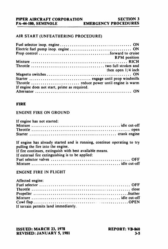
AIR START (UNFEATHERING PROCEDURE)
Fuel selector inop. engine..................................... ONElectric fuel pump inop. engine................................ ONProp control
.....................................forward
to cruiseRPM position
Mixture .................................................. RICHThrottle ...................................... two full strokes and
then open 1/4 inchMagneto switches............................................ ONStarter ................................ engage until prop windmillsThrottle ......................... reduce power until engine is warmIf engine does not start, prime as required.Alternator .................................................. ON
FIRE
ENGINE FIRE ON GROUND
If engine has not started:Mixture .............................................. idle cut-offThrottle ................................................... openStarter ............................................. crank engine
If engine has already started and is running, continue operating to trypulling the fire into the engine.If fire continues, extinguish with best available means.If external fire extinguishing is to be applied:Fuel selector valves ..............-.......................... OFFMixture .............................................. idle cut-off
ENGINE FIRE IN FLIGHT
Affected engine:Fuel selector ······ ·········-...···....................... OFFThtottle ................................................... closePropeller
.................................................feather
Mixture .............................................. idle cut-offCowl flap................................ ..............OPENIf terrain permits land immediately.
ISSUED: MARCH 23, 1978 REPORT: VB-860REVISED: JANUARY 5, 1981 3.5
SECTION 3 PIPER AIRCRAFT CORPORATIONEMERGENCY PROCEDURES PA-44-180, SEMINOLE
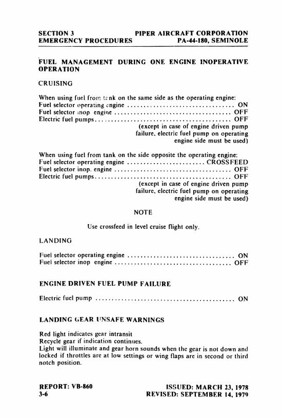
FUEL MANAGEMENT DURING ONE ENGINE INOPERATIVEOPERATION
CRUISlNG
When using fuel from ta nk on the same side as the operating engine:Fuel selector operating engine ................................. ONFuel selector mop engine .................................... OFFElectric fuel pumps.......................................... OFF
(except in case of engine driven pumpfailure, electric fuel pump on operating
engine side must be used)
When using fuel from tank on the side opposite the operating engine:Fuel selector operating engine ........................ CROSSFEEDFuel selector inop. engine .................................... OFFElectric fuel pumps.......................................... OFF
(except in case of engine driven pumpfailure, electric fuel pump on operating
engine side must be used)
NOTE
Use crossfeed in level cruise flight only.
LANDING
Fuel selector operating engine ................................. ONFuel selector inop engine .................................... OFF
ENGINE DRIVEN FUEL PUMP FAILURE
Electric fuel pumP ........................................... ON
LANDING GEAR UNSAFE WARNINGS
Red light indicates gear intransitRecycle gear if indication continues.Light will illuminate and gear horn sounds when the gear is not down andlocked if throttles are at low settings or wing flaps are in second or thirdnotch position.
REPORT: VB-860 ISSUED: MARCH 23, 19783-6 REVISED: SEPTEMBER 14, 1979
PIPER AIRCRAFT CORPORATION SECTION 3PA-44-180, SEMINOLE EMERGENCY PROCEDURES
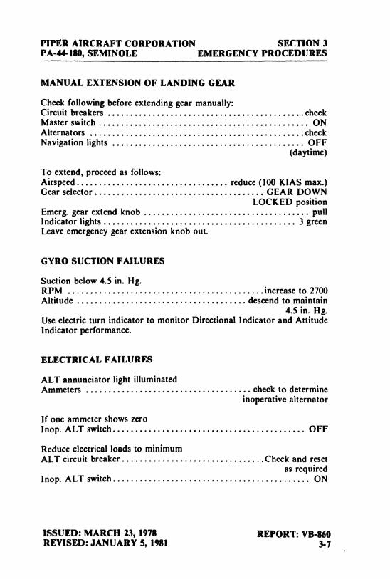
MANUAL EXTENSION OF LANDING GEAR
Check following before extending gear manually:Circuit breakers ............................................check
Master switch ............................................... ONAlternators
................................................check
Navigation lights ........................................... OFF(daytime)
To extend, proceed as follows:Airspeed.................................. reduce (100KIAS max.)Gear selector...................................... GEAR DOWN
LOCKED positionEmerg. gear extend knob ..................................... pullIndicator lights ........................................... 3 greenLeave emergency gear extension knob out.
GYRO SUCTION FAILURES
Suction below 4.5 in. Hg.RPM
............................................increase
to 2700Altitude ...................................... descend to maintain
4.5 in. Hg.Use electric turn indicator to monitor Directional Indicator and AttitudeIndicator performance.
ELECTRICAL FAILURES
ALT annunciator light illuminatedAmmeters ..................................... check to determine
inoperative alternator
If one ammeter shows zeroInop. ALT switch........................................... OFF
Reduce electrical loads to minimumALT circuit breaker................................Check and reset
as requiredInop. ALT switch............................................ ON
ISSUED: MARCH 23, 1978 REPORT: VB-860REVISED: JANUARY 5, 1981 3-7
SECTION 3 PIPER AIRCRAFT CORPORATIONEMERGENCY PROCEDURES PA-44-180, SEMINOLE
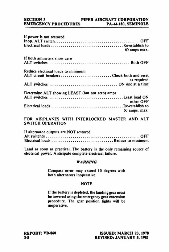
If power is not restoredlnop. ALT switch........................................... OFFElectrical loads .....................................Re-establish to
60 amps max.
If both ammeters show zeroALT switches ......................................... Both OFF
Reduce electrical loads to minimumALT circuit breakers .......................... Check both and reset
as requiredALT switches ................................... ON one at a time
Determine ALT showing LEAST (but not zero) ampsALT switches ......................................Least load ON
other OFFElectrical loads .....................................Re-establish to
60 amps. max.
FOR AlRPLANES WlTH INTERLOCKED MASTER AND ALTSWITCH OPERATION
If alternator outputs are NOT restoredAlt switches................................................ OFFElectrical loads ................................Reduce to minimum
Land as soon as practical. The battery is the only remaining source ofelectrical power. Anticipate complete electrical failure.
WARNING
Compass error may exceed 10 degrees withboth alternators inoperative.
NOTE
If the battery is depleted, the landing gear mustbe lowered using the emergency gear extensionprocedure. The gear position lights will beinoperative.
REPORT: VB-860 ISSUED: MARCH 23, 19783-8 REVISED: JANUARY 5, 1981
PIPER AIRCRAFT CORPORATION SECTION 3PA-44-180, SEMINOLE EMERGENCY PROCEDURES
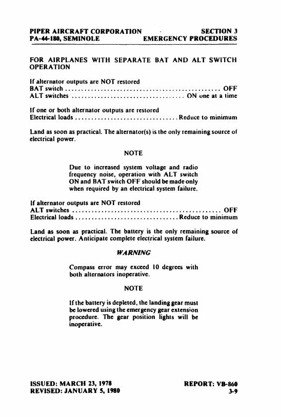
FOR AIRPLANES WITH SEPARATE BAT AND ALT SWITCHOPERATION
If alternator outputs are NOT restoredBAT switch ................................................ OFFALT switches ................................... ON one at a time
if one or both alternator outputs are restoredElectrical loads ................................Reduce to minimum
Land as soon as practical. The alternator(s) is the only remaining source ofelectrical power.
NOTE
Due to increased system voltage and radiofrequency noise, operation with ALT switchON and BAT switch OFF should be made onlywhen required by an electrical system failure.
If alternator outputs are NOT restoredALT switches .............................................. OFFElectrical loads ................................Reduce to minimum
Land as soon as practical. The battery is the only remaining source ofelectrical power. Anticipate complete electrical system failure.
WARNING
Compass error may exceed 10 degrees withboth alternators inoperative.
NOTE
If the battery is depleted, the landing Bearmustbe lowered using the emergency gear extensionprocedure. The gear position lights will beinoperative.
ISSUED: MARCH 23, 1978 REPORT: VB-860REVISED:.IANUARY 5, 1980 3-9
SECTION 3 PIPER AIRCRAFT CORPORATIONEMERGENCY PROCEDURES PA-44-180, SEMINOLE
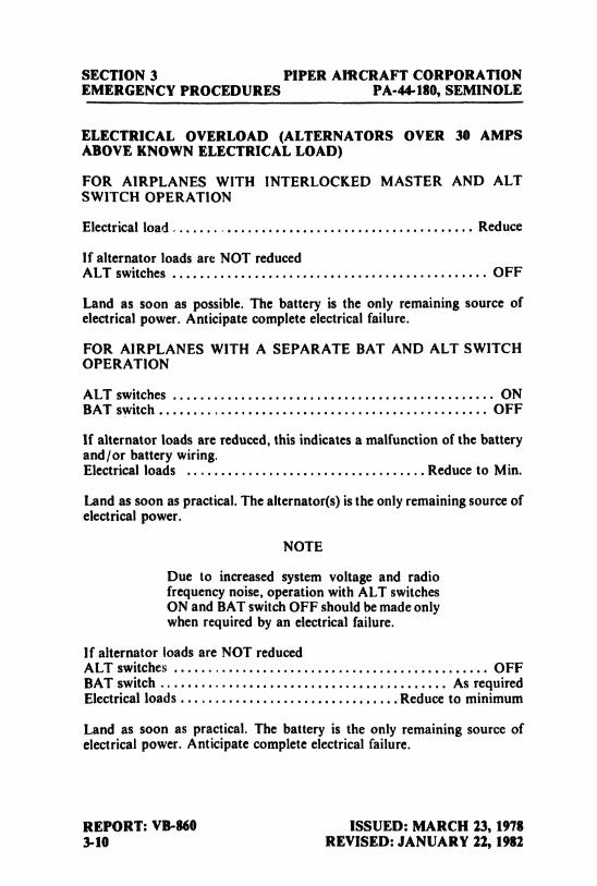
ELECTRICAL OVERLOAD (ALTERNATORS OVER 30 AMPSABOVE KNOWN ELECTRICAL LOAD)
FOR AIRPLANES WITH INTERLOCKED MASTER AND ALTSWITCH OPERATION
Electrical load ............................................ Reduce
If alternator loads are NOT reducedALT switches .............................................. OFF
Land as soon as possible. The battery is the only remaining source ofelectrical power. Anticipate complete electrical failure.
FOR AIRPLANES WITH A SEPARATE BAT AND ALT SWITCHOPERATION
ALT switches ............................................... ONBAT switch ................................................ OFF
If alternator loads are reduced, this indicates a malfunction of the batteryand/or battery wiring.Electrical loads ................................... Reduce to Min.
Land as soon as practical. The alternator(s) is the only remaining source ofelectrical power.
NOTE
Due to increased system voltage and radiofrequency noise, operation with ALT switchesON and BAT switch OFF should be made onlywhen required by an electrical failure,
If alternator loads are NOT reducedALT switches .............................................. OFFBAT switch .......................................... As requiredElectrical loads ................................Reduce to minimum
Land as soon as practical. The battery is the only remaining source ofelectrical power. Anticipate complete electrical failure.
REPORT: VB-860 ISSUED: MARCH 23, 19783-10 REVISED: JANUARY 22, 1982
PIPER AIRCRAFT CORPORATION SECTION 3PA-44-180, SEMINOLE EMERGENCY PROCEDURES
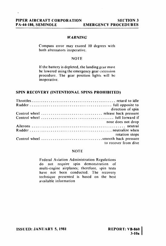
WARNING
Compass error may exceed 10 degrees withboth alternators inoperative.
NOTE
If the battery is depleted, the landing gear mustbe lowered using the emergency gear extensionprocedure. The gear position lights will beinoperative.
SPIN RECOVERY (INTENTIONAL SPINS PROHIBITED)
Throttles................... ........................ retard to idleRudder ........................................... full opposite to
direction of spinControl wheel .............. ................. release back pressureControl wheel ...................................... full forward if
nose does not dropAilerons ................................................. neutralRudder ................,... .... ................ neutralize when
rotation stopsControl wheel
................................smooth
back pressureto recover from dive
NOTE
Federal Aviation Administration Regulationsdo not require spin demonstration ofmulti-engine airplanes; therefore, spin testshave not been conducted. The recoverytechnique presented is based on the bestavailable information
ISSUED: JANUARY 5, 1981 REPORT: VB-8603-10a
SECTION 3 PIPER AIRCRAFT CORPORATIONEMERGENCY PROCEDURES PA-44-180, SEMINOLE
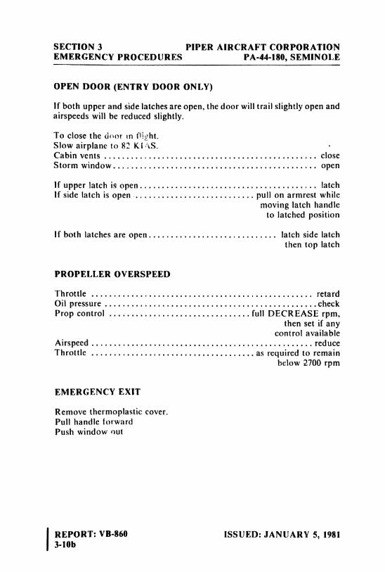
OPENDOOR(ENTRYDOORONLY)
If both upper and side latches are open, the door will trail slightly open andairspeeds will be reduced slightly.
To close the door m Di¿ht.Slow airplane to 82 Kl S.Cabin vents ................................................ closeStorm window.............................................. open
lf upper latch is open........................................ latchIf side latch is open ........................... pull on armrest while
moving latch handleto latched position
if both latches are open............................. latch side latchthen top latch
PROPELLER OVERSPEED
Throttle .................................................. retardOil pressure
................................................check
Prop control ................................full
DECREASE rpm,then set if any
control availableAirspeed..................................................reduceThrottle .....................................as required to remain
below 2700 spm
EMERGENCY EXIT
Remove thermoplastic cover.Pull handle forwardPush window out
REPORT: VB-860 ISSUED: JANUARY 5, 19813-10b
PIPER AIRCRAFT CORPORATION SECTION 3PA-44-180, SEMINOLE EMERGENCY PROCEDURES
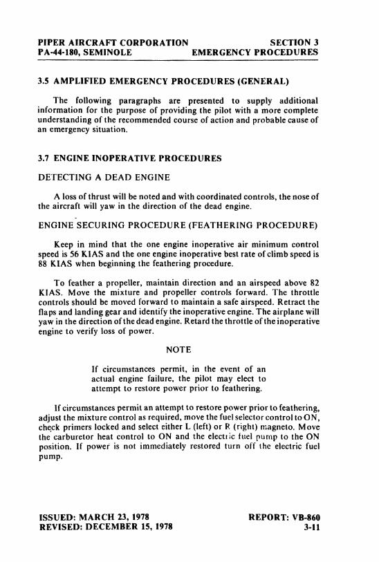
3.5 AMPLIFIED EMERGENCY PROCEDURES (GENERAL)
The following paragraphs are presented to supply additionalinformation for the purpose of providing the pilot with a more completeunderstanding of the recommended course of action and probable cause ofan emergency situation.
3.7 ENGINE INOPERATIVE PROCEDURES
DETECTING A DEAD ENGINE
A loss of thrust will be noted and with coordinated controls, the nose ofthe aircraft will yaw in the direction of the dead engine.
ENGINE SECURING PROCEDURE (FEATHERING PROCEDURE)
Keep in mind that the one engine inoperative air minimum controlspeed is 56 KIAS and the one engine inoperative best rate of climb speed is88 KIAS when beginning the feathering procedure.
To feather a propeller, maintain direction and an airspeed above 82KIAS. Move the mixture and propeller controls forward. The throttlecontrols should be moved forward to maintain a safe airspeed. Retract theflaps and landing gear and identify the inoperative engine. The airplane willyaw in the direction of the dead engine. Retard the throttle of the inoperativeengine to verify loss of power.
NOTE
If circumstances permit, in the event of anactual engine failure, the pilot may elect toattempt to restore power prior to feathering,
If circumstances permit an attempt to restore power prior to feathering,adjust the mixture control as required, move the fuel selector control to ON,che,ck primers locked and select either L (left)or R (sight) magneto. Movethe carburetor heat control to ON and the electúc fuel pump to the ONposition. If powei is not immediately restored turn off the electric fuelpump.
ISSUED: MARCH 23, 1978 REPORT: VB-860REVISED: DECEMBER 15, 1978 3-11
SECTION 3 PIPER AIRCRAFT CORPORATIONEMERGENCY PROCEDURES PA-44-180, SEMINOLE
The propellers can be feathered only while the engine is rotating above950 RPM. Loss of centrifugal force due to slowing RPM will actuate a stoppin that keeps the propeller from feathering each time the engine is stoppedon the ground. One engine inoperative performance will decrease if thepropeller of the inoperative engine is not feathered.
The propelici control of the inoperative engine should be moved to thefeather position, and the mixture control of the inoperative engine shouldbe moved to idic cut-of f.
Trim the aircraft as required and maintain a 3° to 5° bank toward theoperating engine. The ball will be ½ to ¾ out for minimum drag. The electricfuel pumps should be bff except in the case of an engine-driven fuel pumpfailure. Turn OFF the magnetos and close the cowl flaps on the inoperativeengine. Cowl flaps should be used as necessary on the operative engine.The alternator of the inoperative engine should be turned OFF and the elec-trical load reduced to prevent depletion of the battery. Move the fuel selectorcontrol for the inoperative engine to the OFF position. If necessary, considerthe use of crossfeed (refer to Fuel Management During One Engine Inop-erative Operation, paragraph 3.1I). Turn OFFthe operativeengine'selectricfuel pump.
NOTE
When an engine is feathered, the alternator,gyro air, and oil annunciator warning lightswill remain illuminated.
ENGINE FAILURE DURING TAKEOFF (Below 75 KIAS)
The one engine inoperative air minimum control speed for this airplaneis 56 KIAS under standard conditions.
NOTE
This is a stalled condition.
REPORT: VB-860 ISSUED: MARCH 23, 19783-12 REVISED: JANUARY 22, 1982
PIPER AIRCRAFT CORPORATION SECTION 3PA-44-180, SEMINOLE EMERGENCY PROCEDURES
If engine failure occurs during takeoff ground roll and 75 KIAS hasnotbeen attained, CLOSE both throttles immediately and stop straight ahead.If inadequate runway remains to stop, close the throttles and applymaximum braking. The master switch and fuel selectors should be turnedOFF. Continue path straight ahead turning to avoid obstacles as necessary.
ENGINE FAILURE DURING TAKEOFF (75 KIAS or above)
If engine failure occurs during takeoff ground roll or after lift-off withthe gear still down and 75 KIAS has been attained the course of action to betaken will depend on the runway remaining. If adequate runway remains,CLOSE both throttles immediately, land if airborne and stop straightahead. If the runway remaining is inadequate for stopping, the pilot mustdecide whether to abort the takeoff or to continue. The decision must bebased on the pilot's judgment considering loading, density altitude,obstructions, the weather, and the pilot's competence. If the decision ismade to continue the takeoff, maintain heading and airspeed, RETRACTthe landing gear, accelerate to 88 KIAS and FEATHER the inoperativeengine (referto Engine Securing Procedure).
WARNING
In certain combinations of aircraft weight,configuration, ambient conditions and speed,negative climb performance may result. Referto One Engine Inoperative Climb Performancechart, Figure 5-25.
ENGINE FAILURE DURING FLIGHT (Below 56 KIAS)
Should an engine fail during flight at an airspeed below 56 KIAS, applyrudder towards the operative engine to maintain directional control. Thethrottles should be retarded to stop the yaw force produced by theinoperative engine. Lower the nose of the aircraft to accelerate above 56KIAS and increase the power on the operative engine as the airspeedexceeds 56 KIAS.
After an airspeed above 56 KIAS has been established, an engine restartattempt may be made if altitude permits. If the restart has failed, or ifaltitude does not permit, the engine should be secured, see Engine SecuringProcedure.
ISSUED: MARCH 23, 1978 REPORT: VB-860REVISED: APRIL 10, 1981 3-13
SECTION 3 PIPER AIRCRAFT CORPORATIONEMERGENCY PROCEDURES PA-44-180, SEMINOLE
THIS PAGE INTENTIONALLY LEFT BLANK
REPORT: VB-860 ISSUED: MARCH 23, 19783-14 REVISED: DECEMBER 15, 1978
PIPER AIRCRAFT CORPORATION SECTION 3PA-44-180, SEMINOLE EMERGENCV PROCEDURES
ONE ENGINE INOPERATIVE LANDING
Complete the Engine Securing Procedure. The landing gear should notbe extended and the wing flaps should not be lowered until certain of makingthe field.
Maintain additional altitude and speed during approach, keeping inmind that landing should be made right the first time and that a go-aroundshould be avoided if at all possible.
A final approach speed of 90 KIAS and the use of 25° rather than fullwing flaps will place the airplane in the best configuration for a go-aroundshould this be necessary.
WARNING
Under some conditions of loading and densityaltitude a go-around may be impossible, and inany event the sudden application of powerduring one engine inoperative operation makescontrol of the airplane more difficult.
ONE ENGINE INOPERATIVE GO-AROUND
NOTE
A one engine inoperative go-around should beavoided if at all possible.
To execute a one engine inoperative go-around, advance the mixtureand propeller levers forward. The throttle should be advanced slowly to thefull forward position. Retract the flaps and landing gear. Maintain airspeedat the one engine inoperative best rate of climb speed of 88 KIAS. Set thetrim and cowl flaps as required.
AIR START (UNFEATHERING PROCEDURF)
Move the fuel selector for the inoperative engine to the ON position andcheck to make sure the electric fuel pump for that engine is ON. Push thepropeller control forward to the cruise RPM position and the mixtureshould be set RICH. Push in full throttle twice and then open it I/4 inch.
ISSUED: MARCH 23, 1978 REPORT: VB-860REVISED: JANUARY 5, 1981 3-15
SECTION 3 PIPER AIRCRAFT CORPORATIONEMERGENCY PROCEDURES PA-44-180, SEMINOLE
Turn ON the magneto switches and engage the starter until the propellerwindmills. The throttle should be set at reduced power until the engine iswarm. If the engine does not start, prime as necessary. The alternator switchshould then be turned ON.
3.9 FIRE
ENGINE FIRE ON TIIE GROUND
The first attempt to extinguish the fire is to try to draw thefire back intothe engine. If the engine has not started, move the mixture control to idlecut-off and open the throttle. Begin to crank the engine with the starter in anattempt to pull the fire into the engine.
If the engine has already started and is running, continue operating totry to pull the fire into the engine.
In either case (above),if the fire continues longer than a few seconds thefire should be extinguished by the best available external means.
If an external fire extinguishing method is to be applied move the fuelselector valves to OFF and the mixture to idle cut-off.
ENGINE FIRE IN FLIGHT
The possibility of an engine fire in flight is extremely remote. Theprocedure given below is general and pilot judgmentshould be the decidingfactor for action in such an emergency.
If an engine fire occurs in flight, place the fuel selector of the affectedengine in the OFF position and close its throttle. Feather the propeller onthe faulty engine. Move the mixture control to idle cut-off. The cowl flapshould be open. A landing should be made if terrain permits.
REPORT: VB-860 ISSUED: MARCH 23, 19783-16 REVISED: JANUARY 5, 1981
PIPER AIRCRAFT CORPORATION SECTION 3PA-44-180, SEMINOLE EMERGENCY PROCEDURES
3.11 FUEL MANAGEMENT DURING ONE ENGINE INOPERATIVEOPERATION
A crossfeed is provided to increase range during one engine inoperativeoperation. Use crossfeed in level flight only.
CRUISING
When using fuel from the fuel tank on the same side as the operatingengine, the fuel selector of the operating engine should be ON and the fuelselector for the inoperative engine should be OFF. The electric fuel pumpsshould be OFF except in the case of an engined riven fuel pump failure. If anengine4riven fuel pump has failed, the electric fuel pump on the operatingengine side must be ON.
Increased range is available by using fuel from the tank on the oppositeside of the operating engine. For this configuration the fuel selector of theoperating engine must be on X-FEED (crossfeed)and the fuel selector of theinoperative engine must be OFF. The electric fuel pumps should be OFF.Crossfeed is approved for level cruise flight only.
LANDING
During the landing sequence, the fuel selector of the operating enginemust be ON and the fuel selector of the inoperative engine OFF. The electricfuel pump of the operating engine should be ON.
3.13 ENGINE-DRIVEN FUEL PUMP FAILURE
Loss of fuel pressure and engine power can be an indication of failure of
the engine-driven fuel pump. Should these occur and engine-driven fuelpump failure is suspected, turn ON the electric fuel pump.
CAUTION
If normal engine operation and fuel flow is notimmediately re-established, the electric fuelpump should be turned off. The lack of a fuelflow indication while on the electric fuel pumpcould indicate a leak in the fuel system, or fuelexhaustion
ISSUED: MARCH 23, 1978 REPORT: VB-860REVISED: MARCH 4, 1989 3-17
SECTION 3 PIPER AIRCRAFT CORPORATIONEMERGENCY PROCEDURES PA-44-180, SEMINOLE
3.15 LANDING GEAR UNSAFE WARNINGS
The red landing gear light will illuminate when the landing gear is intransition between the full up position and the down and locked position.The pilot should recycle the landing gear if continued illumination of thelight occurs. Additionally, the light will illuminate when the gear warninghorn sounds. The gear warning horn wili sound at low throttle settings if thegear is not down and locked, and when wing flaps are in the second or thirdnotch position and the gear is not down and locked.
3.17 MANUAL EXTENSION OF THE LANDING GEAR
Several items should be checked prior to extending the landing gearmanually. Check for popped circuit breakers and ensure the master switch isON. Then check the alternators. If it is daytime, turn OFF the navigationlights.
To execute a manual extension of the landing gear, power should bereduced to maintain airspeed below 100 KIAS. Place the landing gearselector switch in the GEAR DOWN position and puli the emergency gearextension knob. Check for 3 green indicator lights.
WARNING
If the emergency gear extension knob has beenpulled out to lower the gear due to a gearsystem matfunction, leave the control in itsextended position until the airplane has beenput on jacks to check the proper function ofthe landing gears hydraulic and electricalsystems.
3.19 GEAR-UP EMERGENCY LANDING
An approach should be made with power at a normal airspeed with theflaps up. The flaps are left up to reduce wing and flap damage. Close thethrottles just before touchdown. Turn OFF the master and ignition switchesand move the fuel selector valve controls to OFF. Contact to the surfaceshould be made at a minimum airspeed.
REPORT: VB-860 ISSUED: MARCH 23, 19783-18 REVISED: SEPTEMBER 14, 1979
PIPER AIRCRAFT CORPORATION SECTION 3PA-44-180, SEMINOLE EMERGENCY PROCEDURES
3.21 GYRO SUCTION FAILURES
A malfunction of the instrument suction system will be indicated by areduction of the suction reading on the gauge. A red button annunciator willshow in case of a feathered engine or vacuum pump failure
in the event of a suction system malfunction, (suction lower than 4.5inches of mercury) increase engine RPM to 2700. Descend to an altitude atwhich 4.5 inches of mercury suction can be maintained, if possible. Theelectric turn indicator should be used to monitor the performance of thedirectional and attitude indicators.
3.23 ELECTRICAL FAILURES
If one ammeter shows zero output, turn its switch OFF, reduce electricalloads to a minimum and check its circuit breaker. Reset if required. TurnALT switch ON. If the alternator remains inoperative, repeat the aboveprocedure one more time. If the alternator still remains inoperative, turnALT switch OFF, maintain an electrical load of 60 amps maximum on theoperating alternator and exercise judgment regarding continued flight.
If both ammeters show zero output, turn both ALT switches OFF andreduce electrical loads to a minimum. Check both alternator circuit breakersand reset if required. Turn ALT switches ON one at a time while observingthe ammeters. The alternator showing the LEAST (but not zero) output,should be turned ON and the other alternator should be left OFF. Electricalloads may be re-established as required to a maximum of 60 amps.
FOR AIRPLANES WITH INTERLOCKED MASTER AND ALTSWITCH OPERATION
If neither alternator output can be restored, both alternator switchesshould be left OFF. Reduce electrical load to essential systems and land assoon as practical. The battery is the only remaining source of electricalpower.
WARNING
Compass error may exceed 10 degrees withboth alternators inoperative
ISSUED: MARCH 23, 1978 REPORT: VB-860REVISED: JANUARY 5, 1981 3-19
SECTION 3 PIPER AIRCRAFT CORPORATION: EMERGENCY PROCEDURES PA-44-180, SEMINOLE
NOTE
If the battery is depleted, the landing gear mustbe lowered using the emergency gear extensionprocedure. The gear position lights will beinoperative.
FOR AlRPLANES WITH SEPARATE BAT AND ALT SWlTCHOPERATION
If alternator outputs are not restored, turn BAT switch OFF, ALTswitches OFF, then ON one at a time. If one or both alternator outputs arerestored, leave the BAT switch OFF and land as soon as practicaL Thiscondition is an indication of a battery and/or battery wiring malfunction.
NOTE
Operation with the ALT switches ON and theBAT switch OFF should be made only whenrequired by an electrical failure, due toincreased system voltage and radio frequencynoise.
If neither alternator output can be restored, turn both ALT switchesOFF and turn the BAT switch ON as required. Maintain a minimum elec-trical load and land as soon as practical. The battery is the only remainingsource of electrical power.
WARNING
Compass error may exceed 10 degrees withboth alternators inoperative.
NOTE
if the battery is depleted, the landing gear mustbe loweied using the emergency extensionprocedure The green position lights will beinoperative
REPORT: VB-860 ISSUED: MARCH 23, 19783-20 REVISED: JANUARY 5, 1981
PIPER AIRCRAFT CORPORATION SECTION 3PA-44-180, SEMINOLE EMERGENCY PROCEDURES
ELECTRICAL OVERLOAD (ALTERNATORS OVER 30 AMPSABOVE KNOWN ELECTRICAL LOAD)
If abnormally high alternator outputs are observed and persist (morethan 30 amps above known electrical load for the operating conditions),they may be caused by a low battery, a battery fault or other abnormal elec-trical load. If the cause is a low battery, the indication should begin todecrease toward normal within 5 minutes. If the overload condition persistsproceed as follows:
For airplanes with interlocked MASTER and ALT switches, reduceelectrical loads by turning off non-essential electrical equipment. If the loadscannot be reduced, turn the ALT switches OFF, maintain minimum elec-trical load and land as soon as practical. The battery is the only remainingsource of electrical power. Also anticipate complete electrical failure.
WARNING
Compass error may exceed 10 degrees withboth alternators inoperative.
NOTE
If the battery is depleted, the landing gear mustbe lowered using the emergency extensionprocedure. The green position lights will beinoperative.
For airplanes with separate BAT and ALT switch operation, turn theBAT switch OFF and the ammeter indication should decrease Turn theBAT switch ON and continue to monitor the ammeter Should the alter-nator outputs not decrease within 5 minutes, turn the BAT switch OFF andland as soon as practical. All electrical loads are being supplied by thealternators.
NOTE
Operation with the ALT switches ON and theBAT switch OFF should be made only whenrequired by an electrical failure, due toincreased system voltage and radio frequencynoise
ISSUED: MARCH 23, 1978 REPORT: VB-860REVISED: JANUARY 5, 1981 3-21
SECTION 3 PIPER AIRCRAFT CORPORATIONEMERGENCY PROCEDURES PA-44-180, SEMINOLE
3.25 SPINS
Intentional spins are prohibited in this airplane. In the event a spin isencountered unintentionally, immediate recovery actions must be taken.
To recove• from an unintentional spin, immediately retard the throttlesto the idle position. Apply full rudder opposite the direction of the spinrotation. Let up all back pressure on the control wheel. If the nose does notdrop, immediately push the control wheel full forward. Keep the aileronsneutral. Maintain the controls in these positions until spin rotation stops,then neutralize the rudder. Recovery from the resultant dive should be withsmooth back pressure on the control wheel. No abrupt control movementshould be used during recovery from the dive, as the positive limitmaneuvering load factor may be exceeded.
NOTE
Federal Aviation Administration Regulationsdo not require spin demonstration of multi-engine airplanes; therefore, spin tests have notbeen conducted. The recovery techniquepresented is based on the best availableinformation.
3.27 OPEN DOOR (ENTRY DOOR ONLY)
The cabin door is double latched, so the chances of its springing open inflight at both the top and side are remote. However, should you forget theupper latch, or not fully engage the side latch, the door may spring partiallyopen. This will usually happen at takeoff or soon afterward. A partiallyopen door will not affect normalflightcharacteristics, and a normal landingcan be made with the door open.
If both upper and side latches are open, the door will trail slightly open,and airspeed will be reduced slightly.
To close the door in flight, slow the airplane to 82 KlAS, close the cabinvents and open the storm window. If the top latch isopen,1atch it. If the sidelatch is open, pull on the armrest while moving the latch handle to thelatched position. If both latches an open, close the side latch then the toplatch.
REPORT: VB-860 ISSUED: MARCH 23, 19783-12 REVISED: JANUARY 5, 1981
PIPER AIRCRAFT CORPORATION SECTION 3PA-44-180, SEMINOLE EMERGENCY PROCEDURES
3.29 PROPELLER OVERSPEED
Propeller overspeed is usually caused by a malfunction in the propellergovernor which allows the propeller blades to rotate to full low pitch.
If propeller overspeed should occur, retard the throttle The propellercontrol should be moved to full "DECREASE rpm"and then set if any con-trol is available. Airspeed should be reduced and the throttle should be usedto maintain 2700 RPM.
3.31 COMBUSTION HEATER OVERHEAT
In the event of an overheat condition, the fuel, air and ignition to theheater is automatically cut off Do not attempt to restart the heater until ithas been inspected and the cause of the malfunction has been determinedand corrected.
3.33 EMERGENCY DESCENT
In the event an emergency descent becomes necessary, CLOSE thethrottles and move the propeller controls full FORWARD Adjust themixture control as necessary to attain smooth operation Extend the landinggear at 140 KIAS and maintain this airspeed
3.35 EMERGENCY EXIT
The pilot's left side window is an emergency exit. This is to be used whenemergency egress becomes necessary on the ground only. The emergencyexit release handle is located beneath the thermoplastic cover on the verticalpost between the ist and 2nd left side windows. To exit the aircraft, removethe thermoplastic cover, push the release handle forward and then push thewindow out. The window then will fall free from the fuselage.
ISSUED: JANUARY 5, 1981 REPORT: VB-8603-23
SECTION 3 PIPER AIRCRAFT CORPORATIONEMERGENCY PROCEDURES PA-44-180, SEMINOLE
3.37 CARBURETOR ICIÑG
Under certain moist atmospheric conditions at temperatures of -5°C to20°C, it is possible for ice to form in the induction system, even in summerweather. This is due to the high air velocity through the carburetor venturiand the absorption of heat from this air by vaporization of the fuel.
To avoid this, carburetor preheat is provided to replace the heat lost byvaporization. Carburetor heat should be full on when carburetor ice isencountered. Adjust mixture for maximum smoothness.
IREPORT: VB-860 ISSUED: JANUARY 5, 19813-24
TABLE OF CONTENTS
SECTION 4
NORMAL PROCEDURES
Paragraph PageNo. No
4.1 General ................. . ..... .............. 4-14.3 Airspeeds For Safe Operations ...................... 4-24.5 Normal Procedures Checklist........................ 4-3
Preparation.............. . .. . .............. 4-3Pref1ight Check.............. . ............. 4-3Before Starting Engines .......................... 4-5Starting Engines................................. 4-5Starting Engines in Cold Weather (Below 10°F) ..... 4-6Starting Engines When Hot....................... 4-6Starting Engines When Flooded ................... 4-7Starting Engines With External Power ............. 4-7Warm-Up ................. ... ............. 4-7Taxiing........................ .............. 4-8Before Takeoff - Ground Check ................... 4-8Takeoff ............... ............ 4-9Takeoff Climb ................. . ............. 4-10Cruise C1imb................ . . ............ 4-10Cruising............... .... . . .............. 4-10Descent .............. . ............. 4-11Approach and Landing........................... 4-11Go-Around ................. .. . . ........... 4-IlAfter Landing............... . ............ 4-11Shutdown .................. .. ........... 4-I2Parking ......................... . . ..... 4-12
4.7 Amplified Normal Procedures (General) ... .. ....... 4-12a49 Preparation.............. .. . . ............ 4-12a4.11 Preflight Check............... .. .............. 4-12a4 13 Before Starting Engines .............. ............ 4-134 15 Starting Engines.............. . .............. 4-14
IREPORT: VB-860
4-i
TABLE OF CONTENTS (cont)
SECTION 4 (cont)
Paragraph'
PageNo. No.
4.16 Starting Engines in Cold Weather (Below 10° F) . . . . . . . 4-144.17 Starting Engines When Hot ......................... 4-154.19 Starting Engines When Flooded ..................... 4-154.21 Starting Engines With External Power . . . . . . . . . . . . . . . 4-154.23 Warm-Up ........................................ 4-174.25 Taxiing........................................... 4-174.27 Before Takeoff- Ground Check ..................... 4-174.29 Takeoff .......................................... 4-194.31 Climb............................................ 4-204 33 Cruising.......................................... 4-214.35 Descent .......................................... 4-224.37 Approach and Landing............................. 4-234.39 Go-Around ....................................... 4-254.41 After Landing..................................... 4-254.43 Shutdown ........................................ 4-254.45 Parking .......................................... 4-254.47 Turbulent Air Operation............................ 4-264.49 VssE - Intentional One Engine Inoperative Speed ...... 4-264.51 YMCA - Air Minimum Control Speed................. 4-264.53 Stalls ............................................ 4-27
REPORT: VB-8604-ii
PIPER AIRCRAFT CORPORATION SECTION 4PA-44-180, SEMINOLE NORMAL PROCEDURES
SECTION 4
NORMAL PROCEDURES
4.1 GENERAL
This section describes the recommended procedures for the conduct ofnormal operations for the Seminole. All of the required (FAA regulations)procedures and those necessary for the safe operation of the airplane asdetermined by the operating and design features of the airplane are pre-sented.
Normal procedures associated with those optional systems and equip-ment which require handbook supplements are provided by Section 9(Supplements).
These procedures are provided to present a source of reference andreview and to supply information on procedures which are not the same forall aircraft. Pilots should familiarize themselves with the procedures givenin this section in order to become proficient in the normal operations of theairplane.
The first portion of this section consists of a short form check list whichsupplies an action sequence for normal operations with little emphasis onthe operation of the systems.
The remainder of the section is devoted to amplified normal procedureswhich provide detailed information and explanations of the procedures andhow to perform them. This portion of the section is not intended for use asan in-flight reference due to the lengthly explanations. The short form checklist should be used for this purpose.
All data given is for both two and three blade propellers unless otherwisenoted.
ISSUED: MARCH 23, 1978 REPORT: VB-860REVISED: DECEMBER 15, 1978 4-1
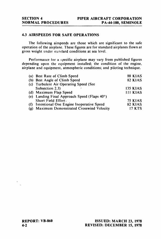
SECTION 4 PIPER AIRCRAFT CORPORATIONNORMAL PROCEDURES PA-44-180, SEMINOLE
4.3 AIRSPEEDS FOR SAFE OPERATIONS
The following airspeeds are those which are significant to the safeoperation of the airplane. These figures are for standard airplanes flown atgross weight under standard conditions at sea level.
Performance for a specific airplane may vary from published figuresdepending upon the equipment installed; the condition of the engine,airplane and equipment, atmospheric conditions; and piloting technique.
(a) Best Rate of Climb Speed 88 KIAS(b) Best Angle of Climb Speed 82 KIAS(c) Turbulent Air Operating Speed (See
Subsection 2.3) - 135 KIAS(d) Maximum Flap Speed 111 KIAS(e) Landing Final Approach Speed (Flaps 40°)
Short Field Effort. 75 KIAS(f) Intentional One Engine Inoperative Speed 82 KIAS(g) Maximum Demonstrated Crosswind Velocity 17 KTS
REPORT: VB-860 ISSUED: MARCH 23, 19784-2 REVISED: DECEMBER 15, 1978
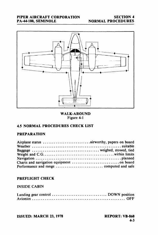
PIPER AIRCRAFT CORPORATION SECTION 4PA-44-180, SEMINOLE NORMAL PROCEDURES
WALK-AROUNDFigure 4-1
4.5 NORMAL PROCEDURES CHECK LIST
PREPARATION
Airplane status . . . . . . . . . . . . . . . . . . . . . . . . .
.airworthy,
papers on boardWeather
.................................................suitable
Baggage.....................................weighed,
stowed, tiedWeight and C.G.......................................within limitsNavigation
...............................................planned
Charts and navigation equipment . . . . . . . . . . . . . . . . . . . . . . . . ..on board
Performance and range .......................... computed and safe
PREFLIGHT CHECK
INSIDE CABIN
Landing gear control .............................. DOWN positionAvionics ................................................... OFF
ISSUED: MARCH 23, 1978 REPORT: VB-8604-3
SECTION 4 PIPER AIRCRAFT CORPORATIONNORMAL PROCEDURES PA-44-180, SEMINOLE
Afaster switch ............................................... ()NLanding gear lights......................................3 GREENFuelquantity.................................adequate phis reserveCowinaps ................................................OPET4Master switch .............................................. OFFIgnitionswitches... .. ..................................... OFFMixturecontrols.......................................idlecut-offTrini indicators ........................................... neutralFlaps.............................................check operationControls .................................................... freePitot and static systems ...................................... drainErnpty seats
...........................................fasten
beltsEmergency exit
..................................closed
and locked
OUTSlDE CABIN
Fuel sump drains ........................................... drainRightwing,aileron and Rap........................... check,no iceRight naain gear ......................................... no leaksStrut .............................................proper innationTire
.......................................................check
Right wing tip ..............................................check
Right leading edge ................................... check,no iceFuel cap ................................. open,check quantity and
color,secureRight engine nacelle ......................................check
oilRight propeller .............................................check
Cowl flaps ......................................OPEN and secureFueldrains.................................................drainNose section................................................checkNose gear ............................................... no leaksStrut .............................................proper innationTire .......................................................check
Trav bar ......................................renloved and stowedLanding light...............................................checkYVindshield ................................................. cleanLeft wing, engine nacelle and landing gear................... check as
on right sideStall warning vanes
.........................................check
Pitot/static mast.................................... elear,checkedDorsal fin air scoop ......................................... clearEmpennage
.........................................check,no
iceStabilator ................................................... free
REPORT: VB-860 ISSUED: MARCH 23, 19784-4 REVISED: JULY 24, 1981
PIPER AIRCRAFT CORPORATION SECTION 4PA-44-180, SEMINOLE NORMAL PROCEDURES
Antennas..................................................check
Navigation and landing lights.................................checkBaggage door.................................... secure and locked
BEFORE STARTING ENGINES
Seats ................................................... adjustedSeat belts and harness ................................ fasten/adjust
check inertia reelParking brake ................................................ setCircuit breakers................................................inRadios .................................................... OFFCowl flaps ................................................ OPENCarburetor heat............................................. OFFAlternators.................................................. ONProp sync............................................. MANUAL
STARTING ENGINES
Fuel selector ................................................ ONMixture .................................................. RICHThrottle ........................................... 1/4 inch openPropeller............................................ FORWARDMaster switch ............................................... ONElectric fuel pump ........................................... ONIgnition switches ............................................. ONPropeller................................................... clearPrimer................................................as requiredStarter....................................................engageThrottle
..................................adjust
when engine startsOil pressure
................................................check
Repeat for opposite engine.Alternators.................................................checkGyro suction ...............................
..............check
NOTE
When starting at ambient temperatures +20°Fand below, operate first engine started withalternator ON (at max charging rate not toexceed 1500 RPM) for 5 minutes minimumbefore initiating start on second engine.
ISSUED: MARCH 23, 1978 REPORT: VB-860REVISED: MARCH 4, 1989 4-5
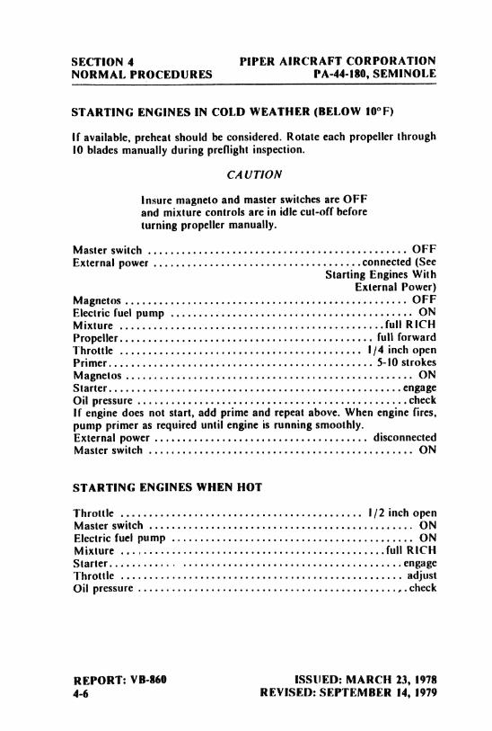
SECTION 4 PIPER AIRCRAFT CORPORATIONNORMAL PROCEDURES PA-44-180, SEMINOLE
STARTING ENGINES IN COLD WEATHER (BELOW 10°F)
If available, preheat should be considered. Rotate each propeller through10 blades manually during preflight inspection.
CAUTION
Insure magneto and master switches are OFFand mixture controls are in idle cut-off beforeturning propeller manually.
Master switch .............................................. OFFExternal power
.....................................connected
(SeeStarting Engines With
External Power)Magnetos .................................................. OFFElectric fuel pump ........................................... ONMixture
...............................................full
RICHPropeller............................................. full forwardThrottle ........................................... 1/4 inch openPrimer............................................... 5-10 strokesMagnetos ................................................... ONStarter....................................................engageOil pressure
................................................check
if engine does not start, add prime and repeat above. When engine fires,pump primer as required until engine is running smoothly.External power ...................................... disconnectedMaster switch ............................................... ON
STARTING ENGINES WHEN HOT
Throttle ........................................... 1/2 inch openMaster switch ............................................... ONElectric fuel pump ........................................... ONMixture
...............................................full
RICHStarter............ .......................................engage
Throttle .................................................. adjustOil pressure
..............................................,.check
REPORT: VB-860 ISSUED: MARCH 23, 19784-6 REVISED: SEPTEMBER 14, 1979
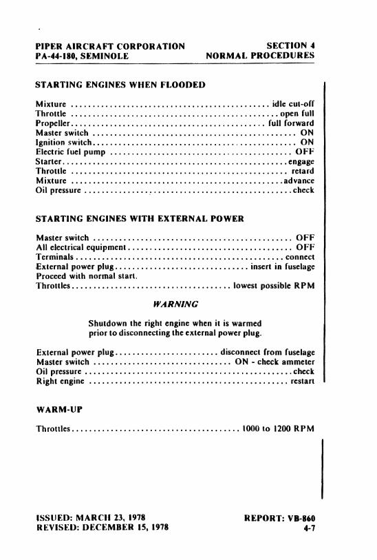
PIPER AIRCRAFT CORPORATION SECTION 4PA-44-180, SEMINOLE NORMAL PROCEDURES
STARTING ENGINES WHEN FLOODED
Mixture .............................................. idle cut-offThrottle ................................................open fullPropeller............................................. full forwardMaster switch ............................................... ONIgnition switch............................................... ONElectric fuel pump .......................................... OFFStarter....................................................engageThrottle .................................................. retardMixture
.................................................advance
Oil pressure................................................check
STARTING ENGINES WITH EXTERNAL POWER
Master switch .............................................. OFFAll electrical equipment...................................... OFFTerminals ................................................ connectExternal power plug............................... insert in fuselageProceed with normal start.Throttles..................................... lowest possible RPM
WARNING
Shutdown the right engine when it is warmedprior to disconnecting the external power plug.
External power plug........................ disconnect from fuselageMaster switch ................................ ON - check ammeterOil pressure
................................................check
Right engine .............................................. restart
WARM-UP
Throttles....................................... 1000 to 1200 RPM
ISSUED: MARCH 23, 1978 REPORT: VB-860REVISED: DECEMBER 15, 1978 4-7
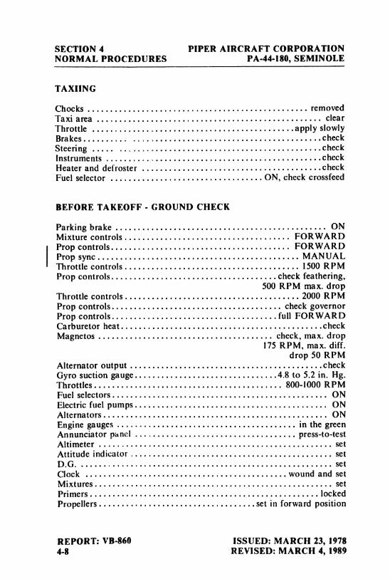
SECTION 4 PIPER AIRCRAFT CORPORATIONNORMAL PROCEDURES PA-44-180, SEMINOLE
TAXIING
Chocks ................................................. reniovedTaxi area .................................................. clearThrottle
.............................................apply
shawlyBrakes..........
..........................................check
Steering .....
.............................................check
Instrunaents..........,.....................................check
Heater and defroster........................................check
Fuel selector ..................................ON, check crossfeed
BEFORE TAKEOFF - GROUND CHECK
Parking brake ............................................... ONMixture controls..................................... FORWARDProp controls........................................ F13RYVAURI)Prop sync............................................. MANUALThrottle controls ....................................... 1500 RPA4Prop controls.....................................check feathering,
500 RPhi naax.dropThrottle controls.......................................2000 RPh4Prop controls...................................... check governorProp controls.....................................full FORWARDCarburetor heat.............................................checkAdagnetos ....................................... check,naax.drop
175 RPM, max. diff.drop 50 RPAf
Alternator output...........................................check
Gyro suction gauge................................4.8 to 5.2 in. Hg.Throttles.......................................... 800-1000 BUPhiFuel selectors................................................ ONElectric fuelpunaps........................................... ONAlternators.................................................. ()NEngine gauges ........................................ in the greenAnnunciator panel .................................... press-to-testAdtirneter .................................................... setAttitude indicator ............................................. setOs.G. ........................................................ setClock
.............................................wound
and seth4ixtures..................................................... setPrimers...................................................lockedPropellers...................................set in forward position
REPORT: VB-860 ISSUED: MARCH 23, 19784-8 REVISED: MARCH 4, 1989
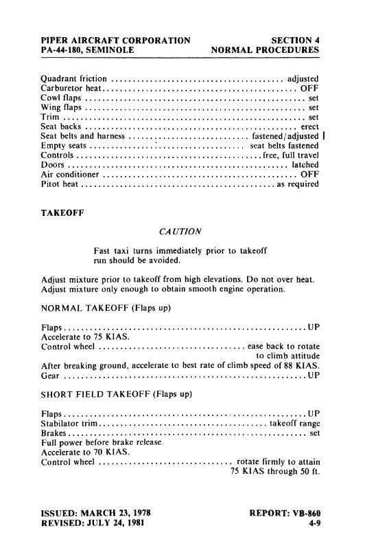
PIPER AIRCRAFT CORPORATION SECTION 4PA-44-180, SEMINOLE NORMAL PROCEDURES
Quadrantfriction ........................................ adjustedCarburetor heat............................................. OFFCowl flaps ................................................... setWing flaps ............................... ................... setTrim ........................................................ setSeat backs ................................................. erectSeat belts and harness . . . . . . . . . . . . . . . . . . . . . . .. . . . . fastened adjusted iEmpty seats .................................... seat belts fastenedControls
...........................................free,
full travelDoors ................................................... latchedAir conditioner ............................................. OFFPitot heat ............................................. as required
TAKEOFF
CAUTION
Fast taxi turns immediately prior to takeoffrun should be avoided.
Adjust mixture prior to takeoff from high elevations. Do not over heat.Adjust mixture only enough to obtain smooth engine operation.
NORMAL TAKEOFF (Flaps up)
Flaps........................................................UPAccelerate to 75 KIAS.Control wheel .................................. ease back to rotate
to climb attitudeAfter breaking ground, accelerate to best rate of climb speed of 88 KIAS.IGear ........................................................UP
SHORT FIELD TAKEOFF (Flaps up)
Flaps........................................................UPStabilator trim....................................... takeoff rangeBrakes....................................................... setFull power before brake release.Accelerate to 70 KIAS.Control wheel . . . . . . . . . . . . . . . . . . . . . . . . . . . . . . . rotate firmly to attain
75 KIAS through 50 ft.
ISSUED: MARCH 23, 1978 REPORT: VB-860REVISED: JULY 24, 1981 4-9
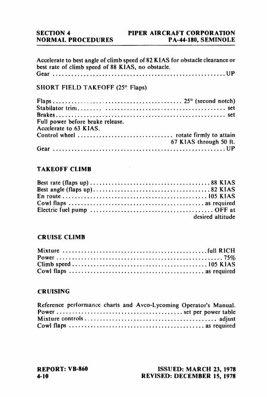
SECTION 4 PIPER AIRCRAFT CORPORATIONNORMAL PROCEDURES PA-44-180, SEMINOLE
Accelerate to best angle of climb speed of 82 KIAS for obstacle clearance orbest rate of climb speed of 88 KIAS, no obstacle.Gear ........................................................UP
SHORT FIELD TAKEOFF (25° Flaps)
Flaps.......................................... 25° (secondnotch)Stabilator trim........ ....................................... setBrakes....................................................... setFull power before brake release.Accelerate to 63 KIAS.Control wheel ............................... rotate firmly to attain
67 KIAS through 50 ft.Gear ........................................................UP
TAKEOFF CLIMB
Best rate(flaps up).......................................88 KIASBest angle (flaps up)......................................82 KIASEn route............................................... 105 KIASCowl flaps ............................................as requiredElectric fuel pump ........................................ OFF at
desired altitude
CRUISE CLIMB
Mixture ...............................................full
RICHPower
......................................................75%
Climb speed............................................105 KIASCowl flaps ............................................ as required
CRUISlNG
Reference performance charts and Avco-Lycoming Operator's Manual.Power ......................................... set per power tableMixture controls........................................... adjustCowl flaps ............................................as required
REPORT: VB-860 ISSUED: MARCH 23, 19784-10 REVISED: DECEMBER 15, 1978
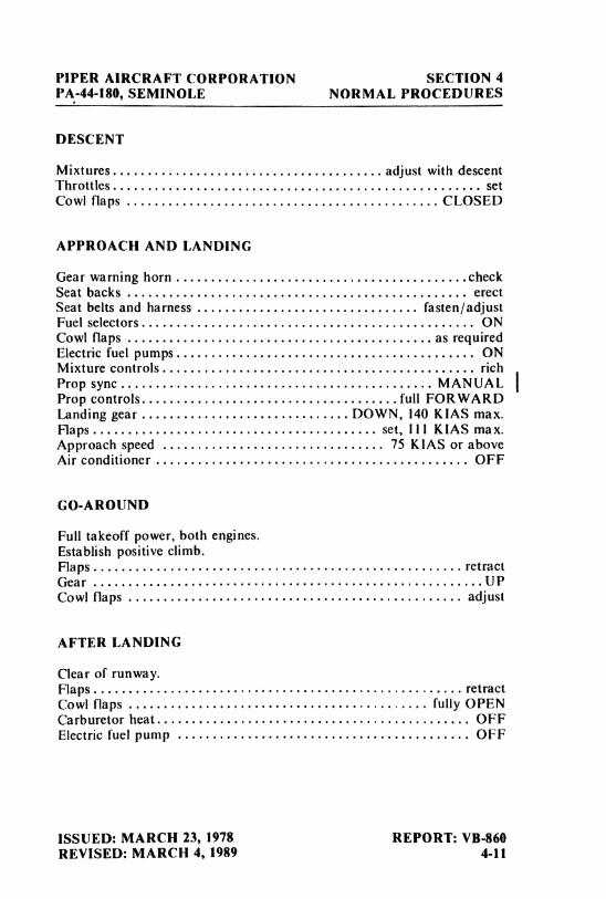
PIPER AIRCRAFT CORPORATION SECTION 4PA-44-180, SEMINOLE NORMAL PROCEDURES
DESCENT
Mixtures....................................... adjust with descentThrottles..................................................... setCowl flaps ................. ........... ............... CLOSED
APPROACH AND LANDING
Gear warning horn..........................................check
Seat backs ................................................. erectSeat belts and harness ................................ fasten/adjustFuel selectors............... ................................ ONCowl flaps ............................................as requiredElectric fuel pumps........................................... ONMixture controls............................................. richProp sync............................................. MANUALProp controls.....................................full FORWARDLanding gear ..............................DOWN, 140 KIAS max.Flaps......................................... set, 111 KIAS max.Approach speed ................................ 75 KIAS or aboveAir conditioner ............................................. OFF
GO-AROUND
Full takeoff power, both engines.Establish positive climb.Flaps.......................... .......................... retractGear ........................................................UPCowl flaps ................................................ adjust
AFTER LANDING
Clear of runway.Flaps..................................................... retractCowl flaps ........................................... fully OPENCarburetor heat............................................. OFFElectric fuel pump .......................................... OFF
ISSUED: MARCH 23, 1978 REPORT: VB-860REVISED: MARCH 4, 1989 4-11
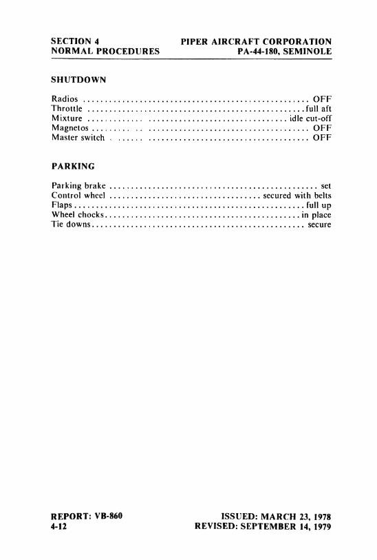
SECTION 4 PIPER AIRCRAFT CORPORATIONNORMAL PROCEDURES PA-44-180, SEMINOLE
SHUTDOWN
Radios .................................................... OFFThrottle ............. ..
.................................full aftMixture ............ ................................ idle cut-offMagnetos ......... . .. ......... ........ .............. OFFMaster switch . ...... ..................................... OFF
PARKING
Parking brake ................................................ setControl wheel ............... ................... secured with beltsFlaps.....................................................full upWheel chocks................ ...
........................in
placeTie downs................................................. secure
REPORT: VB-860 ISSUED: MARCH 23, 19784-12 REVISED: SEPTEMBER 14, 1979
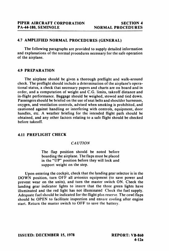
PIPER AIRCRAFT CORPORATION SECTION 4PA-44-180, SEMINOLE NORMAL PROCEDURES
4.7 AMPLIFIED NORMAL PROCEDURES (GENERAL)
The following paragraphs are provided to supply detailed informationand explanations of the normal procedures necessary for the safe operationof the airplane.
4.9 PREPARATION
The airplane should be given a thorough preflight and walk-aroundcheck. The preflight should include a determination of the airplane's opera-tional status, a check that necessary papers and charts are on board and inorder, and a computation of weight and C.G. limits, takeoff distance andin-flight performance. Baggage should be weighed, stowed and tied down.Passengers should be briefed on the use of seat belts and shoulder harnesses,oxygen, and ventilation controls, advised when smoking is prohibited, andcautioned against handling or interfering with controls, equipment, doorhandles, etc. A weather briefing for the intended flight path should beobtained, and any other factors relating to a safe flight should be checkedbefore takeoff.
4.11 PREFLIGHT CHECK
CAUTION
The flap position should be noted beforeboarding the airplane. The flaps must be placedin the "UP" position before they will lock andsupport weight on the step.
Upon entering the cockpit, check that the landing gear selector is in theDOWN position, turn OFF all avionics equipment (to save power andprevent wear on the units), and turn the master switch ON. Check thelanding gear indicator lights to insure that the three green lights haveilluminated and the red light has not illuminated Check the fuel supply.Adequate fuel should be indicated for the flight plus reserve. The cowl flapsshould be OPEN to facilitate inspection and ensure cooling after enginestart. Return the master switch to OFF to save the battery.
ISSUED: DECEMBER 15, 1978 REPORT: VB-8604-12a
SECTION 4 PIPER AIRCRAFT CORPORATIONNORMAL PROCEDURES PA-44-180, SEMINOLE
Check that the ignition switches are OFF and move the mixture controlsto idle cut-off to prevent an inadvertent start while checking the propellers.Move the trim controls to neutral so that the tabs can be checked for align-ment. Extend and retract the flaps to check for proper operation. This checkis performed prior to engine start so that you can hear any noise that mightindicate binding The controls should be free and move properly. Drain thepitot and static system lines through the drains located on the side panel nextto the pilot's seat. Fasten the seat belts on the empty seats. Before leaving thecockpit, check the emergency exit for security, verifying that the emergencyexit latch is locked and all components are in place.
CAUTION
If the emergency exit is unlatched in flight itmay separate and damage the exterior of theairplane.
The first item to check during the walk-around is the fuel sumps. Drainand check for foreign matter. Check the right wing, aileron and flap hingesand surfaces for damage and ice. Make a close check of the right landinggear for leaks, proper piston exposure under a static load (2.6 inches) andthat the tires are properly inflated and not excessively worn. The right wingtip and leading edge should be free from ice and damage.
Open the fuel cap to check the quantity and color of the fuel. Check fuelquantity with the calibrated dipstick provided for that purpose. For anaccurate reading, the airplane should be on level ground. The cap ventshould be free of obstructions. Secure the fuel cap properly. Check the oilquantity (four-to six quarts). Six quarts are required for maximum range.Secure the inspection door. Check the right propeller for nicks or leaks. Thespinner should be secure and undamaged (checkclosely for cracks). Thecowl flaps should be open and secure.
Check the nose section for damage and the nose landing gear for leaksand proper strut inflation. Under a normal static load, 2.7 inches of strutshould be exposed Check the tire for wear and proper inflation. If the towbar was used, remove and stow. Check the condition of the landing light.
At the front of the airplane, the windshield should be clean, secure andfree from cracks or distortion. Moving around to the left wing, check thewing, engine nacelle and landing gear as described for the right side. Don'tforget to check the fuel and oil.
REPORT: VB-860 ISSUED: DECEMBER 15, 19784-12b REVISED: JULY 24, 1981
PIPER AIRCRAFT CORPORATION SECTION 4PA-44-180, SEMINOLE NORMAL PROCEDURES
If a pitot cover was installed, it should be removed before flight and theholes checked for obstructions. With the heated pitot switch on, check theheated pitot head for proper heating. Check the stall warning vanes forfreedom of movement and for damage. A squat switch in the stall warningsystem does not allow the units to be activated on the ground.
CAUTION
Care should be taken when an operationalcheck of the heated pitot head is beingperformed. The unit becomes very hot Groundoperation should be limited to 3 minutesmaximum to avoid damaging the heatingelements
Check the dorsal fin air scoop for obstructions. The empennage shouldbe free of ice and damage and all hinges should be secure. Check thestabilator for freedom of movement. Antennas should be secure andundamaged. After turning on the master switch and light switches in thecockpit, check the navigation and landing lights. Check to make sure thebaggage door is secured and locked.
4.13 BEFORE STARTING ENGINES
Before starting the engines, adjust the seats and fasten the seat belts andshoulder harnesses.
NOTES
If the fixed shoulder harness (non-inertiareeltype) is installed, it must be connected to theseat belt and adjusted to allow properaccessibility to all controls, including fuelselectors, flaps, trim, etc, while maintainingadequate restraint for the occupant.
If the inertia reel type shoulder harness isinstalled, a pull test of its locking restraintfeature should be performed
Set the parking brake and check to make sure all the circuit breakers arein and the radios are OFF. Cowl flaps should be OPEN and carburetor heatOFF. The alternatorsshould now be switched ON. Ensure prop sync is in theMANUAL position.
ISSUED: MARCH 23, 1978 REPORT: VB-860REVISED: MARCH 4, 1989 4-13
SECTION 4 PIPER AIRCRAFT CORPORATIONNORMAL PROCEDURES PA-44-180, SEMINOLE
4.15 STARTING ENGINES
The first step in starting is to move the fuel selector to the ON position.Advance the mixture control to full RICH, open the throttle I /4 inch andmove the propeller control full FORWARD. Turn the master switch,electric fuel pump and ignition switches ON. After ensuring that the pro-pellers are clear, prime the engine if required and engage the starter. Wlienthe engine star ts, adjust tne throttle and monitor the oil pressure gauge. If nooil pressure is indicated within 30 seconds, shut down the engine and have itchecked. In cold weather it may take somewhat longer for an oil pressureindication. Repeat the above procedure for the opposite engine. After theengines have started, check the alternators for sufficient output and the gyrosuction gauge for a reading between 4.8 and 5.2 in. Hg.
NOTES
To prevent starter damage, limit starter crank-ing to 30-second periods. If the engine does notstart within that time, allow a cooling period ofseveral minutes before engaging starter again.Do not engage the starter immediately afterreleasing it. This practice may damage thestarter mechanism.
When starting at ambient temperatures +20°Fand below, operate first engine started withalternator ON (at max charging rate not toexceed I500 RP M) for 5 minutes minimum be-fore initiating start on second engine.
4.16 STARTING ENGINES IN COLD WEATHER (BELOW 10°F)
If available, preheat should be considered. After checking that themaster and magneto switches are OFF, manually rotate each engine through10 propeller blades during the preflight inspection Read Section 4.21before starting with external power.
REPORT: VB-860 ISSUED: MARCH 23, 19784-14 REVISED: JULY 24, 1981

PIPER AIRCRAFT CORPORATION SECTION 4PA-44-180, SEMINOLE NORMAL PROCEDURES
Turn the master switch OFF and connect the external power. Turn themagneto switches OFF, electric fuel pump ON, move the propeller controlfull forward and open the throttle !/4 inch. Next, prime several strokes thenturn the magnetos ON and engage the starter. It may be necessary to dis-engage the starter and prime again if the engine does not start. When theengine fires, pump the primer as required until the engine is runningsmoothly. Follow the instructions in Section 4.21 foi removing the externalpower.
4.17 STARTING ENGINES WHEN HOT
If the engines are hot, open the throttle 1/2 inch. Turn ON the masterswitch and the electric fuel pump. Advance the mixture control to full RICHand engage the starter. When the engine starts, adjust the throttle andmonitor the oil pressure gauge.
4.19 STARTING ENGINES WHEN FLOODED
If an engine is flooded, move the mixture control to idle cut-off andadvance the throttle and propeller controls full forward. Turn ON themaster switch and ignition switches. The electric fuel pump should be OFF.After ensuring that the propeller isclear, engage the starter. When the enginefires, retard the throttle, advance the mixture slowly and check the oil
pressure.
4.21 STARTING ENGINES WITH EXTERNAL POWER
An optional feature called the Piper External Power (PEP) allows theoperator to use an external battery to crank the engines without having togain access to the airplane's battery.
Turn the master switch OFF and turn all electrical equipment OFF.Connect the RED lead of the PEP kit jumper cable to the POSITIVE (+)terminal of an external 12-volt battery and the BLACK lead to the NEGA-TlVE (-) terminal. Insert the plug of the jumpercable into the socket locatedon the fuselage. Note that when the plug is inserted, the electrical system isON. Proceed with the normal starting technique.
ISSUED: MARCH 23, 1978 REPORT: VB-860REVISED: JULY 24, 1981 4-15
SECTION 4 PIPER AIRCRAFT CORPORATIONNORMAL PROCEDURES PA-44-180, SEMINOLE
After the engines have started, reduce power on the left engine to thelowest possible RP M to reduce sparking, and shut down the right engine.Disconnect the jumper cable from the aircraft. Turn the master switch ONand check the alternator ammeter for an indication of output. DO NOTATTEMPT FLIGHT IF THERE IS NO INDICATION OF ALTERNA-TOR OUTPUT Check the oil pressure. Restart the right engine after theexternal power plug nas been removed.
NOTE
For all normal operations using the PEPjumper cables, the master switch should beOFF, but it is possible to use the ship's batteryin parallel by turning the master switch ON.This will give longer cranking capabilities, butwill not increase the amperage.
CAUTION
Care should be exercised because if the ship'sbattery has been depleted, the external powersupply can be reduced to the level of the ship'sbattery. This can be tested by turning themaster switch ON montentarily while thestarter is engaged. If cranking speed increases,the ship's battery is at a higher level than theexternal power supply. If the battery has beendepleted by excessive cranking, it must be re-charged before the second engine is started. Allthe alternator current will go to the low batteryuntil it receives sufficient charge, and it maynot start the other engine immediately.
REPORT: VB-860 ISSUED: MARCH 23, 19784-16 REVISED: DECEMBER 15, 1978
PIPER AIRCRAFT CORPORATION SECTION 4PA-44-180, SEMINOLE NORMAL PROCEDURES
4.23 WARM-UP
Warm-up the engines at 1000 to 1200 RPM. Avoid prolonged idling atlow RPM, as this practice may result in fouted spark plugs.
Takeoff may be made as soon as the ground check is completed,provided that the throttles may be opened fully without backfiring orskipping and without a reduction in engine oil pressure.
Do not operate the engines at high RPM when tunning up or taxiingover ground containing loose stones, gravel or any loose material that maycause damage to the propeller blades.
4.25 TAXIING
Remove chocks from the wheels and check to make sure the taxi area isclear. Always apply the throttles slowly.
Before taxiing, the brakes should be checked by moving forward a fewfeet, throttling back and applying pressure on the toe pedals. As much aspossible, turns during taxiing should be made using rudder pedal motionand differential power (morepower on the engine on the outside of the turn,less on the inside engine) rather than brakes.
During the taxi, check the instruments (turn indicator, directional gyro,coordination ball, compass) and the heater and defroster. Check theoperation of the fuel management controls by moving each fuel selector toCROSS FEED for a short time, while the other selector is in the ON position.Return the selectors to the ON position.
4.27 BEFORE TAKEOFF - GROUND CHECK
A thorough check should be made before takeoff, using a check list.Before advancing the throttle to check the magnetos and the propelleraction, be sure that the engine oil temperature is 75°F or above.
During engine run-up, head the airplane into the wind if possible andset the parking brake. Ensure prop sync is in the MANUAL position.Advance the mixture and propeller controls forward and the throttlecontrols to 1500 RPM. Check the feather position of the propellers bybringing the controls fully aft and then full forward. Do not allowmore than a 500 RPM drop during the feathering check. Move the throttles
ISSUED: MARCH 23, 1978 REPORT: VB-860REVISED: MARCH 4, 1989 4-17
SECTION 4 PIPER AIRCRAFT CORPORATIONNORMAL PROCEDURES PA-44-180, SEMINOLE
to 2000 R PM and exercise the propeller controls to check the function of thegovernor. Retard control until a 200 to 300 drop in RPM is indicated. Thisshould be done three times on the first flight of the day. The governor canbe checked by retarding the propeller control until a drop of 100 RPM to200 RPM appears, then advancing the throttle to get a slight increase inmanifold pressure. the propeller speed should stay the same when thethrottle is advanced, thus indicating proper function of the governor.
Return the propeller controls to full forward and move the carburetorheat controls to ON then OFF. Check the magnetos at 2000 RPM. Thenormal drop on each magneto is 100 RPM and the maximumdropshouldnot exceed 175 RPM. The maximum differential drop should not exceed 50RPM. If the RPM drop or engine roughness is excessive, the engines maybe leaned to peak RPM for a short period. After approximately 10 seconds,the mixture should be returned to the full rich position and another magcheck performed. The alternator output should be approximately equal forboth alternators. A 4.8 to 5.2 in. Hg. indication on the gyro suction gaugesignifies proper operation of the gyro suction system.
Set the throttles between 800 and 1000 RPM, check that the fuel se-lectors and alternator switches are ON and that all the engine gauges arewithin their normal operating ranges (greenarc). Press-to-test the annun-ciator light to make sure they all illuminate. Set the altimeter, attitude indi-cator and directional gyro. Wind and set the clock. Set the mixtures, checkprimers locked and advance the propeller controls in the forward position.The friction lock should be adjusted. Check to make sure thecarburetor heatis OFF. Adjust the cowl flaps and set the wing flaps and trim(stabilator andrudder) tabs as required. The seat backs should be erect and seat belts andharnesses fastened. Fasten the seat belts on the empty seats.
NOTES
If the fixed shoulder harness (non-inertia reeltype) is installed, it must be connected to theseat belt and adjusted to allow proper accessi-bility to all controls, including fuel selectors,flaps, trim, etc., while maintaining adequaterestraint for the occupant.
If the inertia reel type shoulder harness isinstalled, a pull test of its locking restraintfeature should be performed.
REPORT: VB-860 ISSUED: MARCH 23, 19784-18 REVISED: MARCH 14, 1983
PIPER AIRCRAFT CORPORATION SECTION 4PA-44-180, SEMINOLE NORMAL PROCEDURES
All controls should be free with full travel, and all doors should be se-curely latched. Ensure that the electric fuel pumps are ON. Pitot heat shouldbe used as required. Turn OFF the air conditioner to insure maximumpower.
4.29 TAKEOFF
The normally recommended procedure for sea level takeoff is to ad-vance the throttles full forward. During pretakeoffcheck at a high elevation,lean the mixture to obtain smooth operation. Leave the mixture in this posi-tion for takeoff. Do not overheat the engine when operating with mixtureleaned. If overheating occurs, enrich the mixture enough that temperaturereturns to normal.
Takeoff should not be attempted with ice or frost on the wings. Takeoffdistances and 50-foot obstacle clearance distances are shown on charts in thePerformance Section of this Handbook. The performance shown on chartswill be reduced by uphill gradient, tailwind component, or soft, wet, roughor grassy surface, or poor pilot technique.
Avoid fast turns onto the runway followed by immediate takeoff,especially with a low fuel supply. As power is applied at the start of the take-off roll, look at the engine instruments to see that the engines are operatingproperly and putting out normal power and at the airspeed indicator to seethat it is functioning. Apply throttle smoothly.
The flap setting for normal takeoff is 0°. In certain short field takeoffefforts when the shortest possible ground roll and the greatest clearancedistance over a 50 ft. obstacle is desired, a flap setting of 25° is rec-ommended.
When obstacle clearance is no problem, a normal flaps up (0°) takeoffmay be used. Accelerate to 75 KIAS and ease back on the wheel enough to letthe airplane lift off. After lift-off, accelerate to the best rate of climb speed,88 KIAS, or hígher if desired, retracting the landing gear when a gear-downlanding is no longer possible on the runway.
When a short field effort is required but the situation presents a widemargin on obstacle clearance. the safest short field technique to use is withthe flaps up (0°). In the cvent of an engine failure, the airplane is in the bestflight configuration to sustain altitude immediately after the gear is raised.Set the stabilator trim indicator in the takeoff range. Set the brakes andbring the engines to full power before release. Accelerate to 70 KIAS and
ISSUED: MARCH 23, 1978 REPORT: VB-860REVISED: JULY 24, 1981 4-19
SECTION 4 PIPER AIRCRAFT CORPORATIONNORMAL PROCEDURES PA-44-180, SEMINOLE
rotate the airplane firmly so that the airspeed is approximately 75 KIASwhen passing through the 50-foot height. The airplane should then beallowed to accelerate to the best angle of climb speed (82KIAS at sea level) ifobstacle clearance is necessary, or best rate of climb speed (88 KIAS) ifobstacles are not a problem. The landing gear should be retracted when agear-down landing is no longer possible on the runway.
When the shortest possible ground roll and the greatest clearancedistance over a 50-foot obstacle is desired, use a 25-degree flap setting (sec-ond notch). Set the stabilator trim indicator slightly nose up from the take-off range. Set the brakes and bring the engines to full power before release.Accelerate to 63 KIAS and rotate firmly so that when passing through the50-foot height the airspeed is approximately 67 KIAS. Retract the gear whena gear-down landing is no longer possible on the runway. It should also benoted that when a 25-degree flap setting is used on the takeoff roll, an effortto hold the airplane on the runway too long may result in a "wheel-barrowing" tendency. This should be avoided.
The distances required using these takeoff procedures are given oncharts in the Performance Section of this Handbook.
4.31 CLIMB
On climb-out after takeoff, it is recommended that the best angle ofclimb speed (82 KIAS) be maintained only if obstacle clearance is a con-sideration. The best rate of climb speed (88 KIAS) should be maintainedwith full power on the engines until adequate terrain clearance is obtained.At this point, engine power should be reduced to approximately 75%powerfor cruise climb. A cruise climb speed of 105 KIAS or higher is also rec-ommended. This combination of reduced power and increased climb speedprovides better engine cooling, less engine wear, reduced fuel consumption,Iower cabin noise level, and better forward visibility.
When reducing engine power, the throttles should be retarded first,followed by the propeller controls. The mixture controls should remain atfull rich during the climb Cowl flaps should be adjusted to maintain cylinderhead and oil temperatures within the normal ranges specified for the engine.Turn the electric fuel pumps off at a safe altitude.
Consistent operational use of cruise climb power settings is stronglyrecommended since this practice will make a substantial contribution to fueleconomy and increased engine life, and will reduce the incidence of pre-mature engine overhauls.
REPORT: VB-860 ISSUED: MARCH 23, 19784-20 REVISED: JULY 24, 1981
PIPER AIRCRAFT CORPORATION SECTION 4PA-44-180, SEMINOLE NORMAL PROCEDURES
4.33 CRUISING
When leveling off at cruise altitude, the pilot may reduce to a cruisepower setting in accordance with the Power Setting Table in this Handbook.
For maximum service life, cylinder head temperature should be main-tained below 435°F during high performance cruise operation and below400°F during economy cruise operation. If cylinder head temperatures be-come too high during flight, reduce them by enriching the mixture, by open-ing cowl flaps, by reducing power, or by use of any combination of thesemethods.
Following level-off for cruise, the cowl flaps should be closed or ad-justed as necessary to maintain proper cylinder head temperatures, and theairplane should be trimmed to fly hands off.
The pilot should monitor weather conditions while flying and shouldbe alert to conditions which might lead to icing. If induction system icing isexpected, place the carburetor heat control in the "ON" position.
WARNING
Flight in icing conditions is prohibited. If icingis encountered, immediate action should betaken to fly out of icing conditions. Icing ishazardous due to greatly reduced performance,joss of forward visibility, possible longitudinalcontrol difficulties due to increased controlsensitivity, and impaired power plant and fuelsystem operation.
The ammeters for the electrical system should be monitored duringflight, especially during night or instrument flight, so that correctivemeasures can be taken in case of malfunction. The procedures for dealingwith electrical failures are contained in the Emergency Procedure Sectionof this Handbook. The sooner a problemis recognized and corrective actiontaken, the greater is the chance of avoiding total electrical failure. Both al-ternator switches should be ON for normal operation. The two ammeterscontinuously indicate the alternator outputs. Certain regulator failures can
ISSUED: MARCH 23, 1978 REPORT: VB-8604-21
SECTION 4 PIPER AIRCRAFT CORPORATIONNORMAL PROCEDURES PA-44-180, SEMINOLE
cause the alternator output voltage to increase uncontrollably. To preventdamage, overvoltage relays are installed to automatically shut off the al-ternator(s). The alternator light on the annunciator panel will illuminate towarn of the tripped condition. Alternator outputs will vary with the elec-trical equipment in use and the state of charge of the battery. Alternatoroutputs should not exceed 60 amperes.
It is not recommended to takeoff into IFR operation with a single al-ternator. During flight, electrical loads should be limited to 50 amperes foreach alternator. Although the alternators are capable of 60 amperes output,limiting loads to 50 amperes will assure battery charging current.
Since the Seminole has one fuel tank per engine, it is advisable to feedthe engines symmetrically during cruise so that approximately the sameamount of fuel will be left in each side for the landing. A crossfeed is pro-vided and can be used to even up the fuel, if necessary.
During flight, keep account of time and fuel used in connection withpower settings to determine how the fuel flow and fuel quantity gaugingsystems are operating.
There are no mechanical uplocks in the landing gear system. In theeventof a hydraulic system malfunction, the landing gear will free-fall to the geardown position. The true airspeed with gear down is approximately 75% ofthe gear retracted airspeed for any given power setting. Allowances for thereduction in airspeed and range should be made when planning extendedflight between remote airfields or flight over water.
4.35 DESCENT
When power is reduced for descent, the mixtures should be enriched asaltitude decreases. The propellers may be left at cruise setting; however ifthe propeller speed is reduced, it should be done after the throttles have beenretarded. Cowl flaps should normally be closed to keep the engines at theproper operating temperature.
REPORT: VB-860 ISSUED: MARCH 23, 19784-22
PIPER AIRCRAFT CORPORATION SECTION 4PA-44-180, SEMINOLE NORMAL PROCEDURES
4.37 APPROACH AND LANDINGSometime during the approach for a landing, the throttle controls
should be retarded to check the gear warning horn. Flying the airplane withthe horn inoperative is not advisable. Doing so can lead to a gear up landingas it is easy to forget the landing gear, especially when approaching for a oneengine inoperative landing, or when other equipment is inoperative, or whenattention is drawn to events outside the cabin. The red landing gear unsafelight will illuminate when the landing gear is in transition between the full upposition and the down and locked position. Additionally, the light willilluminate when the gear warning horn sounds. The gear warning horn willsound at low throttle settings if the gear is not down and locked and whenlanding flaps are selected and the gear is not downand locked.
The light is off when the landing gear is in either the full down andlocked or full up positions.
Prior to entering the traffic pattern, the aircraft should be slowed toapproximately 100 KIAS, and this speed should be maintained on the down-wind leg. The landing check should be made on the downwind leg. The seatbacks should be erect, and the seat belts and shoulder harnesses should befastened.
NOTESIf the fixed shoulder harness (non-inertiareeltype) is installed, it must be connected to theseat belt and adjusted to allow proper accessi-bility to all controls, including fuel selectors,flaps, trim, etc., while maintaining adequaterestraint for the occupant.
If the inertia reel type shoulder harness isinstalled, a pull test of its locking restraintfeature should be performed.
Both fuel selectors should normally be ON, and the cowl flaps should beset as required. The electric fuel pumps should be ON. Set the mixturecontrols. Select landing gear DOWN and check for three green lights on thepanel and look for the nose wheel in the nose wheel mirror. The landing gearshould be lowered at speeds below 140 KIAS and the flaps at speeds below111 KIAS.
ISSUED: MARCH 23, 1978 REPORT: VB-860REVISED: MARCH 14, 1983 4-23
SECTION 4 PIPER AIRCRAFT CORPORATIONNORMAL PROCEDURES PA-44-180, SEMINOLE
Maintain a traffic pattern speed of 100 KIAS and a final approach speedof90 KlAS. If the aircraft is lightly loaded, the final approach speed maybereduced to 80 KIAS.
When the power is reduced on close final approach, the prop sync| should be in
•he
MANUAL position and the propeller controls should beadvanced to rue full forward position to provide maximum power in theevent of a go-around. I he air conditioner should also be turned OFF toensure maximum power
The landing gear position should be checked on the downwind leg andagain on final approach by checking the three green indicator lights on theinstrument panel and looking at the external mirror to check that the nosegear is extended. Remember that when the navigation lights are on, the gearposition lights are dimmed and are difficult to see in the daytime.
Flap position for landing will depend on runway length and surfacewind. Full flaps will reduce stall speed during final approach and will permitcontact with the runway at a slower speed. Good pattern managementincludes a smooth, gradual reduction of power on final approach with thepower fully off before the wheels touch the runway. This gives the gearwarning horn a chance to blow if the gear is not locked down. If electric trimis available, it can be used to assist a smooth back pressure during flare-out.
Maximum braking after touchdown is achieved by retracting the flaps,applying back pressure to the wheel and applying pressure on the brakes.However, unless extra braking is needed or unless a strong crosswind orgusty air condition exists, it is best to wait until turning off the runway toretract the flaps. This will permit full attention to be given to the landing andlanding roll and will also.prevent the pilot from accidentally reaching for thegear handle instead of the flap handle.
For a normal landing, approach with full flaps (40°)and partial poweruntil shortly before touchdown. Hold the nose up as long as possible beforeand after contacting the ground with the main wheels.
Approach with full flaps at 75 KIAS for a short field landing.Immediately after touchdown, raise the flaps, apply back pressure to thewheel and apply brakes.
If a crosswind or high-wind landing is necessary, approach with higherthan normal speed and with zero to 25 degrees of flaps. Immediately aftertouchdown, raise the flaps. During a crosswind approach hold a crab angleinto the wind until ready to flare out for the landing. Then lower the wingthat is into the wind to eliminate the crab angle without drifting, and use the
REPORT: VB-860 ISSUED: MARCH 23, 19784-24 REVISED: MARCH 4, 1989
PIPER AIRCRAFT CORPORATION SECTION 4PA-44-180, SEMINOLE NORMAL PROCEDURES
rudder to keep the wheels aligned with the runway. Avoid prolonged sideslips with a low fuel indication.
The maximum demonstrated crosswind component for landing is 17KTS.
4.39 GO-AROUND
If a go-around from a normal approach with the airplane in the landingconfiguration becomes necessary, apply takeoff power to both engines.Establish a positive climb attitude, retract the flaps and landing gear andadjust the cowl flap for adequate engine cooling.
4.41 AFTER LANDING
After leaving the runway, retract the flaps and open the cowl flaps. Testthe toe brakes, a spongy pedal is often an indication that the brake fluidneeds replenishing. The carburetor heat control should be OFF.
4.43 SHUTDOWN
Turn the electric fuel pumps and all radio and electrical equipmentOFF. Move the throttle controls full aft and the mixture controls to idlecut-off. Turn OFF the magneto and master switches.
NOTE
The flaps must be placed in the "UP" positionfor the flap step to support weight. Passengersshould be cautioned accordingly.
4.45 PARKING
The airplane can be moved on the ground with the aid of the optional
nose whéel tow bar. Set the parking brake. The ailerons and stabilatorshould be secured by looping the seat belt through the control wheel andpulling it snug. The rudder need not be secured under normal conditions, asits connection to the nose wheel holds it in position. The flaps are lockedwhen in the fully retracted position. Tie-down ropes may be attached tomooring rings under each wing and to the tail skid.
ISSUED: MARCH 23, 1978 REPORT: VB-860REVISED: JANUARY 22, 1982 4-25
SECTION 4 PIPER AIRCRAFT CORPORATIONNORMAL PROCEDURES PA-44-180, SEMINOLE
4.47 TURBULENT AIR OPERATION
In keeping with good operating practice used in all aircraft, it is rec-ommended that when turbulent air is encountered or expected, the airspeedbe reduced to maneuvering speed to reduce the structural loads caused bygusts and to allow for inadvertent speed build-ups, which may occur as aresult of the turbulence or of distractions caused by the conditions. (SeeSubsection 2.31
4.49 VSSE - INTENTIONAL ONE ENGINE INOPERATIVE SPEED
VSSE is a speed selected by the aircraft manufacturer as a training aidfor pilots in the handling of multi-engine aircraft. It is the minimum speedfor intentionally rendering one engine inoperative in flight. This minimumspeed provides the margin the manufacturer recommends for use whenintentionally performing engine inoperative maneuvers during training inthe particular airplane.
The intentional one engine inoperative speed, VSSE, for the PA-44-180is 82 KIAS.
4.51 VMCA - AIR MINIMUM CONTROL SPEED
VMCA is the minimum flight speed at which a twin-engine airplane isdirectionally controllable as determined in accordance with Federal Avia-tion Regulations. Airplane certification conditions include one engine be-coming inoperative and windmilling; not more than a 5° bank toward theoperative engine; landing gear up; flaps in takeoff position; and most rear-ward center of gravity.
VMCA for the PA-44-180 has been determined to be 56 KIAS and is astalled condition.
The VMCA demonstration, which may be required for the FAA flighttest for the multi-engine rating, approaches an uncontrolled flight conditionwith power reduced on one engine. The demonstration and all intentionalone engine operations should not be performed at an altitude of less than4000 feet above the ground. The reoommended procedure for VMCAdemonstration is to reduce the power to idle on the simulated inoperativeengine at or above the intentional one engine inoperative speed, VSSE, andslow down approximately one knot per second until the FAA RequiredDemonstration Speed, VMCA, or stall warning is obtained.
REPORT: VB-860 ISSUED: MARCH 23, 19784-26 REVISED: JULY 24, 1981
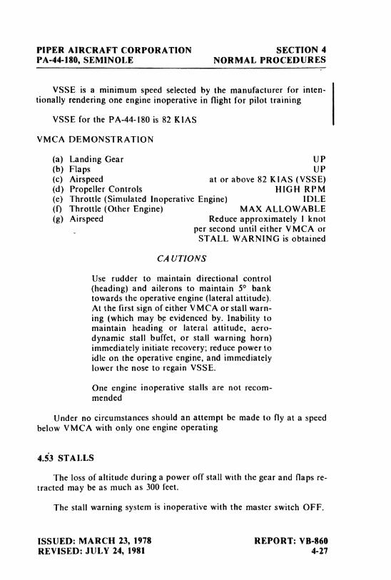
PIPER AIRCRAFT CORPORATION SECTION 4PA-44-180, SEMINOLE NORMAL PROCEDURES
VSSE is a minimum speed selected by the manufacturer for inten-tionally rendering one engine inoperative in flight for pilot training
VSSE for the PA-44-180 is 82 KIAS
VMCA DEMONSTRATION
(a) Landing Gear UP(b) Flaps UP(c) Airspeed at or above 82 KIAS (VSSE)(d) Propeller Controls HIGH RPM(e) Throttle (Simulated Inoperative Engine) IDLE(f) Throttle (Other Engine) MAX ALLOWABLE(g) Airspeed Reduce approximately I knot
per second until either VMCA orSTALL WARNING is obtained
CAUTIONS
Use rudder to maintain directional control(heading)and ailerons to maintain 5° banktowards the operative engine (lateral attitude).At the first sign of either VMCA or stall warn-ing (whichmay be evidenced by. Inability tomaintain heading or lateral attitude, aero-dynamic stall buffet, or stall warning horn)immediately initiate recovery; reduce power toidle on the operative engine, and immediatelylower the nose to regain VSSE.
One engine inoperative stalls are not recom-mended
Under no circumstances should an attempt be made to fly at a speedbelow VMCA with only one engine operating
4.53 STALLS
The loss of altitude during a power off stall with the gear and flaps re-tracted may be as much as 300 feet.
The stall warning system is inoperative with the master switch OFF.
ISSUED: MARCH 23, 1978 REPORT: VB-860REVISED: JULY 24, 1981 4-27

TABLE OF CONTENTS
SECTION 5
PERFORMANCE
Paragraph PageNo. No.
5.1 General .......................................... 5-15.3 Introduction - Performance and Flight Planning ....... 5-155 Flight Planning Example ........................... 5-35.7 Performance Graphs ............................... 5-9
List of Figures .................................. 5-9
REPORT: VB-8605-i

PIPER AIRCRAFT CORPORATION SECTION 5PA-44-180, SEMINOLE PERFORMANCE
SECTION 5
PERFORMANCE
5.1 GENERAL
All of the required (FAA regulations) and complementary performanceinformation applicable to this aircraft is provided by this section.
Performance information associated with those optional systems andequipment which require handbook supplements is provided by Section 9(Supplements).
All data given is for both two and three blade propellers unless other-wise noted.
5.3 INTRODUCTION - PERFORMANCE AND FLIGHT PLANNING
The performance information presented in this section is based onmeasured Flight Test Data corrected to I.C.A.O. standard day conditionsand analytically expanded for the various parameters of weight, altitude,temperature, etc.
The performance charts are unfactored and do not make any allowancefor varying degrees of pilot proficiency or mechanical deterioration of theaircraft. This performance, however, can be duplicated by following thestated procedures in a properly maintained airplane.
Effects of conditions not considered on the charts must be evaluated bythe pilot, such as the effect of soft or grass runway surface on takeoff andlanding performance, or the effect of winds aloft on cruise and rangeperformance. Endurance can be grossly affected ov improper leaningprocedures, and inflight fuel flow and quantity checks are recommended.
REMEMBER! To get chart performance, follow the chart procedures.
ISSUED: MARCH 23, 1978 REPORT: VB-860REVISED: DECEMBER 15, 1978 5-1
SECTION 5 PIPER AIRCRAFT CORPORATIONPERFORMANCE PA-44-180, SEMINOLE
The information provided by paragraph 5.5 (Flight Planhing Example)outlines a detailed flight plan using the performance charts in this section.Each chart includes its own example to show how it is used.
WARNING
Performance information derived by extrapo-lation beyond the limits shown on the chartsshould not be used for flight planningpurposes.
REPORT: VB-860 ISSUED: MARCH 23, 19785-2 REVISED: SEPTEMBER 14, 1979
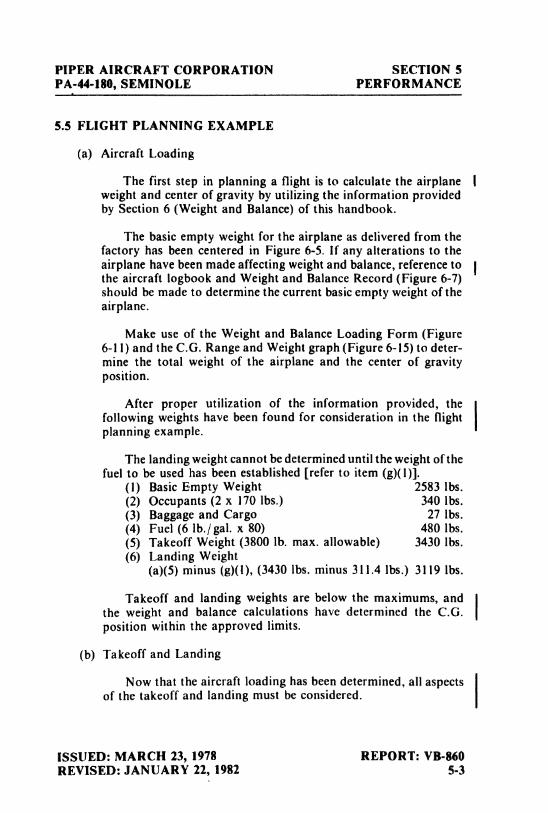
PIPER AIRCRAFT CORPORATION SECTION 5PA-44-180, SEMINOLE PERFORMANCE
5.5 FLIGHT PLANNING EXAMPLE
(a) Aircraft Loading
The first step in planning a flight is to calculate the airplane Iweight and center of gravity by utilizing the information providedby Section 6 (Weight and Balance) of this handbook.
The basic empty weight for the airplane as delivered from thefactory has been centered in Figure 6-5. If any alterations to theairplane have been made affecting weight and balance, reference tothe aircraft logbook and Weight and Balance Record (Figure 6-7)should be made to determine the current basic empty weight of theairplane.
Make use of the Weight and Balance Loading Form (Figure6-1I) and the C.G. Range and Weight graph (Figure 6-15) to deter-mine the total weight of the airplane and the center of gravityposition.
After proper utilization of the information provided, thefollowing weights have been found for consideration in the flightplanning example.
The landing weight cannot be determined until the weight of thefuel to be used has been established [referto item (g)(l)].
(1) Basic Empty Weight 2583 lbs.(2) Occupants (2 x 170 lbs.) 340 lbs.(3) Baggage and Cargo 27 lbs.(4) Fuel (6 lb./ gal. x 80) 480 lbs.(5) Takeoff Weight (3800lb. max. allowable) 3430 lbs.(6) Landing Weight
(a)(5)minus (g)(1),(3430lbs. minus 311.4 lbs.) 3119 lbs.
Takeoff and landing weights are below the maximums, andthe weight and balance calculations have determined the C.G.position within the approved limits.
(b) Takeoff and Landing
Now that the aircraft loading has been determined, all aspectsof the takeoff and landing must be considered.
ISSUED: MARCH 23, 1978 REPORT: VB-860REVISED: JANUARY 22, 1982 5-3
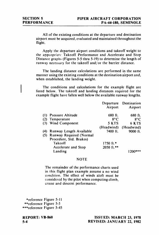
SECTION 5 PIPER AIRCRAFT CORPORATIONPERFORMANCE PA-44-180, SEMINOLE
All of the existing conditions at the departure and destinationairport must be acquired, evaluated and maintained throughout theflight.
Apply the departure airport conditions and takeoff weight tothe apptopriate Takeoff Performance and Accelerate and StopDistance graphs (Figures 5-5 thru 5-19) to determine the length ofrunway necessary for the takeoff and/or the barrier distance.
The landing distance calculations are performed in the samemanner using the existing conditions at the destination airport and,when established, the landing weight.
The conditions and calculations for the example flight arei listed below. The takeoff and landing distances required for the
example flight have fallen well below the available runway lengths.
Departure DestinationAirport Airport
(I) Pressure Altitude 680 ft. 680 ft.(2) Temperature 8°C 8°C(3) Wind Component 5 KTS 6 KTS
(Headwind) (Headwind)(4) Runway Length Available 7400 ft. 9000 ft,(5) Runway Required (Normal
Procedure, Std. Brakes)Takeoff 1750 ft.*Accelerate and Stop 2050 ft.**Landing 1200***
NOTE
The remainder of the performance charts usedin this flight plan example assume a no windcondition. The effect of winds aloft must beconsider ed by the pilot when computing climb,cruise and descent performance.
*reference Figure 5-11**reference Figure 5-5
***reference Figure 5-45
REPORT: VB-860 ISSUED: MARCH 23, 19785-4 REVISED: JANUARY 22, 1982
PIPER AIRCRAFT CORPORATION SECTION 5PA-44-180, SEMINOLE PERFORMANCE
(c) Climb
The next step in the flight plan is to determine the necessaryclimb segment components.
The desired cruise pressure altitude and cotresponding cruiseoutside air temperature values are the fiist variables to beconsidered in determining the climb components from the Fuel,Time and Distance to Climb graph (Figure 5-27). After the fuel,time and distance for the cruise pressure altitude and outside airtemperature values have been established, apply the existingconditions at the departure field to graph (Figure 5-27). Now,subtract the values obtained from the graph for the field ofdeparture conditions from those for the cruise pressure altitude.
The remaining values are the true fuel, time and distancecomponents for the climb segment of the flight plan corrected forfield pressure altitude and temperature.
The following values were determined from the aboveinstructions in the flight planning example.
(1) Cruise Pressure Altitude 5500 ft.(2) Cruise OAT -2°C(3) Time to Climb (4.5 min. minus I.2 min.) 3.3 min.*(4) Distance to Climb (7 naut. miles
minus I.4 naut. miles) 5.6 naut. miles*(5) Fuel to Climb (2.5 gal. minus 1.0 gal.) 1.5 gal.*
(d) Descent
The descent data will be determined prior to the cruise data toprovide the descent distance for establishing the total cruisedistance.
Utilizing the cruise pressure altitude and OAT determine thebasic fuel, time and distance for descent (Figure 5-41) These figuresmust be adjusted for the field pressure altitude and temperature atthe destination airport. To find the necessaly adjustment values,use the existing pressure altitude and temperature conditions at thedestination airport as variables to find the fuel, time and distance
*reference Figure 5-27
ISSUED: MARCH 23, 1978 REPORT: VB-860REVISED: JANUARY 22, 1982 5-5
SECTION 5 PIPER AIRCRAFT CORPORATIONPERFORMANCE PA-44-180, SEMINOLE
values from the graph (Figure 5-41). Now, subtract the valuesobtained from the field conditions from the values obtained fromthe cruise conditions to find the true fuel, time and distance valuesneeded for the flight plan.
The values obtained by proper utilization of the graphs for thedescent segment of the example are shown below.
(I) Time to Descend(9 min. minus 2 min.) 7 min.*
(2) Distance to Descend(30 naut. miles minus4 naut, miles) 26 naut. miles*
(3) Fuel to Descend(3 gal. minus 1 gal.) 2 gal.*
(e) Cruise
Using the total distance to be traveled during the flight, subtractthe previously calculated disiance to climb and distance to descendto establish the total cruise distance. Refer to the appropriateLycoming Operator's Manual and the Power Setting Tables whenselecting the cruise power setting. The established pressure altitudeand temperature values and the selected cruise power should now beutilized to determine the true airspeed from the Speed Power graph(Figure 5-31).
Calculate the cruise fuel for the cruise power setting from theinformation provided on Figure 5-31.
The cruise time is found by dividing the cruise distance by thecruise speed and the cruise fuel is found by multiplying the cruisefuel flow by the cruise time.
The cruise calculations established for the cruise segment ofthe flight planning example are as follows:
(1) Totai Distance 394 miles(2) Cruise Distance
(e)(I) minus (c)(4)minus (d)(2),(394naut. miles minus 5.6 naut.miles minus 26 naut. miles) 362.4 naut. miles
*reference Figure 5-4I
REPORT: VB-860 ISSUED: MARCH 23, 19785-6 REVISED: JANUARY 22, 1982
PIPER AIRCRAFT CORPORATION SECTION 5PA-44-180, SEMINOLE PERFORMANCE
(3) Cruise Power (Best PowerMixture) 55% rated power
(4) Cruise Speed 138 KTS TAS*(5) Cruise Fuel Consumption 18.6 GPH*(6) Cruise Time
(e)(2)divided by (e)(4),(362,4naut.miles divided by 138 KTS) 2.6 hrs.
(7) Cruise Fuel(e)(5)multiplied by (e)(6),(18.6GPH multiplied by 2.6 hrs.) 48.4 gal.
(f) Total Flight Time
The total flight time is determined by adding the time to climb,the time to descend and the cruise time. Remember! The time valuestaken from the climb and descent graphs are in minutes and must beconverted to hours before adding them to the cruise time.
The following flight time is required for the flight planningexample.
(I) Total Flight Time(c)(3)plus (d)(I) plus (e)(6),(0.06hrs. plus
.12
hrs. plus 2.6 hrs.) 2.78 hrs.
(g) Total Fuel Required
Determine the total fuel required by adding the fuel to climb,the fuel to descend and the cruise fuel. When the total fuel (ingallons) is determined, multiply this value by 61b./ gal. to determinethe total fuel weight used for the flight.
The total fuel calculations for the example flight plan areshown below.
(1) Total Fuel Required(c)(5)plus (d)(3)plus (e)(7),(1.5gal. plus 2.0 gal. plus 48.4 gal.) 51.9 gal.(51.9gal. multiplied by 6 1b./gal.) 311.4 lbs.
*reference Figure 5-31
ISSUED: MARCH 23, 1978 REPORT: VB-860REVISED: JANUARY 22, 1982 5-7
SECTION 5 PIPER AIRCRAFT CORPORATIONPERFORMANCE PA-44-180, SEMINOLE
THIS PAGE INTENTIONALLY LEFT BLANK
REPORT: VB-860 ISSUED: MARCH 23, 19785-8
PIPER AIRCRAFT CORPORATION SECTION 5PA-44-180, SEMINOLE PERFORMANCE
5.7 PERFORMANCE GRAPHS
LIST OF FIGURES
Figure PageNo. No.
5-1 Airspeed Calibration ............................... 5-115-3 Stall Speed Vs. Angle of Bank ...................... 5-125-5 Normal Procedure - Accelerate and Stop Distance . . . . . 5-135-7 Short Field Accelerate and Stop Distance............. 5-145-9 Normal Procedure Takeoff Ground Roll (0° Flaps) .... 5-155-11 Normal Procedure Takeoff Distance Over 50 Ft.
. Barrier (0° Flaps)................................ 5-165-13 Short Field Effort Takeoff Ground Roll (0° Flaps). . . . . 5-175-15 Short Field Effort Takeoff Distance Over 50 Ft.
Barrier (0° Flaps)................................ 5-185-17 Short Field Effort Takeoff Ground Roll (25° Flaps). . . . 5-195-19 Short Field Effort Takeoff Distance Over 50 Ft.
Barrier (25° Flaps)............................... 5-205-21 Climb Performance - Both Engines Operating - Gear
Down .......................................... 5-215-23 Climb Performance - Both Engines Operating -
Gear Up........................................ 5-225-25 Climb Performance - One Engine Operating -
Gear Up........................................ 5-235-27 Fuel, Time and Distance to Climb . . . . . . . . . . . . . . . . . . . 5-245-29 Power Setting Table ............................... 5-255-31 Speed Power...................................... 5-265-33 Standard Temperature Performance Cruise Range . . . . . 5-275-35 Standard Temperature Economy Cruise Range . . . . . . . . 5-285-37 Performance Cruise Endurance . . . . . . . . . . . . . . . . . . . . . . 5-295-39 Economy Cruise Endurance......................... 5-305-41 Fuel, Time and Distance to Descend ................. 5-315-43 Landing Ground Roll .............................. 5-325-45 Landing Distance Over 50 Ft. Barrier ................ 5-33
ISSUED: MARCH 23, 1978 REPORT: VB-860REVISED: SEPTEMBER 14, 1979 5-9
SECTION 5 PIPER AIRCRAFT CORPORATIONPERFORMANCE PA-44-180, SEMINOLE
THIS PAGE INTENTIONALLY LEFT BLANK
REPORT: VB-860 ISSUED: MARCH 23, 19785-10
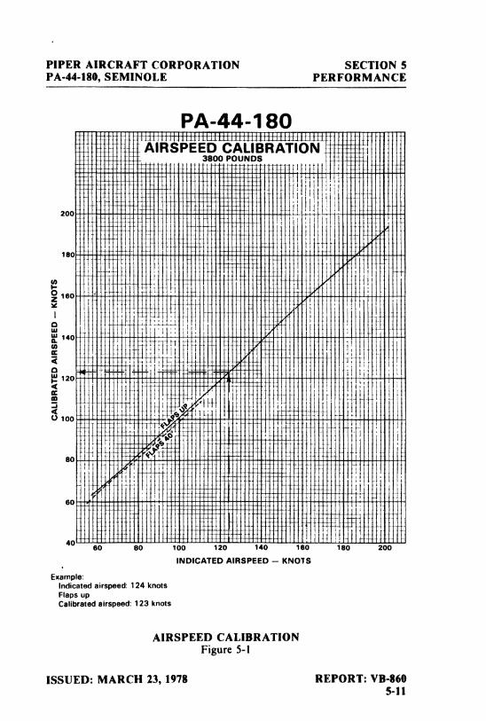
PIPER AIRCRAFT CORPOllATION SECTION 5PA-44-180, SEMINOLE PERFORMANCE
PA-44-1 80ff±tttHfH±ttif ±±1±±± f±f±f±±J±iB±f±AIRSPEEP CL RATION
200 -
180 -
160
140
120
100
ao
60
406C 33 1 m 0 1 tu ¾MO
INDICATED AIRSPEED - KNOTS
Example:Indicated airspeed: 124 knotsFlaps upCalibrated airspeed: 123 knots
AIRSPEED CALIBRATIONFigure 5-1
ISSUED: MARCH 23, 1978 REPORT: VB-8605-11
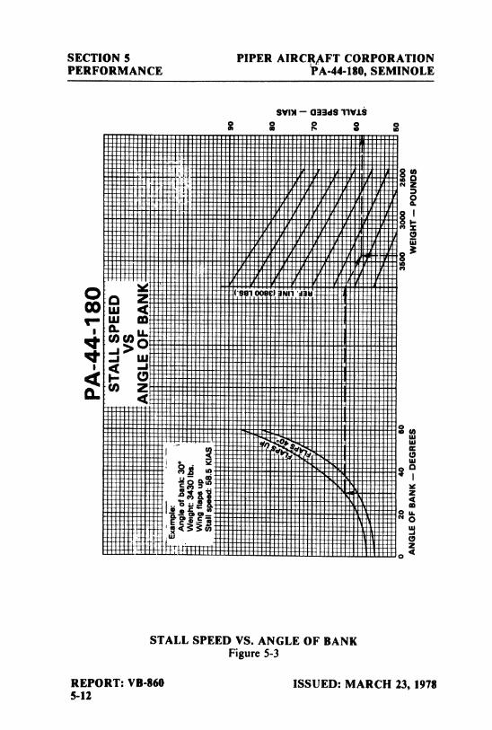
SECTION 5 PIPER AIRCRAFT CORPORATIONPERFORMANCE WA-44-180, SEMINOLE
SVOI - 033dS 11V 18
go
os a
.. w m(L &ww
STALL SPEED VS. ANGLE OF BANKFigure 5-3
REPORT: VB-860 ISSUED: MARCH 23, 19785-12
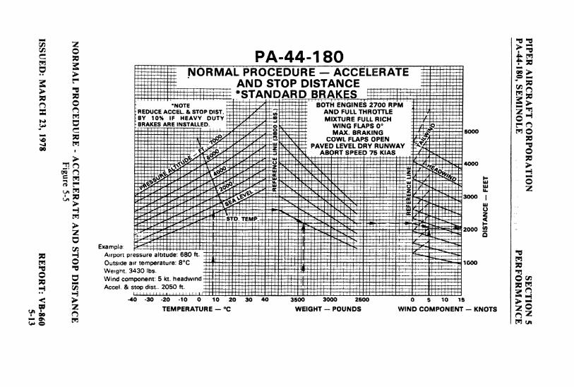
PA-44-180.NORMAL PROCEDURE - ACCELERATE
AND STOP DISTANCE*STANDARD BRAKES
.NOTE BOTÑENGINES 2700 RPREDUCE ACCEL. & STOP DIST. AND FULLTHROTTLEBY 10% IF HEAVY DUTY MIXTURE FULL RICHBRAKES ARE INSTALLED. WING FLAPS 0° t"
MAX. BRAKING 5000 MCOWL FLAPS OPEN
PAVED LEVEL DRY RUNWAYABORT SPEED 75 KIAS
3000
Example
2000
Outside air temperature 8 CWerght. 3430 lbs.Wind component: 5 kt.
.. Accel. & stop dist.. 2050 ft-40 -30 -20 -10
0 10 20 30 40 3500 3000 2500 a e 10 13
TEMPERATURE - C WEIGHT - POUNDS WIND COMPONENT - KNOTS 2on a 2
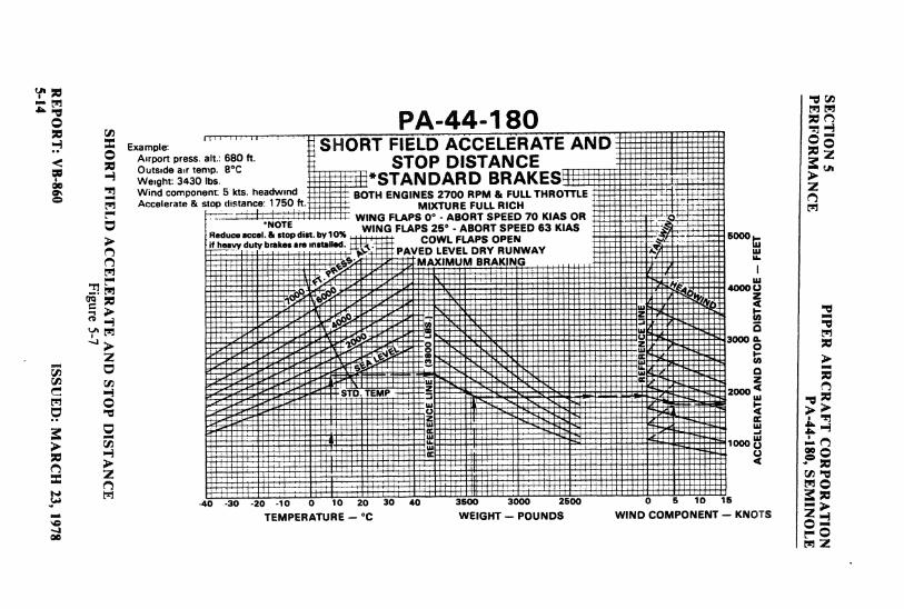
PA-44-180Example: SHORT FIELD ACCELERATEAND
As aen 80 ft. STOP DISTAN CEWeight: 3430 lbs *STANDARD BRAKESWind component 5 kts. headwmd BOTH ENGINES 2700 RPM & FULLTHROTTLEAccelerate & t top distance 1750 ft MIXTURE FULL RICH
WING FLAPS 0° - ABORT SPEED 70 KIAS ORNOTE WING FLAPS 26° - ABORT SPEED 63 KIAS
PAVECDOE
DRSORUWAY
5000
M IMUM BRAK q
STD TEMP 2000
-d
0-30 -20 -10
0 10 20 30 40 3500 3000 2500 0 5 10 16
TEMPERATURE - °C WEIGHT - POUNDS WIND COMPONENT - KNOTS
M 2
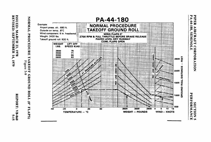
PA-44-180Ex
p press.alt..680ft. NORMAL PROCEbÜREoutsideairtemp..8°C -TAKEOFF GROUND ROLLWind component: 6 kt. headwmd i
' WlÑG FiPS 0°Weight: 3430 lbs- i 2700 RPM & FULLTHROTTLE BEFORE BRAKE RELEASETakeoff ground roll: 920 ft. 4 PAVED LEVEL DRY RUNWAY
COWL FLAPS OPENWEIGHT LIFT OFF
LBS. wrru r
3000 662600 62
2500
2ooo
l' I i .¡oo-40 -20
0 20 40 3600 3000 2500 a 5 10 1 i
TEMPERATURE - *C WElGHT - POUNDS WIND- KNOT I
tsa o M ut
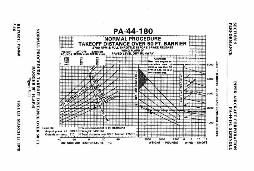
PA-44-180NORMAL PROCEDURE
TAKEOFF DISTANCE OVER 50 FT. BARRIER2700 RPM & FULL THROTTLE BEFORE BRAKE RELEASE
WEIGHT UFT OFF BARRIER WING FLAPS 0*PouNDs SPEED KIAS SPEED KIAS PAVED LEVg DRY RUNgAY
,7 :: H Au3000 66 78 Best one engme m-2000 62 73 rate of 5000
climb is less than 50FPM if T.O. wt. is mthe shaded arms.
3000
zooo
Example: ind component 5 kt. headwindAirport press. alt.: 680 ft. Weight: 3430 lbs.Outside air temp.. 8°C Total distance over 50 ft. barner 1750 ft
-40 -20
0 20 40 3600 3000 2500 ) 5 10 1 i.. OUTSIDE AIR TEMPERATURE - °C WEIGHT - POUNDS WIND-- KNOT3 ...
on o 2
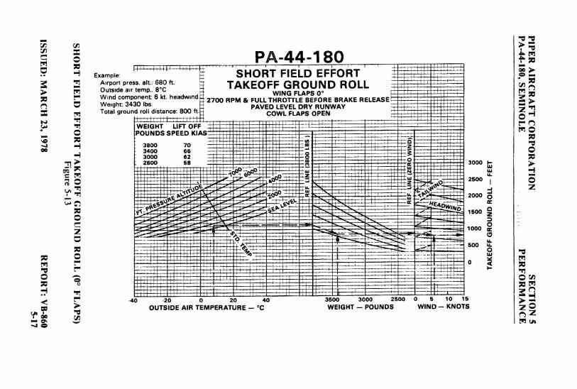
PA-44-180Example: SHORT FIELD EFFORT
' °2" TAKEOFF GROUND ROLLconi n 6 kt. headwind 2700 RPM & FULLT
TTFLF RE BRAKE RELEASE
Total ground roll distance: 800 ft. PAVECDOLWELVELDRSOR WAY
WEIGHT LIFT OFF
aeoo 7o
600 58 3000
2soo
500
-40 -20
0 20 40 3500 3000 2500 1 5 10 15OUTSIDE AIR TEMPERATURE -- °C WEIGHT - POUNDS WIND- KNOTS 2 Q
Y' de a 2
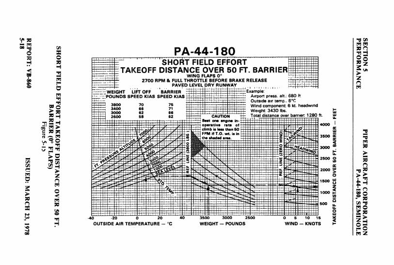
o' E PA-44-180 "-o-SHORT FIELD EFFORTTAKEOFF DISTANCE OVER 50 FT. BARRIER
WING FLAPS 0°2700 RPM & FULL THROTTLE BEFORE BRAKE RELEASE
PAVED LEVEL DRY RUNWAYEIGHT LIR OFF BARRIER ExaÑ\e
POUNDS SPEED KIAS SPEED KIAS Airport press. alt.: 680 ftOutside air temp.. 8°C
3900 70 75 Wind component 6 kt. headwindWeight: 3430 lbs.
2600 58 62 CAUTION Total distance o er barrier 1280 ft.B..t one engme in-
-43 -20
t 20 40 3500 3000 2500 a 5 10 15
OUTSIDE AIR TEMPERATURE - °C WEIGHT - POUNDS WIND - KNOTS
ao gy
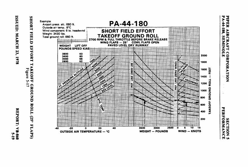
Exr press. alt.: 680 ft. PA-44-1 80Outside air temp.. 8°C
Wind component 6 kt. headwmd SHORT FIELD EFFORT1"oîÛo'Índ0rI 660ft a TAKEOFF GROUND ROLL
2700 RPM & FULLTHROTTLEBEFORE BRAKE RELEASEWING FLAPS - 25° COWL FLAPS OPEN
WEIGHT LIFT OFF PAVED LEVEL DRY RUNWAYPOUNDS SPEED KIAS
3800 633400 SO 2000
sooo se2600 62 1 1800
oooz
800
600
-40 -20
0 20 40 3500 3000 2600 0 5 10 15
OUTSIDE AIR TEMPERATURE - C WEIGHT - POUNDS WIND - KNOTS
e
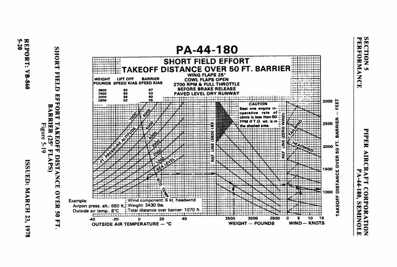
PA-44-180SHORT FIELD EFFORT
TAKEOFF DISTANCE OVER 50 FT. BARRIER.. WING FLAPS 25
WEIGHT LIFT OFF BARRIER COWL FLAPS OPENPOUNDS SPEED KIAS SPEED KIAS 2700 RPM & FULL THROTTLE
3800 63 67 BEFORE BRAKE RELEASEPAVED LEVEL DRY RUNWAY
2600 52 55CAUTION
Best one engine en-operative rate ofclimb is less than 50F area.is in
2500
2000
Example: Wind component 6 kt. headwmdAirport press. alt.: 680 ft Weight 3430 lbs.Outside air temp.. 8°C Total distance over barrier 1070 ft
-40-20
0 20 40 3500 3000 2500 0 5 10 15
OUTSIDE AIR TEMPERATURE - °C WEIGHT -- POUNDS WIND- KNOTS
on 2
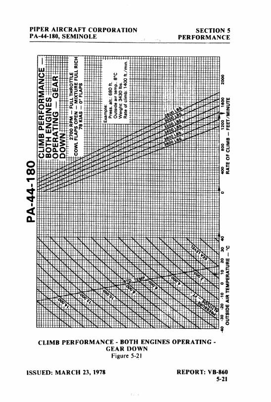
PIPER AIRCRAFT CORPORATION SECTION 5PA-44-180, SEMINOLE PERFORMANCE
Om I 2
w o
42-w>
iDaOOO
00
i
4CL
CLIMB PERFORMANCE - BOTH ENGINES OPERATING -
GEAR DOWNFigure 5-21
ISSUED: MARCH 23, 1978 REPORT: VB-8605-21
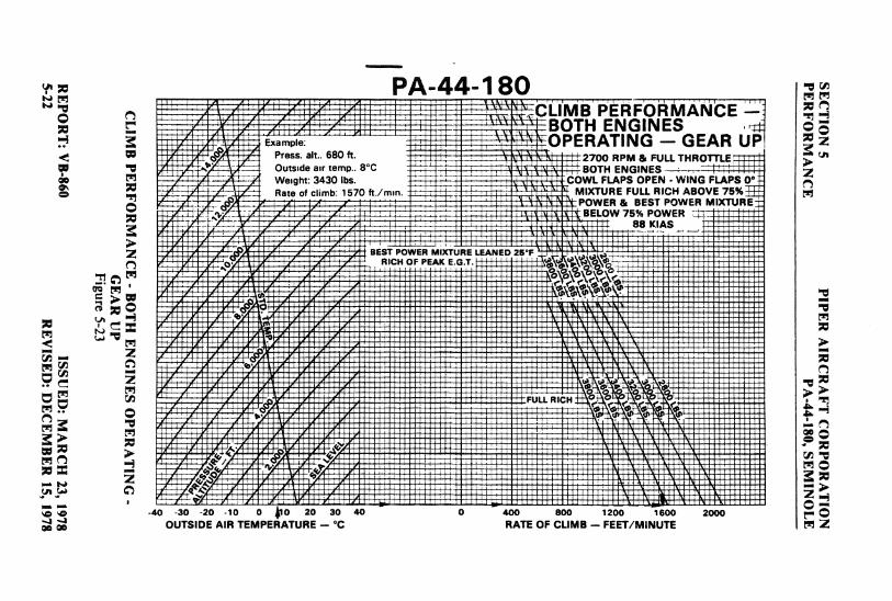
PA-44-180I IIVIN PÈRFOÀWIAÑ'CE --
AEIN GEAR U
Press. alt.. 680 ft huu RPM & FULLTHROTTLEOutside air temp.. 8°C nrtTu ENGINES ,
¯
00 Weight: 3430 lbs. L FLAPS OPEN - WING FLAPS ORate of climb: 1570 ft./m n MIXTURE FULL RICH ABOVE 75%
88 KIAS
BEST POWER MIXTURE LEANED 25 FRICH () EAK E.G.T.
HH
-40 -30 -20 -10
0 0 20 30 40 0 400 800 1200 1600 2000 y ÔOUTSIDE AIR TEMPERATURE -- °C RATE OF CLIMB - FEET/MINUTE N 2
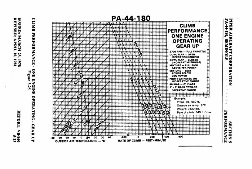
PA-44-180PERFORMANCE
ONE ENGINEOPERATING
GEAR UPIwm - F NOTTLE
(OPERATING ENGINE)cowL FLAP - CLOSED
00 (INOPERATIVE ENGINE)MIXTURE - FULL RICH
ABOVE 75% POWERMIXTURE - BEST
00 POWER BELOW75% POWER
PROÞ FEATHERED ONINOPERATIVE ENGINE
88 KIAS - O' FLAPS3° - S' BANK TOWARD
OPERATIVE ENGINE
Example:Press alt.. 680 ft
Outside air temp 8°C
a cm3b 3b
ft./mm
-4) -30 -2o
-1õ
0 0 20 so 40-200
o 200 40 000
OUTSIDE AIN TEMPERATURE - °C RATE OF C1.IMB - FEET/MINUTE .
A ut
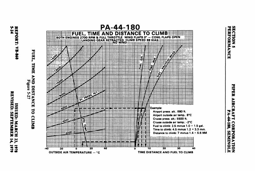
:: PA-44-1 80 gg¡FUEL, TIME AND DISTANCE TO CUMB
BOTH ENGINES 2700 RPM & FULL THROTTLE WING FLAPS 0° - COWL FLAPS OPENLANDING GEAR RETRACTED CLIMB SPEED 88 KIAS
NO WIND
.o* Example:Airport press alt . 680 ft.Airport outside air temp.. 8°C
4000 Cruise press. alt.: 5500 ft.Cruise outside air temp.: -2°CFuel to climb: 2.5 mmus 1.0 = 1.5 gal.Time to climb: 4.5 mmus 1.2 = 3.3 mm.
ooo Distance to climb: 7 mmus 1.4 = 5.6 NM
40 20 0 20 40 0 10 20 30 40
OUTSIDE AIR TEMPERATURE -°C TIME DISTANCE AND FUEL TO CLIMB
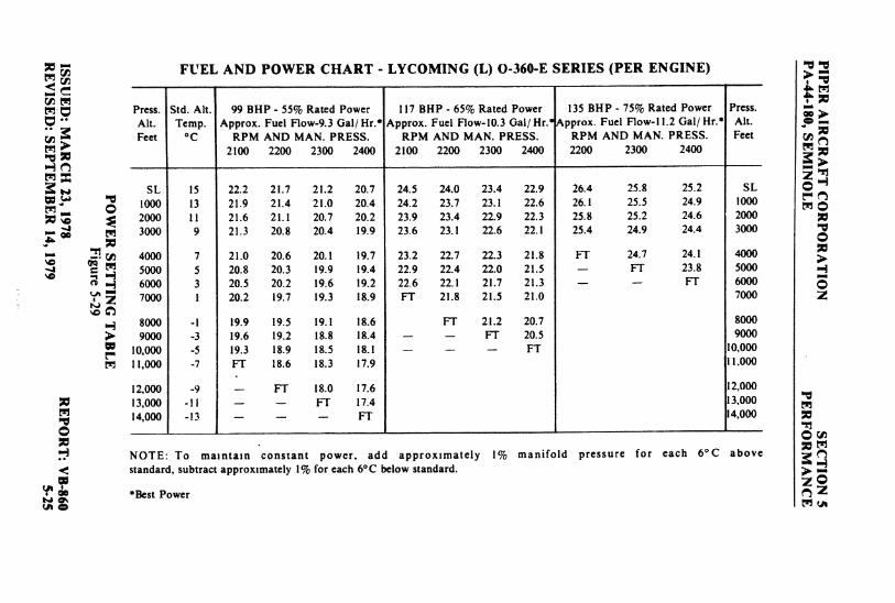
FUEL AND POWER CHART - LYCOMING (L) O-360-E SERIES (PER ENGINE) N 2
Press. Std. Alt. 99 BHP - 55% Rated Power 117 BHP - 65% Rated Power 135 BHP - 75% Rated Power Press.Alt. Temp. Approx. Fuel Flow-9.3 Gal/ Hr.* Approx. Fuel Flow-10.3 Gal/ Hr.* Approx. Fuel Flow-ll.2 Gal/ Hr.* Alt.Feet °C RPM AND MAN. PRESS. RPM AND MAN. PRESS. RPM AND MAN. PRESS. Feet
2100 2200 2300 2400 2100 2200 2300 2400 2200 2300 2400
SL 15 22.2 21.7 21.2 20.7 24.5 24.0 23.4 22.9 26.4 25.8 25.2 SL1000 13 21.9 21.4 21.0 20.4 24.2 23.7 23.1 22.6 26.1 25.5 24.9 10002000 11 21.6 21.1 20.7 20.2 23.9 23.4 22.9 22.3 25.8 25.2 24.6 20003000 9 21.3 20.8 20.4 19.9 23.6 23.1 22.6 22.1 25.4 24.9 24.4 3000
4000 7 21.0 20.6 20.1 19.7 23.2 22.7 22.3 21.8 FT 24.7 24.1 40005000 5 20.8 20.3 19.9 19.4 22.9 22.4 22.0 21.5 - FT 23.8 50006000 3 20.5 20.2 19.6 19.2 22 6 22.1 21.7 21.3 - - FT 60007000 1 20.2 19.7 19.3 18.9 FT 21.8 21.5 21.0 7000 2
8000-l
19.9 19.5 19.l 18.6 FT 21.2 20.7 80009000
-3
19.6 19.2 18.8 18.4 - - FT 20.5 900010,000
-5
19.3 18.9 18.5 18.1 - - - FT 10,000
m 11,000-7
FT 18.6 18.3 17.9 11,000
12,000-9
- FT 18.0 17.6 12,00013,000
-11
- - FT I7.4 13,00014,000
-13
- - - FT 14,000
NOTE: To maintain constant power, add approximately 1% manifold pressure for each 6°C abovestandard, subtract approximately 1% for each 6°C below standard.
m *Best Power 2
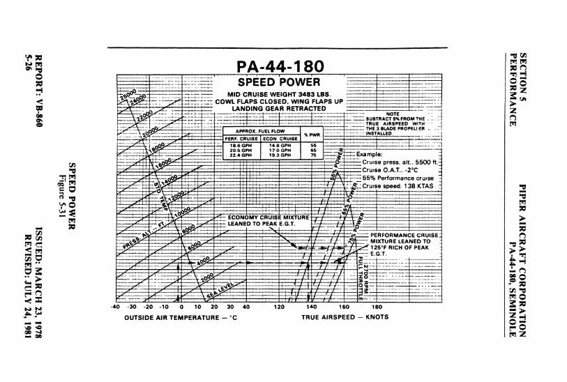
à ", PA-44-1 80SPEED POWER
- MID CRUISE WEIGHT 3483 LBS.COWL FLAPS CLOSED, WING FLAPS UP
LANDING GEAR RETRACTEDtiiRTRAtyTO
TRUE AIRSPEED W TH
PER
ALPPROX FUEECLFLOCWRutSE% PWR
SE3 B DDEPROPELI ER
18 6 GPH 14 8 GPH 5520 5 GPH 17 O GPH 6522 4 GPH 19 3 GPH 75 --
xaFT1ple;
r,ta 3 : p Laa. alt.. 5500 ftPrinen r3 A T -2°C
MIXTURE LEANED TO
-40 -30 -20 -10
0 10 20 30 40 120 140 160 180
OUTSIDE AIR TEMPERATURE - °C TRUE AIRSPEED - KNOTS
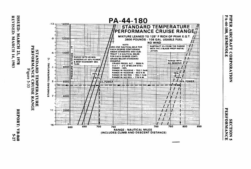
PA-44-180STANDARD TEMPERATUREN
Pt·HeuRMANCE CRUISE RANGEgMIXTURE LEANED TO 125° F RICH OF PEAK E.G.T.
3800 POUNDS 1008WGAOLUSABLE FUEL
HODG
EOR U ROMHOH
ABOVE STANDARD AND SUB- 1.AT10N
N T FC
AECE
ENI S
EBS
EECAON55M O R AAM LOW STANDARD.RANGE H
on CHUISE PRESS. ALT. = 5500 ft N RESERVE
- ooo°,^j; C (6 BELOW STD.)
RANGE W/RESERVE = 702 (1.3RANGE W/RESERVE = 693 N.M 75
- 3 - eoot re cr.
g og 650 700 750 700 750 800 8 0RANGE - NAUTICAL MILES
(INCLUDES CLIMB AND DESCENT DISTANCE)
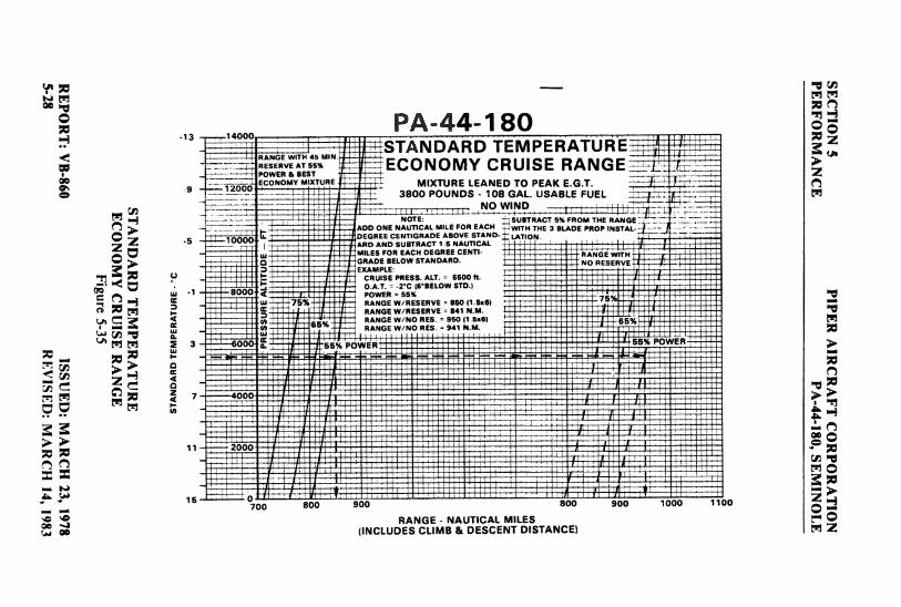
PA-44-180SIANDARD TEMPERATURE
<' RANGE WITH 45 MIN
nu HESERVEAT65% ECONOMY CRUISE RANGEe POWER & BEST
ECONOMY MIXTURE : MIXTURE LEANED TO PEAK E.G.T.3800 POUNDS - 108 GAL. USABLE FUEL
,NO WINDNOTE: SUBTRACT 5% FROM THE RANGE
ADD ONE NAUTICAL MILE FOR EACH WITH THE 3 BLADE PROP INSTAL
& 3000 DEGREE CENTIGRADE ABOVE STAND. LATIONARD AND SUBTRACT 1.5 NAUTICALMILES FOR EACH DEGREE CENTI- RANGE WITHGRADE BELOW STANDARD. NO RESERVEEXAMPLE:
CRUISE PRESS. ALT. = 5500 ft-1
8000O.A.T. =
-2
C (6°BELOW STD.)POWER = 55%
75% RANGE W/RESERVE = 860 (1.5x6)RANGE W/RESERVE = 841 N.M.
65% RANGE W/NO RES. = 950 (1 Ex6)
3 000 55% Pf
7 10 800 900 800 900 1000 11 10
RANGE - NAUTICAL MILES00 (INCLUDES CLIMB & DESCENT DISTANCE) M 2
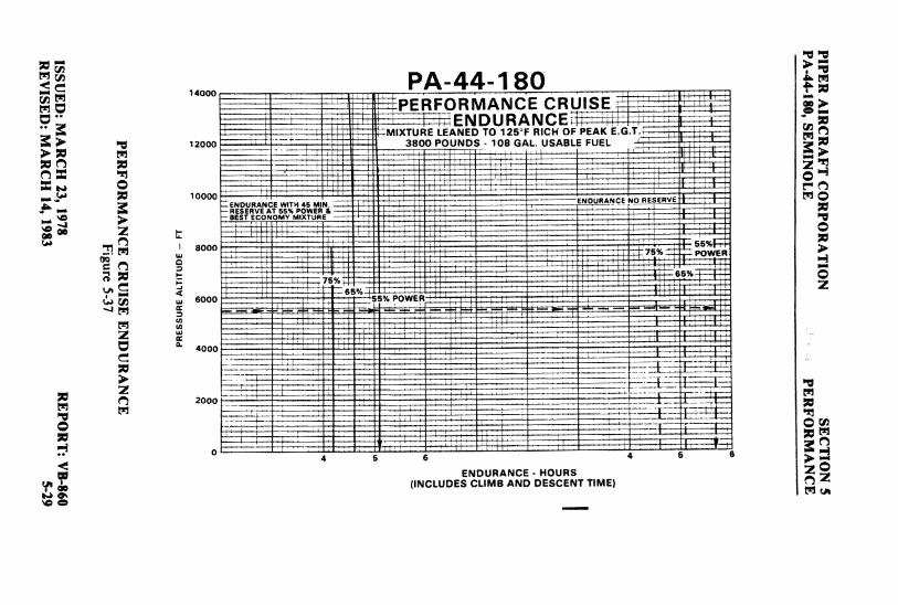
PA-44-180PERFORMANCE CRUISE
ENDURANCE t=TunE LEANED TO 125°F RICH OF PEAK E.G.T.12000 3800 POUNDS - 108 GAL. USABLE FUEL
ccoo ENDURANCE NO RESE
BEST EC NOMY MtKTUS
6000
sooo
4 5 6 4 5
ENDURANCE - HOURS(INCLUDES CLIMB AND DESCENT TIME)
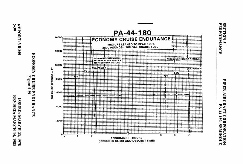
PA-44-180ECOÑOMY'CRUISE ENDURÅNCE
MIXTURE LEANED TO PEAK E.G.T.
,3ß00 POUNDS 108 GAL. USABLE FUEL
D RÀ E H 4 N
416 567ENDURANCE - HOURS
(INCLUDES CLIMB AND DESCENT TIME)
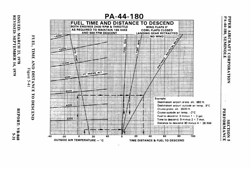
PA-44-180FUEL, TIME AND DISTANCE TO DESCENDBOTH ENGINES 2400 RPM & THROTTLE WING FLAPS 0°AS REQUIRED TO MAINTAIN 165 KIAS COWL FLAPS CLOSED
AND 503 FPM DESCENT LANDING GEAR RETRACTED
Destination airport press alt.. 680 fr.Destination airport outside air temp-. 8°CCruise press. alt.. 5500 ft.Cruise outside air temo.. -2°CFuel to descend: 3 mmus 1 = 2 gal.Time to descend: 9 mmus 2 = 7 mm.Distance to descend 30 mmus 4 = 26 NM
-40 -20
0 20 40 0 2o 40 so 80 100
OUTSIDE AIR TEMPERATURE - °C TIME DISTANCE & FUEL TO DESCEND
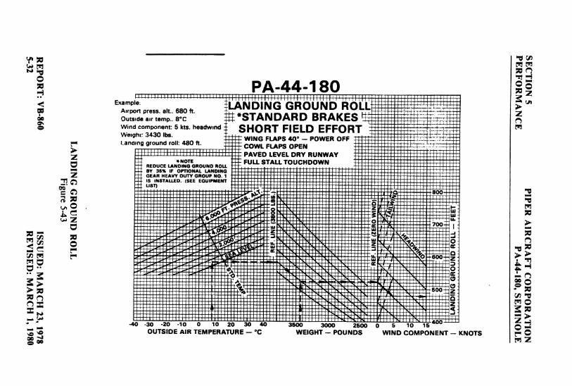
PA-44-180Exam e
TARRDO KROL
: Wind component: 5 kts. headwind SHORT FIELD EFFORTWeighr: 3430 lbs.WING FLAPS 40* - POWER OFFLanaang ground roll: 480 ft. COWL FLAPS OPENPAVED LEVEL DRY RUNWAY
*NOTE FULL STALL TOUCHOOWNREDUCE LANDING GROUND ROLLBY 35% IF OPTIONAL LANDINGGEAR HEAVY DUTY GROUP NO. 1IS INSTALLED. (SEE EOUIPMENT
-· ust;A;. .. 800
600 z
O-30 -20 -10
0 10 20 30 40 3500 3000 2500 0 5 10 15 ...
OUTSIDE AIR TEMPERATURE - °C WEIGHT - POUNDS WIND COMPONENT - KNOTS
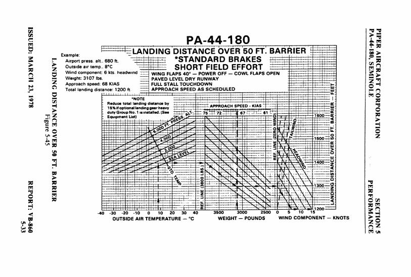
PA-44-180Example:
LANDING'DISTANCE ÒVER'50 FT. BANÁlERe Airport press. alt.. 680 ft. | \ -, *STANDARD BRAKES
Outside air temp.. 8·c SHORT FIELD EFFORTWind component: 6 kts. headwind WING FLAPS 40° - POWER OFF - COWL FLAPS OPENWeight: 3107 Ibs PAVED LEVEL DRY RUNWAYApproach speed; 68 KIAS FULL STALL TOUCHDOWNTotal landing distance: 1200 ft. APPROACH SPEED AS SCHEDULED
•NOTE
i pt a aAPP OACH SPEED - KIA
G t)1 smstalled.(See 75¾72 6
-40 -30 -20 -10
0 10 20 30 40 3500 3000 2500 0 5 10 15
OUTSIDE AIR TEMPERATURE -°C WEIGHT - POUNDS WIND COMPONENT - KNOTS

TABLE OF CONTENTS
SECTION 6
WEIGHT AND BALANCE
Paragraph PageNo. No.
6.1 General .......................................... 6-16.3 Airplane Weighing Procedure . . . . . . . . . . . . . . . . . . . . . . . 6-26.5 Weight and Balance Data and Record................ 6-56.7 Weight and Balance Determination for Flight . . . . . . . . . 6-96.9 Instructions for Using the Weight and Balance Plotter.. 6-13
REPORT: VB-8606-1

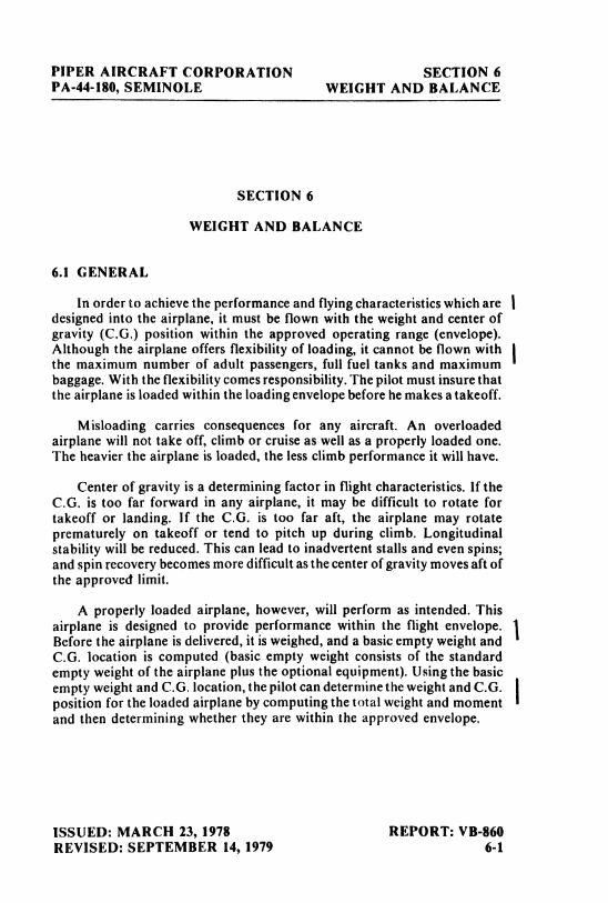
PIPER AIRCRAFT CORPORATION SECTION 6PA-44-180, SEMINOLE WEIGHT AND BALANCE
SECTION 6
WEIGHT AND BALANCE
6.1 GENERAL
In order to achieve the performance and flying characteristics which aredesigned into the airplane, it must be flown with the weight and center ofgravity (C.G.) position within the approved operating range (envelope).Although the airplane offers flexibility of loading, it cannot be flown withthe maximum number of adult passengers, full fuel tanks and maximumbaggage. With the flexibility comes responsibility. The pilot must insure thatthe airplane is loaded within the loading envelope before he makes a takeoff.
Misloading carries consequences for any aircraft. An overloadedairplane will not take off, climb or cruise as well as a properly loaded one.The heavier the airplane is loaded, the less climb performance it will have.
Center of gravity is a determining factor in flight characteristics. If theC.G. is too far forward in any airplane, it may be difficult to rotate fortakeoff or landing. If the C.G. is too far aft, the airplane may rotateprematurely on takeoff or tend to pitch up during climb. Longitudinalstability will be reduced. This can lead to inadvertent stalls and even spins;and spin recovery becomes more difficult as the center of gravity moves aft ofthe approved limit.
A properly loaded airplane, however, will perform as intended. Thisairplane is designed to provide performance within the flight envelope.Before the airplane is delivered, it is weighed, and a basic empty weight andC.G. location is computed (basic empty weight consists of the standardempty weight of the airplane plus the optional equipment). Using the basicempty weight and C.G. location, the pilot can determine the weight and C.G.position for the loaded airplane by computing the total weight and momentand then determining whether they are within the approved envelope.
ISSUED: MARCH 23, 1978 REPORT: VB-860REVISED: SEPTEMBER 14, 1979 6-1
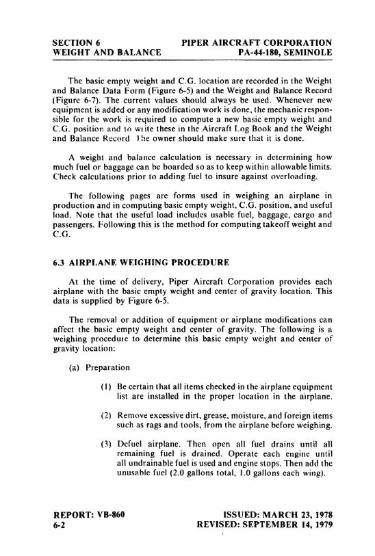
SECTION 6 PIPER AIRCRAFT CORPORATIONWEIGHT AND BALANCE PA-44-180, SEMINOLE
The basic empty weight and C.G. location are recorded in the Weightand Balance Data Form (Figure 6-5) and the Weight and Balance Record(Figure 6-7). The current values should always be used. Whenever newequipment is added or any modification work is done, the mechanic respon-sible for the work is required to compute a new basic empty weight andC.G. position and to wiite these in the Aircraft Log Book and the Weightand Balance Record 1he owner should make sure that it is done.
A weight and balance calculation is necessary in determining howmuch fuel or baggage can be boarded so as to keep within allowable limits.Check calculations prior to adding fuel to insure against overloading.
The following pages are forms used in weighing an airplane inproduction and in computing basic empty weight, C.G. position, and usefulload. Note that the useful load includes usable fuel, baggage, cargo andpassengers. Following this is the method for computing takeoff weight andC.G.
6.3 AIRPLANE WEIGHING PROCEDURE
At the time of delivery, Piper Aircraft Corporation provides eachairplane with the basic empty weight and center of gravity location. Thisdata is supplied by Figure 6-5.
The removal or addition of equipment or airplane modifications canaffect the basic empty weight and center of gravity. The following is aweighing procedute to determine this basic empty weight and center ofgravity location:
(a) Preparation
(1) Be certain that all items checked in the airplane equipmentlist are installed in the proper location in the airplane.
(2) Remove excessive dirt, grease, moisture, and foreign itemssuch as rags and tools, from the airplane before weighing.
(3) Defuel airplane. Then open all fuel drains until allremaining fuel is drained. Operate each engine untilall undrainable fuel is used and engine stops. Then add theunusable fuel (2.0gallons total, I.0 gallons each wing).
REPORT: VB-860 ISSUED: MARCH 23, 19786-2 REVISED: SEPTEMBER 14, 1979
PIPER AIRCRAFT CORPORATION SECTION 6PA-44-180, SEMINOLE WEIGHT AND BALANCE
CAUTION
Whenever the fuel system iscompletely drainedand fuelisreplenished it will be necessary to runthe engines for a minimum of 3 minutes at 1000RPM on each tank to insure no air exists in thefuel supply lines.
(4) Fill with oil to full capacity.
(5) Place pilot and copilot seats in fourth (4th) notch, aft offorward position. Put flaps in the fully retracted positionand all control surfaces in the neutral position. Tow barshould be in the proper location and entrance and baggagedoor closed.
(6) Weigh the airplane inside a closed building to preventerrors in scale readings due to wind.
(b) Leveling
(1) With airplane on scales, block main gear oleo pistons in thefully extended position.
(2) Level airplane (refer to Figure 6-3) deflating nose wheeltire, to center bubble on level.
(c) Weighing - Airplane Basic Empty Weight
(1) With the airplane level and brakes released, record theweight shown on each scale. Deduct the tare, if any, fromeach reading.
ISSUED: MARCH 23, 1978 REPORT: VB-860REVISED: SEPTEMBER 14, 1979 6-3
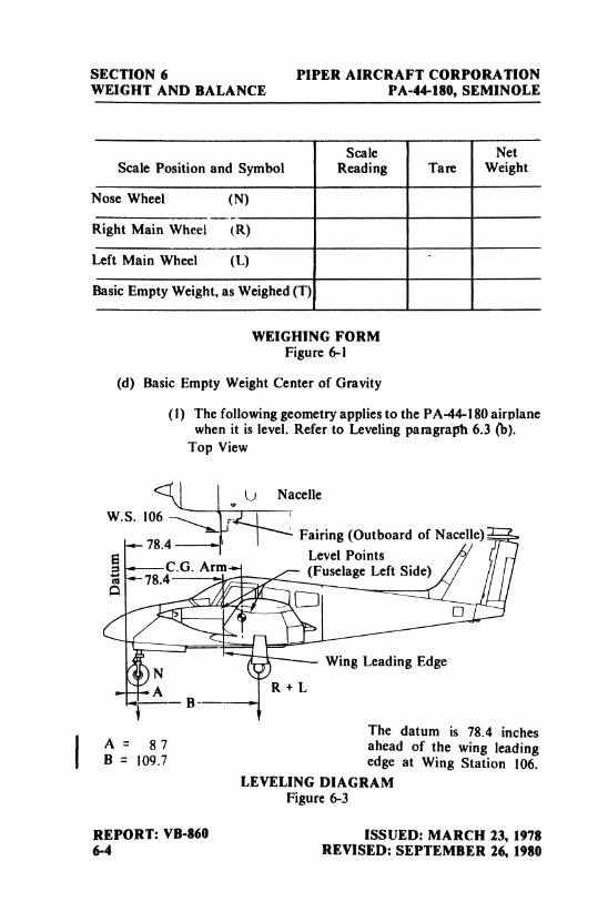
SECTION 6 PIPER AIRCRAFT CORPORATIONWEIGHT AND BALANCE PA-44-180, SEMINOLE
Scale NetScale Position and Symbol Reading Tare Weight
Nose Wheel (N)
Right Main Wheel (R)
Left Main Wheel (L)
Basic Empty Weight, as Weighed (T)
WEIGHING FORMFigure 6-1
(d) Basic Empty Weight Center of Gravity
(1) The following geometry applies to the PA-44-180 airplanewhen it is level. Refer to Leveling pamgraph 6.3 (b).
Top View
Nacelle
W.S 106.4Fairing (Outboard of Nacelle)
Level Points4C.G. Arm (Fuselage Left Side)
O
NWing Leading Edge
- A R + LB-
The datum is 78.4 inches
I A = 8 7 ahead of the wing leadingB = 109.7 edge at Wing Station 106.
LEVELING DIAGRAMFigure 6-3
REPORT: VB-860 ISSUED: MARCH 23, 19786-4 REVISED: SEPTEMBER 26, 1980
PIPER AIRCRAFT CORPORATION SECTION 6PA-4†l80, SEMINOLE WEIGHT AND BALANCE
(2) The basic empty weight center of gravity (as weighedincluding optional equipment, full oil and unusable fuel)can be determined by the following formula:
C.G. Arm = N (A) + (R + L) (B) inchesT
Where: T = N + R + L
6.5 WEIGHT AND BALANCE DATA AND RECORD
The Basic Empty Weight, Center of Gravity Location and Useful Loadlisted in Figure 6-5 are for the airplane as delivered from the factory. Thesefigures apply only to the specific airplane serial number and registrationnumber shown.
The basic empty weight of the airplane as delivered from the factory hasbeen entered in the Weight and Balance Record (Figure 6-7). This form isprovided to present the current status of the airplane basic empty weightand a complete history of previous modifications. Any change to thepermanently installed equipment or modification which affects weight ormoment must be entered in the Weight and Balance Record.
ISSUED: MARCH 23, 1978 REPORT: VB-860REVISED: SEPTEMBER 14, 1979 6-5
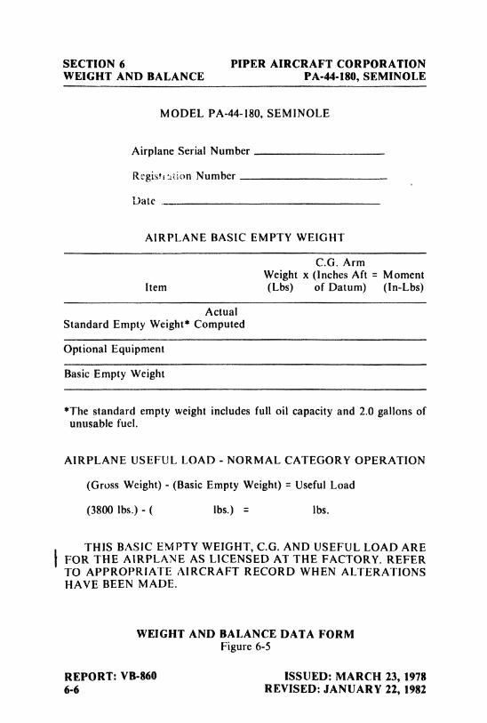
SECTION 6 PIPER AIRCRAFT CORPORATIONWEIGHT AND BALANCE PA-44-180, SEMINOLE
MODEL PA-44-180, SEMINOLE
Airplane Serial Number
Regisetion Number
Date
AIRPLANE BASIC EMPTY WEIGHT
C.G. ArmWeight x (lnchesAft = Moment
Item (Lbs) of Datum) (In-Lbs)
ActualStandard Empty Weight* Computed
Optional Equipment
Basic Empty Weight
*The standard empty weight includes full oil capacity and 2.0 gallons ofunusable fuel.
AIRPLANE USEFUL LOAD - NORMAL CATEGORY OPERATION
(Gross Weight) - (Basic Empty Weight) = Useful Load
(3800lbs.) - ( lbs.) = lbs.
THIS BASIC EMPTY WEIGHT, C.G. AND USEFUL LOAD AREFOR THE AIRPLANE AS LICENSED AT THE FACTORY. REFERTO APPROPRIATE AIRCRAFT RECORD WHEN ALTERATIONSHAVE BEEN MADE.
WEIGHT AND BALANCE DATA FORMFigure 6-5
REPORT: VB-860 ISSUED: MARCH 23, 19786-6 REVISED: JANUARY 22, 1982
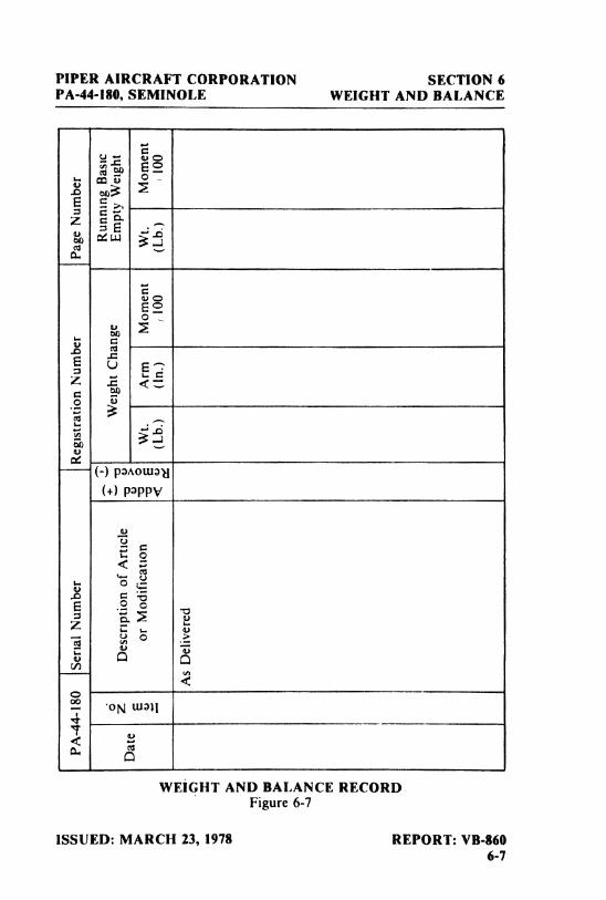
PIPER AIRCRAFT CORPORATION SECTION 6PA-44-180, SEMINOLE WEIGHT AND BALANCE
o ,
o o
WEIGHT AND BALANCE RECORDFigure 6-7
ISSUED: MARCH 23, 1978 REPORT: VB-8606-7
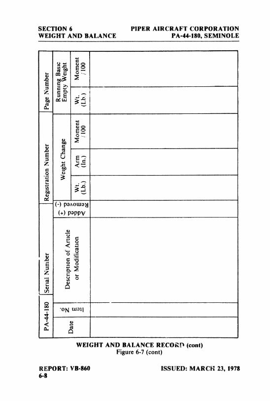
SECTION 6 PIPER AIRCRAFT CORPORATIONWEIGHT AND BALANCE PA-44-180, SEMINOLE
.O Cpg oo
WEIGHT AND BALANCE RECORD (cont)Figure 6-7 (cont)
REPORT: VB-860 ISSUED: MARCH 23, 19786-8
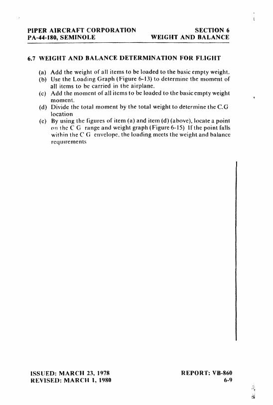
PIPER AIRCRAFT CORPORATION SECTION 6PA-44-180, SEMINOLE WEIGHT AND BALANCE
6.7 WEIGHT AND BALANCE DETERMINATION FOR FLIGHT
(a) Add the weight of all items to be loaded to the basic empty weight.(b) Use the Loading Graph (Figure 6-13) to determine the moment of
all items to be carried in the airplane.
(c) Add the moment of all items to be loaded to the basicempty weightmoment.
(d) Divide the total moment by the total weight to determine the C.Glocation
(e) By using the figures of item (a) and item (d) (above),locate a pointon the CG range and weight graph (Figure 6-15) If the point fallswithin the CG envelope, the loading meets the weight and balancerequirements
ISSUED: MARCH 23, 1978 REPORT: VB-860REVISED: MARCH 1, 1980 6-9
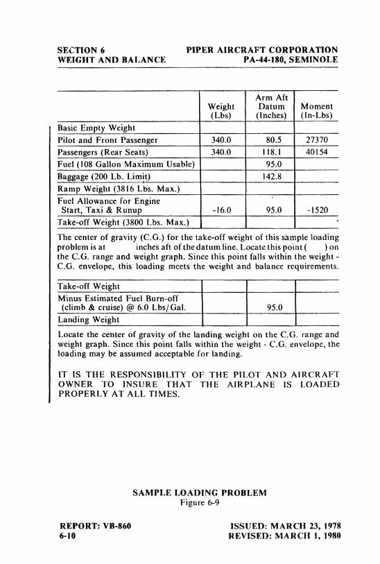
SECTION 6 PIPER AIRCRAFT CORPORATIONWEIGHT AND BALANCE PA-44-180, SEMINOLE
Arm AftWeight Datum Moment(Lbs) (Inches) (In-Lbs)
Basic Empty WeightPilot and Front Passenger 340.0 80.5 27370Passengers (Rear Seats) 340.0 118.1 40154
Fuel (108Gallon Maximum Usable) 95.0Baggage (200Lb. Limit) 142.8Ramp Weight (3816Lbs. Max.)Fuel Allowance for Engine
Start, Taxi & Runup-16.0
95.0-1520
Take-off Weight (3800Lbs. Max.)
The center of gravity (C.G.) for the take-off weight of this sample loadingproblem is at inches aft of the datum line. Locate this point ( ) onthe C.G. range and weight graph. Since this point falls within the weight -
C.G. envelope, this loading meets the weight and balance requirements.
Take-off WeightMinus Estimated Fuel Burn-off(climb& cruise) @ 6.0 Lbs/Gal. 95.0
Landing Weight
Locate the cehter of gravity of the landing weight on the C.G. range andweight graph. Since this point falls within the weight - C.G. envelope, theloading may be assumed acceptable for landing.
IT IS THE RESPONSIBILITY OF THE PILOT AND AlRCRAFTOWNER TO INSURE THAT THE AIRPLANE IS LOADEDPROPERLY AT ALL TIMES.
SAMPLE LOADING PROBLEMFigure 6-9
REPORT: VB-860 ISSUED: MARCH 23, 19786-10 REVISED: MARCH 1, 1980
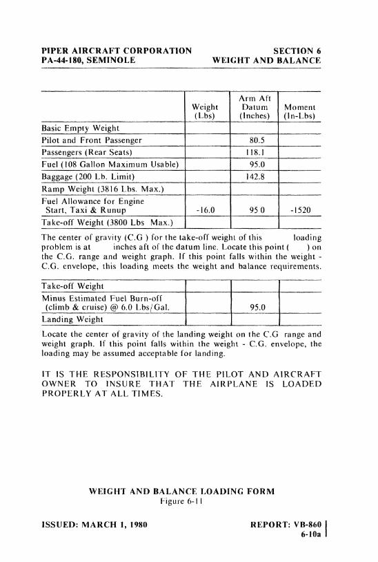
PIPER AIRCRAFT CORPORAT10N SECTION 6PA-44-180, SEMINOLE WEIGHT AND BALANCE
Arm AftWeight Datum Moment(Lbs) (Inches) (In-Lbs)
Basic Empty Weight
Pilot and Front Passenger 80.5Passengers (Rear Seats) 118.1Fuel (108Gallon Maximum Usable) 95.0Baggage (200Lb. Limit) 142.8Ramp Weight (3816 Lbs. Max.)Fuel Allowance for Engine
Start, Taxi & Runup-!6.0
95 0-1520
Take-off Weight (3800 Lbs Max.)
The center of gravity (C.G ) for the take-off weight of this loadingproblem is at inches aft of the datum line. Locate this point ( ) onthe C.G. range and weight graph. If this point falls within the weight -
C.G. envelope, this loading meets the weight and balance requirements.
Take-off WeightMinus Estimated Fuel Burn-off(climb& cruise) @ 6.0 Lbs/Gal. 95.0
Landing Weight
Locate the center of gravity of the landing weight on the C.G range andweight graph. If this point falls within the weight - C.G. envelope, theloading may be assumed acceptable for landing.
IT IS THE RESPONS1BltlTY OF THE PILOT AND AIRCRAFTOWNER TO INSURE THAT THE AIRPLANE IS LOADEDPROPERLY AT ALL TIMES.
WEIGHT AND BALANCE LOADING FORMFigure 6-\ I
ISSUED: MARCH 1, 1980 REPORT: VB-860 |6-10a 1
SECTION 6 PIPER AIRCRAFT CORPORATIONWEIGHT AND BALANCE PA-44-180, SEMINOLE
THIS PAGE lNTENTIONALLY LEFT BLANK
l REPORT: VB-860 ISSUED: MARCH 1, 19806-10b
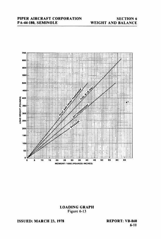
PIPER AIRCRAFT CORPORATION SECTION 6PA-44-180, SEMINOLE WEIGHT AND BALANCE
700
650
600
suo
600
aso-
400
360
aoo
250
200
150
1500
13 16 23 26 30 36 40 46 53 55 63 65
MOMENT/1000(POUNDS-INCHES)
LOADING GRAPHFigure 6-13
ISSUED: MARCH 23, 1978 REPORT: VB-8606-11
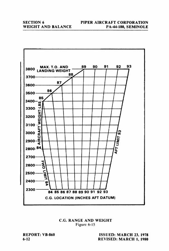
SECTION 6 PIPER AIRCRAFT CORPORATIONWEIGHT AND BALANCE PA-44-180, SEMINOLE
MAX. T.O. AND 89 90 91 92 933800 LANDING WEIGHT
88370 0
200087
86
863400-
3300.
3200 9 -- --
w3100 - ---
3000 ---
2900-
2800.84
2700-- ---
2600---i --
O
2500--- --
2400 m--
2300 84 85 86 87 88 89 90 91 92 93
C.G. LOCATION (INCHES AFT DATUM)
C.G. RANGE AND WEIGHTFigure 6-15
REPORT: VB-860 ISSUED: MARCH 23, 19786-12 REVISED: MARCH 1, 1980
PIPER AIRCRAFT CORPORATION SECTION 6PA-44-180, SEMINOLE WEIGHT AND BALANCE
6.9 INSTRUCTIONS FOR USING THE WEIGHT AND BALANCEPLOTTER
This plotter is provided to enable the pilot quickly and conveniently to:(a) Determine the total weight and C.G. position.(b) Decide how to change his load if his first loading is not within the
allowable envelope.
Heat can warp or ruin the plotter if it is left in the sunlight.Replacement plotters may be purchased from Piper dealers and distributors.
When the airplane is delivered, the basic weight and basic C.G. will berecorded on the computer. These should be changed any time the basicweight or C.G. location is changed.
The plotter enables the user to add weights and corresponding momentsgraphically. The effect of adding or disposing of useful load can easily beseen. The plotter does not cover the situation where cargo is loaded inlocations other than on the seats or in the baggage compartments.
Brief instructions are given on the plotter itself. To use it, first plot apoint on the grid to locate the basic weight and C.G. location. This can beput on more or less permanently because it will not change until the airplaneis modified. Next, position the zero weight end of any one of the loading slotsover this point. Using a pencil, draw a line along the slot to the weight whichwill be carried in that location. Then position the zero weight end of the nextslot over the end of this line and draw another line representing the weightwhich will be located in this second position. When all the loads have beendrawn in this manner, the final end of the segmented line locates the totalload and the C.G. position of the airplane for takeoff. If this point is notwithin the allowable envelope it will be necessary to remove fuel, baggage, orpassengers and /or to rearrange baggage and passengers to get the final pointto fall within the envelope.
Fuel burn-off and gear movement do not significantly affect the centerof gravity.
ISSUED: MARCH 23, 1978 REPORT: VB-8606-13
SECTION 6 PIPER AIRCRAFT CORPORATIONWEIGHT AND BALANCE PA-44-180, SEMINOLE
SAMPLE PROBLEM
A sample problem will demonstrate the use of the weight and balanceplotter.
Assume a basic weight and C.G. location of2364 pounds at 86.14 inchesrespectively. We wish to carry a pilot and 3 passengers. Two men weighing180 and 200 pounds will occupy the front seats, and two children weighing80 and 100 pounds will ride in the rear. Two suitcases weighing 25 poundsand 20 pounds respectively, will be carried in the rear compartment. We wishto carry 60 gallons of fuel. Will we be within the safe envelope?
(a) Place a dot on the plotter grid at 2364 pounds and 86.14 inches torepresent the basic airplane. (See illustration.)
(b) Slide the slotted plastic into position so that the dot is under the slotfor the forward seats, at zero weight.
(c) Draw a line up the slot to the 380 pound position (180+ 200) and puta dot.
(d) Continue moving the plastic and plotting points to account forweight in the rear seats (80+ 100), baggage compartment (45),andfuel tanks (360).
(e) As can be seen from the illustration, the final dot shows the totalweight to be 3329 pounds with the C.G. at 89.30. This is well withinthe envelope.
(f) There will be room for more fuel.
As fuel is burned off, the weight and C.G. will follow down the fuel lineand stay within the envelope for landing.
REPORT: VB-860 ISSUED: MARCH 23, 19786-14
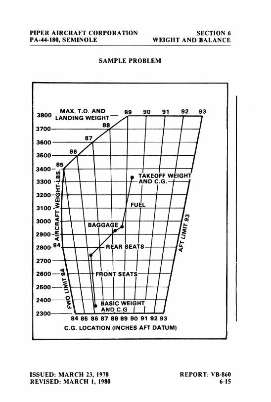
PIPER AIRCRAFT CORPORATION SECTION 6PA-44-180, SEMINOLE WEIGHT AND BALANCE
SAMPLE PROBLEM
MAX. T.O. AND E9 90 91 92 933800 LANDING WEIGHT¯883700
87
853400-
o TAKEOFF WEIGHT3300
-4
------- AND C.G.
3200-0 --- -
w3100 y FUEL
3000 <BAGGAGE
2900
2800 84 REAR SEATS
2700
2600--e FRONT SEATS
2500--E
2400- BASIC WEIGHT
2300AND C.G j j
84 86 86 87 88 89 90 91 92 93C.G. LOCATION (INCHES AFT DATUM)
ISSUED: MARCH 23, 1978 REPORT: VB-860REVISED: MARCH 1, 1980 6-15
SECTION 6 PIPER AIRCRAFT CORPORATIONWEIGHT AND BALANCE PA-44-180, SEMINOLE
THIS PAGE INTENTIONALLY LEFT BLANK
REPORT: VB-860 ISSUED: MARCH 23, 19786-16
TABLE OF CONTENTS
SECTION 7
DESCRIPTION AND OPERATIONOF THE AIRPLANE AND ITS SYSTEMS
Paragraph PageNo. No.
7.1 The Airplane..................................... 7-17.3 Airframe ........................................ 7-17.5 Engines .......................................... 7-27.7 Propellers ........................................ 7-57.9 Landing Gear ..................................... 7-67.11 Brake System ..................................... 7-127.13 Flight Control System.............................. 7-127.15 Fuel System ...................................... 7-147.17 Electrical System .................................. 7-167.19 Vacuum System ................................... 7-217.21 'Pitot Static System ................................ 7-237.23 Instrument Panel .................................. 7-257.25 Heating, Ventilating and Defrosting System . . . . .. . . . . . 7-277.27 Cabin Features.................................... 7-307.29 Stall Warning ................ ................... 7-327.31 Baggage Area ..................................... 1-327.33 Finish............................ ............... 7-327.35 Emergency Locator Transmitter . . . . . . . . . . . . . . . . . . . . . 7-337.37 Piper External Power .............................. 7-367.39 Propeller Synchrophaser............................ 7-367.41 Carburetor Ice Detection System ..................... 7-37
REPORT: VB-8607-i

PIPFR AIRCRAFT CORPORATION SECTION 7PA-44-180, SEMINOLE DESCRIPTION & OPERATION
SECTION 7
DESCRIPTION AND OPERATIONOF THE AIRPLANE AND ITS SYSTEMS
7.1 THE AIRPLANE
The Seminole is a twin-engine, all metal, retractable landing gear,airplane. It has seating for up to four occupants and has a two hundredpound capacity luggage compartment.
7.3 AIRFRAME
With the exception of the steel engine mounts and landing gear, thefiberglass nose cone, cowling nose bowls and tips of wings, and the ABSthermoplastic extremities (tail fin, rudder and stabilator), the basic airframeis of aluminum alloy. Aerobatics are prohibited in this airplane since thestructure is not designed for aerobatic loads.
The fuselage is a semi-monocoque structure with a passenger door onthe forward right side, a cargo door on the aft right side with an emergencyegress door on the forward left side.
The wing is of a semi-tapered design and employs a laminar flowNACA 65
-415
airfoil section. The main spar is located at approximately40% of the chord. The wings are attached to the fuselage by the insertion ofthe butt ends of the spar into a spar box carry-through, which is an integralpart of the fuselage structure. The bolting of the spar ends into the spar boxcarry-through structure, which is located under the rear seats, provides ineffect a continuous main spar. The wings are also attached fore and aft of themain spar by an auxiliary front spar and a rear spar. The rear spar, in addi-tion to taking torque and drag loads, provides a mount for flaps and aile-rons. The four-position wing flaps are mechanically controlled by a handlelocated between the front seats. When fully retracted, the right flap locksinto place to provide a step for cabin entry. Each nacelle contains one fueltank.
ISSUED: MARCH 23, 1978 REPORT: VB-8607-1
SECTION 7 PIPER AIRCRAFT CORPORATIONDESCRIPTION & OPERATION PA-44-180, SEMINOLE
A vertical stabilizer, an all-movable horizontal stabilator, and a ruddermake up the empennage. The stabilator, which is mounted on top of the fin,incorporates an anti-servo tab which provides longitudinal stability andtrim. This tab moves in the same direction as the stabilator, but with in-creased travel. Rudder effectiveness is increased by an anti-servo tab on therudder.
7.5 ENGINES
The aircraft is powered by two Lycoming four-cylinder engines, eachrated at 180 horsepower at 2700 RPM at sea level. The engines are air cooledand are equipped with oil coolers with low temperature bypass systems andengine-mounted oil filters. A winterization plate is provided to restrict airduring winter operation. (See Winterization in Section 8.) Asymmetricthrust during takeoff and climb is eliminated by the counter-rotation of theengines, the left engine rotating in a clockwise direction when viewed fromthe cockpit, and the right engine rotating counterclockwise.
The engines are accessible through removable cowls. The upper cowlhalf is attached with quarter-turn fasteners and is removable. Engine mountsare constructed of steel tubing, and dynafocal engine mounts are provided toreduce vibration.
The induction air box incorporates a manually operated two-way valvewhich allows the carburetor to receive either induction air which passesthrough the air filter or heated air which bypasses the filter. Carburetor heatselection provides heated air to the carburetor in the event of carburetoricing, and also allows selection of an alternate source of air in the event theinduction air source or the air filter becomes blocked with ice, snow, freezingrain, etc. Carburetor heat selection provides air which is unfiltered; there-fore, it should not be used during ground operation when dust or other con-taminants might enter the system. The primary (throughthe filter)inductionsource should always be used for takeoffs.
Engine controls consist of a throttle, a propeller control and a mixturecontrol lever for each engine. These controls are located on the controlquadrant on the lower center of the instrument panel where they aieaccessible to both the pilot and the copilot (Figure 7-1). The controls utilizeteflon-lined control cables to reduce friction and binding.
REPORT: VB-860 ISSUED: MARCH 23, 19787-2
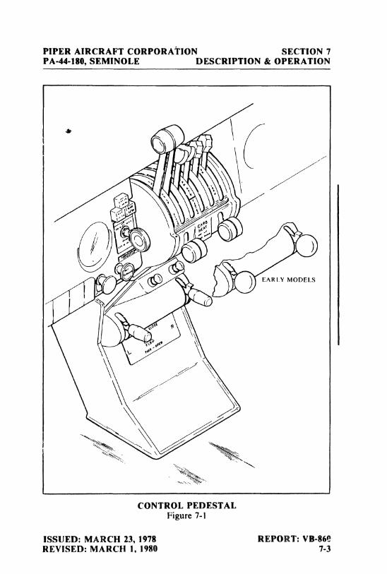
PIPER AIRCRAFT CORPORAÏION SECTION 7PA-44-180, SEMINOLE DESCRIPTION & OPERATION
EARLY MODELS
CONTROL PEDESTALFigure 7-1
ISSUED: MARCH 23, 1978 REPORT: VB-860REVISED: MARCH 1, 1980 7-3
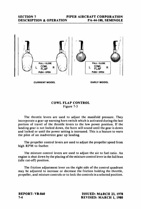
SECTION 7 PIPER AIRCRAFT CORPORATIONDESCRIPTION & OPERATION PA-44-180, SEMINOLE
PULL-CLOSE PULL-CLOSE
L COWL R L COWL RFLAP FLAPPUSH-OPEN PUSH-OPEN
CURRENT MODEL EARLY MODEL
COWL FLAP CONTROLFigure 7-3
The throttle levers are used to adjust the manifold pressure. Theyincorporate a gear up warning horn switch which is activated during the lastportion of travel of the throttle levers to the low power position. If thelanding gear is not locked down, the horn will sound until the gear is downand locked or until the power setting is increased. This is a feature to warnthe pilot of an inadvertent gear up landing.
The propeller control levers are used to adjust the propeller speed fromhigh RPM to feather.
The mixture control levers are used to adjust the air to fuel ratio. Anengine is shut down by the placing of the mixture control lever in the full lean(idlecut-off) position.
The friction adjustment lever on the right side of the control quadrantmay be adjusted to increase or decrease the friction holding the throttle,propeller, and mixture controls or to lock the controls in a selected position.
REPORT: VB-860 ISSUED: MARCH 23, 19787-4 REVISED: MARCH 1, 1980
PIPER AIRCRAFT CORPORATION SECTION 7PA-44·180, SEMINOLE DESCRIPTION & OPERATION
The carburetor heat controls are located on the control quadrant justbelow the engine control levers. When a carburetor heat lever is in the up, oroff, position the engine is operating on filtered air; when the lever is in thedown, or on, position the engine is operating on unfiltered, heated air.
The cowl flap control levers (Figure 7-3), located below the controlquadrant, are used to regulate cooling air for the engines. The levers havethree positions: full open, full closed, and intermediate. A lock incorporatedin each control lever locks the cowl flap in the selected position. To operatethe cowl flaps, depress the lock and move the lever toward the desiredsetting. Release the lock after initial movement and continue movement ofthe lever. The control will stop and lock into place at the next setting. T11elock must be depressed for each selection of a new cowl flap setting.
All throttle operations should be made with a smooth, not too rapidmovement to prevent unnecessary engine wear or damage to the engines.
7.7 PROPELLERS
Counter-rotation of the propellers provides balanced thrust duringtakeoff and climb and eliminates the "criticalengine" factor in single-engineflight.
Constant speed, controllable pitch and feathering Hartzell propellersare installed as standard equipment. The propellers mount directly to theengine crankshafts. Pitch is çontrolled by oil and nitrogen pressure. Oilpressure sends a propeller toward the high RPM or unfeather position;nitrogen pressure and a large spring sends a propeller toward the low RPMor feather position and also prevents propeller overspeeding. Governors,one on each engine, supply engine oil at various pressures through the pro-peller shafts to maintain constant RPM settings. A governor controls enginespeed by varying the pitch of the propeller to match load torque to enginetorque in response to changing flight conditions. The recommended nitro-gen pressure to be used when charging the unit is listed on placards on thepropeller domes and inside the spinners. This pressure varies with ambienttemperature at the time of charging. Although dry nitrogen gas is recom-mended, compressed air may be used provided it contains no moisture. Formore detailed instructions, see "Propeller Service" in Section 8 of thisHandbook.
ISSUED: MARCH 23, 1978 REPORT: VB-8607-5
SECTION 7 PIPER AIRCRAFT CORPORATIONDESCRIPTION & OPERATION PA-44-180, SEMINOLE
Each propeller is controlled by the propeller control levers located in thecenter of the power control quadrant. Feathering of a propeller is accom-plished by moving the control fully aft through the low RPM detent, into theFEATHER position. Feathering takes place in approximately six seconds.Unfeathering is accomplished by moving the propeller control forward andengaging the starter until the propeller is windmilling.
A feathering lock, operated by centrifugal force, prevents featheringduring engine shut down by making it impossible to feather any time theengine speed falls below 950 RPM. For this reason, when airborne, and thepilot wishes to feather a propeller to save an engine, he must be sure to movethe propeller control into the FEATHER position before the engine speeddrops below 950 RPM.
7.9 LANDING GEAR
The aircraft is equipped with hydraulically operated, fully retractable,tricycle landing gear.
Hydraulic pressure for gear operation is furnished by an electricallypowered, reversible hydraulic pump(refer to Figures 7-7 and 7-9). The pumpis activated by a two-position gear selector switch located to the left of thecontrol quadrant on the instrument panel (Figure 7-5). The gear selectorswitch, which has a wheel-shaped knob, must be pulled out before it ismoved to the UP or DOWN position. When hydraulic pressure is exerted inone direction, the gear is retracted; when it is exerted in the other direction,the gear is extended. Gear extension or retraction normally takes six to sevenseconds.
CAUTION
If the landing gear is in transit, and thehydraulic pump is running, it is NOT advisableto move the gear selector switch to the oppositeposition before the gear has reached its fulltravel limit, because a sudden reversal maydamage the electric pump.
REPORT: VB-860 ISSUED: MARCH 23, 19787-6 REVISED: MARCH 14, 1983
PIPER AIRCRAFT CORPORATION SECTION 7PA-44-180, SEMINOLE DESCRIPTION & OPERATION
The landing gear is designed to extend even in the event of hydraulicfailure. Since the gear is held in the retracted position by hydraulic pressure,should the hydraulic system fail for any reason, gravity will allow the gear toextend. When the landing gear is retracted, the main wheels retract inboardinto the wings and the nose wheel retracts aft into the nose section. Springsassist in gear extension and in locking the gear in the down position. Afterthe gears are down and the downlock hooks engage, springs maintain forceon each hook to keep it locked until it is released by hydraulic pressure.
To extend and lock the gears in the event of hydraulic failure, it isnecessary only to relieve the hydraulic pressure. An emergency gearextension knob, located directly beneath the gear selector switch is providedfor this purpose. Pulling this knob releases the hydraulic pressure holdingthe gear in the up position and allows the gear to fall free. Before pulling theemergency gear extension knob, place the landing gear selector switch in theDOWN position to prevent the pump from trying to raise the gear. If theemergency gear knob has been pulled out to lower the gear by gravity, due toa gear system malfunction, leave the control in itsextended position until theairplane has been put on jacks to check the proper function of the landinggear hydraulic and electrical systems. See the Service Manual for properlanding gear system check out procedures. If the airplane is being used fortraining purposes or a pilot check out mission, and the emergency gearextension knob has been pulled out, it may be pushed in again when desiredif there has not been any apparent malfunction of the landing gear system.
When the gear is fully extended or fully retracted and the gear selector isin the corresponding position, electrical limit switches stop the flow ofcurrent to the motor of the hydraulic pump. The three green lights directlyabove the landing gear selector switch illuminate to indicate that each of thethree landing gears is down and locked. A convex mirror on the left enginenacelle both serves as a taxiing aid and allows the pilot to visually confirmthe condition of the nose gear. If the gear is in neither the full up nor the fulldown position, a red warning light on the instrument panel illuminates.Should the throttle be placed in a low setting - as for a landing approach -
while the gear is retracted, a warning horn sounds to alert the pilot that thegear is retracted. The gear warning horn emits a 90 cycles per minute beepingsound.
ISSUED: MARCH 23, 1978 REPORT: VB-8607-7
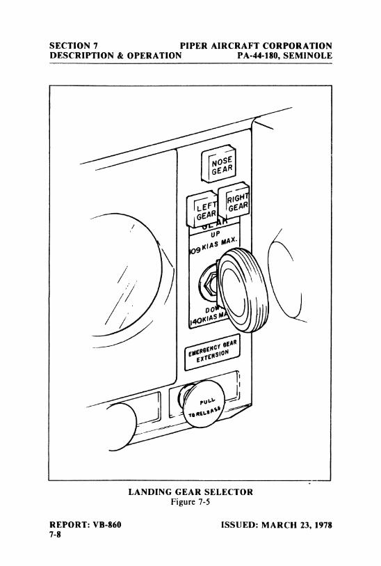
SECTION 7 PIPER AIRCRAFT CORPORATIONDESCRIPTION & OPERATION PA-44-180, SEMINOLE
GEAR
LANDING GEAR SELECTORFigure 7-5
REPORT: VB-860 ISSUED: MARCH 23, 19787-8
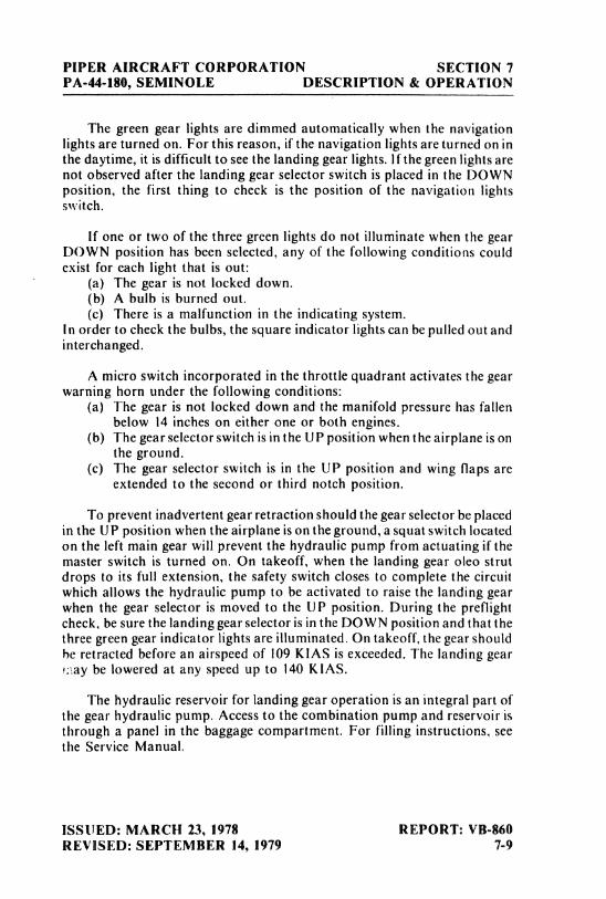
PIPER AIRCRAFT CORPORATION SECTION 7PA-44-180, SEMINOLE DESCRIPTION & OPERATION
The green gear lights are dimmed automatically when the navigationlights are turned on. For this reason, if the navigation lights are turned on inthe daytime, it is difficult to see the landing gear lights. If the green lights arenot observed after the landing gear selector switch is placed in the DOWNposition, the first thing to check is the position of the navigation lightsswitch.
If one or two of the three green lights do not illuminate when the gearDOWN position has been selected, any of the following conditions couldexist for each light that is out:
(a) The gear is not locked down.(b) A bulb is burned out.(c) There is a malfunction in the indicating system.
In order to check the bulbs, the square indicator lights can be pulled out andinterchanged.
A micro switch incorporated in the throttle quadrant activates the gearwarning horn under the following conditions:
(a) The gear is not locked down and the manifold pressure has fallenbelow 14 inches on either one or both engines.
(b) The gear selector switch is in the UP position when the airplane is onthe ground.
(c) The gear selector switch is in the UP position and wing flaps areextended to the second or third notch position.
To prevent inadvertent gear retraction should the gear selector be placedin the UP position when the airplane is on the ground, a squat switch locatedon the left main gear will prevent the hydraulic pump from actuating if themaster switch is turned on. On takeoff, when the landing gear oleo strutdrops to its full extension, the safety switch closes to complete the circuitwhich allows the hydraulic pump to be activated to raise the landing gearwhen the gear selector is moved to the UP position. During the preflightcheck, be sure the landing gear selector is in the DOWN position and that thethree green gear indicator lights are illuminated. On takeoff, the gear shouldbe retracted before an airspeed of 109 KIAS is exceeded. The landing gear
ay be lowered at any speed up to 140 KIAS.
The hydraulic reservoir for landing gear operation is an integral part ofthe gear hydraulic pump. Access to the combination pump and reservoir isthrough a panel in the baggage compartment. For filling instructions, seethe Service Manual.
ISSUED: MARCH 23, 1978 REPORT: VB-860REVISED: SEPTEMBER 14, 1979 7-9
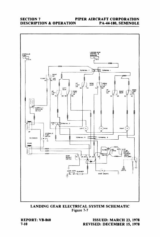
SECTION 7 PIPER AIRCRAFT CORPORATIONDESCRIPTION & OPERATION PA-44-180, SEMINOLE
TERMINAL TERMINAL I
FLGHT 5 0
No NC POS
uP ( NOSE DOWN1 LIMIT GEAN LimiT
LEFTSW
NC No NC N
NG NO NO NC NC NO 40 No
SWtrCH
II
00wN
GEAR HORN FLABRERLIGHTS
GEAR UNSAPE
LANDING GEAR ELECTRICAL SYSTEM SCHEMATICFigure 7-7
REPORT: VB-860 ISSUED: MARCH 23, 19787-10 REVISED: DECEMBER 15, 1978
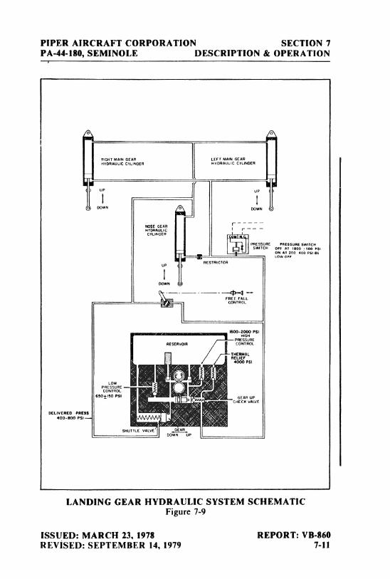
P1PER AIRCRAFT CORPORATION SECTION 7PA-44-180, SEMINOLE DESCRIPTION & OPERATION
RIGHT MAIN GEAR LEFT MAIN GEARBYORAutic CYL1NDER HYDRAULIC CYLlNDER
D WN DOWN
MOSE GEARHYORAULIC ¯ ¯
CYLINDER
14tESSURE PRESSURE SWITCHSWITCH OFF AT 1800 100 P5f
ONAT200 400PS18ELOW OFF
UPRESTRICTOR
DOWN
FREE FALLCONTROL
8600 2000 PSI
PRESSURERESERv R CONTROL
THERMALRELIEF
4000 PSI
LOWpcROENSSUORLE
6¾ © PM GEAR UPGHECM VALVE
DELIVERED PRESS400-800 PSt--.
SHUTTLE VALVE00 UP
LANDING GEAR HYDRAULIC SYSTEM SCHEMATICFigure 7-9
ISSUED: MARCH 23, 1978 REPORT: VB-860REVISED: SEPTEMBER 14, 1979 7-11
SECTION 7 PIPER AIRCRAFT CORPORATIONDESCRIPTION & OPERATION PA-44-180, SEMINOLE
The nose gear is steerable through a 30 degree arc either side of center byuse of a combination of full rudder pedal travel and brakes. A gearcentering spring, incorporated in the nose gear steering system, preventsshimmy tendencies. A bungee assembly reduces ground steering effort anddampens shocks and bumps during taxiing. When the gear is retracted, thenose wheel centers as it enters the wheel welÌ;and the steering linkagedisengages to reduce pedal loads in flight.
The main landing gear carries 6.00 x 6 , 8-ply tires. The nose wheel has a5.00 x 5, 6-ply tire. For information on servicing the tires, see "Tire inflation"in Section 8 of this Handbook.
Struts for the landing gear are air-oil assemblies. Strut exposure shouldbe checked during each preflight inspection. If a need for service or adjust-ment is indicated, refer to the instructions printed on the units. Should moredetailed landing gear service information be required, refer to the ServiceManual.
7.11 BRAKE SYSTEM
The brake system is designed to meet all normal braking needs. Twosingle-disc, double puck brake assemblies, one on each main gear, areactuated by toe brake pedals mounted on both the pilot's and copilot'srudder pedals. A brake system hydraulic reservoir, independent of thelanding gear hydraulic reservoir, is located in the rear top of the nosecompartment. Brake fluid should be maintained at the level marked on thereservoir. For further information see "Brake Service" in Section 8 of thisHandbook.
The parking brake is engaged by depressing the toe brake pedals andpulling out the parking brake knob located on the lower instiument paneladjacent to the throttle quadrant. The parking brake is released bydepressing the toe brake pedals and pushing in the parking brake knob,
7.13 FLIGHT CONTROL SYSTEM
Dual flight controls are installed as standard equiprnent. The controlsactuate the control surfaces through a cable system. The horizontal tailsurface (stabilator) is of the all movable slab type with an anti-servo tabmounted on the trailing edge. This tab, actuated by a control mounted on theconsole between the front seats, also acts as a longitudinal trim tab (refer toFigure 7-11).
REPORT: VB-860 ISSUED: MARCH 23, 19787-12
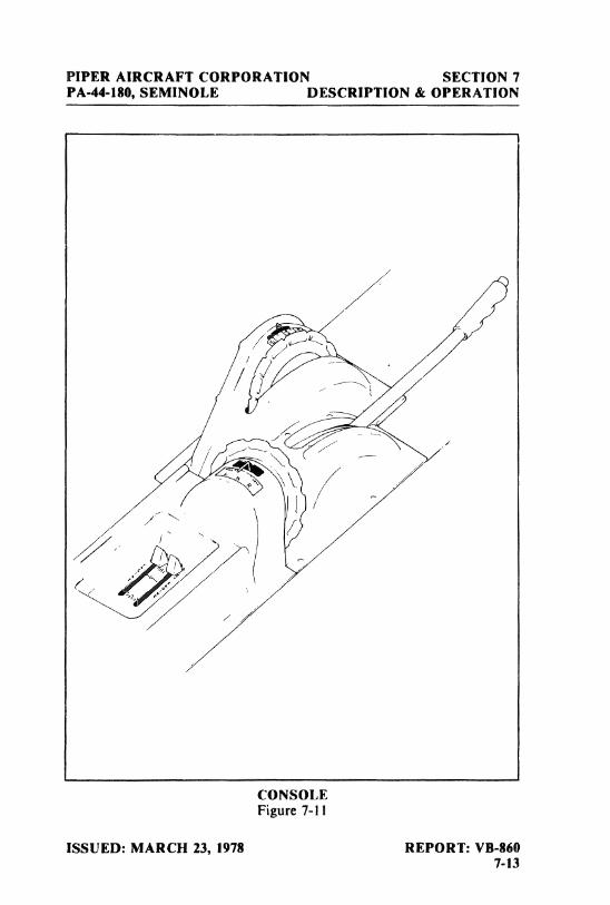
PIPER AIRCRAFT CORPORATION SECTION 7PA-44-180, SEMINOLE DESCRIPTION & OPERATION
CONSOLEFigure 7-I I
ISSUED: MARCH 23, 1978 REPORT: VB-8607-13
SECTION 7 PIPER AIRCRAFT CORPORATIONDESCRIPTION & OPERATION PA-44-180, SEMINOLE
The vertical tail is fitted with a rudder which incorporates a combinationrudder trim and anti-servo tab. The rudder trim control is located on thecontrol console between the front seats.
The flaps are manually operated and spring loaded to return to theretracted position. A four-position flap control lever (Figure 7-1 I) betweenthe front seats adjusts the flaps for reduced landing speeds and glide pathcontrol. The flaps have three extended positions - 10, 25 and 40 degrees - aswell as the fully retracted position. A button on the end of the lever must bedepressed before the control can be moved. A past center lock incorporatedin the actuating linkage holds the flap when it is in the retracted position sothat it may be used as a step on the right side. Since the flap will not support astep load except in the fully retracted position, the flaps should be retractedwhen people are entering or leaving the airplane.
7.15 FUEL SYSTEM
Fuel is stored in two 55 gallon fuel tanks, one in each nacelle (Figure7-13). One gallon of fuel in each nacelle is unusable, giving a total of 108usable gallons. The minimum fuel grade is 100/130 octane. The fuel tankvents, one installed under each wing, feature an anti-icing design to preventice formation from blocking the fuel tank vent lines.
Normally, fuel is supplied to the engines through engine-driven fuelpumps. Auxiliary electric fuel pumps serve as a back-up feature. Theelectric fuel pumps are controlled by rocker switches on the switch panel tothe left of the pilot. The electric fuel pumps should be ON during takeoffs
I and landings.
Fuel quantities and pressures are indicated on gauges on the instrumentpanel. There is a separate fuel quantity gauge for each tank. A calibrated fueldipstick is provided with the airplane. To visually check the quantity of fuelin a tank, insert the dipstick to the bottom of the tank, close off the pro-truding end with a finger, withdraw the dipstick, and read the fuel level. Themost accurate reading will be obtained with the airplane on level ground.
Fuel management controls are located on the console between the frontseats (Figure 7-I I). There is a control lever for each of the engines, and eachis placarded "ON" - "OFF" - "X FEED." During normal operation, thelevers are in the ON position, and each engine draws fuel from the tanks onthe same side as the engine. When the X FEED position is selected, theengine will draw fuel from the tank on the opposite side in order to extendrange and keep fuel weight balanced during single-engine operation. The
REPORT: VB-860 ISSUED: MARCH 23, 19787-14 REVISED: DECEMBER 15, 1978
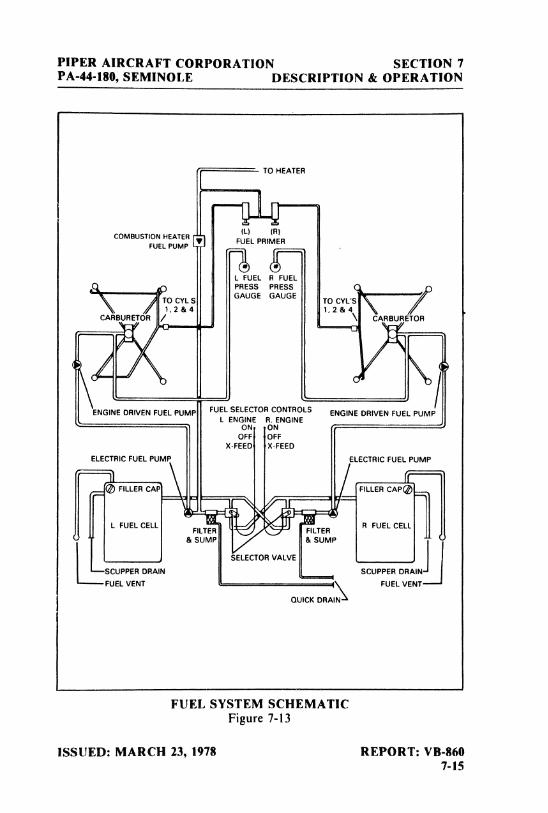
PIPER AIRCRAFT CORPORATION SECTION 7PA-44-180, SEMINOLE DESCRIPTION & OPERATION
TO HEATER
(L) (R)COMBUSTION HEATER
FUELPRIMERFUEL PUMP
L FUEL R FUELPRESS PRESSGAUGE GAUGE
TO CYL S
CARBURETOR / \ CARBURETOR
ENGINEDRIVEN FUEL PUMP FUELSELECTOR CONTROLS ENGINE DRIVEN FUEL PUMPL ENGINE R. ENGINE
ON ONOFF OFF
X-FEED X-FEEDELEC RICLFLt)ELPUM LECTRIRCFUAELPUMP
L FUEL CELL FILTER FILTER R FUEL CELL
&SUMP &SUMP
GELECTORVALVE
SCUPPER DRAIN SCUPPER DRAIN-
----FUEL VENT ( FUEL VENT
GUICKDRAIN-
FUEL SYSTEM SCHEMATICFigure 7-13
ISSUED: MARCH 23, 1978 REPORT: VB-8607-15
SECTION 7 PIPER AIRCRAFT CORPORATIONDESCRIPTION & OPERATION PA-44-180, SEMINOLE
OFF position shuts off the fuel flow to that engine.
NOTE
When one engine is inoperative and the fuelselector for the operating engine is on X FEEDthe selector for the inoperative engine must bein the OFF position. Do not operate with bothselectors on X FEED. Do not take off or landwith a selector on X FEED.
Before each flight, fuel must be drained from the low points in the fuelsystem to ensure that any accumulation of moisture or sediment is removedfrom the system. A fuel drain is provided for each halfof the fuel system. Thefuel drains are located on the right side of the fuselage just forward of theentrance step. (Refer to fuel draining procedure in paragraph 8.21, FuelSystem.)
7.17 ELECTRICAL SYSTEM
The electrical system is capable of supplying sufficient current forcomplete night IFR equipment. Electrical power is supplied by two 60ampere alternators (Figure 7-15), one mounted on each engine. A 35 ampere-hour, 12-volt battery provides current for starting, for use of electricalequipment when the engines are not running, and for a source of storedelectrical power to back up the alternator output. The battery, which islocated in the nose section is normally kept charged by the alternators. If itbecomes necessary to charge the battery, it should be removed from theairplane.
Two solid state voltage regulators maintain effective load sharing whileregulating electrical system bus voltage to 14-volts. An overvoltage relay ineach alternator circuit prevents damage to electrical and avionics equipmentby taking an alternator off the line if its output exceeds 17-volts. lf thisshould occur, the alternator light on the annunciator panel will illuminate.Voltage regulators and overvoltage relays are located in the nose section.
REPORT: VB-860 ISSUED: MARCH 23, 19787-16 REVISED: JANUARY 5, 1981
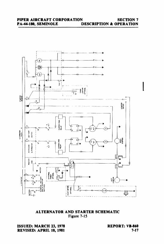
PIPER AIRCRAFT CORPORATION SECTION 7PA-44-180, SEMINOLE DESCRIPTION & OPERATION
ALTERNATOR AND STARTER SCHEMATICFigure 7-15
ISSUED: MARCH 23, 1978 REPORT: VB.860REVISED: APRIL 10, 1981 7-17
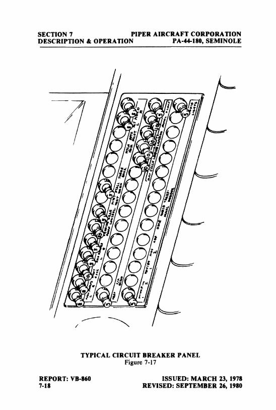
SECTION 7 PIPER AIRCRAFT CORPORATIONDESCRIPTION & OPERATION PA-44-180, SEMINOLE
I
,jO OO O
TYPICAL CIRCUIT BREAKER PANELFigure 7-17
REPORT: VB-860 ISSUED: MARCH 23, 19787-18 REVISED: SEPTEMBER 26, 1980
PIPER AIRCRAFT CORPORATION SECTION 7PA-44-180, SEMINOLE DESCRIPTION & OPERATION
The electrical system and equipment are protected by circuit breakerslocated on a circuit breaker panel on the lower right side of the instrumentpanel (Figure 7-17). The circuit breaker panel is provided with enough blankspaces to accommodate additional circuit breakers if extra electrical equip-ment is installed. In the event of equipment malfunctions or a sudden surgeof current, a circuit breaker can trip automatically. The pilot can reset thebreaker by pressing it in (preferably after a few minutes cooling period). Thecircuit breakers can be pulled out manually.
Most of the electrical switches, including the master switch and switchesfor magnetos, fuel pumps, starters, alternators, lights and pitot heat, areconveniently located on the switch panel (Figure 7-19) to the left of the pilot.
An optional light, mounted in the overhead panel, provides instru-ment and cockpit lighting for night flying. The light is controlled by arheostat switch located adjacent to the light. A map light window in thelens is actuated by an adjacent switch.
WARNING
Anti-collision lights should not be operatingwhen flying through cloud, fog or haze, sincethe reflected light can produce spatial disori-entation. Strobe lights should not be used inclose proximity to the ground, such as duringtaxiing, takeoff or landing.
Approximately 2000 RPM or more is required to obtain full alternatoroutput of 60 amperes. lt is normal to have zero output at idle RPM. This isdue to the reduced drive ratio from the engine. Dual ammeters and the ALTannunciator light provide a means of monitoring the electrical systemoperation. The two ammeters (loadmeters) indicate the output of the alter-nators. Should an ammeter indicate a load much higher than the knownconsumption of the electrical equipment in use, it should be suspected of amalfunction and turned off. In this event, the remaining alternator'sammeter should show a normal indication after approximately one minute.If both ammeters indicate a load much higher than the known consumptionfor more than approximately five minutes, an electrical defect other than thealternator system should be suspected because a discharged battery willreduce the alternator load as it approaches the charged conditions. A zeroammeter reading indicates an alternator is not producing current and shouldbe accompanied by illumination of the ALT annunciator light. A single
ISSUED: MARCH 23, 1978 REPORT: VB-860REVISED: JULY 24, 1981 7-19
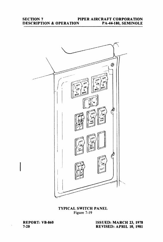
SECTION 7 PIPER AIRCRAFT CORPORATIONDESCRIPTION & OPERATION PA-44-180, SEMINOLE
REPORT: VB-860 ISSUED: MARCH 23, 19787-20 REVISED: APRIL 10, 1981
PIPER AIRCRAFT CORPORATION SECTION 7PA-44-180, SEMINOLE DESCRIPTION & OPERATION
alternator is capable of supporting a continued flight in case ofalternator osengine failure in most conditions, however, with deicing equipment andother high loads, care must be exercised to prevent the loads from exceedingthe 60 ampere rating and subsequent depletion of the battery. For abnormaland/or emergency operations and procedures, refer to Section 3 - Emer-gency Procedures.
An optional starting installation known as Piper External Power(PEP)is accessible through a receptacle located on the lower left side of the nosesection. An external battery can be connected to the socket, thus allowingthe operator to crank the engine without having to gain access to theairplane's battery.
CAUTION
Do not use cigar lighter receptacles as powersources for any devices other than the cigarlighters supplied with the airplane. Any otherdevice plugged into these receptacles may bedamaged.
7.19 VACUUM SYSTEM
The vacuum system operaies the air-driven gyro instruments Thevacuum system (Figure 7-21) consists of a vacuum pump on each engine,plus plumbing and regulating equipment.
The vacuum pumps are dry-type pumps, which eliminates the need foran air/ oil separator and its plumbing. A shear drive protects the engine fromdamage. If the drive shears, the gyros will become inoperative.
The vacuum gauge, mounted on the right instrument panel to the rightof the radios (refer to Figure 7-25), provides valuable information to thepilot about the operation of the vacuum system. A decrease in pressure in asystem that has remained constant over an extended period may indicateadirty filter, dirty screens, possibly a sticking vacuum regulator or leak insystem (a low vacuum indicator light is provided in the annunciator panel).Zero pressure would indicate a sheared pump drive, defective pump,possibly a defective gauge or collapsed line. In the event of any gaugevariation from the norm, the pilot should have a mechanic check the systemto prevent possible damage to the system components or eventual failure ofthe system.
ISSUED: MARCH 23, 1978 REPORT: VB-860REVISED: MARCH 14, 1983 7-21
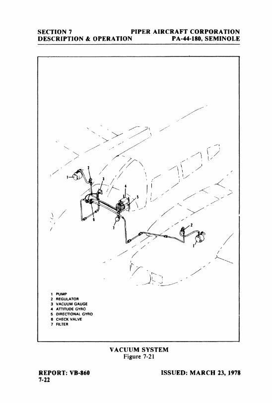
SECTION 7 PIPER AIRCRAFT CORPORATIONDESCRIPTION & OPERATION PA-44-180, SEMINOLE
1 PUMP
2 REGULATOR
3 VACUUM GAUGE4 ATTITUDEGYRO5 DIRECTIONALGYRO6 CHECKVALVE
7 FILTER
VACUUM SYSTEMFigure 7-21
REPORT: VB-860 ISSUED: MARCH 23, 19787-22
PIPER AIRCRAFT CORPORATION SECTION 7PA-44-180, SEMINOLE DESCRIPTION & OPERATION
A vacuum regulator is provided in the system to protect the gyros. Thevalve is set so the normal vacuum reads 4.8 to 5.2 inches of mercury, asettingwhich provides sufficient vacuum to operate all the gyros at their ratedRPM. Higher settings will damage the gyros and with a low setting the gyroswill be unreliable. The regulator is located behind the instrument panel.
7.21 PITOT STATIC SYSTEM
The pitot static system (Figure 7-23) supplies both pitot and staticpressure for the airspeed indicator and static pressure for the altimeter andvertical speed indicator (wheninstalled). Pitot and static pressure are pickedup by the pitot head on the bottom of the left wing.
The control valve for an alternate static source is located below the leftside of the instrument panel. When the valve is set in the alternate position,the altimeter, vertical speed indicator and airspeed indicator will be usingcabin air for static pressure. The storm window and cabin vents must beclosed and the cabin heater and defroster must be on during alternate staticsource operation. The altimeter error is less than 50 feet unless otherwiseplacarded.
To prevent bugs and water from entering the pitot and static pressureholes when the airplane is parked, a cover should be placed over the pitothead. A partially or completely blocked pitot head will give erratic or zeroreadings on the instruments.
NOTE
During preflight, check to make sure the pitotcover is removed.
An optional heated pitot head installation, which alleviates problemswith icing or heavy rain, is available. The switch for pitot heat is located onthe switch panel to the pilot's left. The pitot heat system has a separate circuitbreaker located in the circuit breaker panel and labeled "Pitot Heat." Theoperational status of the pitot heat system should be included in the preflightcheck.
ISSUED: MARCH 23, 1978 REPORT: VB-8607-23
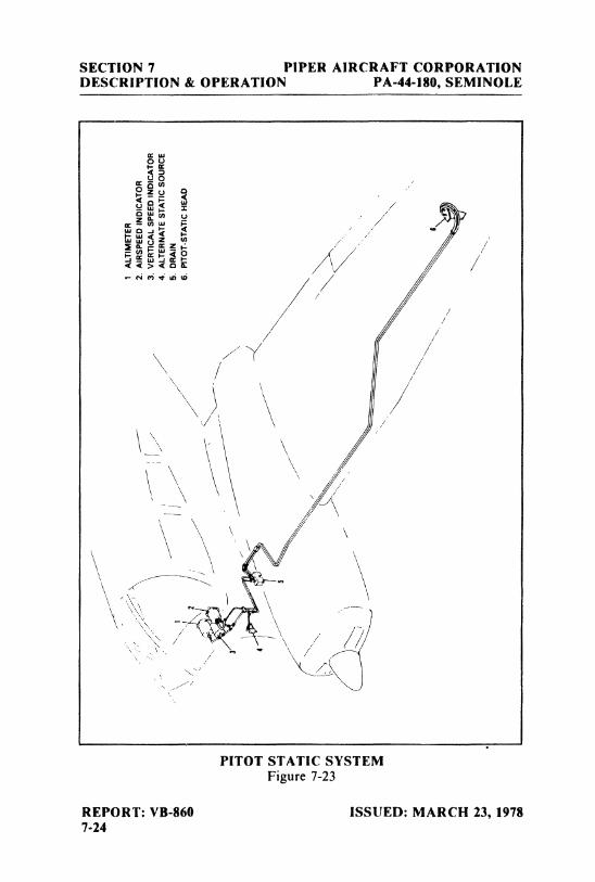
SECTION 7 PIPER AIRCRAFT CORPORATIONDESCRIPTION & OPERATION PA-44-l80, SEMINOLE
UO
PITOT STATIC SYSTEMFigure 7-23
REPORT: VB-860 ISSUED: MARCH 23, 19787-24
PIPER AIRCRAFT CORPORATION SECTION 7PA-44-180, SEMINOLE DESCRIPTION & OPERATION
CAUTION
Care should be exercised when checking theoperation of the heated pitot head. The unitbecomes very hot. Ground operation of pitotheat should be limited to 3 minutes maximumto avoid damaging the heating units.
7.23 lNSTRUMENT PANEL
Flight instruments are grouped in the upper instrument panel (Figure7-25); engine and electrical system monitoring instruments, the autopilot,and the circuit breaker panel are in the lower instrument panel. Left andright engine instruments are separated by the left control wheel shaft.
Radios are mounted in the center of the upper instrument panel. Anoptional radio master switch is located near the top of the instrument panelbetween the radio stacks. It controls the power to all radios through theaircraft master switch. An emergency bus switch is also provided to insureauxiliary power to the avionics bus in the event of a radio master switchcircuit failure. The emergency bus switch is located behind the lower rightshin guard left of the circuit breaker panel. The control quadrant - throttlesand propeller and mixture controls - is in the center of the lower instrumentpanel. To the left of the control quadrant is the landing gear selector.
Various warning lights are located with the pilot's flight instruments onthe left upper instrument panel. The gear unsafe warning light is to the left ofthe annunciator panel.
The annunciator panel, with oil pressure, gyro vacuum and alternatorlights, and incorporating a press-to-test feature, is located to the upper leftof the radios. The illumination of these lights in flight is an indication of apossible system malfunction. The pilot should closely monitor instrumentpanel gauges to check the condition of a system whose corresponding lighton the annunciator panel illuminates. During preflight, the operationalstatus of the annunciator panel should be tested by use of the press-to-testbutton. When the button is depressed, all annunciator panel lights shouldilluminaté.
NOTE
When an engine is feathered, the alternator,
gyro air and engine oil pressure annunciatorlights will remain illuminated.
ISSUED: MARCH 23, 1978 REPORT: VB-860REVISED: SEPTEMBER 14, 1979 7-25
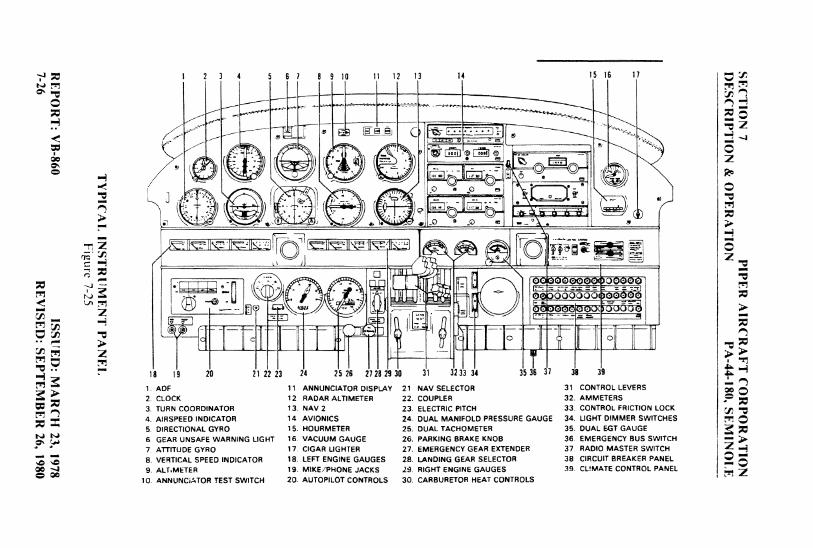
1 2 3 4 5 6 7 8 9 10 11 12 13 14 15 16 17 gy
1. ADF 11 ANNUNCIATORDISPLAY 21 NAV SELECTOR 31 CONTROL LEVERS2. CLOCK 12 RADAR ALTIMETER 22 COUPLER 32. AMMETERS3. TURN COORDINATOR 13. NAV 2 23. ELECTRICPITCH 33. CONTROL FRICTION LOCK
4. AIRSPEED INDICATOR 14 AVIONICS 24. DUAL MANIFOLDPRESSURE GAUGE 34. UGHT DIMMER SWITCHES6. DIRECTIONAL GYRO 15. HOURMETER 25. DUAL TACHOMETER 35. DUAL EGT GAUGE6. GEAR UNSAFE WARNING UGHT 18. VACUUM GAUGE 26. PARKING BRAKE KNOB 36. EMERGENCY BUS SWITCH
7. ATTITUDE GYRO 17. CIGAR UGHTER 27. EMERGENCY GEAR EXTENDER 37. RADIO MASTER SWITCH
8. VERTICAL SPEED INDICATOR 18. LEFT ENGINEGAUGES 28. LANDINGGEAR SELECTOR 38 CIRCUIT BREAKER PANEL
9. ALT.METER 19. MIKE/PHONE JACKS 29. RIGHT ENGINE GAUGES 39. CUMATE CONTROL PANEL
10. ANNUNCiATOR TEST SWITCH 20. AUTOPILOT CONTROLS 30. CARBURETOR HEAT CONTROLS
PIPER AIRCRAFT CORPORATION SECTION 7PA-44-180, SEMINOLE DESCRIPTION & OPERATION
Instrument panel lighting can be dimmed or brightened by rheostatswitches to the right of the control quadrant. Back-lights and a red floodlight are optional equipment. When instrument panel lights are turned on,annunciator lights are dimmed. However, they will not show dim when thepress-to-test swich is depressed.
7.25 HEATING, VENTILATING AND DEFROSTING SYSTEM
Heated air for cabin heat and windshield defrosting is provided by aJanitrol combustion heater located in the forward fuselage (referto Figure7-27). Air from the heater is distributed by a manifold to the ducts along thecabin floor to outlets at each seat and to the defroster outlets.
Operation of the combustion heater is controlled by a three-positionswitch located on the instrument panel (Figure 7-29) and labeled FAN, OFFand HEATER. Airflow and temperature are regulated by the three levers onthe instrument panel. The upper lever regulates air intake and the centerlever regulates cabin temperature. Cabin comfort can be maintained asdesired through various combinations of lever positions. Passengers havesecondary control over heat output by individually adjustable outlets ateach seat location. The third lever on the instrument panel controls thewindshield defrosters.
For cabin heat, the air intake lever on the instrument panel must bepartially or fully open and the three-position switch set to the HEATERposition. This simultaneously starts fuel flow and ignites the heater; and,during ground operation, it also activates the ventilation blower which is anintegral part of the combustion heater. With instant starting and no need forpriming, heat should be felt within a few seconds. When cabin air reaches thetemperature selected on the cabin temperature lever, ignition of the heatercycles automatically to maintain the selected temperature. Two safetyswitches activated by the intake valve and located aft of the heater unitprevent both fan and heater operation when the air intake lever is in theclosed position. A micro switch, which actuates when the landing gear isretracted, turns off the ventilation blower so that in flight the cabin air iscirculated by ram air pressure only.
When the three-position switch is in the FAN position during groundoperation, the ventilation fan blows fresh air through the heater duct workfor cabin ventilation and windshield defogging when heat is not desired.
ISSUED: MARCH 23, 1978 REPORT: VB-860REVISED: MARCH 1, 1980 7-27
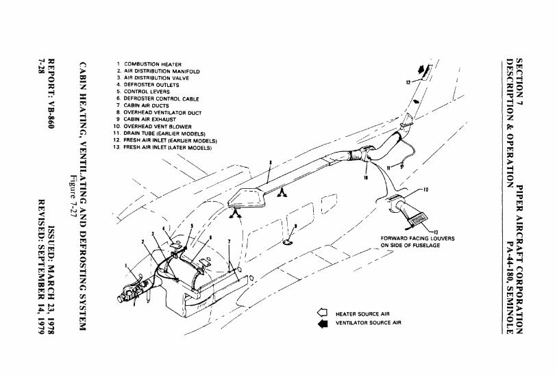
1 COMBUSTION HEATER2. AIR DISTRIBUTIONMANIFOLD3. AIR DISTRIBUTIONVALVE
124. DEFROSTER OUTLETS5. coNTROL LEVERS6. DEFROSTER CONTROL CABLE7. CABIN AIR DUCTS8. OVERHEADVENTILATOR DUCT9 CABINAIR EXHAUST
10. OVERHEADVENT BLOWEA11. DRAINTUBE (EARLIER MODELS)12. FRESH AIR INLET (EARLIER MODELS)13 FRESH AIR INLET(LATER MODELS)
FORWARD FACING L UVERSoN SIDE OF FUSELAGE
rr
HEATERSOURCE AIRVENTILATOR SOURCE AIR
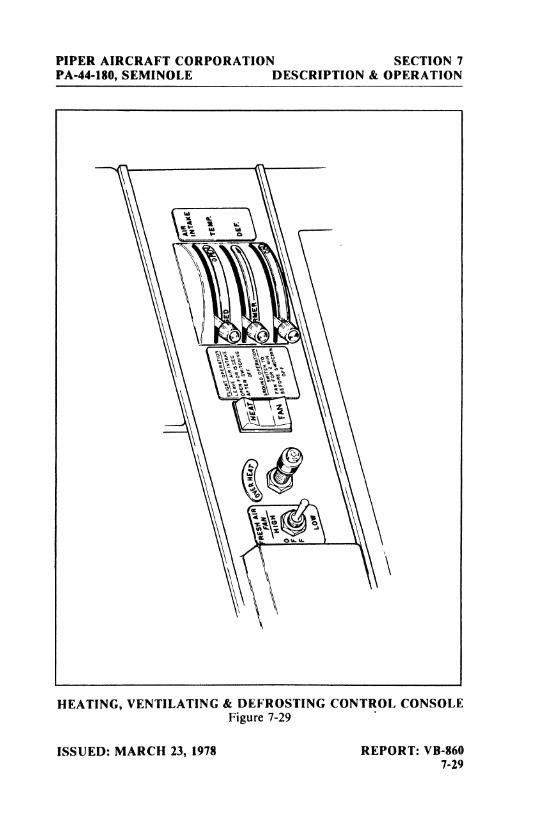
PIPER AIRCRAFT CORPORATION SECTION 7PA-44-180, SEMINOLE DESCRIPTION & OPERATION
HEATING, VENTILATING & DEFROSTING CONTROL CONSOLEFigure 7-29
ISSUED: MARCH 23, 1978 REPORT: VB-8607-29
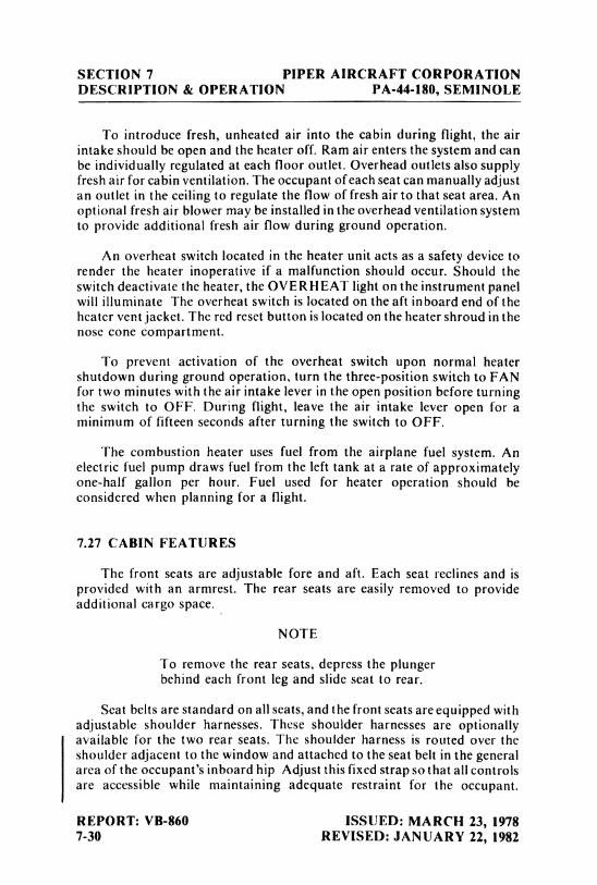
SECTION 7 PIPER AIRCRAFT CORPORATIONDESCRIPTION & OPERATION PA-44-180, SEMINOLE
To introduce fresh, unheated air into the cabin during flight, the airintake should be open and the heater off. Ram air enters the system and canbe individually regulated at each floor outlet. Overhead outlets also supplyfresh air for cabin ventilation. The occupant ofeach seat can manually adjustan outlet in the ceiling to regulate the flow of fresh air to that seat area. Anoptional fresh air blower may be installed in the overhead ventilation systemto provide additional fresh air flow during ground operation.
An overheat switch located in the heater unit acts as a safety device torender the heater inoperative if a malfunction should occur. Should theswitch deactivate the heater, the OVERH EAT light on the instrument panelwill illuminate The overheat switch is located on the aft inboard end of theheater vent jacket. The red reset button is located on the heater shroud in thenose cone compartment.
To prevent activation of the overheat switch upon normal heatershutdown during ground operation, turn the three-position switch to FANfor two minutes with the air intake lever in the open position before turningthe switch to OFF. During flight, leave the air intake lever open for aminimum of fifteen seconds after turning the switch to OFF.
The combustion heater uses fuel from the airplane fuel system. Anelectric fuel pump draws fuel from the left tank at a rate of approximatelyone-half gallon per hour. Fuel used for heater operation should beconsidered when planning for a flight.
7.27 CABIN FEATURES
The front seats are adjustable fore and aft. Each seat reclines and isprovided with an armrest. The rear seats are easily removed to provideadditional cargo space.
NOTE
To remove the rear seats, depress the plungerbehind each front leg and slide seat to rear.
Seat belts are standard on all seats, and the front seats are equipped withadjustable shoulder harnesses. These shoulder harnesses are optionallyavailable for the two rear seats. The shoulder harness is routed over theshoulder adjacent to the window and attached to the seat belt in the generalarea of the occupant's inboard hip Adjust this fixed strapso that all controlsare accessible while maintaining adequate restraint for the occupant.
REPORT: VB-860 ISSUED: MARCH 23, 19787-30 REVISED: JANUARY 22, 1982
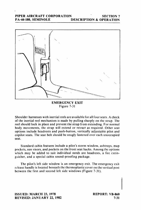
PIPER AIRCRAFT CORPORATION SECTION 7PA-44-180, SEMINOLE DESCRIPTION & OPERATION
EMERGENCY EXITFigure 7-3I
Shoulder harnesses with inertial reels are available for all four seats. A checkof the inertial reel mechanism is made by pulling sharply on the strap. Thereel should lock in place and prevent the strap from extending. For normalbody movements, the strap will extend or retract as required. Other seatoptions include headrests and push-button, vertically adjustable pilot andcopilot seats. The seat belt should be snugly fastened over each unoccupiedseat.
Standard cabin features include a pilot's storm window, ashtrays, mappockets, sun visors, and pockets on the front seat backs. Among the optionswhich may be added to suit individual needs are headrests, a fire extin-guisher, and a special cabin sound-proofing package.
The pilot's left side window is an emergency exit. The emergency exitrelease handle is located beneath the thermoplasticcover on the vertical postbetween the first and second left side windows (Figure 7-31).
ISSUED: MARCH 23, 1978 REPORT: VB-860REVISED: JANUARY 22, 1982 7-31
SECTION 7 PIPER AIRCRAFT CORPORATIONDESCRIPTION & OPERATION PA-44-180, SEMINOLE
CAUTION
The emergency exit is for ground use only.When released, the window will fall free fromthe fuselage
7.29 STALL WARNING
An approaching stall is indicated by a stall warning horn which isactivated between five and ten knots above stall speed Mild airframebuffeting and gentle pitching may also precede the stall Stall speeds areshown on a graph in the Performance Charts Section. The stall warningindication consists of a continuous sounding horn located behind the instru-ment panel. The stall warning horn has a different sound Irom that of thegear warning horn which has a 90 cycles per minute beepingsound. The stallwarning horn is activated by two lift detectors on the leading edge of the leftwing, outboard of the engine nacelle The inboard detector activates thehorn when the flaps are in the 25 and 40 degree positions, the outboard whenthe flaps are in other positions A squat switch in the stall warning systemdoes not allow the units to be activated on the ground.
7.31 BAGGAGE AREA
The 24 cubic foot baggage compartment, located aft of the seats, has aweight capacity of 200 pounds This compartment is loaded and unloadedthrough a separate 22 x 20 inch baggage door, and it is accessible duringflight. Tie-down straps are provided and they should be used at all times Thebaggage compartment and passenger doors use the same key.
NOTE
It is the pilot's responsibility to be sure whenbaggage is loaded that the airplane CG fallswithin the allowable C.G. range (See Weightand Balance Section.)
7.33 FINISH
l he standard exterior finish is painted with acrylic lacquer An optionalpolyurethane finish is also available To keep the finish attractive, economysite spray cans of touch-up paint are available from Piper Dealers
REPORT: VB-860 ISSUED: MARCH 23, 19787-32 REVISED: MARCH 14, 1983
PIPER AIRCRAFT CORPORATION SECTION 7PA-44-180, SEMINOLE DESCRIPTION & OPERATION
7.35 EMERGENCY LOCATOR TRANSMITTER*
The Emergency Locator Transmitter (ELT) meets the requirements ofFAR 91.52. It operates on self-contained batteries and is located in the aftfuselage section. It is accessible through a rectangular cover on the righthand side. A number 2 Phillips screwdriver is required to remove the cover.
A battery replacement date is marked on the transmitter. To complywith FAA regulations, the battery must be replaced on or before this dateThe battery must also be replaced if the transmitter has been used in anemergency situation or if the accumulated test time exceeds one hour, or ifthe unit has been inadvertently activated for an undetermined time period.
NOTE
If for any reason a test transmission isnecessary, the test transmission should beconducted only in the first five minutes of anyhour and limited to three audio sweeps. If testsmust be made at any other time. the tests shouldbe coordinated with the nearest FAA tower orflight service station.
NARCO ELT 10 OPERATION
On the ELT unit itself is a three position switch placarded "ON,""OFF"and "ARM." The ARM position sets the ELT so that it will transmit afterimpact and will continue to transmit until its battery is drained. The AR Mposition is selected when the ELT is installed in the airplane and it shouldremain in that position.
To use the ELT as a portable unit in an emergency, remove the cover andunlatch the unit from its mounting base. The antenna cable is disconnectedby a left quarter-turn of the knurled nut and a pull. A sharp tug on the twosmall wires will break them loose. Deploy the self-contained antenna bypulling the plastic tab marked "PULL FULLY TO EXTEND ANTENNA."Move the switch to ON to activate the transmitter.
*Optional equipment
ISSUED: MARCH 23, 1978 REPORT: VB-860REVISED: APRIL 13, 1979 7-33
SECTION 7 PIPER AIRCRAFT CORPORATIONDESCRIPTION & OPERATION PA-44-180, SEMINOLE
In the event the transmitter is activated by an impact, it can only beturned off by moving the switch on the ELT unit to OFF. Normal operationcan then be restored by pressing the small clear plastic reset button locatedon the top of the front face of the ELTand then moving the switch to ARM.
A pilot's remote switch located on the left side panel is provided to allowthe transmitter to be turned on from inside the cabin. The pilot's remoteswitch is placarded "ON" and "ARMED." The switch is normally in theARMED position. Moving the switch to ON will activate the transmitter.Moving the switch back to the ARMED position will turn off thetransmitter only if the impact switch has not been activated.
The ELT should be checked to make certain the unit has not beenactivated during the ground check. Check by selecting 121.50 MHz on anoperating receiver. If there is an oscillating chirping sound, the ELT mayhave been activated and should be turned off immediately. This requiresremoval of the access cover and moving the switch to OFF, then press thereset button and return the switch to ARM. Recheck with the receiver toascertain the transmitter is silent.
CCC CIR I I-2 OPERATION
On the unit itself is a three position selector switch placarded "OFF,""ARM" and "ON." The ARM position is provided to set the unit to theautomatic position so that it will transmit only after impact and willcontinue to transmit until the battery is drained to depletion or until theswitch is manually moved to the OFF position. The ARM position isselected when the transmitter is installed at the factory and the switch shouldremain in that position whenever the unit is installed in the airplane. The ONposition is provided so the unit can be used asa portable transmitter or in theevent the automatic feature was not triggered by impact or to periodicallytest the function of the transmitter.
Select the OFF position when changing the battery, when rearming theunit if it has been activated for any reason, or to discontinue transmission.
NOTE
If the switch has been placed in the ON positionfor any reason, the OFF position has to beselected before selecting ARM. If ARM isselected directly from the ON position, the unitwill continue to transmit in the AR M position.
REPORT: VB-860 ISSUED: MARCH 23, 19787-34 REVISED: APRIL 13, 1979
PIPER AIRCRAFT CORPORATION SECTION 7PA-44-180, SEMINOLE DESCRIPTION & OPERATION
A pilot's remote switch, located on the left side panel, is provided toallow the transmitter to be controlled from inside the cabin. The pilot'sremote switch is placarded "ON,""AUTO/ ARM"and OFF/ RESET."Theswitch is normally left in the AUTO/ ARM position. To turn the transmitteroff, move the switch momentarily to the OFFjRESET position. Theaircraft master switch must be ON to turn the transmitter OFF. To actuatethe transmitter for tests or other reasons, move the switch upward to the ONposition and leave it in that position as long as transmission is desired.
The unit is equipped with a portable antenna to allow the locator to beremoved from the aircraft in case of an emergency and used as a portablesignal transmitter.
The locator should be checked during the ground check to make certainthe unit has not been accidentally activated. Check by tuning a radioreceiver to 121.50 MHz. If there is an oscillating sound, the locator may havebeen activated and should be turned off immediately. Reset to the ARMposition and check again to insure against outside interference.
ISSUED: DECEMBER 15, 1978 REPORT: VB-860REVISED: APRIL 13, 1979 7-35
SECTION 7 PIPER AIRCRAFT CORPORATIONDESCRIPTION & OPERATION PA-44-180, SEMINOLE
7.37 PIPER EXTERNAL POWER*
An optional starting installation known as Piper External Power (PEP)allows the airplane engine to be started from an external battery without thenecessity of gaining access to the airplane battery. The cable from theexternal battery can be attached to a receptacle under the right side of thenose section of the fuselage. Instructions on a placard located on the cover ofthe receptacle should be followed when starting with external power. Forinstructions on the use of the PEP, refer to Starting Engines - Section 4
7.39 PROPELLER SYNCHROPHASER*
A propeller synchrophaser installation is available as optional equip-ment. Its function is to maintain both propellers at the same RPM and at apreselected phase angle. This eliminates the propeller "beat" effect andminimizes vibration. When the synchrophaser is installed, the left engine isestablished as the master engine, and the right engine is equipped with a slavegovernor which automatically maintains its RPM with theleft engine RPM.When the propeller synchrophaser is installed, a two-position switch islocated on the throttle quadrant below the propeller controls. It is labeled"MANUAL" for manual control or standby and "AUTO SYNC" forpropeller synchrophaser.
During taxi, takeoff, landing or single engine operations the propellersynchrophaser switch should be in the MANUAL position. During cruise,propellers should be synchronized manually to within approximately 10RPM and the switch placed in the AUTO SYNC position. Normally,propeller synchrophasing will take place within a few seconds, but occa-sionally it may take up to a full minute. When the power setting is to bechanged, the synchrophaser switch should be set to MANUAL for 30seconds before the power setting is adjusted; then the synchrophaser switchmay be returned to the AUTO SYNC position. If the propeller RPMdifferential exceeds 50 RPM, the switch should be placed on MANUAL for30 to 40 seconds; then the propellers can be synchronized again and thesynchrophaser switch returned to AUTO SYNC. Pulling the circuit breakerscompletely deactivates the propeller synchrophaser system. If the masterswitch is turned OFF or if there is an electrical system failure, the slaveengine will return to the controlled, selected RPM plus approximately 25RPM's "out of synchronization" regardless of the position of the synchro-phaser switch.
*Optional equipment
REPORT: VB-860 ISSUED: APRIL 13, 19797-36
PIPER AIRCRAFT CORPORATION SECTION 7PA-44-180, SEMINOLE DESCRIPTION & OPERATION
7.41 CARBURETOR ICE DETECTION SYSTEM
A carburetor ice detection system is available as an option on thisairplane.
The system consists of a control box mounted on the instrument panel,a probe sensor mounted in the carburetor and a red warning light to indicatethe presence of ice in the carburetor.
If ice is present, apply full carburetor heat. Refer to 3 37, Carburetoricing, in the emergency procedures.
To adjust the system for critical ice detection, first turn on theairplane'smaster switch and then turn on the ice detection unit. Turn the sensitivityknob fully counterclockwise causing the carb ice light to come on. Now,rotate the sensitivity knob back (clockwise)until the ice light just goes out.This establishes the critical setting,
WARNING
This instrument is approved as optional equip-ment only and Flight Operations should not bepredicated on its use.
ISSUED: MARCH 1, 1980 REPORT: VB-8607-37

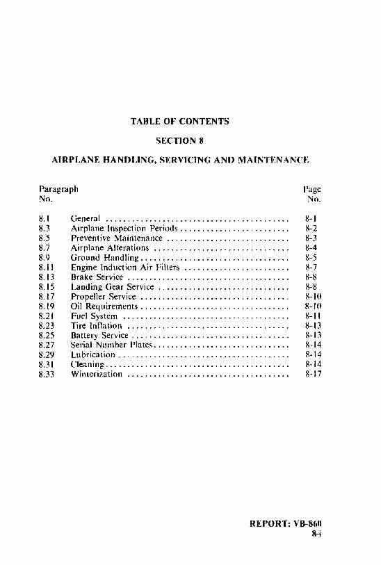
TABLE OF CONTENTS
SECTION 8
AIRPLANE HANDLING, SERVICING AND MAINTENANCE
Paragraph PageNo. No.
8.I General .......................................... 8-18.3 Airplane Inspection Periods......................... 8-28.5 Preventive Maintenance ............................ 8-38.7 Airplane Alterations ............................... 8-48.9 Ground Handling.................................. 8-58.11 Engine Induction Air Filters ........................ 8-78.13 Brake Service ..................................... 8-88.15 Landing Gear Service .............................. 8-88.17 Propeller Service .................................. 8-108.19 Oil Requirements.................................. 8-108.21 Fuel System ................. . .. .............. 8-118.23 Tire Inflation ..................................... 8-138.25 Battery Service .................................... 8-138.27 Serial Number Plates............................... 8-148.29 Lubrication ................... .... .............. 8-148.31 Cleaning.......................................... 8-148.33 Winterization ..................................... 8-17
REPORT: VB-8608-i

PIPER AIRCRAFT CORPORATION SECTION 8PA-44-180, SEMINOlE HANDI ING, SERV & MAINT
SECTION 8
AIRPI ANE HANDLING, SERVICING, AND MAINTENANCE
8.1 GENERAL
This section provides guidelines relating to the handling, servicing. andmaintenance of the Seminole For complete maintenance instructions, referto the PA-44-180 Maintenance Manual.
Every owner should stay in close contact with an authorized PiperService Center or Piper's Customer Service Department to obtain the latestinformation pertaining to their airplane, and to avail himself of PiperAircraft's support systems
Piper Aircraft Corporation takes a continuing interest in having theowner get the most efficient use from his airplane and keeping it in the bestmechanical condition Consequently, Piper Aircraft, from time to time,issues service releases including Service Bulletins, Service Letters, ServiceSpares Letters, and others relating to the aircraft.
Service Bulletins are of special importance and Piper considerscompliance mandatory These are sent directly to the latest FAA-registeredowners in the United States (U.S.) and Piper Service Centers worldwideDepending on the nature of the release, material and labor allowances mayapply. This information is provided to all authori7ed Service Centers
Service Letters deal with product improvements and servicingtechniques pertaining to the airplane. They are sent to Piper Service Centersand, if necessary, to the latest FAA-registered owners in the US Ownersshould give careful attention to Service I etter information
Service Spares Letters offer improved parts, kits, and optionalequipment which were not available originally and which may be of interestto the owner
ISSUED: MARCH 23, 1978 REPORT: VB-860REVISED: MARCH 4, 1989 8-1
SECTION 8 PIPER AIRCRAFT CORPORATIONHANDLING, SERV & MAINT PA-44-180, SEMINOLE
Piper Aircraft Corporation offers a subscription service for the ServiceBulletins, Service Letters, and Service Spares Letters. This service isavailable to interested persons, such as owners, pilots, and mechanics at anominal fee, and may be obtained through an authorized Piper ServiceCenter or Piper's Customer Services Department.
Maintenance manuals, parts catalogs, and revisions to both, areavailable from Piper Service Centers or Piper's Customer ServicesDepartment.
Any correspondence regarding the airplane should include the airplanemodel and serial number to ensure proper response.
8.3 AIRPLANE INSPECTION PERIODS
Piper Aircraft Corporation has developed inspection items and requiredinspection intervals (i.e.:50, 100, 500, and 1000 hours)for the specific modelaircraft. Appropriate forms are contained in the applicable PiperService/ Maintenance Manual, and should be complied with by a properlytrained, knowledgeable, and qualified mechanic at a Piper AuthorizedService Center or a reputable repair shop. Piper Aircraft Corporationcannot accept responsibility for the continued airworthiness of any aircraftnot maintained to these standards, and/or not brought into compliance withapplicable Service Bulletins issued by Piper Aircraft Corporation,instructions issued by the engine, propeller, or accessory manufacturers, orAirworthiness Directives issued by the FAA.
A programmed inspection, approved by the Federal AviationAdministration (FAA), is also available to the owner. This involves routineand detailed inspections to allow maximum utilization of the airplane.Maintenance inspection costs are reduced, and the maximum standard ofcontinued airworthiness is maintained. Complete details are available fromPiper Aircraft Corporation.
ln addition, but in conjunction with the above, the FAA requiresperiodic inspections on all aircraft to keep the Airworthiness Certificate ineffect. The owner is responsible for assuring compliance with theseinspection requirements and for maintaining proper documentation inlogbooks and/or maintenance records.
REPORT: VB-860 ISSUED: MARCH 23, 19788-2 REVISED: MARCH 4, 1989
PIPER AIRCRAFT CORPORATION SECTION 8PA-44-180, SEMINOLE HANDLING, SERV & MAINT
A spectographic analysis of the engine oil is available from several
sources. This inspection, if performed properly, provides a good check of theinternal condition of the engine. To be accurate,induction air filters must becleaned or changed regularly, and oil samples must be taken and sent in atregular intervals.
8.5 PREVENTIVE MAINTENANCE
The holder of a Pilot Certificate issued under FAR Part 61 may performcertain preventive maintenance described in FAR Part43. This maintenance
may be performed only on an aircraft which the pilot owns or operates andwhich is not used to carry persons or property for hire. Although suchmaintenance is allowed by law, each individual should make a self-analysis
as to whether he has the ability to perform the work.
All other maintenance required on the airplane should be accomplishedby appropriately licensed personnel.
If maintenance is accomplished, an entry must be made in theappropriate logbook. The entry should contain:
(a) The date the work was accomplished.(b) Description of the work.
(c) Number of hours on the aircraft.(d) The certificate number of pilot performing the work.(e) Signature of the individual doing the work.
ISSUED: MARCH 23, 1978 REPORT: VB-860REVISED: MARCH 4, 1989 8-3
SECTION 8 PIPER AIRCRAFT CORPORATIONHANDLING, SERV & MAINT PA-44-180, SEMINOLE
I8.7 AIRPLANE ALTERATIONS
If the owner desires to have his aircraft modified, he must obtain FAAapproval for the alteration. Major alterations accomplished in accordancewith Advisory Circular 43 13-2, when performed by an A & P mechanic,may be approved by the local FAA office Major alterations to the basicairframe or systems not covered by AC43.13-2require a Supplemental TypeCertificate.
The owner or pilot is required to ascertain that the following AircraftPapers are in order and in the aircraft.
(a) To be displayed in the aircraft at all times:(I) Aircraft Airworthiness Certificate Form FAA-8100-2(2) Aircraft Registration Certificate Form FAA-8050-3.(3) Aircraft Radio Station License if transmitters are installed
(b) To be carried in the aircraft at all times.(I) Pilot's Operating Handbook(2) Weight and Balance data plus a copy of the latest Repair
and Alteration Form FAA-337, if applicable.(3) Aircraft equipment list.
Although the aircraft and engine logbooks are not required to be in theaircraft, they should be made available upon request. Logbooks should becomplete and up to date. Good records will reduce maintenance cost bygiving the mechanic information about what has or has not beenaccomplished
REPORT: VB-860 ISSUED: MARCH 23, 19788-4 REVISED: MARCH 14, 1983
PIPER AIRCRAFT CORPORATION SECTION 8PA-44-180, SEMINOLE HANDLING, SERV & MAINT
8.9 GROUND HANDLING
(a) Towing
The airplane may be moved on the ground by the use of the nosewheel steering bar that is stowed in the baggage compartment or bypower equipment that will not damage or excessively strain the nosegear steering assembly.
CAUTIONS
When towing with power equipment, do notturn the nose gear beyond its steering radius ineither direction, as this will result in damage tothe nose gear and steering mechanism.
Do not tow the airplane when the controls aresecured.
In the event towing lines are necessary, ropes should beattached to both main gear struts as high up on the tubes as possible.Lines should be long enough to clear the nose and/or tail by not lessthan fifteen feet, and a qualified person should ride in the pilot's seatto maintain control by use of the brakes.
(b) Taxiing
Before attempting to taxi the airplane, ground personnelshould be instructed and approved by a qualified person authorizedby the owner. Engine starting and shut-down procedures as well astaxi techniques should be covered. When it is ascertained that thepropeller back blast and taxi areas are clear, power should beapplied to start the taxi roll, and the following checks should beperformed:
(1) Taxi a few feet forward and apply the brakes to determinetheir effectiveness.
(2) Taxi with the propeller set in low pitch, high RPM setting.(3) While taxiing, make slight turns to ascertain the effective-
ness of the steering.(4) Observe wing clearance when taxiing near buildings or
other stationary objects. If possible, station -an observeroutside the airplane.
(5) When taxiing over uneven ground, avoid holes and ruts.
ISSUED: MARCH 23, 1978 REPORT: VB-8608-5
SECTION 8 PIPER AIRCRAFT CORPORATIONHANDLING, SERV & MAINT PA-44-180, SEMINOLE
(6) Do not operate the engine at high RPM when running upor taxiing over ground containing loose stones, gravel, orany loose material that may cause damage to the propellerblades.
(c) Parking
When parking the airplane, be sure that it is sufficientlyprotected from adverse weather conditions and that it presents nodanger to other aircraft. When parking the airplane for any lengthof time or overnight, it is suggested that it be moored securely.
(1) To park the airplane, head it into the wind if possible.(2) Set the parking brake by depressing the toe brakes and
pulling out the parking brake control. To release theparking brake, depress the toe brakes and push in theparking brake control, then release the toe brakes.
CAUTION
Care should be taken when setting brakes thatare overheated or during cold weather whenaccumulated moisture may freeze a brake.
(3) Aileron and stabilator controls should be secured with thefront seat belt and chocks used to properly block thewheels.
(d) Mooring
The airplane should be moored for immovability, security andand protection. The following procedures should be used for theproper mooring of the airplane:
(1) Head the airplane into the wind if possible.(2) Retract the flaps.(3) Immobilize the ailerons and stabilator by looping the seat
belt through the control wheel and pulling it snug.(4) Block the wheels.(5) Secure tie-down ropes to the wing tie-down rings and to the
tail skid at approximately 45 degree angles to the ground.When using rope of non-synthetic material, leave sufficientslack to avoid damage to the airplane should the ropescontract.
REPORT: VB-860 ISSUED: MARCH 23, 19788-6
PIPER AIRCRAFT CORPORATION SECTION 8PA-44-180, SEMINOLE HANDLING, SERV & MAINT
CAUTION
Use bowline knots, square knots or locked slipknots. Do not use plain slip knots.
NOTE
Additional preparations for high winds includeusing tie-down ropes from the landing gearforks and securing the rudder.
(6) Install a pitot head cover ifavailable. Besure to remove thepitot head cover before flight.
(7) Cabin and baggage doors should be locked when theairplane is unattended.
8.11 ENGINE INDUCTION AIR FILTERS
(a) Removing Induction Air Filter
(1) Remove the upper cowling to gain access to the air filterbox.
(2) Turn the three studs and remove the air filter box cover.(3) Lift the air filter from the filter box.
(b) Cleaning Induction Air Filters
The induction air filters must be cleaned at least once every 50hours, and more often, even daily, when operating in dustyconditions. Extra filters are inexpensive, and a spare should be kepton hand for use as a rapid replacement.
To clean the filter:(1) Tap filter gently to remove dirt particles. Do not use
compressed air or cleaning solvents.(2) Inspect filter. If paper element is torn or ruptured or gasket
is damaged, the filter should be replaced. The usable life ofthe filter should be restricted to one year or 500 hours,whichever comes first.
ISSUED: MARCH 23, 1978 REPORT: VB-8608-7
SECTION 8 PIPER AIRCRAFT CORPORATIONHANDLING, SERV & MAINT PA-44-180, SEMINOLE
(c) Installation of Induction Air Filters
After cleaning, place filter in air box and install cover. Securecover by turning studs. Replace cowl.
8.13 BRAKE SERVICE
The brake system is filled with MIL-H-5606 (petroleumbase) hydraulicbrake fluid. This should be checked periodically or at every 50-hourinspection and replenished when necessary. The brake reservoir is located inthe forward maintenance area. Remove the four screws and rotate thefiberglass nose cone forward and down. The reservoir is located at the toprear of the compartment. Keep the fluid level at the level marked on thereservoir.
No adjustment of brake clearance is necessary. Refer to the ServiceManual for brake lining replacement instructions.
8.15 LANDING GEAR SERVICE
Two jack points are provided for jackingthe aircraft for servicing. Oneis located outboard of each main landing gear. Before Jacking,attach a tailsupport to the tail skid. Approximately 500 pounds of ballast should beplaced on the tail support.
CAUTION
Be sure to apply sufficient support ballast;otherwise the airplane may tip forward, and thenose section could be damaged.
Landing gear oleos should be serviced according to instruction on theunits. Under normal static load (emptyweight of airplane plus full fuel andoil), main oleo struts should be exposed 2.60 inches and the nose oleo strutshould be exposed 2.70 inches. Refer to the Service Manual for completeinformation on servicing oleo struts.
REPORT: VB-860 ISSUED: MARCH 23, 19788-8
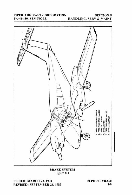
PIPER AIRCRAFT CORPORATION SECTION 8PA-44-180, SEMINOLE HANDLING, SERV & MAINT
I
BRAKE SYSTEMFigure 8-1
ISSUED: MARCH 23, 1978 REPORT: VB-860REVISED: SEPTEMBER 26, 1980 8-9
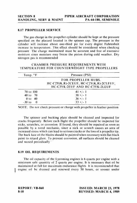
SECTION 8 PIPER AIRCRAFT CORPORATIONHANDLING, SERV & MAINT PA-44-180, SEMINOLE
8.17 PROPELLER SERVICE
The gas charge in the propeller cylinder should be kept at the pressurespecified on the placard located in the spinner cap. The pressure in thecylinder will increase about one-third psi for every degree Fahrenheitincrease in temperature. This effect should be considered when checkingpressure The charge maintained must be accurate and free of excessivemoisture since moisture may freeze the piston during cold weather. Drynitrogen gas is recommended
CHAMBER PRESSURE REQUIREMENTS WITHTEMPERATURE FOR COUNTERWEIGHT TYPE PROPELLERS
Temp. °F Pressure (PSl)
FOR PROPELLER HUBS.HC-C2Y(K,R)-2CEUF, HC-C2Y(K,R)-2CLEUF,
HC-C3YK-2EUF AND HC-C3YK-2LEUF
70 to 100 4I +/- I40 to 70 38 +/- I
0 to 40 36 +/- I-30
to 0 33 +/- 1NOTE. Do not check pressure or charge with propeller in feather position
The spinner and backing plate should be cleaned and inspected forcracks frequently Before each flight the propeller should be inspected fornicks, scratches, or corrosion If found, they should be repaired as soon aspossible by a rated mechanic, since a nick or scratch causes an area ofincreased stress which can lead to serious cracks or the loss ofa propeller tip.The back face of the blades should be painted when necessary with flat blackpaint to retard glare. To prevent corrosion, all surfaces should be cleanedand waxed periodically
8.19 OIL REQUIREMENTS
The oil capacity of the Lycoming engines is 6 quarts per engine with aminimum safe quantity of 2 quarts per engine. It is necessary that oil bemaintained at full for maximum endurance flights It is recommended thatengine oil be drained and renewed every 50 hours, or sooner under
REPORT: VB-860 ISSUED: MARCH 23, 19788-10 REVISED: MARCH 4, 1989
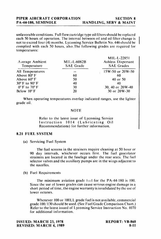
PIPER AIRCRAFT CORPORATION SECTION 8PA-44-180, SEMINOLE HANDLING, SERV & MAINT
unfavorable conditions. Full flow cartridge type oil filters should be replacedeach 50 hours of operation. The interval between oil and oil filter change isnot to exceed four (4)months. Lycoming Service Bulletin No.446should be Icomplied with each 50 hours, also.The following grades are required fortemperatures:
MIL-L-22851Average Ambient MIL-L-6082B Ashless Dispersant
Temperature SAE Grade SAE GradesAll Temperatures -- I5W-50 or 20W-50Above 80° F 60 60Above 60°F 50 40 or 5030°F to 90°F 40 40
0°F to 70°F 30 30, 40 or 20W-40Below 10°F 20 30 or 20W-30
When operating temperatures overlap indicated ranges, use the lightergrade oil.
NOTE
Refer to the latest issue of Lycoming ServiceInstruction 1014 (Lubricating OilRecommendations) for further information.
8.21 FUEL SYSTEM
(a) Servicing Fuel System
The fuel screens in the strainers require cleaning at 50 hour or90 day intervals, whichever occurs first. The fuel gascolatorstrainers are located in the fuselage under the rear seats. The fuelselector valves and the auxiliary pumps are in the wings adjacent tothe nacelles.
(b) Fuel Requirements
The minimum aviation grade lael for the PA-44-180 is 100.Since the use of lower grades can cause serious engine damage in ashort period of time, the engine warranty is invalidated by the use oflower octanes.
Whenever 100 or 100LL grade fuel is not available,commercialgrade 100/ 130 should be used. (See Fuel Grade Comparison Chart.)Refer to the latest issued of Lycoming Service Instruction No. 1070for additional information.
ISSUED: MARCH 23, 1978 REPORT: VB-860REVISED: MARCH 4, 1989 8-11
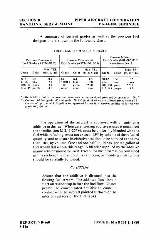
SECTION 8 PIPER AIRCRAFT CORPORATIONHANDLING, SERV & MAINT PA-44-180, SEMINOLE
A summary of current grades as well as the previous fueldesignations is shown in the following chart:
FUEL GRADE COMPARISON CHART
Current MilitaryPrevious Commercial Current Commercial Fuel Grades (Mit-G-5572El
Fuel Grades (ASTM-D910) Fuel Grades (ASTM-D910-75) Amendment No 3
Max TEL Max TEL Max TE!Grade Color mil US gal Grade Color ml/ US gal Grade Color ml/ US gal
80¡87 red 0 5 80 red 0 5 80/87 red 0 591/98 blue 20 *l00LL blue 20 none none none100/ I 30 green 3 0 100 green
**3 0 100/ I 30 green**3 0
I IS) 145 purple 4 6 none none none I IS/145 purple 4 6
*- Grade 100LL fuel in some overseas countries is currently colored green and designated as "100L "
**- Commercial fuel grade 100 and grade 100/130 (both of which are colored green) having TELcontent of up to 4 ml/ US gallon are approved for use in all engines certificated for use withgrade 100/ 130 fuel
The operation of the aircraft is approved with an anti-icingadditive in the fuel. When an anti-icing additive is used it must meetthe specification MIL-1-27686, must be uniformly blended with thefuel while refueling, must not exceed
.15%
by volume of the refueledquantity, and to ensure its effectiveness should be blended at not lessthan
.!0%
by volume. One and one half liquid ozs. per ten gallon offuel would fall within this range. A blender supplied by the additivemanufacturer should be used. Except for the information containedin this section, the manufacturer's mixing or blending instructionsshould be carefully followed.
CAUTION
Assure that the additive is directed into theflowing fuel stream The additive flow shouldstart after and stop before the fuel flow. Do notpermit the concentrated additive to come incontact with the aircraft painted surfaces or theinterior surfaces of the fuel tanks
REPORT: VB-860 ISSUED: MARCH 1, 19808-lla
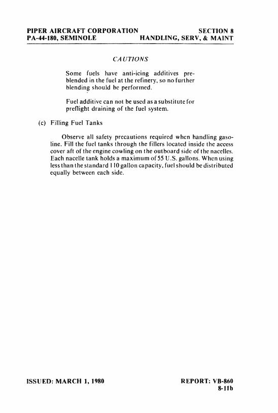
PIPER AIRCRAFT CORPORATION SECTION 8PA-44-180, SEMINOLE HANDLING, SERV, & MAINT
CAUTIONS
Some fuels have anti-icing additives pre-blended in the fuel at the refinery, so no furtherblending should be performed.
Fuel additive can not be used as a substitute forpreflight draining of the fuel system.
(c) Filling Fuel Tanks
Observe all safety precautions required when handling gaso-line. Fill the fuel tanks through the fillers located inside the accesscover aft of the engine cowling on the outboard side of the nacelles.Each nacelle tank holds a maximum of 55 U.S. gallons. When usingless than the standard I 10gallon capacity, fuel should be distributedequally between each side.
ISSUED: MARCH 1, 1980 REPORT: VB-8608-11b
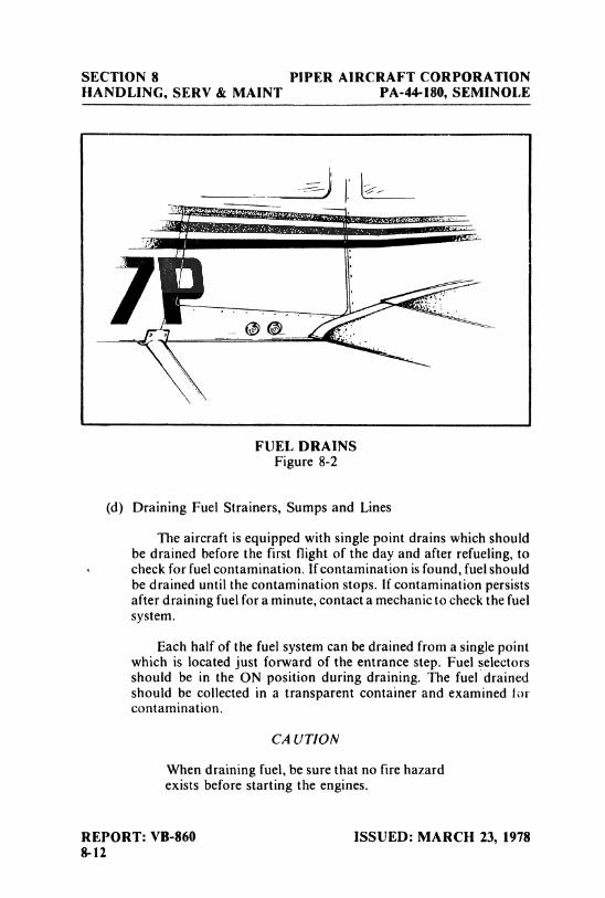
SECTION 8 PIPER AIRCRAFT CORPORATIONHANDLING, SERV & MAINT PA-44-180, SEMINOLE
FUEL DRAINSFigure 8-2
(d) Draining Fuel Strainers, Sumps and Lines
The aircraft is equipped with single point drains which shouldbe drained before the first flight of the day and after refueling, tocheck for fuelcontamination. If contamination is found, fuel shouldbe drained until the contamination stops. If contamination persistsafter draining fuel for a minute, contact a mechanic to check the fuelsystem.
Each half of the fuel system can be drained from a single pointwhich is located just forward of the entrance step. Fuel selectorsshould be in the ON position during draining. The fuel drainedshould be collected in a transparent container and examined Iorcontammation.
CAUTION
When draining fuel, be sure that no fire hazardexists before starting the engines.
REPORT: VB-860 ISSUED: MARCH 23, 19788-12
PIPER AIRCRAFT CORPORATION SECTION 8PA-44-180, SEMINOLE HANDLING, SERV & MAINT
(e) Draining Fuel System
The fuel may be drained by opening the valves at the right handside of the fuselage just forward of the entrance step or bysiphoning. The remaining fuel in the lines may be drained throughthe gascolators.
8.23 TIRE INFLATION
For maximum service from the tires, keep them inflated to the properpressures. The main gear tires should be inflated to 55 psi and the nose gearshould be inflated to 50 psi.
Interchange the tires on the main wheels, if necessary, to produce evenwear. All wheels and tires are balanced before original installation, and therelationship of the tire, tube, and wheel should be maintained if at allpossible. Unbalanced wheels can cause extreme vibration on takeoff. In theinstallation of new components, it may be necessary to rebalance the wheelwith the tire mounted.
When checking the pressure, examine the tires for wear, cuts, bruisesand slippage.
8.25 BATTERY SERVICE
Access to the 12-volt 35 ampere hour battery is gaíned through thefiberglass nose cone The battery container has a plastic drain tube which isnormally closed off. This tube should be opened occasionally to drain off
any accumulation of liquid
The battery fluid level must not be brought above the baffle plates. Itshould be checked every 30 days to determine that the fluid level is properand the connections are tight and free of corrosion. DO NOT fill the batteryabove the baffle plates. DO NOT fill the battery with acid -use distilled wateronly. A hydrometer check will determine the percent of charge in the battery.
If the battery is not properly charged, recharge it starting with a rate of 4amperes and finishing with a rate of 2 amperes. Quickcharges are notrecommended.
ISSUED: MARCH 23, 1978 REPORT: VB-8608-13
SECTION 8 PIPER AIRCRAFT CORPORATIONHANDLING, SERV & MAINT PA-44-180, SEMINOLE
The external power receptacle, if installed, is located on the left side ofthe nose section. Be sure the master switch is off while inserting orremoving a plug at this receptacle.
Refer to the Service Manual for detailed procedures for cleaning andservicing the battery.
8.27 SERIAL NUMBER PLATES
The serial number plate is located on the bottom of the fuselage near theaft end of the tail cone. The serial number should always be used whenreferring to the airplane on service or warranty matters.
8.29 LUBRICATION
Lubrication at regular intervals is an essential part of the maintenanceof an airplane. For lubrication instructions and a chart showing lubricationpoints, types of lubricants to be used, lubrication methods and recom-mended frequencies, refer to the Service Manual.
8.31 CLEANING
(a) Cleaning Engine Compartment
Before cleaning the engine compartment, place a strip of tapeon the magneto vents to prevent any solvent from entering theseunits.
(1) Place a large pan under the engine to catch waste.(2) With the engine cowling removed, spray or brush the
engine with solvent or a mixture of solvent and degreaserIn order to remove especially heavy dirt and greasedeposits, it may be necessary to brush areas that welesprayed.
CAUTION
Do not spray solvent into the alternator, vac-cuum pump, starter, air intakes, or alternate airinlets
REPORT: VB-860 ISSUED: MARCH 23, 19788-14
PIPER AIRCRAFT CORPORATION SECTION 8PA-44-180, SEMINOLE HANDLING, SERV & MAINT
(3) Allow the solvent to remain on the engine from five to tenminutes. Then rinse the engine clean with additionalsolvent and anow it to dry.
CAUTION
Do not operate the engine until excess solventhas evaporated or otherwise been removed.
(4) Remove the protective tape from the magnetos.(5) Lubricate the controls, bearing surfaces, etc., in
accordance with the Lubrication Chart in the ServiceManual.
(b) Cleaning Landing Gear
Before cleaning the landing gear, place a plastic cover or similarmaterial over the wheel and brake assembly.
(I) Place a pan under the gear to catch waste.(2) Spray or brush the gear area with solvent or a mixture of
solvent and degreaser, as desired. Where heavy grease anddirt deposits have collected, it may be necessary to brushareas that were sprayed, in order to clean them.
(3) Allow the solvent to remain on the gear from five to tenminutes. Then rinse the gear with additional solvent andallow to dry.
(4) Remove the cover from the wheel and remove the catchpan.
(5) Lubricate the gear in accordance with the LubricationChart in the Service Manual.
(6) Caution: Do not brush the micro switches.
(c) Cleaning Exterior Surfaces
The airplane should be washed with a mild soap and water.Harsh abrasives or alkaline soaps or detergents could makescratches on painted or plastic surfaces or could cause corrosion ofinetal. Cover areas where cleaning solution could cause damage. Towash the airplane, use the following procedure:
(I) Flush away loose dirt with water.(2) Apply cleaning solution with a soft cloth, a sponge or a
soft bristle brush.(3) To remove exhaust stains, allow the solution to remain on
the surface longer.
ISSUED: MARCH 23, 1978 REPORT: VB-8608-15
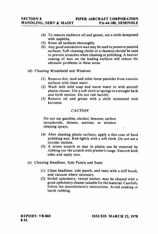
SECTION 8 PIPER AIRCRAFT CORPORATIONHANDLING, SERV & MAINT PA-44-180, SEMINOLE
(4) To remove stubborn oil and grease, use a cloth dampenedwith naphtha.
(5) Rinse all surfaces thoroughly.(6) Any good automotive wax may be used to preserve painted
surfaces. Soft cleaning cloths or a chamois should be usedto prevent scratches when cleaning or polishing. A heaviercoating of wax on the leading surfaces will reduce theabrasion problems in these areas.
(d) Cleaning Windshield and Windows
(1) Remove dirt, mud and other loose particles from exteriorsurfaces with clean water.
(2) Wash with mild soap and warm water or with aircraftplastic cleaner. Use a soft cloth or sponge in a straight backand forth motion. Do not rub harshly.
(3) Remove oil and grease with a cloth moistened withkerosene.
CAUTION
Do not use gasoline, alcohol, benzene, carbontetrachoride, thinner, acetone, or windowcleaning sprays.
(4) After cleaning plastic surfaces, apply a thin coat of hardpolishing wax. Rub lightly with a soft cloth. Do not use acircular motion.
(5) A severe scratch or mar in plastic can be removed byrubbing out the scratch with jeweler'srouge. Smooth bothsides and apply wax.
(e) Cleaning Headliner, Side Panels and Seats
(1) Clean headliner, side panels, and seats with a stiff brush,and vacuum where necessary.
(2) Soiled upholstery, except leather, may be cleaned with agood upholstery cleaner suitable for the material. Carefullyfollow the manufacturer's instructions. Avoid soaking orharsh rubbing.
REPORT: VB-860 ISSUED: MARCH 23, 19788-16
PIPER AIRCRAFT CORPORATION SECTION 8PA-44-180, SEMINOLE HANDLING, SERV & MAINT
CAUTION
Solvent cleaners require adequate ventilation.
(3) Leather should be cleaned with saddle soap or a mild handsoap and water.
(f) Cleaning Carpets
To clean carpets, first remove loose dirt with a whisk broom orvacuum. For soiled spots and stubborn stains use a noninflammabledry cleaning fluid. Floor carpets may be removed and cleaned likeany household carpet.
8.33 WINTERIZATION
For winter operation a winterization kit is installed on the inlet openingof the oil cooler outboard chamber of the plenum chamber. This kit shouldbe installed whenever the ambient temperature is 50°F or less. When the kitis not being used it can be stowed in the nose cone compartment.
ISSUED: MARCH 23, 1978 REPORT: VB-8608-17

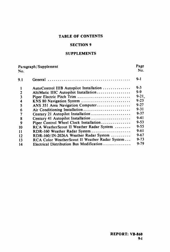
TABLE OF CONTENTS
SECTION 9
SUPPLEMENTS
Paragraph/Supplement PageNo. No.
9.1 General .......................................... 9-1
1 AutoControl IIIB Autopilot Installation .............. 9-32 AltiMatic IIIC Autopilot Installation................. 9-93 Piper Electric Pitch Trim ........................... 9-21.4 KNS 80 Navigation System . . . . . . . . . . . . . . . . . . . . . . . . . 9-235 ANS 35 I Area Navigation Computer . . . . . . . . . . . . . . . . . 9-276 Air Conditioning Installation........................ 9-317 Century 21 Autopilot Installation . . . . . . . . . . . . . . . . . . . . 9-378 Century 41 Autopilot Installation .................... 9-419 Piper Control Wheel Clock Installation . . . . . . . . . . . . . . . 9-53
10 RCA Weather Scout 11 Weather Radar System . . . . . . . . 9-5511 RDR-160 Weather Radar System.................... 9-6112 RDR-160/ IN-2026A Weather Radar System . . . . . . . . . . 9-6713 RCA Color WeatherScout II Weather Radar System... 9-7314 Electrical Distribution Bus Modification . . . . . . . . . . . . . . 9-79
REPORT: VB-8609-i

PIPER AIRCRAFT CORPORATION SECTION 9PA-44-180, SEMINOLE SUPPLEMENTS
SECTION 9
SUPPLEMENTS
9.1 GENERAL
This section provides information in the form of supplements which arenecessary for efficient operation of the airplane when it is equipped with oneor more of the various optional systems and equipment not approved withthe standard airplane.
All of the supplements provided in this section are "FAA Approved"and consecutively numbered as a permanent part of this handbook. Theinformation contained in each supplement applies only when the relatedequipment is installed in the airplane.
ISSUED: MARCH 23, 1978 REPORT: VB-8609-1
SECTION 9 PIPER AIRCRAFT CORPORATIONSUPPLEMENTS PA-44-180, SEMINOLE
THIS PAGE INTENTIONALLY LEFT BLANK
REPORT: VB-860 ISSUED: MARCH 23, 19789-2
PIPER AIRCRAFT CORPORATION SECTION 9PA-44-180, SEMINOLE SUPPLEMENTS
SUPPLEMENT 1
AUTOCONTROL IIIB AUTOPILOT INSTALLATION
SECTION 1 - GENERAL
This supplement supplies information necessary for the operation of theairplane when the optional Piper AutoControl IIIB Autopilot is installed.The information contained within this supplement is to be used inconjunction with the complete handbook.
This supplement has been "FAA Approved"as a permanent part of thishandbook based on EDO-AIRE Mitchell STC SA3276SW-D and mustremain in this handbook at all times when the optional Piper AutoControlIIIB Autopilot is installed.
SECTION 2 - LIMITATIONS
(a) Autopilot operation prohibited above 185 KIAS. (Autopilot Vmo)(b) Autopilot must be "OFF" for takeoff and landing.
SECTION 3 - EMERGENCY PROCEDURES
(a) In an emergency the AutoControl IIIB can be disconnected bypushing the AP ON-OFF switch "OFF."
(b) The autopilot can be overpowered at either control wheel.(c) An autopilot runaway, with a 3 second delay in the initiation of re-
covery while operating in climb, cruise or descending flight, couldresult in a 58° bank and 190 foot altitude loss. Maximum altitudeloss measured at 185 KIAS in descent.
(d) An autopilot runaway, with a 1second delay in the initiation of re-covery during an approach operation, single or multi-engine,coupied or uncoupled, could result in a 12° bank and 20 foot alti-tude loss.
ISSUED: MARCH 23, 1978 REPORT: VB-8609-3
SECTION 9 PIPER AIRCRAFT CORPORATIONSUPPLEMENTS PA-44-180, SEMINOLE
(e) Emergency operation with optional NSD 360A (HSI) - Slavedand/or Non-Slaved:
NSD 360A(1) Appearance of HDG Flag:
a. Check air supply gauge (vacor pressure) for adequate airsupply (4 in. Hg. min.).
b. Check compass circuit breaker.c. Observe display for proper operation.
(2) To disable heading card - pull circuit breaker and use magneticcompass for directional data.
NOTE
If heading card is not operational, autopilotshould not be used.
(3) With card disabled, VOR/ Localizer and Glide Slope displaysare still functional; use card set to rotate card to aircraft head-ing for correct picture.
(4) Slaving Failure - (i.e. failure to self-correct for gyro drift):a. Check gyro slaving switch is set to No. I position.b. Check for HDG Flag.c. Check compass circuit breaker.d. Reset heading card while observing slaving meter.
NOTE
Dead slaving meter needle or needle displacedfully one direction indicates a slaving systemfailure.
e. Select slaving amplifier No. 2 (gyroslaving switch is set toNo. 2 position).
f. Reset heading card while checking slaving meter.g. Switch to free gyro mode and periodically set card as
unslaved gyro.
NOTE
In the localizer mode the "TO-FROM" arrowsmay remain out of view, depending upon thedesign of the NAV converter used in theinstallation.
REPORT: VB-860 ISSUED: MARCH 23, 19789-4
PIPER AIRCRAFT CORPORATION SECTION 9PA-44-180, SEMINOLE SUPPLEMENTS
SECTION 4 - NORMAL PROCEDURES
PREFLIGHT
(a) AUTOPILOT(1) Place radio coupler in HDG mode (ifinstalled) and place the
AP "ON-OFF" switch to the "ON" position to engage rollsection. Rotate roll command knob left and right and observethat control whe¢\ describes a corresponding left and right turn,then center knob.
(2) Set proper D.G. heading on D.G. and turn HDG bug to aircraftheading. Engage HDG mode rocker switch and rotate 11DGbug right and left. Aircraft control wheel should turn samedirection as bug. Grasp control wheel and manually overrideservo, both directions.
(b) RADIO COUPLER - (OPTIONAL)(1) Tune and identify VOR or VOT station. Position radiocoupler
to OMNI mode. Place autopilot and HDG switches to the ONposition. Set HDG bug to aircraft heading and rotate OBS tocause OMNI indicator needle to swing left and right slowly.Observe that control wheel rotates in direction of needlemovement.
(2) Disengage AP "ON-OFF" switch. Reset radio coupler controlto HDG.
IN-FLIGHT
(a) Trim airplane (ballcentered).
(b) Check air pressure or vacuum to ascertain that the directional gyroand attitude gyro are receiving sufficient air.
ISSUED: MARCH 23, 1978 REPORT: VB-8609-5
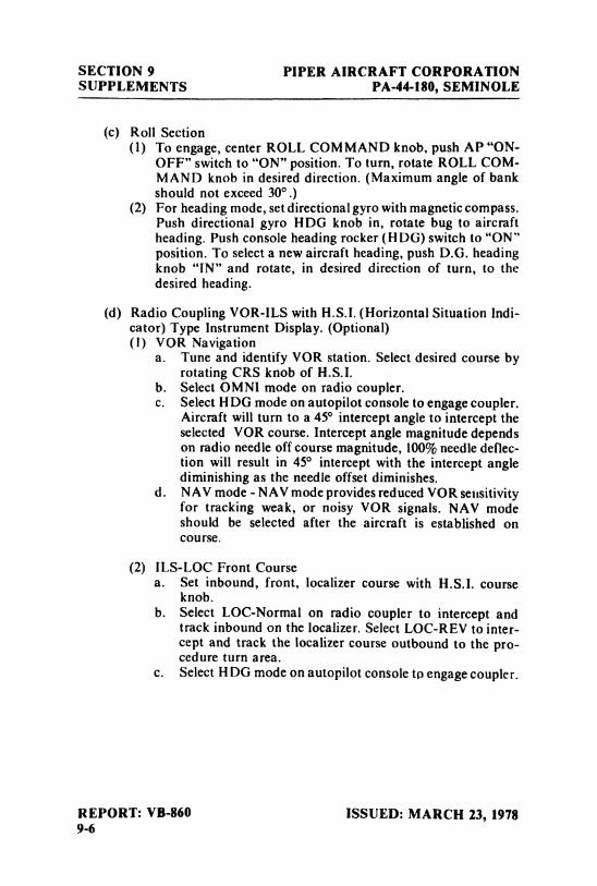
SECTION 9 PIPER AIRCRAFT CORPORATIONSUPPLEMENTS PA-44-180, SEMINOLE
(c) Roll Section(1) To engage, center ROLL COMMAND knob, push AP"ON-
OFF" switch to "ON" position. To turn, rotate ROLL COM-MAND knob in desired direction. (Maximum angle of bankshould not exceed 30°.)
(2) For heading mode, set directional gyro with magnetic compass.Push directional gyro HDG knob in, rotate bug to aircraftheading. Push console heading rocker (HDG) switch to "ON"position. To select a new aircraft heading, push D.G. headingknob "IN" and rotate, in desired direction of turn, to thedesired heading.
(d) Radio Coupling VOR-ILS with H.S.I. (Horizontal Situation Indi-cator) Type Instrument Display. (Optional)(1) VOR Navigation
a. Tune and identify VOR station. Select desired course byrotating CRS knob of H.S.I.
b. Select OMNI mode on radio coupler.c. Select HDG mode on autopilot console to engage coupler.
Aircraft will turn to a 45° intercept angle to intercept theselected VOR course. Intercept angle magnitude dependson radio needle off course magnitude, 100% needle deflec-tion will result in 45° intercept with the intercept anglediminishing as the needle offset diminishes.
d. NAV mode -NAV mode provides reduced VOR sensitivityfor tracking weak, or noisy VOR signals. NAV modeshould be selected after the aircraft is established oncourse.
(2) ILS-LOC Front Coursea. Set inbound, front, localizer course with H.S.I. course
knob.b. Select LOC-Normal on radio coupler to intercept and
track inbound on the localizer. Select LOC-REV to inter-cept and track the localizer course outbound to the pro-cedure turn area.
c. Select H DG mode on autopilot console to engage coupler.
REPORT: VB-860 ISSUED: MARCH 23, 19789-6
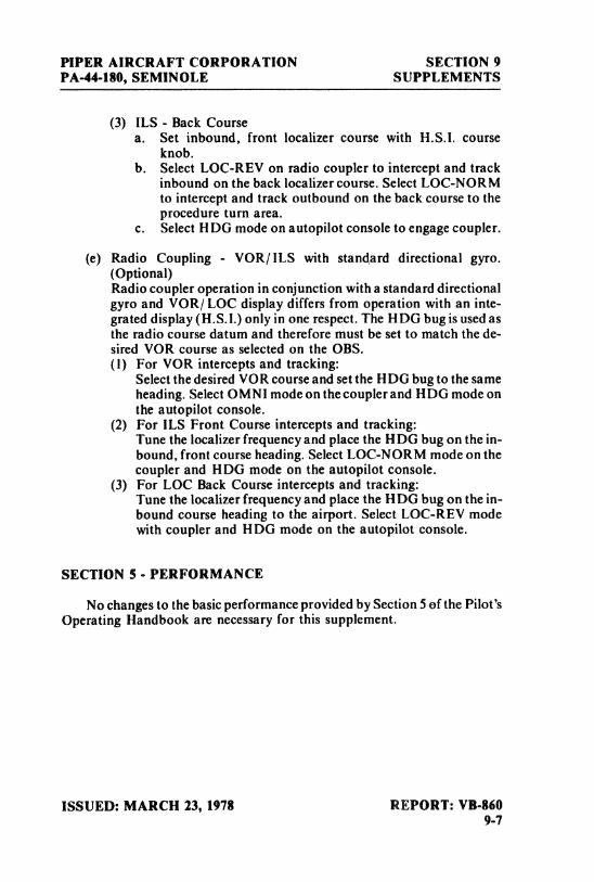
PIPER AIRCRAFT CORPORATION SECTION 9PA-44-180, SEMINOLE SUPPLEMENTS
(3) ILS - Back Coursea. Set inbound, front localizer course with H.S.I. course
knob.b. Select LOC-REV on radio coupler to intercept and track
inbound on the back localizer course. Select LOC-NOR Mto intercept and track outbound on the back course to theprocedure turn area.
c. Select HDG mode on autopilot console to engage coupler.
(e) Radio Coupling - VOR/ ILS with standard directional gyro.(Optional)Radio coupler operation in conjunction with a standard directionalgyro and VOR/ LOC display differs from operation with an inte-grated display (H.S.I.) only in one respect. The HDG bug is used asthe radio course datum and therefore must be set to match the de-sired VOR course as selected on the OBS.(1) For VOR intercepts and tracking:
Select the desired VOR course and set the HDG bug to the sameheading.SelectOMN1modeonthecouplerandHDGmodeonthe autopilot console.
(2) For ILS Front Course intercepts and tracking:Tune the localizer frequency and place the HDG bug on the in-bound, front course heading. Select LOC-NORM mode on thecoupler and HDG mode on the autopilot console.
(3) For LOC Back Course intercepts and tracking:Tune the localizer frequency and place the HDG bug on the in-bound course heading to the airport. Select LOC-REV modewith coupler and HDG mode on the autopilot console.
SECTION 5 - PERFORMANCE
No changes to the basic performance provided by Section 5 ef the Pilot'sOperating Handbook are necessary for this supplement.
ISSUED: MARCH 23, 1978 REPORT: VB-8609-7
SECTION 9 PIPER AIRCRAFT CORPORATIONSUPPLEMENTS PA-44-180, SEMINOLE
THIS PAGE INTENTIONALLY LEFT BLANK
REPORT: VB-860 ISSUED: MARCH 23, 19789-8
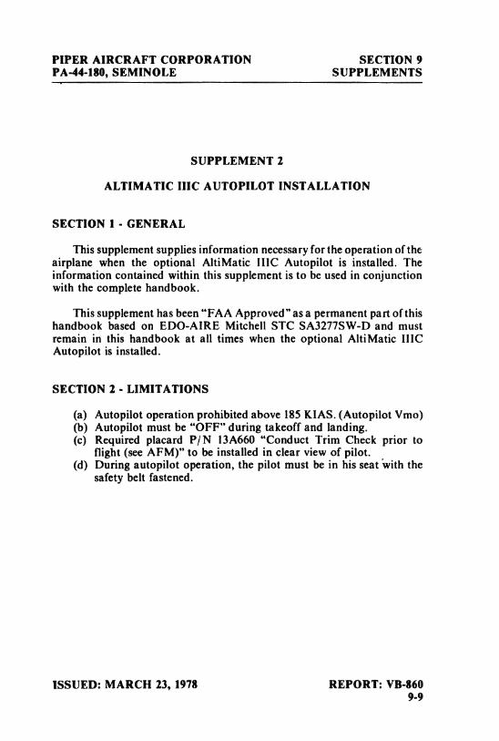
PIPER AIRCRAFT CORPORATION SECTION 9PA-44-180, SEMINOLE SUPPLEMENTS
SUPPLEMENT 2
ALTIMATIC IIIC AUTOPILOT INSTALLATION
SECTION 1 - GENERAL
This supplement supplies information necessary for the operation of theairplane when the optional AltiMatic IIIC Autopilot is installed. Theinformation contained within this supplement is to be used in conjunctionwith the complete handbook.
This supplement has been "FAA Approved" as a permanent part of thishandbook based on EDO-AIRE Mitchell STC SA3277SW-D and mustremain in this handbook at all times when the optional AltiMatic IIICAutopilot is installed.
SECTION 2 - LIMITATIONS
(a) Autopilot operation prohibited above 185 KIAS. (Autopilot Vmo)(b) Autopilot must be "OFF" during takeoff and landing.(c) Required placard P/ N 13A660 "Conduct Trim Check prior to
flight (seeAFM)" to be installed in clear view of pilot.(d) During autopilot operation, the pilot must be in his seat with the
safety belt fastened.
ISSUED: MARCH 23, 1978 REPORT: VB-8609-9
SECTION 9 PIPER AIRCRAFT CORPORATIONSUPPLEMENTS PA-44-180, SEMINOLE
SECTION 3 - EMERGENCY PROCEDURES
This aircraft is equipped with a Master Disconnect/ Interrupt Switch onthe pilot's control wheel. When the switch button is depressed it willdisconnect the autopilot. When depressed and held it will interrupt allElectric Elevator Trim Operations. Trim operations will be restored whenthe switch is released. If an autopilot or trim emergency is encountered, donot attempt to determine which system is at fault. Immediately depress andhold the Master Disconnect/ Interrupt button. Turn off autopilot and trimmaster switch and retrim aircraft, then release the interrupt switch.
NOTE
During examination of this supplement, thepilot is advised to locate and identify theautopilot controls, the trim master switch andcircuit breaker for both systems.
(a) In the event of an autopilot malfunction the autopilot can be:(I) Overpowered at either control wheel.
CAUTION
Do not overpower autopilot pitch axis forperiods longer than 3 seconds because theautotrim system will operate in a direction tooppose the pilot and will, thereby, cause anincrease in the pitch overpower forces.
(2) Disconnected by depressing the Master Disconnect/ InterruptSwitch.
(3) Disconnected by depressing the Trim Switch "AP OFF" bar.(4) Disconnected by pushing the roll rocker switch "OFF."
REPORT: VB-860 ISSUED: MARCH 23, 19789-10
PIPER AIRCRAFT CORPORATION SECTION 9PA-44-180, SEMINOLE SUPPLEMENTS
(b) In the event of a trim malfunction:(1) Depress and hold the Master Trim Interrupt Switch.(2) Trim Master Switch - "OFF." Retrim aircraft as necessary
using manual trim system.(3) Release Master Interrupt Switch - be alert for possible trim
action.(4) Trim Circuit Breaker - Pull. Do not operate trim until problem
is corrected.(5) If the trim system operates only in one direction, pull the circuit
breaker and do not operate the trim system until correctiveaction is taken. Monitor autopilot operation closely whenoperating without trim follow-up.
(c) If a trim runaway occurs with the autopilot operating, the aboveprocedure will disconnect the autopilot which will immediately re-sult in higher control wheel forces. Be prepared to manually retrim,
as necessary to eliminate undesirable forces.
(d) Altitude Loss During Malfunction:(1) An autopilot malfunction during climb, cruise or descent with
a 3 second delay in recovery initiation could result in as much as58° of bank and 300' of altitude loss. Maximum altitude lossmeasured in a descent at Vmo.
(2) An autopilot malfunction during an approach with a 1 seconddelay in recovery initiation could result in as much as 12° ofbank and 60'altitude loss. Maximum altitude loss measured inapproach configuration gear down and operating either cou-pied or uncoupled, single or multi<ngine.
(e) Emergency Operation With Optional NSD 360A (HSI) - Slavedand/or Non-Slaved:
NSD 360A(1) Appearance of HDG Flag:
a. Check air supply gauge (vacor pressure) for adequate airsupply (4in. Hg. min.).
b. Check compass circuit breaker.c. Observe display for proper operation.
ISSUED: MARCH 23, 1978 REPORT: VB-8609-11
SECTION 9 PIPER AIRCRAFT CORPORATIONSUPPLEMENTS PA-44-180, SEMINOLE
(2) To disable heading card - pull circuit breaker and use magneticcompass for directional data.
NOTE
If heading card is not operational, autopilotshould not be used.
(3) With card disabled, VOR/ Localizer and Glide Slope displaysare still functional; use card set to rotate card to aircraft head-ing for correct picture.
(4) Slaving Failure - (i.e.failure to self-correct for gyro drift):a. Check gyro slaving switch is set to No. I position.b. Check for HDG Flag.c. Check compass circuit breaker,d. Reset heading card while observing slaving meter.
NOTE
Dead slaving meter needle or a needle displacedfully one direction indicates a slaving systemfailure.
e. Select slaving amplifier No. 2 (gyroslaving switch is set toNo. 2 position).
f. Reset heading card while checking slaving meter.g. Switch to free gyro and periodically set card as unslaved
gyro.
NOTE
In the localizer mode the "TO-FROM"arrowsmay remain out of view, depending upon thedesign of the NAV converter used in theinstallation.
REPORT: VB-860 ISSUED: MARCH 23, 19789-12
PIPER AIRCRAFT CORPORATION SECTION 9PA-44-180, SEMINOLE SUPPLEMENTS
(f) Single Engine Operations:(1) Engine failure during an autopilot approach operation: Dis-
engage autopilot; conduct remainder of approach manually.(2) Engine failure during go-around: Disengage autopilot, retrim
aircraft, perform normal aircraft engine out procedures; thenre-engage autopilot.
(3) Engine failure during normal climb, cruise, descent: Retrimaircraft, perform normal aircraft engine out procedures.
(4) Maintain aircraft yaw trim throughout all single engine opera-tions.
SECTION 4 - NORMAL PROCEDURES
PREFLIGHT INSPECTION - AUTOPILOT
(a) Roll Section(!) Place Radio Coupler in "Heading" mode and place roll rocker
switch "ON" to engage roll section. Rotate roll command knobleft and right and observe that control wheel describes a corre-sponding left and right turn, then center knob.
(2) Set proper D.G. Heading on D.G. and turn Heading Bug to air-craft heading. Engage "Heading" mode rocker switch and ro-tate heading bug right and left. Aircraft control wheel shouldturn same direction as bug. Grasp control wheel and manuallyoverride servo, both directions.
(3) Disengage autopilot by depressing trim switch. Check aileronoperation is free and autopilot is disconnected from controls.
(b) Pitch Section(1) Engage "Roll" rocker switch.(2) Center pitch command disc and engage "Pitch"rocker switch.(3) Rotate pitch command disc full UP and full DOWN and check
that control wheel moves same direction. Check to see thatservo can be overriden by hand at control wheel.
NOTE
Autopilot might not be able to raise elevators,on ground, without assistance from pilot.
ISSUED: MARCH 23, 1978 REPORT: VB-8609-13
SECTION 9 PIPER AIRCRAFT CORPORATIONSUPPLEMENTS PA-44-180, SEMINOLE
(4) Hold control wheel and disengage autopilot by pressing MasterAutopilot Disconnect/Trim Interrupt Switch button. CheckRoll and Pitch controls to assure autopilot has disconnected.
TRIM SYSTEM
GeneralThis aircraft is equipped with a Command Trim System designed towithstand any type of single malfunction, either mechanical orelectrical, without uncontrolled operation resulting. The preflightcheck procedure is designed to uncover hidden failures that mightotherwise go undetected. Proper operation of the electric trimsystem is predicated on conducting the following preflight checkbefore each flight. If the trim system fails any portion of the pro-cedure, pull the trim circuit breaker out until trim system is re-paired. Substitution of any trim system component for anothermodel is not authorized. For emergency interrupt information,refer to Section 3 of this Supplement.
Command Electric Trim SwitchThe Command Electric Trim Switch on the left hand portion of thepilot's control wheel has two functions:(1) When the top bar (AP OFF) is pressed, it disconnects the
Autopilot.(2) When the top bar is pressed AND the rockeris moved forward,
nose down trim will occur, when moved aft, nose up trim willoccur.
(a) Preflight: Command Trim - Before Each Flight(!) Check trim circuit breaker - IN.(2) Trim Master Switch - ON.(3) AP OFF - Check normal trim operation - UP. Grasp trim wheel
and check override capability. Check nose down operation. Re-check override.
(4) With trim operating - depress interrupt switch - trim shouldstop - release interrupt switch - trim should operate.
(5) Activate center bar only. Push rocker fore and aft only. Trimshould not operate with either separate action.
REPORT: VB-860 ISSUED: MARCH 23, 19789-14
PIPER AIRCRAFT CORPORATION SECTION 9PA-44-180, SEMINOLE SUPPLEMENTS
(b) Autotrim - Before Each Flight(1) AP ON - (Roll and Pitch Sections) Check automatic operation
by activating autopilot pitch command UP then DN. Observetrim operation follows pitch command direction.
NOTE
In autopilot mode, there will be approximatelya 3 second delay between operation of pitchcommand and operation of trim.
(2) Press center bar (AP OFF) - release - check autopilot dis-engagement.
(3) Rotate trim wheel to check manual trim operation. Reset totakeoff position prior to takeoff.
AUTOPILOT IN-FLIGHT PROCEDURE
(a) Trim airplane (ballcentered).
(b) Check air pressure or vacuum to ascertain that the directional gyroand attitude gyro are receiving sufficient air.
(c) Roll Section(I) To engage - Center ROLL COMMAND knob, push ROLL
rocker to "ON" position. To turn, rotate console ROLL knobin desired direction.
(2) For heading mode, set directional gyro with magnetic compass.Push directional gyro HDG knob in, rotate to select desiredheading. Push console heading rocker (HDG) to "ON" posi-tion. (Maximum angle to bank will be 20° with heading lockengaged.)
(d) Pitch Section (Roll section must be engaged prior to pitch sectionengagement).(!) Center pitch trim indicator with the pitch command disc.(2) Engage pitch rocker switch. To change attitude, rotate pitch
command disc in the desired direction.
ISSUED: MARCH 23, 1978 REPORT: VB-8609-15
SECTION 9 PIPER AIRCRAFT CORPORATIONSUPPLEMENTS PA-44-180, SEMINOLE
(e) Altitude HoldUpon reaching desired or cruising altitude, engage altitude holdmode rocker switch. As long as Altitude Hold mode rocker is en-gaged, aircraft will maintain selected altitude. For maximum pas-senger comfort, rate of climb or descent should be reduced to ap-proximately 500 FPM prior to altitude hold engagement. Foraccurate Altitude Holding below 90 KIAS lower flaps orie or twonotches.
NOTE
Prior to disengaging Altitude Hold mode,rotate Pitch Command Disc to center.
(f) Radio Coupling VOR-ILS with H.S.I. type instrument display.(Optional)(1) VOR Navigation
a. Tune and identify VOR Station. Select desired course byrotating CRS knob of H.S.I.
b. Select OMNI mode on Radio Coupler.c. Select HDG mode on autopilot console to engage coupler.
Aircraft will turn to a 45° intercept angle to intercept theselected VOR course. Intercept angle magnitude dependson radio needle off - course magnitude, 100% needle de-flection will result in 45° intercept angle, diminishing asthe needle off-set diminishes.
d. NAV mode - NAV mode provides reduced VOR sensitivityfor tracking weak, or noisy, VOR signals. NAV modeshould be selected after the aircraft is established oncourse.
(2) ILS-LOC Front Coursea. Set inbound, front, localizer course with H.S.I. course
knob.b. Select LOC-Normal on Radio Coupler to intercept and
track inbound on the localizer. Select LOC-REV to inter-cept and track the localizercourse outbound to procedureturn area.
c. Select HDG mode on autopilot console to engage coupler.
REPORT: VB-860 ISSUED: MARCH 23, 19789-16
PIPER AIRCRAFT CORPORATION SECTION 9PA-44-180, SEMINOLE SUPPLEMENTS
(3) ILS - Back Coursea. Set inbound, front, localizer course with H.S.I. course
knob.b. Select LOC-REV, on radio coupler to intercept and track
inbound on the back localizer course. Select LOC-NORMto intercept and track outbound on the back course to theprocedure turn area.
c. Engage HDG mode on autopilot console to engage cou-pler.
(g) Radio Coupling - VOR/ ILS with standard directional gyro.(Optional)Radio Coupler operation in conjunction with a standard directionalgyro and VOR/ LOC display differs from operation with an in-tegrated display (H.S.I.) only in one respect. The HDG bug is usedas the radio course datum and therefore must be set to match the de-sired VOR/ ILS course as selected on the O.B.S.(1) For VOR Intercepts and Tracking:
Select the desired VOR Course and set the HDG bug to thesame heading. Select OMNI mode on the coupler and engageHDG mode on the autopilot console.
(2) For ILS Front Course Intercepts and Tracking:Tune the localizer frequency and place the HDG bug on theinbound, front course heading. Select LOC-NORM mode onthe coupler and engage HDG mode on the autopilot console.
(3) For LOC Back Course Intercepts and Tracking:Tune the localizer frequency and place the HDG bug on theinbound course heading to the airport. Select LOC-REV mode
on the coupler and engage HDG mode on the autopilotconsole.
(h) Coupled Approach Operations(1) VOR or LOC
a. After arrival at the VOR Station, track outbound to theprocedure turn area as described in Section 4 (f) or (g)asappropriate. Slow to 110 KIAS and lower one notch offlaps.
b. Use HDG mode and Pitch or Altitude Hold modes asappropriate during procedure turn.
ISSUED: MARCH 23, 1978 REPORT: VB-8609-17
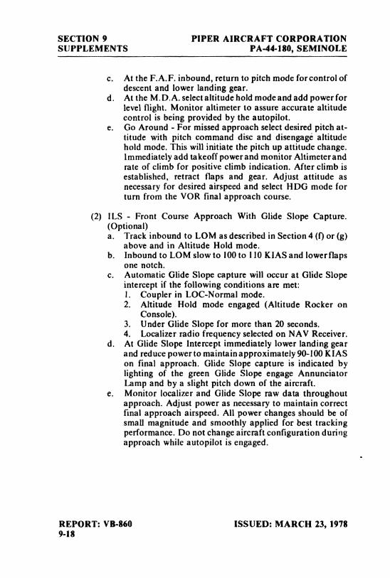
SECTION 9 PIPER AIRCRAFT CORPORATIONSUPPLEMENTS PA-44-180, SEMINOLE
c. At the F.A.F. inbound, return to pitch mode for control ofdescent and lower landing gear.
d. At the M.D.A. select altitude hold mode and add power forlevel flight. Monitor altimeter to assure accurate altitudecontrol is being provided by the autopilot.
e. Go Around - For missed approach select desired pitch at-titude with pitch command disc and disengage altitudehold mode. This will initiate the pitch up attitude change.Immediately add takeoff powerand monitor Altimeter andrate of climb for positive climb indication. After climb isestablished, retract flaps and gear. Adjust attitude asnecessary for desired airspeed and select HDG mode forturn from the VOR final approach course.
(2) ILS - Front Course Approach With Glide Slope Capture.(Optional)a. Track inbound to LOM as described in Section 4 (f)or (g)
above and in Altitude Hold mode.b. Inbound to LOM slow to 100 to I10 KIAS and lowerflaps
one notch.c. Automatic Glide Slope capture will occur at Glide Slope
intercept if the following conditions an met:1. Coupler in LOC-Normal mode.2. Altitude Hold mode engaged (Altitude Rocker on
Console).3. Under Glide Slope for more than 20 seconds.4. Localizer radio frequency selected on NAV Receiver.
d. At Glide Slope Intercept immediately lower landing gearand reduce power to maintain approximately 90-100 KIASon final approach. Glide Slope capture is indicated bylighting of the green Glide Slope engage AnnunciatorLamp and by a slight pitch down of the aircraft.
e. Monitor localizer and Glide Slope raw data throughoutapproach. Adjust power as necessary to maintain correctfinal approach airspeed. All power changes should be ofsmall magnitude and smoothly applied for best trackingperformance. Do not change aircraft configuration duringapproach while autopilot is engaged.
REPORT: VB-860 ISSUED: MARCH 23, 19789-18
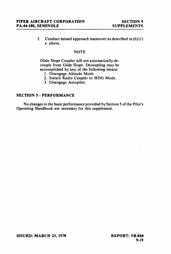
PIPER AIRCRAFT CORPORATION SECTION 9PA-44-180, SEMINOLE SUPPLEMENTS
f. Conduct missed approach maneuver as described in (h)(I)e. above.
NOTE
Glide Slope Coupler will not automatically de-couple from Glide Slope. Decoupling may beaccomplished by any of the following means:
I. Disengage Altitude Mode.2. Switch Radio Coupler to HDG Mode.3. Disengage Autopilot.
SECTION 5 - PERFORMANCE
No changes to the basic performance provided by Section 5 of the Pilot'sOperating Handbook are necessary for this supplement.
ISSUED: MARCH 23, 1978 REPORT: VB-8609-19

SECTION 9 PIPER AIRCRAFT CORPORATIONSUPPLEMENTS PA-44-180, SEMINOLE
THIS PAGE INTENTIONALLY LEFT BLANK
REPORT: VB-860 ISSUED: MARCH 23, 19789-20
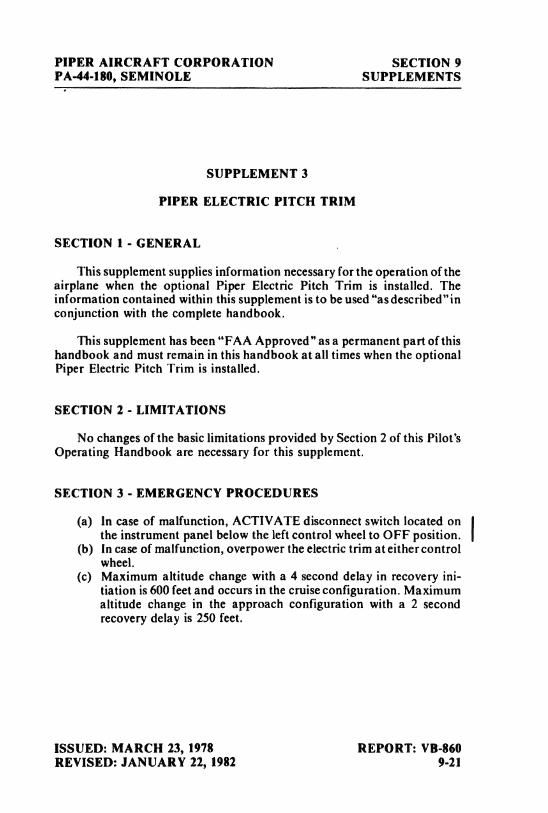
PIPER AIRCRAFT CORPORATION SECTION 9PA-44-180, SEMINOLE SUPPLEMENTS
SUPPLEMENT 3
PIPER ELECTRIC PITCH TRIM
SECTION 1 - GENERAL
This supplement supplies information necessary for the operation of theairplane when the optional Piper Electric Pitch Trim is installed. Theinformation contained within this supplement is to be used "asdescribed"inconjunction with the complete handbook.
This supplement has been "FAA Approved"as a permanent part of thishandbook and must remain in this handbook at all times when the optionalPiper Electric Pitch Trim is installed.
SECTION 2 - LIMITATIONS
No changes of the basic limitations provided by Section 2 of this Pilot'sOperating Handbook are necessary for this supplement.
SECTION 3 - EMERGENCY PROCEDURES
(a) In case of malfunction, ACTIVATE disconnect switch located onthe instrument panel below the left control wheel to OFF position.
(b) In case of malfunction, overpower the electric trim ateithercontrolwheel.
(c) Maximum altitude change with a 4 second delay in recovery ini-tiation is 600 feet and occurs in the cruise configuration. Maximumaltitude change in the approach configuration with a 2 secondrecovery delay is 250 feet.
ISSUED: MARCH 23, 1978 REPORT: VB-860REVISED: JANUARY 22, 1982 9-21
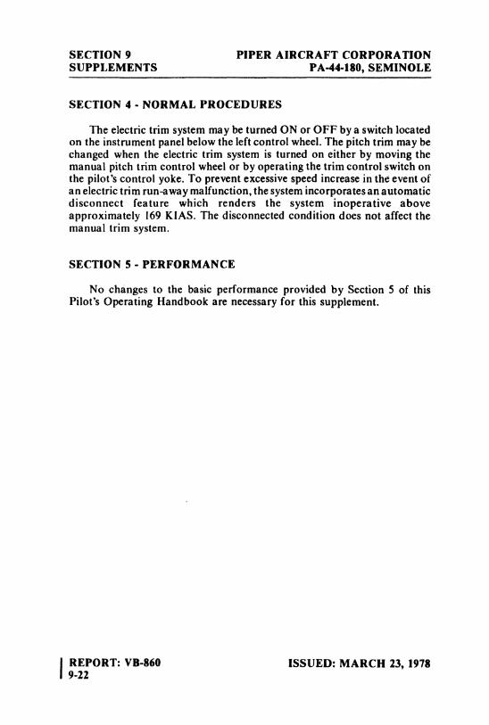
SECTION 9 PIPER AIRCRAFT CORPORATIONSUPPLEMENTS PA-44-180, SEMINOLE
SECTION 4 - NORMAL PROCEDURES
The electric trim system may be turned ON or OFF by a switch locatedon the instrument panel below the left control wheel. The pitch trim may bechanged when the electric trim system is turned on either by moving themanual pitch trim control wheel or by operating the trim control switch onthe pilot's control yoke. To prevent excessive speed increase in the event ofan electric trim run,9way malfunction, the system incorporates an automaticdisconnect feature which renders the system inoperative aboveapproximately 169 KIAS. The disconnected condition does not affect themanual trim system.
SECTION 5 - PERFORMANCE
No changes to the basic performance provided by Section 5 of thisPilot's Operating Handbook are necessary for this supplement.
IREPORT: VB-860 ISSUED: MARCH 23, 19789-22
PIPER AIRCRAFT CORPORATION SECTION 9PA-44-180, SEMINOLE SUPPLEMENTS
SUPPLEMENT 4
KNS 80 NAVIGATION SYSTEM
SECTION 1 - GENERAL
This supplement supplies information necessary for the operation of theairplane when the optional KNS 80 Navigation System is installed. Theinformation contained within this supplement is to be used in conjunctionwith the complete handbook.
This supplement has been "FAA Approved"as a permanent part of thishandbook and must remain in this handbook at all times when the optionalKNS 80 Navigation System is installed.
SECTION 2 - LIMITATIONS
No changes to the basic limitations provided by Section 2 of this Pilot'sOperating Handbook are necessary for this supplement.
SECTION 3 - EMERGENCY PROCEDURES
No changes to basic Emergency Procedures provided by Section 3 ofthis Pilot's Operating Handbook are necessary for this supplement.
ISSUED: MARCH 1, 1980 REPORT: VB-8609-23
SECTION 9 PIPER AIRCRAFT COlIPORATIONSUPPLEMENTS PA-44-180, SEMINOLE
SECTION 4 - NORMAL PROCEDURES
(a) KNS 80 OPERATIONThe KNS 80 can be operated in any one of 3 basic modes: (a)VOR,(b) RNAV, or (c) ILS. To change from one mode to another, theappropriate pushbutton switch is pressed, except that the ILS modeis entered automatically whenever an ILS frequency is channeledin the USE waypoint. The display will annunciate the mode bylighting a message above the pushbutton. In addition to thestandard VOR and RNAVenroute(RNV ENR)modes,the KNS80has a constant course width or parallel VOR mode (VOR PAR)and an RNAV approach mode (RNV APR). To place the unit ineither of these secondary modes the VOR pushbutton or the RNAVpushbutton, as the case may be, is pushed a second time. Repetitivepushing of the VOR button will cause the system to alternatebetween the VOR and VOR PAR modes, while repetitive pushingof the RNAV button causes the system to alternate between RNVENR and RNV APR modes.
(b) CONTROLS(1) VOR BUTTON
Momentary pushbutton.When pushed while system is in either RNV mode causessystem to go to VOR mode. Otherwise the button causes systemto toggle between VOR and VOR PAR modes.
(2) RNAV BUTTONMomentary pushbutton.When pushed while system is in either VOR mode causessystem to go to RNV ENR mode. Otherwise the button causessystem to toggle between RNV ENR and RNV APR modes.
(3) HOLD BUTTONTwo position pushbutton.When in depressed position, inhibits DME from channeling toa new station when the VOR frequencyis changed. Pushing thebutton again releases the button and channels the DME to thestation paired with the VOR station.
(4) USE BUTTONMomentary pushbutton.Causes active waypoint to take on same value as displayedwaypoint and data display to go to FRQ mode.
IREPORT: VB-860 ISSUED: MARCH 1, 19809-24
PIPER AIRCRAFT CORPORATION SECTION 9PA-44-180, SEMINOLE SUPPLEMENTS
(5) DSP BUTTONMomentary pushbutton.Causes displayed waypoint to increment by I and data displayto go to frequency mode.
(6) DATA BUTTONMomentary pushbutton.Causes waypoint data display to change from FRQto RAD toDST and back to FRQ.
(7) OFF/ PULL ID CONTROLa. Rotate counterclockwise to switch off power to the
KNS 80.b. Rotate clockwise to increase audio level.c. Pull switch out to hear VOR Ident.
(8) DATA INPUT CONTROLDual concentric knobs. Center knob has "in" and "out"positions.a. Frequency Data
Outer knob varies ! MHz digit.A carryover occurs from the units to tens position.Rollover occurs from I 17 to 108, or vice versa.Center knob varies frequency in
.05
MHz steps regardlessof whether the switch is in its "in"or "out" position.
b. Radial DataOuter knob varies 10 degree digit.A carryover occurs from tens to hundreds position.A rollover to zero occurs at 360 degrees.Center knob "in" position varies 1 degree digit.Center knob "out" position varies 0.1 degree digit.
c. Distance DataOuter knob varies 10 NM digit.A carryover occurs from the tens to hundreds place.A rollover to zero occurs at 200 NM.Center knob "in" position varies i NM digit.Center knob "out" position varies 0.1 NM digit.
(9) COURSE SELECT KNOBLocated in CDI unit.Selects desired course through the VOR ground station orwaypoint.
ISSUED: MARCH 1, 1980 REPORT: VB-860REVISED: JANUARY 22, 1982 9-25
SECTION 9 PIPER AIRCRAFT CORPORATIONSUPPLEMENTS PA-44-180, SEMINOLE
SECTION 5 - PERFORMANCE
No changes to the basic performance provided by Section 5 of thisPilot's Operating Handbook are necessary for this supplement.
IREPORT: VB-860 ISSUED: MARCH I, 19809-26
PIPER AIRCRAFT CORPORATION SECTION 9PA-44-180, SEMINOLE SUPPLEMENTS
SUPPLEMENT 5
ANS 351 AREA NAVIGATION COMPUTER
SECTION I - GENERAL
This supplement supplies information necessary for the operation of theairplane when the optional ANS 35 I Area Navigation Computer is installed.The information contained within this supplement is to be used inconjunction with the complete handbook.
This supplement has been "FAA Approved" as a permanent part of thishandbook and must remain in this handbook at all times when the optionalANS 351 Area Navigation Computer is installed.
SECTION 2 - LIMITATIONS
No changes to the basic limitations provided by Section 2 of this Pilot'sOperating Handbook are necessary for this supplement.
SECTION 3 - EMERGENCY PROCEDURES
No changes to basic Emergency Procedures provided by Section 3 ofthis Pilot's Operating Handbook are necessary for this supplement.
ISSUED: MARCH 1, 1980 REPORT: VB-8609-27
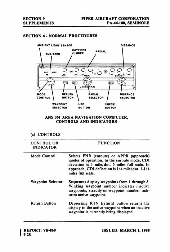
SECTION 9 PIPER AIRCRAFT CORPORATIONSUPPLEMENTS PA-44-180, SEMINOLE
SECTION 4 - NORMAL PROCEDURES
AMBIENT LIGHT SENSOR DISTANCEWAYPOINT RADIAL
ENR/APPR NUMBER
MODE RETURN RADIAL DISTANCECONTROL BUTTON SELECTOR SELECTOR
WAYPOINT USE CHECKSELECTOR BUTTON BUTTON
ANS 351 AREA NAVIGATION COMPUTER,CONTROLS AND INDICATORS
(a) CONTROLS
CONTROL OR FUNCTIONINDICATOR
Mode Control Selects ENR (enroute) or APPR (approach)modes of operation. In the enroute mode, CDIdeviation is I mile/dot, 5 miles full scale. Inapproach, CDI deflection is 1/4 mile/dot, 1-1/4miles full scale.
Waypoint Selector Sequences display waypoints from 1 through 8.Winking waypoint number indicates inactivewaypoints; steadily-on-waypoint number indi-cates active waypoint.
Return Button Depressing RTN (return)button returns thedisplay to the active waypoint when an inactivewaypoint is currently being displayed.
IREPORT: VB-860 ISSUED: MARCH 1, 19809-28
PIPER AIRCRAFT CORPORATION SECTION 9PA-44-180, SEMINOLE SUPPLEMENTS
CONTROL OR FUNCTIONINDICATOR
Use Button Depressing the USE button converts the way-point being displayed into the active waypoint.
Radial Selector Two concentric knobs set radial informationinto the display. Knobs control informationas follows:
Large knob: Changes display in 10-degreeincrements.
Small knob pushed in: Changes display 1-degree increments.
Small knob pulled out: Changes display in0.1-degree increments.
Distance Selector Two concentric knobs set distance informationin nautical miles into the display. Knobs controlinformation as follows:
Large knob: Changes display in 10-mileincrements.
Small knob pushed in: Changes display 1-mileincrements.
Small knob pulled out: Changes display in0.1-mile divisions from 00.0 through 100miles. Beyond 100 nmi, changes display in1-mile increments.
Check Button Depressing CHK (check) button causes DMEand bearing indicators to display raw distanceand bearing information. RNAV computation,CDI deviation, to/from display, and autopilottracking of RNAV path remain unaffected. Thecheck button is spring-loaded to preventpermanent actuation.
Ambient Light Automatically adjusts display lighting intensitySensor as a function of cockpit ambient light.
ISSUED: MARCH I, 1980 REPORT: VB-860 |9-29 i
SECTION 9 PIPER AIRCRAFT CORPORATIONSUPPLEMENTS PA-44-180, SEMINOLE
(b) AREA NAVIGATION WAYPOINT PROGRAMMING(1) Presentation Of Waypoint On Ground
Waypoints are entered after engine start, since the waypointinformation will probably be lost during the low-voltagecondition occurring during engine cranking. Waypoint datashould always be written in flight planning form to facilitatechecking later in flight. When power is first applied to theANS 351 and the system is in the RNAV mode, waypointnumber I will be active, (waypointnumber not blinking) andwaypoint bearing and distance preset to zero will appear.a. Waypoint number I coordinates are set into the ANS 351
using concentric knobs under bearing and distance displayfields.
b. The waypoint selection knob is then rotated to select way-point number 2. Note that the waypoint number is blink-ing, indicating that the waypoint is at this point inactive.Waypoint number 2 bearing and distance definitions amthen set into the ANS 351.
c. Set up the rest of the desired waypointsasdescribed above.d. Press the RTN (return) pushbutton to display the active
waypoint.
(2) Changing Waypoints In FlightTo change a waypoint in flight, rotate the waypoint selectoruntil the desired waypoint number and coordinates aæ dis-played on the ANS 351.a. Verify that the waypoint definition is correct by comparing
the display with the flight plan.b. Uncouple the autopilot if tracking RNAV deviation.c. Select the desired reference facility frequency on the
associated NAV receiver.d. Depress the USE pushbutton and note that the waypoint
identification number stops winking.e. Select the desired course on OBS.f. Recouple the autopilot after deviation and distance-to-
waypoint idications have stabilized.
SECTION 5 - PERFORMANCE
No changes to the basic performance provided by Section 5 of thisPilot's Operating Handbook are necessary for this supplement.
lREPORT: VB-860 ISSUED: MARCH 1, 19809-30
PIPER AIRCRAFT CORPORATION SECTION 9PA-44-180, SEMINOLE SUPPLEMENTS
SUPPLEMENT 6
AIR CONDITIONING INSTALLATION
SECTION 1 - GENERAL
This supplement supplies information necessary for the efficientoperation of the airplane when the optional air conditioning system isinstalled. The information contained within this supplement isto be used "asdescribed" in conjunction with the complete handbook.
This supplement has been "FAA Approved" as a permanent part of thishandbook and must remain in this handbook at all times when the optionalair conditioning system is installed.
The air conditioning system is a recirculating air system. The majorcomponents include an evaporator, a condenser, a compressor, a blower,switches and temperature controls.
The evaporator is located behind the rear baggage compartment. Airfrom the baggage area is drawn through the evaporator by the blower and isdistributed through an overhead duct to individual outlets located adjacentto each occupant.
The condenser is mounted aft of the evaporator on the bottom tailconeskin. A continuously operating cooling fan ducts outside air through thecondenser and dumps it overboard, on the ground or in flight, when the airconditioning is turned on.
The compressor is mounted on the front side of the left engine. It hasanelectric clutch which automatically engages or disengages the compressor toits belt drive system.
ISSUED: SEPTEMBER 26, 1980 REPORT: VB-8609-31
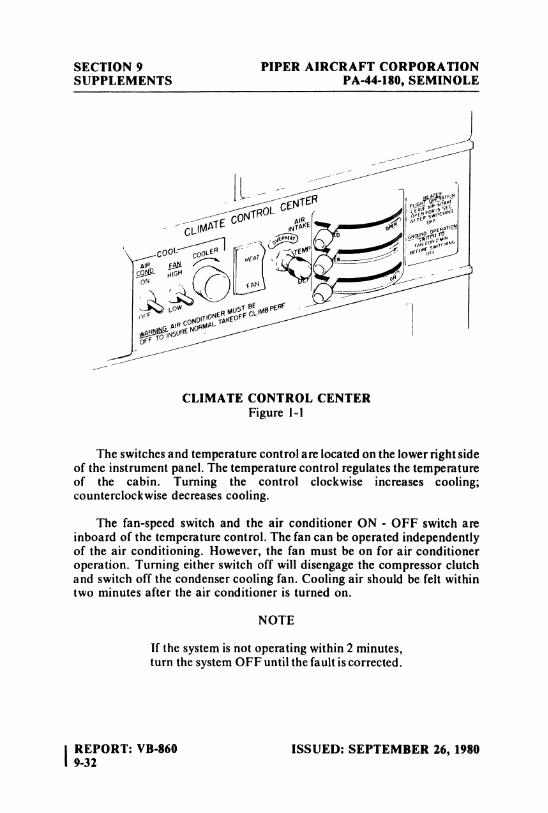
SECTION 9 PIPER AIRCRAFT CORPORATIONSUPPLEMENTS PA-44-180, SEMINOLE
CLIMATE CONTROL CENTERFigure 1-1
The switches and temperature control are located on the lower right sideof the instrument panel. The temperature control regulates the temperatureof the cabin. Turning the control clockwise increases cooling;counterclockwise decreases cooling.
The fan-speed switch and the air conditioner ON - OFF switch areinboard of the temperature control. The fan can be operated independentlyof the air conditioning. However, the fan must be on for air conditioneroperation. Turning either switch off will disengage the compressor clutchand switch off the condenser cooling fan. Cooling air should be felt withintwo minutes after the air conditioner is turned on.
NOTE
If the system is not operating within 2 minutes,turn the system OFF until the fault is corrected.
IREPORT: VB-860 ISSUED: SEPTEMBER 26, 19809-32
PIPER AIRCRAFT CORPORATION SECTION 9PA-44-180, SEMINOLE SUPPLEMENTS
The fan switch allows operation of the fan with the air conditionerturned OFF to aid in cabin air circulation. "LOW" or "HIGH" can beselected to direct a flow of air through the air conditioner outlets in theoverhead duct. These outlets can be adjusted or turned off individually.
Two circuit breakers on the circuit boaker panel protect the airconditioning electrical system.
SECTION 2 - LIMITATIONS
(a) To insure maximum climb performance the air conditioner mustbe turned "OFF" manually prior to takeoff to disengage thecompressor and turn off the condenser cooling fan. Also the airconditioner must be turned "OFF" manually before the landingapproach in preparation for a possible go-around.
(b) Placards
In full view of the pilot, in the ama of the air conditioner controlswhen the air conditioner is installed:
"WARNING: AIR CONDITIONER MUST BE OFF TOINSURE NORMAL TAKEOFF CLIMB PERFORMANCE."
SECTION 3 - EMERGENCY PROCEDURES
The air conditioner must be off during all one-engine inoperativeoperations.
No other changes to the basic Emergency Procedures provided bySection 3 of this Pilot's Operating Handbook are necessary for thissupplement.
ISSUED: SEPTEMBER 26, 1980 REPORT: VB-8609-33
SECTION 9 PIPER AIRCRAFT CORPORATIONSUPPLEMENTS PA-44-180, SEMINOLE
SECTION 4 - NORMAL PROCEDURES
Prior to takeoff, the air conditioner should be checked for properoperation as follows:
(a) Check aircraft master switch "ON."(b) Turn the air conditioner control switch to "ON"and the fan switch
to one of the operating positions. A slight decrease in left-engineRPM, and an ammeter increase of about 15 amps each, indicatesproper equipment operation. Cool air should be felt from the over-head outlets within 2 minutes.
(c) Turn the air conditioner control switch to "OFF." Left-engineRPM should increase and the ammeter indication should drop.
(d) If the system does not respond as specified above, a malfunctionis indicated and further investigation should be conducted priorto flight.
The above operational check may be performed during flight if an in-flight failure is suspected.
SECTION 5 - PERFORMANCE
Installation of the air conditioner does not effect the basic cruiseperformance information presented in Section 5 of this handbook. Theclimb performance in Section 5 is not effected when the air conditioner is inthe off position.
NOTE
To insure maximum climb performance the airconditioner must be turned off manually beforetakeoff to disengage the compressor. Also theair conditioner must be turned off manually
- before the landing approach in preparation fora possible go-around. The air conditioner mustbe off for all one-engine-inoperativeoperations.
IREPORT: VB-860 ISSUED: SEPTEMBER 26, 19809-34
PIPER AIRCRAFT CORPORATION SECTION 9PA-44-180, SEMINOLE SUPPLEMENTS
Additionally, the air conditioning system is designed so that thecompressor will declutch when the throttle is advanced to the full throttleposition to provide maximum performance should the air conditioner be inthe on position inadvertently.
ISSUED: SEPTEMBER 26, 1980 REPORT: VB-8609-35
SECTION 9 PIPER AIRCRAFT CORPORATIONSUPPLEMENTS PA-44-180, SEMINOLE
THIS PAGE INTENTIONALLY LEFT BLANK
\REPORT: VB-860 ISSUED: SEPTEMBER 26, 19809-36
PIPER AIRCRAFT CORPORATION SECTION 9PA-44-180, SEMINOLE SUPPLEMENTS
SUPPLEMENT 7
CENTURY 21 AUTOPILOT INSTALLATION
SECTION I - GENERAL
This supplement supplies information necessary for the operation of theairplane when the optional Century 21 Autopilot is installed in accordancewith STC SA3376SW-D. The information contained within this supplementis to be used in conjunction with the complete handbook.
This supplement has been "FAA Approved" as a permanent part of thishandbook and must remain in this handbook at all times when the optionalCentury 21 Autopilot is installed.
SECTION 2 - LIMITATIONS
(a) Maximum airspeed for autopilot operation is 185 KIAS.(b) Autopilot OFF during takeoff and landing.
SECTION 3 - EMERGENCY PROCEDURES
(a) AUTOPILOTIn the event of an autopilot malfunction, or anytime the autopilot isnot performing as commanded, do not attempt to identify theproblem. Regain control of the aircraft by overpowering andimmediately disconnecting the autopilot by depressing the APON-OFF switch on the programmer OFF.
Do not operate until the system failure has been identified andcorrected.
ISSUED: SEPTEMBER 26, 1980 REPORT: VB-8609-37
SECTION 9 PIPER AIRCRAFT CORPORATIONSUPPLEMENTS PA-44-180, SEMINOLE
(I) Altitude Loss During Malfunction:a. An autopilot malfunction during climb, cruise or descent
with a 3 second delay in recovery initiation could result inas mu as 59° of bank and 350'altitude loss. Maximumaltitude loss was recorded at 185 KIAS during descent.
b. An autopilot malfunction during an approach with a 1second delay in recovery initiation could result in as muchas 18° bank and 40' altitude loss. Maximum altitude lossmeasured in approach configuration, and operating eithercoupled or uncoupled, single or multi-engine.
(b) COMPASS SYSTEM(1) Emergency Operation With Optional NSD 360A (HSI) Slaved
and/or Non-Slaved:
NSD 360Aa. Appearance of HDG Flag:
1. Check air supply gauge (vacor pressure) for adequateair supply (4 in. Hg. min.).
2. Check compass circuit breaker.3. Observe display for proper operation.
b. To disable heading card - pull circuit breaker and usemagnetic compass for directional data.
NOTE
If heading card is not operational, autopilotshould not be used.
c. With card disabled VOR/ Localizer and Glide Slope dis-plays are still functional; use card set to rotate card toaircraft heading for correct picture.
d. Slaving Failure - (i.e.failure to self correct for gyro drift):1. Check gyro slaving switch is set to No. I position (if
equipped with Slave No. 1 - No. 2 switch) or "Slaved "position when equipped with Slaved and Free GyroMode Switch.
2. Check for HDG Flag.3. Check compass circuit breaker.4. Reset heading card while observing slaving meter.
IREPORT: VB-860 ISSUED: SEPTEMBER 26, 19809-38
PIPER AIRCRAFT CORPORATION SECTION 9PA-44-180, SEMINOLE SUPPLEMENTS
NOTE
Dead slaving meter needle or a needle displacedfully one direction indicates a slaving systemfailure.
5. Select slaving amplifier No. 2, if equipped.6. Reset heading card while checking slaving meter. If
proper slaving indication is not obtained, switch to freegyro mode and periodically set card as an unslavedgyro.
NOTE
In the localizer mode, the"TO-FROM"arrowsmay remain out of view, depending upon thedesign of the NAV converter used in theinstallation.
SECTION 4 - NORMAL PROCEDURES
Refer to Edo-Aire Mitchell Century 21 Autopilot Operator's Manual,PjN 688805, dated 1-79 for Autopilot Description and Normal OperatingProcedures.
(a) PREFLIGHT PROCEDURES
NOTE
During system functional check the systemmust be provided adequate D.C. voltage (12.0VDC min.) and instrument air (4.2 in. Hg.min.). It is recommended that one engine(minimum)be operated to provide thenecessary power and that the aircraft bepositioned in a level attitude, during thefunctional check.
ISSUED: SEPTEMBER 26, 1980 REPORT: VB-8609-39
SECTION 9 PIPER AIRCRAFT CORPORATIONSUPPLEMENTS PA-44-180, SEMINOLE
(b) AUTOPILOT WITH STANDARD D.G.(1) Engage autopilot.(2) Control wheel movement should correspond to HDG
command input.(3) Grasp control wheel and override roll servo actuator to assure
override capability.
(4) With HDG bug centered select NAV or APPR mode and notecontrol wheel movement toward VOR needle offset.
(5) Select REV mode and note control wheel movement oppositeVOR needle offset.
(6) Disengage autopilot.(7) Check aileron controls through full travel to assure complete
autopilot disengagement.
(c) AUTOPILOT WITH COMPASS SYSTEM (NSD 360A)(For other compass systems, refer to appropriate manufacturer'sinstructions)(1) Check slaving switch in slave or slave I or 2 position, as appro-
priate. (Slaving systems with R.M.I. output provide only slaveand free gyro positions.)
(2) Rotate card to center slaving meter - check HDG displayedwith magnetic compass HDG.
(3) Perform standard VOR receiver check.(4) Perform Steps (1) - (7) in Section 4 item (b)except in Steps (4)
and (5) substitute course arrow for HDG bug when checkingcontrol wheel movement in relation to L/ R needle. HDG bugis inoperative with NAV, APPR, or REV mode selected.
(d) IN-FLIGHT PROCEDURE(1) Trim aircraft for existing flight condition (all axes).(2) Rotate heading bug to desired heading. Engage autopilot.(3) During maneuvering flight - control aircraft through use of the
HDG bug. (HDG mode)(4) For navigation operations select modes as required by the
operation being conducted and in accordance with the modedescription provided in the Century 21 Operator's Manual.
SECTION 5 - PERFORMANCE
No changes to the basic performance provided by Section 5 of thisPilot's Operating Handbook are necessary for this supplement.
IREPORT: VB-860 ISSUED: SEPTEMBER 26, 19809-40
PIPER AIRCRAFT CORPORATION SECTION 9PA44-180, SEMINOLE SUPPLEMENTS
SUPPLEMENT 8
CENTURY 41 AUTOPILOT INSTALLATION
SECTION 1 - GENERAL
This supplement supplies information necessary for the operation of theairplane when the optional Century 41 Autopilot Model AK873 or Century41 Flight Director Autopilot Mode AK873FD is installed in accordancewith STC SA3375SW-D. The information contained within this supplementis to be used in conjunction with the complete handbook.
This supplement has been "FAA Approved"as a permanent part of thishandbook and must remain in this handbook at all times when the optionalCentury 41 Autopilot or the Century 41 Flight Director Autopilot isinstalled.
SECTION 2 - LIMITATIONS
(a) Autopilot use prohibited above 185 KIAS.(b) Autopilot OFF during takeoff and landing.(c) Required Placard, P/ N 13A990 stating "Conduct trim check prior
to first flight of day - (See A.F.M.)" to be installed in clear view ofpilot.
(d) Autopilot coupled Go-Around maneuvers prohibited [See Section4 item (i)(3)].
(e) Category I operations only.
ISSUED: SEPTEMBER 26, 1980 REPORT: VB-860REVISED: APRIL 10, 1981 941
SECTION 9 PIPER AIRCRAFT CORPORATIONSUPPLEMENTS PA-44-180, SEMINOLE
SECTION 3 - EMERGENCY PROCEDURES
(a) AUTOPILOTIn the event of an autopilot malfunction, or anytime the autopilotis not performing as commanded, do not attempt to identify theproblem system. Regain control by overpowering and immediatelydisconnecting the autopilot. This will disable both the autotrimsystem and the autopilot system. If the malfunction was in the auto-trim system there may be residual control wheel force after thesystem is OFF. Be prepared for any residual trim force and retrim,as necessary, using the aircraft's primary trim control system.
NOTE
Do not overpower autopilot in pitch for morethan approximately 3 seconds as the autotrimsystem will cause an increase in pitchoverpower forces.
(1) Autopilot may be disconnected by:a. Depressing "AP OFF" bar on pilot's trim switch.b. Depressing the AP ON-OFF switch on the programmer.c. Depressing master disconnect switch on pilot's control
wheel.
(2) Autotrim may be disconnected by:a. Depressing the autopilot ON-OFF switch - OFF.b. Placing the autotrim master switch - OFF.c. Depressing master disconnect switch on pilot's control
wheel.After failed system has been identified, pull system circuitbreaker and do not operate until the system has been corrected.
(3) Single Engine Operations:a. Engine failure during an autopilot approach operation:
Disengage autopilot, conduct remainder of approachmanually.
b. Engine failure during normal climb, cruise, descent:Retrim aircraft, perform normal aircraft engine out pro-cedures.
IREPORT: VB-860 ISSUED: SEPTEMBER 26, 19809-42
PIPER AIRCRAFT CORPORATION SECTION 9PA-44-180, SEMINOLE SUPPLEMENTS
c. Maintain aircraft yaw trim throughout all single engineoperations.
NOTE
Single engine operations below Single EngineBest Rate of Climb Airspeed may requiremanual rudder application to maintaindirectional trim depending upon aircraftconfiguration and power applied.
(4) Altitude Loss During Malfunction:a. An autopilot malfunction during climb or cruise with a 3
second delay in recovery initiation could result in as muchas 59° bank and 700'altitude loss. Maximum altitude lostmeasured at 185 KlAS during descent.
b. An autopilot malfunction during an approach with a 1second delay in recovery initiation could result in as muchas 20° bank and 80' altitude loss. Maximum altitude lossmeasured in approach configuration, gear down, andoperating either coupled or uncoupled, single or multi-engme.
(b) COMPASS SYSTEM(1) Emergency Operation With Optional NSD 360A (HSI) Slaved
and/or Non-Slaved:
NSD 360Aa. Appearance of HDG Flag:
1. Check air supply gauge (vacor pressure) for adequateair supply (4 in. Hg. min.).
2. Check compass circuit breaker.3. Observe display for proper operation.
b. To disable heading card - pull circuit breaker and usemagnetic compass for directional data.
NOTE
If heading card is not operational, autopilotshould not be used.
ISSUED: SEPTEMBER 26, 1980 REPORT: VB-860REVISED: APRIL 10, 1981 9-43
SECTION 9 PIPER AIRCRAFT CORPORATIONSUPPLEMENTS PA-44-180, SEMINOLE
c. With card disabled VOR/Localizer and Glide Slope dis-plays are still functional; use card set to rotate card toaircraft heading for correct picture.
d. Slaving Failure - (i.e.failure to self correct for gyro drift):I. Check gyro slaving switch is set to No. I position (if
equipped with Slave No. 1 - No. 2 switch) or "Slaved"position when equipped with Slaved and Free GyroMode Switch.
2. Check for HDG Flag.3. Check compass circuit breaker.4. Reset heading card while observing slaving meter.
NOTE
Dead slaving meter needle or a needle displacedfully one direction indicates a slaving systemfailure.
5. Select slaving amplifier No. 2, if equipped. If notequipped, proceed with No. 7.
6. Reset heading card while checking slaving meter. Ifproper slaving indication is not obtained,
7. Switch to free gyro mode and periodically set card asan unslaved gyro.
NOTE
In the localizer mode, the"TO-FROM"arrowsmay remain out of view, depending upon thedesign of the NAV converter used in theinstallation.
IREPORT: VB-860 ISSUED: SEPTEMBER 26, 19809-44
PIPER AIRCRAFT CORPORATION SECTION 9PA-44-180, SEMINOLE SUPPLEMENTS
SECTION 4 - NORMAL PROCEDURES
(a) NORMAL OPERATING PROCEDURES
NOTE
This autopilot is equipped with an A/ P "OFF"warning horn that will sound forapproximately 4 seconds anytime the autopilotis disengaged. This will be accompanied by an"A/ P" message flash on the autopilot remoteannunciator for approximately 5 seconds.
The horn may be silenced before the 4 second time limit is up by:(1) Pressing "T" bar atop command trim switch.(2) Or by re-engaging the autopilot.
NOTE
If this autopilot is equipped with a FlightDirector steering horizon the F/ D must beswitched on before the autopilot may beengaged. Any autopilot mode may bepreselected and will be retained upon autopilotengagement.
CAUTION
Flight Director Autopilot versions only areequipped with a remote go-around switch.When G|A mode is selected the AUTOPILOTWILL DISCONNECT and warning born willsound. Pilot may use Flight Diæctor steeringfor missed approach guidance and after aircraftis stabilized in a proper climb with gear andflaps up autopilot may be re-engaged and willretain G|A mode. Autopilot only versions (noFlight Director) do not have a G|A switch.
ISSUED: SEPTEMBER 26, 1980 REPORT: VB-8609-45
SECTION 9 PIPER AIRCRAFT CORPORATIONSUPPLEMENTS PA-44-180, SEMINOLE
CAUTIONS
To avoid inadvertent or false glideslopecaptures while operating on the localizer useNAV mode instead of APR mode.
Refer to Edo-Aire Mitchell Century 41Operator's Manual, P/ N 68S803, dated 1-79for additional System Description and NormalOperating Procedures.
(b) PREFLIGHT PROCEDURES
NOTE
During system functional check, the systemmust be provided adequate D.C. voltage (12.0VDC min.) and instrument air (4.2 in. Hg.min.). It is recommended that one engine beoperated (minimum)to provide the necessarypower and that the aircraft be positioned in alevel attitude, during the functional check.
(1) AUTOPILOT (F/ D Switch ON if F/ D Equipped)a. Engage autopilot by pushing programmer OFF - ON
switch ON.b. Rotate D.G. HDG bug left then right and verify that
control wheel movement corresponds to HDG commandinput.
c. Press pitch modifier button first up then down and notethat pitch control follows pitch command input. Autotrimshould follow pitch command input after approximatelythree second delay.
d. Grasp control wheel and override roll and pitch servoactuators to assure override capability.
e. Hold control yoke and disengage autopilot by activatingthe control wheel trim switch.
f. Check controls through full travel in roll and pitch toassure complete autopilot disengagement.
g. Retrim aircraft for takeoff.
IREPORT: VB-860 ISSUED: SEPTEMBER 26, 19809-46
PIPER AIRCRAFT CORPORATION SECTION 9PA-44-180, SEMINOLE SUPPLEMENTS
(c) TRIM SYSTEMThe autopilot is provided with an electric elevator trim systemhaving two modes of operation. When the autopilot is engaged andthe trim master switch is ON, automatic electric trim (autotrim)isprovided. When the autopilot is disengaged, command electricelevator trim is available by use of the control wheel switch providedor by use of the primary trim control wheel. The electric elevatortrim system has been designed to withstand any type of singlefailure, either mechanical or electrical, without uncontrolledoperation resulting. The automated system self test circuit pro-vided, in conjunction with a functional check, described below, willuncover internal failures that otherwise could remain undetectedand thus compromise the fail-safe properties of the system. Properoperation of the system is, therefore, predicated on conducting thefollowing preflight check before first flight of each day. If the trimsystem fails any portion of this test, turn the autotrim master switchOFF and pull the autotrim circuit breaker, until the system iscorrected.
The command electric trim switch on the left portion of the pilot'scontrol wheel has two functions:(1) When the top bar (AP OFF) is pressed, it disconnects the auto-
pilot.(2) When the top bar is pressed and the rocker is moved forward,
nose down trim will occur; when moved aft, nose up trim willoccur.
Command Trim - Before the First Flight of Each Day(1) Trim master switch - ON.(2) Verify normal trim UP and DOWN operation with control
wheel switch.(3) Press - center bar only - then release center bar.(4) Push rocker fore and aft - only. Trim should not operate with
either separate action.
ISSUED: SEPTEMBER 26, 1980 REPORT: VB-8609-47
SECTION 9 PIPER AIRCRAFT CORPORATIONSUPPLEMENTS PA-44-180, SEMINOLE
Any failure of the preceding operations indicates that a failureexists in the system and the Command Trim shall not be operateduntil the failure has been identified and corrected.
Autotrim - Before the First Flight of Each Day(I) Check trim master switch ON, autopilot OFF.(2) Press and hold TEST pushbutton on Mode Annunciator.
Verify the following sequence. (Each sequence will last approx-imately two seconds.):a. All annunciations light with FAIL and AP flashing.b. Autotrim flashes, goes steady, then flashes.c. All lights go steady.d. After three to five seconds, AUTOTRIM and FAIL flash
continually.(3) With TEST button on the Mode Annunciator still depressed,
verify Trim will not operate in either direction with the ControlWheel Switch.
(4) Release TEST pushbutton. All lights except HDG and ATTshall extinguish.
Any deviation from the above sequence indicates that a failureexists in either the primary system or in the monitor circuits. Theautopilot and trim system shall not be operated until the failure hasbeen identified and corrected.
CAUTION
Recheck trim position prior to initiatingtakeoff.
(d) FLIGHT DIRECTOR(1) Check circuit breaker - IN.(2) Flight director switch on steering horizon - ON. (Adjacent to
instrument on single cue horizon.)(3) Pitch modifier DN - UP - check pitch steering indicator moves
appropriately.
(4) H DG bug RT - LT - check roll steering indicator movesappropriately.
IREPORT: VB-860 ISSUED: SEPTEMBER 26, 19809-48
PIPER AIRCRAFT CORPORATION SECTION 9PA-44-180, SEMINOLE SUPPLEMENTS
(e) COMPASS SYSTEM (NSD 360A)For other compass systems, refer to appropriate manufacturer'sinstructions.(1) Check slaving switch in slave or slave 1 or 2 position, asappro-
priate. (Slaving systems with R.M.I. output provide only slaveand free gyro positions.)
(2) Rotate card to center slaving meter - check HDG displayedwith magnetic compass HDG.
(3) Perform standard VOR receiver check.(4) NAV - APPR - Engage NAV or APPR mode switch and
observe steering bar indicates turn toward the VOR needle.
NOTE
If the Omni Bearing Selector is more than 45°from the aircraft heading, the flight directorsteering bar will only indicate a turn toward theomni bearing.
(f) IN-FLIGHT PROCEDURE - FLIGHT DIRECTOR(I) Century 41 circuit bmaker - IN. Flight director switch - ON.(2) Adjust HDG bug to aircraft heading and select desired pitch
attitude by activation of the CWS (Pitch Synch) switch or themodifier switch.
(3) Maneuver aircraft manually to satisfy the commands pre-sented. Select other modes as desired; refer to Century 41Operator's Manual for mode description.
(g) IN-FLIGHT PROCEDURE - AUTOPILOT/ FLIGHT DIREC-TOR AUTOPILOT(I) Flight director switch - ON, if F/ D equipped. Rotate heading
bug to desired heading.(2) Trim aircraft for existing flight condition (all axes). Engage
autopilot.(3) During maneuvering flight - control aircraft through use of the
HDG bug and the pitch modifier. (HDG-ATT modes) (For useof pitch synch switch see Operator's Manual.)
(4) For navigation operations select modes as required by theoperation being conducted and in accordance with the modedescription provided in Operator's Manual. For specific in-structions relating to coupled instrument approach operations,refer to Special Operations and Information Section 4, item (i).
ISSUED: SEPTEMBER 26, 1980 REPORT: VB-8609-49
SECTION 9 PIPER AIRCRAFT CORPORATIONSUPPLEMENTS PA-44-180, SEMINOLE
(h) IN-FLIGHT PROCEDURE - COMMAND/ AUTOTRIMSYSTEM(I) Trim master switch - ON.(2) When the autopilot is engaged, pitch trim is accomplished and
maintained automatically.(3) With the autopilot OFF, command trim is obtained by pressing
and rocking the combination TRIM-AP disconnect bar on thepilot's control wheel trim switch.
(i) SPECIAL OPERATIONS AND INFORMATION(1) Altitude Hold Operation:
For best results, reduce rate of climb or descent to 1000 FPMbefore engaging altitude hold mode.
(2) Instrument Approach Operations:Initial and/or intermediate approach segments should beconducted between 95-110 KIAS with the flaps extended asdesired. Upon intercepting the glide path or when passing thefinal approach fix (FAF) immediately lower the landing gearand reduce the power for approximately 80-95 KIAS on thefinal approach segment. Adjust power as necessary duringremainder of approach to maintain correct airspeed. Monitorcourse guidance information (raw data) throughout theapproach. All power changes should be of small magnitude andsmoothly applied for best tracking performance. Do notchange aircraft configuration during approach while autopilotis engaged. For approaches without glide path coupling, adjustpitch attitude in conjunction with power to maintain desiredairspeed and descent rate.
NOTE
Flight director or autopilot will not decouplefrom the GS or localizer in the event of radiofailure, however, warnings will flash in themode appropriate to the failure. Monitorcourse guidance raw data during the approachto assure signal quality.
I REPORT: VB-860 ISSUED: SEPTEMBER 26, 19809-50
PIPER AIRCRAFT CORPORATION SECTION 9PA-44-180, SEMINOLE SUPPLEMENTS
(3) Instrument Approach Go-Around Maneuver (Flight DirectorVersion Only):a. Select GA mode at the remote GA switch. Autopilot will
disconnect and warning horn will sound.b. Add takeoff power, or power as desired.c. Check the correct attitude and that a positive rate of climb
is indicated, then raise gear and flaps.d. Pilot may hand flyaircraft with reference to flight director
steering information.e. After aircraft is established in climb, gear and flaps up,
autopilot may be re-engaged by pushing "ON" button onconsole if flight director steering is switched on.
f. Set desired HDG and select HDG mode for lateralmaneuvering,
SECTION 5
No changes to the basic performance provided by Section 5 of thisPilot's Operating Handbook are necessary for this supplement.
ISSUED: SEPTEMBER 26 1980 REPORT: VB-8609-51
SECTION 9 PIPER AIRCRAFT CORPORATIONSUPPLEMENTS PA-44-180, SEMINOLE
THIS PAGE INTENTIONALLY LEFT BLANK
IREPORT: VB-860 ISSUED: SEPTEMBER 26, 19809-52
PIPER AIRCRAFT CORPORATION SECTION 9PA-44-180, SEMINOLE SUPPLEMENTS
SUPPLEMENT 9
PIPER CONTROL WHEEL CLOCK INSTALLATION
SECTION 1 - GENERAL
This supplement supplies information necessary for the operation of theairplane when the optional Piper Control Wheel Clock is installed. Theinformation contained within this supplement is to be used in conjunctionwith the complete handbook.
This supplement has been "FAA Approved"as a permanent part of thishandbook and must remain in this handbook at all times when the optionalPiper Control Wheel Clock is installed.
SECTION 2 - LIMITATIONS
No changes to the basic limitations provided by Section 2 of this Pilot'sOperating Handbook are necessary for this supplement.
SECTION 3 - EMERGENCY PROCEDURES
No changes to the basic Emergency Procedures provided by Section 3 ofthis Pilot's Operating Handbook are necessary for this supplement.
SECTION 4 - NORMAL PROCEDURES
(a) SETTINGWhile in the CLOCK mode, the time and the date can be set by theoperation of the RST button.
ISSUED: SEPTEMBER 26, 1980 REPORT: VB-860 |9-53 I
SECTION 9 PIPER AIRCRAFT COÈPORATIONSUPPLEMENTS PA-44-180, SEMINOLE
(b) DATE SETTINGPressing the RST button once will cause the date to appear with themonth flashing. Pressing the ST-SP button will advance the monthat one per second, or at one per push, until the right month appears.
Pressing the RST button once again will cause the date to flash, andit can be set in a similar manner.
(c) TIME SETTINGThe RST button must now be pressed two times to cause the hoursdigits to flash. The correct hour can be set in as described above.
Pressing the RST button once again will now cause the minutesdigits to flash. The minutes should be set to the next minute to comeup at the zero seconds time mark. The RST button is pressed oncemore to hold the time displayed. At the time mark, the ST-SPbutton is pressed momentarily to begin the time counting at theexact second.
If the minutes are not advanced when they are flashing in the setmode, pressing the RST button will return the clock to the normaltimekeeping mode without altering the minutes timing. This featureis useful when changing time zones, when only the hours am to bechanged.
(d) AUTOMATIC DATE ADVANCEThe calendar function will automatically advance the date correctlyaccording to the four year perpetual calendar. One day must beadded manually on Feb. 29 on leap year. The date advancescorrectly at midnight each day.
(e) DISPLAY TESTPressing both the RST and ST-SP buttons at the same time willresult in a display test function.
SECTION 5 - PERFORMANCE
No changes to the basic performance provided by Section 5 of thisPilot's Operating Handbook are necessary for this supplement.
IREPORT: VB-860 ISSUED: SEPTEMBER 26, 19809-54
PIPER AIRCRAFT CORPORATION SECTION 9PA-44-180, SEMINOLE SUPPLEMENTS
SUPPLEMENT 10
RCA WEATHERSCOUT II WEATHER RADAR SYSTEM
SECTION I - GENERAL
This supplement supplies information necessary for the operation of theairplane when the optional RCA WeatherScout II Weather Radar System isinstalled. The information contained within this supplement is to be used inconjunction with the complete handbook.
This supplement has been "FAA Approved" as a permanent part of thishandbook and must remain in this handbook at all times when the optionalRCA WeatherScout II Weather Radar System is installed.
SECTION 2 - LIMITATIONS
No changes to the basic limitations provided by Section 2 of this Pilot'sOperating Handbook are necessary for this supplement.
SECTION 3 - EMERGENCY PROCEDURES
No changes to the basic Emergency Procedures by Section 3 of thisPilot's Operating Handbook are necessary for this supplement.
ISSUED: SEPTEMBER 26, 1980 REPORT: VB-8609-55
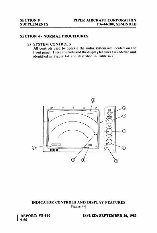
SECTION 9 PIPER AIRCRAFT CORPORATIONSUPPLEMENTS PA-44-180, SEMINOLE
SECTION 4 - NORMAL PROCEDURES
(a) SYSTEM CONTROLSAll controls used to operate the radar system are located on thefront panel. These controls and the display features are indexed andidentified in Figure 4-1 and described in Table 4-3.
INDICATOR CONTROLS AND DISPLAY FEATURESFigure 4-1
l REPORT: VB-860 ISSUED: SEPTEMBER 26, 19809-56
PIPER AIRCRAFT CORPORATION SECTION 9PA-44-180, SEMINOLE SUPPLEMENTS
(1) OFF On/Off function: full CCW rotation ofINTensity control places system in OFFcondition.
(2) INT Rotary control used to regulate brightness(INTensity) of display.
(3) TILT Rotary control used to adjust antennaelevation position. Control indexes incre-ments of tilt from 0 to 12 degrees up ordown.
(4) RANGE Rotary switch used to select one of four12/30/60/90 ranges.
or12/30/60|120
(5) CYC Pushbutton switch used to select cyclicalcontour mode. Data ispresented alternatelyas normal for 0.5 seconds, then contouredfor 0.5 seconds. Pressing switch a secondtime restores normal or WX mode.
(6) Range Field Maximum selected range is displayed.Maximum range is always displayed whenindicator is in on-condition.
(7) Test Field Test block displays three illuminationlevels.
(8) Range Mark Individual label displayed for each rangeIdentifier mark.
(9) Mode Field Operating mode is displayed as WX orCYC.
When system is first turned on, WAIT isdisplayed until system times out (30-40seconds).
INDICATOR CONTROLS AND DISPLAY FEATURESTable 4-3
ISSUED: SEPTEMBER 26, 1980 REPORT: VB-8609-57
SECTION 9 PIPER AIRCRAFT CORPORATIONSUPPLEMENTS PA-44-180, SEMINOLE
(b) PRELIMINARY CONTROL SETTINGSPlace the Indicator controis in the following positions beforeapplying power from the aircraft electrical system:
INTensity control . . . . . . . . . . . . . Fully counterclockwise, in OFFTILT control................................. Fully upwardRANGE switch............................ 12 nautical miles
(c) OPERATIONAL CONTROL SETTINGS(1) Rotate INTensity control clockwise to bring system into ON
condition.(2) Note that WAIT is displayed during warm-up period of
30-40 seconds.(3) When WX is displayed, rotate INTensity control clockwise
until display brightness is at desired level.(4) Set RANGE switch to desired range.(5) Adjust TILT control for desired forward scan area.
(d) PRECAUTIONSIf the radar is to be operated while the aircraft is on the ground:(1) Direct nose of aircraft such that antenna scan sector is free of
large metallic objects (hangars,other aircraft) for a distance of100 yards (90 meters), and tilt antenna fully upward.
WARNING
Do not operate the radar during refuelingoperations or in the vicinity of trucks orcontainers accommodating flammables orexplosives; do not allow personnel within 15feet of area being scanned by antenna whensystem is transmitting.
(2) Flash bulbs can be exploded by radar energy.(3) Since storm patterns aæ never stationary, the display is
constantly changing, and continued observation is alwaysadvisable where areas of turbulence prevail.
IREPORT: VB-860 ISSUED: SEPTEMBER 26, 19809-58
PIPER AIRCRAFT CORPORATION SECTION 9PA-44-180, SEMINOLE SUPPLEMENTS
SECTION 5 - PERFORMANCE
No changes to the basic performance provided by Section 5 of the Pilot'sOperating Handbook are necessary for this supplement.
ISSUED: SEPTEMBER 26, 1980 REPORT: VB-860 |9-59 i
SECTION 9 PIPER AIRCRAFT CORPORATIONSUPPLEMENTS PA-44-180, SEMINOLE
THIS PAGE INTENTIONALLY LEFT BLANK
l REPORT: VB-860 ISSUED: SEPTEMBER 26, 19809-60
PIPER AIRCRAFT CORPORATION SECTION 9PA-44-180, SEMINOLE SUPPLEMENTS
SUPPLEMENT 11
RDR-160 WEATHER RADAR SYSTEM
SECTION 1 - GENERAL
This supplement supplies information necessary for the operation of theairplane when the optional RDR-160 Weather Radar System is installed.The information contained within this supplement is to be used inconjunction with the complete handbook.
This supplement has been "FAA Approved"as a permanent part of thishandbook and must remain in this handbook at all times when the optionalRDR-160 Weather Radar System is installed.
SECTION 2 - LIMITATIONS
No changes to the basic limitations provided by Section 2 of this Pilot'sOperating Handbook are necessary for this supplement.
SECTION 3 - EMERGENCY PROCEDURES
No changes to basic Emergency Procedures by Section 3 of this Pilot'sOperating Handbook aæ necessary for this supplement.
SECTION 4 - NORMAL PROCEDURES
(a) SYSTEM CONTROLSTable 4-3 lists and describes the system controls, all of which aremounted on the panel of the radar indicator. Figure 4-1 illustratesthe location of these controls. Table 4-5 lists the alphanumeric read-outs of range - range marks and mode selection as a function ofswitch position.
ISSUED: SEPTEMBER 26, 1980 REPORT: VB-8609-61
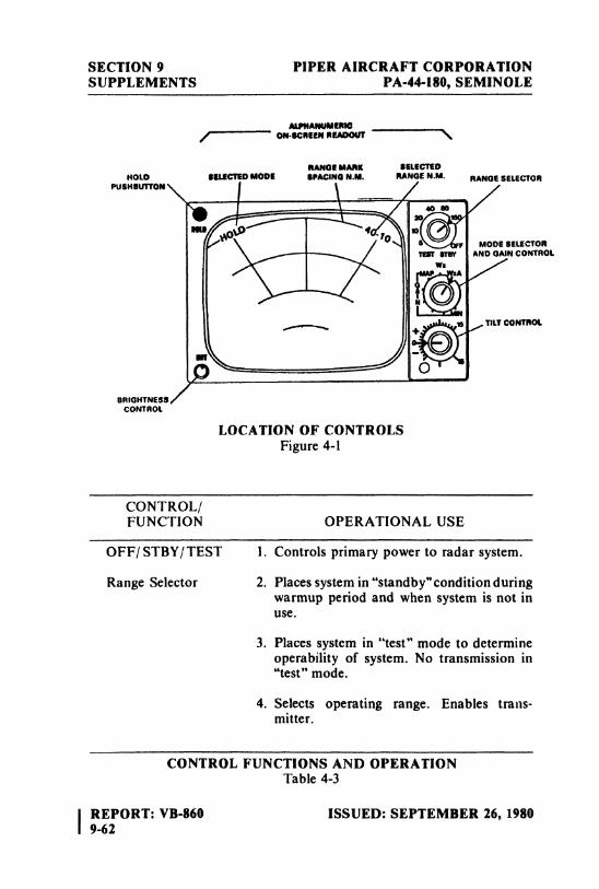
SECTION 9 PIPER AIRCRAFT CORPORATIONSUPPLEMENTS PA-44-180, SEMINOLE
ALPNANUMERIO/ ON-SCHEENREADOUT \
RANGEMARK SELECTEDHOLO SELECTEDMODE SPACING N.M. RANGEN.M MANGESELECTON
PUSHBUTTON
MODE BitECTORTNT star AND GAINCONTROL
WaA
BRIGHTNESSCONTROL
LOCATION OF CONTROLSFigure 4-1
CONTROL/FUNCTION OPERATIONAL USE
OFF/ STBY/ TEST 1. Controls primary power to radar system.
Range Selector 2. Places system in "standby"conditionduringwarmup period and when system is not inuse.
3. Places system in "test" mode to determineoperability of system. No transmission in"test"mode.
4. Selects operating range. Enables trans-mitter.
CONTROL FUNCTIONS AND OPERATIONTable 4-3
IREPORT: VB-860 ISSUED: SEPTEMBER 26, 19809-62
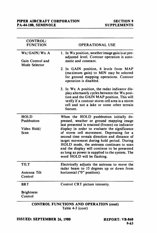
PIPER AIRCRAFT CORPORATION SECTION 9PA-44-180, SEMINOLE SUPPLEMENTS
CONTROL/FUNCTION OPERATIONAL USE
Wx/ GAIN/ Wx A 1. In Wx position, weather image gain isat pre-adjusted level. Contour operation is auto-
Gain Control and matic and constant.Mode Selector
2. In GAIN position, 6 levels from MAP(maximumgain) to MIN may be selectedfor ground mapping operations. Contouroperation is disabled.
3. In Wx A position, the radar indicator dis-play alternately cycles between the Wx posi-tion and the GAIN MAP position. This willverify if a contour storm cell area is a stormcell and not a lake or some other terrainfeature.
HOLD When the HOLD pushbutton initially de-Pushbutton pressed, weather or ground mapping image
last presented is retained (frozen)on indicatorVideo Hold/ display in order to evaluate the significanceScan of storm cell movement. Depressing for a
second time reveals direction and distance oftarget movement during hold period. DuringHOLD mode, the antenna continues to scanand the display will continue to be presentedas long as power is supplied to the system. Theword HOLD will be flashing.
TILT Electrically adjusts the antenna to move theradar beam to 15 degrees up or down from
Antenna Tilt horizontal ("0" position).Control
BRT Control CRT picture intensity.
BrightnessControl
CONTROL FUNCTIONS AND OPERATION (cont)Table 4-3 (cont)
ISSUED: SEPTEMBER 26, 1980 REPORT: VB-8609-63
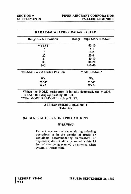
SECTION 9 PIPER AIRCRAFT CORPORATIONSUPPLEMENTS PA-44-180, SEMINOLE
RADAR-160 WEATHER RADAR SYSTEM
Range Switch Position Range-Range Mark Readout
**TEST 40-105 5-1
10 10-220 20440 40-1080 80-20
160 16040
Wx-MAP-Wx A Switch Position Mode Readout*
Wx WxMAP MAPWxA WxA
*When the HOLD pushbutton is initially depressed, the MODEREADOUT displays flashing HOLD.
**The MODE READOUT displays TEST.
ALPHANUMERIC READOUTTable 4-5
(b) GENERAL OPERATING PRECAUTIONS
WARNING
Do not operate the radar during refuelingoperations or in the vicinity of trucks orcontainers accommodating flammables orexplosives; do not allow personnel within 15feet of area being scanned by antenna whensystem is transmitting.
IREPORT: VB-860 ISSUED: SEPTEMBER 26, 19809-64
PIPER AIRCRAFT CORPORATION SECTION 9PA-44-180, SEMINOLE SUPPLEMENTS
(1) Flash bulbs can be exploded by radar energy.(2) Since storm patterns are never stationary, the display is con-
stantly changing, and continued observation is always ad-visable where areas of turbulence prevail.
NOTE
See RDR-160 pilot manual for detailedoperating information and analysis of targets.
SECTION 5 - PERFORMANCE
No changes to the basic performance provided by Section 5 of the Pilot'sOperating Handbook are necessary for this supplement.
ISSUED: SEPTEMBER 26, 1980 REPORT: VB-860 |9-65 I
SECTION 9 PIPER AIRCRAFT CORPORATIONSUPPLEMENTS PA-44-180, SEMINOLE
THIS PAGE INTENTIONALLY LEFT BLANK
I REPORT: VB-860 ISSUED: SEPTEMBER 26, 19809-66
PIPER AIRCRAFT CORPORATION SECTION 9PA-44-180, SEMINOLE SUPPLEMENTS
SUPPLEMENT 12
RDR-160/IN-2026A WEATHER RADAR SYSTEM
SECTION 1 - GENERAL
This supplement supplies information necessary for the operation of theairplane when the optional RDR-160/IN-2026A Weather Radar System isinstaned. The information contained within this supplement is to be used inconjunction with the complete handbook.
This supplement has been "FAA Approved"as a permanent part of thishandbook and must remain in this handbook at all times when the optionalRDR-160/IN-2026A Weather Radar System is installed.
SECTION 2 - LIMITATIONS
No changes to the basic limitations provided by Section 2 of this Pilot'sOperating Handbook are necessary for this supplement.
SECTION 3 - EMERGENCY PROCEDURES
No changes to the basic Emergency Procedures by Section 3 of thisPilot's Operating Handbook are necessary for this supplement.
ISSUED: SEPTEMBER 26, 1980 REPORT: VB-8609-67
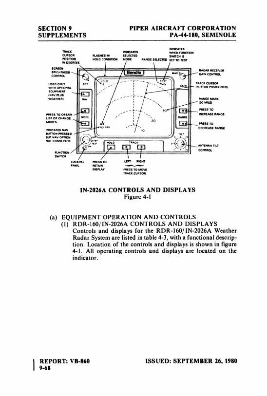
SECTION 9 PIPER AIRCRAFT CORPORATIONSUPPLEMENTS PA-44-180, SEMINOLE
INDICATESTRACK INDICATES WHEN FUNCTIONCURSOR FIASHES W SELECTED SWirCN SPOSfDON HOLOCONDITION MODE RANGESELECTEDSET TO TEST
DSEGREES
USEDONLY BRToto ---r TEST
TRACKCURSORWITH OFilONAL BUTTONPOSITIONED)ENOUWMENT
W£ATNER) -'
RANGEMARK
(30 MILÆl
30 PRESS TOPRESS TO OOTAIN INCREASERANGEUST OR CHANGE MoDE / RANGE
MODESL
20PRESS TO
INDICATESNAVNO NAv DECREASERANGE
BUTTON PRESSEO LTBUT NAVOPflONNOT CO NO RACK
ANTENNA TitT
LOCKING PRESS TO LEFT RIGHTPAWL RETAIN M
DISPLAY PRESS TO MOVETAACK CURSOR
IN-2026A CONTROLS AND DISPLAYSFigure 4-1
(a) EQUIPMENT OPERATION AND CONTROLS(I) RDR-160|IN-2026A CONTROLS AND DISPLAYS
Controls and displays for the RDR-160/ IN-2026A WeatherRadar System are listed in table 4-3, with a functional descrip-tion. Location of the controls and displays is shown in figure4-1. All operating controls and displays are located on theindicator.
REPORT: VB-860 ISSUED: SEPTEMBER 26, 19809-68
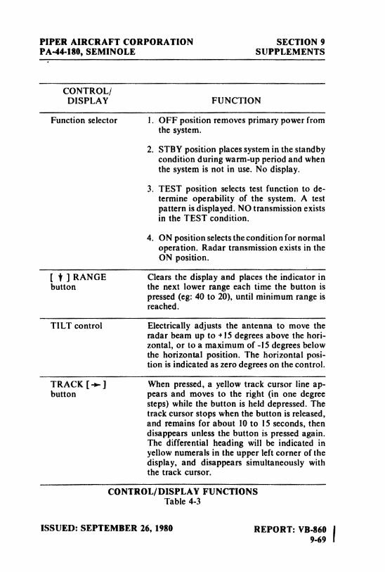
PIPER AIRCRAFT CORPORATION SECTION 9PA-44-180, SEMINOLE SUPPLEMENTS
CONTROL/DISPLAY FUNCTION
Function selector 1. OFF position removes primary power fromthe system.
2. STBY position places system in the standbycondition during warm-up period and whenthe system is not in use. No display.
3. TEST position selects test function to de-termine operability of the system. A testpattern is displayed. NO transmission existsin the TEST condition.
4. ON position selects the condition for normaloperation. Radar transmission exists in theON position.
[ † ] RANGE Clears the display and places the indicator inbutton the next lower range each time the button is
pressed (eg:40 to 20), until minimum range isreached.
TILT control Electrically adjusts the antenna to move theradar beam up to +15 degrees above the hori-zontal, or to a maximum of
-15
degrees belowthe horizontal position. The horizontal posi-tion is indicated as zero degrees on the control.
TRACK [+] When pressed, a yellow track cursor line ap-button pears and moves to the right (in one degree
steps) while the button is held depressed. Thetrack cursor stops when the button is released,and remains for about 10 to 15 seconds, thendisappears unless the button is pressed again.The differential heading will be indicated inyellow numerals in the upper left corner of thedisplay, and disappears simultaneously withthe track cursor.
CONTROL/DISPLAY FUNCTIONSTable 4-3
ISSUED: SEPTEMBER 26, 1980 REPORT: VB-860 |9-69 I
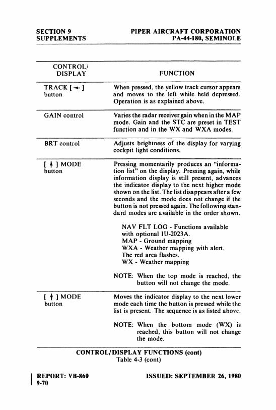
SECTION 9 PIPER AIRCRAFT CORPORATIONSUPPLEMENTS PA-44-180, SEMINOLE
CONTROL/DISPLAY FUNCTION
TRACK [-+-] When pressed, the yellow track cursor appearsbutton and moves to the left while held depressed.
Operation is as explained above.
GAIN control Varies the radar receiver gain when inthe MAPmode. Gain and the STC are preset in TESTfunction and in the WX and WXA modes.
BRT control Adjusts brightness of the display for varyingcockpit light conditions.
[ # ] MODE Pressing momentarily produces an "informa-button tion list" on the display. Pressing again, while
information display is still present, advancesthe indicator display to the next higher modeshown on the list. The list disappears after a fewseconds and the mode does not change if thebutton is not pressed again. The following stan-dard modes are available in the order shown.
NAV FLT LOG - Functions availablewith optional IU-2023A.MAP - Ground mappingWXA - Weather mapping withalert.The red area flashes.WX - Weather mapping
NOTE: When the top mode is reached, thebutton will not change the mode.
[ † ] MODE Moves the indicator display to the next lowerbutton mode each time the button is pressed while the
list is present. The sequence is as listed above.
NOTE: When the bottom mode (WX) isreached, this button will not changethe mode.
CONTROL/DISPLAY FUNCTIONS (cont)Table 4-3 (cont)
IREPORT: VB-860 ISSUED: SEPTEMBER 26, 19809-70
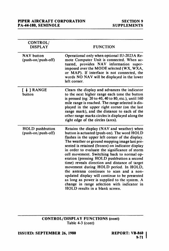
PIPER AIRCRAFT CORPORATION SECTION 9PA-44-180, SEMINOLE SUPPLEMENTS
CONTROL/DISPLAY FUNCTION
NAV button Operational only when optional IU-2023A Re-(push-on/push-off) mote Computer Unit is connected. When ac-
tuated, provides NAV information super-imposed over the MODE selected (WX, WXA,or MAP). If interface is not connected, thewords NO NAV will be displayed in the lowerleft corner.
[ # ] RANGE Clears the display and advances the indicatorbutton to the next higher range each time the button
is pressed (eg:20 to 40, 40 to 80, etc.), until 160mile range is reached. The range selected is dis-played in the upper right corner (on the lastrange mark), and the distance to each of theother range marks circles is displayed along theright edge of the circles (arcs).
HOLD pushbutton Retains the display (NAV and weather) when(push-on/push-off) button is actuated (push-on).The word HOLD
flashes in the upper left corner of the display.The weather or ground mapping image last pre-sented is retained (frozen)on indicator displayin order to evaluate the significance of stormcell movement. Switching back to normal op-eration (pressingHOLD pushbutton a secondtime) reveals direction and distance of targetmovement during HOLD period. In HOLD,the antenna continues to scan and a non-updated display will continue to be presentedas long as power is supplied to the system. Achange in range selection with indicator inHOLD results in a blank screen.
CONTROL/DISPLAY FUNCTIONS (cont)Table 4-3 (cont)
ISSUED: SEPTEMBER 26, 1980 REPORT: VB-860 |9-71 i
SECTION 9 PIPER AIRCRAFT CORPORATIONSUPPLEMENTS PA-44-180, SEMINOLE
(b) OPERATING PRECAUTIONS
WARNING
Do not operate the radar during refuelingoperations or in the vicinity of trucks orcontainers accommodating flammables orexplosives. Do not allow personnel within 15feet of area being scanned by antenna whensystem is transmitting.
(1) Flash bulbs can be exploded by radar energy.(2) Since storm patterns are never stationary, the display is con-
stantly changing. Continued observation is always advisablein stormy areas.
SECTION 5 - PERFORMANCE
No changes to the basic performance provided by Section 5 of the Pilot'sOperating Handbook are necessary for this supplement.
I REPORT: VB-860 ISSUED: SEPTEMBER 26, 19809-72
PIPER AIRCRAFT CORPORATION SECTION 9PA-44-180, SEMINOLE SUPPLEMENTS
SUPPLEMENT 13
RCA COLOR WEATHERSCOUT II WEATHER RADAR SYSTEM
SECTION 1 - GENERAL
This supplement supplies information necessary for the operation of theairplane when the optional RCA Color WeatherScout II Weather RadarSystem is installed. The information contained within this supplement is tobe used in conjunction with the complete handbook.
This supplement has been "FAA Approved" as a permanent part of thishandbook and must remain in this handbook at all times when the optionalRCA Color WeatherScout II Weather Radar System is installed.
SECTION 2 - LIMITATIONS
No changes to the basic limitations provided by Section 2 of this Pilot'sOperating Handbook are necessary for this supplement.
SECTION 3 - EMERGENCY PROCEDURES
No changes to the basic Emergency Procedures by Section 3 of thisPilot's Operating Handbook are necessary for this supplement.
ISSUED: SEPTEMBER 26, 1980 REPORT: VB-860 |9-73 I
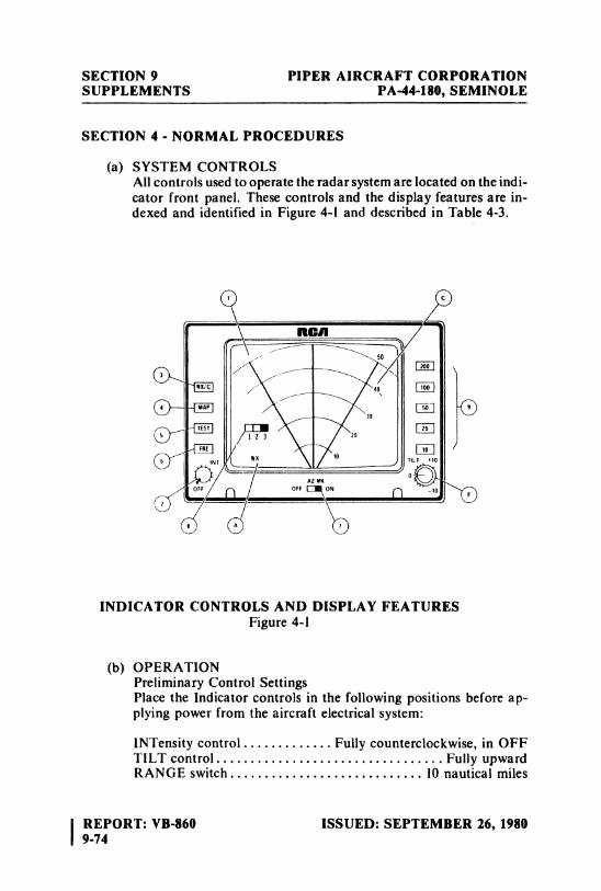
SECTION 9 PIPER AIRCRAFT CORPORATIONSUPPLEMENTS PA-44-180, SEMINOLE
SECTION 4 - NORMAL PROCEDURES
(a) SYSTEM CONTROLSAll controts used to operate the radar system are located on the indi-cator front panel. These controls and the display features are in-dexed and identified in Figure 4-i and described in Table 4-3.
INDICATOR CONTROLS AND DISPLAY FEATURESFigure 4-1
(b) OPERATIONPreliminary Control SettingsPlace the Indicator controls in the following positions before ap-plying power from the aircraft electrical system:
INTensity control . . . . . . . . . . . . . Fully counterclockwise, in OFFTILTcontrol.................................FullyupwardRANGE switch............................ 10 nautical miles
IREPORT: VB-860 ISSUED: SEPTEMBER 26, 19809-74
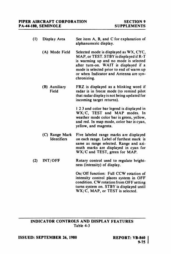
PIPER AIRCRAFT CORPORATION SECTION 9PA-44-180, SEMINOLE SUPPLEMENTS
(1) Display Area See item A, B, and C for explanation ofalphanumeric display.
(A) Mode Field Selected mode is displayed as WX, CYC,MAP, or TEST. STBYisdisplayed if R-Tis warming up and no mode is selectedafter turn-on. WAIT is displayed if amode is selected prior to end of warm upor when Indicator and Antenna are syn-chronizing.
(B) Auxiliary FRZ is displayed as a blinking word ifField radar is in freeze mode (to remind pilot
that radar display is not being updated forincoming target returns).
I 2 3 and color bar legend is displayed inWX/C, TEST and MAP modes. Inweather mode color bar is green, yellow,and red. In map mode, color bar is cyan,yellow, and magenta.
(C) Range Mark Five labeled range marks are displayedIdentifiers on each range. Label of furthest mark is
same as range selected. Range and azi-muth marks are displayed in cyan forWX/C and TEST, green for MAP.
(2) INT/OFF Rotary control used to regulate bright-ness (intensity)of display.
On/Off function: Full CCW rotation ofintensity control places system in OFFcondition. CW rotation from OFF settingturns system on. STBY is displayed untilWX/C, MAP, or TEST is selected.
INDICATOR CONTROLS AND DISPLAY FEATURESTable 4-3
ISSUED: SEPTEMBER 26, 1980 REPORT: VB-860 |9-75 i
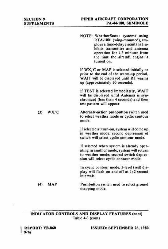
SECTION 9 PIPER AIRCRAFT CORPORATIONSUPPLEMENTS PA-44-180, SEMINOLE
NOTE: WeatherScout systems usingRTA-1001 (wing-mounted),em-ploys a time-dela y circuit that in-hibits transmitter and antennaoperation for 4.5 minutes fromthe time the aircraft engine isturned on.
If WX/C or MAP is selected initially orprior to the end of the warm-up period,WAIT will be displayed until RT warmsup (approximately30 seconds).
If TEST is selected immediately, WAITwill be displayed until Antenna is syn-chronized (lessthan 4 seconds) and thentest pattern will appear.
(3) WX|C Alternate-action pushbutton switch usedto select weather mode or cyclic contourmode.
If selected at turn-on, system willcome upin weather mode; second depression ofswitch will select cyclic contour mode.
If selected when system is already oper-ating in another mode, system will returnto weather mode; second switch depres-sion will select cyclic contour mode.
In cyclic contour mode, 3-level (red)dis-play will flash on and off at I/2-secondintervals.
(4) MAP Pushbutton switch used to select groundmapping mode.
INDICATOR CONTROLS AND DISPLAY FEATURES (cont)Table 4-3 (cont)
IREPORT: VB-860 ISSUED: SEPTEMBER 16, 19809-76
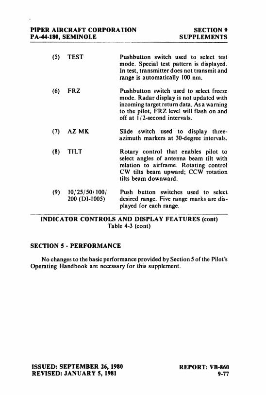
PIPER AIRCRAFT CORPORATION SECTION 9PA-44-180, SEMINOLE SUPPLEMENTS
(5) TEST Pushbutton switch used to select testmode. Special test pattern is displayed.In test, transmitter does not transmit andrange is automatically 100 nm.
(6) FRZ Pushbutton switch used to select freezemode. Radar display is not updated withincoming target return data. As a warningto the pilot, FRZ level will flash on andoff at I/2-second intervals.
(7) AZ MK Slide switch used to display thæe-azimuth markers at 30-degree intervals.
(8) TILT Rotary control that enables pilot toselect angles of antenna beam tilt withrelation to airframe. Rotating controlCW tilts beam upward; CCW rotationtilts beam downward.
(9) 10/25/50|100/ Push button switches used to select200 (DI-1005) desired range. Five range marks are dis-
played for each range.
INDICATOR CONTROLS AND DISPLAY FEATURES (cont)Table 4-3 (cont)
SECTION 5 - PERFORMANCE
No changes to the basic performance provided by Section 5 of the Pilot'sOperating Handbook are necessary for this supplement.
ISSUED: SEPTEMBER 26, 1980 REPORT: VB-860REVISED: JANUARY 5, 1981 9.77
SECTION 9 PIPER AIRCRAFT CORPORATIONSUPPLEMENTS PA-44-180, SEMINOLE
THIS PAGE INTENTIONALLY LEFT BLANK
\ REPORT: VB-860 ISSUED: SEPTEMBER 26, 1980i 9-78
PIPER AIRCRAFT CORPORATION SECTION 9PA-44-180, SEMINOLE SUPPLEMENTS
PILOT'S OPERATING HANDBOOKAND
FAA APPROVED AIRPLANE FLIGHT MANUAL
SUPPLEMENT NO. 14FOR
ELECTRICAL D1STRIBUTION BUS MODIFICATION
This supplement must be attached to the Pilot's Operating Handbookand FAA Approved Airplane Flight Manual when the ElectricalDistribution Bus Modification is installed in accordance with Piper Kit No.764 937V.
The information contained herein supplements or supersedes theinformation in the basic Pilot's Operating Handbook and FAA ApprovedAirplane Flight Manual only in those areas listed herein. For limitations,procedures and performance information not contained in this supplement,consult basic Pilot's Operating Handbook and FAA Approved AirplaneFlight Manual.
FAA APPROVEDWARD EVANSD.O.A. NO. SO-IPIPER AIRCRAFT CORPORATIONVERO BEACH, FLORIDA
DATE OF APPROVAI
ISSUED: MARCH 14, 1983 REPORT: VB-860 |9-79 i
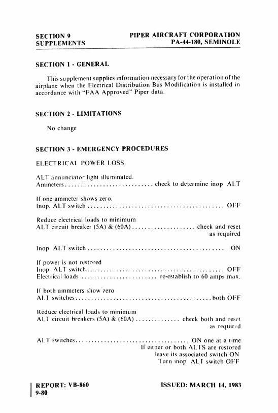
SECTION 9 PIPER AIRCRAFT CORPORATIONSUPPLEMENTS PA-44-180, SEMINOLE
SECTION I - GENERAL
This supplement supplies information necessary for theoperation oftheairplane when the Electrical Distribution Bus Modification is installed inaccordance with "FAA Approved" Piper data.
SECTION 2 - LIMITATIONS
No change
SECTION 3 - EMERGENCY PROCEDURES
ELECTRICAL POWER LOSS
ALT annunciator Ught iluminated.Ammeters............................ check to determine inop ALT
If one ammeter shows zero.Inop. ALT switch .............. ... . ................ OFF
Reduce electrical loads to minimumALT circuit breaker (5A) & (60A).................... check and reset
as required
lnop ALTswitch............... . ... . . ...............ON
If power is not restoredinop ALT switch ............. .. ...................... OFFElectrical loads ........................ re-establish to 60 amps max.
If both ammeters shOW 7000
ALT switches................ . . . .
...............both
OFF
Reduce electrical loads to minimumALT circuit breakers (5A) & (60A) .............. check both and reset
as required
ALT switches............... . ............... ON one at a timeIf either or both ALTS are restored
leave its associated switch ONTurn inop ALI switch OFF
REPORT: VB-860 ISSUED: MARCH 14, 19839-80
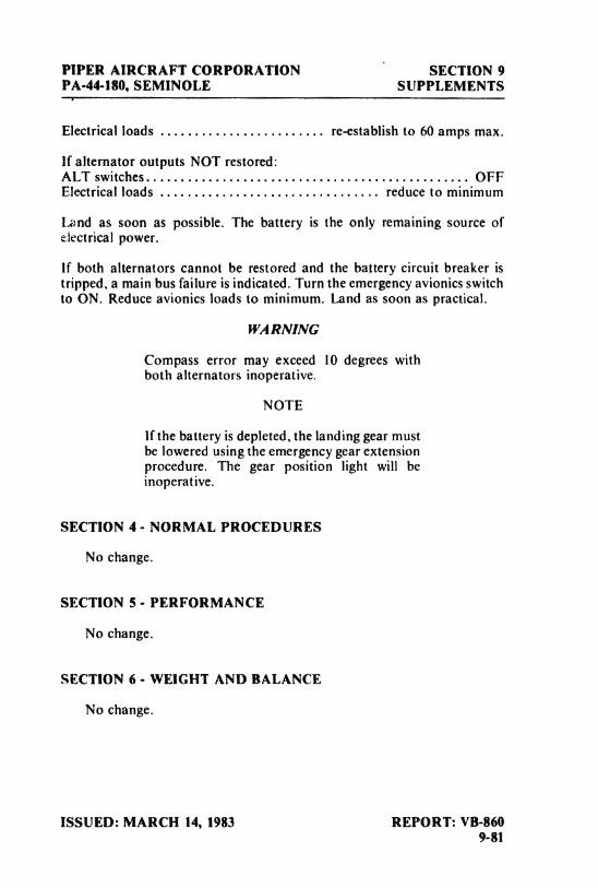
PIPER AIRCRAFT CORPORATION SECTION 9PA-44-180, SEMINOLE SUPPLEMENTS
Electrical loads . . . . . . . . . . . . . . . . . . . . . . . . re-establish to 60 amps max.
If alternator outputs NOT restored:ALT switches............................................... OFFElectrical loads ................................ reduce to minimum
Land as soon as possible. The battery is the only remaining source ofelectrical power.
If both alternators cannot be restored and the battery circuit breaker istripped, a main bus failure is indicated. Turn the emergency avionics switchto ON. Reduce avionics loads to minimum. Land as soon as practical.
WARNING
Compass error may exceed 10 degrees withboth alternators inoperative.
NOTE
If the battery is depleted, the landing gear mustbe lowered using the emergency gear extensionprocedure. The gear position light will beinoperative.
SECTION 4 - NORMAL PROCEDURES
No change.
SECTION 5 - PERFORMANCE
No change.
SECTION 6 - WEIGHT AND BALANCE
No change.
ISSUED: MARCH 14, 1983 REPORT: VB-8609-81
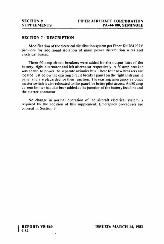
SECTION 9 PIPER AIRCRAFT CORPORATIONSUPPLEMENTS PA-44-180, SEMINOLE
SECTION 7 - DESCRIPTION
Modification of the electrical distribution system per Piper Kit 764 937Vprovides for additional isolation of main power distribution wires andelectrical busses.
Three 60 amp circuit breakers were added for the output lities of thebattery, right alternator and left alternator respectively. A 30 amp breakerwas added to power the separate avionics bus. These four new breakers arelocated just below the existing circuit breaker panel on the right instrumentpanel and are placarded for their function. The existing emergency avionicsmaster switch is also relocated to this panel for better pilot access. An 80 ampcurrent limiter has also been added at the junctionof the battery feed line andthe starter contactor.
No change in normal operation of the aircraft electrical system isrequired by the addition of this supplement. Emergency procedures arecovered in Section 3.
IREPORT: VB-860 ISSUED: MARCH 14, 19839-82
TABLE OF CONTENTS
SECTION 10
SAFETY TIPS
Paragraph PageNo. No.
10.1 General .......................................... 10-110.3 Safety Tips ....................................... 10-1
REPORT: VB-86010-i

PIPER AIRCRAFT CORPORATION SECTION 10PA-44-180, SEMINOLE SAFETY TIPS
SECTION 10
SAFETY TIPS
10.1 GENERAL
This section provides safety tips of particular value in the operation ofthe Piper Seminole.
10.3 SAFETY TIPS
(a) Learn to trim for takeoff so that only a very light back pressure onthe wheel is required to lift the airplane off the ground.
(b) On takeoff, do not retract the gear prematurely. The airplane maysettle and make contact with the ground because of lack of flyingspeed, atmospheric conditions, or rolling terrain.
(c) Flaps may be lowered at airspeeds up to 111 KIAS. To reduce flapoperating loads, it is desirable io have the airplane at a slower speedbefore extending the flaps. The flap step will not support weight ifthe flaps are in any extended position. The flaps must be placed inthe "UP" position before they will lock and support weight on thestep.
(d) Before attempting to reset any circuit breaker, allow a two to fiveminute cooling off period.
(e) Always determine position of landing gear by checking the gearposition lights.
(f) The shape of the nacelle fuel tanks is such thatin certain maneuversand with low fuel levels, the fuel may move away from the tankoutlet. If the outlet is uncovered, the fuel flow will be interruptedand a temporary loss of power may result. Pilots can prevent in-advertent uncovering of the outlet by avoiding maneuvers whichcould result in uncovering the outlet.
ISSUED: MARCH 23, 1978 REPORT: VB-86010-1
SECTION 10 PIPER AIRCRAFT CORPORATIONSAFETY TIPS PA-44-180, SEMINOLE
Extreme running turning takeoffs should be avoided.
Prolonged slips and skids which result in excess of 2000 feet ofaltitude loss, or other radical or extreme maneuvers which couldcause uncovering of the fuel outlet must be avoided as fuel flowinterruption may occur when the tank being used is not full.
(g) The rudder pedals are suspended from a torque tube which extendsacross the fuselage. The pilot should become familiar with theproper positioning of his feet on the rudder pedals so as to avoidinterference with the torque tube when moving the rudder pedalsor operating the toe brakes.
|(h) Anti-collision lights should not be operating when flying through
clouds, fog, or haze, since reflected light can produce spacial disori-entation. Strobe lights should not be used in close proximity to theground such as during taxiing, takeoff or landing.
(i) In an effort to avoid accidents, pilots should obtain and study thesafety related information made available in FAA publications suchas regulations, advisory circulars, Aviation News, AIM and safetyaids.
(j) Pilots who fly above 10,000 feet should be aware of the need forspecial physiological training. Appropriate training is available atapproximately twenty-three Air Force Basesthroughout the UnitedStates for a small fee. The training is free at the NASA Center inHouston and at the FAA Aeronautical Center in Oklahoma.
Forms to be completed (Physiological Training Application andAgreement) for application for the training course may be obtainedby writing to the following address:
Chief of Physiological Training, AAC-143FAA Aeronautical CenterP. O. Box 25082Oklahoma City, Oklahoma 73125
It is recommended that all pilots who plan to fly above 10,000 feettake this training before flying this high and then take refreshertraining every two or three years.
REPORT: VB-860 ISSUED: MARCH 23, 197810-2 REVISED: SEPTEMBER 14, 1979
PIPER AIRCRAFT CORPORATION SECTION 10PA-44-180, SEMINOLE SAFETY TIPS
(k) Sluggish RPM control and propeller overspeed with poor RPMrecovery after rapid throttle application are indications thatnitrogen pressure in the propeller dome is low.
(1) Experience has shown that the training advantage gained by pullinga mixture control or turning off the fuel to simulate engine failure atlow altitude is not worth the risk assumed, therefore it is recom-mended that instead of using either of these procedures to simulateloss of power at low altitude, the throttle be retarded slowly to idleposition. Fast reduction of power may be harmful to the engine. Apower setting of 2000 RPM and 11.5 in. Hg MAP is recommendedfor simulated one engine operation.
(m)Before starting either engine, check that all radio switches, lightswitches and the pitot heat switch are in the OFF position so as notto create an overloaded condition when the starter is engaged.
(n) The airplane should not be flown in severe turbulence as damage tothe airframe structure could result.
(o) The best speed for takeoff is about 75 KIAS under normalconditions. Trying to pull the airplane off the ground at too low anairspeed decreases the controllability of the airplane in the event ofan engine failure.
ISSUED: MARCH 23, 1978 REPORT: VB-86010-3

Related Documents