SDH BASICS Niranjan B Regional Telecom Training Center Mysore

sdhbasics-140426061715-phpapp02
Dec 05, 2015
SDH specification
Welcome message from author
This document is posted to help you gain knowledge. Please leave a comment to let me know what you think about it! Share it to your friends and learn new things together.
Transcript

SDH BASICS
Niranjan BRegional Telecom Training Center Mysore


DISADVANTAGES OF PDH
• NO UNIVERSAL STANDARD• DIFFERENT HIERARCHIES AROUND THE WORLD• PDH NETWORK MANAGEMENT IS PROPRIETARY• DROPPING OF INDIVIDUAL CHANNELS IN HIGHER
ORDER STREAM• NON-HOMOGENEITY OF EQUIPMENT• CHANNEL SEGREGATION PROBLEM• PROBLEM OF CROSS CONNECTION
S.D.H. Evolution
• Fibre Optic Bandwidth :• Technical Sophistication. • Intelligence :. • Customer Service Needs


SECTION OVER HEAD(SOH)
• SOH bytes provide communication channels to cater for: • OA&M facilities.• user channels.• protection switching.• section performance• frame alignment• other functions.


For 1.544 Mbit PDH signal (North America and Japan Standard), there are 25 bytes in 125 micro second and for 2.0408 Mbit per second signal, there are 32 bytes in 125 micro second. Taking some additional bytes for supervisory purposes, 27 bytes can be allotted for holding 1.544 Mbit per second signal, i.e. 9 rows x 3 columns. Similarly, for 2.048 Mbit per second signal, 36 bytes are allotted in 125 micro seconds, i.e. 9 rows x 4 columns. Therefore, it could be said 9 rows are matched to both hierarchies.

SDH STANDARDS
STM-1 155.52 Mbps
SMT-4 622.08 Mbps
STM-16 2588.32 Mbps 2.5G
STM-64 9953.28 Mbps 10G
STM-0 = 1/3rd of STM-1
51.840 Mbps Used in SONET

Synchronous Transport Module-STM
• This is the information structure used to support information pay load and over head information field organised in a block frame structure which repeats every 125 micro seconds

BASIC DEFINATIONS
• Container: First Entry point of PDH signal, in which signal is prepared ( adding fixed stuff, JC, Justification Opportunity byte) so that it can enter in to VC stage .32 to 34 byet fo 2Mb

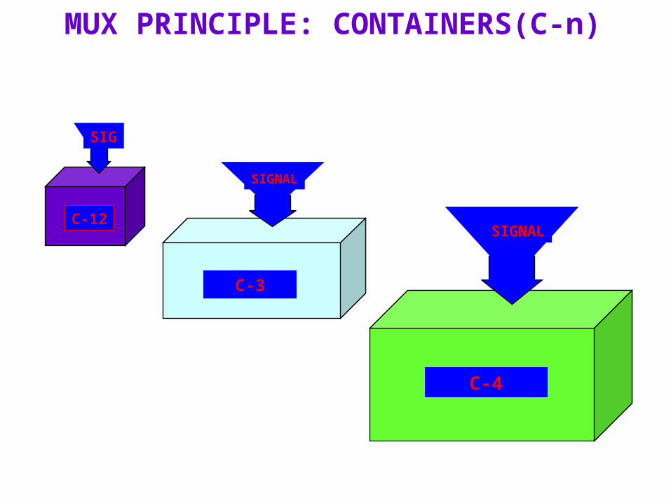
MUTIPLEXING PRINCIPLE
CONTAINER
SIGNAL
Container-n( n=1-4 ): A container is the information structure which forms the network synchronous information payload for a virtual container
2Mb
C-4
SIGNAL
C-3
SIGNAL
C-12
SIG
MUX PRINCIPLE: CONTAINERS(C-n)

BASIC DEFINATIONS
• Virtual Container(VC):
• VC= Container(C) +POH (path over head)
• 35 byte for 2Mb

MUX PRINCIPLE: VC-nVirtual Container-n(VC-n):It is the information structure used to support path layer connections in the SDH. Two types of VCs: Lower order VC-n(n=1,2)
Higher order Vc-n(n=3,4)
CONTAINER
POH

Tributary Unit
• A tributary unit is a information structure which provides adaptation between the lower order path layer and the higher order path layer. It consists of a information pay load (lower order virtual container) and a tributary unit pointer which indicates the offset of the pay load frame start relating to the higher order VC frame start.
• Tributary unit 1 for VC-1 and Tributary unit 2 is for VC-2 and Tributary unit 3 is for VC-3, when it is mapped for VC-4 through tributary group-3. TU-3 pointer consists of 3 bytes out of 9 bytes. Three bytes are H1, H2, H3 and remaining bytes are fixed bytes. TU-1 pointers are one byte interleaved in the TUG-2.

CONTAINERPOH
PTR
MUX PRINCIPLE: TU-n/ AU•It is an information structure which provides adaptation between two layers: -Between lower and higher order path layers for TU -Between higher order path layer and section layer for AU
POINTER is an indicator whose value defines the frame offset of a VC with respect to the frame reference of the transport entity on which it is supported
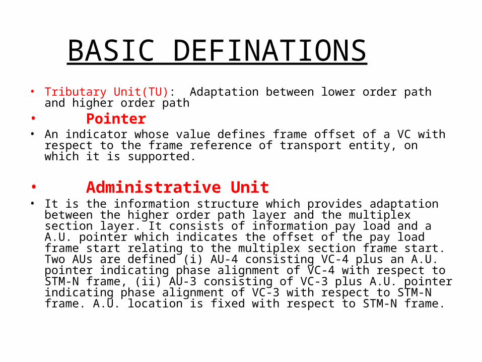
BASIC DEFINATIONS• Tributary Unit(TU): Adaptation between lower order path and higher
order path • Pointer• An indicator whose value defines frame offset of a VC with respect to the
frame reference of transport entity, on which it is supported.
• Administrative Unit • It is the information structure which provides adaptation between the
higher order path layer and the multiplex section layer. It consists of information pay load and a A.U. pointer which indicates the offset of the pay load frame start relating to the multiplex section frame start. Two AUs are defined (i) AU-4 consisting VC-4 plus an A.U. pointer indicating phase alignment of VC-4 with respect to STM-N frame, (ii) AU-3 consisting of VC-3 plus A.U. pointer indicating phase alignment of VC-3 with respect to STM-N frame. A.U. location is fixed with respect to STM-N frame.

Tributary Unit Group
• One or more tributaries are contained in tributary unit group. A TUG-2 consist of homogenous assembly of identical TU-1s or TU-2.
• TUG-3 consists of a homogenous assembly of TUG-2s or TU-3.
• TUG-2 consists of 3 TU-12s (For 2.048 Mbit/sec). TUG-3 consists of either 7 TUG-2 or one TU-3.

BASIC DEFINATIONS• Administrative Group• AUG consists of a homogenous assembly of AU-3s or an AU-4.
• Concatenation• The procedure with which the multiple virtual container are associated
with one another, with the result their combined capacity could be used as a single container across which bit sequence
• Network Node Interface (NNI)• The interface at a network node which is used to interconnect with
another network node. • integrity is maintained. •

1544kbps
2048kbps
6312kbps
34368kbps
44736kbps
139264kbps
C-11
C-12
C-2
C-3
C-4
VC-11
VC-12
VC-2
TUG-2
X1
X3
X4
VC-3
VC-3TUG-3
VC-4
TU-11
TU-12
TU-2
TU-3
AU-3
AU-4AUG
STM-N
X7
X7
X1
X3
X3
XN
1544kbps
2048kbps
6312kbps
34368kbps
44736kbps
139264kbps
C-11
C-12
C-2
C-3
C-4
VC-11
VC-12
VC-2
TUG-2
X1
X3
X4
VC-3
VC-3TUG-3
VC-4
TU-11
TU-12
TU-2
TU-3
AU-3
AU-4AUG
STM-N
X7
X7
X1
X3
X3
XN
C-11
C-12
C-2
C-3
C-4
VC-11
VC-12
VC-2
TUG-2
X1
X3
X4
VC-3
VC-3TUG-3
VC-4
TU-11
TU-12
TU-2
TU-3
AU-3
AU-4
TU-11
TU-12
TU-2
TU-3
AU-3
AU-4AUG
STM-N
X7
X7
X1
X3
X3
XN
Generic Multiplexing Structure
9 X 3
9 X 4

Embedded Overhead Bytes
VC-11/12/ 2 POH
STM-1 SOH
J1B3C2G1F2H4F3K3N1
V5J2N2K4
AU - PTR
VC-3/4 POHA1 A1 A1 A2 A2 A2 J0 X X
D1 D2 D3
B2 B2 B2 K1 K2D4 D5 D6 D7 D8 D9
D10 D11 D12 S1 M 1 E2 X X
B1 E1 F1 X X
H1 Y Y H2 1 1 H3 H3 H3
Media dependent bytesX Reserved for national use
SOH: Section overheadPOH: Path overhead
The overheads (SOH, POH) are used for maintenance and supervision of the SDH transmission network.
RSOH
MSOH Payload
P O
H
Pointer

Functions of Regenerator Section Overhead
Parity check(B1 calculated by regenerator and multiplexers)
Data communication channels(D1...D3, F1 between regenerators)
Voice communication channels(E1 between regenerators)
Frame Alignment(A1, A2)
Section Trace(J0 Identficationof regenerator source)
A1 A1 A1 A2 A2 A2 J0
B1 E1 F1
D1 D2 D3
B2 B2 B2 K1 K2
D4 D5 D6
D7 D8 D9
D10 D11 D12
S1 M1 E2
AU - Pointer

Functions of Multiplexer Section Overhead
Parity check (B2)
Alarm information (K2)
Remote error indication (M1,K2)
Automatic protection switching (K1, K2 Bytes)
Data communication channels (D4 to D12 between multiplexers)
Clock source information (S1)
Voice communications channels (E2 between multiplexers)
A1 A1 A1 A2 A2 A2 J0
B1 E1 F1
D1 D2 D3
B2 B2 B2 K1 K2
D4 D5 D6
D7 D8 D9
D10 D11 D12
S1 M1 E2
AU - Pointer

Functions of Path Overhead
V5J2N2K4
J1B3C2G1F2H4F3K4N1
VC-3/4 POH
VC-11/12/2 POH
Parity check B3, V5/ BIP-2 calculated by path terminating point
Alarm and performance information (V5, G1)
Structure of the VC Signal label C2
Multiframe indication for TUs (H4)
User communications channelbetween path elements (F2, F3)
Identification of the Path Source (Path Trace J1, J2)

SOH BYTES• A-1, A-2 are framing bytes. Their values are : • A1 : 11110110• A2 : 00101000• These two types of bytes form 16 bit Frame Alignment Word (FAW).• FAW formed by the last A-1 byte and the adjacent A-2 byte, in the
transmitter sequence defines the frame reference for each of signal rates.
• There are 3 A-1 bytes in STM-1 and 3 A-2 bytes in STM-1. In higher order STM their number increases with STM order. In STM-4, there
will be 12 A-1 bytes and 12 A-2 bytes.

SOH BYTES -A1, A2
• A-1, A-2 are framing bytes. Their values are : • A1 : 11110110• A2 : 00101000• These two types of bytes form 16 bit Frame Alignment Word
(FAW). FAW formed by the last A-1 byte and the adjacent A-2 byte, in the transmitter sequence defines the frame reference for each of signal rates. There are 3 A-1 bytes in STM-1 and 3 A-2 bytes in STM-1. In higher order STM their number increases with STM order. In STM-4, there will be 12 A-1
bytes and 12 A-2 bytes.

SOH BYTES-J1/C1
• STM Identifier with J1/ C-1 Byte : In STM-1 there is a single C-1 byte which is used to identify each of inter-leaved STM’s and in an STM-N signal. It takes binary equivalent to position in inter-leave.

SOH BYTES- D,E,F
• D-1 or D-12 : These bytes are for data communication channel. In this D-1, D-2 and D-3 are for regenerator section. It can support 192 kilo bit per section. D-4 to D-12 are for multiplex section. They can support 576 kilo bit per second.
• E-1 is for regenerator section order wire. • E-2 is for multiplex section order wire. • F-1 is used for fault control purposes

SOH BYTES- B1 B2
• B-1 byte are called bit inter-leave parity-8. This is used for error monitoring in the regenerator section. There is only 1 byte in STM-1 or STM-4 or STM-16. On line monitoring done in this case.
• B-2 bytes. These are used for error monitoring in the multiplex section. There are 3 bytes for STM-1, STM-4 and 16 will have more number of B-2 bytes as per their order.

SOH BYTES- K1 K2
• K-1, K-2 bytes.• There are 2 bytes for STM-1, 4 or 16. These
are used for coordinating the protection switching across a set of multiplex section organised as protection group, they are used for automatic protection switching.

Section and High Order Path Overhead BytesThe purpose of individual bytes is detailed below. A1,A2 Frame Alignment.B1,B2 Parity bytes for errors monitoring.D1…D3 Data communication channel (DCC)
network management.D4…D12 Data communication channel (DCC)
network management.E1,E2 Orderwire channel.F1 MaintenanceJ0 Trace identifierK1,K2 Automatic protection switching (APS) channel.M1 Transmission error acknowledgement.S1 Clock quality indicator.* Media dependent bytes.


SDH–based Transport Network Layered Model

SDH LAYERS

LAYERED INTERFACE

In–Service Maintenance Signals
Major alarm conditions such as Loss of Signal (LOS), Loss of Frame (LOF), Loss of Pointer (LOP) Alarm Indication Signal (AIS) to be transmitted downstream. Different AIS signals are generated depending upon which level
of the maintenance hierarchy is affected

In–Service Maintenance Signals Far End Receive Failure (FERF) is sent upstream in the Multiplexer
Section Overhead after Multiplexer Section AIS, or LOS, or LOF has been detected by equipment terminating in a Multiplexer Section span
Remote Alarm Indication (RAI) for a high order path is sent upstream after Path AIS or LOP has been detected by equipment terminating a Path, and similarly,
Remote Alarm Indication (RAI) for a Low Order Path is sent upstream after Low Order Path AIS or LOP has been detected by equipment terminating a Low Order Path.

S.D.H. MERITS
•Simplified multiplexing/demultiplexing techniques.
•Direct access to lower speed tributaries, without need to multiplex/demultiplex the entire high speed signal.
•Enhanced operations, Administration, Maintenance and provisioning capabilities.
•Easy growth to higher bit rates in step with evolution of transmission technology.
•Capable of transporting existing PDH signals.
•Capable of transporting future broadband (ATM) channel bit rates.
•Capable of operating in a multi-vendor and multi-operator environment.

ADVANTAGES OF SDH
• Multi-vendor environment (mid span meet) :• Synchronous networking :• Enhanced OAM&P :. • Positioning the network for transport on new
services• HUB :
Related Documents