Copyright 2004 Carrier Corporation Form 42-2PD Carrier’s 42C,D,S,V Series fan-coil units combine design flexibility with easy, low-cost installation. Features/Benefits Versatility If room fan coils are the answer to your job requirements, choose from Carrier’s extensive range of superior fan-coil units. With Carrier’s 42 series fan coils, you can select from 5 horizontal, 6 vertical, 5 ducted or 3 stacked models; furred-in or cabinet style, slant top or low silhou- ette, in 150 through 2000 cfm capaci- ties. Coils are available with 1, 2, 3, 4, or 5 rows (depending on model), to satisfy a variety of application require- ments. The units are ideal for installa- tion in motels, apartments, and other multi-room buildings. Many optional control packages are available, including 2-pipe heating and cooling, 2-pipe heating and cooling with auxiliary elec- tric heat, 2-pipe cooling with total elec- tric heat, and 4-pipe heating and cool- ing. Also offered are manual and auto- matic changeover controls and several thermostat options. Casings and frame are fabricated from tough, heavy gage galvanized steel. Op- tional decorative colors allow the unit to blend with any interior design. Low-cost installation and operation Each unit is designed to occupy a minimum space. No complex system controls are required for Carrier fan coil units. Piping, drain, and wiring connec- tions are readily accessible and mount- ing holes and slots are pre-drilled to save installation time and field labor expense. 42C,D,S,V Series Fan Coil Air Conditioners 50/60 Hz 150 to 2000 cfm Product Data 42CA HORIZONTAL 42DA DUCTED 42VB VERTICAL 42SH STACK

Welcome message from author
This document is posted to help you gain knowledge. Please leave a comment to let me know what you think about it! Share it to your friends and learn new things together.
Transcript

Copyright 2004 Carrier Corporation Form 42-2PD
Carrier’s 42C,D,S,V Series fan-coilunits combine design flexibility witheasy, low-cost installation.
Features/BenefitsVersatilityIf room fan coils are the answer to your job requirements, choose from Carrier’s extensive range of superior fan-coil units.
With Carrier’s 42 series fan coils, you can select from 5 horizontal, 6 vertical, 5 ducted or 3 stacked models; furred-in or cabinet style, slant top or low silhou-ette, in 150 through 2000 cfm capaci-ties. Coils are available with 1, 2, 3, 4, or 5 rows (depending on model), tosatisfy a variety of application require-ments. The units are ideal for installa-tion in motels, apartments, and other multi-room buildings. Many optional control packages are available, including 2-pipe heating and cooling, 2-pipe heating and cooling with auxiliary elec-tric heat, 2-pipe cooling with total elec-tric heat, and 4-pipe heating and cool-ing. Also offered are manual and auto-matic changeover controls and several thermostat options.
Casings and frame are fabricated from tough, heavy gage galvanized steel. Op-tional decorative colors allow the unit to blend with any interior design.
Low-cost installation and operationEach unit is designed to occupy aminimum space. No complex system controls are required for Carrier fan coil units. Piping, drain, and wiring connec-tions are readily accessible and mount-ing holes and slots are pre-drilled to save installation time and field laborexpense.
42C,D,S,V SeriesFan Coil
Air Conditioners50/60 Hz
150 to 2000 cfm
ProductData
42CA HORIZONTAL
42DA DUCTED
42VB VERTICAL42SH STACK
2
42 Series quality reduces service and maintenance expensesCondensate drain pan is heavy gage galvanized steel with closed-cell, fire re-tardant foam insulation. Units come standard with Tuf-Skin™ II insulation for energy savings, sound absorption and Indoor Air Quality (IAQ) preserva-tion. Water never touches the pan, so corrosion is minimized and long, trouble-free life is assured.
Efficient operationAll units use permanent split capacitor motors for minimum electrical con-sumption. Blower wheels are centrifugal-type, forward curved, double width, and double inlet sized for maximum efficiency.
Quiet, dependableperformanceAll units are built to operate unobtru-sively with quiet motors and fans. In ad-dition, 1/2-in. thick sound-absorbing, multi-density, matt faced, neoprene-coated fiberglass insulation is used to line the cabinet.
42C series horizontal, 42Vseries vertical unitsCarrier room fan-coil units operate at exceptionally low sound levels. A gen-erous amount of insulation absorbsoperating sound and rugged, rigid con-struction ensures vibration free opera-tion at all fan speeds.
Economical, three-speed fans deliver just the right amount of conditioned air for your comfort needs at any load, and each unit can be shut off when not in use. Permanent split capacitor mo-tors deliver peak operating efficiency. By choosing Carrier units, you can match your application with a wide range of custom-designed options and accessories, including electric heat. Fil-ters are cleanable or throwaway type.
Motor bearings are heavy-duty sleeve type, with oversize oil reservoirs to assure long bearing life. All coils are factory leak-tested at 350 psig mini-mum air pressure.
Carrier room fan-coil units provide unsurpassed year-round comfort, with heating and cooling performance certified in compliance with ARI (Air Conditioning & Refrigeration Institute) 440-98.
42D ducted unitsA drip lip (removable drain pan exten-sion) is provided for field installation on ceiling models 42DA,DC,DE and DF when a motorized valve package is or-dered. The drip lip is also available as an accessory for use with othercontrols.
Motor/blower assembly can be easi-ly removed from the unit for ease of service. Removing this assembly pro-vides clear access to the entering air face of the coil, making coil cleaning a relatively simple matter. Removable panels make access to components and connections easy.
42S stacked unitsEach Carrier stack unit comes factory-equipped with insulated supply, return, and drain risers. The design of the 42S units allow them to be set one on top of the other in a vertical column rising floor to floor up the building. Each riser has a 3-in. belled section at the top, so the riser piping can be
connected by only one sweat connec-tion per riser. Field-installed couplings or internal pipe connections are not needed.
Each stack unit is factory pre-wired with all control, motor, and optional electric heat wiring conveniently termi-nating in a single, accessible junction box. Each stack unit requires only one field power connection.
Field-mounted accessories, such as the 3-speed switch/thermostat pack-age for furred-in units, are equipped with a pre-wired quick disconnect plug for easy installation.
The riser size for the stack units can be specified to match building require-ments so that cutting, sorting, and han-dling of the risers is not necessary. All units arrive tagged as specified by the customer for efficient delivery to the correct building location.
Units can be loaded onto delivery trucks so that they can be off-loaded in the proper installation sequence.
Table of contentsPage
Features/Benefits . . . . . . . . . . . . . . . . . . . . . . . . . . . . . . . . . . . . . . . . . . . . . 1-6Options and Accessories . . . . . . . . . . . . . . . . . . . . . . . . . . . . . . . . . . . . . . . . 7-9Controls . . . . . . . . . . . . . . . . . . . . . . . . . . . . . . . . . . . . . . . . . . . . . . . . . . 10-12Application Data . . . . . . . . . . . . . . . . . . . . . . . . . . . . . . . . . . . . . . . . . . . . 13-25Selection Procedure . . . . . . . . . . . . . . . . . . . . . . . . . . . . . . . . . . . . . . . . . . . . 2642C,V Model Number Nomenclature . . . . . . . . . . . . . . . . . . . . . . . . . . . . . . . . . . 27 ARI Capacity Ratings . . . . . . . . . . . . . . . . . . . . . . . . . . . . . . . . . . . . . . . . 28 Sound data . . . . . . . . . . . . . . . . . . . . . . . . . . . . . . . . . . . . . . . . . . . . 29,30 Physical Data and Dimensions . . . . . . . . . . . . . . . . . . . . . . . . . . . . . . . . 31-42
Accessory Dimensions . . . . . . . . . . . . . . . . . . . . . . . . . . . . . . . . . . . . . . 43-47 Performance Data . . . . . . . . . . . . . . . . . . . . . . . . . . . . . . . . . . . . . . . 48-63 Electrical Data . . . . . . . . . . . . . . . . . . . . . . . . . . . . . . . . . . . . . . . . . . . 64-6642D Model Number Nomenclature . . . . . . . . . . . . . . . . . . . . . . . . . . . . . . . . . . 67 ARI Capacity Ratings . . . . . . . . . . . . . . . . . . . . . . . . . . . . . . . . . . . . . . . . 67 Sound data . . . . . . . . . . . . . . . . . . . . . . . . . . . . . . . . . . . . . . . . . . . . . . . 68 Physical Data and Dimensions . . . . . . . . . . . . . . . . . . . . . . . . . . . . . . . . 68-73 Accessory Dimensions . . . . . . . . . . . . . . . . . . . . . . . . . . . . . . . . . . . . . . 74-76 Performance Data . . . . . . . . . . . . . . . . . . . . . . . . . . . . . . . . . . . . . . . 77-86 Electrical Data . . . . . . . . . . . . . . . . . . . . . . . . . . . . . . . . . . . . . . . . . . . 87-8942S Model Number Nomenclature. . . . . . . . . . . . . . . . . . . . . . . . . . . . . . . . . . . 90 ARI Capacity Ratings . . . . . . . . . . . . . . . . . . . . . . . . . . . . . . . . . . . . . . . . 90 Sound data . . . . . . . . . . . . . . . . . . . . . . . . . . . . . . . . . . . . . . . . . . . . . . . 91 Physical Data and Dimensions . . . . . . . . . . . . . . . . . . . . . . . . . . . . . . . . 91-94
Accessory Dimensions . . . . . . . . . . . . . . . . . . . . . . . . . . . . . . . . . . . . . . 95-97 Performance Data . . . . . . . . . . . . . . . . . . . . . . . . . . . . . . . . . . . . . . 98-103 Electrical Data . . . . . . . . . . . . . . . . . . . . . . . . . . . . . . . . . . . . . . . . . . . . 104Guide Specifications — 42C Series . . . . . . . . . . . . . . . . . . . . . . . . . . . . . 105,106Guide Specifications — 42D Series . . . . . . . . . . . . . . . . . . . . . . . . . . . . . 107,108Guide Specifications — 42S Series . . . . . . . . . . . . . . . . . . . . . . . . . . . . . 109-111Guide Specifications — 42V Series . . . . . . . . . . . . . . . . . . . . . . . . . . . . . 112,113
3
Features/Benefits (cont)
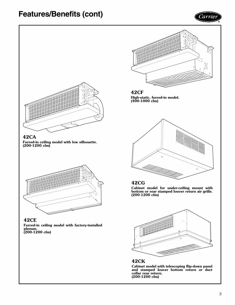
42CAFurred-in ceiling model with low silhouette.(200-1200 cfm)
42CEFurred-in ceiling model with factory-installedplenum.(200-1200 cfm)
42CFHigh-static, furred-in model.(400-1000 cfm)
42CGCabinet model for under-ceiling mount withbottom or rear stamped louver return air grille.(200-1200 cfm)
42CKCabinet model with telescoping flip-down paneland stamped louver bottom return or ductcollar rear return.(200-1200 cfm)
4
Features/Benefits (cont)
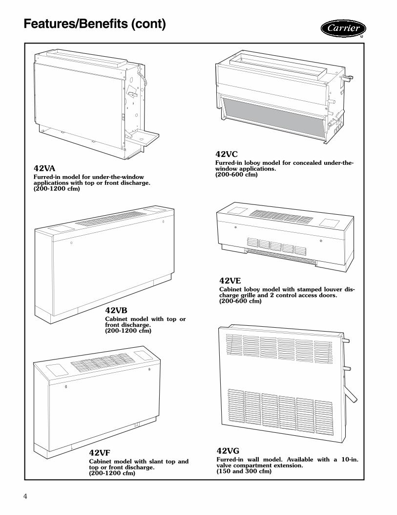
42VAFurred-in model for under-the-windowapplications with top or front discharge.(200-1200 cfm)
42VFCabinet model with slant top andtop or front discharge.(200-1200 cfm)
42VCFurred-in loboy model for concealed under-the-window applications.(200-600 cfm)
42VECabinet loboy model with stamped louver dis-charge grille and 2 control access doors.(200-600 cfm)
42VGFurred-in wall model. Available with a 10-in.valve compartment extension.(150 and 300 cfm)
42VBCabinet model with top orfront discharge.(200-1200 cfm)
5
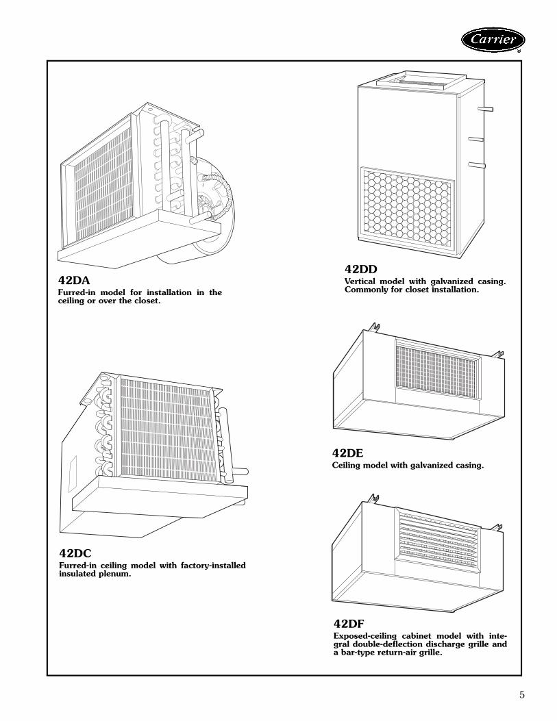
42DAFurred-in model for installation in theceiling or over the closet.
42DDVertical model with galvanized casing.Commonly for closet installation.
42DECeiling model with galvanized casing.
42DFExposed-ceiling cabinet model with inte-gral double-deflection discharge grille anda bar-type return-air grille.
42DCFurred-in ceiling model with factory-installedinsulated plenum.
6
Features/Benefits (cont)
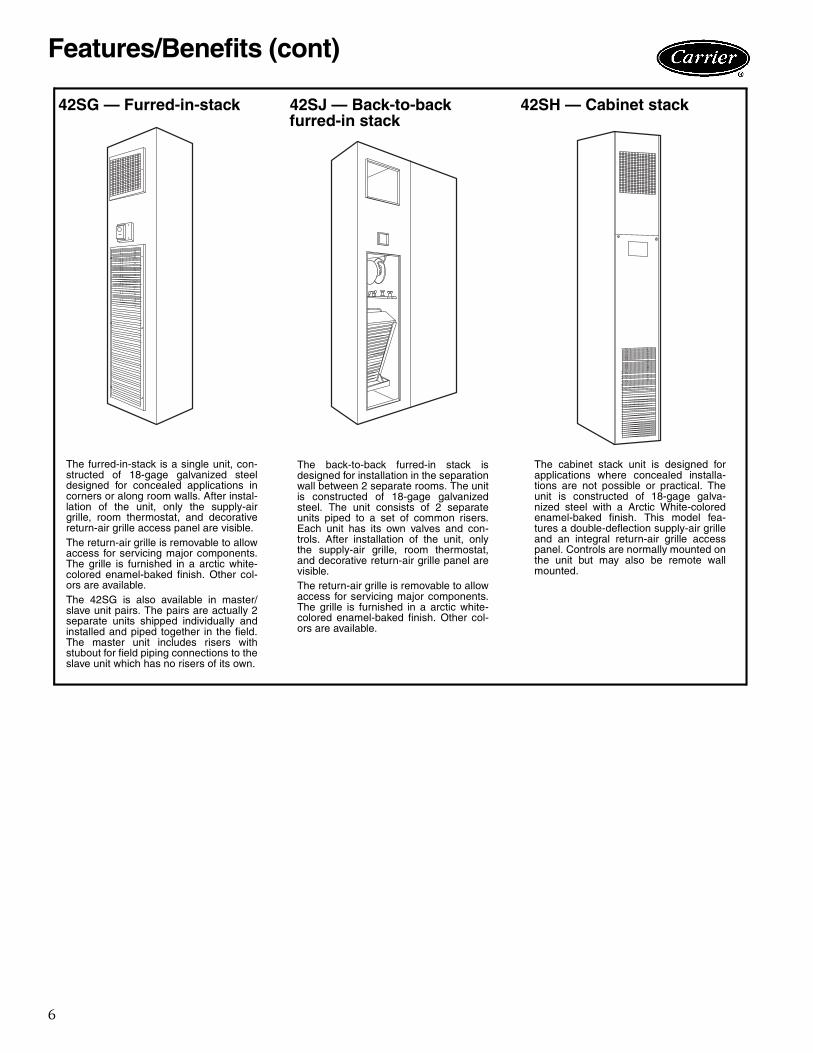
42SG — Furred-in-stack 42SJ — Back-to-backfurred-in stack
42SH — Cabinet stack
The furred-in-stack is a single unit, con-structed of 18-gage galvanized steeldesigned for concealed applications incorners or along room walls. After instal-lation of the unit, only the supply-airgrille, room thermostat, and decorativereturn-air grille access panel are visible.The return-air grille is removable to allowaccess for servicing major components.The grille is furnished in a arctic white-colored enamel-baked finish. Other col-ors are available.The 42SG is also available in master/slave unit pairs. The pairs are actually 2separate units shipped individually andinstalled and piped together in the field.The master unit includes risers withstubout for field piping connections to theslave unit which has no risers of its own.
The back-to-back furred-in stack isdesigned for installation in the separationwall between 2 separate rooms. The unitis constructed of 18-gage galvanizedsteel. The unit consists of 2 separateunits piped to a set of common risers.Each unit has its own valves and con-trols. After installation of the unit, onlythe supply-air grille, room thermostat,and decorative return-air grille panel arevisible.The return-air grille is removable to allowaccess for servicing major components.The grille is furnished in a arctic white-colored enamel-baked finish. Other col-ors are available.
The cabinet stack unit is designed forapplications where concealed installa-tions are not possible or practical. Theunit is constructed of 18-gage galva-nized steel with a Arctic White-coloredenamel-baked finish. This model fea-tures a double-deflection supply-air grilleand an integral return-air grille accesspanel. Controls are normally mounted onthe unit but may also be remote wallmounted.
7
Factory-installed optionsCoils — Choice of a 2-pipe or 4-pipe system with the fol-lowing chilled/hot water coil configurations:• 2-Row Coil (42VC, VE, VG only)• 3-Row Coil - 42C, D, V, S• 4-Row Coil - 42D, S• 4-Row High Capacity - 42V, C, S• 3-Row High Capacity - 42VC, VE• 3/1 Opposite End Coil Connections - 42C series,
42VA, 42VB, 42VF• 3/1 Same End Coil Connections - 42C series, 42VA,
42VB, 42VF, 42S• 2/1 Same End Coil Connection - 42VC, VE• 3/2 Opposite End Coil Connections - 42C series,
42VA, 42VB, 42VF, 42S• 3/2 Same End Coil Connection - 42C series, 42VA,
42VB, 42VF• 4/1 Opposite End Connections - 42D• 4/1 Same End Connections - 42D, 42S• 4/1 High Capacity Opposite End Coil - 42C series,
42VA, 42VB, 42VF• 4/1 High Capacity Same End Coil - 42C series, 42VA,
42VB, 42VF• 4/2 Same End Coil Connections - 42D• 4/2 Opposite End Connections - 42D• 6-Row High Capacity Coil - 42D• 6/1 Opposite End Connection - 42DA, DC, DE, DF• 6/1 Same End Connection - 42DA, DC, DE, DF• 6/2 Opposite End Connections - 42DA, DC, DE, DF• 6/2 Same End Connection - 42DA, DC, DE, DFDecorator colors — A wide variety of colors (Cham-pagne Beige, Toffee Brown, Ermine Grey, and PolarWhite) are available to match any interior décor. Select adesired color from a paint chip chart, Catalog number842-011, or provide paint chip for matching. Standardcolor is now Arctic White; the other colors require a specialquote. Decorative colors may be applied to:• Cabinet of 42VB, VF, VE, VG• Cabinet of 42CG• Panels 42S• Bottom Panels of 42CK• Wall Panels of 42VA• Cabinet 42DFElectric heaters — Coils are of high grade single-phase,nichrome resistance wire, insulated by ceramic insulators inplated steel brackets. Heater sizes available are shown inthe application data section for the respective units. Notavailable on 42VG units.Filters — Each unit (except the 42CA, VG unit) includes afiberglass throwaway filter sized for low velocity and maxi-mum efficiency. The standard option will filter both return-and outside-air. Optional permanent aluminum filters withcleanable, non-aluminum filter media are available for42CE, CF, CG, CK, DC, DD, DE, all 42V series, and all42S series units.Manual air vents — Each standard coil includes a man-ual air vent to allow venting at the coil if necessary forquick, complete air elimination.
Outside-air opening/damper — Damper is adjustablefrom 0 to 25% and provides ventilation air to unit. (Avail-able on 42VA, VB, VF and 42S series units.)Single power source connection — Provides factory-installed junction box to allow use of single power sourcefor motor and heater when they are of the same voltage.For 42D and 42S series units.Stamped toe space return-air grille — (42VB,VF units.)Tamperproof “Camloc” fasteners — Camloc fasten-ers are installed on the access panels and are available forall cabinet model units.Thermostat control packages — The standard ther-mostat control option is line voltage. Unit-Mounted linevoltage and 24V thermostats are available on the 42Vseries units. For thermostat control package options referto pages 10-12.
Field-installed accessoriesAutomatic air vents — Automatic air vents have fiberwashers which allow air in the pipes to pass through, auto-matically bleeding the system, and eliminating the need tomanually remove air from the system. When wet, washersswell and seal the system.Decorative wall panels — Wall panels are available foruse with fully recessed 42VA units.Drip lips (removable drain extension) — Drip lips arefrequently used when valves are added after unit installa-tion and space limitations will not permit use of anextended drain pan. The drip lip is placed on the end ofthe drain pan and is pitched toward the pan to ensureproper drainage. The drip lip gives positive control of con-densate from valves and controls on 42DA, DC units (avail-able as an option on 42DE, DF units). Provided as standardon these units when factory-supplied motorized valve pack-age is ordered. The drip lip is also installed on the 42Cseries ceiling fan coil units when 2-way or 3-way motorizedvalve packages are ordered. Panels, frames, and grilles — Panels, frames, andgrilles on the 42S series units can be chosen in a wide vari-ety of combinations to suit room decorating requirementsand allow access to the unit for maintenance. Dischargegrilles are double deflection type, aluminum finish orpainted. Return-air access panels containing return-airgrilles are available in five different types as illustrated onpage 97.
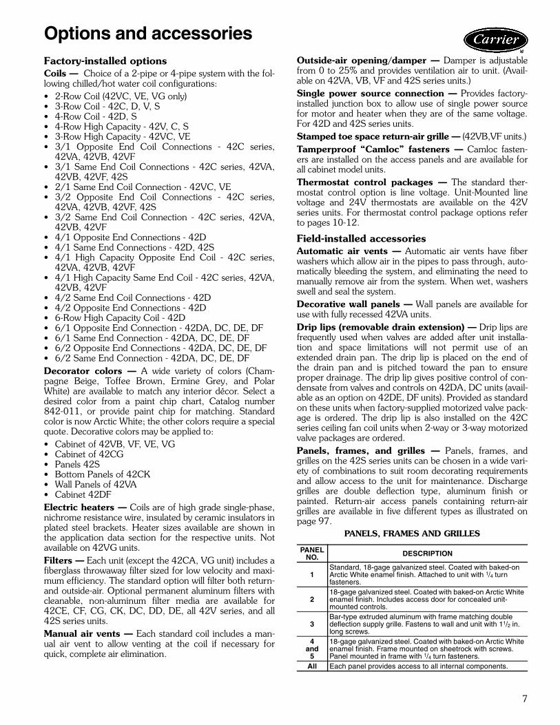
PANELS, FRAMES AND GRILLES
PANELNO. DESCRIPTION
1Standard, 18-gage galvanized steel. Coated with baked-onArctic White enamel finish. Attached to unit with 1/4 turnfasteners.
218-gage galvanized steel. Coated with baked-on Arctic Whiteenamel finish. Includes access door for concealed unit-mounted controls.
3Bar-type extruded aluminum with frame matching doubledeflection supply grille. Fastens to wall and unit with 11/2 in.long screws.
4and
5
18-gage galvanized steel. Coated with baked-on Arctic Whiteenamel finish. Frame mounted on sheetrock with screws.Panel mounted in frame with 1/4 turn fasteners.
All Each panel provides access to all internal components.
Options and accessories

8
Return-air grilles — Stamped-type return-air grilles arestandard on 42C, V, S units. Anodized aluminum hingedbar-type grilles are installed on 42CG, CK and DF (avail-able as an option on 42DA, DC, DE, DD) units.Risers — The 42S series units can accommodate ¾-in.(supply and return) and 1-in. (drain) to 2½-in. riser sizes in2-pipe systems. For other applications, such as reversereturn risers or 4-pipe systems, it may be necessary toaccommodate the additional risers.Condensate drains are available in sizes down to 1-in. forgreater cost economy. Riser size-reducers are factory-installed and for risers of over 115-in. length, filler piecescan be furnished for field installation.Riser expansion — When necessary, the 42S seriesunits are provided with factory-installed expansion loops.These expansion loops provide up to 1 ½-in. of riserexpansion within the standard unit construction. Thismeans that the unit can be used on installations of up to 20floors without any additional expansion devices.Risers material and insulation — The 42S series unitfactory-installed supply, return, and drain risers can be fur-nished in type M or L copper. All factory-furnished risersare insulated with flexible closed foam insulation in ½-in. or¾-in. thickness.Supply-air grilles — Two types of double deflectionsupply-air grilles are available for horizontal and verticalunits; an integral steel grille painted to match the unit or aseparate unpainted anodized aluminum grille. Not applica-ble to 42VG units.Tell-tale drain pan — A secondary drain connection islocated above the primary drain to act as a “tell-tale” in theevent that the primary drain becomes obstructed. They canbe applied to either the main drain pan or an extendedmain drain pan. This option only available on the 42C,42V (except 42VG), and 42DA, DC, DE, DF.Thermostats control packages — The standard ther-mostat control option is line voltage. Wall-mounted linevoltage and 24-v thermostats are available on the 42 seriesfan coil units. 24-v thermostat is not available on the42VC,VE,VG unit. Thermostat control packages optionsrefer to page 10-12.
Trim strips — Strips are available for use with partiallyrecessed vertical 42VA units and 42S only.Wall boxes — Wall boxes are all aluminum with insectscreen behind louvers. The wall boxes are available on all42V series units except the 42VG units.
Options and accessories (cont)
DRIP LIP(Horizontal Unit)
“TELL-TALE” DRAIN PAN(Horizontal Unit)
9
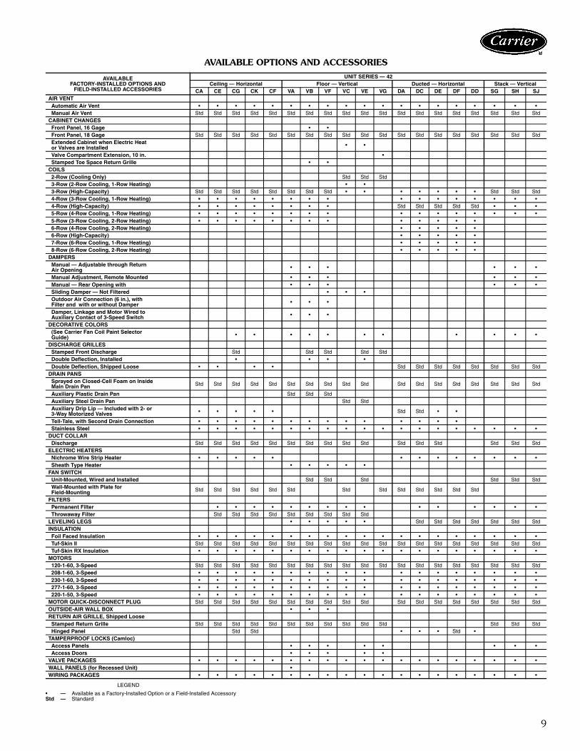
AVAILABLE OPTIONS AND ACCESSORIES
LEGEND
AVAILABLEFACTORY-INSTALLED OPTIONS AND
FIELD-INSTALLED ACCESSORIES
UNIT SERIES — 42Ceiling — Horizontal Floor — Vertical Ducted — Horizontal Stack — Vertical
CA CE CG CK CF VA VB VF VC VE VG DA DC DE DF DD SG SH SJAIR VENTAutomatic Air Vent • • • • • • • • • • • • • • • • • • •Manual Air Vent Std Std Std Std Std Std Std Std Std Std Std Std Std Std Std Std Std Std Std
CABINET CHANGESFront Panel, 16 Gage • •Front Panel, 18 Gage Std Std Std Std Std Std Std Std Std Std Std Std Std Std Std Std Std Std StdExtended Cabinet when Electric Heator Valves are Installed • •
Valve Compartment Extension, 10 in. •Stamped Toe Space Return Grille • •
COILS2-Row (Cooling Only) Std Std Std3-Row (2-Row Cooling, 1-Row Heating) • •3-Row (High-Capacity) Std Std Std Std Std Std Std Std • • • • • • • Std Std Std4-Row (3-Row Cooling, 1-Row Heating) • • • • • • • • • • • • • • • •4-Row (High-Capacity) • • • • • • • • Std Std Std Std Std • • •5-Row (4-Row Cooling, 1-Row Heating) • • • • • • • • • • • • • • • •5-Row (3-Row Cooling, 2-Row Heating) • • • • • • • • • • • • •6-Row (4-Row Cooling, 2-Row Heating) • • • • •6-Row (High-Capacity) • • • • •7-Row (6-Row Cooling, 1-Row Heating) • • • • •8-Row (6-Row Cooling, 2-Row Heating) • • • • •
DAMPERSManual — Adjustable through ReturnAir Opening • • • • • •
Manual Adjustment, Remote Mounted • • • • • •Manual — Rear Opening with • • • • • •Sliding Damper — Not Filtered • • •Outdoor Air Connection (6 in.), withFilter and with or without Damper • • •
Damper, Linkage and Motor Wired toAuxiliary Contact of 3-Speed Switch • • •
DECORATIVE COLORS(See Carrier Fan Coil Paint SelectorGuide) • • • • • • • • • • •
DISCHARGE GRILLESStamped Front Discharge Std Std Std Std StdDouble Deflection, Installed • • • •Double Deflection, Shipped Loose • • • • Std Std Std Std Std Std Std Std
DRAIN PANSSprayed on Closed-Cell Foam on InsideMain Drain Pan Std Std Std Std Std Std Std Std Std Std Std Std Std Std Std Std Std Std
Auxiliary Plastic Drain Pan Std Std StdAuxiliary Steel Drain Pan Std StdAuxiliary Drip Lip — Included with 2- or3-Way Motorized Valves • • • • • Std Std • •
Tell-Tale, with Second Drain Connection • • • • • • • • • • • • • •Stainless Steel • • • • • • • • • • • • • • • • • • •
DUCT COLLARDischarge Std Std Std Std Std Std Std Std Std Std Std Std Std Std Std Std
ELECTRIC HEATERSNichrome Wire Strip Heater • • • • • • • • • • • • •Sheath Type Heater • • • • •
FAN SWITCHUnit-Mounted, Wired and Installed Std Std Std Std Std StdWall-Mounted with Plate forField-Mounting Std Std Std Std Std Std Std Std Std Std Std Std Std
FILTERSPermanent Filter • • • • • • • • • • • • • • •Throwaway Filter Std Std Std Std Std Std Std Std Std
LEVELING LEGS • • • • • Std Std Std Std Std Std StdINSULATIONFoil Faced Insulation • • • • • • • • • • • • • • • • • • •Tuf-Skin II Std Std Std Std Std Std Std Std Std Std Std Std Std Std Std Std Std Std StdTuf-Skin RX Insulation • • • • • • • • • • • • • • • • • • •
MOTORS120-1-60, 3-Speed Std Std Std Std Std Std Std Std Std Std Std Std Std Std Std Std Std Std Std208-1-60, 3-Speed • • • • • • • • • • • • • • • • • •230-1-60, 3-Speed • • • • • • • • • • • • • • • • • •277-1-60, 3-Speed • • • • • • • • • • • • • • • • • •220-1-50, 3-Speed • • • • • • • • • • • • • • • • • •
MOTOR QUICK-DISCONNECT PLUG Std Std Std Std Std Std Std Std Std Std Std Std Std Std Std Std Std StdOUTSIDE-AIR WALL BOX • • •RETURN AIR GRILLE, Shipped LooseStamped Return Grille Std Std Std Std Std Std Std Std Std Std Std Std Std StdHinged Panel Std Std • • • Std •
TAMPERPROOF LOCKS (Camloc)Access Panels • • • • • • • •Access Doors • • • • •
VALVE PACKAGES • • • • • • • • • • • • • • • • • • •WALL PANELS (for Recessed Unit) •WIRING PACKAGES • • • • • • • • • • • • • • • • • • •
• — Available as a Factory-Installed Option or a Field-Installed AccessoryStd — Standard

10
Use the Control Selection guide to make sure that allnecessary components are provided for and that the com-ponents are compatible with the required control system.
NOTE: When thermostatic fan control is selected or whenunit outside air dampers are used, unit-mounted thermo-stats are not recommended as their use will result in poorroom temperature sensing.
CONTROL SELECTION GUIDE
*If system is HEATING-ONLY or COOLING-ONLY, no changeover or bypass is required.
NOTE: Unit-mounted thermostats are not recommended with either fan-cycle control or applications with outside air dampers.
SYSTEM DESCRIPTION THERMOSTATCHANGEOVER
ONSUPPLY PIPE
VALVE FANSWITCH (SW) NOTES
2-P
IPE
HE
AT
ING
-CO
OL
ING
*
FanControl(2-Pipe)
Fan manually cycled None None None Standard 3-SpeedSW
Not recommendedfor high humidityapplicationThermostat cycles fan on-off
from speed set with fan switch.Wall mounted includesheat-cool switch.
None None Thermostat has inte-gral 3-Speed SW
Thermostat cycles fan on-offfrom fan speed set with switch.Mode automatically switchedby changeover sensing watertemp.
Wall mounted.Heating/coolingThermostat
Yes None Standard3-Speed SW
Unit-mounted thermostatsprovide very poor roomtemperature control
Thermostat cycles fan fromhigh to low on cooling and lowto off on heating.
Wall or unit mounted Yes None No Standard 3-SpeedSwitch, ON-OFF tog-gle SW only
Best fan cycle control forhigh humidity applications
Two-positionelectricvalves(2-pipe)
Thermostat cycles valveopen or closed.
Wall mounted includesheat-cool switch.
None Motorized (N.C.)3-way or 2-way,no bypass required.
Thermostat has inte-gral 3-Speed SW
Valve packages with belledend(s) for field soldering tocoil.
Thermostat cycles valveopen or closed. Mode auto-matically switched bychangeover sensing watertemp.
Wall or unit mounted.Heating/coolingThermostat
Yes Motorized (N.C.)3-way or 2-way
Standard 3-SpeedSW. Others have ther-mostats with integral3-Speed SW
EL
EC
TR
ICH
EA
T
Two-positionelectricvalve withAuxiliaryElectricHeat(2-pipe)
Thermostat cycles valveopen or closed. 2° F aftervalve closes, thermostatactivates electric heater.Heater cannot turn on if hotwater is in coil.
Wall or unit mounted.Sequenced heatingand cooling.
Yes.Two Required.
Motorized 3-way or2-way
Standard 3-SpeedSW. Others have ther-mostats with integral3-Speed SW
Valve packages with belledend(s) for field soldering tocoil.
Thermostat cycles valveopen or closed. Manualchangeover switch changesthermostat to heat to activateelectric heater.
Wall mountedincludes heat-coolswitch.
None Motorized 3-way or2-way, no bypassrequired
Thermostat has inte-gral 3-Speed SW
Valve packages with belledend(s) for field solderingto coil.
Two-positionelectricvalve withtotalelectricheat(2-pipe)
Thermostat cycles valveopen or closed. Manualchangeover switch changesthermostat to heat to activateelectric heater.
Wall mounted includesheat-cool switch.
None Motorized (N.C.)3-way or 2-way,no bypass required
Thermostat has inte-gral 3-Speed SW
Valve packages with belledend(s) for field solderingto coil.
Thermostat cycles valveopen or closed. 2° F aftervalve closes, thermostat acti-vates electric heater.
Wall or unit mounted.Sequenced heatingand cooling
None Motorized (N.C.)3-way or 2-way,no bypass required
Standard 3-SpeedSW
4-P
IPE
Two-positionelectricvalves(4-pipe)
Thermostat cycles cooling andheating valves open or closed.
Wall mounted includessubbase with heat-cool switch.
None Motorized (N.C.)3-way or 2-way(requires 2 valves)
Thermostat has inte-gral 3-Speed SW
Valve packages with belledend(s) for field solderingto coil.
Thermostat cycles coolingvalve open or closed. 2° Fafter valve closes, thermostatcycles heating valve open orclosed.
Wall or unit mounted.Sequenced heatingand cooling.
None Motorized (N.C.)3-way or 2-way(requires 2 valves)
Standard 3-SpeedSW. Others havethermostats with inte-gral 3-Speed SW
Controls
11
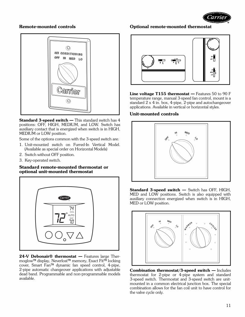
Remote-mounted controls
Standard 3-speed switch — This standard switch has 4positions: OFF, HIGH, MEDIUM, and LOW. Switch hasauxiliary contact that is energized when switch is in HIGH,MEDIUM or LOW position.Some of the options common with the 3-speed switch are:1. Unit-mounted switch on Furred-In Vertical Model.
(Available as special order on Horizontal Models)2. Switch without OFF position.3. Key-operated switch.
Standard remote-mounted thermostat or optional unit-mounted thermostat
24-V Debonair® thermostat — Features large Ther-moglow™ display, Neverlost™ memory, Exact Fit™ lockingcover, Smart Fan™ dynamic fan speed control, 4-pipe,2-pipe automatic changeover applications with adjustabledead band. Programmable and non-programmable modelsavailable.
Optional remote-mounted thermostat
Line voltage T155 thermostat — Features 50 to 90 Ftemperature range, manual 3-speed fan control, mount is astandard 2 x 4 in. box, 4-pipe, 2-pipe and autochangeoverapplications. Available in vertical or horizontal styles.
Unit-mounted controls
Standard 3-speed switch — Switch has OFF, HIGH,MED and LOW positions. Switch is also equipped withauxiliary connection energized when switch is in HIGH,MED or LOW position.
Combination thermostat/3-speed switch — Includesthermostat for 2-pipe or 4-pipe system and standard3-speed switch. Thermostat and 3-speed switch are unit-mounted in a common electrical junction box. The specialcombination allows for the fan coil unit to have control forthe valve cycle only.
COOL
HEAT
AUTO
R
OFF
HI MED
LO
OFF
HI MED
LO
12
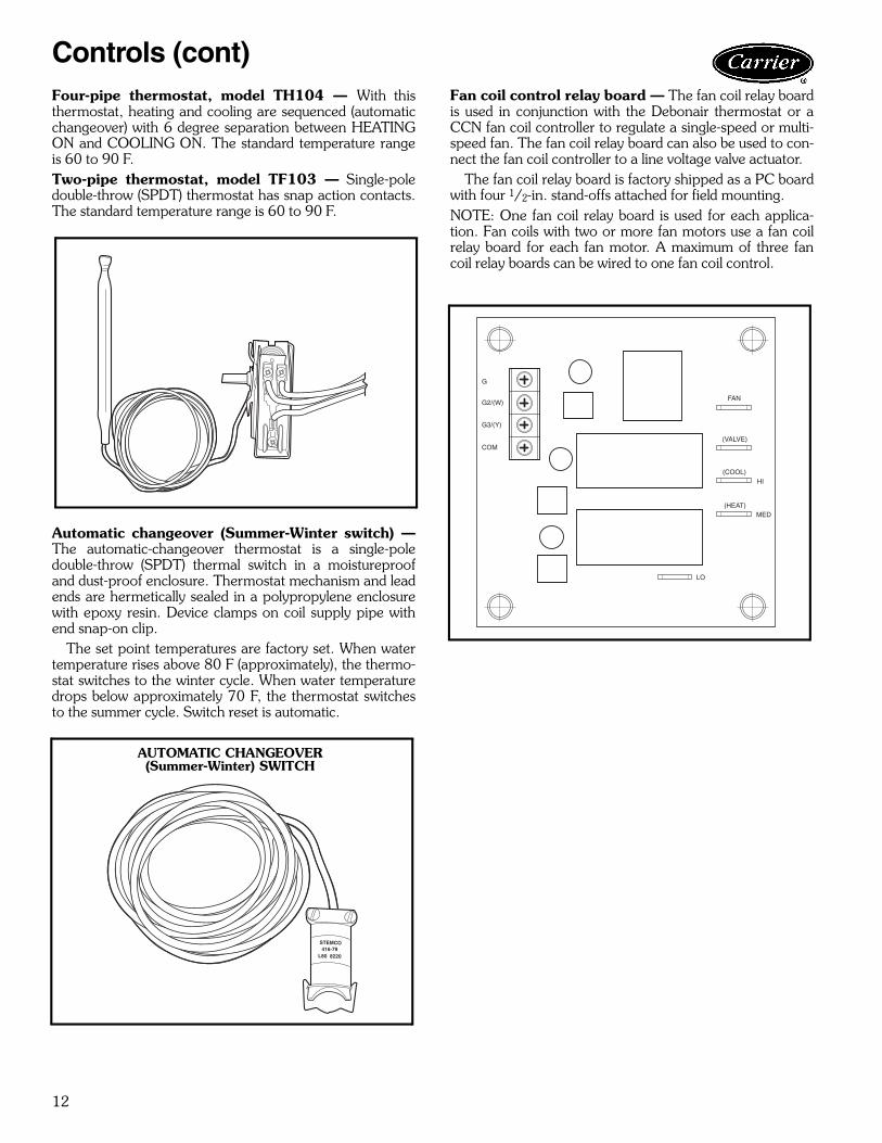
Four-pipe thermostat, model TH104 — With thisthermostat, heating and cooling are sequenced (automaticchangeover) with 6 degree separation between HEATINGON and COOLING ON. The standard temperature rangeis 60 to 90 F.Two-pipe thermostat, model TF103 — Single-poledouble-throw (SPDT) thermostat has snap action contacts.The standard temperature range is 60 to 90 F.
Automatic changeover (Summer-Winter switch) —The automatic-changeover thermostat is a single-poledouble-throw (SPDT) thermal switch in a moistureproofand dust-proof enclosure. Thermostat mechanism and leadends are hermetically sealed in a polypropylene enclosurewith epoxy resin. Device clamps on coil supply pipe withend snap-on clip.
The set point temperatures are factory set. When watertemperature rises above 80 F (approximately), the thermo-stat switches to the winter cycle. When water temperaturedrops below approximately 70 F, the thermostat switchesto the summer cycle. Switch reset is automatic.
Fan coil control relay board — The fan coil relay boardis used in conjunction with the Debonair thermostat or aCCN fan coil controller to regulate a single-speed or multi-speed fan. The fan coil relay board can also be used to con-nect the fan coil controller to a line voltage valve actuator.
The fan coil relay board is factory shipped as a PC boardwith four 1/2-in. stand-offs attached for field mounting.NOTE: One fan coil relay board is used for each applica-tion. Fan coils with two or more fan motors use a fan coilrelay board for each fan motor. A maximum of three fancoil relay boards can be wired to one fan coil control.
Controls (cont)
STEMCO416-79
L80 8220
AUTOMATIC CHANGEOVER(Summer-Winter) SWITCH
G
G2/(W)
G3/(Y)
COM
FAN
(VALVE)
(COOL)HI
(HEAT)MED
LO

13
Basic definitionsUnit hand — When facing the supply air outlet from thefront of the unit (air blowing in your face), your right handwill be the right hand side of the unit and your left hand theleft hand side of the unit.
Same end connection (2 pipe or 4 pipe) — All pipingconnections are on the same end (side) of the unit. Con-trols and electrical connection will be on the end (side)opposite the piping connection.
Standard 2-pipe units will be the same end connection.
Opposite end connection (4-pipe option) — Hotwater (HW) piping connections and electrical will be on theend (side) opposite the chilled water (CW) and drainconnections.
Application data
UNIT HAND
SAME END CONNECTION
NOTE: Piping determines the hand of the unit.
OPPOSITE END CONNECTION
NOTE: Chilled water piping determines the hand of the unit.

14
System pipingThe following diagrams show some common methodsused to pipe the 42S series units. Only the 2-pipe systemsare shown; however, the methods would be the same for4-pipe systems.System 1, the “direct return” system, is the most common.It is economical to install since it supplies and returns thewater for a riser column from the same location, at the topor the bottom of a building. This type of riser arrangementdoes require more attention to individual unit water flowbalancing. The risers are normally capped at the end asshown in the diagrams.System 2, the “reverse return” system, is used to minimizethe requirement for individual unit balancing. This systemis usually referred to as the self-balancing system. Thearrangement of the risers allows the water flow for eachunit in a column to be equalized. In the reverse return sys-tem both the supply and return mains are located at thetop or the bottom of a building requiring an additionalreturn riser to be furnished in the units.System 3, the “common reverse return” system, typicallyhas the supply and return mains located remotely fromeach other — such as one at the top and one at the bottomof a building. This eliminates the need for a reverse returnriser in the units.
Application data (cont)
SYSTEM 1 — DIRECT RETURN
SYSTEM 2 — REVERSE RETURN
SYSTEM 3 — COMMON REVERSE RETURN

15
RisersRiser diameter is an important consideration in the designof stack series systems. Standard units can accommodate3/4-in. to 21/2-in. riser sizes in 2-pipe systems. For otherapplications, such as reverse return risers or 4-pipe sys-tems, it may be necessary to accommodate the additionalrisers.
Riser size is based on the water flow needed for a giventier of units. Unit risers are sized according to the diameterand length requirements as specified by the customer. Todetermine riser size, water velocity should be limited to 5 to8 ft/second. Thus, if 10 units are to be stacked verticallywith each unit requiring 3 gpm, the maximum flow in therisers is 30 gpm. Through 11/4 in. risers, this is a velocityof 7.5 ft/second. The maximum flow rate of 30 gpmoccurs only at the supply and return points. As the watermoves upward, the flow in the supply riser is reduced by3 gpm per floor, so that after 3 floors, the total flow is21 gpm and riser size can be reduced to one inch. Seechart on page 103.
Condensate drains are available in sizes down to oneinch for greater first cost economy.
Riser size-reducers are factory installed and caps are pro-vided at customer request.
For risers of over 115 in. length, filler pieces can be fur-nished for field installation.
Typical arrangementsTypical arrangement applications for each model type areshown below. The fan coil units feature almost an unlim-ited number of arrangements to meet the needs of newconstruction, renovation, or reconstruction. Consult thefactory for the arrangement (standard or special) to meetyour particular need.
42SH — EXPOSED CABINET
42SG — FURRED-IN STACK 42SG — FURRED-IN STACK MASTER/SLAVE UNIT
42SJ — BACK-TO-BACK FURRED-IN STACK

16
PIPING COMPONENTS
LEGEND
*Check all system component pressure ratings (coils, values, pumps,etc.) with manufacturer and any applicable local or national pipingcodes prior to specifying system pressure rating.
SYMBOL/SKETCH DESCRIPTIONCV FACTOR RATING* STEAM
USE1/2 3/4 PSI FMANUAL AIR VENT: Threaded brass needlevalve with screwdriver slot for adjustment.Application — Body brazed into high point ofheating and cooling coils for bleeding air fromcoil. Standard item on all hydronic coils (notused on steam or DX coils). Should not beused in lieu of main system air vents.
N/A N/A 400 100 NO
AUTOMATIC AIR VENT: Nickel plated brassvalve, fiber-disc type, with positive shut-offballcheck and quick vent feature via knurledvent screw.Application — Optional replacement for man-ual air vent. Automatically passes minutequantities of air through the fiber discs whichexpand upon contact with water, completelysealing the valve. As air accumulates, the fiberdiscs dry and shrink, repeating the cycle. Notrecommended for removing large quantities ofair encountered during initial start-up or subse-quent draining and refilling. Should not beused in lieu of main system air vents.
N/A N/A 125 240 NO
SWAGE: Copper tube end expanded to accepta copper tube of the same size for factory orfield brazing.Application — Used where possible for all tub-ing joints for best joint integrity.
N/A N/A 300 200 YES
UNION: Combination wrought copper/castbrass union assembly, solder by solder.Application — Used for quick connect (and dis-connect) of valve package components to min-imize field labor and facilitate servicing of unit.
N/A N/A 300 200 YES
INSERTION TEST PORT: Brass body valvefor acceptance of test probe (up to 1/8 in.diameter).Application — Installed on one (or both) sidesof the coil to allow for temperature or pressuresensing. Used for close tolerance water bal-ancing and service analysis.
N/A N/A 250 250 NO
Cv — Coefficient of VelocityDX— Direct Expansion
Application data (cont)
17
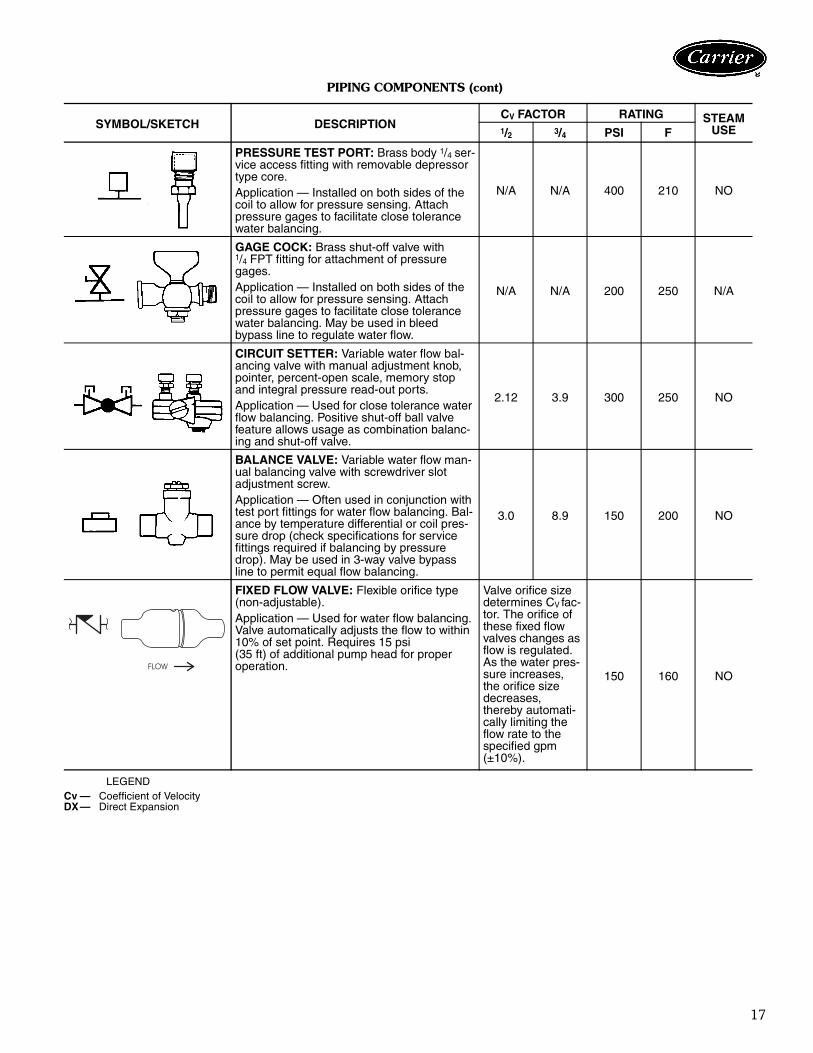
PIPING COMPONENTS (cont)
LEGEND
SYMBOL/SKETCH DESCRIPTIONCV FACTOR RATING STEAM
USE1/2 3/4 PSI F
PRESSURE TEST PORT: Brass body 1/4 ser-vice access fitting with removable depressortype core.Application — Installed on both sides of thecoil to allow for pressure sensing. Attachpressure gages to facilitate close tolerancewater balancing.
N/A N/A 400 210 NO
GAGE COCK: Brass shut-off valve with1/4 FPT fitting for attachment of pressuregages.Application — Installed on both sides of thecoil to allow for pressure sensing. Attachpressure gages to facilitate close tolerancewater balancing. May be used in bleedbypass line to regulate water flow.
N/A N/A 200 250 N/A
CIRCUIT SETTER: Variable water flow bal-ancing valve with manual adjustment knob,pointer, percent-open scale, memory stopand integral pressure read-out ports.Application — Used for close tolerance waterflow balancing. Positive shut-off ball valvefeature allows usage as combination balanc-ing and shut-off valve.
2.12 3.9 300 250 NO
BALANCE VALVE: Variable water flow man-ual balancing valve with screwdriver slotadjustment screw.Application — Often used in conjunction withtest port fittings for water flow balancing. Bal-ance by temperature differential or coil pres-sure drop (check specifications for servicefittings required if balancing by pressuredrop). May be used in 3-way valve bypassline to permit equal flow balancing.
3.0 8.9 150 200 NO
FIXED FLOW VALVE: Flexible orifice type(non-adjustable).Application — Used for water flow balancing.Valve automatically adjusts the flow to within10% of set point. Requires 15 psi(35 ft) of additional pump head for properoperation.
Valve orifice sizedetermines CV fac-tor. The orifice ofthese fixed flowvalves changes asflow is regulated.As the water pres-sure increases,the orifice sizedecreases,thereby automati-cally limiting theflow rate to thespecified gpm(±10%).
150 160 NO
Cv — Coefficient of VelocityDX— Direct Expansion
����
18
PIPING COMPONENTS (cont)
LEGEND
SYMBOL/SKETCH DESCRIPTIONCV FACTOR RATING STEAM
USE1/2 3/4 PSI F
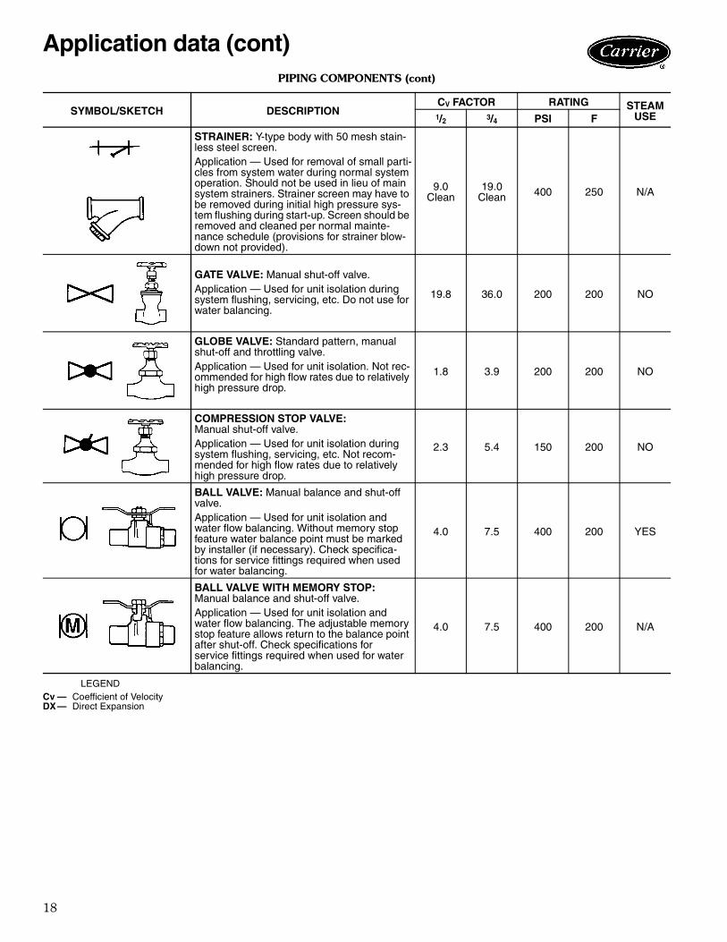
STRAINER: Y-type body with 50 mesh stain-less steel screen.Application — Used for removal of small parti-cles from system water during normal systemoperation. Should not be used in lieu of mainsystem strainers. Strainer screen may have tobe removed during initial high pressure sys-tem flushing during start-up. Screen should beremoved and cleaned per normal mainte-nance schedule (provisions for strainer blow-down not provided).
9.0Clean
19.0Clean 400 250 N/A
GATE VALVE: Manual shut-off valve.Application — Used for unit isolation duringsystem flushing, servicing, etc. Do not use forwater balancing.
19.8 36.0 200 200 NO
GLOBE VALVE: Standard pattern, manualshut-off and throttling valve.Application — Used for unit isolation. Not rec-ommended for high flow rates due to relativelyhigh pressure drop.
1.8 3.9 200 200 NO
COMPRESSION STOP VALVE:Manual shut-off valve.Application — Used for unit isolation duringsystem flushing, servicing, etc. Not recom-mended for high flow rates due to relativelyhigh pressure drop.
2.3 5.4 150 200 NO
BALL VALVE: Manual balance and shut-offvalve.Application — Used for unit isolation andwater flow balancing. Without memory stopfeature water balance point must be markedby installer (if necessary). Check specifica-tions for service fittings required when usedfor water balancing.
4.0 7.5 400 200 YES
BALL VALVE WITH MEMORY STOP:Manual balance and shut-off valve.Application — Used for unit isolation andwater flow balancing. The adjustable memorystop feature allows return to the balance pointafter shut-off. Check specifications forservice fittings required when used for waterbalancing.
4.0 7.5 400 200 N/A
Cv — Coefficient of VelocityDX— Direct Expansion
Application data (cont)

19
PIPING COMPONENTS (cont)
LEGEND
NOTES:1. Motorized 2-way valves have a maximum close-off differential of 25 psi.2. Motorized 3-way valves have a maximum close-off differential of 10 psi.
SYMBOL/SKETCH DESCRIPTIONCV FACTOR RATING STEAM
USE1/2 3/4 PSI F
2-WAY MOTORIZED VALVE: Electric 2-posi-tion flow control valve (open/closed). Normallyclosed body with manual override lever.Installed in supply line to unit.Application — All standard control and valvepackages are based upon normally closedvalves (valve electrically powered open andclosed by spring return when electric powerremoved). Manual override lever allows valveto be placed in the open position for second-ary (unit) flushing, constant water flow prior tostart-up, etc. Manual override is automaticallydisengaged when valve is electrically acti-vated. Consult factory for normally openvalve applications.
2.3 2.3 300 200
YES15PSI
MAX.
3-WAY MOTORIZED VALVE: Electric2-position flow control valve (closed to coil/open to bypass or open to coil/closed tobypass). Normally closed with manual over-ride lever. Installed in supply line to unit.Application — Same comments as 2-waymotorized valve except with manual overridelever engaged the valve is open to both portsand water flow will take the path of least resis-tance through the valve package (not neces-sarily 100% through the coil).
5.0 5.0
300 200 N/A
SERVICE
2.8 2.8
BYPASS
MODULATING VALVE(Non-Spring Return): Modulating valves aredesigned to control the flow in the circuit bymaking incremental adjustments to the flowpath within the valve.Application — To control fluid flow in fan coilunits.
4.0 300 200 N/A
MODULATING VALVE(Spring Return): Modulating valves aredesigned to control the flow in the circuit bymaking incremental adjustments to the flowpath within the valve.Application — Same comments as non-springreturn except when powered, the actuatormoves to the desired position, at the sametime tensing the spring return system. Whenpower is removed for more than two minutesthe spring returns the actuator to the normalposition.
4.0 300 200 N/A
AQUASTAT: Water temperature sensing elec-trical switch.Application — Clips directly on nominalsize 1/2 in. or 3/4 in. copper tubing for watertemperature sensing. Must be correctlylocated for proper control operation.
Cv — Coefficient of VelocityDX— Direct Expansion

20
Valve packagesThere are limitations on physical size of pneumatic valves,quantity and type of matching components, and requiredcontrol interface. See Symbols and Placement of Valvesdiagram.
Consult factory before ordering any special valve pack-age components that are not covered in this book.
Valve packages are shipped with the units or in unit car-tons. Valve packages include belled ends for field solderingto coil connections.
All factory-furnished cooling valve packages arearranged to position as much of the package as possibleover an auxiliary drain pan or drip lip. This helps minimizefield piping insulation requirements.
Application data (cont)
SYMBOLS AND PLACEMENT OF VALVES
Coil Connections (Positions A & B) — When isolation valve only is added to supply or return line, the isolation valve will be factorybrazed to the coil stub-out. Addition of any other component or connection to the supply or return line will change the respective coilconnection(s).Service Fittings (Positions C & D) — Optional fittings for attaching pressure/temperature sensing devices to obtain pressure drop or tem-perature differential across coil. Used with ball valve or balance valve where extremely accurate water flow balancing is required.Water Flow Balancing (Positions E, F, & H) — Only one device per total valve package to be used for balancing water flow through thecoil. When isolation valve (ball valve or ball valve with memory stop at position H) is used for water flow balancing, do not specify additionalbalancing device at position E or F. When balancing device is specified at position E or F, isolation valve does not require balancing featureat position H (with a 3-way motorized valve, a bypass balancing valve may be specified in the bypass line to permit equal flow balancing).Strainer (Position G) — Does not include blow down fitting and should not be used in lieu of main piping strainers.Isolation Valves (Positions H & J) — Normally requires one each on supply and return line (see exception under circuit setter). Whenposition H is used for balancing (ball valve or ball valve with memory stop), check specifications for service valve requirements.

21
LEGEND
*When aquastat is used for automatic changeover, bypass isrequired as indicated by dashed line.
NOTES:1. Packages factory furnished and installed.2. Valves are 5/8-in. ODS unless otherwise specified.3. If an automatic flow control valve is added, it will be located on
supply line between shutoff valve and coil (or motorized controlvalve, if supplied).
4. Packages 17-A,B,C,D,E,F,G,H,J,K,L,M,N and P are listed oncurrent price pages.
Ball Valve
Ball Valve with Memory Stop
Gate Shut Off Valve
Balancing Valve
Circuit Setter
Motorized 2-Way Valve
Motorized 3-Way Valve
M
M
M
VALVE PACKAGE ARRANGEMENTS

22
Application data (cont)
CV FACTOR:The flow rate in gallons per minute (gpm) through a piping component when the pressure drop (∆P) in pounds per square inch (psi)across the component is 1.0 (psi).
Pressure drop (ft-H2O) = 2.31 x psi (pressure drop)
GRAPH EXAMPLE:∆P for 2.0 gpm through a component with a CV of 1.0 is 4.0 psi x 2.31 = 9.24 ft-H2O
FORMULA EXAMPLE:
TOTAL PRESSURE DROP is the Sum of the pressure drop of all piping and components in the water flow path.
∆P (ft-H2O) =(gpm)2
x 2.31 =(2.0)2
x 2.31 = 9.24 ft-H2O(Cv)2 (1.0)2
Cv FACTOR VS WATER PRESSURE DROP
23
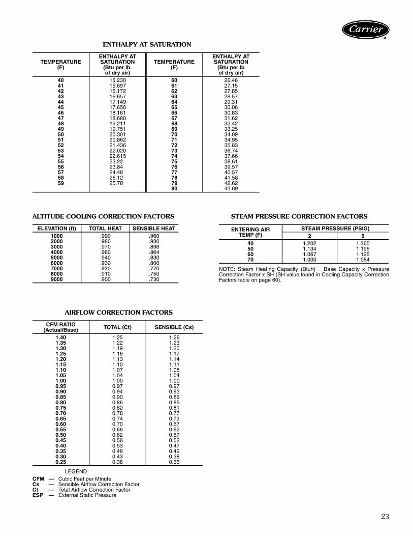
ENTHALPY AT SATURATION
ALTITUDE COOLING CORRECTION FACTORS STEAM PRESSURE CORRECTION FACTORS
NOTE: Steam Heating Capacity (Btuh) = Base Capacity x PressureCorrection Factor x SH (SH value found in Cooling Capacity CorrectionFactors table on page 60).
AIRFLOW CORRECTION FACTORS
LEGEND
TEMPERATURE(F)
ENTHALPY ATSATURATION(Btu per lb.of dry air)
TEMPERATURE(F)
ENTHALPY ATSATURATION
(Btu per lbof dry air)
40 15.230 60 26.4641 15.697 61 27.1542 16.172 62 27.8543 16.657 63 28.5744 17.149 64 29.3145 17.650 65 30.0646 18.161 66 30.8347 18.680 67 31.6248 19.211 68 32.4249 19.751 69 33.2550 20.301 70 34.0951 20.862 71 34.9552 21.436 72 35.8353 22.020 73 36.7454 22.615 74 37.6655 23.22 75 38.6156 23.84 76 39.5757 24.48 77 40.5758 25.12 78 41.5859 25.78 79 42.62
80 43.69
ELEVATION (ft) TOTAL HEAT SENSIBLE HEAT1000 .990 .9602000 .980 .9303000 .970 .8964000 .960 .8645000 .940 .8306000 .930 .8007000 .920 .7708000 .910 .7509000 .900 .730
ENTERING AIRTEMP (F)
STEAM PRESSURE (PSIG)2 5
40 1.202 1.26550 1.134 1.19660 1.067 1.12570 1.000 1.054
CFM RATIO(Actual/Base) TOTAL (Ct) SENSIBLE (Cs)
1.40 1.25 1.261.35 1.22 1.231.30 1.19 1.201.25 1.16 1.171.20 1.13 1.141.15 1.10 1.111.10 1.07 1.081.05 1.04 1.041.00 1.00 1.000.95 0.97 0.970.90 0.94 0.930.85 0.90 0.890.80 0.86 0.850.75 0.82 0.810.70 0.78 0.770.65 0.74 0.720.60 0.70 0.670.55 0.66 0.620.50 0.62 0.570.45 0.58 0.520.40 0.53 0.470.35 0.48 0.420.30 0.43 0.380.25 0.38 0.33
CFM — Cubic Feet per MinuteCs — Sensible Airflow Correction FactorCt — Total Airflow Correction FactorESP — External Static Pressure
24
Electric heatElectric heaters are available for installation on Carrier fancoil units in the following applications.Total electric heat — This system provides completeheating during the heating season; no boiler is required.Heating and cooling are now available on an individualbasis throughout the year with a 2-pipe system.
Chilled water is used for cooling and the electric heater isused for heating. Individual room controls can be suppliedfor either manual or automatic changeover.Auxiliary electric heat — This system is used for heat-ing between seasons or during the cooling season whenchilled water is being circulated. Individual room controlsare supplied to provide electric heat only when chilledwater is being circulated through the system. Water flowthrough the unit is shut off when the heater is turned on.
During the winter heating season, heating is provided byhot water circulated through the system. A changeoverdevice locks out the electric heat when the hot water iscirculated.
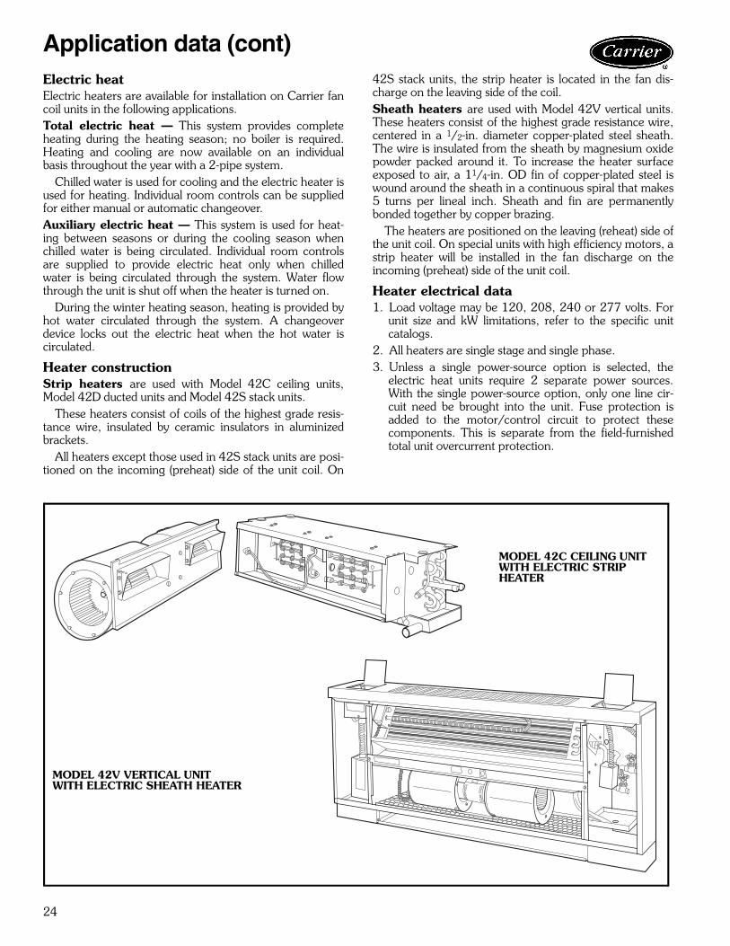
Heater constructionStrip heaters are used with Model 42C ceiling units,Model 42D ducted units and Model 42S stack units.
These heaters consist of coils of the highest grade resis-tance wire, insulated by ceramic insulators in aluminizedbrackets.
All heaters except those used in 42S stack units are posi-tioned on the incoming (preheat) side of the unit coil. On
42S stack units, the strip heater is located in the fan dis-charge on the leaving side of the coil.Sheath heaters are used with Model 42V vertical units.These heaters consist of the highest grade resistance wire,centered in a 1/2-in. diameter copper-plated steel sheath.The wire is insulated from the sheath by magnesium oxidepowder packed around it. To increase the heater surfaceexposed to air, a 11/4-in. OD fin of copper-plated steel iswound around the sheath in a continuous spiral that makes5 turns per lineal inch. Sheath and fin are permanentlybonded together by copper brazing.
The heaters are positioned on the leaving (reheat) side ofthe unit coil. On special units with high efficiency motors, astrip heater will be installed in the fan discharge on theincoming (preheat) side of the unit coil.
Heater electrical data1. Load voltage may be 120, 208, 240 or 277 volts. For
unit size and kW limitations, refer to the specific unitcatalogs.
2. All heaters are single stage and single phase.3. Unless a single power-source option is selected, the
electric heat units require 2 separate power sources.With the single power-source option, only one line cir-cuit need be brought into the unit. Fuse protection isadded to the motor/control circuit to protect thesecomponents. This is separate from the field-furnishedtotal unit overcurrent protection.
Application data (cont)
MODEL 42C CEILING UNITWITH ELECTRIC STRIP HEATER
MODEL 42V VERTICAL UNITWITH ELECTRIC SHEATH HEATER

25
42C SERIES
42V SERIES
NOTE: All heaters are single-stage and single-phase. Contact yourCarrier representative for heater availability for 220-1-50 units.
42D SERIES
NOTE: All heaters are single-stage and single-phase.
42S SERIES
HEATERVOLTAGE kW CAPACITY
(Btuh)UNIT SIZE
02 03 04 06 08 10 12
120
0.5 1,708 * *1.0 3,415 * * *1.5 5,123 * *2.0 6,830 * * * * * * *3.0 10,245 * * * *
208,240,277
0.5 1,708 * *1.0 3,415 * * *1.5 5,123 * *2.0 6,830 * * * * * * *3.0 10,245 * * * *4.0 13,660 * * * *5.0 17,075 * *6.0 20,490 * * * *8.0 27,320 * *
240,277 10.0 34,150 *
HEATERVOLTAGE kW CAPACITY
(Btuh)UNIT SIZE
02 03 04 06 08 10 12
120
0.5 1,708 * *1.0 3,415 * * * *1.5 5,123 * * *2.0 6,830 * * *3.0 10,245 * * * *
208,240,277
1.0 3,415 * * * *1.5 5,123 * * *2.0 6,830 * * *3.0 10,245 * * * *4.0 13,660 * * *5.0 17,075 * *
240,277 6.0 20,490 *
HEATERVOLTAGE kW CAPACITY
(Btuh)UNIT SIZE
06 08 10 12 14 16 18 20
1202.0 6,830 * * *3.0 10,245 * * *
208,240,277
2.0 6,830 * * *3.0 10,245 * * *4.0 13,660 * * * * * * * *5.0 17,075 * * * * * * *6.0 20,490 * * * * * * *7.0 23,905 * * * * * *8.0 27,320 * * * * *9.0 30,735 * * * * *
10.0 34,150 * * * *12.0 40,980 * * *14.0 47,810 *
HEATERVOLTAGE kW
UNIT SIZE03 04 06 08 10 12
120
1.0 * * * * * *1.5 * * * * * *2.0 * * * * * *3.0 * * * * * *
208
1.0 * * * * * *1.5 * * * * * *2.0 * * * * * *3.0 * * * * * *4.0 * * * * *5.0 * * * *6.0 * * *8.0 * * *
240,277
1.0 * * * * * *1.5 * * * * * *2.0 * * * * * *3.0 * * * * * *4.0 * * * * *5.0 * * * *6.0 * * *8.0 * * *
10.0 * *
26
Refer to the Carrier Electronic Selection Program for infor-mation to determine unit sizing for your needs. The follow-ing selection procedure applies to all Carrier 42 seriesunits and may be used as a guide to determine unitperformance.FORMULASTC = TCb x Ct x Et
SC = SCb x Cs x Es
Where: Cs = Sensible Airflow Correction FactorCt = Total Airflow Correction FactorEs = Sensible Elevation Correction FactorEt = Total Elevation Correction FactorSC = Sensible CapacitySCb = Base Sensible Capacity from Base Cooling
Capacities by Gpm chartsTC = Total CapacityTCb = Base Total Capacity from Base Cooling
Capacities by Gpm charts
QUICK SELECTIONEXAMPLE: To rate the performance at sea level for a 42DCA06 unitwith four-row coil at 80 F/67 F EAT, 45 F EWT, and10 gpm water flow at high speed fan with 0.25 in. wgESP:
1. Enter the Base Cooling Capacities by Gpm, StandardCapacity Units (Four Row) table on page 77 at 80 F/67 F EAT and 45 F EWT.
2. Locate the appropriate row for unit size 06 and10 gpm.Record the tabulated base performance.
TCb = 21.5 MBtuhSCb = 15.2 MBtuh∆T = 4.3° F
3. Select the actual cfm from the Air Delivery table onpage 82.Record actual cfm for 42DCA06 with four-row coilwith high speed and 0.25 in. wg ESP.Cfm Actual = 580
4. Divide Cfm Actual by Cfm Nominal to determine CfmRatio.Cfm Ratio = 580/600 = .967
5. Select the cfm correction factors, Ct and Cs, from theAirflow Correction Factors table on page 23. (Inter-polation may be required.)Ct = 0.98Cs = 0.98
6. Select the elevation correction factors, Et and Es, fromthe Altitude Correction Factors table on page 23. Et = 1.00Es = 1.00
7. Calculate actual performance.TC = TCb x Ct x Et
= 21.5 x 0.98 x 1.00= 21.1 MBtuh
SC = SCb x Cs x Es
= 15.2 x 0.98 x 1.00= 14.9 MBtuh
8. Calculate water pressure drop. From the Cv Factor byCoil and Unit Size table on page 86, find the Cv valuefor unit size 06 with four rows.
Cv = 4.00∆P = [GPM/(0.658 x Cv)2
= [10.0/(0.658 x 4.00)2
= 14.4 feet of H2O
Selection procedure
27
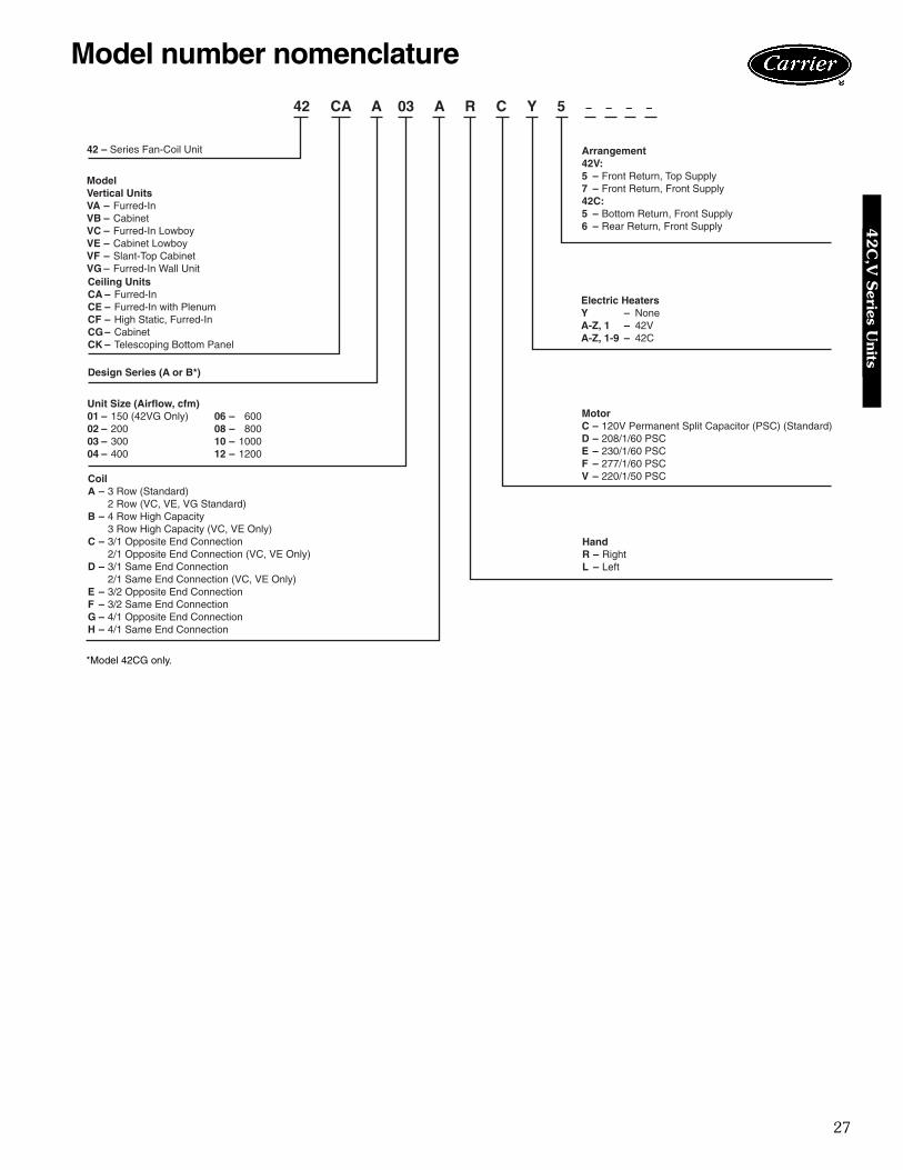
Model number nomenclature
42 – Series Fan-Coil Unit
CoilA – 3 Row (Standard)
2 Row (VC, VE, VG Standard)B – 4 Row High Capacity
3 Row High Capacity (VC, VE Only)C – 3/1 Opposite End Connection
2/1 Opposite End Connection (VC, VE Only)D – 3/1 Same End Connection
2/1 Same End Connection (VC, VE Only)E – 3/2 Opposite End ConnectionF – 3/2 Same End ConnectionG – 4/1 Opposite End ConnectionH – 4/1 Same End Connection
42 CA A 03 A R C Y 5 – – – –
ModelVertical UnitsVA – Furred-InVB – CabinetVC – Furred-In LowboyVE – Cabinet LowboyVF – Slant-Top CabinetVG – Furred-In Wall UnitCeiling UnitsCA – Furred-InCE – Furred-In with PlenumCF – High Static, Furred-InCG – CabinetCK – Telescoping Bottom Panel
Design Series (A or B*)
Unit Size (Airflow, cfm)01 – 150 (42VG Only) 06 – 60002 – 200 08 – 80003 – 300 10 – 100004 – 400 12 – 1200
HandR – RightL – Left
MotorC – 120V Permanent Split Capacitor (PSC) (Standard)D – 208/1/60 PSCE – 230/1/60 PSCF – 277/1/60 PSCV – 220/1/50 PSC
Electric HeatersY – NoneA-Z, 1 – 42VA-Z, 1-9 – 42C
Arrangement42V:5 – Front Return, Top Supply7 – Front Return, Front Supply42C:5 – Bottom Return, Front Supply6 – Rear Return, Front Supply
*Model 42CG only.
42C
,V S
eries Units

28
The 42C, V series fan coil units are certified in compliancewith the Air Conditioning and Refrigeration Institute (ARI)Industry Standard 440-98 for room fan coil units. Ap-proved standard ratings are tabulated below:
ARI APPROVED STANDARD RATINGS*
LEGEND
*Ratings based on motor at high fan speed, standard air and dry coil oper-ation, 10° F water temperature rise; entering-air temperature 67 F wb;80 F db; entering water temperature 45 F.
†Motor type permanent split capacitor operating at 115-1-60 voltage.**Shaded pole motor.
UNIT UNITSIZE
COILROWS
NOMINALCFM GPM
COOLING CAPACITYPOWER
INPUT (WATTS)†TotalMBtuh
SensibleMBtuh
42CA,CE,CG,CK
02
3
200 1.2 6.0 4.6 5003 300 1.8 9.0 6.9 8504 400 2.5 13.3 10.3 16506 600 3.6 18.0 14.6 22508 800 4.6 22.6 16.9 23510 1000 5.5 27.5 21.0 30512 1200 6.6 32.8 25.0 43502
4
200 1.4 6.9 5.0 5003 300 2.1 9.8 6.5 8504 400 2.8 13.8 9.8 14506 600 4.0 19.6 14.3 22008 800 5.1 25.5 18.8 23510 1000 6.2 31.0 23.0 30012 1200 7.5 37.2 27.7 425
42CF
04
4
400 3.2 16.0 11.6 17006 600 4.4 21.8 16.0 20508 800 5.3 26.5 19.6 22510 1000 7.5 37.2 27.6 355
42VA,VB,VF
02
3
200 1.0 4.8 3.5 5003 300 1.5 7.2 5.3 8004 400 2.4 11.2 7.9 13006 600 3.0 13.9 10.4 18008 800 4.0 19.1 13.5 21010 1000 4.8 22.0 16.8 24012 1200 5.3 26.3 20.0 37002
4
200 1.4 6.6 4.1 5003 300 2.0 9.9 7.0 8004 400 2.7 13.1 8.6 13006 600 3.8 18.6 13.6 17008 800 4.2 20.6 14.1 19510 1000 5.9 29.5 19.6 24012 1200 7.8 35.3 26.3 370
42VG 01 2 150 0.6 2.1 1.6 115**03 300 1.5 5.2 4.7 225**
42VC,VE
02
2
200 1.2 5.1 3.6 6803 300 2.0 8.6 6.7 13504 400 2.6 12.3 8.3 15006 600 3.6 18.3 13.2 26002
3
200 1.3 5.5 3.8 6803 300 2.4 10.9 7.1 13004 400 3.0 13.4 8.8 14506 600 4.1 21.1 14.6 250
GPM — Gallons per minuteMBtuh — Capacity (Btuh in thousands)
ARI capacity ratings42
C,V
Ser
ies
Uni
ts
29
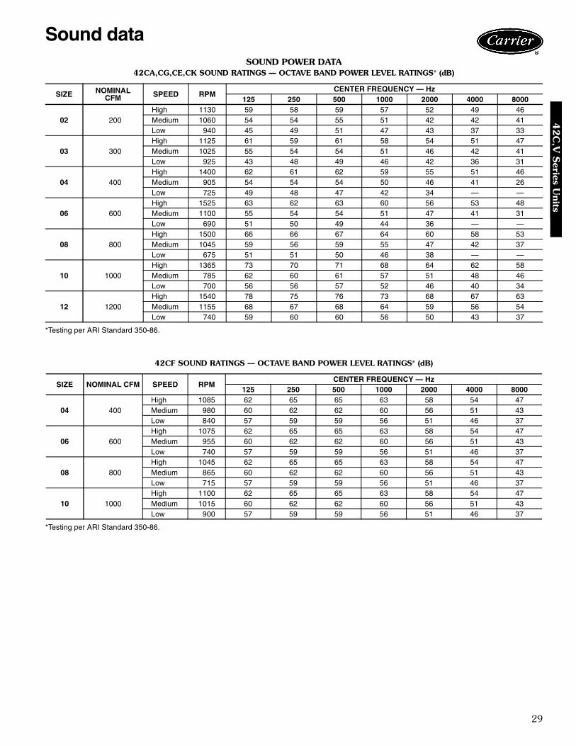
SOUND POWER DATA42CA,CG,CE,CK SOUND RATINGS — OCTAVE BAND POWER LEVEL RATINGS* (dB)
*Testing per ARI Standard 350-86.
42CF SOUND RATINGS — OCTAVE BAND POWER LEVEL RATINGS* (dB)
*Testing per ARI Standard 350-86.
SIZE NOMINALCFM SPEED RPM
CENTER FREQUENCY — Hz125 250 500 1000 2000 4000 8000
02 200High 1130 59 58 59 57 52 49 46Medium 1060 54 54 55 51 42 42 41Low 940 45 49 51 47 43 37 33
03 300High 1125 61 59 61 58 54 51 47Medium 1025 55 54 54 51 46 42 41Low 925 43 48 49 46 42 36 31
04 400High 1400 62 61 62 59 55 51 46Medium 905 54 54 54 50 46 41 26Low 725 49 48 47 42 34 — —
06 600High 1525 63 62 63 60 56 53 48Medium 1100 55 54 54 51 47 41 31Low 690 51 50 49 44 36 — —
08 800High 1500 66 66 67 64 60 58 53Medium 1045 59 56 59 55 47 42 37Low 675 51 51 50 46 38 — —
10 1000High 1365 73 70 71 68 64 62 58Medium 785 62 60 61 57 51 48 46Low 700 56 56 57 52 46 40 34
12 1200High 1540 78 75 76 73 68 67 63Medium 1155 68 67 68 64 59 56 54Low 740 59 60 60 56 50 43 37
SIZE NOMINAL CFM SPEED RPMCENTER FREQUENCY — Hz
125 250 500 1000 2000 4000 8000
04 400High 1085 62 65 65 63 58 54 47Medium 980 60 62 62 60 56 51 43Low 840 57 59 59 56 51 46 37
06 600High 1075 62 65 65 63 58 54 47Medium 955 60 62 62 60 56 51 43Low 740 57 59 59 56 51 46 37
08 800High 1045 62 65 65 63 58 54 47Medium 865 60 62 62 60 56 51 43Low 715 57 59 59 56 51 46 37
10 1000High 1100 62 65 65 63 58 54 47Medium 1015 60 62 62 60 56 51 43Low 900 57 59 59 56 51 46 37
Sound data4
2C
,V S
eries Units

30
SOUND POWER DATA42VA,VB,VF SOUND RATINGS — OCTAVE BAND SOUND POWER LEVEL RATINGS* (dB)
*Testing per ARI Standard 350-86.
42VC,VE SOUND RATINGS — OCTAVE BAND SOUND POWER LEVEL RATINGS* (dB)
*Testing per ARI Standard 350-86.
SIZE NOMINALCFM SPEED RPM
CENTER FREQUENCY — Hz125 250 500 1000 2000 4000 8000
02 200High 1130 63 58 53 46 40 34 25Medium 1090 58 57 51 45 39 32 —Low 1025 61 57 50 44 37 30 —
03 300High 1120 65 60 54 48 42 35 26Medium 1070 60 59 53 47 41 34 —Low 1000 63 59 52 46 39 32 —
04 400High 1520 66 67 64 58 50 45 39Medium 1085 58 60 53 47 40 32 —Low 840 52 55 47 40 33 — —
06 600High 1625 67 68 65 59 53 48 42Medium 1310 61 62 56 52 46 40 —Low 825 54 56 48 41 34 — —
08 800High 1610 68 68 65 60 55 51 44Medium 1300 63 64 59 54 50 45 36Low 820 55 56 49 43 37 28 —
10 1000High 1530 68 69 65 61 54 49 44Medium 1095 66 66 60 56 50 45 38Low 850 58 58 52 46 38 31 —
12 1200High 1625 70 71 67 63 56 51 46Medium 1310 69 69 63 59 53 48 42Low 830 60 61 54 48 41 34 —
SIZE NOMINALCFM SPEED RPM
CENTER FREQUENCY — Hz125 250 500 1000 2000 4000 8000
02 400High 1325 60 63 60 56 53 50 47Medium 890 53 53 51 46 43 38 32Low 655 50 48 43 38 33 — —
03 600High 1570 64 67 63 60 56 54 50Medium 1205 56 58 53 50 47 43 37Low 835 49 51 47 41 36 29 —
04 800High 1520 65 68 64 61 57 55 51Medium 1105 57 59 54 51 48 44 38Low 765 50 52 48 42 37 30 —
06 1000High 1575 66 67 63 61 56 53 50Medium 1205 58 58 55 53 48 43 37Low 835 51 50 47 44 38 30 —
Sound data (cont)42
C,V
Ser
ies
Uni
ts
31
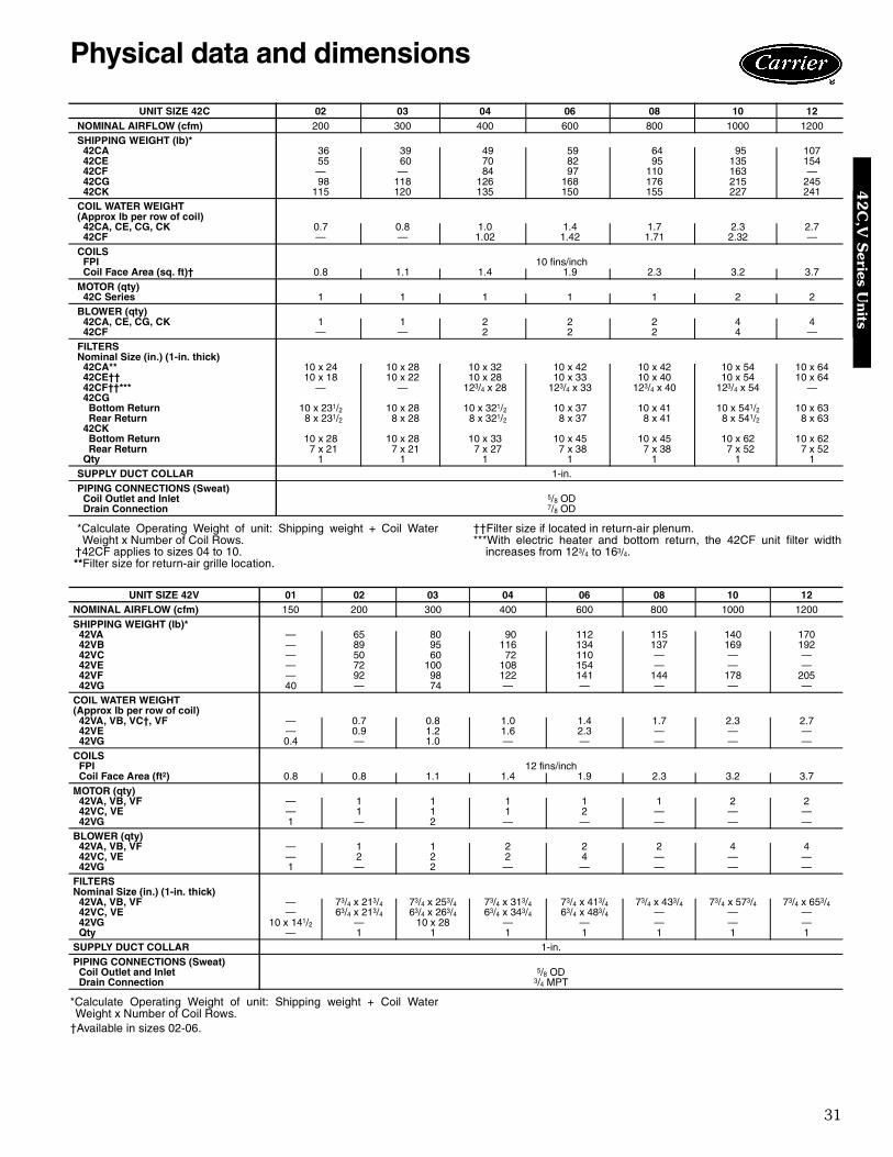
*Calculate Operating Weight of unit: Shipping weight + Coil WaterWeight x Number of Coil Rows.
†42CF applies to sizes 04 to 10.**Filter size for return-air grille location.
††Filter size if located in return-air plenum.***With electric heater and bottom return, the 42CF unit filter width
increases from 123/4 to 163/4.
*Calculate Operating Weight of unit: Shipping weight + Coil WaterWeight x Number of Coil Rows.
†Available in sizes 02-06.
UNIT SIZE 42C 02 03 04 06 08 10 12NOMINAL AIRFLOW (cfm) 200 300 400 600 800 1000 1200SHIPPING WEIGHT (lb)*
42CA 36 39 49 59 64 95 10742CE 55 60 70 82 95 135 15442CF — — 84 97 110 163 —42CG 98 118 126 168 176 215 24542CK 115 120 135 150 155 227 241
COIL WATER WEIGHT(Approx lb per row of coil)
42CA, CE, CG, CK 0.7 0.8 1.0 1.4 1.7 2.3 2.742CF — — 1.02 1.42 1.71 2.32 —
COILSFPI 10 fins/inchCoil Face Area (sq. ft)† 0.8 1.1 1.4 1.9 2.3 3.2 3.7
MOTOR (qty)42C Series 1 1 1 1 1 2 2
BLOWER (qty)42CA, CE, CG, CK 1 1 2 2 2 4 442CF — — 2 2 2 4 —
FILTERSNominal Size (in.) (1-in. thick)
42CA** 10 x 24 10 x 28 10 x 32 10 x 42 10 x 42 10 x 54 10 x 6442CE†† 10 x 18 10 x 22 10 x 28 10 x 33 10 x 40 10 x 54 10 x 6442CF††*** — — 123/4 x 28 123/4 x 33 123/4 x 40 123/4 x 54 —42CGBottom Return 10 x 231/2 10 x 28 10 x 321/2 10 x 37 10 x 41 10 x 541/2 10 x 63Rear Return 8 x 231/2 8 x 28 8 x 321/2 8 x 37 8 x 41 8 x 541/2 8 x 63
42CKBottom Return 10 x 28 10 x 28 10 x 33 10 x 45 10 x 45 10 x 62 10 x 62Rear Return 7 x 21 7 x 21 7 x 27 7 x 38 7 x 38 7 x 52 7 x 52
Qty 1 1 1 1 1 1 1SUPPLY DUCT COLLAR 1-in.
PIPING CONNECTIONS (Sweat)Coil Outlet and Inlet 5/8 ODDrain Connection 7/8 OD
UNIT SIZE 42V 01 02 03 04 06 08 10 12NOMINAL AIRFLOW (cfm) 150 200 300 400 600 800 1000 1200
SHIPPING WEIGHT (lb)*42VA — 65 80 90 112 115 140 17042VB — 89 95 116 134 137 169 19242VC — 50 60 72 110 — — —42VE — 72 100 108 154 — — —42VF — 92 98 122 141 144 178 20542VG 40 — 74 — — — — —
COIL WATER WEIGHT(Approx lb per row of coil)
42VA, VB, VC†, VF — 0.7 0.8 1.0 1.4 1.7 2.3 2.742VE — 0.9 1.2 1.6 2.3 — — —42VG 0.4 — 1.0 — — — — —
COILSFPI 12 fins/inchCoil Face Area (ft2) 0.8 0.8 1.1 1.4 1.9 2.3 3.2 3.7
MOTOR (qty)42VA, VB, VF — 1 1 1 1 1 2 242VC, VE — 1 1 1 2 — — —42VG 1 — 2 — — — — —
BLOWER (qty)42VA, VB, VF — 1 1 2 2 2 4 442VC, VE — 2 2 2 4 — — —42VG 1 — 2 — — — — —
FILTERSNominal Size (in.) (1-in. thick)
42VA, VB, VF — 73/4 x 213/4 73/4 x 253/4 73/4 x 313/4 73/4 x 413/4 73/4 x 433/4 73/4 x 573/4 73/4 x 653/442VC, VE — 63/4 x 213/4 63/4 x 263/4 63/4 x 343/4 63/4 x 483/4 — — —42VG 10 x 141/2 — 10 x 28 — — — — —Qty — 1 1 1 1 1 1 1
SUPPLY DUCT COLLAR 1-in.
PIPING CONNECTIONS (Sweat)Coil Outlet and Inlet 5/8 ODDrain Connection 3/4 MPT
Physical data and dimensions4
2C
,V S
eries Units
32
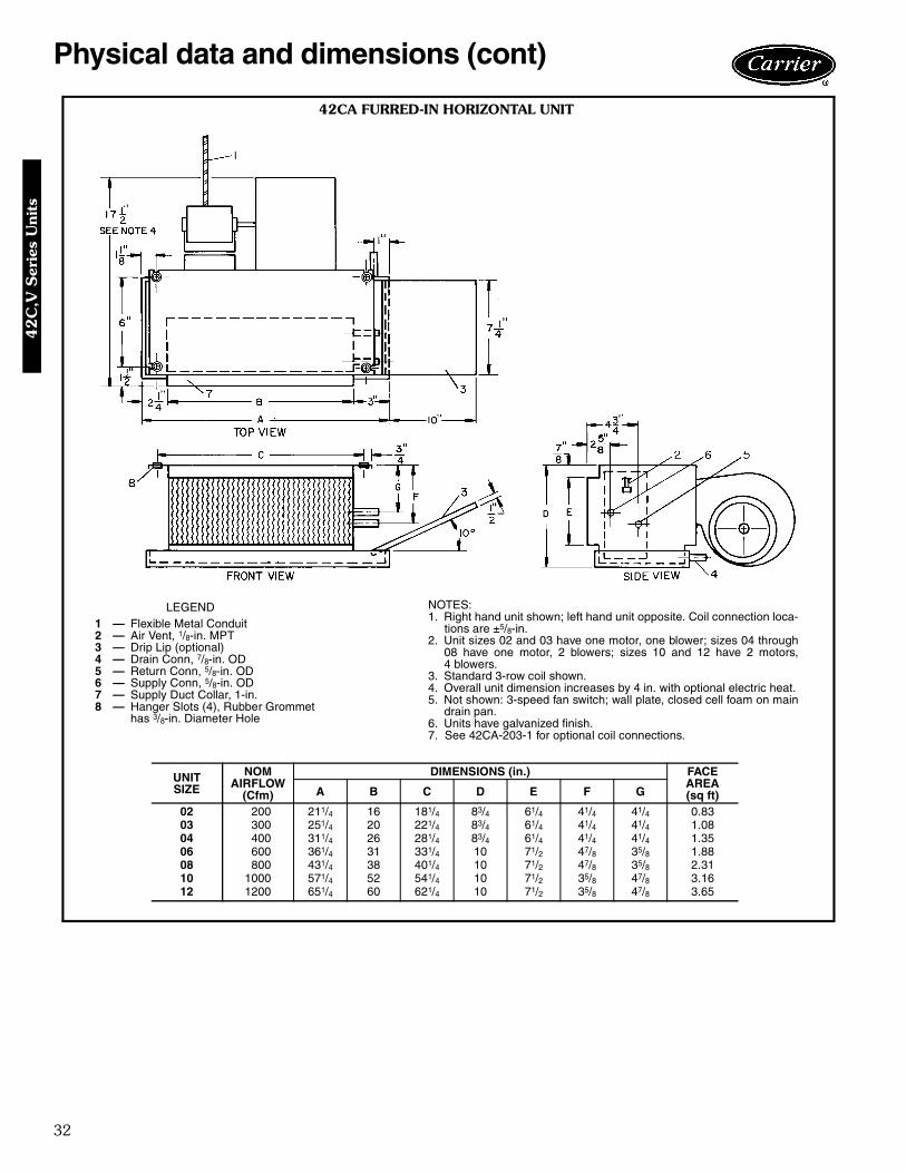
Physical data and dimensions (cont)
42CA FURRED-IN HORIZONTAL UNIT
LEGEND1 — Flexible Metal Conduit2 — Air Vent, 1/8-in. MPT3 — Drip Lip (optional)4 — Drain Conn, 7/8-in. OD5 — Return Conn, 5/8-in. OD6 — Supply Conn, 5/8-in. OD7 — Supply Duct Collar, 1-in.8 — Hanger Slots (4), Rubber Grommet
has 3/8-in. Diameter Hole
UNITSIZE
NOMAIRFLOW
(Cfm)
DIMENSIONS (in.) FACEAREA(sq ft)A B C D E F G
02 200 211/4 16 181/4 83/4 61/4 41/4 41/4 0.8303 300 251/4 20 221/4 83/4 61/4 41/4 41/4 1.0804 400 311/4 26 281/4 83/4 61/4 41/4 41/4 1.3506 600 361/4 31 331/4 10 71/2 47/8 35/8 1.8808 800 431/4 38 401/4 10 71/2 47/8 35/8 2.3110 1000 571/4 52 541/4 10 71/2 35/8 47/8 3.1612 1200 651/4 60 621/4 10 71/2 35/8 47/8 3.65
NOTES:1. Right hand unit shown; left hand unit opposite. Coil connection loca-
tions are ±5/8-in.2. Unit sizes 02 and 03 have one motor, one blower; sizes 04 through
08 have one motor, 2 blowers; sizes 10 and 12 have 2 motors,4 blowers.
3. Standard 3-row coil shown.4. Overall unit dimension increases by 4 in. with optional electric heat.5. Not shown: 3-speed fan switch; wall plate, closed cell foam on main
drain pan.6. Units have galvanized finish.7. See 42CA-203-1 for optional coil connections.
42
C,V
Ser
ies
Uni
ts

33
42CE FURRED-IN HORIZONTAL UNIT WITH PLENUM
UNITSIZE
NOMAIRFLOW
(Cfm)
DIMENSIONS (in.) FACEAREA(sq ft)A B C D E F G H
02 200 211/4 16 181/4 61/4 83/4 181/4 41/4 41/4 0.8303 300 251/4 20 221/4 61/4 83/4 221/4 41/4 41/4 1.0804 400 311/4 26 281/4 61/4 83/4 281/4 41/4 41/4 1.3506 600 361/4 31 331/4 71/2 10 331/4 47/8 35/8 1.8808 800 431/4 38 401/4 71/2 10 401/4 47/8 35/8 2.3110 1000 571/4 52 541/4 71/2 10 541/4 35/8 47/8 3.1612 1200 651/4 60 621/4 71/2 10 621/4 35/8 47/8 3.65
NOTES:1. Right hand unit with standard 3-row coil shown; left hand unit opposite. Coil
connection locations are ±5/8-in.2. Unit sizes 02 and 03 have one motor, one blower; sizes 04 through 08 have
one motor, 2 blowers; sizes 10 and 12 have 2 motors, 4 blowers.3. Standard 3-row coil shown.4. Unit available with bottom or rear return air.5. Dimension increases by 4 in. with optional electric heat.6. Not shown: 3-speed fan switch; wall plate, 1/2-in. fiberglass insulation on
inside of plenum, closed cell foam on main drain pan.7. Units have galvanized finish.8. See 42CA-203-1 for optional coil connections.
LEGEND1 — Flexible Metal Conduit2 — Junction Box, 4 in. x 4 in.3 — Air Vent, 1/8-in. MPT4 — Drip Lip (optional, shipped loose)5 — Drain Conn, 7/8-in. OD6 — Return Conn, 5/8-in. OD7 — Supply Conn, 5/8-in. OD8 — Supply Duct Collar, 1-in.9 — Hanger Slots (4), Rubber Grommet has
3/8-in. Diameter Hole10 — Filter11 — Access Panel12 — Mounting Bracket
42C
,V S
eries Units
34
Physical data and dimensions (cont)
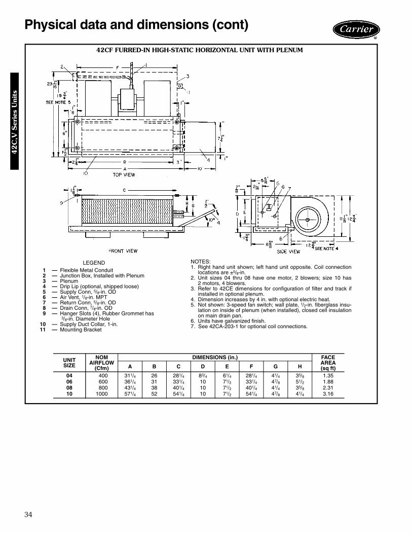
42CF FURRED-IN HIGH-STATIC HORIZONTAL UNIT WITH PLENUM
LEGEND1 — Flexible Metal Conduit2 — Junction Box, Installed with Plenum3 — Plenum4 — Drip Lip (optional, shipped loose)5 — Supply Conn, 5/8-in. OD6 — Air Vent, 1/8-in. MPT7 — Return Conn, 5/8-in. OD8 — Drain Conn, 7/8-in. OD9 — Hanger Slots (4), Rubber Grommet has
3/8-in. Diameter Hole10 — Supply Duct Collar, 1-in.11 — Mounting Bracket
UNITSIZE
NOMAIRFLOW
(Cfm)
DIMENSIONS (in.) FACEAREA(sq ft)A B C D E F G H
04 400 311/4 26 281/4 83/4 61/4 281/4 41/4 35/8 1.3506 600 361/4 31 331/4 10 71/2 331/4 47/8 51/2 1.8808 800 431/4 38 401/4 10 71/2 401/4 41/4 35/8 2.3110 1000 571/4 52 541/4 10 71/2 541/4 47/8 41/4 3.16
NOTES:1. Right hand unit shown; left hand unit opposite. Coil connection
locations are ±5/8-in.2. Unit sizes 04 thru 08 have one motor, 2 blowers; size 10 has
2 motors, 4 blowers.3. Refer to 42CE dimensions for configuration of filter and track if
installed in optional plenum.4. Dimension increases by 4 in. with optional electric heat.5. Not shown: 3-speed fan switch; wall plate, 1/2-in. fiberglass insu-
lation on inside of plenum (when installed), closed cell insulationon main drain pan.
6. Units have galvanized finish.7. See 42CA-203-1 for optional coil connections.
42
C,V
Ser
ies
Uni
ts
35
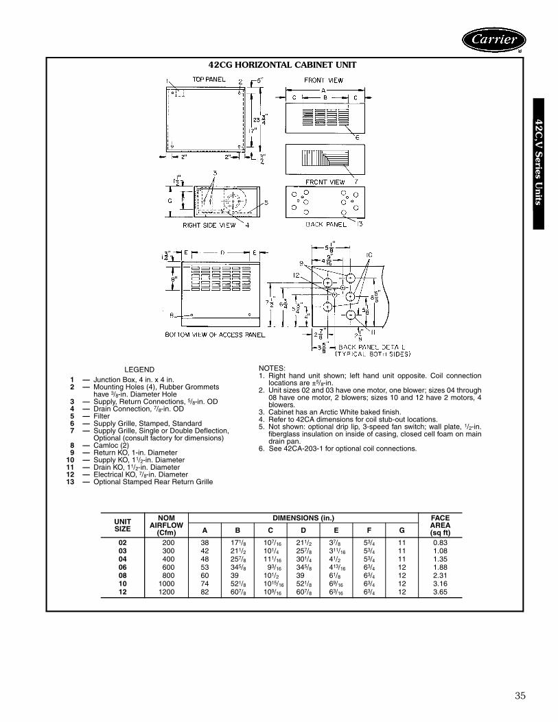
42CG HORIZONTAL CABINET UNIT
LEGEND1 — Junction Box, 4 in. x 4 in.2 — Mounting Holes (4), Rubber Grommets
have 3/8-in. Diameter Hole3 — Supply, Return Connections, 5/8-in. OD4 — Drain Connection, 7/8-in. OD5 — Filter6 — Supply Grille, Stamped, Standard7 — Supply Grille, Single or Double Deflection,
Optional (consult factory for dimensions)8 — Camloc (2)9 — Return KO, 1-in. Diameter
10 — Supply KO, 11/2-in. Diameter11 — Drain KO, 11/2-in. Diameter12 — Electrical KO, 7/8-in. Diameter13 — Optional Stamped Rear Return Grille
UNITSIZE
NOMAIRFLOW
(Cfm)
DIMENSIONS (in.) FACEAREA(sq ft)A B C D E F G
02 200 38 171/8 107/16 211/2 37/8 53/4 11 0.8303 300 42 211/2 101/4 257/8 311/16 53/4 11 1.0804 400 48 257/8 111/16 301/4 41/2 53/4 11 1.3506 600 53 345/8 93/16 345/8 413/16 63/4 12 1.8808 800 60 39 101/2 39 61/8 63/4 12 2.3110 1000 74 521/8 1015/16 521/8 69/16 63/4 12 3.1612 1200 82 607/8 109/16 607/8 63/16 63/4 12 3.65
NOTES:1. Right hand unit shown; left hand unit opposite. Coil connection
locations are ±5/8-in.2. Unit sizes 02 and 03 have one motor, one blower; sizes 04 through
08 have one motor, 2 blowers; sizes 10 and 12 have 2 motors, 4blowers.
3. Cabinet has an Arctic White baked finish.4. Refer to 42CA dimensions for coil stub-out locations.5. Not shown: optional drip lip, 3-speed fan switch; wall plate, 1/2-in.
fiberglass insulation on inside of casing, closed cell foam on maindrain pan.
6. See 42CA-203-1 for optional coil connections.
42C
,V S
eries Units
36
Physical data and dimensions (cont)
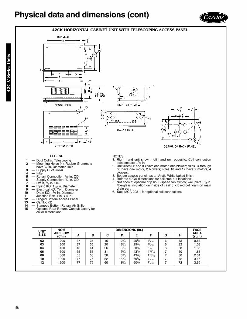
42CK HORIZONTAL CABINET UNIT WITH TELESCOPING ACCESS PANEL
LEGEND1 — Duct Collar, Telescoping2 — Mounting Holes (4), Rubber Grommets
have 3/8-in. Diameter Hole3 — Supply Duct Collar4 — Filter5 — Return Connection, 5/8-in. OD.6 — Supply Connection, 5/8-in. OD.7 — Drain, 7/8-in. OD.8 — Piping KO, 11/2-in. Diameter9 — Electrical KO, 7/8-in. Diameter
10 — Drain KO, 11/2-in. Diameter11 — Junction Box, 4 in. x 4 in.12 — Hinged Bottom Access Panel13 — Camloc (2)14 — Stamped Bottom Return Air Grille15 — Optional Rear Return. Consult factory for
collar dimensions.
UNITSIZE
NOMAIRFLOW
(Cfm)
DIMENSIONS (in.) FACEAREA(sq ft)A B C D E F G H
02 200 37 35 16 123/4 257/8 49/16 6 32 0.8303 300 37 35 20 83/4 257/8 49/16 6 32 1.0804 400 43 41 26 83/4 301/4 53/8 6 38 1.3506 600 55 53 31 153/4 433/8 413/16 7 50 1.8808 800 55 53 38 83/4 433/8 413/16 7 50 2.3110 1000 77 75 52 163/4 607/8 71/16 7 72 3.1612 1200 77 75 60 83/4 607/8 71/16 7 72 3.65
NOTES:1. Right hand unit shown; left hand unit opposite. Coil connection
locations are ±5/8-in.2. Unit sizes 02 and 03 have one motor, one blower; sizes 04 through
08 have one motor, 2 blowers; sizes 10 and 12 have 2 motors, 4blowers.
3. Bottom access panel has an Arctic White baked finish.4. Refer to 42CA dimensions for coil stub-out locations.5. Not shown: optional drip lip, 3-speed fan switch; wall plate, 1/2-in.
fiberglass insulation on inside of casing, closed cell foam on maindrain pan.
6. See 42CA-203-1 for optional coil connections.
42
C,V
Ser
ies
Uni
ts
37
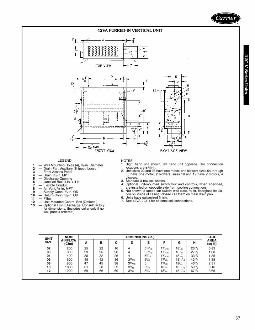
42VA FURRED-IN VERTICAL UNIT
LEGEND1 — Wall Mounting Holes (4), 3/4-in. Diameter2 — Drain Pan, Auxiliary, Shipped Loose3 — Front Access Panel4 — Drain, 3/4-in. MPT5 — Discharge Opening6 — Junction Box, 4 in. x 4 in.7 — Flexible Conduit8 — Air Vent, 1/8-in. MPT9 — Supply Conn, 5/8-in. OD
10 — Return Conn, 5/8-in. OD11 — Filter12 — Unit-Mounted Control Box (Optional)13 — Optional Front Discharge. Consult factory
for dimensions. (Includes collar only if nowall panels ordered.)
UNITSIZE
NOMAIRFLOW
(Cfm)
DIMENSIONS (in.) FACEAREA(sq ft)A B C D E F G H
02 200 25 22 16 4 515/16 171/16 181/8 231/2 0.8303 300 29 26 20 4 515/16 171/16 181/8 271/2 1.0804 400 35 32 26 4 55/16 171/16 181/8 331/2 1.3506 600 45 42 36 311/16 55/8 175/8 1811/16 431/2 1.8808 800 47 45 38 311/16 5 175/8 193/4 461/2 2.3110 1000 61 58 52 31/16 55/8 183/4 1811/16 591/2 3.1612 1200 69 66 60 31/16 55/8 183/4 1811/16 671/2 3.65
NOTES:1. Right hand unit shown; left hand unit opposite. Coil connection
locations are ± 5/8-in.2. Unit sizes 02 and 03 have one motor, one blower; sizes 04 through
08 have one motor, 2 blowers; sizes 10 and 12 have 2 motors, 4blowers.
3. Standard 3-row coil shown.4. Optional unit-mounted switch box and controls, when specified,
are installed on opposite side from cooling connections.5. Not shown: 3-speed fan switch; wall plate, 1/2-in. fiberglass insula-
tion on inside of casing, closed cell foam on main drain pan.6. Units have galvanized finish.7. See 42VA-203-1 for optional coil connections.
42C
,V S
eries Units
38
Physical data and dimensions (cont)
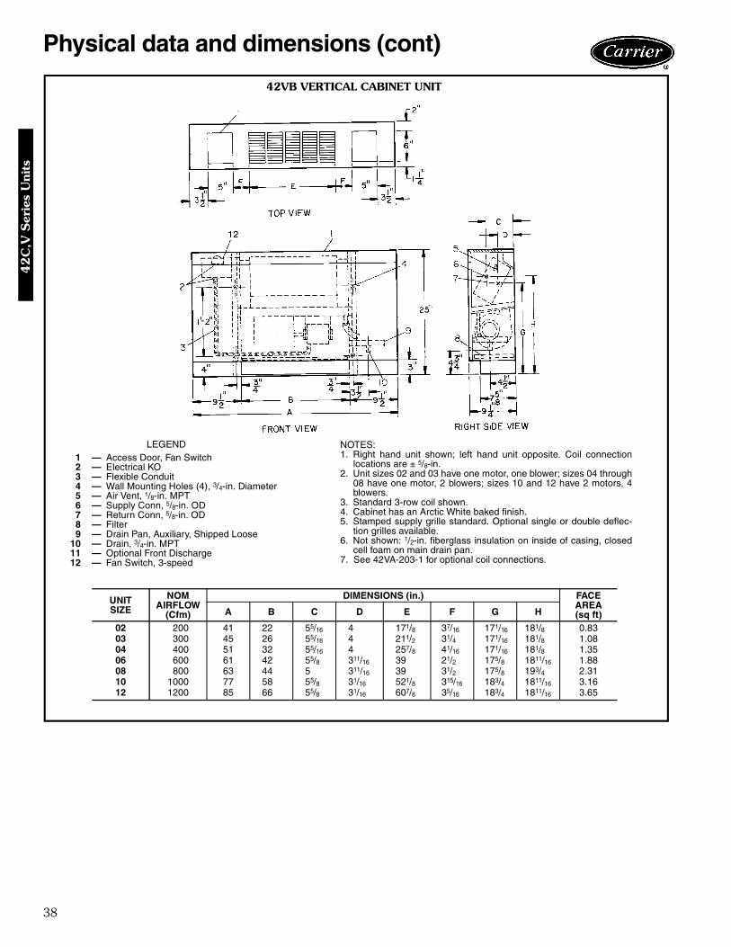
42VB VERTICAL CABINET UNIT
LEGEND1 — Access Door, Fan Switch2 — Electrical KO3 — Flexible Conduit4 — Wall Mounting Holes (4), 3/4-in. Diameter5 — Air Vent, 1/8-in. MPT6 — Supply Conn, 5/8-in. OD7 — Return Conn, 5/8-in. OD8 — Filter9 — Drain Pan, Auxiliary, Shipped Loose
10 — Drain, 3/4-in. MPT11 — Optional Front Discharge12 — Fan Switch, 3-speed
NOTES:1. Right hand unit shown; left hand unit opposite. Coil connection
locations are ± 5/8-in.2. Unit sizes 02 and 03 have one motor, one blower; sizes 04 through
08 have one motor, 2 blowers; sizes 10 and 12 have 2 motors, 4blowers.
3. Standard 3-row coil shown.4. Cabinet has an Arctic White baked finish.5. Stamped supply grille standard. Optional single or double deflec-
tion grilles available.6. Not shown: 1/2-in. fiberglass insulation on inside of casing, closed
cell foam on main drain pan.7. See 42VA-203-1 for optional coil connections.
UNITSIZE
NOMAIRFLOW
(Cfm)
DIMENSIONS (in.) FACEAREA(sq ft)A B C D E F G H
02 200 41 22 55/16 4 171/8 37/16 171/16 181/8 0.8303 300 45 26 55/16 4 211/2 31/4 171/16 181/8 1.0804 400 51 32 55/16 4 257/8 41/16 171/16 181/8 1.3506 600 61 42 55/8 311/16 39 21/2 175/8 1811/16 1.8808 800 63 44 5 311/16 39 31/2 175/8 193/4 2.3110 1000 77 58 55/8 31/16 521/8 315/16 183/4 1811/16 3.1612 1200 85 66 55/8 31/16 607/8 35/16 183/4 1811/16 3.65
42
C,V
Ser
ies
Uni
ts
39
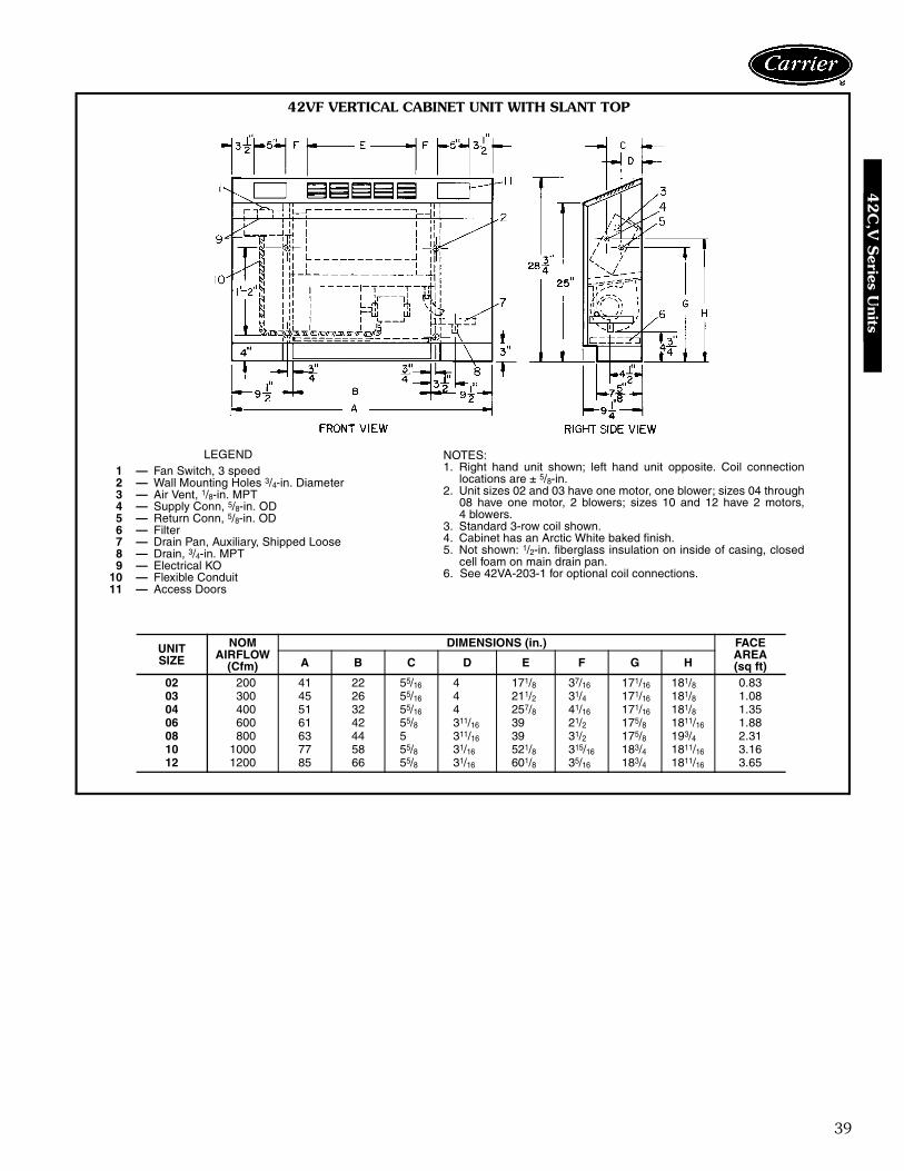
42VF VERTICAL CABINET UNIT WITH SLANT TOP
LEGEND1 — Fan Switch, 3 speed2 — Wall Mounting Holes 3/4-in. Diameter3 — Air Vent, 1/8-in. MPT4 — Supply Conn, 5/8-in. OD5 — Return Conn, 5/8-in. OD6 — Filter7 — Drain Pan, Auxiliary, Shipped Loose8 — Drain, 3/4-in. MPT9 — Electrical KO
10 — Flexible Conduit11 — Access Doors
NOTES:1. Right hand unit shown; left hand unit opposite. Coil connection
locations are ± 5/8-in.2. Unit sizes 02 and 03 have one motor, one blower; sizes 04 through
08 have one motor, 2 blowers; sizes 10 and 12 have 2 motors,4 blowers.
3. Standard 3-row coil shown.4. Cabinet has an Arctic White baked finish.5. Not shown: 1/2-in. fiberglass insulation on inside of casing, closed
cell foam on main drain pan.6. See 42VA-203-1 for optional coil connections.
UNITSIZE
NOMAIRFLOW
(Cfm)
DIMENSIONS (in.) FACEAREA(sq ft)A B C D E F G H
02 200 41 22 55/16 4 171/8 37/16 171/16 181/8 0.8303 300 45 26 55/16 4 211/2 31/4 171/16 181/8 1.0804 400 51 32 55/16 4 257/8 41/16 171/16 181/8 1.3506 600 61 42 55/8 311/16 39 21/2 175/8 1811/16 1.8808 800 63 44 5 311/16 39 31/2 175/8 193/4 2.3110 1000 77 58 55/8 31/16 521/8 315/16 183/4 1811/16 3.1612 1200 85 66 55/8 31/16 601/8 35/16 183/4 1811/16 3.65
42C
,V S
eries Units

40
Physical data and dimensions (cont)
42VC FURRED-IN LOBOY UNIT
LEGEND1 — Discharge Opening2 — Junction Box, 4 in. x 4 in.3 — Return Conn, 5/8-in. OD4 — Air Vent, 1/8-in. MPT5 — Supply Conn, 5/8-in. OD6 — Drain Pan, Auxiliary, Shipped Loose7 — Drain, 3/4-in. MPT8 — Filter9 — Unit-Mounted Control Box (Optional)
UNITSIZE
NOMAIRFLOW
(Cfm)
DIMENSIONS (in.) FACEAREA(sq ft)A B C D E F G
02 200 23 22 17 111/4 107/16 1 103/8 1.1803 300 28 27 22 111/4 107/16 1 103/8 1.5304 400 36 35 30 111/4 107/16 1 103/8 2.0806 600 50 49 44 113/4 10 11/4 10 3.06
NOTES:1. Right hand unit shown; left hand unit opposite. Coil connection
locations are ± 5/8-in.2. Unit sizes 02 through 04 have one motor, 2 blowers; size 06 has
2 motors, 4 blowers.3. Standard 2-row coil shown.4. Optional unit-mounted switch box and controls, when specified,
are installed on opposite side from cooling connections.5. Height increases by 2 in. with electric heat.6. Not shown: 3-speed fan switch, 1/2-in. fiberglass insulation on
inside of casing, closed cell foam on main drain pan.7. Units have galvanized finish.8. See 42VC-203-1 for optional coil connections.
42
C,V
Ser
ies
Uni
ts

41
42VE CABINET LOBOY UNIT
LEGEND1 — Fan Switch, 3-Speed, behind Access Door2 — Stamped Supply Grille3 — Electrical KO4 — Return Conn, 5/8-in. OD5 — Air Vent, 1/8-in. MPT6 — Supply Conn, 5/8-in. OD7 — Drain Pan, Auxiliary, with 3/4-in. MPT
Drain Connection8 — Filter9 — Return Air Grille
UNITSIZE
NOMAIRFLOW
(Cfm)
DIMENSIONS (in.) FACEAREA(sq ft)A B C D E F G H
02 200 41 22 171/8 37/16 111/4 107/16 1 103/8 1.1803 300 46 27 211/2 33/4 111/4 107/16 1 103/8 1.5304 400 54 35 301/4 33/8 111/4 107/16 1 103/8 2.0806 600 68 49 433/8 313/16 113/4 10 11/4 103/8 3.06
NOTES:1. Right hand unit shown; left hand unit opposite. Coil connection
locations are ± 5/8-in.2. Unit sizes 02 through 04 have one motor, 2 blowers; size 06 has
2 motors, 4 blowers.3. Cabinet has an Arctic White baked finish.4. Height increases by 2 in. with electric heat.5. Standard 2-row coil shown.6. Not shown: 1/2-in. fiberglass insulation on inside of casing, closed
cell foam on main drain pan.8. See 42VC-203-1 for optional coil connections.
42C
,V S
eries Units

42
Physical data and dimensions (cont)
42VG FURRED-IN WALL UNIT
LEGEND1 — Electrical KO, 7/8-in. Diameter2 — Stamped Supply Grille3 — Return Conn, 5/8-in. OD4 — Supply Conn, 5/8-in. OD5 — Air Vent, 1/8-in. MPT6 — Opening for Drain Conn, 1-in. Diameter7 — Drain Conn, 7/8-in. OD8 — Filter9 — Return Air Grille, Stamped
10 — Junction Box11 — Front Panel
NOTES:1. Right hand unit shown; left hand unit opposite. Coil connection
locations are ± 5/8-in.2. Front panel has an Arctic White baked finish.3. Standard 2-row coil shown.4. Unit size 01 has one motor, one blower; size 03 has 2 motors,
2 blowers.5. Unit has 1/2-in. flanges for mounting to wall surface.6. Front panel hooks at top of unit, swing down and snap in at bottom
against a spring clip.7. Not shown: 3-speed fan switch, wall plate, 1/2-in. fiberglass insula-
tion on inside of casing, closed cell foam on main drain pan.
UNITSIZE
NOMAIRFLOW
(Cfm)
DIMENSIONS (in.)
A B C D E
01 150 253/4 14 11/2 123/4 1003 300 393/4 28 115/16 257/8 24
42
C,V
Ser
ies
Uni
ts

43
Accessory dimensions
OUTSIDE AIR OPENING/DAMPER
UNITSIZE
NOMINALAIRFLOW
(CFM)
DIM. A(in.)
02 200 803 300 1004 400 1206 600 1408 800 1810 1000 2712 1200 27
NOTE: A 6-in. diameter outside air opening with duct collar and filter is available for42CE,CF,CG,CK,VA,VB, and VF units. It is also available with a round damper.
42C
,V S
eries Units

44
Accessory dimensions (cont)42C
OPTIO
NA
L C
OIL
CO
NN
EC
TIO
N L
OC
ATIO
N S
IZE 0
2 T
HR
U 1
2N
OT
ES
:1.
Rig
htha
ndun
itsh
own;
left
hand
unit
oppo
site
.2.
All
dim
ensi
ons
are
inin
ches
±1 /
4in
ch.
3.D
imen
sion
sdo
nota
pply
toun
itsw
ithfa
ctor
yva
lve
pack
ages
.4.
All
conn
ectio
nsi
zes
5 /8″
O.D
.
CO
ILC
ON
NE
CT
ION
DIM
EN
SIO
NS
R I G H T H A N D
UN
ITS
IZE
3-R
OW
CO
IL4-
RO
WC
OIL
3A
ND
1S
PL
ITC
OIL
AB
CD
EF
GH
JK
LM
NP
Q02
43/ 4
25/ 8
41/ 4
41/ 4
35/ 8
41/ 4
55/ 1
621
/ 16
55/ 1
631
/ 841
/ 455
/ 811
/ 821
/ 16
41/ 4
0343
/ 425
/ 841
/ 441
/ 435
/ 841
/ 455
/ 16
21/ 1
655
/ 16
31/ 8
41/ 4
55/ 8
11/ 8
21/ 1
641
/ 404
43/ 4
25/ 8
41/ 4
41/ 4
35/ 8
41/ 4
55/ 1
621
/ 16
55/ 1
631
/ 841
/ 455
/ 811
/ 821
/ 16
41/ 4
0643
/ 425
/ 835
/ 847
/ 851
/ 247
/ 855
/ 16
21/ 1
655
/ 16
31/ 8
47/ 8
67/ 8
23/ 8
21/ 1
647
/ 808
43/ 4
25/ 8
35/ 8
47/ 8
35/ 8
41/ 4
55/ 1
621
/ 16
55/ 1
631
/ 847
/ 867
/ 823
/ 821
/ 16
47/ 8
1043
/ 425
/ 847
/ 835
/ 841
/ 447
/ 855
/ 16
21/ 1
655
/ 16
31/ 8
51/ 2
67/ 8
23/ 8
21/ 1
641
/ 412
43/ 4
25/ 8
47/ 8
35/ 8
41/ 4
47/ 8
55/ 1
621
/ 16
55/ 1
631
/ 851
/ 267
/ 823
/ 821
/ 16
41/ 4
R I G H T H A N D
UN
ITS
IZE
3A
ND
2S
PL
ITC
OIL
R I G H T H A N D
UN
ITS
IZE
4A
ND
1S
PL
ITC
OIL
JK
LM
NP
QJ
KL
MN
PQ
0265
/ 16
41/ 8
41/ 4
55/ 8
13/ 4
211 /
1641
/ 402
53/ 1
625
/ 841
/ 455
/ 811
/ 819
/ 16
41/ 4
0365
/ 16
41/ 8
41/ 4
55/ 8
13/ 4
211 /
1641
/ 403
55/ 1
625
/ 841
/ 455
/ 811
/ 819
/ 16
41/ 4
0465
/ 16
41/ 8
41/ 4
55/ 8
13/ 4
211 /
1641
/ 404
55/ 1
625
/ 841
/ 455
/ 811
/ 819
/ 16
41/ 4
0665
/ 16
41/ 8
47/ 8
67/ 8
321
1 /16
47/ 8
0655
/ 16
25/ 8
47/ 8
67/ 8
23/ 8
19/ 1
647
/ 808
65/ 1
641
/ 847
/ 867
/ 83
211 /
1647
/ 808
55/ 1
625
/ 847
/ 867
/ 823
/ 819
/ 16
47/ 8
1065
/ 16
41/ 8
51/ 2
67/ 8
321
1 /16
41/ 4
1055
/ 16
25/ 8
51/ 2
67/ 8
23/ 8
19/ 1
641
/ 412
65/ 1
641
/ 851
/ 267
/ 83
211 /
1647
/ 812
55/ 1
625
/ 851
/ 267
/ 823
/ 819
/ 16
41/ 4
L E F T H A N D
UN
ITS
IZE
3-R
OW
CO
IL4-
RO
WC
OIL
3A
ND
1S
PL
ITC
OIL
AB
CD
EF
GH
JK
LM
NP
Q02
43/ 4
25/ 8
41/ 4
41/ 4
41/ 4
35/ 8
55/ 1
621
/ 16
55/ 1
631
/ 835
/ 85
1 /2
21/ 1
635
/ 803
43/ 4
25/ 8
41/ 4
41/ 4
41/ 4
35/ 8
55/ 1
621
/ 16
55/ 1
631
/ 835
/ 85
1 /2
21/ 1
635
/ 804
43/ 4
25/ 8
41/ 4
41/ 4
41/ 4
35/ 8
55/ 1
621
/ 16
55/ 1
631
/ 835
/ 85
1 /2
21/ 1
635
/ 806
43/ 4
25/ 8
47/ 8
35/ 8
47/ 8
51/ 2
55/ 1
621
/ 16
55/ 1
631
/ 841
/ 463
/ 41 /
221
/ 16
41/ 4
0843
/ 425
/ 847
/ 835
/ 841
/ 435
/ 855
/ 16
21/ 1
655
/ 16
31/ 8
41/ 4
63/ 4
1 /2
21/ 1
641
/ 410
43/ 4
25/ 8
35/ 8
47/ 8
47/ 8
41/ 2
55/ 1
621
/ 16
55/ 1
631
/ 835
/ 863
/ 41 /
221
/ 16
47/ 8
1243
/ 425
/ 835
/ 847
/ 847
/ 841
/ 255
/ 16
21/ 1
655
/ 16
31/ 8
35/ 8
63/ 4
1 /2
21/ 1
647
/ 8
L E F T H A N D
UN
ITS
IZE
3A
ND
2S
PL
ITC
OIL
JK
LM
NP
Q02
65/ 1
641
/ 835
/ 85
11/ 8
211 /
1635
/ 803
65/ 1
641
/ 835
/ 85
11/ 8
211 /
1635
/ 804
65/ 1
641
/ 835
/ 85
11/ 8
211 /
1635
/ 806
65/ 1
641
/ 841
/ 463
/ 411
/ 821
1 /16
41/ 4
0865
/ 16
41/ 8
41/ 4
63/ 4
11/ 8
211 /
1641
/ 410
65/ 1
641
/ 835
/ 863
/ 411
/ 821
1 /16
47/ 8
1265
/ 16
41/ 8
35/ 8
63/ 4
11/ 8
211 /
1647
/ 8
L E F T H A N D
UN
ITS
IZE
4A
ND
1S
PL
ITC
OIL
JK
LM
NP
Q02
53/ 1
625
/ 835
/ 85
1 /2
19/ 1
635
/ 803
55/ 1
625
/ 835
/ 85
1 /2
19/ 1
635
/ 804
55/ 1
625
/ 835
/ 85
1 /2
19/ 1
635
/ 806
55/ 1
625
/ 841
/ 463
/ 41 /
219
/ 16
41/ 4
0855
/ 16
25/ 8
41/ 4
63/ 4
1 /2
19/ 1
641
/ 410
55/ 1
625
/ 835
/ 863
/ 41 /
219
/ 16
47/ 8
1255
/ 16
25/ 8
35/ 8
63/ 4
1 /2
19/ 1
647
/ 8
42
C,V
Ser
ies
Uni
ts

45
42VA
,VB
,VF
OPTIO
NA
L C
OIL
CO
NN
EC
TIO
N L
OC
ATIO
N S
IZE 0
2 T
HR
U 1
2
NO
TE
S:
1.D
imen
sion
sfo
rsp
litco
ilsw
ithop
posi
teen
dco
nnec
tions
will
vary
.2.
Coi
lcon
nect
ion
dim
ensi
ons
are
for
coils
stub
outs
only
.Val
vepa
ckag
esno
tinc
lude
d.3.
All
dim
ensi
ons
are
inin
ches
.
CO
ILC
ON
NE
CT
ION
DIM
EN
SIO
NS
R I G H T H A N D
UN
ITS
IZE
3-R
OW
CO
IL4-
RO
WC
OIL
3A
ND
1S
PL
ITC
OIL
AB
CD
EF
GH
JK
LM
NP
RS
024
515 /
1617
1 /16
181 /
831
/ 261
/ 416
7 /8
191 /
839
/ 16
47/ 8
51/ 2
815
7 /8
167 /
818
211 /
4
034
515 /
1617
1 /16
181 /
831
/ 261
/ 416
7 /8
191 /
839
/ 16
47/ 8
51/ 2
815
7 /8
167 /
818
211 /
4
044
515 /
1617
1 /16
181 /
831
/ 261
/ 416
7 /8
191 /
839
/ 16
47/ 8
51/ 2
815
7 /8
167 /
818
211 /
4
0631
1 /16
55/ 8
175 /
818
11/ 1
631
/ 461
/ 217
7 /16
185 /
831
/ 447
/ 853
/ 16
815
7 /8
177 /
1618
1 /2
211 /
4
0831
1 /16
517
5 /8
193 /
427
/ 859
/ 16
1820
3 /16
31/ 4
47/ 8
53/ 1
68
157 /
817
7 /16
181 /
221
1 /4
1031
/ 16
55/ 8
183 /
418
11/ 1
631
/ 457
/ 817
7 /16
195 /
827
/ 847
/ 86
815
7 /8
1818
1 /8
211 /
4
1231
/ 16
55/ 8
183 /
418
11/ 1
631
/ 457
/ 817
7 /16
195 /
827
/ 847
/ 86
815
7 /8
1818
1 /8
211 /
4
R I G H T H A N D
UN
ITS
IZE
3A
ND
2S
PL
ITC
OIL
4A
ND
1S
PL
ITC
OIL
JK
LM
NP
RS
JK
LM
NP
RS
024
71/ 4
51/ 2
83/ 8
167 /
1616
7 /8
177 /
1618
5 /8
31/ 2
661
/ 473
/ 416
7 /16
167 /
1619
1 /8
217 /
8
034
71/ 4
51/ 2
83/ 8
167 /
1616
7 /8
177 /
1618
5 /8
31/ 2
661
/ 473
/ 416
7 /16
167 /
1619
1 /8
217 /
8
044
71/ 4
51/ 2
83/ 8
167 /
1616
7 /8
177 /
1618
5 /8
31/ 2
661
/ 473
/ 416
7 /16
167 /
1619
1 /8
217 /
8
0631
1 /16
53/ 4
53/ 1
681
/ 816
7 /16
177 /
1616
7 /8
191 /
831
/ 461
/ 461
/ 273
/ 416
7 /16
167 /
1618
5 /8
217 /
8
083
81/ 1
653
/ 16
71/ 2
171 /
217
7 /16
181 /
219
5 /8
27/ 8
51/ 2
59/ 1
681
/ 817
1 /2
1820
3 /16
2310
311 /
1673
/ 86
63/ 4
171 /
218
1819
1 /8
31/ 4
53/ 4
57/ 8
81/ 2
171 /
217
7 /16
195 /
823
1231
1 /16
73/ 8
663
/ 417
1 /2
1818
191 /
831
/ 453
/ 457
/ 881
/ 217
1 /2
177 /
1619
5 /8
23
CO
ILC
ON
NE
CT
ION
DIM
EN
SIO
NS
L E F T H A N D
UN
ITS
IZE
3-R
OW
CO
IL4-
RO
WC
OIL
3A
ND
1S
PL
ITC
OIL
AB
CD
EF
GH
JK
LM
NP
RS
024
515 /
1617
1 /16
181 /
831
/ 461
/ 217
7 /16
185 /
831
/ 445
/ 853
/ 16
73/ 4
167 /
1617
7 /16
181 /
221
7 /8
034
515 /
1617
1 /16
181 /
831
/ 461
/ 217
7 /16
185 /
831
/ 445
/ 853
/ 16
73/ 4
167 /
1617
7 /16
181 /
221
7 /8
044
515 /
1617
1 /16
181 /
831
/ 461
/ 217
7 /16
185 /
831
/ 445
/ 853
/ 16
73/ 4
167 /
1617
7 /16
181 /
221
7 /8
0631
/ 16
55/ 8
175 /
818
11/ 1
631
/ 261
/ 416
7 /8
191 /
831
/ 245
/ 851
/ 273
/ 416
7 /16
167 /
818
217 /
8
083
55/ 8
183 /
418
11/ 1
629
/ 16
57/ 8
181 /
219
5 /8
27/ 8
315 /
1647
/ 871
/ 817
1 /2
1819
1 /8
2310
311 /
165
175 /
819
3 /4
27/ 8
63/ 1
618
191 /
831
/ 431
5 /16
41/ 2
71/ 8
171 /
217
7 /16
195 /
823
1231
1 /16
517
5 /8
193 /
427
/ 863
/ 16
1819
1 /8
31/ 4
315 /
1641
/ 271
/ 817
1 /2
177 /
1619
5 /8
23
L E F T H A N D
UN
ITS
IZE
3A
ND
2S
PL
ITC
OIL
4A
ND
1S
PL
ITC
OIL
JK
LM
NP
RS
JK
LM
NP
RS
024
651
/ 283
/ 816
7 /16
167 /
817
7 /16
185 /
831
/ 26
61/ 4
917
1 /8
167 /
819
1 /8
221 /
2
034
651
/ 283
/ 816
7 /16
167 /
817
7 /16
185 /
831
/ 26
61/ 4
917
1 /8
167 /
819
1 /8
221 /
2
044
651
/ 283
/ 816
7 /16
167 /
817
7 /16
185 /
831
/ 26
61/ 4
917
1 /8
167 /
819
1 /8
221 /
2
0631
1 /16
653
/ 16
81/ 8
167 /
1617
7 /16
167 /
819
1 /8
31/ 4
61/ 4
61/ 2
917
1 /8
177 /
1618
5 /8
221 /
2
083
653
/ 16
71/ 2
171 /
217
7 /16
181 /
219
5 /8
27/ 8
51/ 2
59/ 1
69
171 /
818
203 /
1622
1 /2
1031
1 /16
66
63/ 4
171 /
218
1819
1 /8
31/ 4
53/ 4
57/ 8
917
1 /8
177 /
1619
5 /8
221 /
2
1231
1 /16
66
63/ 4
171 /
218
1819
1 /8
31/ 4
53/ 4
57/ 8
917
1 /8
177 /
1619
5 /8
221 /
2
42C
,V S
eries Units
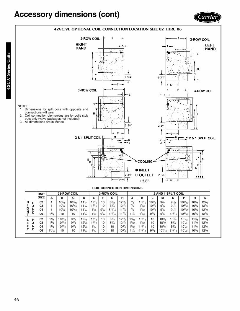
46
Accessory dimensions (cont)
42VC,VE OPTIONAL COIL CONNECTION LOCATION SIZE 02 THRU 06
NOTES:1. Dimensions for split coils with opposite end
connections will vary.2. Coil connection diemsnions are for coils stub
outs only (valve packages not included).3. All dimensions are in inches.
COIL CONNECTION DIMENSIONS
UNITSIZE
23-ROW COIL 3-ROW COIL 2 AND 1 SPLIT COILA B C D E F G H J K L M N P R S
RIGHT
HAND
02 1 103/8 107/16 111/4 15/16 10 83/8 121/2 7/8 115/16 101/8 93/4 91/2 109/16 101/4 123/803 1 103/8 107/16 111/4 15/16 10 83/8 121/2 7/8 15/16 101/8 93/4 91/2 109/16 101/4 123/804 1 103/8 107/16 111/4 11/2 93/4 815/16 117/8 7/8 15/16 101/8 93/4 91/2 109/16 101/4 123/806 11/4 10 10 113/4 11/2 93/4 815/16 117/8 11/4 15/16 93/4 93/4 815/16 109/16 103/4 123/8
LEFT
HAND
02 11/4 103/16 91/4 123/8 15/16 10 83/8 121/2 11/16 115/16 10 103/8 103/8 101/2 113/8 123/803 11/4 103/16 91/4 123/8 15/16 10 83/8 121/2 11/16 15/16 10 103/8 83/8 101/2 113/8 123/804 11/4 103/16 91/4 123/8 11/4 10 10 103/4 11/16 115/16 10 103/8 83/8 101/2 113/8 123/806 17/16 10 10 113/4 11/4 10 10 103/4 11/4 115/16 93/4 107/16 815/16 101/2 103/4 123/8
42
C,V
Ser
ies
Uni
ts
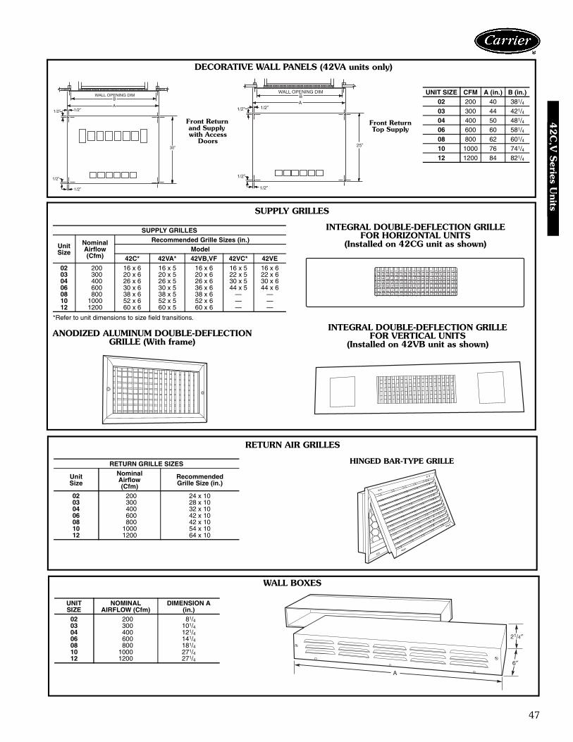
47
1/2”1/2”
B
A
WALL OPENING DIM
30”
1/2”
1/2”
1/2”
1/2”
1/2”
1/2”AB
WALL OPENING DIM
25”
DECORATIVE WALL PANELS (42VA units only)
SUPPLY GRILLES
*Refer to unit dimensions to size field transitions.
SUPPLY GRILLES
UnitSize
NominalAirflow(Cfm)
Recommended Grille Sizes (in.)Model
42C* 42VA* 42VB,VF 42VC* 42VE02 200 16 x 6 16 x 5 16 x 6 16 x 5 16 x 603 300 20 x 6 20 x 5 20 x 6 22 x 5 22 x 604 400 26 x 6 26 x 5 26 x 6 30 x 5 30 x 606 600 30 x 6 30 x 5 36 x 6 44 x 5 44 x 608 800 38 x 6 38 x 5 38 x 6 — —10 1000 52 x 6 52 x 5 52 x 6 — —12 1200 60 x 6 60 x 5 60 x 6 — —
INTEGRAL DOUBLE-DEFLECTION GRILLEFOR HORIZONTAL UNITS
(Installed on 42CG unit as shown)
INTEGRAL DOUBLE-DEFLECTION GRILLEFOR VERTICAL UNITS
(Installed on 42VB unit as shown)ANODIZED ALUMINUM DOUBLE-DEFLECTION
GRILLE (With frame)
RETURN AIR GRILLES
RETURN GRILLE SIZES
UnitSize
NominalAirflow(Cfm)
RecommendedGrille Size (in.)
02 200 24 x 1003 300 28 x 1004 400 32 x 1006 600 42 x 1008 800 42 x 1010 1000 54 x 1012 1200 64 x 10
HINGED BAR-TYPE GRILLE
WALL BOXES
UNITSIZE
NOMINALAIRFLOW (Cfm)
DIMENSION A(in.)
02 200 81/403 300 101/404 400 121/406 600 141/408 800 181/410 1000 271/412 1200 271/4
UNIT SIZE CFM A (in.) B (in.)02 200 40 381/403 300 44 421/404 400 50 481/406 600 60 581/408 800 62 601/410 1000 76 741/412 1200 84 821/4
Front Returnand Supply with Access
Doors
Front ReturnTop Supply
42C
,V S
eries Units

48
42CA,CE,CF,CG,CK,VA,VB,VF COOLING CAPACITY (by GPM) 3-ROW COIL
42CA,CE,CF,CG,CK,VA,VB,VF COOLING CAPACITY (by GPM) 4-ROW COIL
LEGEND
NOTE: All capacities are given in thousands of Btuh (MBtuh).
UNITSIZE GPM
75 F DB/63 F WB 80 F DB/67 F WB 85 F DB/71 F WB40 F EWT 45 F EWT 50 F EWT 40 F EWT 45 F EWT 50 F EWT 40 F EWT 45 F EWT 50 F EWT
∆T TCb SCb ∆T TCb SCb ∆T TCb SCb ∆T TCb SCb ∆T TCb SCb ∆T TCb SCb ∆T TCb SCb ∆T TCb TCb ∆T TCb SCb
02
1 10.4 5.2 4.2 8.5 4.3 3.8 6.8 3.4 3.3 12.5 6.2 4.7 10.5 5.2 4.2 8.6 4.3 3.8 14.8 7.4 5.1 12.7 6.4 4.7 10.6 5.3 4.31.5 8.1 6.1 4.6 6.5 4.9 4.1 5.1 3.8 3.6 9.8 7.4 5.1 8.2 6.2 4.6 6.6 4.9 4.1 11.7 8.8 5.6 10.1 7.5 5.1 8.3 6.2 4.62 6.6 6.6 4.9 5.3 5.3 4.3 4.0 4.0 3.7 8.1 8.1 5.4 6.7 6.7 4.8 5.3 5.3 4.3 9.7 9.7 6.0 8.2 8.2 5.4 6.7 6.7 4.8
2.5 5.7 7.2 5.0 4.4 5.5 4.4 3.3 4.2 3.8 6.8 8.5 5.6 5.6 7.0 5.0 4.5 5.6 4.4 8.1 10.2 6.2 6.9 8.7 5.6 5.7 7.1 5.0
031 13.1 6.5 5.6 10.9 5.5 5.1 9.0 4.5 4.4 15.6 7.8 6.2 13.2 6.6 5.7 11.0 5.5 5.1 18.3 9.1 6.7 15.8 7.9 6.2 13.3 6.7 5.7
1.5 10.3 7.8 6.2 8.4 6.3 5.6 6.7 5.0 4.9 12.5 9.4 6.9 10.5 7.9 6.3 8.5 6.4 5.6 14.8 11.1 7.5 12.7 9.5 6.9 10.6 7.9 6.32 8.6 8.6 6.6 6.9 6.9 5.9 5.4 5.4 5.1 10.5 10.5 7.3 8.7 8.7 6.6 6.9 6.96 5.9 12.5 12.5 8.0 10.6 10.6 7.3 8.7 8.7 6.63 6.4 9.5 7.0 5.1 7.6 6.2 3.9 5.8 5.4 7.8 11.7 7.8 6.4 9.7 7.0 5.1 7.6 6.2 9.3 13.9 8.6 7.9 11.9 7.8 6.5 9.8 7.0
04
1 15.5 7.8 6.9 13.1 6.5 6.2 10.7 5.4 5.3 18.4 9.2 7.6 15.7 7.8 7.0 13.2 6.6 6.3 21.4 10.7 8.2 18.6 9.3 7.7 15.8 7.9 7.11.5 12.5 9.3 7.8 10.2 7.7 7.0 8.3 6.2 6.1 15.0 11.2 8.6 12.6 9.4 7.8 10.3 7.7 7.1 17.7 13.3 9.3 15.2 11.4 8.6 12.6 9.5 7.92 10.5 10.5 8.3 8.5 8.5 7.4 6.7 6.7 6.5 12.7 12.7 9.2 10.5 10.5 8.3 8.5 8.5 7.4 15.1 15.1 10.0 12.8 12.8 9.2 10.6 10.6 8.33 7.9 11.8 8.9 6.3 9.5 7.9 4.8 7.3 6.9 9.6 14.5 9.9 8.0 12.0 8.9 6.3 9.5 7.9 11.5 17.3 10.9 9.8 14.7 9.9 8.0 12.0 8.9
3.5 7.0 12.3 9.1 5.6 9.8 8.1 4.3 7.5 7.0 8.6 15.1 10.2 7.1 12.5 9.1 5.6 9.8 8.1 10.3 18.0 11.2 8.8 15.3 10.1 7.2 12.6 9.1
06
1.5 15.0 11.3 10.1 12.9 9.7 9.0 10.5 7.8 7.8 17.6 13.2 11.1 15.4 11.5 10.2 13.2 9.9 9.2 20.4 15.3 12.0 18.0 13.5 11.2 15.7 11.8 10.42 12.8 12.8 11.0 10.9 10.9 9.9 8.8 8.8 8.8 15.3 15.3 12.1 13.1 13.1 11.2 11.1 11.1 10.1 17.9 17.9 13.1 15.6 15.6 12.2 13.4 13.4 11.33 10.1 15.1 12.1 8.3 12.5 10.9 6.8 10.1 9.6 12.2 18.3 13.4 10.3 15.4 12.2 9.4 12.7 11.1 14.4 21.6 14.6 12.4 18.7 13.4 10.4 15.6 12.34 8.4 16.7 12.9 6.8 13.6 11.5 5.4 10.7 10.1 10.2 20.3 14.3 8.5 17.0 12.9 6.8 13.6 11.5 12.1 24.1 15.6 10.3 20.7 14.2 8.5 17.1 12.95 7.1 17.8 13.3 5.7 14.3 11.8 4.4 11.1 10.3 8.7 21.7 14.8 7.2 18.0 13.3 5.7 14.3 11.9 10.3 25.8 16.2 8.8 22.0 14.7 7.3 18.1 13.3
08
2 15.6 15.6 13.7 13.4 13.4 12.3 10.8 10.8 10.8 18.3 18.3 15.0 15.9 15.9 13.9 13.6 13.6 12.5 21.2 21.2 16.2 18.7 18.7 15.2 16.3 16.3 14.13 12.3 18.5 15.2 10.3 15.5 13.8 8.5 12.7 12.0 14.7 22.1 16.8 12.5 18.8 15.4 10.4 15.7 14.0 17.3 26.0 18.2 15.0 22.5 16.9 12.7 19.0 15.54 10.3 20.5 16.2 8.4 16.9 14.6 6.8 13.5 12.8 12.4 24.7 17.9 10.4 20.8 16.3 8.5 16.9 14.7 14.2 28.4 19.5 12.6 25.2 17.9 10.5 20.9 16.36 7.3 22.0 16.9 6.2 18.6 15.4 4.8 14.4 13.5 9.3 28.0 19.3 7.8 23.3 17.4 6.2 18.6 15.5 11.1 33.4 21.1 9.5 28.5 19.2 7.8 23.5 17.48 — — — — — — — — — — — — — — — — — — — — — — — — — — —
10
3 13.2 19.8 17.5 11.4 17.1 15.8 9.0 13.5 13.5 15.5 23.2 19.1 13.6 20.4 17.8 11.7 17.6 16.1 18.0 27.0 20.7 15.9 23.9 19.4 14.0 20.9 18.14 11.3 22.6 19.0 9.6 19.2 17.2 7.5 15.1 15.1 13.5 26.9 20.9 11.6 23.1 19.2 9.8 19.6 17.5 15.8 31.6 22.5 13.8 27.6 21.1 11.8 23.6 19.55 9.9 24.7 20.0 8.3 20.6 18.1 6.8 17.0 15.9 11.9 29.7 22.0 10.1 25.3 20.2 8.4 21.0 18.4 14.0 35.0 23.9 12.2 30.4 22.2 10.3 25.7 20.46 8.8 26.4 20.8 7.3 21.8 18.8 5.9 17.7 16.5 10.6 31.9 23.0 9.0 27.0 21.0 7.4 22.2 19.0 12.6 37.8 25.0 10.9 32.7 23.1 9.1 27.4 21.18 7.2 29.0 22.0 5.9 23.7 19.7 4.6 18.6 17.2 8.8 35.3 24.4 7.4 29.7 22.1 6.0 23.8 19.8 10.5 41.9 26.6 9.0 36.2 24.4 7.5 30.0 22.1
12
3 14.9 22.4 19.9 12.9 19.4 17.9 10.2 15.3 15.3 17.4 26.2 22.0 15.4 23.1 20.3 13.3 20.0 18.3 20.2 30.3 23.8 18.0 27.0 22.4 15.8 23.8 20.64 12.8 25.7 21.9 11.0 22.0 19.9 8.6 17.2 17.2 15.2 30.4 24.0 13.2 26.3 22.3 11.2 22.5 20.1 17.7 35.5 26.0 15.6 31.1 24.3 13.5 26.9 22.65 11.3 28.1 23.1 9.5 23.7 21.0 7.8 19.6 18.3 13.4 33.6 25.4 11.5 28.8 23.4 9.7 24.2 21.3 15.8 39.5 27.6 13.8 34.4 25.7 11.7 29.3 23.76 10.1 30.2 24.2 8.3 25.0 21.8 6.8 20.5 19.1 12.1 36.3 26.6 10.3 30.8 24.4 8.5 25.5 22.0 14.3 42.9 28.6 12.4 37.1 26.7 10.4 31.2 24.58 8.3 33.2 25.6 6.8 27.3 22.9 5.4 21.6 20.1 10.1 40.3 28.3 8.5 34.0 25.7 6.9 27.5 23.1 11.9 47.8 30.8 10.3 41.3 28.4 8.6 34.3 25.7
UNITSIZE GPM
75 F DB/63 F WB 80 F DB/67 F WB 85 F DB/71 F WB40 F EWT 45 F EWT 50 F EWT 40 F EWT 45 F EWT 50 F EWT 40 F EWT 45 F EWT 50 F EWT
∆T TCb SCb ∆T TCb SCb ∆T TCb SCb ∆T TCb SCb ∆T TCb SCb ∆T TCb SCb ∆T TCb SCb ∆T TCb TCb ∆T TCb SCb
02
1 12.0 6.0 4.7 9.8 4.9 4.2 7.8 3.9 3.7 14.4 7.2 5.2 12.1 6.1 4.7 9.9 4.9 4.3 17.1 8.5 5.7 14.7 7.3 5.2 12.3 6.1 4.81.5 9.3 7.0 5.2 7.5 5.7 4.6 5.8 4.4 4.0 11.3 8.5 5.8 9.5 7.1 5.2 7.6 5.7 4.6 13.5 10.1 6.3 11.6 8.7 5.8 9.6 7.2 5.22 7.6 7.6 5.5 6.1 6.1 4.8 4.6 4.6 4.2 9.3 9.3 6.1 7.7 7.7 5.4 6.1 6.1 4.8 11.1 11.1 6.7 9.5 9.5 6.1 7.8 7.8 5.4
2.5 6.4 8.0 5.6 5.1 6.4 4.9 3.9 4.8 4.2 7.8 9.8 6.3 6.5 8.1 5.6 5.2 6.4 4.9 9.4 11.7 7.0 8.0 10.0 6.3 6.6 8.3 5.6
031 15.0 7.5 6.3 12.6 6.3 5.7 10.2 5.1 5.0 17.9 9.0 6.9 15.2 7.6 6.4 12.6 6.3 5.8 21.0 10.5 7.5 18.2 9.1 7.0 15.3 7.7 6.4
1.5 12.0 9.0 7.0 9.8 7.3 6.3 7.7 5.8 5.5 14.4 10.8 7.7 12.1 9.1 7.0 9.8 7.4 6.3 17.1 12.8 8.4 14.7 11.0 7.7 12.2 9.1 7.02 10.0 10.0 7.5 8.0 8.0 6.6 6.2 6.2 5.8 12.1 12.1 8.3 10.0 10.0 7.4 8.0 8.0 6.6 14.3 14.3 9.1 12.2 12.2 8.2 10.1 10.1 7.43 7.4 11.0 8.0 5.9 8.9 7.0 4.5 6.7 6.1 9.0 13.5 8.9 7.5 11.2 7.9 5.9 8.9 7.0 10.8 16.1 9.8 9.2 13.8 8.8 7.6 11.4 7.9
04
1 17.9 8.9 7.8 15.0 7.5 7.0 12.3 6.2 6.1 21.1 10.5 8.5 18.0 9.0 7.8 15.1 7.6 7.0 24.5 12.2 9.2 21.3 10.6 8.6 18.2 9.1 7.91.5 14.4 10.8 8.8 11.8 8.9 7.9 9.5 7.1 6.9 17.2 12.9 9.6 14.5 10.9 8.8 11.9 8.9 7.9 20.3 15.2 10.5 17.5 13.1 9.6 14.6 10.9 8.82 12.1 12.1 9.4 9.8 9.8 8.3 7.7 7.7 7.3 14.6 14.6 10.4 12.2 12.2 9.4 9.8 9.8 8.4 17.4 17.4 11.3 14.8 14.8 10.3 12.2 12.2 9.43 9.2 13.8 10.2 7.4 11.0 8.9 5.6 8.4 7.8 11.2 16.8 11.3 9.3 13.9 10.1 7.4 11.1 9.0 13.3 20.0 12.4 11.4 17.0 11.2 9.3 14.0 10.1
3.5 8.2 14.3 10.4 6.6 11.5 9.1 5.0 8.7 7.9 10.0 17.5 11.6 8.3 14.5 10.4 6.6 11.5 9.1 11.9 20.9 12.8 10.2 17.8 11.5 8.4 14.7 10.3
06
1.5 18.0 13.5 11.6 15.5 11.6 10.4 12.3 9.2 9.2 20.9 15.7 12.7 18.4 13.8 11.7 15.9 11.9 10.6 24.1 18.1 13.6 21.4 16.1 12.8 18.9 14.1 11.92 15.3 15.3 12.6 13.1 13.1 11.4 10.9 10.9 10.0 18.1 18.1 13.8 15.6 15.6 12.7 13.3 13.3 11.6 21.1 21.1 14.9 18.5 18.5 13.9 16.0 16.0 12.93 12.0 18.0 13.9 9.9 14.9 12.5 8.1 12.1 11.1 14.4 21.6 15.4 12.2 18.3 14.0 10.1 15.1 12.6 17.0 25.5 16.7 14.7 22.0 15.4 12.4 18.5 14.04 12.0 18.0 13.9 9.9 14.9 12.5 8.1 12.1 11.1 14.4 21.6 15.4 12.2 18.3 14.0 10.1 15.1 12.6 17.0 25.5 16.7 14.7 22.0 15.4 12.4 18.5 14.05 9.9 19.8 14.8 8.1 16.2 13.2 6.4 12.8 11.6 12.0 23.9 16.4 10.0 20.1 14.8 8.1 16.3 13.2 14.2 28.4 17.9 12.2 24.4 16.3 10.1 20.3 14.7
08
2 18.5 18.5 15.7 15.9 15.9 14.1 13.4 13.4 12.3 21.6 21.6 17.1 18.9 18.9 15.8 16.3 16.3 14.3 24.9 24.9 18.4 22.0 22.0 17.2 19.3 19.3 15.93 14.6 21.9 17.5 12.3 18.4 15.8 10.2 15.2 14.0 17.3 26.0 19.2 14.9 22.3 17.6 12.4 18.6 15.9 20.3 30.4 20.8 17.7 26.5 19.2 15.0 22.5 17.74 12.1 24.3 18.6 10.0 20.0 16.7 8.1 16.2 14.8 14.6 29.2 20.6 12.3 24.6 18.6 10.1 20.2 16.8 17.2 34.4 22.4 14.8 29.6 20.5 12.4 24.8 18.76 9.1 27.2 20.0 7.3 22.0 17.7 5.7 17.2 15.5 11.0 33.0 22.2 9.2 27.6 19.9 7.4 22.2 17.7 13.1 39.2 24.3 11.2 33.6 22.1 9.3 27.8 19.98 — — — — — — — — — — — — — — — — — — — — — — — — — — —
10
3 16.0 24.0 20.1 13.9 20.8 18.4 10.6 15.9 15.9 18.7 28.0 22.1 16.4 24.7 20.4 14.3 21.5 18.7 21.6 32.4 23.8 19.2 28.8 22.3 17.0 25.5 20.84 13.6 27.2 21.9 11.6 23.2 19.9 9.7 19.5 17.6 16.1 32.3 24.0 14.0 27.9 22.1 11.9 23.8 20.3 18.8 37.7 25.9 16.5 33.1 24.1 14.3 28.5 22.45 11.9 29.7 23.1 10.0 24.9 20.9 8.2 20.5 18.5 14.2 35.5 25.4 12.1 30.4 23.3 10.2 25.4 21.1 16.7 41.7 27.6 14.5 36.3 25.5 12.4 31.0 23.46 10.5 31.6 24.0 8.8 26.3 21.6 7.1 21.3 19.2 12.7 38.1 26.5 10.8 32.3 24.1 8.9 26.7 21.8 15.0 45.0 28.9 13.0 39.0 26.5 11.0 32.9 24.28 8.6 34.6 25.4 7.1 28.4 22.6 5.6 22.3 19.8 10.5 41.8 28.2 8.8 35.3 25.4 7.1 28.6 22.6 12.4 49.6 30.8 10.7 43.0 28.1 8.9 35.8 25.4
12
3 18.1 27.2 23.1 15.8 23.7 20.9 12.0 18.0 18.0 21.1 31.6 25.3 18.7 28.0 23.4 16.4 24.6 21.3 24.2 36.3 27.2 21.7 32.5 25.6 19.3 29.0 23.94 15.5 30.9 25.3 13.3 26.6 23.0 11.3 22.5 20.3 18.2 36.5 27.7 15.9 31.8 25.6 13.7 27.4 23.4 21.2 42.3 29.8 18.7 37.3 27.8 16.3 32.6 25.95 13.5 33.8 26.8 11.5 28.6 24.3 9.6 23.9 21.5 16.1 40.2 29.4 13.8 34.6 27.0 11.7 29.3 24.5 18.8 47.1 31.8 16.5 41.1 29.5 14.1 35.4 27.26 12.0 36.1 27.9 10.1 30.2 25.2 8.3 24.9 22.3 14.4 43.3 30.7 12.3 36.9 28.0 10.2 30.7 25.4 17.0 50.9 33.3 14.8 44.3 30.7 12.5 37.5 28.18 9.9 39.6 29.5 8.2 32.7 26.5 6.5 26.1 23.3 12.0 47.8 32.7 10.1 40.5 29.6 8.3 33.0 26.5 14.3 57.1 35.9 12.3 49.1 32.7 10.3 41.0 29.6
∆T — Temperature Change SCb — Base Sensible Capacity from Base Cooling Capacities by Gpm chartsDB — Dry Bulb TCb — Base Total Capacity from Base Cooling Capacities by Gpm chartsEWT — Entering Water Temperature WB — Wet BulbGPM — Gallons Per Minute
Performance data42
C,V
Ser
ies
Uni
ts

49
42CA,CE,CF,CG,CK,VA,VB,VF COOLING CAPACITY (by ∆T) 3-ROW COIL
42CA,CE,CF,CG,CK,VA,VB,VF COOLING CAPACITY (by ∆T) 4-ROW COIL
LEGEND
NOTE: All capacities are given in thousands of Btuh (MBtuh).
UNITSIZE ∆T
75 F DB/63 F WB 80 F DB/67 F WB 85 F DB/71 F WB40 F EWT 45 F EWT 50 F EWT 40 F EWT 45 F EWT 50 F EWT 40 F EWT 45 F EWT 50 F EWT
GPM TCb SCb GPM TCb SCb GPM TCb SCb GPM TCb SCb GPM TCb SCb GPM TCb SCb GPM TCb SCb GPM TCb SCb GPM TCb SCb
02
8 1.5 6.1 4.6 1.1 4.4 3.9 0.8 3.2 3.2 2.0 8.1 5.4 1.6 6.2 4.7 1.1 4.5 3.9 2.6 10.2 6.2 2.1 8.3 5.4 1.6 6.3 4.710 1.1 5.3 4.3 0.8 3.9 3.6 0.6 3.0 2.9 1.5 7.3 5.1 1.1 5.4 4.3 0.8 3.9 3.6 0.0 9.5 5.9 1.5 7.6 5.1 1.1 5.6 4.412 0.8 4.7 4.0 0.6 3.4 3.2 — — — 1.1 6.5 4.7 0.8 4.8 4.0 0.6 3.4 3.3 1.5 8.7 5.6 1.1 6.7 4.8 0.8 4.9 4.114 0.6 4.1 3.6 — — — — — — 0.8 5.7 4.4 0.6 4.2 3.7 — — — 1.1 7.7 5.2 0.8 5.9 4.5 0.6 4.3 3.816 — — — — — — — — — 0.6 5.0 4.1 — — — — — — 0.9 6.9 4.9 0.6 5.1 4.1 — — —
03
8 2.2 8.9 6.7 1.6 6.5 5.7 1.2 4.7 4.6 2.9 11.6 7.8 2.2 9.0 6.7 1.6 6.5 5.7 — — — — — — 2.3 9.0 6.710 1.6 7.9 6.3 1.2 5.8 5.3 0.9 4.3 4.2 2.1 10.7 7.4 1.6 8.1 6.4 1.2 5.8 5.3 2.7 13.6 8.5 2.2 10.9 7.4 1.6 8.2 6.412 1.2 7.0 5.9 0.9 5.1 4.8 0.6 3.9 3.8 1.6 9.7 7.0 1.2 7.2 5.9 0.9 5.2 4.9 2.1 12.7 8.1 1.7 9.9 7.0 1.2 7.3 6.014 0.9 6.2 5.4 0.6 4.5 4.3 — — — 1.2 8.6 6.5 0.9 6.3 5.5 0.7 4.6 4.4 1.7 11.6 7.7 1.3 8.9 6.6 0.9 6.4 5.616 0.7 5.5 5.0 — — — — — — 1.0 7.6 6.1 0.7 5.6 6.0 — — — 1.3 10.5 7.2 1.0 7.8 6.2 0.7 5.7 5.1
04
8 3.0 11.8 8.9 2.2 8.7 7.5 1.6 6.3 6.2 — — — 3.0 12.0 8.9 2.2 8.7 7.5 — — — — — — — — —10 2.1 10.7 8.4 1.6 7.8 7.0 1.1 5.6 5.6 2.9 14.3 9.9 2.2 10.8 8.4 1.6 7.8 7.1 — — — — — — 2.2 10.9 8.512 1.6 9.6 7.9 1.2 7.0 6.5 0.8 5.0 5.0 2.2 13.1 9.4 1.6 9.8 7.9 1.2 7.0 6.6 2.8 17.0 10.8 2.2 13.3 9.3 1.6 9.8 8.014 1.2 8.5 7.3 0.9 6.2 5.9 0.6 4.4 4.4 1.7 11.9 8.8 1.2 8.7 7.4 0.9 6.3 6.0 2.3 15.8 10.3 1.7 12.1 8.9 1.3 8.8 7.516 0.9 7.5 6.8 0.7 5.6 5.4 — — — 1.3 10.6 8.3 1.0 7.7 6.9 0.7 5.7 5.5 1.8 14.4 9.8 1.4 10.9 8.4 1.0 7.8 7.0
06
8 4.3 17.0 13.0 3.2 12.7 11.0 2.4 9.5 9.1 5.6 22.2 15.1 4.3 17.3 13.1 3.2 12.9 11.2 7.0 27.9 17.1 — — — 4.4 17.5 13.110 3.1 15.2 12.2 2.3 11.4 10.3 1.6 8.1 8.1 4.1 20.4 14.3 3.1 15.6 12.3 2.4 11.8 10.5 5.2 26.1 16.4 4.2 21.0 14.3 3.2 15.9 12.412 2.3 13.5 11.3 1.7 10.2 9.4 1.1 6.8 6.8 3.1 18.5 13.5 2.3 14.0 11.6 1.8 10.6 9.7 4.0 24.2 15.6 3.2 19.1 13.6 2.4 14.4 11.814 1.7 12.0 10.5 1.2 8.6 8.3 — — — 2.4 16.5 12.6 1.8 12.5 10.8 1.3 9.1 8.7 3.2 22.1 14.8 2.4 17.1 12.8 1.9 12.9 11.016 1.3 10.5 9.6 — — — — — — 1.8 14.6 11.8 1.4 11.1 9.9 — — — 2.5 19.9 13.9 1.9 15.2 12.0 1.5 11.6 10.2
08
8 5.7 22.7 17.3 4.3 17.2 14.7 3.2 12.9 12.3 — — — — — — 4.3 17.3 14.8 — — — — — — — — —10 4.2 20.8 16.4 3.1 15.7 13.9 2.3 11.3 11.3 5.5 27.3 19.0 4.2 21.2 16.5 3.2 15.9 14.1 6.9 34.6 21.6 5.6 27.9 19.0 4.3 21.4 16.512 3.1 18.8 15.4 2.4 14.3 13.0 1.7 9.9 9.9 4.2 25.2 18.1 3.2 19.3 15.6 2.5 14.7 13.3 5.4 32.4 20.7 4.3 25.8 18.2 3.3 19.6 15.714 2.4 16.9 14.4 1.8 12.9 11.9 1.2 8.2 49.9 3.3 22.9 17.1 2.5 17.5 14.7 1.9 13.4 12.2 4.1 28.8 19.7 3.4 23.6 17.3 2.6 18.0 15.016 1.9 15.3 13.4 1.4 11.1 10.5 — — — 2.6 20.7 16.2 2.0 15.9 13.9 1.5 11.9 11.1 3.4 27.0 18.8 2.7 21.4 16.4 2.1 16.5 14.2
10
8 6.9 27.8 21.4 5.2 21.0 18.3 3.6 14.6 14.6 9.2 36.7 25.0 7.2 28.7 21.7 5.4 21.5 18.6 11.6 46.2 28.4 9.5 37.8 25.0 7.3 29.2 21.810 4.9 24.6 19.9 3.7 18.7 16.9 2.5 12.3 12.3 6.6 33.1 23.5 5.1 25.4 20.3 3.9 19.4 17.3 8.6 42.8 27.0 6.9 34.4 23.7 5.2 26.2 20.612 3.6 21.6 18.4 2.6 15.6 14.8 — — — 4.9 29.5 21.9 3.8 22.6 18.9 2.8 26.9 15.6 6.5 39.0 25.5 5.1 30.7 22.3 3.9 23.4 19.414 2.7 18.6 16.7 — — — — — — 3.7 25.9 20.4 2.8 19.8 17.4 — — — 5.0 35.1 23.9 3.8 26.7 21.0 3.0 20.9 18.116 — — — — — — — — — 2.8 22.4 18.7 2.1 17.1 15.5 — — — 3.9 31.1 22.4 3.0 23.8 19.4 2.3 18.4 16.3
12
8 8.5 33.8 25.8 6.4 25.6 22.0 4.8 19.1 18.1 11.1 44.2 30.0 8.7 34.7 26.0 6.5 26.1 22.4 13.8 55.3 33.9 — — — 7.3 29.2 21.810 6.1 30.3 24.2 4.6 23.1 20.6 3.1 15.5 15.5 8.1 40.4 28.3 6.2 31.2 24.6 4.8 23.8 21.1 10.4 51.9 32.5 8.4 41.9 28.6 5.2 26.2 20.612 4.5 27.0 22.6 3.4 20.6 18.9 2.1 12.3 12.3 6.1 36.4 26.7 4.7 28.0 23.1 3.6 21.6 19.5 8.0 47.7 30.8 6.3 37.9 27.0 3.9 23.4 19.414 3.4 23.8 20.8 2.3 16.0 15.5 — — — 4.7 32.6 25.0 3.6 25.1 21.5 2.5 17.7 16.7 6.2 43.5 29.2 4.9 33.9 25.5 3.0 20.9 18.116 2.6 20.5 18.5 — — — — — — 3.6 28.9 23.3 2.8 22.1 19.5 — — — 4.9 39.2 27.5 3.8 30.4 23.9 2.3 18.4 16.3
UNITSIZE ∆T
75 F DB/63 F WB 80 F DB/67 F WB 85 F DB/71 F WB40 F EWT 45 F EWT 50 F EWT 40 F EWT 45 F EWT 50 F EWT 40 F EWT 45 F EWT 50 F EWT
GPM TCb SCb GPM TCb SCb GPM TCb SCb GPM TCb SCb GPM TCb SCb GPM TCb SCb GPM TCb SCb GPM TCb SCb GPM TCb SCb
02
8 1.9 7.5 5.4 1.4 5.5 4.5 1.0 3.9 3.7 2.4 9.7 6.3 1.9 7.6 5.4 1.4 5.6 4.6 3.0 12.2 7.2 2.5 10.0 6.3 1.9 7.8 5.410 1.4 6.7 5.1 1.0 4.9 4.2 0.7 3.6 3.5 1.8 9.0 6.0 1.4 6.9 5.1 1.0 4.9 4.3 2.3 11.5 6.9 1.9 9.3 6.0 1.4 7.1 5.112 1.0 6.0 4.7 0.7 4.3 3.9 0.6 3.4 3.3 1.4 8.2 5.7 1.0 6.1 4.8 0.7 4.4 3.9 1.8 10.8 6.6 1.4 8.5 5.7 1.0 6.2 4.814 0.8 5.4 4.4 0.6 3.8 3.6 — — — 1.1 7.4 5.3 0.8 5.5 4.5 0.6 3.9 3.6 1.4 9.9 6.2 1.1 7.6 5.3 0.8 5.6 4.516 0.6 4.7 4.1 — — — — — — 0.8 6.6 5.0 0.6 4.8 4.1 — — — 1.1 9.0 5.9 0.9 6.8 5.0 0.6 4.9 4.2
03
8 2.7 10.8 7.8 2.0 8.0 6.6 1.4 5.7 5.5 3.5 14.0 9.1 2.7 11.0 7.8 2.0 8.0 6.6 — — — — — — 2.8 11.1 7.810 2.0 9.9 7.4 1.5 7.2 6.2 1.0 5.2 5.1 2.6 13.0 8.7 2.0 10.0 7.4 1.5 7.3 6.3 3.3 16.5 10.0 2.7 13.4 8.7 2.0 10.1 7.412 1.5 9.0 7.0 1.1 6.5 5.8 0.8 4.8 4.7 2.0 12.1 8.3 1.5 9.1 7.0 1.1 6.6 5.9 2.6 15.5 9.5 2.1 12.4 8.3 1.5 9.2 7.114 1.1 8.0 6.6 0.8 5.8 5.3 0.6 4.4 4.3 1.6 11.1 7.8 1.2 8.2 6.6 0.8 5.9 5.4 2.1 14.5 9.1 1.6 11.4 7.9 1.2 8.3 6.716 0.9 7.2 6.1 0.6 5.1 4.8 0.5 4.0 4.0 1.3 10.0 7.4 0.9 7.3 6.2 0.7 5.2 4.9 1.7 13.4 8.7 1.3 10.3 7.4 0.9 7.4 6.3
04
8 — — — 2.7 10.7 8.8 1.9 7.5 7.3 — — — — — — 2.7 10.7 8.8 — — — — — — — — —10 2.7 13.3 9.9 2.0 9.7 8.3 1.4 7.0 6.8 3.5 17.5 11.6 2.7 13.5 9.9 2.0 9.7 8.4 — — — — — — 2.7 13.6 9.912 2.0 12.2 9.4 1.5 8.8 7.8 1.0 6.3 6.2 2.7 16.3 11.1 2.1 12.3 9.4 1.5 8.9 7.9 3.5 20.9 12.8 2.8 16.6 11.1 2.1 12.4 9.414 1.6 11.0 8.9 1.1 7.9 7.3 0.8 5.7 5.6 2.2 15.0 10.6 1.6 11.2 8.9 1.2 8.0 7.3 2.8 19.6 12.2 2.2 15.3 10.5 1.6 11.3 8.916 1.2 9.9 8.3 0.9 7.2 6.7 0.6 5.1 5.0 1.7 13.7 10.0 1.3 10.1 8.4 0.9 7.3 6.8 2.3 18.3 11.7 1.8 14.0 10.0 1.3 10.2 8.4
06
8 5.3 21.3 15.5 4.1 16.2 13.2 3.0 12.2 11.1 6.8 27.4 17.9 5.4 21.7 15.5 4.1 16.3 13.2 — — — — — — 5.5 22.1 15.410 3.9 19.7 14.7 3.0 14.9 12.5 2.3 11.3 10.4 5.1 25.7 17.1 4.0 20.1 14.8 3.0 15.2 12.7 6.5 32.3 19.5 5.3 26.4 17.1 4.1 20.4 14.812 3.0 18.0 13.9 2.3 13.7 11.8 1.6 9.5 9.4 4.0 23.9 16.4 3.1 18.5 14.1 2.3 14.0 12.0 5.1 30.4 18.7 4.1 24.6 16.4 3.1 18.8 14.114 2.3 16.3 13.1 1.8 12.5 11.1 1.1 8.0 8.0 3.1 22.0 15.5 2.4 16.9 13.3 1.9 12.9 11.3 4.1 28.6 18.0 3.2 22.7 15.6 2.5 17.4 13.616 1.9 14.8 12.3 1.4 11.3 10.1 — — — 2.5 20.1 14.7 1.9 15.4 12.6 1.5 11.8 10.5 3.3 26.5 17.1 2.6 20.8 14.9 2.0 15.9 12.9
08
8 — — — 5.4 21.5 17.5 4.1 16.2 14.8 — — — — — — 5.4 21.7 17.5 — — — — — — — — —10 5.3 26.3 19.6 4.0 20.0 16.7 3.1 15.3 14.0 6.8 34.0 22.7 5.4 26.8 19.6 4.0 20.2 16.8 — — — 7.0 34.9 22.6 5.4 27.1 19.612 4.1 24.4 18.7 3.1 18.6 15.9 2.4 14.3 13.1 5.3 31.9 21.8 4.2 24.9 18.8 3.2 18.9 16.1 6.7 40.4 24.8 5.4 32.7 21.7 4.2 25.2 18.814 3.2 22.4 17.7 2.5 17.2 15.1 1.8 12.3 11.7 4.3 29.8 20.9 3.3 23.1 18.0 2.5 17.8 15.4 5.5 38.1 23.9 4.4 30.5 20.8 3.3 23.4 18.116 2.6 20.5 16.8 2.0 15.8 14.1 1.2 9.7 9.7 3.5 27.6 19.9 2.7 21.2 17.1 2.1 16.5 14.5 4.5 35.8 23.0 3.5 28.3 20.0 2.7 21.8 17.3
10
8 8.9 35.5 25.8 6.8 27.2 22.1 5.2 20.7 18.6 11.4 45.7 29.9 9.1 36.4 25.9 6.9 27.7 22.2 — — — 11.8 47.0 29.7 9.3 37.1 25.910 6.5 32.5 24.4 5.0 24.9 20.9 3.7 18.4 17.1 8.5 42.6 28.5 6.7 33.6 24.6 5.1 25.6 21.2 10.8 53.8 32.5 8.8 44.1 28.5 6.9 34.3 24.812 4.9 29.5 23.0 3.8 22.8 19.7 2.4 14.2 14.2 6.5 39.2 27.0 5.1 30.6 23.4 4.0 23.8 20.2 8.4 50.4 31.1 6.8 40.8 27.2 5.3 31.5 23.614 3.8 26.7 21.6 3.0 20.7 18.3 — — — 5.1 35.8 25.5 4.0 27.8 22.1 3.1 21.8 18.9 6.7 46.8 30.8 5.3 37.3 25.8 4.1 28.9 22.516 3.0 23.9 20.1 2.3 18.2 16.3 — — — 4.1 32.5 24.1 3.2 25.2 20.7 2.4 19.5 17.2 5.4 43.1 28.1 4.2 33.9 24.5 3.3 26.6 21.4
12
8 10.7 42.8 31.0 8.2 32.9 26.5 6.3 25.0 22.5 13.0 52.1 35.7 10.9 43.7 31.0 8.3 33.3 26.6 — — — — — — 11.1 44.4 30.910 7.9 39.5 29.5 6.1 30.3 25.2 4.7 23.6 21.2 10.3 51.5 34.3 8.2 40.7 29.7 6.2 31.0 25.5 12.9 64.5 38.9 10.6 52.9 34.2 8.3 41.4 29.712 6.0 36.2 27.9 4.7 28.0 23.9 3.0 18.0 18.0 8.0 47.7 32.6 6.2 37.4 28.3 4.8 29.0 24.4 10.2 61.0 37.5 8.3 49.5 32.8 6.4 38.2 28.414 4.7 33.1 26.4 3.7 25.8 22.4 2.1 14.8 14.8 6.3 44.1 31.0 4.9 34.4 26.9 3.9 27.1 23.1 8.2 57.5 36.0 6.5 45.7 31.3 5.1 35.5 27.316 3.8 30.2 24.8 2.8 22.7 20.3 — — — 5.1 40.4 29.4 4.0 31.6 25.5 3.1 25.0 21.6 6.7 53.2 34.3 5.3 42.0 29.8 4.1 33.0 26.1
∆T — Temperature Change SCb — Base Sensible Capacity from Base Cooling Capacities by Gpm chartsDB — Dry Bulb TCb — Base Total Capacity from Base Cooling Capacities by Gpm chartsEWT — Entering Water Temperature WB — Wet BulbGPM — Gallons Per Minute
42
C,V
Series U
nits
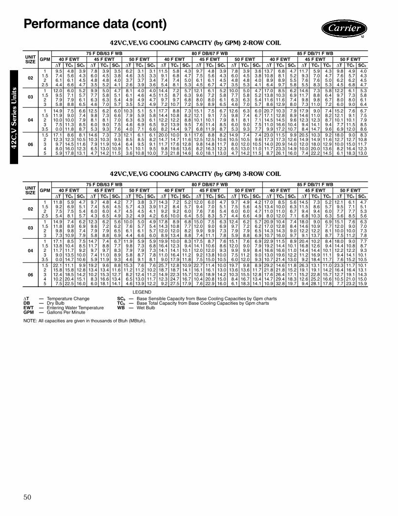
50
42VC,VE,VG COOLING CAPACITY (by GPM) 2-ROW COIL
42VC,VE,VG COOLING CAPACITY (by GPM) 3-ROW COIL
LEGEND
NOTE: All capacities are given in thousands of Btuh (MBtuh).
UNITSIZE GPM
75 F DB/63 F WB 80 F DB/67 F WB 85 F DB/71 F WB40 F EWT 45 F EWT 50 F EWT 40 F EWT 45 F EWT 50 F EWT 40 F EWT 45 F EWT 50 F EWT
∆T TCb SCb ∆T TCb SCb ∆T TCb SCb ∆T TCb SCb ∆T TCb SCb ∆T TCb SCb ∆T TCb SCb ∆T TCb TCb ∆T TCb SCb
02
1 9.5 4.8 3.9 7.8 3.9 3.5 6.2 3.1 3.1 11.5 5.8 4.3 9.7 4.8 3.9 7.8 3.9 3.6 13.7 6.8 4.7 11.7 5.9 4.3 9.8 4.9 4.01.5 7.4 5.6 4.3 6.0 4.5 3.8 4.6 3.5 3.3 9.1 6.8 4.7 7.5 5.6 4.3 6.0 4.5 3.8 10.8 8.1 5.2 9.3 7.0 4.7 7.6 5.7 4.32 6.1 6.1 4.5 4.8 4.8 4.0 3.7 3.7 3.4 7.4 7.4 5.0 6.1 6.1 4.5 4.8 4.8 4.0 8.9 8.9 5.5 7.6 7.6 5.0 6.2 6.2 4.5
2.5 4.4 6.6 4.7 3.5 5.2 4.1 2.6 3.9 3.6 5.4 8.1 5.3 4.5 6.7 4.7 3.5 5.3 4.1 6.4 9.7 5.8 5.5 8.3 5.3 4.5 6.8 4.7
031 12.0 6.0 5.2 9.9 5.0 4.7 8.1 4.0 4.0 14.4 7.2 5.7 12.1 6.1 5.2 10.0 5.0 4.7 17.0 8.5 6.2 14.6 7.3 5.8 12.2 6.1 5.3
1.5 9.5 7.1 5.7 7.7 5.8 5.1 6.1 4.6 4.5 11.5 8.7 6.3 9.6 7.2 5.8 7.7 5.8 5.2 13.8 10.3 6.9 11.7 8.8 6.4 9.7 7.3 5.82 7.9 7.9 6.1 6.3 6.3 5.4 4.9 4.9 4.7 9.7 9.7 6.8 8.0 8.0 6.1 6.3 6.3 5.4 11.6 11.6 7.4 9.8 9.8 6.7 8.0 8.0 6.13 5.8 8.8 6.5 4.6 7.0 5.7 3.5 5.2 4.9 7.2 10.7 7.2 5.9 8.9 6.5 4.6 7.0 5.7 8.6 12.9 8.0 7.3 11.0 7.2 6.0 9.0 6.4
04
1 14.9 7.5 6.6 12.5 6.2 6.0 10.3 5.1 5.1 17.7 8.8 7.3 15.1 7.5 6.7 12.6 6.3 6.0 20.7 10.3 7.9 17.9 9.0 7.4 15.2 7.6 6.71.5 11.9 9.0 7.4 9.8 7.3 6.6 7.9 5.9 5.8 14.4 10.8 8.2 12.1 9.1 7.5 9.8 7.4 6.7 17.1 12.8 8.9 14.6 11.0 8.2 12.1 9.1 7.52 10.0 10.0 7.9 8.1 8.1 7.0 6.3 6.3 6.1 12.2 12.2 8.8 10.1 10.1 7.9 8.1 8.1 7.1 14.5 14.5 9.6 12.3 12.3 8.7 10.1 10.1 7.93 7.5 11.3 8.5 6.0 9.0 7.5 4.6 6.9 6.5 9.2 13.9 9.5 7.6 11.4 8.5 6.0 9.0 7.5 11.0 16.6 10.4 9.4 14.1 9.4 7.7 11.5 8.5
3.5 0.0 11.8 8.7 5.3 9.3 7.6 4.0 7.1 6.6 8.2 14.4 9.7 6.8 11.9 8.7 5.3 9.3 7.7 9.9 17.2 10.7 8.4 14.7 9.6 6.9 12.0 8.6
06
1.5 17.1 8.6 8.1 14.6 7.3 7.3 12.1 6.1 6.1 20.0 10.0 9.1 17.6 8.8 8.2 14.9 7.4 7.4 23.0 11.5 9.9 20.5 10.3 9.2 18.0 9.0 8.32 12.3 12.3 10.5 10.3 10.3 9.5 8.5 8.5 8.2 14.7 14.7 11.6 12.5 12.5 10.6 10.5 10.5 9.6 17.3 17.3 12.6 14.9 14.9 11.6 12.7 12.7 10.83 9.7 14.5 11.6 7.9 11.9 10.4 6.4 9.5 9.1 11.7 17.6 12.8 9.8 14.8 11.7 8.0 12.0 10.5 14.0 20.9 14.0 12.0 18.0 12.9 10.0 15.0 11.74 8.0 16.0 12.3 6.5 13.0 10.9 5.1 10.1 9.5 9.8 19.6 13.6 8.2 16.3 12.3 6.5 13.0 11.0 11.7 23.3 14.9 10.0 20.0 13.6 8.2 16.4 12.35 5.9 17.8 13.1 4.7 14.2 11.5 3.6 10.8 10.0 7.3 21.8 14.6 6.0 18.1 13.0 4.7 14.2 11.5 8.7 26.1 16.0 7.4 22.2 14.5 6.1 18.3 13.0
UNITSIZE GPM
75 F DB/63 F WB 80 F DB/67 F WB 85 F DB/71 F WB40 F EWT 45 F EWT 50 F EWT 40 F EWT 45 F EWT 50 F EWT 40 F EWT 45 F EWT 50 F EWT
∆T TCb SCb ∆T TCb SCb ∆T TCb SCb ∆T TCb SCb ∆T TCb SCb ∆T TCb SCb ∆T TCb SCb ∆T TCb TCb ∆T TCb SCb
02
1 11.8 5.9 4.7 9.7 4.8 4.2 7.7 3.8 3.7 14.3 7.2 5.2 12.0 6.0 4.7 9.7 4.9 4.2 17.0 8.5 5.6 14.5 7.3 5.2 12.1 6.1 4.71.5 9.2 6.9 5.1 7.4 5.6 4.5 5.7 4.3 3.9 11.2 8.4 5.7 9.4 7.0 5.1 7.5 5.6 4.5 13.4 10.0 6.3 11.5 8.6 5.7 9.5 7.1 5.12 7.5 7.5 5.4 6.0 6.0 4.7 4.5 4.5 4.1 9.2 9.2 6.0 7.6 7.6 5.4 6.0 6.0 4.7 11.0 11.0 6.7 9.4 9.4 6.0 7.7 7.7 5.3
2.5 5.4 8.1 5.7 4.3 6.5 4.9 3.2 4.9 4.2 6.6 10.0 6.4 5.5 8.3 5.7 4.4 6.6 4.9 8.0 12.0 7.1 6.8 10.3 6.3 5.6 8.5 5.6
031 14.9 7.4 6.2 12.3 6.2 5.6 10.0 5.0 4.9 17.8 8.9 6.8 15.0 7.5 6.3 12.4 6.2 5.7 20.9 10.4 7.4 18.0 9.0 6.9 15.1 7.6 6.3
1.5 11.8 8.9 6.9 9.6 7.2 6.2 7.6 5.7 5.4 14.3 10.8 7.7 12.0 9.0 6.9 9.7 7.2 6.2 17.0 12.8 8.4 14.6 10.9 7.7 12.0 9.0 7.02 9.8 9.8 7.4 7.9 7.9 6.5 6.1 6.1 5.7 12.0 12.0 8.2 9.9 9.9 7.3 7.9 7.9 6.5 14.3 14.3 9.0 12.2 12.2 8.1 10.0 10.0 7.33 7.3 10.9 7.9 5.8 8.8 6.9 4.4 6.6 6.0 8.9 13.4 8.8 7.4 11.1 7.8 5.9 8.8 6.9 10.7 16.0 9.7 9.1 13.7 8.7 7.5 11.2 7.8
04
1 17.1 8.5 7.5 14.7 7.4 6.7 11.9 5.9 5.9 19.9 10.0 8.3 17.5 8.7 7.6 15.1 7.6 6.9 22.9 11.5 8.9 20.4 10.2 8.4 18.0 9.0 7.71.5 13.8 10.4 8.5 11.7 8.8 7.7 9.8 7.3 6.8 16.4 12.3 9.4 14.1 10.6 8.6 12.0 9.0 7.9 19.2 14.4 10.1 16.8 12.6 9.4 14.4 10.8 8.72 11.7 11.7 9.2 9.7 9.7 8.3 7.9 7.9 7.3 14.1 14.1 10.1 12.0 12.0 9.3 9.9 9.9 8.4 16.6 16.6 11.0 14.4 14.4 10.1 12.2 12.2 9.33 9.0 13.5 10.0 7.4 11.0 8.9 5.8 8.7 7.8 11.0 16.4 11.2 9.2 13.8 10.0 7.5 11.2 9.0 13.0 19.6 12.2 11.2 16.9 11.1 9.4 14.1 10.1
3.5 0.0 14.7 10.6 5.9 11.9 9.3 4.6 9.1 8.1 9.0 17.9 11.8 7.5 15.0 10.5 6.0 12.0 9.3 10.7 21.4 13.0 9.2 18.4 11.7 7.6 15.2 10.5
06
1.5 22.1 11.1 9.9 19.2 9.6 8.8 15.3 7.6 7.6 25.7 12.8 10.9 22.7 11.4 10.0 19.7 9.8 8.9 29.2 14.6 11.8 26.3 13.1 11.0 23.3 11.7 10.12 15.8 15.8 12.8 13.4 13.4 11.6 11.2 11.2 10.2 18.7 18.7 14.1 16.1 16.1 13.0 13.6 13.6 11.7 21.8 21.8 15.2 19.1 19.1 14.2 16.4 16.4 13.13 12.4 18.5 14.2 10.2 15.3 12.7 8.2 12.4 11.2 14.9 22.3 15.7 12.6 18.9 14.2 10.3 15.5 12.8 17.6 26.4 17.1 15.2 22.8 15.7 12.7 19.1 14.34 10.2 20.4 15.1 8.3 16.6 13.4 6.5 13.0 11.7 12.3 24.7 16.7 10.4 20.8 15.0 8.4 16.7 13.4 14.7 29.4 18.3 12.6 25.2 16.6 10.5 21.0 15.05 7.5 22.5 16.0 6.0 18.1 14.1 4.6 13.9 12.2 9.2 27.5 17.9 7.6 22.9 16.0 6.1 18.3 14.1 10.9 32.8 19.7 9.4 28.1 17.8 7.7 23.2 15.9
∆T — Temperature Change SCb — Base Sensible Capacity from Base Cooling Capacities by Gpm chartsDB — Dry Bulb TCb — Base Total Capacity from Base Cooling Capacities by Gpm chartsEWT — Entering Water Temperature WB — Wet BulbGPM — Gallons Per Minute
Performance data (cont)42
C,V
Ser
ies
Uni
ts
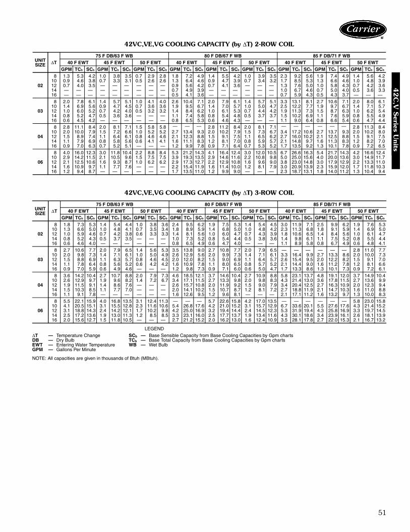
51
42VC,VE,VG COOLING CAPACITY (by ∆T) 2-ROW COIL
42VC,VE,VG COOLING CAPACITY (by ∆T) 3-ROW COIL
LEGEND
NOTE: All capacities are given in thousands of Btuh (MBtuh).
UNITSIZE ∆T
75 F DB/63 F WB 80 F DB/67 F WB 85 F DB/71 F WB40 F EWT 45 F EWT 50 F EWT 40 F EWT 45 F EWT 50 F EWT 40 F EWT 45 F EWT 50 F EWT
GPM TCb SCb GPM TCb SCb GPM TCb SCb GPM TCb SCb GPM TCb SCb GPM TCb SCb GPM TCb SCb GPM TCb SCb GPM TCb SCb
02
8 1.3 5.3 4.2 1.0 3.8 3.5 0.7 2.9 2.8 1.8 7.2 4.9 1.4 5.5 4.2 1.0 3.9 3.5 2.3 9.2 5.6 1.9 7.4 4.9 1.4 5.6 4.210 0.9 4.6 3.8 0.7 3.3 3.1 0.5 2.6 2.6 1.3 6.4 4.6 0.9 4.7 3.9 0.7 3.4 3.2 1.7 8.5 5.3 1.3 6.6 4.6 1.0 4.8 3.912 0.7 4.0 3.5 — — — — — — 0.9 5.6 4.2 0.7 4.1 3.6 — — — 1.3 7.6 5.0 1.0 5.8 4.3 0.7 4.2 3.614 — — — — — — — — — 0.7 4.9 3.9 — — — — — — 1.0 6.7 4.6 0.7 5.0 4.0 0.5 3.6 3.316 — — — — — — — — — 0.5 4.1 3.6 — — — — — — 0.7 5.9 4.3 0.5 4.3 3.7 — — —
03
8 2.0 7.8 6.1 1.4 5.7 5.1 1.0 4.1 4.0 2.6 10.4 7.1 2.0 7.9 6.1 1.4 5.7 5.1 3.3 13.1 8.1 2.7 10.6 7.1 2.0 8.0 6.110 1.4 6.9 5.6 0.9 4.7 4.5 0.7 3.6 3.6 1.9 9.5 6.7 1.4 7.0 5.7 1.0 5.0 4.7 2.5 12.2 7.7 1.9 9.7 6.7 1.4 7.1 5.712 1.0 6.0 5.2 0.7 4.2 4.0 0.5 3.2 3.2 1.4 8.4 6.2 1.0 6.1 5.3 0.7 4.4 4.2 1.9 11.3 7.3 1.5 8.7 6.3 1.0 6.2 5.414 0.8 5.2 4.7 0.5 3.6 3.6 — — — 1.1 7.4 5.8 0.8 5.4 4.8 0.5 3.7 3.7 1.5 10.2 6.9 1.1 7.6 5.9 0.8 5.5 4.916 0.6 4.5 4.2 — — — — — — 0.8 6.5 5.3 0.6 4.6 4.3 — — — 1.1 9.0 6.4 0.8 6.6 5.4 0.6 4.7 4.4
04
8 2.8 11.1 8.4 2.0 8.1 7.1 1.5 5.8 5.8 — — — 2.8 11.2 8.4 2.0 8.1 7.1 — — — — — — 2.8 11.3 8.410 2.0 10.0 7.9 1.5 7.2 6.6 1.0 5.2 5.2 2.7 13.4 9.3 2.0 10.2 7.9 1.5 7.3 6.7 3.4 17.2 10.6 2.7 13.7 9.3 2.0 10.2 8.012 1.5 8.9 7.4 1.1 6.4 6.1 0.8 4.6 4.6 2.1 12.3 8.8 1.5 9.1 7.5 1.1 6.5 6.2 2.7 16.0 10.2 2.1 12.5 8.8 1.5 9.1 7.514 1.1 7.9 6.9 0.8 5.8 5.6 0.6 4.1 4.1 1.6 11.1 8.3 1.2 8.1 7.0 0.8 5.9 5.7 2.1 14.8 9.7 1.6 11.3 8.3 1.2 8.2 7.016 0.9 7.0 6.3 0.7 5.2 5.1 — — — 1.2 9.9 7.8 0.9 7.1 6.4 0.7 5.3 5.2 1.7 13.5 9.2 1.3 10.1 7.8 0.9 7.2 6.5
06
8 4.0 16.0 12.3 3.0 11.8 10.4 2.2 8.8 8.4 5.3 21.2 14.3 4.1 16.4 12.4 3.0 12.0 10.5 6.7 26.6 16.3 5.4 21.7 14.3 4.2 16.6 12.410 2.9 14.2 11.5 2.1 10.5 9.6 1.5 7.5 7.5 3.9 19.3 13.5 2.9 14.6 11.6 2.2 10.8 9.8 5.0 25.0 15.6 4.0 20.0 13.6 3.0 14.9 11.712 2.1 12.5 10.6 1.6 9.3 8.7 1.0 6.2 6.2 2.9 17.3 12.7 2.2 12.9 10.8 1.6 9.6 9.0 3.8 23.0 14.8 3.0 17.9 12.9 2.2 13.3 11.014 1.6 10.9 9.7 1.1 7.7 7.6 — — — 2.2 15.4 11.9 1.6 11.4 10.0 1.2 8.1 7.9 3.0 20.9 13.9 2.3 15.9 12.0 1.7 11.8 10.316 1.2 9.4 8.7 — — — — — — 1.7 13.5 11.0 1.2 9.9 9.0 — — — 2.3 18.7 13.1 1.8 14.0 11.2 1.3 10.4 9.4
UNITSIZE ∆T
75 F DB/63 F WB 80 F DB/67 F WB 85 F DB/71 F WB40 F EWT 45 F EWT 50 F EWT 40 F EWT 45 F EWT 50 F EWT 40 F EWT 45 F EWT 50 F EWT
GPM TCb SCb GPM TCb SCb GPM TCb SCb GPM TCb SCb GPM TCb SCb GPM TCb SCb GPM TCb SCb GPM TCb SCb GPM TCb SCb
02
8 1.8 7.3 5.3 1.4 5.4 4.4 1.0 3.8 3.6 2.4 9.5 6.2 1.9 7.5 5.3 1.4 5.4 4.5 3.0 11.9 7.1 2.5 9.9 6.2 1.9 7.6 5.310 1.3 6.6 5.0 1.0 4.8 4.1 0.7 3.5 3.4 1.8 8.9 5.9 1.4 6.8 5.0 1.0 4.8 4.2 2.3 11.3 6.8 1.8 9.1 5.9 1.4 6.9 5.012 1.0 5.9 4.6 0.7 4.2 3.8 0.6 3.3 3.3 1.4 8.1 5.6 1.0 6.0 4.7 0.7 4.3 3.9 1.8 10.6 6.5 1.4 8.4 5.6 1.0 6.1 4.714 0.8 5.2 4.3 0.5 3.7 3.5 — — — 1.0 7.3 5.2 0.8 5.4 4.4 0.5 3.8 3.6 1.4 9.8 6.1 1.1 7.5 5.2 0.8 5.5 4.416 0.6 4.6 4.0 — — — — — — 0.8 6.5 4.9 0.6 4.7 4.0 — — — 1.1 8.9 5.8 0.8 6.7 4.9 0.6 4.8 4.1
03
8 2.7 10.6 7.7 2.0 7.9 6.5 1.4 5.6 5.3 3.5 13.8 9.0 2.7 10.8 7.7 2.0 7.9 6.5 — — — — — — 2.8 11.0 7.710 2.0 9.8 7.3 1.4 7.1 6.1 1.0 5.0 4.9 2.6 12.9 5.6 2.0 9.9 7.3 1.4 7.1 6.1 3.3 16.4 9.9 2.7 13.3 8.6 2.0 10.0 7.312 1.5 8.8 6.9 1.1 6.3 5.7 0.8 4.6 4.5 2.0 12.0 8.2 1.5 9.0 6.9 1.1 6.4 5.7 2.6 15.4 9.5 2.0 12.2 8.2 1.5 9.1 7.014 1.1 7.8 6.4 0.8 5.6 5.2 0.6 4.2 4.2 1.6 10.9 7.8 1.1 8.0 6.5 0.8 5.7 5.2 2.1 14.4 9.0 1.6 11.2 7.8 1.2 8.1 6.616 0.9 7.0 5.9 0.6 4.9 4.6 — — — 1.2 9.8 7.3 0.9 7.1 6.0 0.6 5.0 4.7 1.7 13.3 8.6 1.3 10.1 7.3 0.9 7.2 6.1
04
8 3.6 14.2 10.4 2.7 10.7 8.8 2.0 7.9 7.3 4.6 18.5 12.1 3.7 14.6 10.4 2.7 10.9 8.8 5.8 23.1 13.7 4.8 19.1 12.0 3.7 14.9 10.410 2.6 12.9 9.7 1.9 9.6 8.2 1.4 7.2 6.7 3.4 17.1 11.5 2.7 13.3 9.8 2.0 9.8 8.3 4.3 21.4 13.0 3.6 17.8 11.5 2.7 13.6 9.912 1.9 11.5 9.1 1.4 8.6 7.6 — — — 2.6 15.7 10.8 2.0 11.9 9.2 1.5 9.0 7.9 3.4 20.4 12.5 2.7 16.3 10.9 2.0 12.3 9.414 1.5 10.3 8.5 1.1 7.7 7.0 — — — 2.0 14.1 10.2 1.5 10.7 8.7 1.2 8.1 7.2 2.7 18.8 11.9 2.1 14.7 10.3 1.6 11.0 8.816 1.1 9.1 7.8 — — — — — — 1.6 12.6 9.5 1.2 9.6 8.1 — — — 2.1 17.1 11.2 1.6 13.2 9.7 1.3 10.0 8.3
06
8 5.5 22.1 15.9 4.0 16.8 13.5 3.1 12.4 11.3 — — — 5.7 22.6 15.8 4.2 17.0 13.5 — — — — — — 5.8 23.0 15.810 4.1 20.5 15.1 3.1 15.5 12.8 2.3 11.6 10.6 5.4 26.8 17.6 4.2 21.0 15.2 3.1 15.7 12.9 6.7 33.6 20.1 5.5 27.6 17.6 4.3 21.4 15.212 3.1 18.8 14.3 2.4 14.2 12.1 1.7 10.2 9.8 4.2 25.0 16.9 3.2 19.4 14.4 2.4 14.5 12.3 5.3 31.9 19.4 4.3 25.8 16.9 3.3 19.7 14.514 2.5 17.2 13.6 1.9 13.0 11.3 1.2 8.5 8.5 3.3 23.1 16.0 2.5 17.7 13.7 1.9 13.4 11.6 4.3 30.1 18.6 3.4 23.9 16.1 2.6 18.1 13.916 2.0 15.6 12.7 1.5 11.8 10.5 — — — 2.7 21.2 15.2 2.0 16.2 13.0 1.6 12.4 10.9 3.5 28.1 17.8 2.7 22.0 15.3 2.1 16.7 13.2
∆T — Temperature Change SCb — Base Sensible Capacity from Base Cooling Capacities by Gpm chartsDB — Dry Bulb TCb — Base Total Capacity from Base Cooling Capacities by Gpm chartsEWT — Entering Water Temperature WB — Wet BulbGPM — Gallons Per Minute
42
C,V
Series U
nits
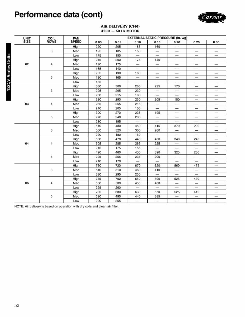
52
AIR DELIVERY (CFM)42CA — 60 Hz MOTOR
NOTE: Air delivery is based on operation with dry coils and clean air filter.
UNITSIZE
COILROWS
FANSPEED
EXTERNAL STATIC PRESSURE (in. wg)0.00 0.05 0.10 0.15 0.20 0.25 0.30
02
3High 220 205 185 160 — — —Med 195 185 150 — — — —Low 175 150 — — — — —
4High 215 200 175 140 — — —Med 190 175 — — — — —Low 165 140 — — — — —
5High 205 190 160 — — — —Med 180 165 — — — — —Low 155 — — — — — —
03
3High 330 300 265 225 170 — —Med 295 265 230 — — — —Low 250 215 180 — — — —
4High 320 290 250 205 150 — —Med 285 255 215 — — — —Low 240 205 105 — — — —
5High 300 270 235 195 — — —Med 270 240 200 — — — —Low 230 195 — — — — —
04
3High 510 480 450 415 370 290 —Med 360 320 300 260 — — —Low 220 180 160 — — — —
4High 500 470 440 400 340 240 —Med 305 285 265 225 — — —Low 215 175 155 — — — —
5High 490 460 430 390 325 230 —Med 295 255 235 200 — — —Low 210 170 — — — — —
06
3High 760 720 670 620 560 475 —Med 540 510 460 410 — — —Low 330 295 250 — — — —
4High 745 700 650 590 525 430 —Med 530 500 450 400 — — —Low 295 260 — — — — —
5High 725 680 630 570 525 410 —Med 520 490 440 385 — — —Low 290 255 — — — — —
Performance data (cont)42
C,V
Ser
ies
Uni
ts
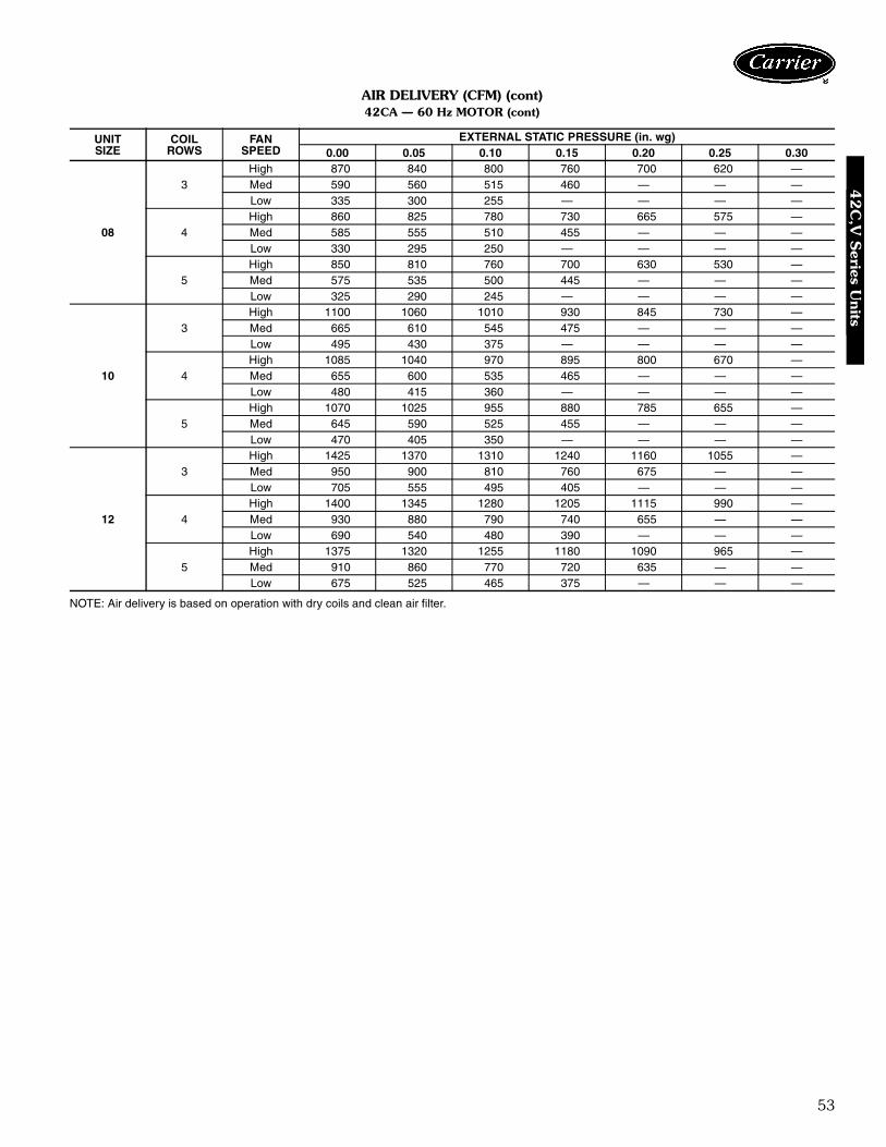
53
AIR DELIVERY (CFM) (cont)42CA — 60 Hz MOTOR (cont)
NOTE: Air delivery is based on operation with dry coils and clean air filter.
UNITSIZE
COILROWS
FANSPEED
EXTERNAL STATIC PRESSURE (in. wg)0.00 0.05 0.10 0.15 0.20 0.25 0.30
08
3High 870 840 800 760 700 620 —Med 590 560 515 460 — — —Low 335 300 255 — — — —
4High 860 825 780 730 665 575 —Med 585 555 510 455 — — —Low 330 295 250 — — — —
5High 850 810 760 700 630 530 —Med 575 535 500 445 — — —Low 325 290 245 — — — —
10
3High 1100 1060 1010 930 845 730 —Med 665 610 545 475 — — —Low 495 430 375 — — — —
4High 1085 1040 970 895 800 670 —Med 655 600 535 465 — — —Low 480 415 360 — — — —
5High 1070 1025 955 880 785 655 —Med 645 590 525 455 — — —Low 470 405 350 — — — —
12
3High 1425 1370 1310 1240 1160 1055 —Med 950 900 810 760 675 — —Low 705 555 495 405 — — —
4High 1400 1345 1280 1205 1115 990 —Med 930 880 790 740 655 — —Low 690 540 480 390 — — —
5High 1375 1320 1255 1180 1090 965 —Med 910 860 770 720 635 — —Low 675 525 465 375 — — —
42
C,V
Series U
nits
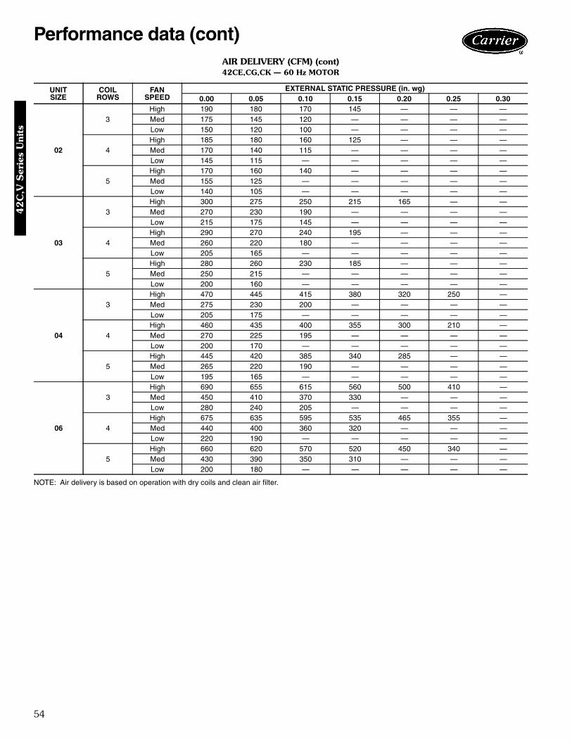
54
AIR DELIVERY (CFM) (cont)42CE,CG,CK — 60 Hz MOTOR
NOTE: Air delivery is based on operation with dry coils and clean air filter.
UNITSIZE
COILROWS
FANSPEED
EXTERNAL STATIC PRESSURE (in. wg)0.00 0.05 0.10 0.15 0.20 0.25 0.30
02
3High 190 180 170 145 — — —Med 175 145 120 — — — —Low 150 120 100 — — — —
4High 185 180 160 125 — — —Med 170 140 115 — — — —Low 145 115 — — — — —
5High 170 160 140 — — — —Med 155 125 — — — — —Low 140 105 — — — — —
03
3High 300 275 250 215 165 — —Med 270 230 190 — — — —Low 215 175 145 — — — —
4High 290 270 240 195 — — —Med 260 220 180 — — — —Low 205 165 — — — — —
5High 280 260 230 185 — — —Med 250 215 — — — — —Low 200 160 — — — — —
04
3High 470 445 415 380 320 250 —Med 275 230 200 — — — —Low 205 175 — — — — —
4High 460 435 400 355 300 210 —Med 270 225 195 — — — —Low 200 170 — — — — —
5High 445 420 385 340 285 — —Med 265 220 190 — — — —Low 195 165 — — — — —
06
3High 690 655 615 560 500 410 —Med 450 410 370 330 — — —Low 280 240 205 — — — —
4High 675 635 595 535 465 355 —Med 440 400 360 320 — — —Low 220 190 — — — — —
5High 660 620 570 520 450 340 —Med 430 390 350 310 — — —Low 200 180 — — — — —
Performance data (cont)42
C,V
Ser
ies
Uni
ts
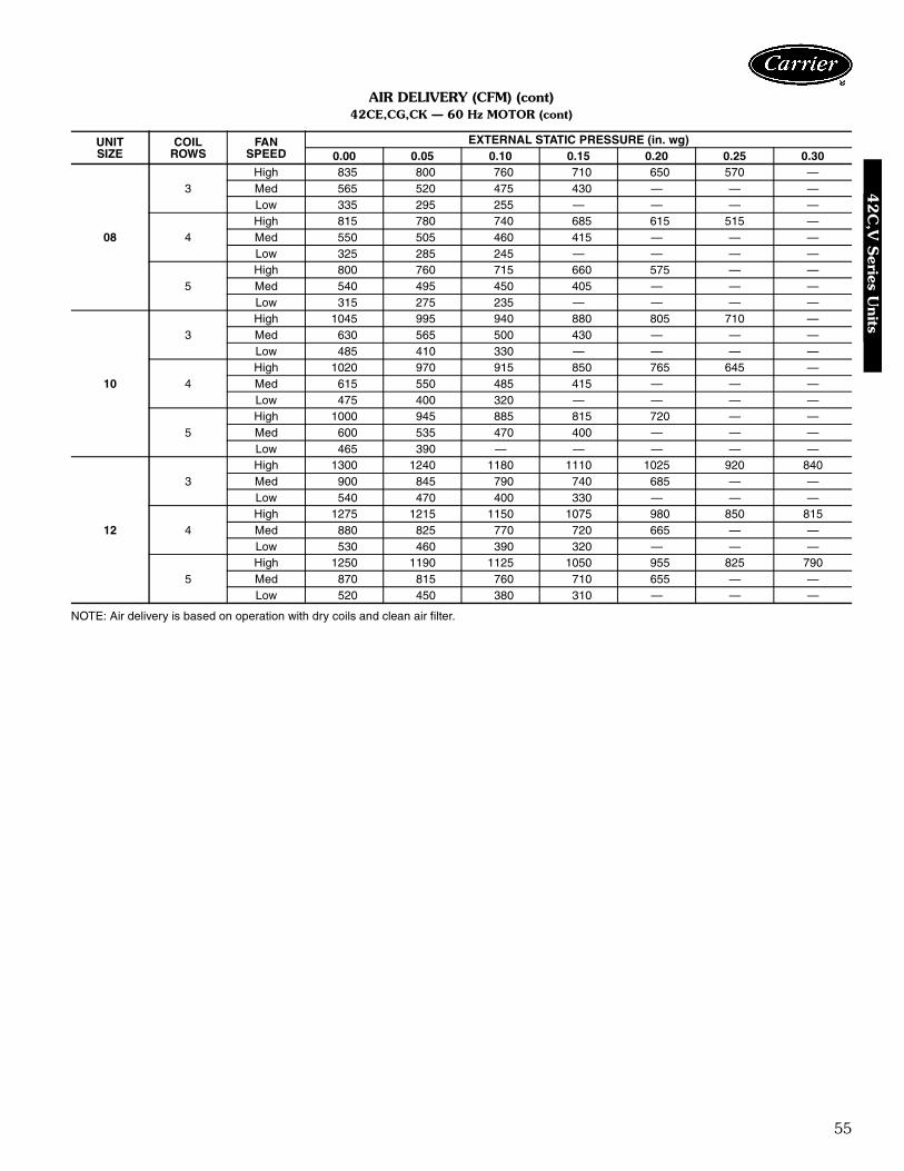
55
AIR DELIVERY (CFM) (cont)42CE,CG,CK — 60 Hz MOTOR (cont)
NOTE: Air delivery is based on operation with dry coils and clean air filter.
UNITSIZE
COILROWS
FANSPEED
EXTERNAL STATIC PRESSURE (in. wg)0.00 0.05 0.10 0.15 0.20 0.25 0.30
08
3High 835 800 760 710 650 570 —Med 565 520 475 430 — — —Low 335 295 255 — — — —
4High 815 780 740 685 615 515 —Med 550 505 460 415 — — —Low 325 285 245 — — — —
5High 800 760 715 660 575 — —Med 540 495 450 405 — — —Low 315 275 235 — — — —
10
3High 1045 995 940 880 805 710 —Med 630 565 500 430 — — —Low 485 410 330 — — — —
4High 1020 970 915 850 765 645 —Med 615 550 485 415 — — —Low 475 400 320 — — — —
5High 1000 945 885 815 720 — —Med 600 535 470 400 — — —Low 465 390 — — — — —
12
3High 1300 1240 1180 1110 1025 920 840Med 900 845 790 740 685 — —Low 540 470 400 330 — — —
4High 1275 1215 1150 1075 980 850 815Med 880 825 770 720 665 — —Low 530 460 390 320 — — —
5High 1250 1190 1125 1050 955 825 790Med 870 815 760 710 655 — —Low 520 450 380 310 — — —
42
C,V
Series U
nits

56
AIR DELIVERY (CFM) (cont)42CF — 60 Hz MOTOR
NOTE: Air delivery is based on operation with dry coils and clean air filter.
UNITSIZE
COILROWS
FANSPEED
EXTERNAL STATIC PRESSURE (in. wg)0.00 0.05 0.10 0.15 0.20 0.25 0.30
04
3High 530 540 505 465 420 360 285Med 535 505 470 420 365 — —Low 485 455 430 — — — —
4High 555 520 485 445 390 330 —Med 525 495 460 410 365 — —Low 420 390 360 — — — —
5High 540 510 470 425 365 290 —Med 515 485 450 400 — — —Low 400 370 340 — — — —
06
3High 720 680 635 585 530 460 385Med 640 600 555 505 450 380 —Low 540 500 455 405 — — —
4High 700 660 610 560 500 430 340Med 625 585 540 490 435 — —Low 525 485 440 390 — — —
5High 680 640 590 540 480 410 320Med 605 565 520 470 — — —Low 515 475 430 380 — — —
08
3High 800 750 695 640 580 515 440Med 660 610 555 500 440 375 —Low 545 495 430 385 225 — —
4High 780 725 670 615 555 485 395Med 645 590 535 480 425 350 —Low 535 485 420 375 — — —
5High 760 705 650 595 525 465 —Med 625 575 520 465 410 — —Low 525 475 410 365 — — —
10
3High 1295 1215 1130 1045 960 865 700Med 1195 1115 1030 945 860 — —Low 1060 980 900 820 — — —
4High 1260 1175 1090 1005 915 810 700Med 1165 1095 1010 925 — — —Low 1035 955 875 800 — — —
5High 1235 1150 1065 980 890 790 655Med 1145 1075 990 905 — — —Low 1015 935 855 — — — —
Performance data (cont)42
C,V
Ser
ies
Uni
ts

57
AIR DELIVERY (CFM) (cont)42VA,VB,VF — 60 Hz MOTOR
NOTE: Air delivery is based on operation with dry coils and clean air filter.
UNITSIZE
COILROWS
FANSPEED
EXTERNAL STATIC PRESSURE (in. wg)0.00 0.05 0.10 0.15 0.20 0.25 0.30
02
3High 240 195 150 105 — — —Med 210 165 120 — — — —Low 185 140 — — — — —
4High 215 170 135 95 — — —Med 190 145 — — — — —Low 165 120 — — — — —
5High 190 145 110 — — — —Med 180 130 — — — — —Low 160 115 — — — — —
03
3High 295 260 220 185 155 — —Med 250 215 175 — — — —Low 205 170 — — — — —
4High 285 245 205 170 140 — —Med 240 205 165 — — — —Low 200 165 — — — — —
5High 260 220 180 — — — —Med 230 195 — — — — —Low 195 160 — — — — —
04
3High 410 370 335 310 290 — —Med 295 255 220 — — — —Low 225 185 150 — — — —
4High 395 355 325 300 260 — —Med 280 245 210 — — — —Low 220 180 145 — — — —
5High 380 335 305 280 245 — —Med 270 235 210 — — — —Low 215 175 — — — — —
06
3High 620 565 515 475 440 — —Med 460 405 355 315 — — —Low 310 255 205 — — — —
4High 605 550 505 465 430 — —Med 450 395 345 305 — — —Low 305 250 200 — — — —
5High 590 535 485 440 410 — —Med 440 385 335 — — — —Low 300 245 — — — — —
42
C,V
Series U
nits

58
AIR DELIVERY (CFM) (cont)42VA,VB,VF — 60 Hz MOTOR (cont)
NOTE: Air delivery is based on operation with dry coils and clean air filter.
UNITSIZE
COILROWS
FANSPEED
EXTERNAL STATIC PRESSURE (in. wg)0.00 0.05 0.10 0.15 0.20 0.25 0.30
08
3High 700 640 600 545 500 — —Med 575 515 475 420 — — —Low 360 300 260 — — — —
4High 690 630 590 540 490 — —Med 570 510 470 415 — — —Low 350 290 250 — — — —
5High 680 620 580 530 480 — —Med 560 500 460 — — — —Low 340 280 — — — — —
10
3High 915 850 780 725 655 — —Med 675 650 580 530 — — —Low 490 445 395 345 — — —
4High 885 820 755 700 635 — —Med 650 625 555 — — — —Low 475 420 — — — — —
5High 860 790 720 640 560 — —Med 625 600 520 — — — —Low 465 410 — — — — —
12
3High 1100 1025 970 920 865 — —Med 935 860 805 755 700 — —Low 580 525 500 420 — — —
4High 1070 995 945 895 840 — —Med 910 835 780 730 655 — —Low 565 510 485 405 — — —
5High 1040 965 915 865 810 — —Med 890 820 765 715 640 — —Low 545 490 465 385 — — —
Performance data (cont)42
C,V
Ser
ies
Uni
ts
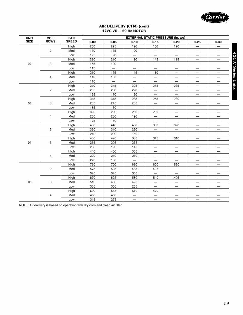
59
AIR DELIVERY (CFM) (cont)42VC,VE — 60 Hz MOTOR
NOTE: Air delivery is based on operation with dry coils and clean air filter.
UNITSIZE
COILROWS
FANSPEED
EXTERNAL STATIC PRESSURE (in. wg)0.00 0.05 0.10 0.15 0.20 0.25 0.30
02
2High 250 225 190 150 120 — —Med 170 135 100 — — — —Low 125 90 — — — — —
3High 230 210 180 145 115 — —Med 155 120 — — — — —Low 115 — — — — — —
4High 210 175 145 110 — — —Med 140 105 — — — — —Low 110 — — — — — —
03
2High 370 345 305 275 235 — —Med 285 260 220 — — — —Low 195 170 130 — — — —
3High 345 315 285 255 230 — —Med 265 245 205 — — — —Low 185 160 — — — — —
4High 320 290 260 230 — — —Med 250 230 190 — — — —Low 175 150 — — — — —
04
2High 480 440 400 360 320 — —Med 350 310 290 — — — —Low 240 200 150 — — — —
3High 460 420 385 345 310 — —Med 335 295 275 — — — —Low 230 190 140 — — — —
4High 440 400 365 — — — —Med 320 280 260 — — — —Low 220 180 — — — — —
06
2High 750 700 660 600 560 — —Med 575 525 485 425 — — —Low 395 345 305 — — — —
3High 670 625 580 540 495 — —Med 510 460 425 — — — —Low 355 305 265 — — — —
4High 600 555 510 470 — — —Med 450 400 — — — — —Low 315 275 — — — — —
42
C,V
Series U
nits
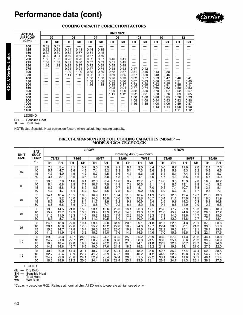
60
COOLING CAPACITY CORRECTION FACTORS
LEGEND
NOTE: Use Sensible Heat correction factors when calculating heating capacity.
DIRECT-EXPANSION (DX) COIL COOLING CAPACITIES (MBtuh)* —MODELS 42CA,CE,CF,CG,CK
LEGEND
*Capacity based on R-22. Ratings at nominal cfm. All DX units to operate at high speed only.
ACTUALAIRFLOW
(Cfm)
UNIT SIZE02 03 04 06 08 10 12
TH SH TH SH TH SH TH SH TH SH TH SH TH SH100 0.62 0.57 — — — — — — — — — — — —125 0.72 0.69 0.54 0.48 0.44 0.39 — — — — — — — —150 0.82 0.80 0.62 0.57 0.51 0.45 — — — — — — — —175 0.92 0.91 0.69 0.65 0.57 0.50 — — — — — — — —200 1.00 1.00 0.76 0.73 0.62 0.57 0.46 0.41 — — — — — —225 1.08 1.08 0.82 0.80 0.67 0.63 0.51 0.45 — — — — — —250 1.16 1.18 0.89 0.87 0.72 0.69 0.55 0.49 — — — — — —275 — — 0.95 0.94 0.77 0.74 0.58 0.53 0.47 0.42 — — — —300 — — 1.00 1.00 0.82 0.80 0.62 0.57 0.51 0.45 0.43 0.38 — —350 — — 1.11 1.12 0.92 0.91 0.69 0.65 0.57 0.50 0.48 0.46 — —400 — — — — 1.00 1.00 0.76 0.73 0.62 0.57 0.53 0.47 0.46 0.41450 — — — — 1.08 1.08 0.82 0.80 0.67 0.63 0.58 0.52 0.51 0.45500 — — — — 1.16 1.18 0.89 0.87 0.72 0.69 0.62 0.57 0.55 0.47550 — — — — — — 0.95 0.94 0.77 0.74 0.66 0.62 0.58 0.53600 — — — — — — 1.00 1.00 0.82 0.80 0.70 0.67 0.62 0.57700 — — — — — — 1.11 1.12 0.92 0.91 0.78 0.76 0.69 0.65800 — — — — — — — — 1.00 1.00 0.86 0.85 0.76 0.73900 — — — — — — — — 1.08 1.08 0.94 0.93 0.82 0.80
1000 — — — — — — — — 1.16 1.18 1.00 1.00 0.89 0.871200 — — — — — — — — — — 1.13 1.14 1.00 1.001400 — — — — — — — — — — — — 1.11 1.12
SH — Sensible HeatTH — Total Heat
UNITSIZE
SATSUCTTEMP
(F)
3 ROW 4 ROWEntering Air (F) — db/wb
76/63 78/65 80/67 82/69 76/63 78/65 80/67 82/69TH SH TH SH TH SH TH SH TH SH TH SH TH SH TH SH
02
35 7.3 5.4 8.1 5.7 9.0 5.9 9.9 6.1 9.0 6.4 10.0 6.7 11.0 7.0 12.1 7.340 5.7 4.7 6.6 4.9 7.4 5.2 8.3 5.4 7.3 5.6 8.3 5.9 9.3 6.2 10.3 6.545 4.3 4.0 4.9 4.2 5.7 4.5 6.6 4.7 5.6 4.8 6.4 5.1 7.4 5.4 8.5 5.750 3.1 3.1 3.6 3.5 4.1 3.8 4.5 4.0 4.1 4.0 4.7 4.3 5.5 4.6 6.4 4.9
03
35 10.5 7.8 11.6 8.1 12.8 8.4 14.0 8.7 12.7 9.1 14.0 9.5 15.3 9.8 16.6 10.240 8.4 6.8 9.5 7.1 10.7 7.5 11.9 7.8 10.5 8.1 11.8 8.5 13.1 8.8 14.5 9.245 6.3 5.8 7.3 6.2 8.5 6.5 9.7 6.8 8.1 7.0 9.3 7.4 10.7 7.8 12.1 8.150 4.7 4.7 5.4 5.2 6.2 5.6 7.2 5.9 6.0 6.0 6.9 6.3 8.1 6.7 9.4 7.1
04
35 14.1 10.4 15.5 10.8 16.9 11.1 18.4 11.5 16.4 11.9 17.9 12.3 19.4 12.7 21.0 13.040 11.6 9.2 13.0 9.6 14.5 10.0 16.0 10.4 13.8 10.7 15.4 11.1 17.0 11.5 18.6 11.945 8.9 8.0 10.2 8.4 11.7 8.9 13.2 9.3 10.9 9.4 12.5 9.8 14.2 10.3 15.8 10.850 6.6 6.6 7.6 7.2 8.8 7.7 10.2 8.1 8.2 8.0 9.4 8.5 11.0 9.0 12.7 9.5
06
35 19.0 14.5 21.0 15.0 23.1 15.6 25.3 16.1 23.3 17.1 25.6 17.7 27.9 18.3 30.3 18.940 15.2 12.7 17.3 13.3 19.4 13.9 21.6 14.5 19.3 15.2 21.6 15.9 24.0 16.6 26.5 17.245 11.6 11.0 13.3 11.6 15.2 12.2 17.4 12.8 15.0 13.3 17.1 14.0 19.6 14.7 22.1 15.350 8.7 8.7 9.9 9.8 11.2 10.5 13.0 11.1 10.9 10.9 12.8 12.0 14.8 12.7 17.1 13.4
08
35 24.6 18.8 27.0 19.4 29.4 20.0 31.9 20.6 29.1 21.8 31.7 22.5 34.3 23.1 37.0 23.640 20.1 16.8 22.6 17.5 25.2 18.2 27.8 18.9 24.6 19.7 27.4 20.5 30.1 21.2 33.0 21.845 15.6 14.7 17.8 15.4 20.3 16.2 23.0 16.9 19.6 17.4 22.2 18.3 25.1 19.1 28.1 19.850 11.9 11.9 13.4 13.2 15.3 14.0 17.6 14.8 14.6 14.6 17.0 15.9 19.5 16.8 22.4 17.6
10
35 29.9 23.3 32.7 24.0 35.6 24.7 38.5 25.3 35.2 26.9 38.3 27.6 41.3 28.2 44.4 28.840 24.7 21.0 27.7 21.8 30.7 22.6 33.8 23.3 30.0 24.5 33.3 25.4 36.6 26.2 39.9 26.945 19.3 18.4 22.0 19.3 24.9 20.2 28.1 21.0 24.1 21.8 27.3 22.8 30.7 23.7 34.3 24.650 14.8 14.8 16.7 16.6 19.0 17.6 21.8 18.6 18.2 18.2 21.1 19.9 24.1 21.0 27.5 22.0
12
35 40.3 30.0 44.4 31.1 48.7 32.2 53.1 33.3 48.2 35.0 52.7 36.2 57.4 37.4 62.2 38.540 32.7 26.4 36.9 27.7 41.2 28.9 45.7 30.0 40.2 31.2 44.9 32.6 49.8 33.9 54.7 35.145 24.9 22.9 28.6 24.1 32.9 25.4 37.4 26.6 31.5 27.2 36.1 28.7 41.0 30.1 46.1 31.450 18.6 18.6 21.2 20.6 24.4 21.9 28.4 23.1 23.5 23.1 26.9 24.7 31.3 26.1 36.3 27.5
db — Dry BulbSH — Sensible HeatTH — Total Heatwb — Wet Bulb
Performance data (cont)42
C,V
Ser
ies
Uni
ts

61
DIRECT-EXPANSION (DX) COIL COOLING CAPACITIES (MBtuh)* —MODELS 42VA,VB,VF
LEGEND
*Capacity based on R-22. Ratings at nominal cfm. All DX units to operate at high speed only.NOTE: DX coils are not available for 42VC,VE,VG units.
DIRECT EXPANSION (DX) COIL AIRFLOWCORRECTION FACTORS
NOTES:1. Consult factory for values outside of table.2. DX Total Capacity (MBtuh) =
Base TH x Total Correction FactorDX Sensible Capacity (MBtuh) =
Base SH x Sensible Correction Factor% of Nominal cfm =Actual cfm (from Air Delivery tables)
Nominal cfm
UNITSIZE
SATSUCTTEMP
(F)
3 ROW 4 ROWEntering Air (F) — db/wb
76/63 78/65 80/67 82/69 76/63 78/65 80/67 82/69TH SH TH SH TH SH TH SH TH SH TH SH TH SH TH SH
02
35 6.7 4.9 7.4 5.1 8.2 5.3 9.1 5.6 8.2 5.8 9.1 6.0 10.1 6.3 11.1 6.540 5.3 4.2 6.0 4.4 6.8 4.7 7.6 4.9 6.7 5.0 7.5 5.3 8.4 5.5 9.4 5.845 3.9 3.6 4.5 3.8 5.3 4.0 6.1 4.3 5.1 4.3 5.9 4.5 6.8 4.8 7.7 5.150 2.8 2.8 3.3 3.2 3.8 3.4 4.5 3.6 3.7 3.6 4.3 3.8 5.0 4.1 5.9 4.3
03
35 9.7 7.1 10.7 7.4 11.8 7.7 12.9 8.0 11.6 8.2 12.8 8.6 14.0 8.9 15.3 9.240 7.8 6.2 8.8 6.5 9.9 6.8 11.0 7.1 9.6 7.2 10.8 7.6 12.0 8.0 13.3 8.345 5.8 5.3 6.7 5.6 7.8 5.9 8.9 6.2 7.4 6.2 8.5 6.6 9.8 7.0 11.0 7.350 4.2 4.2 4.9 4.7 5.7 5.0 6.7 5.3 5.4 5.3 6.3 5.6 7.4 6.0 8.6 6.3
04
35 13.0 9.5 14.3 9.8 15.7 10.2 17.1 10.5 15.1 10.8 16.5 11.2 18.0 11.5 19.4 11.940 10.7 8.4 12.0 8.8 13.4 9.1 14.8 9.5 12.7 9.6 14.2 10.0 15.7 10.5 17.2 10.845 8.2 7.2 9.5 7.6 10.8 8.0 12.3 8.4 10.0 8.4 11.5 8.8 13.0 9.3 14.6 9.750 6.0 6.0 6.9 6.5 8.1 6.9 9.5 7.3 7.4 7.2 8.6 7.6 10.1 8.1 11.7 8.5
06
35 17.5 13.1 19.5 13.7 21.4 14.2 23.4 14.7 21.4 15.5 23.6 16.1 25.7 16.6 28.0 17.240 14.0 11.5 15.9 12.1 17.9 12.6 20.0 13.2 17.7 13.7 19.9 14.3 22.1 15.0 24.4 15.645 10.6 9.9 12.2 10.5 14.1 11.0 16.1 11.6 13.7 11.9 15.7 12.5 18.0 13.2 20.3 13.850 7.9 7.9 9.0 8.9 10.3 9.4 12.0 10.0 10.1 10.0 11.6 10.7 13.5 11.3 15.7 12.0
08
35 22.8 17.1 25.1 17.7 27.4 18.3 29.8 18.8 27.0 19.8 29.4 20.4 31.9 21.0 34.5 21.640 18.6 15.2 21.0 15.9 23.4 16.5 25.8 17.1 22.7 17.8 25.3 18.5 27.9 19.2 30.6 19.845 14.4 13.2 16.4 13.9 18.8 14.6 21.3 15.3 18.0 15.6 20.5 16.4 23.2 17.2 26.0 17.950 10.7 10.7 12.3 11.9 14.1 12.7 16.3 13.3 13.5 13.3 15.5 14.2 17.9 15.0 20.7 15.8
10
35 28.0 21.3 30.7 22.0 33.4 22.7 36.2 23.3 32.9 24.5 35.8 25.2 38.8 25.9 41.7 26.540 23.0 19.1 25.8 19.9 28.7 20.6 31.7 21.3 27.9 22.2 31.0 23.0 34.2 23.8 37.4 24.545 17.9 16.6 20.4 17.5 23.3 18.3 26.3 19.2 22.3 19.6 25.3 20.5 28.6 21.4 32.0 22.350 13.5 13.5 15.4 15.0 17.6 16.0 20.2 16.8 16.9 16.8 19.3 17.8 22.3 18.8 25.6 19.8
12
35 37.1 27.2 41.0 28.3 45.0 29.3 49.1 30.4 44.2 31.6 48.5 32.8 52.8 33.4 57.3 35.040 30.1 23.9 34.0 25.1 38.0 26.2 42.2 27.3 36.8 28.0 41.2 29.3 45.7 30.6 50.3 31.845 22.9 20.6 26.4 21.8 30.4 22.9 34.5 24.1 28.7 24.3 33.0 25.7 37.6 27.0 42.3 28.350 16.8 16.8 19.4 18.5 22.5 19.7 26.3 20.8 21.2 20.7 24.5 22.0 28.6 23.3 33.3 24.7
db — Dry BulbSH — Sensible HeatTH — Total Heatwb — Wet Bulb
% OFNOMINALAIRFLOW
(Cfm)
CORRECTION FACTOR
Total Sensible
80 0.95 0.9390 0.97 0.96
100 1.00 1.00110 1.02 1.04120 1.05 1.08
42
C,V
Series U
nits

62
HOT WATER HEATING CAPACITIES (MBtuh)* —MODELS 42CA,CE,CF,CG,CK,VA,VB,VF
NOTE: Ratings based on nominal cfm, 70 F edb, 180 F ewb.
HOT WATER HEATING CAPACITIES (MBtuh) —MODELS 42VC,VE
NOTE: Ratings based on nominal airflow (cfm), 70 F edb, 180 F ewb.
ROWS UNITSIZE
WATER FLOW (GPM)0.5 1.0 1.5 2.0 3.0 4.0 5.0 6.0 7.0 8.0 10.0 12.0
1
02 7.6 8.8 9.2 9.4 9.6 9.8 — — — — — —03 9.3 11.2 12.0 12.5 12.8 13.0 — — — — — —04 12.0 14.0 15.3 16.2 16.8 17.1 — — — — — —06 13.5 18.0 20.4 21.8 24.0 24.4 — — — — — —08 — 21.3 24.8 26.5 28.8 30.0 — — — — — —10 — 24.0 30.5 33.5 36.2 37.5 — — — — — —12 — 26.5 35.8 38.8 42.3 44.0 — — — — — —
2
02 12.1 14.1 15.0 15.7 16.4 16.8 — — — — — —03 16.6 19.4 20.6 21.8 23.0 23.5 — — — — — —04 18.5 23.4 25.5 26.7 28.6 29.4 — — — — — —06 — 29.0 33.0 34.8 37.2 38.8 39.8 40.5 41.1 42.0 — —08 — 32.8 37.7 40.8 45.0 46.9 47.5 49.7 50.6 51.4 — —10 — 40.5 47.5 51.4 56.5 59.5 61.5 63.5 65.0 66.0 — —12 — 49.0 55.5 59.5 64.7 68.0 70.7 72.7 74.0 75.3 — —
3
02 15.0 17.4 18.6 19.4 20.3 20.8 — — — — — —03 20.0 24.0 25.5 26.9 28.5 29.6 — — — — — —04 22.5 29.0 31.6 33.0 35.2 36.4 — — — — — —06 — — 40.5 43.0 46.0 47.8 49.0 50.0 50.6 51.1 — —08 — — 47.0 51.2 55.5 58.0 60.0 61.5 62.6 63.5 — —10 — — — 63.5 69.5 73.5 76.0 78.4 80.0 81.5 82.8 84.512 — — — 70.0 79.4 84.2 87.5 90.0 92.0 93.4 96.0 —
4
02 17.2 20.0 21.2 21.8 22.5 23.0 — — — — — —03 21.5 27.0 29.1 30.0 31.8 32.6 — — — — — —04 25.0 33.0 35.6 37.0 38.5 39.6 — — — — — —06 — — 46.0 50.0 53.5 55.0 56.0 57.0 57.8 58.7 — —08 — — 51.3 55.0 60.0 63.0 65.0 66.4 67.4 68.3 — —10 — — — 70.5 77.7 81.5 84.1 86.3 88.0 89.5 91.3 92.512 — — — 82.5 92.5 97.5 101.1 104.0 106.5 108.5 110.5 112.0
ROWS UNITSIZE
WATER FLOW (GPM)0.5 1.0 1.5 2.0 2.5 3.0 4.0
1
02 7.2 9.7 10.4 10.7 10.8 — —03 9.5 12.4 14.1 15.1 15.5 — —04 10.1 14.5 17.4 19.4 20.8 21.5 22.206 14.6 20.2 23.5 26.0 27.5 28.7 29.7
2
02 11.2 14.3 15.6 16.5 17.2 17.7 —03 14.3 19.1 21.8 23.4 24.3 24.6 —04 — 22.6 27.1 30.0 32.0 33.2 34.106 — 31.1 36.6 39.7 42.0 44.1 46.8
3
02 12.8 16.5 18.4 19.7 20.7 21.4 —03 18.0 22.8 25.9 27.7 28.8 29.4 —04 — 25.5 31.8 33.6 35.2 36.2 36.806 — 37.0 40.9 43.7 46.0 47.8 51.0
Performance data (cont)42
C,V
Ser
ies
Uni
ts
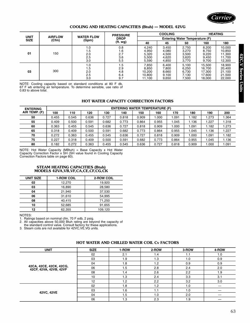
63
COOLING AND HEATING CAPACITIES (Btuh) — MODEL 42VG
NOTE: Cooling capacity based on standard conditions at 80 F db,67 F wb entering air temperature. To determine sensible, use ratio of0.83 to above total.
HOT WATER CAPACITY CORRECTION FACTORS
NOTE: Hot Water Capacity (MBtuh) = Base Capacity x Hot WaterCapacity Correction Factor x SH (SH value found in Cooling CapacityCorrection Factors table on page 60).
STEAM HEATING CAPACITIES (Btuh)MODELS 42VA,VB,VF,CA,CE,CF,CG,CK
NOTES:1. Ratings based on nominal cfm, 70 F edb, 2 psig.2. All capacities above 50,000 Btuh rating are beyond the capacity of
the standard control valve. Consult factory for these applications.3. Steam coils are not available for 42VC,VE,VG units.
HOT WATER AND CHILLED WATER COIL Cv FACTORS
UNITSIZE
AIRFLOW(Cfm)
WATER FLOW(Gpm)
PRESSUREDROP(ft. wg)
COOLING HEATINGEntering Water Temperature (F)
40 45 50 160 180
01 150
1.0 0.8 4,240 3,450 2,750 8,200 10,0001.5 1.6 4,950 4,080 3,270 8,750 10,8502.0 2.7 5,320 4,500 3,500 9,220 11,3002.5 3.6 5,500 4,620 3,620 9,450 11,7003.0 5.5 5,590 4,850 3,770 9,700 12,300
03 300
1.0 1.5 7,850 6,400 5,100 15,500 18,9001.5 2.9 8,850 7,800 6,250 16,700 20,4002.0 4.8 10,200 8,660 6,730 17,300 21,1002.5 6.4 10,800 9,100 7,130 17,600 21,5003.0 9.7 11,100 9,650 7,500 18,000 22,000
ENTERINGAIR TEMP. (F)
ENTERING WATER TEMPERATURE (F)100 110 120 130 140 150 160 170 180 190 200
50 0.455 0.545 0.636 0.727 0.818 0.909 1.000 1.091 1.182 1.273 1.36455 0.409 0.500 0.591 0.682 0.773 0.864 0.955 1.045 1.136 1.227 1.31860 0.363 0.455 0.545 0.636 0.727 0.818 0.909 1.000 1.091 1.182 1.27365 0.318 0.409 0.500 0.591 0.682 0.773 0.864 0.955 1.045 1.136 1.22770 0.272 0.363 0.455 0.545 0.636 0.727 0.818 0.909 1.000 1.091 1.18275 0.227 0.318 0.409 0.500 0.591 0.682 0.773 0.864 0.955 1.045 1.13680 0.182 0.272 0.363 0.455 0.545 0.636 0.727 0.818 0.909 1.000 1.091
UNIT SIZE 1-ROW COIL 2-ROW COIL02 12,270 19,92003 16,890 28,58004 21,940 37,53006 31,610 54,99508 40,415 71,25010 52,685 91,65512 62,355 109,120
UNIT SIZE 1-ROW 2-ROW 3-ROW 4-ROW
42CA, 42CE, 42CK, 42CG,42CF, 42VA, 42VB, 42VF
02 2.1 1.4 1.1 1.003 1.9 1.3 1.0 0.904 1.8 1.2 0.9 0.906 1.5 2.8 2.4 2.008 1.4 2.6 2.2 1.910 1.3 2.4 3.3 3.112 1.2 2.2 3.2 3.0
42VC, 42VE
02 1.8 1.2 1.0 —03 1.6 1.1 1.0 —04 1.5 1.0 2.0 —06 1.3 2.3 1.9 —
42
C,V
Series U
nits
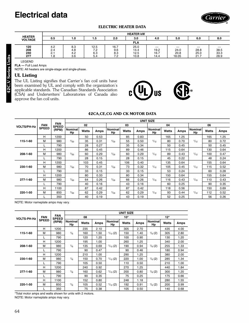
64
ELECTRIC HEATER DATA
LEGENDFLA — Full Load AmpsNOTE: All heaters are single-stage and single-phase.
UL ListingThe UL Listing signifies that Carrier’s fan coil units havebeen examined by UL and comply with the organization’sapplicable standards. The Canadian Standards Association(CSA) and Underwriters’ Laboratories of Canada alsoapprove the fan coil units.
42CA,CE,CG AND CK MOTOR DATA
NOTE: Motor nameplate amps may vary.
*Total motor amps and watts shown for units with 2 motors.NOTE: Motor nameplate amps may vary.
HEATERVOLTAGE
HEATER kW0.5 1.0 1.5 2.0 3.0 4.0 5.0 6.0 8.0
FLA120 4.2 8.3 12.5 16.7 25.0 — — — —208 2.4 4.8 7.2 9.6 14.4 19.2 24.0 28.8 38.5240 2.1 4.2 6.3 8.3 12.5 16.7 20.8 25.0 33.3277 1.8 3.6 5.4 7.2 10.8 14.4 18.05 21.7 28.9
VOLTS/PH-Hz FANSPEED
FANSPEED(RPM)
UNIT SIZE02 03 04 06
NominalHp Watts Amps Nominal
Hp Watts Amps NominalHp Watts Amps Nominal
Hp Watts Amps
115-1-60H 1200
1/30
50 0.531/30
85 0.831/12
165 1.251/12
165 1.25M 980 35 0.31 55 0.50 80 0.70 80 0.72L 790 28 0.27 35 0.34 50 0.45 50 0.45
208-1-60H 1200
1/30
86 0.451/30
89 0.461/12
115 0.641/12
130 0.64M 980 60 0.29 60 0.29 89 0.43 100 0.47L 790 28 0.15 28 0.15 45 0.22 48 0.24
230-1-60H 1200
1/30
103 0.451/30
106 0.401/12
135 0.641/12
155 0.64M 980 70 0.31 73 0.32 105 0.45 115 0.52L 790 33 0.15 33 0.15 53 0.24 60 0.28
277-1-60H 1200
1/30
80 0.331/30
80 0.341/15
150 0.641/15
155 0.64M 980 64 0.26 66 0.26 116 0.43 110 0.43L 790 40 0.16 43 0.16 60 0.25 90 0.35
220-1-50H 1100
1/30
87 0.421/30
87 0.421/12
118 0.561/12
150 0.69M 850 62 0.29 62 0.29 93 0.44 112 0.52L 350 40 0.19 43 0.19 52 0.25 56 0.26
VOLTS-PH-Hz FANSPEED
FANSPEED(RPM)
UNIT SIZE08 10* 12*
NominalHp Watts Amps Nominal
Hp Watts Amps NominalHp Watts Amps
115-1-60H 1200
1/6
235 2.101/12 (2)
305 2.701/6 (2)
435 4.00M 980 160 1.50 150 1.40 305 2.80L 790 120 1.20 100 0.90 130 1.20
208-1-60H 1200
1/6
195 1.001/12 (2)
260 1.251/6 (2)
340 2.00M 980 135 0.69 190 0.94 255 1.33L 790 90 0.47 90 0.46 180 0.94
230-1-60H 1200
1/6
210 1.001/12 (2)
290 1.251/6 (2)
380 2.00M 980 150 0.70 220 1.00 285 1.34L 790 105 0.50 110 0.50 210 1.00
277-1-60H 1200
1/8
240 0.921/15 (2)
270 1.251/8 (2)
440 1.84M 980 160 0.62 200 0.80 300 1.20L 790 90 0.35 75 0.25 175 0.66
220-1-50H 1100
1/6
152 0.801/12 (2)
248 1.181/6 (2)
280 1.55M 850 105 0.52 192 0.91 200 0.99L 350 75 0.38 105 0.50 140 0.68
Electrical data42
C,V
Ser
ies
Uni
ts

65
42CF MOTOR DATA
*Total motor amps and watts shown for units with 2 motors.NOTE: Motor nameplate amps may vary.
42VA,VB, AND VF MOTOR DATA
*Total motor amps and watts shown for units with 2 motors.NOTE: Motor nameplate amps may vary.
VOLTS-PH-Hz FANSPEED
FANSPEED(RPM)
UNIT SIZE04 06 08 10*
NominalHp Watts Amps Nominal
Hp Watts Amps NominalHp Watts Amps Nominal
Hp Watts Amps
115-1-60H 1200
1/8
150 1.401/8
180 0.831/8
225 1.701/8 (2)
300 2.80M 980 160 1.65 175 1.70 195 1.70 345 3.37L 790 135 1.45 140 1.65 165 1.45 290 2.95
208-1-60H 1200
1/8
135 0.681/8
150 1.451/8
160 0.741/8 (2)
280 1.44M 980 120 0.60 130 0.72 135 0.67 250 1.25L 790 105 0.54 110 0.66 110 0.57 205 1.05
230-1-60H 1200
1/8
150 0.681/8
160 0.571/8
170 0.751/8 (2)
300 1.44M 980 128 0.58 145 0.72 135 0.67 260 1.30L 790 115 0.55 127 0.66 127 0.57 205 1.05
277-1-60H 1200
1/8
145 0.601/8
155 0.601/8
170 0.661/8 (2)
310 1.20M 980 125 0.45 130 0.60 145 0.54 265 0.95L 790 90 0.36 90 0.48 100 0.39 195 0.74
220-1-50H 1200
1/6
205 1.001/6
225 0.361/6
256 1.201/6 (2)
420 2.00M 980 145 0.69 150 1.08 160 0.76 285 1.36L 790 93 0.45 95 0.47 95 0.48 180 0.88
VOLTS-PH-Hz FANSPEED
FANSPEED(RPM)
UNIT SIZE02 03 04 06
NominalHp Watts Amps Nominal
Hp Watts Amps NominalHp Watts Amps Nominal
Hp Watts Amps
115-1-60H 1200
1/30
50 0.531/30
80 0.831/12
130 1.251/6
180 2.00M 980 35 0.31 50 0.48 75 0.70 140 1.30L 790 28 0.27 35 0.33 50 0.47 60 0.57
208-1-60H 1200
1/30
85 0.451/30
85 0.461/12
110 0.641/6
190 1.00M 980 60 0.29 60 0.29 85 0.40 130 0.59L 790 28 0.14 28 0.14 45 0.22 90 0.47
230-1-60H 1200
1/30
100 0.451/30
102 0.461/12
120 0.641/6
205 1.00M 980 70 0.31 70 0.31 100 0.43 150 0.71L 790 33 0.15 33 0.15 53 0.24 105 0.50
277-1-60H 1200
1/30
80 0.331/30
82 0.341/15
140 0.631/6
205 0.92M 980 65 0.26 67 0.26 110 0.44 140 0.57L 790 40 0.16 43 0.17 65 0.25 80 0.34
220-1-50H 1200
1/30
80 0.401/30
85 0.401/12
145 0.701/6
175 0.91M 980 60 0.27 60 0.27 140 0.56 155 0.62L 790 30 0.15 30 0.15 120 0.38 130 0.43
VOLTS-PH-Hz FANSPEED
FANSPEED
UNIT SIZE08 10* 12*
NominalHp Watts Amps Nominal
Hp Watts Amps NominalHp Watts Amps
115-1-60H 1200
1/6
210 2.101/12 (2)
240 2.201/6 (2)
370 4.00M 980 140 1.30 145 1.30 265 2.50L 790 65 0.61 100 0.40 125 1.25
208-1-60H 1200
1/6
195 1.001/12 (2)
210 1.201/6 (2)
340 2.00M 980 135 0.69 160 0.80 220 1.15L 790 90 0.47 90 0.45 170 0.84
230-1-60H 1200
1/6
215 1.001/12 (2)
235 1.201/6 (2)
370 2.00M 980 155 0.71 190 0.85 285 1.40L 790 110 0.50 115 0.50 200 1.00
277-1-60H 1200
1/6
210 0.921/12 (2)
270 1.261/6 (2)
370 1.84M 980 140 0.58 200 0.82 255 1.10L 790 85 0.35 125 0.45 145 0.65
220-1-50H 1200
1/6
185 0.921/12 (2)
230 1.301/6 (2)
265 1.73M 980 160 0.63 190 1.02 190 1.00L 790 135 0.44 155 0.60 135 0.80
42
C,V
Series U
nits

66
42VC,VE MOTOR DATA
NOTE: Motor nameplate amps may vary.
42VG MOTOR DATA
*Total motor amps and watts shown for units with 2 motors.NOTE: Motor nameplate amps may vary.
VOLTS-PH-Hz FANSPEED
FANSPEED(RPM)
UNIT SIZE02 03 04
NominalHp Watts Amps Nominal
Hp Watts Amps NominalHp Watts Amps
115-1-60H 1200
1/20
68 0.341/12
135 1.351/12
150 1.45M 980 45 0.30 65 0.60 65 0.60L 790 25 0.20 40 0.30 40 0.30
208-1-60H 1200
1/2056 0.46
1/12109 0.56
1/12116 0.60
L 790 35 0.20 55 0.30 58 0.30
230-1-60H 1200
1/2064 0.50
1/12128 0.60
1/12138 0.64
L 790 42 0.22 65 0.28 67 0.30
277-1-60H 1200
1/20
85 0.351/12
135 0.581/12
140 0.58M 980 45 0.12 85 0.33 88 0.34L 790 35 0.07 55 0.22 57 0.22
VOLTS-PH-Hz FANSPEED
FANSPEED
UNIT SIZE06*
NominalHp Watts Amps
115-1-60H 1200
1/12 (2)260 2.70
M 980 125 1.20L 790 85 0.80
208-1-60H 1200
1/12 (2)205 1.00
L 790 103 0.50
230-1-60H 1200
1/12 (2)245 1.10
L 790 120 0.52
277-1-60H 1200
1/12 (2)260 1.16
M 980 155 0.65L 790 100 0.40
VOLTS-PH-Hz FANSPEED
FANSPEED(RPM)
UNIT SIZE01 03*
NominalHp Watts Amps Nominal
Hp Watts Amps
115-1-60H 1200
1/20
120 1.561/20 (2)
235 3.10M 980 75 0.92 145 1.80L 790 145 0.78 120 1.54
Electrical data (cont)42
C,V
Ser
ies
Uni
ts
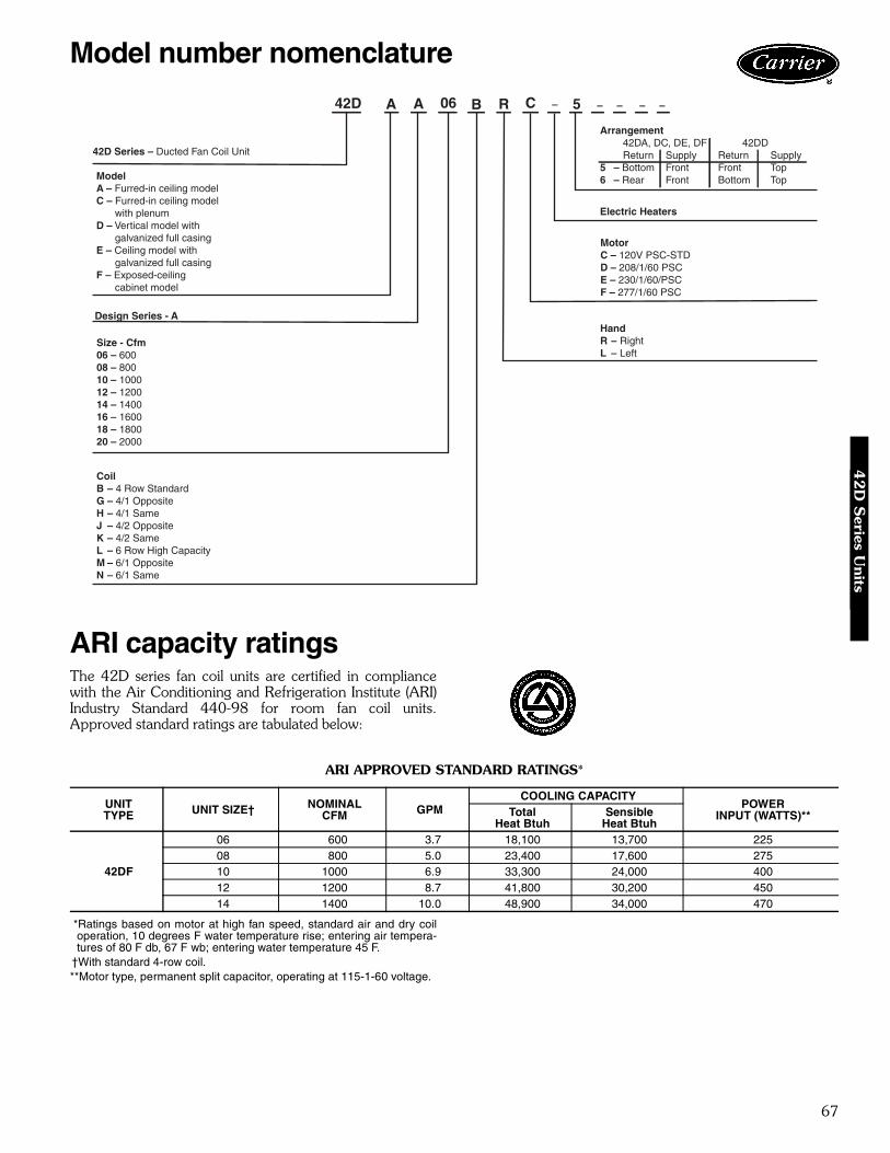
67
ARI capacity ratingsThe 42D series fan coil units are certified in compliancewith the Air Conditioning and Refrigeration Institute (ARI)Industry Standard 440-98 for room fan coil units.Approved standard ratings are tabulated below:
ARI APPROVED STANDARD RATINGS*
*Ratings based on motor at high fan speed, standard air and dry coiloperation, 10 degrees F water temperature rise; entering air tempera-tures of 80 F db, 67 F wb; entering water temperature 45 F.
†With standard 4-row coil.**Motor type, permanent split capacitor, operating at 115-1-60 voltage.
UNITTYPE UNIT SIZE† NOMINAL
CFM GPMCOOLING CAPACITY
POWERINPUT (WATTS)**Total
Heat BtuhSensible
Heat Btuh
42DF
06 600 3.7 18,100 13,700 22508 800 5.0 23,400 17,600 27510 1000 6.9 33,300 24,000 40012 1200 8.7 41,800 30,200 45014 1400 10.0 48,900 34,000 470
Model number nomenclature
ModelA – Furred-in ceiling modelC – Furred-in ceiling model
with plenumD – Vertical model with
galvanized full casingE – Ceiling model with
galvanized full casingF – Exposed-ceiling
cabinet model
Design Series - A
Size - Cfm06 – 60008 – 80010 – 100012 – 120014 – 140016 – 160018 – 180020 – 2000
CoilB – 4 Row StandardG – 4/1 OppositeH – 4/1 SameJ – 4/2 OppositeK – 4/2 SameL – 6 Row High CapacityM – 6/1 OppositeN – 6/1 Same
Arrangement42DA, DC, DE, DF 42DDReturn Supply Return Supply
5 – Bottom Front Front Top6 – Rear Front Bottom Top
MotorC – 120V PSC-STDD – 208/1/60 PSCE – 230/1/60/PSCF – 277/1/60 PSC
HandR – RightL – Left
42D A A 06 B R C – 5 – – – –
Electric Heaters
42D Series – Ducted Fan Coil Unit
42D
Series U
nits

68
SOUND POWER DATA42D SOUND RATINGS — OCTAVE BAND SOUND POWER LEVEL RATINGS* (dB)
*Testing per Proposed Standard Ducted Units, ARI Standard 260 (ANSI SI.32-1980). The sound data represents radiated sound power.
Physical data and dimensions
*Calculate Operating Weight of unit: Shipping Weight + Coil Water Weight x Number of Coil Rows.
SIZE NOMINALCFM SPEED RPM
CENTER FREQUENCY — Hz125 250 500 1000 2000 4000 8000
06 600High 820 71 68.5 57 55.5 46 42.5 34.5Medium 660 64.5 60.5 51.5 48.5 40.5 35.5 —Low 560 55 50.5 42 37 27 — —
08 800High 1000 68.5 66 58 56 46.5 41 30Medium 820 64.5 61.5 52 46 41 32 —Low 595 58 51.5 45.5 40 29 — —
10 1000High 1070 67.5 62.5 57 55 47 40 29.5Medium 875 61.5 57 51.5 46.5 39.5 31.5 —Low 690 52.5 49.5 44 39 29.5 18 —
12 1200High 890 68.5 66 57 50.5 44.5 39.5 29Medium 690 65 62.5 52 46.5 40 32.5 —Low 580 61 58.5 49.5 43 36 28 —
14 1400High 1000 69 66 58 54 46 40.5 29Medium 750 66 62 53.5 47.5 42 33 —Low 475 60 56.5 50 43 36.5 28 —
16 1600High 1100 70 65.5 59.5 57 48 43.5 34.5Medium 750 66 61 55.5 50 43.5 38 27.5Low 475 61 55 50 42.5 35.5 27 19
18 1800High 1060 70 65 60 57.5 49 44 34Medium 885 65.5 59.5 55 49.5 44 38.5 26Low 680 58 53 49 42 36 26.5 —
20 2000High 1030 71.5 64.5 60.5 58 51.5 47 37Medium 850 65 59 55 49.5 44.5 38.5 26Low 650 57.5 51.5 48.5 42 35 26 —
UNIT SIZE 42D 06 08 10 12 14 16 18 20NOMINAL AIRFLOW (cfm) 600 800 1000 1200 1400 1600 1800 2000SHIPPING WEIGHT (lb)*
42DA 64 79 93 110 119 129 137 15542DC 94 107 150 169 174 178 195 22042DD 150 163 176 195 220 235 240 24742DE 135 155 165 184 199 215 232 24342DF 157 167 177 199 215 229 249 258
COIL WATER WEIGHT(Approx lb per row of coil)
42D Series 1.3 1.6 1.9 2.3 2.7 3.0 3.4 3.7COILS
FPI 10 fins/inchCoil Face Area (sq. ft) 1.6 2.1 2.5 3.0 3.5 4.1 4.6 5.0
MOTOR (qty)42D Series 1 1 1 2 2 2 2 2
BLOWER (qty)42D Series 1 1 1 2 2 2 2 2
FILTERSNominal Size (in.) (1-in. thick)
42DA NA42DC 14 x 21 14 x 26 14 x 30 14 x 35 14 x 40 14 x 45 14 x 50 14 x 5442DD 13 x 21 13 x 26 13 x 30 13 x 35 13 x 40 13 x 45 13 x 50 13 x 5442DE 14 x 143/4 14 x 193/4 14 x 233/4 14 x 283/4 14 x 333/4 14 x 383/4 14 x 433/4 14 x 473/442DF 14 x 143/4 14 x 20 14 x 24 14 x 283/4 14 x 34 14 x 38 14 x 44 14 x 48Qty 1
SUPPLY DUCT COLLAR 1-in.PIPING CONNECTIONS(Sweat - 4-Row)
Inlet (in. OD) 5/8 7/8 11/8
Outlet (in. OD) 5/8 7/8 11/8
Sound data4
2D
Ser
ies
Uni
ts

69
Physical data and dimensions (cont)
42DA FURRED-IN CEILING MODEL
NOTES:1. R.H. unit shown; L.H. unit opposite. Coil connection locations are ± 5/8 inches.2. Sizes 06, 08 and 10 have one motor, one blower; sizes 12 through 20 have
2 motors, 2 blowers.3. Standard 4-row coil shown. Other coil option dimensional data available on request.4. See 42DA-203-1 for optional coil connections.5. Fan switch, wall plate not shown.6. Galvanized finish provided as standard.
UNITSIZE
NOMCFM
DIMENSIONS (in. ± 1/8)A B C D E
06 600 23 14 15 17 35/808 800 28 19 20 22 35/810 1000 32 23 24 26 35/812 1200 37 28 29 31 35/814 1400 42 33 34 36 31/16
16 1600 47 38 39 41 31/16
18 1800 52 43 44 46 31/16
20 2000 56 47 48 50 31/16
LEGEND1 — Motor-Blower Assembly2 — Motor Junction Box3 — Auxiliary Drip Lip (Optional, Shipped Loose)4 — Supply Duct Collar, 1 inch5 — Mounting Holes (four, 3/4-in. diameter) have
Rubber Grommets with 3/8-in. holes.6 — Return Connection7 — Supply Connection8 — Drain Connection, 7/8-in. OD9 — Air Vent, 1/8-in. MPT
42D
Series U
nits
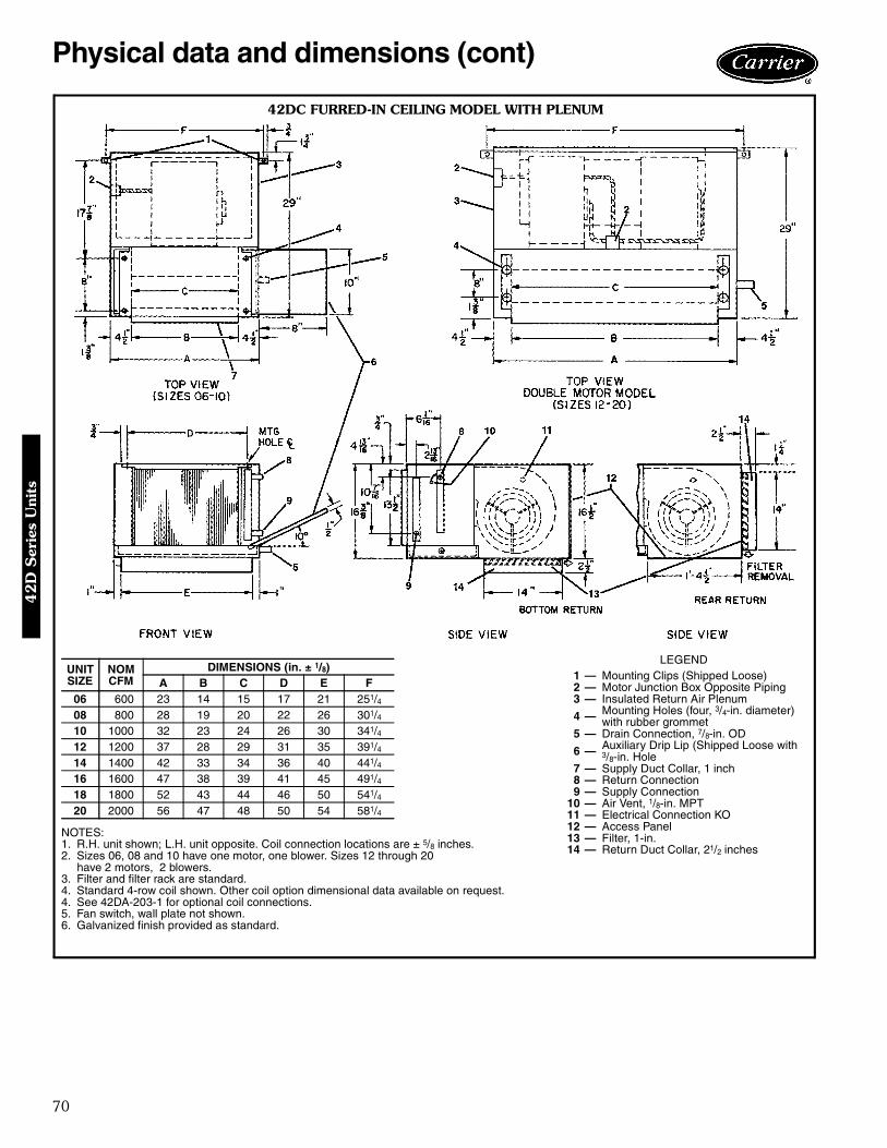
70
Physical data and dimensions (cont)
42DC FURRED-IN CEILING MODEL WITH PLENUM
NOTES:1. R.H. unit shown; L.H. unit opposite. Coil connection locations are ± 5/8 inches.2. Sizes 06, 08 and 10 have one motor, one blower. Sizes 12 through 20
have 2 motors, 2 blowers.3. Filter and filter rack are standard.4. Standard 4-row coil shown. Other coil option dimensional data available on request.4. See 42DA-203-1 for optional coil connections.5. Fan switch, wall plate not shown.6. Galvanized finish provided as standard.
UNITSIZE
NOMCFM
DIMENSIONS (in. ± 1/8)A B C D E F
06 600 23 14 15 17 21 251/408 800 28 19 20 22 26 301/410 1000 32 23 24 26 30 341/412 1200 37 28 29 31 35 391/414 1400 42 33 34 36 40 441/416 1600 47 38 39 41 45 491/418 1800 52 43 44 46 50 541/420 2000 56 47 48 50 54 581/4
LEGEND1 — Mounting Clips (Shipped Loose)2 — Motor Junction Box Opposite Piping3 — Insulated Return Air Plenum
4 — Mounting Holes (four, 3/4-in. diameter)with rubber grommet
5 — Drain Connection, 7/8-in. OD
6 — Auxiliary Drip Lip (Shipped Loose with3/8-in. Hole
7 — Supply Duct Collar, 1 inch8 — Return Connection9 — Supply Connection
10 — Air Vent, 1/8-in. MPT11 — Electrical Connection KO12 — Access Panel13 — Filter, 1-in.14 — Return Duct Collar, 21/2 inches
42D
Ser
ies
Uni
ts

71
42DD VERTICAL MODEL WITH FULL CASING
NOTES:1. R.H. unit shown; L.H. unit opposite. Coil connection locations are ± 5/8 inches.2. Standard 4-row coil shown. Other coil option dimensional data available on request.3. Sizes 06, 08 and 10 have one motor, one blower. Sizes 12 through 20 have
2 motors, 2 blowers.4. Supply and return connections terminate within unit when valves are factory
installed.5. See 42DD-203-1 for optional coil connections.6. Fan switch, wall plate not shown.7. Galvanized finish provided as standard.8. Units with internal factory valve packages have external connections located in tri-
angular section above coil.9. For bottom return (required for optional slide-in filter service from front) use dimen-
sion B minus 3 in.10. Consult Carrier for ducted front return air and external filter rack with 1-in. duct col-
lar and throwaway filters.11. Units with electric heat require additional access on the side of unit for servicing
contactor box.
UNITSIZE
NOMCFM
DIMENSIONS (in. ± 1/8)A B C D
06 600 23 21 15 611/16
08 800 28 26 20 611/16
10 1000 32 30 24 53/812 1200 37 35 29 53/814 1400 42 40 34 53/816 1600 47 45 39 53/818 1800 52 50 44 53/820 2000 56 54 48 53/8
LEGEND1 — Drain Connection, 7/8-in. OD2 — Return Air Opening3 — Supply Duct Connection, 1-in.4 — Front Access Panel5 — Filter, Throwaway6 — Optional 6-in. Legs7 — Supply Connection (See Table)8 — Return Connection (See Table)9 — Air Vent, 1/8-in. MPT
10 — Motor Junction Box
42D
Series U
nits
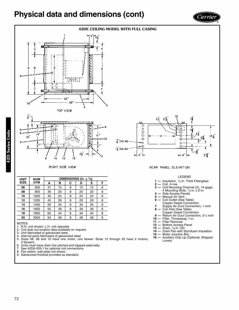
72
Physical data and dimensions (cont)
42DE CEILING MODEL WITH FULL CASING
NOTES:1. R.H. unit shown; L.H. unit opposite.2. Coil stub-out location data available on request.3. Unit fabricated of galvanized steel.4. Internal parts fabricated of galvanized steel.5. Sizes 06, 08 and 10 have one motor, one blower. Sizes 12 through 20 have 2 motors,
2 blowers.6. Units must have drain line pitched and trapped externally.7. See 42DA-203-1 for optional coil connections.8. Fan switch, wall plate not shown.9. Galvanized finished provided as standard.
UNITSIZE
NOMCFM
DIMENSIONS (in. ± 1/8)A B C D E F
06 600 31 15 8 15 15 808 800 36 20 8 20 20 810 1000 40 24 8 24 24 812 1200 45 29 8 29 29 814 1400 50 34 8 34 34 816 1600 55 39 8 39 39 818 1800 60 44 8 44 44 820 2000 64 48 8 48 48 8
LEGEND1 — Insulation, 1/2-in. Thick Fiberglass2 — Coil, 4-row3 — Unit Mounting Channel (2), 14-gage;
4 Mounting Slots, 1/2-in. x 2-in.4 — Side Access Panels5 — Manual Air Vent6 — Coil Outlet (See Table)
Copper Sweat Connection7 Supply Air Duct Connection, 1 inch8 — Coil Inlet (See Table),
Copper Sweat Connection9 — Return Air Duct Connection, 21/2 inch
10 — Filter, Throwaway, 1-in.11 — Filter Removal12 — Bottom Access Panel13 — Drain, 7/8-in. OD14 — Drain Pan with Styrofoam Insulation15 — Motor Junction Box16 — Auxiliary Drip Lip (Optional, Shipped
Loose)
42D
Ser
ies
Uni
ts
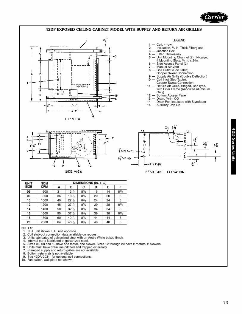
73
LEGEND1 — Coil, 4-row2 — Insulation, 1/2-in. Thick Fiberglass3 — Junction Box4 — Filter, Throwaway5 — Unit Mounting Channel (2), 14-gage;
4 Mounting Slots, 1/2 in. x 2-in.6 — Side Access Panel (2)7 — Manual Air Vent8 — Coil Outlet (See Table),
Copper Sweat Connection9 — Supply Air Grille (Double Deflection)
10 — Coil Inlet (See Table),Copper Sweat Connection
11 — Return Air Grille, Hinged, Bar Type,with Filter Frame (Anodized AluminumOnly)
12 — Bottom Access Panel13 — Drain, 7/8-in. OD14 — Drain Pan Insulated with Styrofoam15 — Auxiliary Drip Lip
42DF EXPOSED CEILING CABINET MODEL WITH SUPPLY AND RETURN AIR GRILLES
NOTES:1. R.H. unit shown; L.H. unit opposite.2. Coil stub-out connection data available on request.3. Units fabricated of galvanized steel with an Arctic White baked finish.4. Internal parts fabricated of galvanized steel.5. Sizes 06, 08 and 10 have one motor, one blower. Sizes 12 through 20 have 2 motors, 2 blowers.6. Units must have drain line pitched and trapped externally.7. Stamped supply and return grilles are not available.8. Bottom return air is not available.9. See 42DA-203-1 for optional coil connections.
10. Fan switch, wall plate not shown.
UNITSIZE
NOMCFM
DIMENSIONS (in. ± 1/8)A B C D E F
06 600 31 131/2 83/4 15 14 81/208 800 36 181/2 83/4 20 20 810 1000 40 221/2 83/4 24 24 812 1200 45 271/2 83/4 29 28 81/214 1400 50 321/2 83/4 34 34 816 1600 55 371/2 83/4 39 38 81/218 1800 60 421/2 83/4 44 44 820 2000 64 461/2 83/4 48 48 8
42D
Series U
nits

74
Accessory dimensions
A
G
C
F
RIG
HT
C
A
F
G
LEF
T
3,4,
6R
OW
CO
ILS
RIG
HT
LEF
T
A
G
CC
A
FG
B
D
FE
E
B
DA
LLS
PLI
TC
OIL
S
INLE
T
OU
TLE
T
ALL
DIM
EN
SIO
NS
±5/
8"
CO
ILC
ON
NE
CT
ION
SD
IME
NS
ION
S(i
n.)
3-R
ow
Co
il4-
Ro
wC
oil
6-R
ow
Co
ilA
CF
GA
CF
GA
CF
G37 /8
675 /1
675 /1
6
213/16
61 /16
413/16
107 /1
613 /4
71 /8413
/1610
7 /16
6413
/16913
/16
37 /8
6715
/16715
/16213
/1661 /1
657 /1
6913
/1613 /4
71 /857 /1
6913
/163
7 /86
57 /16
107 /1
6
Un
itC
fm
Rig
ht
Han
d
600-
800
600-
2000
1000
-200
060
0-80
060
0-20
0010
00-2
000
Lef
tH
and
CO
ILC
ON
NE
CT
ION
SD
IME
NS
ION
S(i
n.)
3an
d1
Sp
litC
oil
3an
d2
Sp
litC
oil
AB
CD
EF
GA
BC
DE
FG
213/16
37 /861 /1
611 /1
675 /1
675 /1
613
9 /16
21 /437 /8
61 /16
3 /475 /1
675 /1
613
1 /4213
/1637 /8
61 /16
11 /16
413/16
913/16
139 /1
621 /4
37 /861 /1
63 /4
413/16
913/16
131 /4
213/16
37 /861 /1
67 /1
6715
/16715
/1612
15/16
21 /437 /8
61 /16
3 /4715
/16715
/1613
1 /4213
/1637 /8
61 /16
7 /16
57 /16
107 /1
612
15/16
21 /437 /8
61 /16
3 /457 /1
610
7 /16
131 /4
Un
itC
fm
Rig
ht
Han
d60
0-80
010
00-2
000
600-
800
1000
-200
0L
eft
Han
d
CO
ILC
ON
NE
CT
ION
SD
IME
NS
ION
S(i
n.)
4an
d1
Sp
litC
oil
4an
d2
Sp
litC
oil
AB
CD
EF
GA
BC
DE
FG
13 /4213
/1661 /1
67 /1
6413
/1610
7 /16
1215/16
21 /437 /8
71 /83 /4
413/16
107 /1
613
1 /4
13 /4213
/1661 /1
611 /1
657 /1
6913
/1613
9 /16
21 /437 /8
71 /83 /4
57 /16
913/16
131 /4
Un
itC
fm
Rig
ht
Han
d60
0-20
00
600-
2000
Lef
tH
and
CO
ILC
ON
NE
CT
ION
S(i
n.)
AB
CD
EF
G
13 /427 /8
81 /43 /8
43 /410
3 /813
1 /4
13 /427 /8
81 /43 /8
43 /410
3 /813
1 /4
Un
itC
fm
Rig
ht
Han
d60
0-80
010
00-2
000
600-
800
1000
-200
0L
eft
Han
d
600
5 /85 /8
5 /87 /8
800
5 /85 /8
5 /87 /8
1000
5 /87 /8
7 /87 /8
1200
5 /87 /8
7 /87 /8
1400
5 /87 /8
11 /811 /8
1600
5 /87 /8
11 /811 /8
1800
5 /811 /8
11 /811 /8
2000
5 /811 /8
11 /811 /8
NO
TE
S:
1.S
eeP
hysi
calD
ata
for
pipi
ngkn
ocko
utlo
catio
nson
DE
and
DF
units
.2.
Coo
ling
coil
isfir
stin
the
air
stre
am.
NO
TE
:Doe
sno
tap
ply
whe
nop
tiona
lval
vepa
ckag
esar
eus
ed.
CO
ILC
ON
NE
CTI
ON
SS
IZE
S(O
.D.C
OP
PE
RS
WE
AT)(
in.)
Cfm
1-2
RO
W3
RO
W4
RO
W6
RO
W
37 /8
37 /8
6an
d1
Sp
litC
oil
42D
A,D
C,D
E A
ND
DF
OPTIO
NA
L C
OIL
CO
NN
EC
TIO
N L
OC
ATIO
N S
IZE 0
6 T
HR
U 2
0
42D
Ser
ies
Uni
ts

75
A
C
GF 3,
4,6
RO
WC
OIL
S
A
C
FG
3,4,
6R
OW
CO
ILS
A
C
FE ALL
SP
LIT
CO
ILS
GH
B
D
ALL
SP
LIT
CO
ILS
LEF
TR
IGH
TIN
LET
OU
TLE
TTO
LER
AN
CE
-5/
8"
DC
AB
EF
GH
CO
ILC
ON
NE
CT
ION
SD
IME
NS
ION
S(i
n.)
3-R
ow
Co
il4-
Ro
wC
oil
6-R
ow
Co
ilA
CF
GA
CF
GA
CF
G611
/1681 /2
2624
7 /841 /2
103 /1
623
3 /826
1 /231 /2
111 /8
2315/16
257 /8
53 /897 /8
2315/16
27
787 /8
251 /2
243 /8
43 /497 /8
2315/16
2515/16
37 /810
3 /424
1 /225
3 /853 /8
103 /1
623
3 /826
1 /2
Un
itC
fm
Rig
ht
Han
d60
0-80
060
0-20
0010
00-2
000
600-
800
600-
2000
1000
-200
0
Lef
tH
and
CO
ILC
ON
NE
CT
ION
SD
IME
NS
ION
S(i
n.)
AB
CD
EF
GH
AB
CD
EF
GH
53 /451 /4
75 /812
7 /16
1911
/1625
7 /16
245 /1
631
5 /16
53 /459 /1
675 /8
123 /4
201 /4
257 /1
624
5 /16
317 /8
47 /16
51 /4815
/1612
7 /16
1911
/1623
5 /16
267 /1
631
5 /16
47 /16
59 /16
815/16
123 /4
201 /4
235 /1
626
7 /16
317 /8
61 /8415
/16715
/1612
1 /820
3 /16
2415/16
233 /4
317 /1
661 /8
59 /16
715/16
123 /4
201 /4
2415/16
233 /4
317 /8
43 /4415
/1691 /4
121 /8
203 /1
622
13/16
2515/16
317 /1
643 /4
59 /16
91 /412
3 /420
1 /422
13/16
257 /8
317 /8
Un
itC
fm
Rig
ht
Han
d60
0-80
010
00-2
000
600-
800
1000
-200
0L
eft
Han
d
600
5 / 85 / 8
5 / 87 / 8
800
5 / 85 / 8
5 / 87 / 8
1000
5 / 87 / 8
7 / 87 / 8
1200
5 / 87 / 8
7 / 87 / 8
1400
5 / 87 / 8
11 / 811 / 8
1600
5 / 87 / 8
11 / 811 / 8
1800
5 / 811 / 8
11 / 811 / 8
2000
5 / 811 / 8
11 / 811 / 8
CO
ILC
ON
NE
CT
ION
SD
IME
NS
ION
S(i
n.)
AB
CD
EF
GH
AB
CD
EF
GH
47 /16
513/16
103 /1
613
1 /16
203 /4
233 /8
267 /1
632
7 /16
31 /259 /1
691 /4
123 /4
201 /4
2213/16
257 /8
317 /8
43 /463 /1
697 /8
133 /8
201 /4
237 /8
257 /8
317 /8
37 /859 /1
6815
/1612
3 /420
1 /423
5 /16
253 /8
317 /8
Un
itC
fm
Rig
ht
Han
d60
0-20
00
600-
2000
Lef
tH
and
NO
TE
S:
1.D
oes
not
appl
yw
hen
optio
nalv
alve
pack
ages
are
used
.2.
Coo
ling
coil
isfir
stin
the
airs
trea
m.
NO
TE
:Doe
sno
tap
ply
whe
nop
tiona
lval
vepa
ckag
esar
eus
ed.
CO
ILC
ON
NE
CTI
ON
SS
IZE
S(O
.D.C
OP
PE
RS
WE
AT)(
in.)
4A
nd
1S
plit
Co
il4
An
d2
Sp
litC
oil
3A
nd
1S
plit
Co
il3
An
d2
Sp
litC
oil
Cfm
1-2
RO
W3
RO
W4
RO
W6
RO
W
42D
D O
PTIO
NA
L C
OIL
CO
NN
EC
TIO
N L
OC
ATIO
N S
IZE 0
6 T
HR
U 2
0
42D
Series U
nits
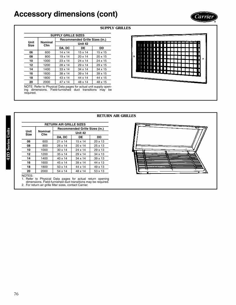
76
Accessory dimensions (cont)
SUPPLY GRILLES
NOTE: Refer to Physical Data pages for actual unit supply open-ing dimensions. Field-furnished duct transitions may berequired.
SUPPLY GRILLE SIZES
UnitSize
NominalCfm
Recommended Grille Sizes (in.)Unit 42
DA, DC DE DD06 600 14 x 14 15 x 14 15 x 1508 800 19 x 14 20 x 14 20 x 1510 1000 23 x 14 24 x 14 24 x 1512 1200 28 x 14 29 x 14 29 x 1514 1400 33 x 14 34 x 14 34 x 1516 1600 38 x 14 39 x 14 39 x 1518 1800 43 x 14 44 x 14 44 x 1520 2000 47 x 14 48 x 14 48 x 15
RETURN AIR GRILLES
NOTES:1. Refer to Physical Data pages for actual return opening
dimensions. Field-furnished duct transitions may be required.2. For return air grille filter sizes, contact Carrier.
RETURN AIR GRILLE SIZES
UnitSize
NominalCfm
Recommended Grille Sizes (in.)Unit 42
DA, DC DE DD06 600 21 x 14 15 x 14 20 x 1308 800 26 x 14 20 x 14 25 x 1310 1000 30 x 14 24 x 14 29 x 1312 1200 35 x 14 29 x 14 34 x 1314 1400 40 x 14 34 x 14 39 x 1316 1600 45 x 14 39 x 14 44 x 1318 1800 50 x 14 44 x 14 49 x 1320 2000 54 x 14 48 x 14 53 x 13
42D
Ser
ies
Uni
ts

77
42D COOLING CAPACITY (by GPM) 3-ROW COIL
42D COOLING CAPACITY (by GPM) 4-ROW COIL
See Legend on page 78.
UNITSIZE GPM
75 F DB/63 F WB 80 F DB/67 F WB 85 F DB/71 F WB40 F EWT 45 F EWT 50 F EWT 40 F EWT 45 F EWT 50 F EWT 40 F EWT 45 F EWT 50 F EWT
∆T TCb SCb ∆T TCb SCb ∆T TCb SCb ∆T TCb SCb ∆T TCb SCb ∆T TCb SCb ∆T TCb SCb ∆T TCb SCb ∆T TCb SCb
06
2 11.8 11.8 10.3 10.0 10.0 9.3 8.1 8.1 8.1 14.1 14.1 11.4 12.1 12.1 10.5 10.2 10.2 9.4 16.5 16.5 12.4 14.4 14.4 11.5 12.3 12.3 10.63 9.3 14.0 11.4 7.7 11.5 10.3 6.2 9.3 8.9 11.3 16.9 12.6 9.5 14.2 11.5 7.8 11.7 10.4 13.3 20.0 13.7 11.5 17.2 12.7 9.6 14.4 11.64 7.7 15.5 12.1 6.2 12.4 10.7 4.9 9.8 9.4 9.4 18.8 13.4 7.8 15.5 12.1 6.2 12.4 10.8 11.2 22.4 14.7 9.5 18.9 13.3 7.8 15.6 12.15 6.5 16.3 12.5 5.2 13.1 11.1 4.1 10.1 9.6 8.0 19.9 13.9 6.6 16.5 12.5 5.2 13.1 11.1 9.5 23.7 15.2 8.1 20.2 13.8 6.6 16.6 12.56 5.7 17.0 12.8 4.5 13.6 11.3 3.5 10.4 9.8 6.9 20.8 14.3 5.7 17.2 12.8 4.5 13.6 11.4 8.3 24.8 15.6 7.0 21.1 14.2 5.8 17.3 12.8
08
2 14.9 14.9 13.2 12.7 12.7 11.8 10.3 10.3 10.3 17.5 17.5 14.6 8.9 26.7 18.6 7.4 22.2 16.7 5.9 17.7 14.9 10.6 31.9 20.4 15.5 15.5 13.64 11.8 17.7 14.8 9.8 14.7 13.3 8.1 12.1 11.5 14.1 21.2 16.3 10.2 25.4 18.1 8.5 21.1 16.3 6.8 17.0 14.6 12.1 30.2 19.7 12.1 18.2 15.06 9.8 19.7 15.7 8.0 16.0 14.0 6.4 12.8 12.2 11.9 23.8 17.4 11.9 23.8 17.4 9.9 19.8 15.7 8.0 16.1 14.1 14.0 28.1 18.9 9.9 19.9 15.88 8.4 20.9 16.3 6.8 16.9 14.5 5.3 13.3 12.7 10.2 25.4 18.1 14.1 21.2 16.3 12.0 18.0 14.9 9.9 14.9 13.4 16.7 25.0 17.7 8.5 21.2 16.3
10 7.3 21.9 16.8 5.9 17.6 14.9 4.6 13.7 13.0 8.9 26.7 18.6 17.5 17.5 14.6 15.2 15.2 13.4 12.9 12.9 12.0 20.4 20.4 15.8 7.4 22.3 16.8
10
2 15.9 15.9 14.7 13.8 13.8 13.0 11.0 11.0 11.0 18.6 18.6 16.3 16.4 16.4 14.9 14.1 14.1 13.2 21.4 21.4 17.8 19.1 19.1 16.6 16.8 16.8 15.24 10.9 21.8 18.3 9.1 18.2 16.5 7.5 15.1 14.3 13.0 26.1 20.1 11.1 22.2 18.5 9.3 18.6 16.7 15.3 30.7 21.8 13.3 26.6 20.3 11.3 22.6 18.76 8.4 25.2 19.9 6.8 20.5 17.8 5.4 16.3 15.5 10.2 30.5 22.0 8.5 25.5 20.0 6.9 20.6 17.9 12.1 36.2 24.0 10.3 30.9 22.0 8.5 25.6 20.08 6.8 27.2 20.8 5.5 21.9 18.5 4.3 17.1 16.1 8.3 33.1 23.1 6.9 27.5 20.8 5.5 21.9 18.6 9.8 39.4 25.2 8.4 33.6 23.0 6.9 27.7 20.8
10 5.7 28.6 21.4 4.6 22.9 18.9 3.5 17.6 16.5 7.0 34.9 23.8 5.8 28.9 21.4 4.6 22.9 19.0 8.3 41.6 26.1 7.1 35.5 23.7 5.8 29.1 21.4
12
2 18.1 18.1 16.6 15.6 15.6 14.6 12.4 12.4 12.4 21.1 21.1 18.6 18.6 18.6 16.9 16.0 16.0 14.9 24.2 24.2 20.4 21.6 21.6 18.9 19.1 19.1 17.24 12.6 25.1 21.3 10.6 21.2 19.2 8.8 17.6 16.6 15.0 29.9 23.5 12.8 25.6 21.6 10.8 21.6 19.5 17.5 35.1 25.5 15.3 30.5 23.7 13.0 26.1 21.96 9.7 29.2 23.4 8.0 23.9 20.9 6.4 19.3 18.2 11.8 35.3 25.8 9.9 29.6 23.5 8.0 24.1 21.1 13.9 41.8 28.1 11.9 35.7 25.8 9.9 29.8 23.68 7.9 31.7 24.5 6.4 25.6 21.8 5.0 20.2 19.0 9.6 38.5 27.2 8.0 32.0 24.5 6.4 25.7 22.0 11.5 45.9 29.7 9.8 39.1 27.1 8.1 32.3 24.6
10 6.7 33.5 25.3 5.4 26.9 22.4 4.2 20.8 19.5 8.2 40.8 28.1 6.8 33.8 25.3 5.4 26.9 22.5 9.7 48.7 30.8 8.3 41.5 28.0 6.8 34.1 25.3
14
4 13.3 26.6 23.4 11.4 22.7 20.9 9.0 17.9 17.9 15.7 31.4 25.8 13.6 27.2 23.7 11.6 23.3 21.3 18.3 36.6 27.9 16.1 32.1 26.1 13.9 27.9 24.16 10.5 31.4 26.0 8.7 26.2 23.4 7.2 21.5 20.3 12.6 37.7 28.6 10.7 32.1 26.3 8.9 26.6 23.7 14.9 44.6 31.1 12.8 38.5 28.9 10.8 32.5 26.58 8.7 34.8 27.6 7.1 28.5 24.7 5.7 22.8 21.5 10.5 42.1 30.5 8.8 35.3 27.7 7.2 28.6 24.9 12.5 50.0 33.2 10.7 42.9 30.6 8.9 35.6 27.8
10 7.4 37.1 28.7 6.0 30.0 25.5 4.7 23.6 22.2 9.0 45.1 31.8 7.5 37.5 28.7 6.0 30.1 25.6 10.8 53.8 34.7 9.2 45.8 31.7 7.6 37.8 28.712 6.5 38.8 29.4 5.2 31.1 26.0 4.0 24.2 22.7 7.9 47.3 32.7 6.5 39.2 29.4 5.2 31.2 26.2 9.4 56.4 35.8 8.0 48.1 32.5 6.6 39.5 29.4
16
4 14.8 29.6 26.1 12.7 25.3 23.3 9.9 19.9 19.9 17.4 34.8 28.8 15.2 30.3 26.4 13.0 26.0 23.7 20.2 40.4 31.2 17.8 35.6 29.2 15.5 31.1 26.96 11.7 35.1 29.2 9.8 29.4 26.3 8.1 24.2 22.8 14.0 41.9 32.2 11.9 35.7 29.5 10.0 29.9 26.7 16.5 49.4 35.0 14.3 42.8 32.5 12.1 36.2 29.88 9.7 38.9 31.1 8.0 32.0 27.9 6.4 25.8 24.3 11.7 46.9 34.4 9.9 39.5 31.3 8.1 32.2 28.1 14.0 55.9 37.5 11.2 44.8 34.5 10.0 39.8 31.4
10 8.3 41.7 32.4 6.7 33.7 28.9 5.3 26.7 25.1 10.1 50.5 35.9 8.4 42.1 32.4 6.8 33.9 29.0 12.0 60.1 39.1 10.2 51.2 35.8 8.5 42.4 32.512 7.3 43.6 33.3 5.9 35.1 29.5 4.6 27.4 25.7 7.2 43.1 36.9 7.3 44.1 33.3 5.9 35.2 29.7 10.5 63.3 40.4 9.0 53.9 36.8 7.4 44.4 33.3
18
4 16.2 32.5 28.7 14.0 27.9 25.6 10.9 21.8 21.8 19.0 38.1 31.7 16.6 33.3 29.1 14.3 28.6 26.0 22.0 44.0 34.4 19.5 39.0 32.1 17.1 34.2 29.66 12.9 38.6 32.4 10.8 32.5 29.2 9.0 26.9 25.2 15.3 46.0 35.7 13.1 39.4 32.8 11.0 33.1 29.5 18.0 54.0 38.7 15.6 46.9 36.0 13.3 39.9 33.18 10.7 42.9 34.6 8.9 35.5 31.1 7.2 28.8 27.0 12.9 51.6 38.1 10.9 43.6 34.8 8.9 35.8 31.4 15.3 61.3 41.6 13.1 52.5 38.3 11.0 43.9 35.0
10 9.2 46.1 36.1 7.5 37.5 32.2 6.0 29.9 28.1 11.2 55.8 39.9 9.3 46.5 36.1 7.5 37.7 32.4 13.2 66.2 43.5 11.3 56.5 39.8 9.4 46.9 36.212 8.1 48.4 37.1 6.5 39.0 33.0 5.1 30.7 28.8 9.8 58.8 41.2 8.1 48.9 37.1 6.5 39.2 33.2 11.7 69.9 45.0 9.9 59.6 41.0 8.2 49.2 37.2
20
4 17.4 34.8 30.9 15.0 29.9 27.4 11.7 23.4 23.4 20.4 40.7 34.2 17.9 35.7 31.3 15.4 30.8 27.9 23.5 47.0 37.1 18.3 36.6 31.7 23.5 47.0 37.16 13.9 41.6 35.2 11.7 35.2 31.7 9.7 29.2 27.2 16.5 49.4 38.8 14.1 42.4 35.6 11.9 35.8 32.0 19.2 57.7 42.0 14.3 43.0 35.9 19.2 57.7 42.08 11.6 46.3 37.7 9.6 38.5 33.9 7.8 31.4 29.4 14.0 55.9 41.7 11.8 47.1 38.0 9.7 38.9 34.2 16.5 65.9 45.3 11.9 47.5 38.2 16.5 65.9 45.3
10 10.0 49.9 39.4 8.1 40.7 35.2 6.5 32.7 30.6 12.0 60.2 43.5 10.1 50.3 39.5 8.2 41.0 35.4 14.3 71.3 47.4 10.1 50.7 39.6 14.3 71.3 47.412 8.7 52.4 40.6 7.1 42.5 36.1 5.6 33.6 31.5 10.6 63.6 45.0 8.8 52.9 40.6 7.1 42.6 36.3 12.6 75.6 49.0 7.2 43.3 40.7 12.6 75.6 49.0
UNITSIZE GPM
75 F DB/63 F WB 80 F DB/67 F WB 85 F DB/71 F WB40 F EWT 45 F EWT 50 F EWT 40 F EWT 45 F EWT 50 F EWT 40 F EWT 45 F EWT 50 F EWT
∆T TCb SCb ∆T TCb SCb ∆T TCb SCb ∆T TCb SCb ∆T TCb SCb ∆T TCb SCb ∆T TCb SCb ∆T TCb SCb ∆T TCb SCb
06
4 8.2 16.3 13.1 6.8 13.6 11.8 5.5 11.1 10.4 9.8 19.7 14.4 8.3 16.7 13.2 8.3 16.7 13.2 11.6 23.2 15.7 10.1 20.1 14.5 8.5 17.1 13.46 6.3 18.8 14.2 5.1 15.4 12.7 4.0 12.1 11.1 7.6 22.9 15.8 6.4 19.2 14.3 6.4 19.2 14.3 9.1 27.2 17.3 7.8 23.5 15.8 6.5 19.6 14.48 5.1 20.4 14.9 4.1 16.3 13.1 3.1 12.6 11.4 6.2 24.9 16.6 5.2 20.6 14.9 5.2 20.6 14.9 7.4 29.7 18.3 6.3 25.3 16.5 5.2 20.9 14.8
10 4.2 21.2 15.3 3.4 17.0 13.4 2.6 12.9 11.6 5.2 25.9 17.1 4.3 21.5 15.2 4.3 21.5 15.2 6.2 30.9 18.8 5.3 26.5 17.0 4.4 21.8 15.212 3.6 21.8 15.6 2.9 17.5 13.7 2.2 13.2 11.8 4.4 26.7 17.4 3.7 22.2 15.5 3.7 22.2 15.5 5.3 31.9 19.2 4.6 27.4 17.3 3.8 22.6 15.5
08
4 10.5 20.9 17.0 8.8 17.6 15.4 7.3 14.6 13.5 12.5 25.0 18.7 10.7 21.4 17.2 9.0 18.0 15.7 14.7 29.4 20.3 12.8 25.6 18.9 10.9 21.9 17.46 8.1 24.3 18.6 6.7 20.0 16.7 5.3 16.0 14.7 9.8 29.4 20.6 8.3 24.8 18.7 6.8 20.3 16.8 11.6 34.9 22.5 10.1 30.2 20.6 8.4 25.3 18.88 6.6 26.4 19.6 5.3 21.4 17.3 4.2 16.6 15.1 8.0 32.2 21.8 6.7 26.8 19.5 5.4 21.5 17.4 9.6 38.4 23.9 8.2 32.8 21.6 6.8 27.1 19.5
10 5.5 27.7 20.2 4.5 22.3 17.8 3.4 17.1 15.4 6.8 33.8 22.5 5.6 28.1 20.1 4.5 22.4 17.8 8.1 40.3 24.7 6.9 34.5 22.3 5.7 28.5 20.012 4.8 28.6 20.6 3.8 23.0 18.1 2.9 17.5 15.6 5.8 35.0 23.0 4.9 29.1 20.5 3.9 23.1 18.1 7.0 41.8 25.3 6.0 35.8 22.8 4.9 29.5 20.4
10
4 12.4 24.8 20.6 10.5 21.1 18.6 8.8 17.6 16.3 14.7 29.5 22.6 12.7 25.4 20.8 10.8 21.6 18.9 17.2 34.5 24.4 15.1 30.2 22.8 13.0 26.0 21.16 9.7 29.0 22.6 8.0 24.0 20.3 6.5 19.4 17.9 11.6 34.9 24.9 9.9 29.6 22.7 8.1 24.4 20.5 13.8 41.3 27.1 11.9 35.7 25.0 10.0 30.1 22.88 7.9 31.7 23.8 6.4 25.8 21.2 5.1 20.3 18.6 9.6 38.5 26.4 8.0 32.2 23.8 6.5 26.0 21.3 11.4 45.7 28.9 9.8 39.1 26.3 8.1 32.5 23.8
10 6.7 33.4 24.6 5.4 27.0 21.7 4.2 20.9 19.0 8.1 40.6 27.4 6.8 33.9 24.5 5.4 27.1 21.8 9.7 48.4 30.0 8.3 41.4 27.2 6.9 34.3 24.512 5.8 34.6 25.2 4.6 27.9 22.2 3.6 21.4 19.3 7.0 42.2 28.0 5.9 35.2 25.1 4.7 28.1 22.2 8.4 50.3 30.8 7.2 43.1 27.8 5.9 35.6 25.0
12
4 14.4 28.7 24.0 12.3 24.6 21.8 10.3 20.7 18.9 17.0 33.9 26.4 12.3 24.6 21.8 14.7 29.4 24.3 19.7 39.5 28.5 17.4 34.7 26.6 15.1 30.2 24.76 11.2 33.7 26.5 9.4 28.1 23.9 7.7 23.0 21.1 13.5 40.4 29.2 9.4 28.1 23.9 11.5 34.4 26.9 15.9 47.6 31.8 13.8 41.3 29.3 11.6 34.9 26.98 9.3 37.0 28.1 7.6 30.3 25.1 6.0 24.1 22.0 11.2 44.7 31.1 7.6 30.3 25.1 9.4 37.6 28.1 13.2 53.0 33.9 11.4 45.5 31.0 9.5 37.9 28.1
10 7.8 39.2 29.1 6.4 31.8 25.8 5.0 24.8 22.5 9.5 47.6 32.3 6.4 31.8 25.8 7.9 39.7 29.0 11.3 56.5 35.3 9.7 48.4 32.1 8.0 40.2 29.012 6.8 40.8 29.8 5.5 32.9 26.3 4.2 25.4 22.9 8.3 49.6 33.2 5.5 32.9 26.3 6.9 41.4 29.7 9.9 59.1 36.4 8.4 50.6 33.0 7.0 41.9 29.6
14
3 16.6 24.9 22.5 13.3 19.9 19.9 11.1 16.7 16.7 19.3 29.0 25.2 17.2 25.8 23.0 13.6 20.4 20.4 22.2 33.2 27.5 20.0 30.0 25.7 17.8 26.8 23.57 10.7 37.3 30.0 8.9 31.3 27.1 7.4 25.9 23.8 12.7 44.6 33.0 10.9 38.2 30.3 9.1 32.0 27.5 15.0 52.5 35.8 13.1 45.7 33.3 11.1 39.0 30.7
11 7.9 43.6 33.0 6.5 35.7 29.4 5.1 28.3 25.8 9.6 52.8 36.5 8.1 44.4 33.0 6.6 36.1 29.6 11.4 62.7 39.9 9.8 53.9 36.5 8.2 45.0 33.115 6.3 47.2 34.6 5.1 38.1 30.6 3.9 29.5 26.6 7.7 57.4 38.5 6.4 47.9 34.5 5.1 38.3 30.6 9.1 68.5 42.2 7.8 58.6 38.3 6.5 48.5 34.419 5.2 49.3 35.6 4.2 39.6 31.3 3.2 30.3 27.1 6.3 60.2 39.7 5.3 50.1 35.4 4.2 39.9 31.3 7.6 71.9 43.7 6.5 61.6 39.5 5.4 50.8 35.3
16
3 18.3 27.4 24.8 14.6 21.9 21.9 12.2 18.2 18.2 21.3 32.0 27.8 19.0 28.5 25.4 14.9 22.3 22.3 24.4 36.7 30.5 22.1 33.2 28.4 19.7 29.6 25.97 11.9 41.7 33.8 10.1 35.3 30.6 8.4 29.3 26.9 14.2 49.7 37.2 12.2 42.7 34.2 10.3 36.1 31.1 16.7 58.3 40.3 14.6 50.9 37.5 12.5 43.7 34.6
11 8.9 48.9 37.3 7.3 40.2 33.3 5.9 32.2 29.3 10.8 59.2 41.3 9.1 49.8 37.4 7.4 40.7 33.6 12.8 70.2 45.0 11.0 60.3 41.2 9.2 50.6 37.515 7.1 53.2 39.2 5.7 43.0 34.7 4.5 33.5 30.3 8.6 64.7 43.6 7.2 54.0 39.1 5.8 43.3 34.8 10.3 77.0 47.8 8.8 65.9 43.3 7.3 54.6 39.119 5.9 55.8 40.4 4.7 44.9 35.6 3.6 34.5 30.9 7.2 68.0 45.1 6.0 56.7 40.3 4.8 45.2 35.6 8.5 81.2 49.5 7.3 69.5 44.8 6.0 57.4 40.1
18
3 19.9 29.9 27.0 15.8 23.7 23.7 19.9 29.9 27.0 23.2 34.8 30.2 20.7 31.1 27.6 16.1 24.2 24.2 26.6 39.9 33.3 24.1 36.1 30.9 21.5 32.3 28.27 13.2 46.1 37.6 11.2 39.1 34.0 13.2 46.1 37.6 15.6 54.7 41.2 13.5 47.2 38.0 11.5 40.1 34.5 18.3 63.9 44.7 16.0 56.0 41.6 13.8 48.3 38.4
11 9.9 54.2 41.5 8.1 44.6 37.2 9.9 54.2 41.5 11.9 65.4 45.9 10.0 55.1 41.6 8.2 45.3 37.5 14.1 77.4 50.0 12.1 66.5 45.8 10.2 56.0 41.815 7.9 59.1 43.8 6.4 48.0 38.8 7.9 59.1 43.8 9.6 71.7 48.7 8.0 60.0 43.7 6.4 48.3 38.9 11.4 85.3 53.2 9.7 73.1 48.4 8.1 60.6 43.619 6.5 62.1 45.2 5.3 50.1 39.8 6.5 62.1 45.2 8.0 75.7 50.4 6.6 63.1 45.0 5.3 50.4 39.9 9.5 90.2 55.3 8.1 77.3 50.0 6.7 63.9 44.9
20
3 21.2 31.8 28.7 16.7 25.1 25.1 13.9 20.9 20.9 24.7 37.0 32.3 22.0 33.0 29.4 17.1 25.6 25.6 28.3 42.4 35.5 25.6 38.4 32.9 22.9 34.4 30.07 14.2 49.8 40.9 12.1 42.5 37.1 10.2 35.7 32.4 16.8 58.8 44.9 14.6 51.0 41.4 12.5 43.6 37.6 19.6 68.6 48.6 17.2 60.3 45.3 14.9 52.3 41.9
11 10.7 58.7 45.4 8.8 48.6 40.7 7.2 39.5 35.9 12.8 70.7 50.1 10.8 59.6 45.5 9.0 49.4 41.1 15.2 83.4 54.5 13.0 71.8 50.0 11.0 60.7 45.815 8.6 64.3 48.0 7.0 52.3 42.6 5.5 41.2 37.3 10.4 77.9 53.2 8.7 65.2 47.9 7.0 52.7 42.7 12.3 92.5 58.1 10.6 79.2 52.9 8.8 65.9 47.819 7.1 67.7 49.6 5.8 54.7 43.7 4.5 42.5 38.1 8.7 82.4 55.2 7.2 68.8 79.4 5.8 55.1 43.8 10.3 98.1 60.5 8.8 84.0 54.8 7.3 69.6 49.3
Performance data4
2D
Series U
nits
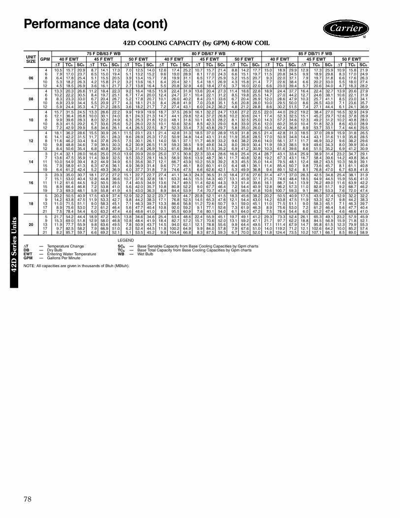
78
42D COOLING CAPACITY (by GPM) 6-ROW COIL
LEGEND
NOTE: All capacities are given in thousands of Btuh (MBtuh).
UNITSIZE GPM
75 F DB/63 F WB 80 F DB/67 F WB 85 F DB/71 F WB40 F EWT 45 F EWT 50 F EWT 40 F EWT 45 F EWT 50 F EWT 40 F EWT 45 F EWT 50 F EWT
∆T TCb SCb ∆T TCb SCb ∆T TCb SCb ∆T TCb SCb ∆T TCb SCb ∆T TCb SCb ∆T TCb SCb ∆T TCb SCb ∆T TCb SCb
06
4 10.5 15.7 20.9 8.7 14.1 17.3 7.0 12.5 14.0 12.6 17.4 25.2 10.7 15.7 21.4 8.8 14.2 17.7 15.0 18.9 29.9 12.9 17.3 25.9 10.9 15.8 21.96 7.9 17.0 23.7 6.5 15.0 19.4 5.1 13.2 15.2 9.6 19.0 28.9 8.1 17.0 24.3 6.6 15.1 19.7 11.5 20.8 34.5 9.9 18.9 29.8 8.3 17.0 24.98 6.4 17.8 25.4 5.1 15.5 20.5 3.9 13.4 15.7 7.8 19.9 31.1 6.5 17.7 25.9 5.2 15.5 20.7 9.3 22.0 37.1 7.9 19.7 31.8 6.6 17.6 26.3
10 5.3 18.2 26.3 4.2 15.8 21.2 3.2 13.6 16.1 6.4 20.4 32.1 5.4 18.1 26.9 4.3 15.8 21.4 7.7 22.6 38.4 6.6 20.2 33.0 5.5 18.0 27.412 4.5 18.5 26.9 3.6 16.1 21.7 2.7 13.8 16.4 5.5 20.8 32.9 4.6 18.4 27.6 3.7 16.0 22.0 6.6 23.0 39.4 5.7 20.6 34.0 4.7 18.3 28.2
08
4 13.3 20.3 26.6 11.2 18.4 22.3 9.2 16.4 18.5 15.9 22.4 31.9 13.6 20.4 27.3 11.4 18.6 22.8 18.9 24.4 37.7 16.4 22.4 32.7 13.9 20.6 27.96 10.2 22.2 30.5 8.4 19.7 25.1 6.7 17.4 20.0 12.4 24.7 37.1 10.4 22.1 31.2 8.5 19.8 25.5 14.7 27.0 44.2 12.7 24.6 38.1 10.6 22.1 31.98 8.3 23.3 33.0 6.7 20.4 26.7 5.2 17.8 20.7 10.1 26.0 40.2 8.4 23.1 33.6 6.7 20.4 26.9 12.0 28.6 47.9 10.3 25.7 41.1 8.5 23.0 34.1
10 6.9 23.9 34.4 5.5 20.9 27.7 4.3 18.1 21.3 8.4 26.8 41.9 7.0 23.8 35.1 5.6 20.8 28.0 10.0 29.5 50.0 8.6 26.5 43.0 7.1 23.6 35.712 5.9 24.4 35.3 4.7 21.2 28.5 3.6 18.2 21.7 7.2 27.4 43.1 6.0 24.2 36.2 4.8 21.2 28.8 8.6 30.2 51.5 7.4 27.1 44.4 6.1 24.1 36.9
10
4 15.7 31.5 24.5 13.3 26.6 22.2 9.9 19.9 19.9 18.7 37.5 26.9 16.1 32.2 24.7 13.6 27.2 22.5 22.0 44.0 29.2 19.2 38.4 27.0 16.5 32.9 24.96 12.1 36.4 26.8 10.0 30.1 24.0 8.1 24.3 21.3 14.7 44.1 29.8 12.4 37.2 26.8 10.2 30.6 24.1 17.4 52.3 32.5 15.1 45.2 29.7 12.6 37.8 26.98 9.9 39.6 28.3 8.0 32.2 24.9 6.3 25.3 21.8 12.0 48.1 31.6 10.1 40.3 28.2 8.1 32.5 25.0 14.3 57.2 34.6 12.3 49.2 31.2 10.2 40.8 28.0
10 8.3 41.5 29.2 6.7 33.6 25.6 5.2 26.0 22.3 10.1 50.6 32.6 8.5 42.3 29.0 6.8 33.9 25.6 12.0 60.2 35.9 10.4 51.8 32.3 8.6 43.0 28.912 7.2 42.9 29.9 5.8 34.6 26.1 4.4 26.5 22.5 8.7 52.3 33.4 7.3 43.8 29.7 5.8 35.0 26.0 10.4 62.4 36.8 8.9 53.7 33.1 7.4 44.6 29.5
12
4 18.1 36.2 28.6 15.5 30.9 26.1 11.5 23.1 23.1 21.4 42.8 31.3 18.5 37.0 28.9 15.9 31.8 26.5 21.4 42.8 31.3 18.5 37.0 28.9 15.9 31.8 26.56 14.1 42.2 31.5 11.7 35.1 28.3 9.6 28.9 25.3 17.0 50.9 34.8 14.4 43.1 31.6 11.9 35.8 28.5 17.0 50.9 34.8 14.4 43.1 31.6 11.9 35.8 28.58 11.6 46.2 33.4 9.4 37.8 29.5 7.5 30.1 26.1 14.0 56.1 37.1 11.7 46.9 33.2 9.6 38.2 29.6 14.0 56.1 37.1 11.7 46.9 33.2 9.6 38.2 29.6
10 9.8 48.8 34.6 7.9 39.5 30.3 6.2 30.9 26.5 11.9 59.3 38.5 9.9 49.6 34.3 8.0 39.9 30.4 11.9 59.3 38.5 9.9 49.6 34.3 8.0 39.9 30.412 8.4 50.6 35.4 6.8 40.8 30.9 5.3 31.6 26.9 10.3 61.6 39.6 8.6 51.5 35.2 6.9 41.2 30.9 10.3 61.6 39.6 8.6 51.5 35.2 6.9 41.2 30.9
14
3 21.4 32.1 28.0 16.6 25.0 25.0 13.9 20.9 20.9 25.0 37.5 30.8 22.3 33.4 28.6 16.9 25.4 25.4 28.7 43.1 33.4 25.9 38.9 31.4 23.2 34.7 29.17 13.6 47.5 35.9 11.4 39.9 32.5 9.5 33.2 29.1 16.3 56.9 39.6 13.9 48.7 36.1 11.7 40.8 32.8 19.2 67.3 43.1 16.7 58.4 39.6 14.2 49.8 36.4
11 10.0 54.9 39.4 8.2 44.9 34.9 6.5 35.6 30.7 12.1 66.7 43.9 10.2 55.9 39.2 8.3 45.5 35.0 14.4 79.5 48.1 12.4 68.2 43.5 10.3 56.9 39.115 7.9 58.9 41.3 6.3 47.6 36.1 4.9 36.9 31.4 9.6 71.7 46.1 8.0 60.1 41.0 6.4 48.1 36.1 11.4 85.4 50.7 9.8 73.6 45.7 8.1 61.1 40.819 6.4 61.2 42.4 5.2 49.3 36.9 4.0 37.7 31.8 7.9 74.6 47.5 6.6 62.6 42.1 5.3 49.9 36.8 9.4 89.1 52.4 8.1 76.8 47.0 6.7 63.8 41.8
16
3 23.3 35.0 30.7 18.1 27.2 27.2 15.1 22.7 22.7 27.4 41.1 34.3 24.3 36.5 31.3 18.4 27.6 27.6 31.4 47.1 37.0 28.3 42.5 34.8 25.4 38.1 31.97 15.1 53.0 40.4 12.8 44.8 36.6 10.7 37.6 32.8 18.1 63.3 44.5 15.5 54.3 40.7 13.1 45.9 37.1 21.3 74.6 48.4 18.5 64.9 44.5 15.9 55.6 41.0
11 11.2 61.6 44.5 9.2 50.5 39.5 7.4 40.5 34.9 13.6 74.7 49.5 11.4 62.6 44.3 9.3 51.4 39.6 16.1 88.7 54.1 13.9 76.2 49.0 11.6 63.9 42.215 8.9 66.4 46.8 7.2 53.8 41.0 5.6 42.0 35.7 10.8 80.8 52.2 9.0 67.7 46.4 7.2 54.4 40.9 12.8 96.2 57.3 11.0 82.8 51.7 9.2 68.7 46.219 7.3 69.3 48.1 5.9 55.8 41.9 4.5 43.0 36.3 8.9 84.4 53.9 7.4 70.7 47.8 5.9 56.5 41.8 10.6 100.7 59.3 9.1 86.7 53.3 7.6 72.0 47.4
18
5 20.2 50.5 40.9 17.5 43.9 37.4 12.9 32.2 32.2 23.7 59.3 44.7 20.8 52.1 41.5 18.3 45.6 38.2 20.2 50.5 40.9 17.5 43.9 37.4 12.9 32.2 32.29 14.2 63.8 47.5 11.9 53.3 42.7 9.8 44.2 38.3 17.1 76.8 52.5 14.5 65.3 47.6 12.1 54.4 43.0 14.2 63.8 47.5 11.9 53.3 42.7 9.8 44.2 38.3
13 11.0 71.5 51.1 9.0 58.3 45.1 7.1 46.3 39.7 13.3 86.6 56.8 11.2 72.6 50.7 9.1 59.0 45.1 11.0 71.5 51.1 9.0 58.3 45.1 7.1 46.3 39.717 8.9 75.6 53.0 7.2 61.2 46.4 5.6 47.7 40.4 10.8 92.0 59.2 9.1 77.1 52.6 7.3 61.9 46.3 8.9 75.6 53.0 7.2 61.2 46.4 5.6 47.7 40.421 7.5 78.4 54.4 6.0 63.2 47.4 4.6 48.6 41.0 9.1 95.5 60.9 7.6 80.1 54.0 6.1 64.0 47.2 7.5 78.4 54.4 6.0 63.2 47.4 4.6 48.6 41.0
20
5 21.7 54.2 44.4 18.9 47.2 40.5 13.8 34.6 34.6 25.4 63.4 48.6 22.4 55.9 45.1 19.7 49.1 41.2 29.3 73.3 52.4 26.1 65.3 49.1 23.2 57.9 45.99 15.3 69.0 51.8 12.9 58.0 46.8 10.8 48.4 41.9 18.4 82.7 57.2 15.7 70.6 52.0 13.1 59.2 47.1 21.7 97.7 62.2 18.8 84.5 56.9 15.9 71.8 52.1
13 11.9 77.7 55.9 9.8 63.6 49.5 7.8 50.9 43.7 14.5 94.0 62.1 12.1 78.8 55.6 9.9 64.4 49.5 17.1 111.4 67.9 14.7 95.8 61.5 12.3 79.9 55.317 9.7 82.5 58.2 7.9 66.9 51.0 6.2 52.4 44.5 11.8 100.2 64.9 9.9 84.0 57.8 7.9 67.6 51.0 14.0 119.2 71.2 12.1 102.6 64.2 10.0 85.2 57.421 8.2 85.7 59.7 6.6 69.2 52.1 5.1 53.5 45.2 9.9 104.4 66.8 8.3 87.5 59.3 6.7 70.0 52.0 11.8 124.4 73.5 10.2 107.1 66.1 8.5 89.0 58.9
∆T — Temperature Change SCb — Base Sensible Capacity from Base Cooling Capacities by Gpm chartsDB — Dry Bulb TCb — Base Total Capacity from Base Cooling Capacities by Gpm chartsEWT — Entering Water Temperature WB — Wet BulbGPM — Gallons Per Minute
Performance data (cont)4
2D
Ser
ies
Uni
ts
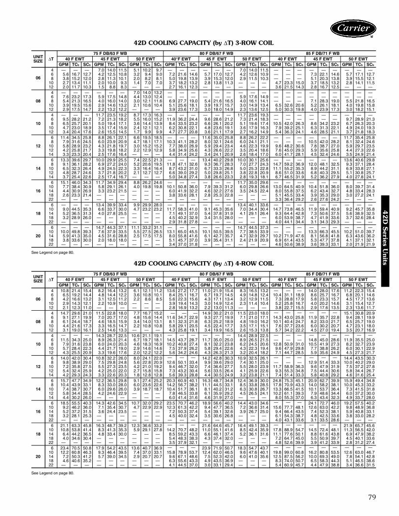
79
42D COOLING CAPACITY (by ∆T) 3-ROW COIL
See Legend on page 80.
42D COOLING CAPACITY (by ∆T) 4-ROW COIL
See Legend on page 80.
UNITSIZE ∆T
75 F DB/63 F WB 80 F DB/67 F WB 85 F DB/71 F WB40 F EWT 45 F EWT 50 F EWT 40°F EWT 45 F EWT 50 F EWT 40 F EWT 45 F EWT 50 F EWT
GPM TCb SCb GPM TCb SCb GPM TCb SCb GPM TCb SCb GPM TCb SCb GPM TCb SCb GPM TCb SCb GPM TCb SCb GPM TCb SCb
06
4 — — — 7.0 14.0 11.5 5.1 10.2 9.7 — — — — — — 7.0 14.0 11.5 — — — — — — — — —6 5.6 16.7 12.7 4.2 12.5 10.8 3.2 9.4 9.0 7.2 21.6 14.6 5.7 17.0 12.7 4.2 12.6 10.9 — — — 7.3 22.1 14.6 5.7 17.1 12.78 3.8 15.2 12.0 2.8 11.3 10.1 2.0 8.2 8.1 5.0 19.8 13.9 3.9 15.3 12.0 2.9 11.5 10.3 — — — 5.1 20.3 13.8 3.9 15.5 12.1
10 2.7 13.4 11.1 2.0 10.0 9.3 1.4 7.0 7.0 3.7 18.2 13.2 2.8 13.8 11.3 — — — 4.7 23.3 15.0 3.7 18.5 13.2 2.8 14.1 11.512 2.0 11.7 10.3 1.5 8.8 8.3 — — — 2.7 16.1 12.3 — — — — — — 3.6 21.5 14.3 2.8 16.7 12.5 — — —
08
4 — — — — — — 7.0 14.0 13.2 — — — — — — — — — — — — — — — — — —6 7.6 23.2 17.3 5.9 17.5 14.8 4.4 13.0 12.4 — — — — — — 5.9 17.6 14.9 — — — — — — — — —8 5.4 21.3 16.5 4.0 16.0 14.0 3.0 12.1 11.6 6.9 27.7 19.0 5.4 21.6 16.5 4.0 16.1 14.1 — — — 7.1 28.3 19.0 5.5 21.8 16.5
10 3.9 19.5 15.6 2.9 14.6 13.2 2.1 10.6 10.4 5.1 25.6 18.1 3.9 19.7 15.7 3.0 14.9 13.4 6.5 32.6 20.6 5.2 26.1 18.1 4.0 19.8 15.812 2.9 17.5 14.7 2.2 13.2 12.2 — — — 3.9 23.6 17.3 3.0 18.0 14.9 2.3 13.6 12.5 5.0 30.3 19.8 4.0 23.9 17.3 3.0 18.2 15.1
10
4 — — — 11.7 23.5 19.2 8.7 17.3 16.3 — — — — — — 11.7 23.6 19.3 — — — — — — — — —6 9.5 28.2 21.2 7.2 21.3 18.2 5.5 16.0 15.2 11.9 36.2 24.4 9.6 28.6 21.2 7.3 21.4 18.3 — — — — — — 9.7 28.9 21.38 6.5 25.7 20.1 5.0 19.4 17.1 3.6 14.4 13.9 8.4 33.5 23.2 6.6 26.1 20.2 5.1 19.6 17.4 10.5 42.0 26.3 8.6 34.2 23.2 6.7 26.3 20.3
10 4.7 23.0 18.9 3.5 17.4 15.9 2.4 12.1 12.1 6.2 30.8 22.1 4.8 23.6 19.1 3.6 17.9 16.3 7.9 39.2 25.1 6.3 31.3 22.1 4.9 24.0 19.312 3.4 20.4 17.6 2.6 15.5 14.5 1.7 9.9 9.9 4.7 27.7 20.8 3.6 21.1 17.9 2.7 16.2 14.9 5.4 36.3 24.1 4.6 28.5 21.1 3.7 21.8 18.3
12
6 11.4 34.5 25.8 8.8 26.1 22.1 6.6 19.5 18.5 — — — 11.6 35.0 25.8 8.8 26.2 22.2 — — — — — — 11.7 35.4 25.88 7.9 31.6 24.5 6.0 23.9 20.9 4.7 18.1 17.1 10.3 41.1 28.2 8.0 32.1 24.6 6.0 24.1 21.1 — — — 10.5 42.0 28.2 8.1 32.4 24.6
10 5.8 28.9 23.2 4.3 21.8 19.7 3.0 15.2 15.2 7.7 38.0 26.9 5.9 29.4 23.4 4.6 22.3 19.9 9.6 48.2 30.6 7.8 38.7 27.0 5.9 29.7 23.512 4.2 25.8 21.7 3.3 19.8 18.2 2.2 12.9 12.9 5.8 34.9 25.6 4.3 26.6 22.2 3.5 20.4 18.6 7.6 45.0 29.3 5.9 35.6 25.8 4.4 27.3 22.614 3.3 23.3 20.4 2.5 17.6 16.4 — — — 4.4 31.4 24.2 3.4 24.1 20.9 2.6 18.4 17.0 6.0 41.7 28.1 4.5 32.4 24.6 3.5 24.9 21.4
14
6 13.3 39.6 29.7 10.0 29.9 25.5 7.4 22.5 21.3 — — — 13.4 40.2 29.8 10.0 30.1 25.6 — — — — — — 13.6 40.6 29.88 9.1 36.1 28.2 6.9 27.2 24.0 5.2 20.6 19.5 11.8 47.1 32.6 9.3 36.7 28.3 7.0 27.7 24.3 14.7 59.2 36.9 12.0 48.1 32.5 9.3 37.1 28.4
10 6.5 32.3 26.4 4.9 24.5 22.3 3.3 16.4 16.4 8.7 43.2 31.0 6.7 33.3 26.8 5.0 25.3 22.8 11.1 55.2 35.3 8.9 44.2 31.1 6.9 33.8 27.112 4.8 28.7 24.6 3.7 21.8 20.2 2.1 12.7 12.7 6.6 39.0 29.2 5.0 29.8 25.1 3.8 22.8 20.9 8.6 51.0 33.6 6.8 40.3 29.5 5.1 30.8 25.714 3.7 25.4 22.6 2.5 17.4 16.7 — — — 5.0 34.8 27.4 3.8 26.6 23.3 2.8 19.3 18.1 6.7 46.5 31.9 5.2 36.2 27.9 4.0 27.8 24.1
16
6 15.1 46.0 34.3 11.7 34.9 29.4 8.8 26.2 24.6 — — — — — — 11.7 35.0 29.6 — — — — — — — — —10 7.7 38.4 30.9 5.8 29.1 26.1 4.0 19.8 19.8 10.1 50.8 36.0 7.9 39.3 31.2 6.0 29.8 26.6 13.0 64.5 40.9 10.4 51.8 36.0 8.0 39.7 31.414 4.4 30.9 26.9 3.3 23.2 21.5 — — — 6.0 41.9 32.2 4.6 32.2 27.6 3.5 24.5 22.4 8.0 55.8 37.5 6.2 43.4 32.7 4.8 33.4 28.318 2.6 23.3 21.4 — — — — — — 3.8 33.6 28.1 2.8 25.3 22.8 — — — 5.1 45.5 33.4 3.9 35.3 29.0 3.0 27.2 24.122 — — — — — — — — — — — — — — — — — — 3.3 36.4 29.2 2.6 27.6 24.2 — — —
18
6 — — — 13.4 39.9 33.4 9.9 29.9 28.0 — — — — — — 13.4 40.1 33.6 — — — — — — — — —10 9.0 44.5 35.3 6.6 33.7 30.0 4.7 23.2 23.2 11.7 58.3 41.0 9.1 45.3 35.6 7.0 34.4 30.4 14.7 73.8 46.5 11.9 59.4 40.9 9.2 45.7 35.814 5.2 36.5 31.3 4.0 27.8 25.5 — — — 7.1 49.1 37.0 5.4 37.8 31.9 4.1 29.1 26.4 9.3 64.4 42.8 7.3 50.6 37.5 5.6 38.9 32.518 3.2 28.9 26.0 — — — — — — 4.5 40.2 32.9 3.4 31.5 28.0 — — — 6.0 53.9 38.7 4.7 41.9 33.6 3.7 32.6 28.422 — — — — — — — — — 2.9 31.8 27.8 — — — — — — 4.0 44.1 34.4 3.1 34.3 29.3 — — —
20
6 — — — 14.7 44.3 37.1 11.1 33.2 31.1 — — — — — — 14.7 44.5 37.3 — — — — — — — — —10 10.0 49.8 39.3 7.6 37.9 33.5 5.5 27.5 26.5 13.1 65.0 45.5 10.1 50.5 39.5 7.7 38.5 33.9 — — — 13.3 66.3 45.5 10.2 51.0 39.714 5.9 41.3 35.0 4.5 31.6 28.8 2.5 17.5 17.5 8.0 55.8 41.6 6.1 42.7 35.7 4.7 32.9 29.7 10.2 71.9 47.6 8.1 56.8 41.8 6.3 43.6 36.218 3.8 33.6 30.0 2.0 18.0 18.0 — — — 5.1 45.7 37.0 3.9 35.4 31.1 2.4 21.9 20.9 6.9 61.4 43.5 5.3 47.7 37.8 4.1 37.1 32.122 — — — — — — — — — 3.4 37.0 31.8 — — — — — — 4.6 50.6 38.9 3.6 39.3 33.1 2.0 21.9 21.9
UNITSIZE ∆T
75 F DB/63 F WB 80 F DB/67 F WB 85 F DB/71 F WB40 F EWT 45 F EWT 50 F EWT 40 F EWT 45 F EWT 50 F EWT 40 F EWT 45 F EWT 50 F EWT
GPM TCb SCb GPM TCb SCb GPM TCb SCb GPM TCb SCb GPM TCb SCb GPM TCb SCb GPM TCb SCb GPM TCb SCb GPM TCb SCb
06
4 10.8 21.4 15.4 8.2 16.4 13.2 6.1 12.1 11.2 13.6 27.2 17.7 11.0 21.9 15.4 8.3 16.5 13.2 — — — 14.0 28.0 17.6 11.2 22.3 15.46 6.5 19.2 14.4 4.8 14.4 12.2 3.6 10.8 10.1 8.4 25.1 16.7 6.7 19.7 14.5 4.9 14.8 12.4 10.4 31.1 18.9 8.6 25.7 16.7 6.8 20.1 14.68 4.2 16.6 13.2 3.1 12.5 11.2 2.2 8.6 8.5 5.6 22.3 15.6 4.3 17.1 13.4 3.2 12.9 11.5 7.3 28.8 17.9 5.8 23.3 15.7 4.5 17.7 13.6
10 2.9 14.3 12.1 2.2 10.9 10.0 — — — 3.9 19.4 14.3 3.0 14.9 12.4 2.3 11.4 10.4 5.2 25.8 16.7 4.0 20.2 14.6 3.1 15.4 12.712 2.1 12.3 11.0 — — — — — — 2.8 16.9 13.2 2.2 13.0 11.3 — — — 3.8 22.7 15.5 2.9 17.6 13.5 2.3 13.6 11.7
08
4 14.7 29.6 21.0 11.5 22.8 18.0 7.7 16.7 15.2 — — — 14.9 30.2 21.0 11.5 23.0 18.0 — — — — — — 15.1 30.8 20.96 9.1 27.1 19.9 7.0 20.7 17.0 4.8 15.6 14.4 11.6 34.7 22.9 9.3 27.7 19.9 7.1 21.0 17.1 14.3 43.0 25.8 11.9 35.7 22.8 9.4 28.1 19.98 6.1 24.4 18.7 4.6 18.5 15.9 3.4 14.0 13.1 8.1 32.3 21.8 6.3 25.2 18.9 4.8 19.0 16.2 10.1 40.4 24.7 8.2 33.0 21.7 6.5 25.7 19.0
10 4.4 21.6 17.3 3.3 16.5 14.7 2.2 10.8 10.8 5.8 29.1 20.5 4.5 22.4 17.7 3.5 17.1 15.1 7.6 37.7 23.6 6.0 30.2 20.7 4.7 23.1 18.012 3.1 19.0 16.1 2.5 14.6 13.3 — — — 4.3 25.8 19.1 3.4 19.9 16.5 2.6 15.3 13.8 5.7 34.2 22.2 4.5 27.0 19.4 3.5 20.7 16.9
10
4 — — — 14.3 28.7 22.5 10.6 21.1 19.1 — — — — — — 14.4 28.9 22.5 — — — — — — — — —6 11.5 34.3 25.0 8.9 26.3 21.4 6.7 19.7 18.1 14.5 43.7 28.7 11.7 35.0 25.0 8.9 26.5 21.5 — — — 14.8 45.0 28.6 11.9 35.5 25.08 7.9 31.6 23.8 6.0 24.0 20.3 4.6 18.3 16.9 10.2 40.8 27.4 8.1 32.2 23.8 6.2 24.5 20.6 12.8 50.9 31.0 10.5 41.9 27.3 8.2 32.7 23.9
10 5.7 28.4 22.3 4.4 21.7 19.0 2.9 14.6 14.6 7.5 37.9 26.2 5.8 29.4 22.6 4.3 22.3 19.4 9.6 47.9 29.8 7.7 38.8 26.2 6.0 30.1 22.912 4.3 25.5 20.9 3.3 19.6 17.6 2.0 12.2 12.2 5.6 34.2 24.6 4.3 26.3 21.3 3.2 20.4 18.2 7.1 44.7 28.5 5.9 35.6 24.9 4.5 27.3 21.7
12
6 14.0 42.0 30.4 10.8 32.2 26.0 8.0 24.1 22.0 — — — 14.2 42.8 30.3 10.9 32.5 26.1 — — — — — — 14.4 43.5 30.38 9.8 38.9 29.0 7.5 29.8 24.8 5.6 22.8 20.9 12.6 50.1 33.4 9.9 39.6 29.0 7.4 30.1 25.0 — — — 12.9 51.4 33.3 10.0 40.2 29.0
10 7.2 35.8 27.5 5.5 27.3 23.5 4.2 21.0 19.2 9.4 46.7 32.0 7.4 36.6 27.7 5.5 28.0 23.9 11.7 58.9 36.3 9.6 47.9 31.9 7.5 37.2 27.812 5.4 32.4 25.9 4.2 25.0 22.0 2.7 15.8 15.8 7.3 43.2 30.4 5.6 33.5 26.4 4.1 25.9 22.6 9.3 55.3 34.8 7.5 44.4 30.6 5.8 34.4 26.714 4.2 29.3 24.3 3.3 22.6 20.3 1.8 12.8 12.8 5.6 39.3 28.8 4.4 30.5 24.9 3.2 23.8 21.1 7.4 51.4 33.3 5.8 40.8 29.2 4.6 31.6 25.4
14
6 15.7 47.7 34.9 12.2 36.5 29.8 9.1 27.4 25.2 20.3 60.9 40.1 16.3 48.7 34.8 12.4 36.9 30.0 24.8 75.3 45.1 20.9 62.7 39.9 15.9 49.4 34.88 10.4 43.9 33.1 8.3 33.0 28.0 6.0 23.6 22.6 14.2 56.7 38.2 11.1 44.5 33.1 8.5 33.8 28.5 17.8 70.9 43.3 14.0 58.2 38.1 10.0 45.3 33.2
10 7.4 38.7 30.7 6.0 29.6 26.0 3.9 18.7 18.7 10.4 51.7 36.1 8.1 40.2 31.2 6.3 30.8 26.7 13.3 66.5 41.5 10.1 53.7 36.4 7.3 41.5 31.812 5.8 34.4 28.5 4.2 24.6 22.9 — — — 7.8 46.5 33.8 6.1 35.9 29.2 4.5 26.5 24.1 10.2 61.1 39.3 7.9 48.6 34.4 6.0 37.2 30.014 4.4 30.2 26.0 — — — — — — 6.0 41.4 31.6 4.6 31.9 27.0 — — — 8.0 55.3 37.0 6.3 43.4 32.3 4.9 33.7 28.0
16
6 18.5 55.5 40.3 14.3 42.6 34.5 10.7 32.0 29.2 23.5 70.7 46.2 18.9 56.6 40.2 14.4 43.0 34.6 — — — 24.1 72.7 46.0 19.2 57.5 40.210 9.2 46.2 36.0 7.1 35.4 30.7 4.7 22.9 22.9 12.3 61.3 42.2 9.4 47.7 36.5 7.2 36.6 31.4 15.6 77.7 48.1 12.6 63.0 42.2 9.8 48.9 36.814 5.2 37.2 31.5 3.6 24.4 23.5 — — — 7.2 50.3 37.4 5.4 39.1 32.6 3.9 26.7 25.0 9.4 66.4 43.5 7.4 52.3 38.1 5.9 40.8 33.118 3.2 28.1 25.3 — — — — — — 4.5 40.0 32.4 3.5 30.6 26.8 — — — 6.1 54.3 38.7 4.8 42.5 33.6 3.8 33.0 28.222 — — — — — — — — — — — — — — — — — — 4.0 43.1 33.6 3.1 33.5 28.6 — — —
18
6 21.1 63.3 45.8 16.3 48.7 39.2 12.3 36.6 33.2 — — — 21.6 64.6 45.7 16.4 49.1 39.3 — — — — — — 21.9 65.7 45.610 10.8 53.8 41.4 8.3 41.3 35.3 5.9 29.1 27.8 14.2 70.7 48.2 11.0 55.1 41.6 8.5 42.4 35.9 17.8 88.9 54.7 14.5 72.4 48.1 11.3 56.5 42.014 6.4 44.2 36.5 4.8 33.4 30.0 — — — 8.5 59.2 43.3 6.6 46.1 37.4 5.2 36.1 31.6 11.1 77.6 50.1 8.8 61.6 43.8 6.9 47.9 38.218 4.0 34.6 30.4 — — — — — — 5.4 48.3 38.3 4.3 37.4 32.0 — — — 7.2 64.7 45.0 5.5 50.9 39.7 4.5 40.1 33.622 — — — — — — — — — 3.5 37.9 32.1 — — — — — — 4.8 52.6 39.9 3.9 41.2 33.9 2.8 31.2 27.4
20
6 23.4 70.5 50.8 17.9 54.2 43.5 13.6 40.7 36.9 — — — 23.9 71.9 50.7 18.3 54.7 43.7 — — — — — — — — —10 12.2 60.8 46.3 9.3 46.4 39.5 7.4 37.0 33.1 15.8 78.9 53.7 12.4 62.0 46.5 9.6 47.6 40.1 19.8 99.0 60.8 16.2 80.8 53.5 12.6 63.0 46.714 7.2 50.3 41.2 5.7 39.0 34.5 2.9 20.7 20.7 9.6 67.1 48.6 7.5 52.3 42.0 6.0 41.0 35.6 12.5 87.5 56.2 10.0 69.3 49.0 7.8 54.1 42.818 4.6 40.6 35.2 — — — — — — 6.3 55.6 43.3 4.9 43.5 36.9 — — — 8.3 74.0 50.7 6.5 58.3 44.3 5.1 46.5 38.622 — — — — — — — — — 4.1 44.5 37.0 3.0 33.1 29.4 — — — 5.4 60.9 45.7 4.4 47.9 38.8 3.4 36.6 31.5
42D
Series U
nits

80
42D COOLING CAPACITY (by ∆T) 6-ROW COIL
LEGEND
NOTE: All capacities are given in thousands of Btuh (MBtuh).
UNITSIZE ∆T
75 F DB/63 F WB 80 F DB/67 F WB 85 F DB/71 F WB40 F EWT 45 F EWT 50 F EWT 40 F EWT 45 F EWT 50 F EWT 40 F EWT 45 F EWT 50 F EWT
GPM TCb SCb GPM TCb SCb GPM TCb SCb GPM TCb SCb GPM TCb SCb GPM TCb SCb GPM TCb SCb GPM TCb SCb GPM TCb SCb
06
4 13.7 27.3 18.7 10.8 21.4 15.9 7.8 15.7 13.4 — — — 14.1 28.2 18.6 10.9 21.7 15.9 — — — — — — 14.4 28.9 18.66 8.7 25.7 17.9 6.7 19.7 15.2 4.9 14.6 12.9 10.9 32.5 20.6 8.9 26.3 17.8 6.8 20.1 15.3 13.4 40.0 23.3 11.3 33.6 20.5 9.1 26.9 17.88 5.9 23.6 17.0 4.5 17.9 14.4 3.4 13.6 12.2 7.8 30.8 19.8 6.1 24.5 17.1 4.6 18.4 14.6 9.6 38.1 22.4 7.9 31.7 19.7 6.3 25.1 17.1
10 4.3 21.4 15.9 3.3 16.2 13.5 2.2 11.1 10.8 5.7 28.5 18.8 4.5 22.2 16.1 3.4 16.8 13.8 7.3 36.3 21.6 6.0 29.8 18.9 4.6 22.9 16.212 3.3 19.3 15.0 2.5 14.8 12.7 — — — 4.4 26.0 17.7 3.4 20.1 15.2 2.6 15.4 13.1 5.7 33.9 20.6 4.6 27.1 17.8 3.3 20.6 15.4
08
4 — — — 14.5 29.2 21.6 10.8 21.4 18.1 — — — — — — 14.7 29.6 21.5 — — — — — — — — —6 11.8 35.2 24.4 9.2 27.3 20.7 6.9 20.3 17.6 14.7 44.4 28.0 12.1 36.2 24.3 9.3 27.6 20.7 — — — 15.1 46.0 27.8 12.4 37.1 24.18 8.3 33.3 23.5 6.3 25.5 19.9 4.8 19.2 16.9 10.6 42.3 27.0 8.6 34.0 23.3 6.6 25.9 20.0 13.1 52.2 30.5 11.0 43.7 26.8 8.8 34.7 23.2
10 6.1 30.8 22.3 4.7 23.4 18.9 3.2 15.9 15.5 8.0 40.3 26.1 6.4 31.7 22.3 4.8 24.1 19.1 10.0 50.0 29.5 8.3 41.4 25.9 6.6 32.5 22.412 4.7 28.2 21.1 3.6 21.6 18.0 2.3 13.7 13.7 6.2 37.6 24.9 4.9 29.3 21.3 3.8 22.3 18.3 8.0 47.8 28.6 6.6 39.0 24.9 5.0 30.2 21.5
10
4 — — — — — — 13.5 26.9 22.7 — — — — — — — — — — — — — — — — — —6 14.6 44.2 30.5 11.5 34.3 25.9 8.6 25.5 22.0 — — — 14.9 45.4 30.4 11.6 34.8 25.9 — — — — — — — — —8 10.5 41.9 29.4 8.0 32.2 25.0 6.1 24.4 21.3 13.3 53.1 33.8 10.8 42.9 29.3 8.1 32.6 25.0 — — — 13.8 55.0 33.6 11.0 43.8 29.2
10 7.9 39.5 28.3 6.0 30.1 24.0 4.0 19.9 19.9 10.1 50.7 32.7 8.1 40.4 28.2 6.1 30.8 24.2 12.6 62.9 37.1 10.5 52.3 32.5 8.2 41.0 28.112 6.1 36.6 26.9 4.7 28.0 22.9 3.0 18.2 18.2 8.0 48.2 31.6 6.3 37.8 27.1 4.8 28.9 23.3 10.0 60.3 35.9 8.2 49.6 31.4 6.4 38.6 27.2
12
6 — — — 13.9 41.8 31.4 10.4 31.0 26.6 — — — — — — 14.1 42.3 31.4 — — — — — — — — —8 12.8 51.1 35.7 9.9 39.4 30.3 7.6 29.8 25.9 — — — 13.2 52.4 35.5 10.0 39.9 30.3 — — — — — — 13.4 53.5 35.4
10 9.7 48.4 34.4 7.5 37.1 29.2 5.8 28.7 25.1 12.3 61.9 39.8 9.9 49.5 34.3 7.6 37.8 29.4 — — — 12.8 63.9 39.5 10.1 50.4 34.212 7.6 45.5 33.0 5.8 34.8 28.1 3.8 22.6 22.6 9.9 59.1 38.4 7.8 46.5 33.0 6.0 35.7 28.5 12.2 73.7 43.7 10.1 60.8 38.2 7.9 47.4 33.014 6.0 42.4 31.6 4.7 32.6 27.0 2.9 20.3 20.3 8.0 56.1 37.1 6.2 43.7 31.8 4.8 33.7 27.5 10.1 70.7 42.4 8.2 57.6 36.9 6.3 44.5 31.9
14
6 — — — 16.1 48.1 36.3 10.9 35.9 30.8 — — — 21.2 63.6 42.5 16.2 48.8 36.3 — — — — — — 21.8 65.2 42.38 14.7 58.6 41.2 11.2 45.1 35.0 7.6 34.4 30.2 18.6 74.4 47.4 14.6 60.1 41.0 11.0 45.7 35.0 22.9 91.6 53.5 19.3 77.0 47.1 15.0 61.3 40.9
10 11.0 54.8 39.4 8.5 42.0 33.5 6.4 32.7 28.8 14.2 70.9 45.8 10.9 56.5 39.5 8.5 43.1 33.8 17.6 88.0 51.9 14.6 73.2 45.5 11.2 57.5 39.412 8.5 50.6 37.4 6.6 39.0 32.0 4.1 24.0 24.0 11.1 67.0 44.0 8.7 52.5 37.7 6.8 40.4 32.6 14.1 84.3 50.2 11.6 69.1 43.9 9.0 53.9 37.914 6.7 46.6 35.5 5.2 36.8 30.8 2.9 20.7 20.7 8.9 62.4 42.0 6.9 48.5 36.0 5.5 37.8 31.2 11.4 80.6 48.6 9.2 64.9 42.2 7.1 50.2 36.5
16
6 23.7 71.5 49.2 18.6 55.7 41.8 13.9 41.6 35.5 — — — 24.3 73.5 49.0 18.8 56.4 41.8 — — — — — — 24.8 75.3 48.710 12.9 64.3 45.8 9.9 49.2 38.8 7.7 38.2 33.3 16.4 82.3 52.9 13.2 65.7 45.6 10.1 50.4 39.2 20.4 101.8 59.9 17.0 84.9 52.6 13.4 66.9 45.514 7.7 55.4 41.6 6.2 42.9 35.6 3.7 24.9 24.9 10.6 73.7 49.0 8.3 57.5 42.0 6.5 44.7 36.4 13.4 93.9 56.3 10.9 75.9 48.9 8.5 59.1 42.418 5.2 47.1 37.7 3.1 27.9 27.6 — — — 7.0 63.5 44.5 5.4 49.6 38.7 3.4 30.7 29.2 9.3 83.9 52.1 7.3 66.2 45.0 5.6 52.1 39.822 3.5 38.1 32.4 — — — — — — 4.9 53.8 40.3 3.9 41.2 34.0 — — — 6.7 72.7 47.6 5.1 56.7 41.3 4.2 44.5 35.6
18
6 — — — 21.1 63.3 47.4 15.8 47.3 40.2 — — — — — — 21.3 64.2 47.3 — — — — — — — — —10 14.7 73.5 52.0 11.2 56.3 44.1 8.3 41.2 37.5 18.8 93.7 60.0 15.0 75.1 51.8 11.4 57.6 44.5 23.1 115.7 67.9 19.4 96.7 59.6 15.3 76.5 51.614 9.1 64.2 47.7 7.1 49.7 40.8 4.3 29.5 29.5 12.2 84.9 56.0 9.4 66.3 48.0 7.3 51.5 41.7 15.3 107.1 64.0 12.5 87.5 55.9 9.8 68.0 48.318 6.2 55.3 43.4 4.5 40.4 35.5 — — — 8.3 74.3 51.4 6.5 57.8 44.2 5.3 48.3 39.6 10.8 96.8 59.6 8.6 77.1 51.7 6.7 60.2 45.122 4.3 45.8 38.1 — — — — — — 5.6 63.8 47.0 4.6 49.2 39.8 — — — 7.6 85.3 54.9 5.8 66.7 47.9 4.8 52.7 41.6
20
6 — — — 23.4 70.4 52.7 17.5 52.6 44.6 — — — — — — 23.7 71.3 52.5 — — — — — — — — —10 16.3 81.9 57.9 12.7 63.1 49.3 9.9 49.0 42.3 20.9 104.3 66.7 16.8 83.7 57.6 12.9 64.2 49.5 — — — 21.5 107.6 66.3 17.1 85.2 57.414 10.4 72.3 53.3 8.1 56.0 45.7 4.9 34.1 34.1 13.5 95.3 62.7 10.6 74.2 53.5 8.4 58.0 46.5 17.0 119.3 71.2 14.0 97.7 62.2 10.9 76.2 53.818 7.0 62.8 48.8 5.5 48.8 41.4 — — — 9.3 83.9 57.6 7.2 65.2 49.6 5.9 51.8 42.9 12.1 108.8 66.7 9.5 86.6 60.3 7.6 67.7 50.422 4.9 53.2 43.8 — — — — — — 6.7 72.6 52.6 5.1 57.0 45.8 — — — 8.8 96.8 61.8 6.9 75.7 43.9 5.5 60.1 46.9
∆T — Temperature Change SCb — Base Sensible Capacity from Base Cooling Capacities by Gpm chartsDB — Dry Bulb TCb — Base Total Capacity from Base Cooling Capacities by Gpm chartsEWT — Entering Water Temperature WB — Wet BulbGPM — Gallons Per Minute
Performance data (cont)4
2D
Ser
ies
Uni
ts
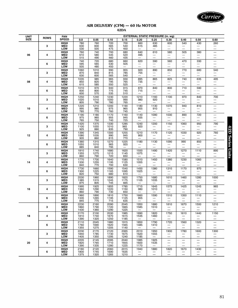
81
AIR DELIVERY (CFM) — 60 Hz MOTOR42DA
UNITSIZE ROWS FAN
SPEEDEXTERNAL STATIC PRESSURE (in. wg)
0.0 0.05 0.10 0.15 0.20 0.25 0.30 0.40 0.50 0.60
06
3HIGH 780 760 720 700 660 630 600 540 430 260MED 630 600 565 540 515 485 — — — —LOW 530 505 475 450 — — — — — —
4HIGH 760 740 700 680 640 610 580 505 380 —MED 610 580 545 520 495 — — — — —LOW 515 490 460 435 — — — — — —
6HIGH 740 720 680 660 620 590 560 470 330 —MED 595 565 530 505 — — — — — —LOW 505 480 450 — — — — — — —
08
3HIGH 1060 1010 990 955 920 890 850 770 680 540MED 870 840 815 785 755 — — — — —LOW 630 600 565 540 — — — — — —
4HIGH 1035 985 965 930 895 865 825 740 635 495MED 850 820 795 765 735 — — — — —LOW 615 585 550 525 — — — — — —
6HIGH 1010 970 940 915 870 840 800 710 590 —MED 830 800 775 745 715 — — — — —LOW 600 570 535 510 — — — — — —
10
3HIGH 1250 1240 1230 1220 1210 1160 1100 970 840 700MED 1020 1010 1000 990 980 920 — — — —LOW 805 790 780 765 — — — — — —
4HIGH 1220 1210 1200 1190 1180 1130 1070 940 810 —MED 995 985 975 965 955 910 — — — —LOW 785 770 760 745 — — — — — —
6HIGH 1190 1180 1170 1160 1140 1090 1030 890 720 —MED 975 965 955 945 935 — — — — —LOW 765 750 740 725 — — — — — —
12
3HIGH 1420 1375 1330 1285 1240 1200 1150 1060 950 790MED 1100 1055 1010 965 920 — — — — —LOW 925 880 835 790 — — — — — —
4HIGH 1390 1345 1300 1255 1210 1170 1120 1030 920 760MED 1080 1035 990 945 900 — — — — —LOW 905 860 815 770 — — — — — —
6HIGH 1360 1315 1270 1225 1180 1130 1090 990 850 —MED 1055 1010 965 920 — — — — — —LOW 885 840 795 — — — — — — —
14
3HIGH 1810 1740 1680 1620 1550 1490 1420 1270 1110 890MED 1355 1275 1215 1145 1075 — — — — —LOW 860 790 720 650 — — — — — —
4HIGH 1770 1700 1640 1580 1510 1450 1380 1230 1060 —MED 1330 1255 1195 1125 1055 — — — — —LOW 840 770 700 630 — — — — — —
6HIGH 1730 1660 1590 1540 1450 1380 1310 1170 970 —MED 1300 1225 1165 1095 1025 — — — — —LOW 820 750 680 610 — — — — — —
16
3HIGH 2030 1960 1890 1820 1750 1680 1610 1460 1280 1000MED 1385 1315 1245 1175 1105 1035 — — — —LOW 875 805 745 665 — — — — — —
4HIGH 1995 1925 1855 1785 1715 1645 1575 1425 1245 965MED 1360 1290 1220 1150 980 1010 — — — —LOW 860 790 730 650 — — — — — —
6HIGH 1960 1890 1810 1750 1660 1590 1510 1350 1110 —MED 1335 1265 1195 1125 955 — — — — —LOW 845 775 715 635 — — — — — —
18
3HIGH 2230 2160 2090 2045 1950 1880 1810 1670 1500 1210MED 1860 1790 1720 1665 1585 1510 — — — —LOW 1430 1360 1290 1225 — — — — — —
4HIGH 2170 2100 2030 1985 1890 1820 1750 1610 1440 1150MED 1810 1740 1670 1615 1535 1460 — — — —LOW 1390 1320 1250 1185 — — — — — —
6HIGH 2110 2045 1980 1915 1850 1790 1720 1560 1320 —MED 1760 1690 1620 1565 1485 1410 — — — —LOW 1355 1275 1205 1140 — — — — — —
20
3HIGH 2230 2170 2120 2065 2010 1950 1900 1780 1600 1300MED 1840 1785 1730 1675 1620 1555 — — — —LOW 1405 1350 1295 1240 1185 — — — — —
4HIGH 2205 2145 2095 2040 1985 1925 — — — —MED 1820 1765 1710 1655 1600 1535 — — — —LOW 1390 1335 1280 1225 1170 — — — — —
6HIGH 2180 2120 2060 2015 1940 1880 1820 1670 1430 —MED 1800 1745 1690 1635 — — — — — —LOW 1375 1320 1265 1210 — — — — — —
42D
Series U
nits
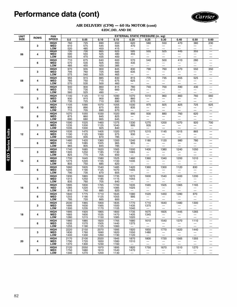
82
AIR DELIVERY (CFM) — 60 Hz MOTOR (cont)42DC,DD, AND DE
UNITSIZE ROWS FAN
SPEEDEXTERNAL STATIC PRESSURE (in. wg)
0.0 0.05 0.10 0.15 0.20 0.25 0.30 0.40 0.50 0.60
06
3HIGH 760 725 690 650 620 580 550 470 380 230MED 610 575 545 505 470 — — — — —LOW 520 485 450 415 — — — — — —
4HIGH 735 700 665 625 595 555 525 445 355 —MED 590 555 525 480 455 — — — — —LOW 505 470 435 400 — — — — — —
6HIGH 710 675 640 600 570 540 500 410 280 —MED 570 535 505 460 435 — — — — —LOW 485 455 420 385 — — — — — —
08
3HIGH 970 935 900 845 830 790 760 670 550 350MED 795 760 725 685 635 — — — — —LOW 575 540 505 465 — — — — — —
4HIGH 955 915 885 830 815 775 735 655 525 —MED 785 750 715 675 625 — — — — —LOW 570 535 500 460 — — — — — —
6HIGH 940 900 860 815 780 740 700 590 430 —MED 770 735 700 660 610 — — — — —LOW 560 525 490 — — — — — — —
10
3HIGH 1140 1125 1110 1090 1070 1010 960 860 760 660MED 930 915 900 880 860 — — — — —LOW 735 725 710 690 670 — — — — —
4HIGH 1105 1090 1070 1055 1030 975 925 825 725 625MED 905 890 875 855 835 — — — — —LOW 715 705 690 670 — — — — — —
6HIGH 1070 1055 1030 1020 990 930 880 760 620 —MED 875 860 845 825 — — — — — —LOW 690 680 665 645 — — — — — —
12
3HIGH 1590 1525 1460 1375 1330 1270 1200 1070 920 700MED 1235 1200 1125 1040 995 935 — — — —LOW 1035 1000 925 840 — — — — — —
4HIGH 1535 1470 1405 1320 1275 1215 1145 1015 865 —MED 1190 1125 1060 975 930 — — — — —LOW 1000 935 870 785 — — — — — —
6HIGH 1480 1420 1360 1300 1240 1180 1120 980 780 —MED 1145 1085 1025 965 905 — — — — —LOW 965 905 845 785 — — — — — —
14
3HIGH 1740 1685 1620 1565 1500 1400 1380 1240 1050 —MED 1305 1250 1185 1130 1065 — — — — —LOW 825 770 705 650 — — — — — —
4HIGH 1700 1645 1580 1525 1460 1360 1340 1200 1010 —MED 1275 1220 1155 1100 1035 — — — — —LOW 805 750 685 620 — — — — — —
6HIGH 1660 1605 1540 1485 1420 1360 1300 1120 830 —MED 1245 1190 1125 1070 1005 — — — — —LOW 790 735 670 605 — — — — — —
16
3HIGH 1930 1865 1800 1735 1670 1600 1540 1400 1200 —MED 1315 1250 1185 1115 1055 — — — — —LOW 835 760 705 640 — — — — — —
4HIGH 1895 1830 1765 1700 1635 1565 1505 1365 1165 —NED 1285 1220 1155 1085 1025 — — — — —LOW 815 740 685 620 — — — — — —
6HIGH 1840 1775 1710 1645 1580 1520 1450 1280 970 —MED 1255 1190 1125 1055 995 — — — — —LOW 795 720 665 600 — — — — — —
18
3HIGH 2030 1965 1900 1835 1770 1710 1640 1480 1300 —MED 1695 1630 1565 1500 1435 1375 — — — —LOW 1300 1235 1170 1105 1040 — — — — —
4HIGH 1995 1920 1865 1800 1735 1675 1605 1445 1265 —MED 1665 1600 1535 1470 1405 1345 — — — —LOW 1280 1215 1150 1085 1020 — — — — —
6HIGH 1960 1885 1820 1765 1680 1610 1540 1370 1110 —MED 1635 1570 1505 1440 1375 — — — — —LOW 1255 1190 1125 1060 — — — — — —
20
3HIGH 2220 2150 2070 1995 1920 1850 1770 1620 1440 —MED 1830 1760 1690 1620 1550 1480 — — — —LOW 1400 1330 1260 1190 1120 — — — — —
4HIGH 2170 2100 2020 1945 1870 1800 1720 1565 1355 —MED 1790 1720 1650 1580 1510 — — — — —LOW 1370 1300 1230 1160 — — — — — —
6HIGH 2120 2050 1970 1895 1820 1750 1670 1510 1270 —MED 1750 1680 1610 1540 1470 — — — — —LOW 1340 1270 1200 1130 — — — — — —
Performance data (cont)4
2D
Ser
ies
Uni
ts
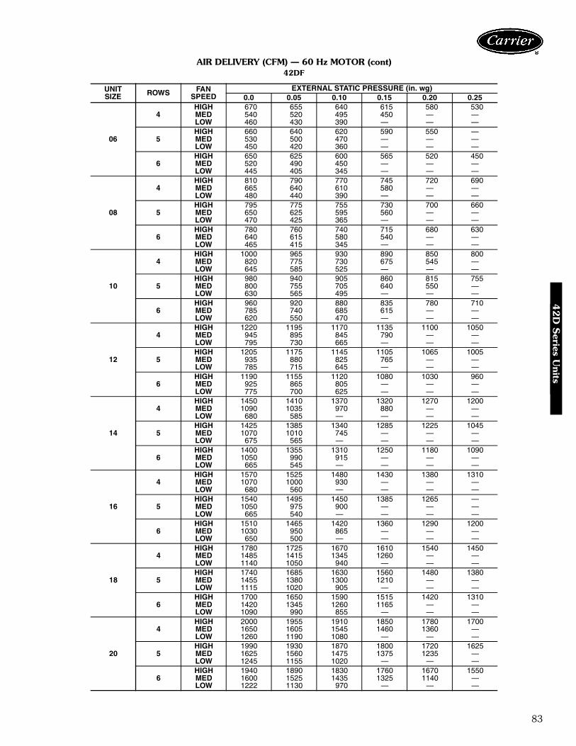
83
AIR DELIVERY (CFM) — 60 Hz MOTOR (cont)42DF
UNITSIZE ROWS FAN
SPEEDEXTERNAL STATIC PRESSURE (in. wg)
0.0 0.05 0.10 0.15 0.20 0.25
06
4HIGH 670 655 640 615 580 530MED 540 520 495 450 — —LOW 460 430 390 — — —
5HIGH 660 640 620 590 550 —MED 530 500 470 — — —LOW 450 420 360 — — —
6HIGH 650 625 600 565 520 450MED 520 490 450 — — —LOW 445 405 345 — — —
08
4HIGH 810 790 770 745 720 690MED 665 640 610 580 — —LOW 480 440 390 — — —
5HIGH 795 775 755 730 700 660MED 650 625 595 560 — —LOW 470 425 365 — — —
6HIGH 780 760 740 715 680 630MED 640 615 580 540 — —LOW 465 415 345 — — —
10
4HIGH 1000 965 930 890 850 800MED 820 775 730 675 545 —LOW 645 585 525 — — —
5HIGH 980 940 905 860 815 755MED 800 755 705 640 550 —LOW 630 565 495 — — —
6HIGH 960 920 880 835 780 710MED 785 740 685 615 — —LOW 620 550 470 — — —
12
4HIGH 1220 1195 1170 1135 1100 1050MED 945 895 845 790 — —LOW 795 730 665 — — —
5HIGH 1205 1175 1145 1105 1065 1005MED 935 880 825 765 — —LOW 785 715 645 — — —
6HIGH 1190 1155 1120 1080 1030 960MED 925 865 805 — — —LOW 775 700 625 — — —
14
4HIGH 1450 1410 1370 1320 1270 1200MED 1090 1035 970 880 — —LOW 680 585 — — — —
5HIGH 1425 1385 1340 1285 1225 1045MED 1070 1010 745 — — —LOW 675 565 — — — —
6HIGH 1400 1355 1310 1250 1180 1090MED 1050 990 915 — — —LOW 665 545 — — — —
16
4HIGH 1570 1525 1480 1430 1380 1310MED 1070 1000 930 — — —LOW 680 560 — — — —
5HIGH 1540 1495 1450 1385 1265 —MED 1050 975 900 — — —LOW 665 540 — — — —
6HIGH 1510 1465 1420 1360 1290 1200MED 1030 950 865 — — —LOW 650 500 — — — —
18
4HIGH 1780 1725 1670 1610 1540 1450MED 1485 1415 1345 1260 — —LOW 1140 1050 940 — — —
5HIGH 1740 1685 1630 1560 1480 1380MED 1455 1380 1300 1210 — —LOW 1115 1020 905 — — —
6HIGH 1700 1650 1590 1515 1420 1310MED 1420 1345 1260 1165 — —LOW 1090 990 855 — — —
20
4HIGH 2000 1955 1910 1850 1780 1700MED 1650 1605 1545 1460 1360 —LOW 1260 1190 1080 — — —
5HIGH 1990 1930 1870 1800 1720 1625MED 1625 1560 1475 1375 1235 —LOW 1245 1155 1020 — — —
6HIGH 1940 1890 1830 1760 1670 1550MED 1600 1525 1435 1325 1140 —LOW 1222 1130 970 — — —
42D
Series U
nits
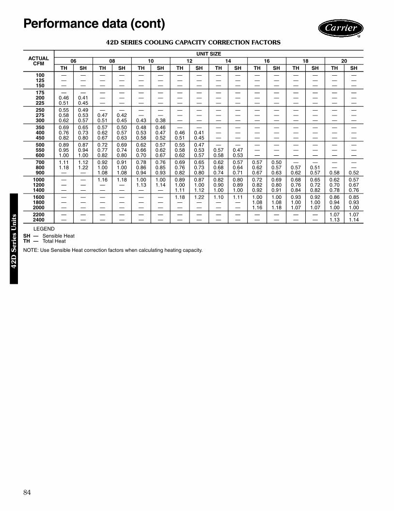
84
42D SERIES COOLING CAPACITY CORRECTION FACTORS
LEGEND
NOTE: Use Sensible Heat correction factors when calculating heating capacity.
ACTUALCFM
UNIT SIZE06 08 10 12 14 16 18 20
TH SH TH SH TH SH TH SH TH SH TH SH TH SH TH SH100 — — — — — — — — — — — — — — — —125 — — — — — — — — — — — — — — — —150 — — — — — — — — — — — — — — — —175 — — — — — — — — — — — — — — — —200 0.46 0.41 — — — — — — — — — — — — — —225 0.51 0.45 — — — — — — — — — — — — — —250 0.55 0.49 — — — — — — — — — — — — — —275 0.58 0.53 0.47 0.42 — — — — — — — — — — — —300 0.62 0.57 0.51 0.45 0.43 0.38 — — — — — — — — — —350 0.69 0.65 0.57 0.50 0.48 0.46 — — — — — — — — — —400 0.76 0.73 0.62 0.57 0.53 0.47 0.46 0.41 — — — — — — — —450 0.82 0.80 0.67 0.63 0.58 0.52 0.51 0.45 — — — — — — — —500 0.89 0.87 0.72 0.69 0.62 0.57 0.55 0.47 — — — — — — — —550 0.95 0.94 0.77 0.74 0.66 0.62 0.58 0.53 0.57 0.47 — — — — — —600 1.00 1.00 0.82 0.80 0.70 0.67 0.62 0.57 0.58 0.53 — — — — — —700 1.11 1.12 0.92 0.91 0.78 0.76 0.69 0.65 0.62 0.57 0.57 0.50 — — — —800 1.18 1.22 1.00 1.00 0.86 0.85 0.76 0.73 0.68 0.64 0.62 0.57 0.57 0.51 — —900 — — 1.08 1.08 0.94 0.93 0.82 0.80 0.74 0.71 0.67 0.63 0.62 0.57 0.58 0.52
1000 — — 1.16 1.18 1.00 1.00 0.89 0.87 0.82 0.80 0.72 0.69 0.68 0.65 0.62 0.571200 — — — — 1.13 1.14 1.00 1.00 0.90 0.89 0.82 0.80 0.76 0.72 0.70 0.671400 — — — — — — 1.11 1.12 1.00 1.00 0.92 0.91 0.84 0.82 0.78 0.761600 — — — — — — 1.18 1.22 1.10 1.11 1.00 1.00 0.93 0.92 0.86 0.851800 — — — — — — — — — — 1.08 1.08 1.00 1.00 0.94 0.932000 — — — — — — — — — — 1.16 1.18 1.07 1.07 1.00 1.002200 — — — — — — — — — — — — — — 1.07 1.072400 — — — — — — — — — — — — — — 1.13 1.14
SH — Sensible HeatTH — Total Heat
Performance data (cont)4
2D
Ser
ies
Uni
ts
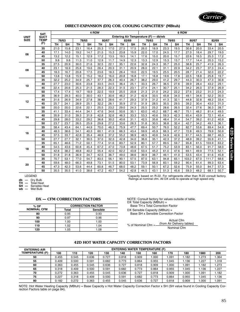
85
DIRECT-EXPANSION (DX) COIL COOLING CAPACITIES* (MBtuh)
LEGEND *Capacity based on R-22. For refrigerants other than R-22 consult factory.Ratings at nominal cfm. All DX units to operate at high speed only.
DX — CFM CORRECTION FACTORS NOTE: Consult factory for values outside of table.DX Total Capacity (MBtuh) =
Base TH x Total Correction FactorDX Sensible Capacity (MBtuh) =
Base SH x Sensible Correction Factor
42D HOT WATER CAPACITY CORRECTION FACTORS
NOTE: Hot Water Heating Capacity (MBtuh) = Base Capacity x Hot Water Capacity Correction Factor x SH (SH value found in Cooling Capacity Cor-rection Factors table on page 84).
UNITSIZE
SAT.SUCTTEMP
(F)
4 ROW 6 ROWEntering Air Temperature (F) — db/wb
76/63 78/65 80/67 82/69 76/63 78/65 80/67 82/69TH SH TH SH TH SH TH SH TH SH TH SH TH SH TH SH
06
35 21.0 15.8 23.1 16.4 25.3 17.0 27.5 17.5 26.0 18.9 23.3 19.5 30.8 20.0 33.4 20.540 17.1 14.0 19.2 14.7 21.5 15.3 23.8 15.9 22.0 17.0 24.5 17.7 27.0 18.4 29.7 19.045 13.2 12.2 15.1 12.9 17.2 13.5 19.5 14.1 17.6 15.0 20.0 15.7 22.6 16.5 25.3 17.250 9.8 9.8 11.3 11.0 12.9 11.7 14.9 12.3 13.3 12.9 15.3 13.7 17.7 14.4 20.3 15.2
08
35 27.5 20.9 30.0 21.6 32.5 22.1 35.1 22.6 32.8 24.3 35.7 25.0 38.8 25.7 41.9 26.340 23.1 18.9 25.8 19.6 28.4 20.3 31.1 20.9 28.0 22.1 31.1 22.9 34.2 23.7 37.3 24.445 18.3 16.7 20.8 17.5 23.6 18.3 26.4 19.0 22.5 19.5 25.5 20.5 28.7 21.4 32.0 22.250 13.8 13.8 15.9 15.2 18.2 16.0 20.8 16.8 17.1 16.8 19.6 17.8 22.5 18.8 25.8 19.7
10
35 32.2 25.2 34.9 25.7 37.7 26.3 40.4 26.7 38.2 29.0 41.2 29.7 44.3 30.3 47.3 30.840 27.7 23.0 30.6 23.8 33.5 24.5 36.4 25.1 33.3 26.7 36.5 27.6 39.9 28.4 43.2 29.145 22.4 20.6 25.3 21.5 28.3 22.3 31.5 23.1 27.4 24.1 30.7 25.1 34.2 26.0 37.9 26.950 17.4 17.4 19.7 18.9 22.5 19.9 25.5 20.8 21.3 21.0 24.2 22.2 27.6 23.2 31.3 24.3
12
35 36.9 29.3 40.0 30.0 43.1 30.6 46.2 31.2 42.8 33.5 45.8 34.0 49.1 34.6 52.2 35.040 31.6 26.9 34.9 27.8 38.3 28.6 41.7 29.3 37.9 31.2 41.3 32.1 44.8 32.8 48.2 33.445 25.7 24.1 28.9 25.1 32.2 26.1 35.9 27.0 31.9 28.5 35.5 29.5 39.2 30.4 43.0 31.350 20.0 20.0 22.6 22.1 25.5 23.2 29.0 24.3 25.5 25.2 28.6 26.5 32.4 27.6 36.3 28.7
14
35 41.1 33.4 44.4 34.1 47.6 34.6 50.6 35.1 63.0 45.2 68.7 46.7 75.1 48.2 81.4 49.540 35.9 31.0 39.3 31.9 42.8 32.6 46.3 33.3 53.3 40.6 59.3 42.3 65.4 43.9 72.1 45.445 29.8 28.0 33.2 29.2 36.8 30.2 40.6 31.1 42.5 35.6 48.4 31.4 54.7 39.2 61.2 40.950 23.7 23.7 26.5 25.9 29.8 27.2 33.6 28.3 31.8 30.5 36.8 32.4 42.7 34.2 49.1 36.1
16
35 58.4 43.4 64.1 44.9 70.0 46.3 75.9 47.7 69.4 50.7 76.0 52.2 82.7 53.6 89.4 54.940 48.3 38.6 54.1 40.3 60.1 41.9 66.3 43.4 59.9 45.9 66.3 47.7 72.8 49.3 79.9 50.945 37.5 33.7 42.8 35.4 48.9 37.2 55.2 38.9 48.5 40.6 54.9 42.6 61.7 44.5 68.7 46.350 27.7 27.7 32.1 30.5 37.0 32.3 42.8 34.0 36.6 35.1 42.3 37.2 48.9 39.2 55.9 41.1
18
35 65.1 48.6 71.2 50.1 77.4 51.6 83.7 52.9 80.1 57.7 89.5 59.7 95.8 61.5 103.9 63.240 54.5 43.6 60.8 45.4 67.2 47.0 73.8 48.6 67.5 51.7 75.2 53.9 83.1 56.0 91.7 58.045 42.8 38.2 48.8 40.2 55.4 42.0 62.2 43.8 53.4 45.2 61.0 47.6 69.1 49.9 77.5 52.150 31.8 31.8 36.9 34.7 42.5 36.7 49.0 38.6 39.9 38.7 46.1 41.0 53.5 43.4 61.6 45.8
20
35 70.7 53.1 77.0 54.7 83.5 56.1 90.1 57.5 87.0 63.1 94.8 65.1 103.2 67.0 111.7 68.640 59.6 48.0 66.3 49.8 73.1 51.5 80.0 53.1 73.9 56.9 83.1 59.2 90.4 61.4 99.3 63.445 47.3 42.3 53.8 44.4 60.8 46.7 68.0 48.2 59.1 50.1 67.2 52.6 75.9 55.0 84.7 57.350 35.5 35.5 41.0 38.6 47.2 40.7 54.2 42.8 44.5 43.1 51.3 45.6 59.3 48.2 68.1 50.7
db — Dry BulbTH — Total HeatSH — Sensible Heatwb — Wet Bulb
% OFNOMINAL CFM
CORRECTION FACTORTotal Sensible
80 0.95 0.9390 0.97 0.96
100 1.00 1.00110 1.02 1.04120 1.05 1.08
% of Nominal Cfm =
Actual Cfm(from Air Delivery tables)
Nominal Cfm
ENTERING AIRTEMPERATURE (F)
ENTERING WATER TEMPERATURE (F)100 110 120 130 140 150 160 170 180 1980 200
50 0.455 0.545 0.636 0.727 0.818 0.909 1.000 1.091 1.182 1.273 1.36455 0.409 0.500 0.591 0.682 0.773 0.864 0.955 1.045 1.136 1.227 1.31860 0.363 0.455 0.545 0.636 0.727 0.818 0.909 1.000 1.091 1.182 1.27365 0.318 0.409 0.500 0.591 0.682 0.773 0.864 0.955 1.045 1.136 1.22770 0.272 0.363 0.455 0.545 0.636 0.727 0.818 0.909 1.000 1.091 1.18275 0.227 0.318 0.409 0.500 0.591 0.682 0.773 0.864 0.955 1.045 1.13680 0.182 0.272 0.363 0.455 0.545 0.636 0.727 0.818 0.909 1.000 1.091
42D
Series U
nits
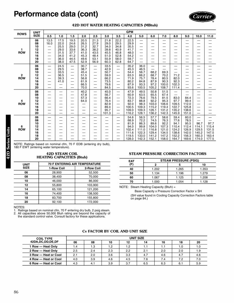
86
42D HOT WATER HEATING CAPACITIES (MBtuh)
NOTE: Ratings based on nominal cfm, 70 F EDB (entering dry bulb),180 F EWT (entering water temperature).
42D STEAM COILHEATING CAPACITIES (Btuh)
NOTES:1. Ratings based on nominal cfm, 70 F entering dry bulb, 2 psig steam.2. All capacities above 50,000 Btuh rating are beyond the capacity of
the standard control valve. Consult factory for these applications.
STEAM PRESSURE CORRECTION FACTORS
NOTE: Steam Heating Capacity (Btuh) =Base Capacity x Pressure Correction Factor x SH
(SH value found in Cooling Capacity Correction Factors tableon page 84.)
Cv FACTOR BY COIL AND UNIT SIZE
ROWS UNITSIZE
GPM0.5 1.0 1.5 2.0 2.5 3.0 3.5 4.0 5.0 6.0 7.0 8.0 9.0 10.0 11.0
1ROW
06 13.5 17.5 19.5 20.5 21.3 21.8 22.2 22.5 — — — — — — —08 16.0 22.0 24.6 26.5 27.9 29.0 29.5 29.9 — — — — — — —10 — 25.5 29.0 31.2 32.7 34.0 34.8 35.5 — — — — — — —12 — 29.0 33.6 36.3 38.2 39.8 40.9 41.7 — — — — — — —14 — 31.5 37.7 41.0 43.5 45.5 46.8 48.0 — — — — — — —16 — 34.0 41.2 45.3 48.4 51.0 52.8 54.2 — — — — — — —18 — 36.0 44.5 49.6 53.1 55.9 58.0 59.7 — — — — — — —20 — 38.0 47.5 52.9 56.9 60.3 62.8 64.7 — — — — — — —
2ROW
06 — 24.5 — 30.7 — 33.5 — 35.2 36.0 — — — — — —08 — 29.5 — 38.7 — 42.9 — 45.3 46.5 — — — — — —10 — 33.5 — 45.4 — 50.7 — 54.4 56.7 68.2 69.3 — — — —12 — 36.5 — 51.5 — 59.0 — 63.3 66.2 68.7 70.2 71.2 — — —14 — 39.3 — 56.8 — 66.2 — 71.9 75.7 78.4 80.5 82.0 — — —16 — 41.0 — 61.9 — 73.5 — 80.2 84.8 87.9 90.3 92.3 — — —18 — — — 66.5 — 79.6 — 87.9 93.3 97.2 100.0 102.3 — — —20 — — — 70.0 — 84.5 — 93.6 100.5 105.2 108.7 111.4 — — —
4ROW
06 — — — 40.2 — 45.0 — 47.9 49.5 50.8 51.5 — — — —08 — — — 47.8 — 56.7 — 60.9 63.5 65.5 67.4 — — — —10 — — — 57.3 — 66.4 — 72.3 76.6 79.5 81.5 83.0 84.4 — —12 — — — 64.0 — 76.4 — 83.7 88.8 92.2 95.3 97.7 99.4 — —14 — — — — — 82.9 — 92.0 98.3 103.0 106.6 109.5 112.0 — —16 — — — — — 89.4 — 100.5 109.3 115.2 119.4 122.7 125.8 — —18 — — — — — 95.7 — 109.0 109.3 126.1 131.2 135.2 138.6 — —20 — — — — — 101.3 — 116.2 128.1 136.2 142.3 145.9 151.0 — —
6ROW
06 — — — — — — — 54.6 56.5 57.7 58.6 59.4 60.0 — —08 — — — — — — — 68.9 72.2 74.5 76.3 77.6 78.5 — —10 — — — — — — — 81.9 86.3 89.6 92.2 94.1 95.5 96.7 97.712 — — — — — — — 94.0 99.8 104.0 107.3 110.4 112.4 114.1 115.414 — — — — — — — 102.4 111.0 116.8 121.0 124.2 126.9 129.5 131.516 — — — — — — — 111.6 122.3 129.4 134.5 138.6 142.0 145.2 147.518 — — — — — — — 119.5 133.0 141.2 147.2 152.2 156.3 160.3 163.420 — — — — — — — 128.0 142.3 152.1 158.0 164.7 169.6 174.0 177.5
UNITSIZE
70 F ENTERING AIR TEMPERATURE1-Row Coil 2-Row Coil
06 28,900 52,50008 38,400 70,00010 46,000 86,00012 55,800 103,90014 65,100 121,20016 74,400 138,50018 83,700 155,80020 92,100 172,000
EAT(F)
STEAM PRESSURE (PSIG)2 5 10
40 1.202 1.265 1.35350 1.134 1.196 1.27960 1.067 1.125 1.20870 1.000 1.054 1.128
COIL TYPE42DA,DC,DD,DE,DF
UNIT SIZE06 08 10 12 14 16 18 20
1 Row — Heat Only 1.4 1.3 1.2 1.2 1.1 1.1 1.0 1.02 Row — Heat Only 2.5 2.4 2.3 2.2 2.1 2.0 2.0 1.93 Row — Heat or Cool 2.1 2.0 3.6 3.3 4.7 4.6 4.7 4.64 Row — Heat or Cool 4.0 3.9 4.6 4.5 7.6 7.4 7.2 7.06 Row — Heat or Cool 4.3 4.1 3.9 3.7 6.5 6.3 6.1 5.9
Performance data (cont)4
2D
Ser
ies
Uni
ts

87
42D ELECTRIC HEATER DATA
LEGENDFLA — Full Load AmpsNOTES:1. All heaters are single-stage and single-phase.2. In all units using over 48 amps, the heating elements are sub-
divided and protected. Additional cost is incurred because of addedcomponents.
3. A separate power source is required for motor and heaters exceptwhen motors and heaters of same voltage are ordered in conjunctionwith a single power source wiring option. This option, which meetsNEC requirements, consists of a factory-furnished and installedjunction box and fuse for 6.25 amp (max) fan and control circuit con-nection to a single power source. Power supply circuit to unit must befield furnished and installed in accordance with applicable codes.
UL ListingThe UL Listing signifies that Carrier’s fan coil units havebeen examined by UL and comply with the organization’sapplicable standards. The Canadian Standards Association(CSA) and Underwriters’ Laboratories of Canada alsoapprove the fan coil units.
HEATERVOLTAGE
HEATER kW2.0 3.0 4.0 5.0 6.0 7.0 8.0 9.0 10.0 12.0 14.0
FLA120 16.7 25.0 — — — — — — — — —208 9.6 14.4 19.2 24.0 28.8 33.7 38.5 43.3 48.1 57.7 67.3240 8.3 12.5 16.7 20.8 25.0 29.2 33.3 37.5 41.7 50.0 58.3277 7.2 10.8 14.4 18.0 21.7 25.3 28.9 32.5 36.1 43.3 50.5
Electrical data4
2D
Series U
nits

88
42DA MOTOR DATA
*Total motor amps and watts shown for units with 2 motors (size 12 through 20).NOTE: Motor nameplate amps may vary.
42DC,DD AND DE MOTOR DATA
*Total motor amps and watts shown for units with 2 motors (size 12 through 20).NOTE: Motor nameplate amps may vary.
VOLTS/PH-Hz FANSPEED
FANSPEED(RPM)
UNIT SIZE
06 08 10 12*
NominalHp Watts Amps Nominal
Hp Watts Amps NominalHp Watts Amps Nominal
Hp Watts Amps
115-1-60H 1200
1/10
280 2.701/8
330 3.101/5
470 5.601/10 (2)
550 5.30M 980 200 2.00 225 2.25 360 3.70 305 2.92L 790 140 1.50 135 1.44 240 2.60 205 1.93
208/230-1-60H 1200
1/10
240 1.101/8
420 1.801/5
430 2.001/10 (2)
450 2.10M 980 175 0.74 280 1.26 260 1.20 325 1.45L 790 110 0.50 155 0.73 165 0.80 215 1.00
277-1-60H 1200
1/10
275 1.151/8
275 1.211/5
425 1.621/5 (2)
550 2.40M 980 175 0.69 175 0.69 260 1.04 355 1.38L 790 90 0.33 90 0.34 155 0.65 175 0.67
VOLTS/PH-Hz FANSPEED
FANSPEED(RPM)
UNIT SIZE
14* 16* 18* 20*
NominalHp Watts Amps Nominal
Hp Watts Amps NominalHp Watts Amps Nominal
Hp Watts Amps
115-1-60H 1200
1/10 (2)650 6.40
1/5 (2)900 8.80
1/5 (2)1180 11.80
1/4 (2)1180 11.80
M 980 440 4.60 705 6.90 770 8.30 770 8.30L 790 280 3.00 430 4.20 460 5.30 460 5.30
208/230-1-60H 1200
1/10 (2)465 2.10
1/5 (2)740 3.60
1/5 (2)925 4.10
1/4 (2)925 4.10
M 980 325 1.45 360 1.80 5.45 2.48 545 2.48L 790 220 1.00 220 1.20 330 1.60 330 1.60
277-1-60H 1200
1/10 (2)735 2.70
1/5 (2)940 3.60
1/5 (2)980 3.72
1/4 (2)980 3.72
M 980 510 1.90 560 2.20 550 2.20 550 2.20L 790 330 1.30 335 1.40 320 1.40 320 1.40
VOLTS/PH-Hz FANSPEED
FANSPEED(RPM)
UNIT SIZE
06 08 10 12*
NominalHp Watts Amps Nominal
Hp Watts Amps NominalHp Watts Amps Nominal
Hp Watts Amps
115-1-60H 1200
1/10
265 2.601/8
310 3.001/5
440 4.501/10 (2)
550 5.40M 980 195 1.95 220 2.30 330 3.40 390 3.90L 790 155 1.54 140 1.50 225 2.50 305 3.10
208/230-1-60H 1200
1/10
235 1.001/8
325 1.451/5
410 1.801/10 (2)
700 3.20M 980 165 0.72 210 0.95 250 1.10 430 2.00L 790 110 0.49 135 0.62 160 0.76 305 1.48
277-1-60H 1200
1/10
275 1.101/8
275 1.401/5
395 1.511/10 (2)
535 2.40M 980 175 0.70 175 0.69 260 1.10 360 1.40L 790 90 0.33 90 0.34 155 0.65 190 0.70
VOLTS/PH-Hz FANSPEED
FANSPEED(RPM)
UNIT SIZE
14* 16* 18* 20*
NominalHp Watts Amps Nominal
Hp Watts Amps NominalHp Watts Amps Nominal
Hp Watts Amps
115-1-60H 1200
1/10 (2)690 6.80
1/5 (2)900 9.80
1/5 (2)1015 10.20
1/5 (2)1020 10.20
M 980 560 5.40 725 7.70 745 7.80 750 7.80L 790 280 3.50 450 5.24 450 5.30 460 5.30
208/230-1-60H 1200
1/10 (2)720 3.30
1/5 (2)680 3.00
1/5 (2)820 3.70
1/4 (2)820 3.70
M 980 440 2.00 445 2.00 500 2.20 510 2.20L 790 310 1.48 285 1.33 330 1.50 330 1.50
277-1-60H 1200
1/10 (2)700 2.65
1/5 (2)830 3.20
1/5 (2)900 3.50
1/4 (2)925 3.52
M 980 495 1.96 510 2.00 550 2.23 550 2.23L 790 300 1.30 300 1.30 320 1.36 320 1.36
Electrical data (cont)4
2D
Ser
ies
Uni
ts

89
42DF MOTOR DATA
*Total motor amps and watts shown for units with 2 motors (size 12 through 20).NOTE: Motor nameplate amps may vary.
VOLTS/PH-Hz FANSPEED
FANSPEED(RPM)
UNIT SIZE06 08 10 12*
NominalHp Watts Amps Nominal
Hp Watts Amps NominalHp Watts Amps Nominal
Hp Watts Amps
115-1-60H 1200
1/10
260 2.401/8
275 3.101/5
380 3.701/10 (2)
490 4.40M 980 195 1.70 205 2.10 300 3.00 310 3.00L 790 125 1.15 155 1.58 210 2.00 210 2.10
208/230-1-60H 1200
1/10
235 1.001/8
230 1.051/4
410 1.801/10 (2)
450 2.00M 980 165 0.72 145 0.65 220 1.05 300 1.40L 790 105 0.48 105 0.48 160 0.75 224 1.05
277-1-60H 1200
1/10
205 0.721/10
270 0.901/5
285 1.271/10 (2)
370 1.44M 980 140 0.51 190 0.71 180 0.73 235 0.89L 790 90 0.31 155 0.57 95 0.37 165 0.63
VOLTS/PH-Hz FANSPEED
FANSPEED(RPM)
UNIT SIZE14* 16* 18* 20*
NominalHp Watts Amps Nominal
Hp Watts Amps NominalHp Watts Amps Nominal
Hp Watts Amps
115-1-60H 1200
1/10 (2)520 5.00
1/5 (2)670 6.50
1/5 (2)800 7.40
1/5 (2)840 8.20
M 980 320 3.00 470 4.80 670 6.60 685 6.60L 790 210 2.10 300 3.10 420 4.10 435 4.20
208/230-1-60H 1200
1/10 (2)470 2.10
1/5 (2)590 2.90
1/5 (2)705 3.20
1/4 (2)810 3.44
M 980 340 1.50 440 2.10 420 2.00 495 2.20L 790 230 1.10 300 1.45 315 1.55 320 1.50
277-1-60H 1200
1/10 (2)450 1.60
1/5 (2)470 1.70
1/5 (2)620 2.80
1/4 (2)870 3.30
M 980 330 1.28 350 1.20 420 1.65 545 2.20L 790 250 0.90 250 0.90 230 0.95 320 1.36
42D
Series U
nits

90
ARI capacity ratingsThe 42S series fan coil units are certified in compliancewith the Air Conditioning and Refrigeration Institute (ARI)Industry Standard 440-98 for room fan coil units.Approved standard ratings are tabulated below:
ARI APPROVED STANDARD RATINGS — STANDARD CAPACITY COIL
ARI APPROVED STANDARD RATINGS — HIGH-CAPACITY COIL
*Table values are listed for each half of 42SJ units and master/slave.†Motor type, permanent split capacitor, operating at 115-1-60 voltage.
NOTE: Ratings based on motor at high fan speed, standard air and drycoil operation, 10 degrees F water temperature rise; entering air tem-peratures of 80 F db, 67 F wb; entering water temperature 45 F.
UNITTYPE*
UNIT SIZECOIL
NOMINALCFM GPM
COOLING CAPACITY POWER INPUT(WATTS)†Total Heat Btuh Sensible Heat Btuh
42S
03 300 2.4 11,500 7,000 8504 400 2.9 13,600 9,000 11506 600 4.5 21,900 14,000 13508 800 5.5 27,500 17,800 21010 1000 7.7 37,700 24,500 29012 1200 8.1 43,100 28,400 380
UNITTYPE*
UNIT SIZECOIL
NOMINALCFM GPM
COOLING CAPACITY POWER INPUT(WATTS)†Total Heat Btuh Sensible Heat Btuh
42S
03 300 2.6 12,200 7,300 8504 400 3.3 15,600 9,600 11506 600 5.5 26,000 15,300 13508 800 6.4 31,400 19,500 21010 1000 8.7 42,200 25,600 29012 1200 9.5 49,400 31,300 380
Model number nomenclature
Size (cfm)03 - 30004 - 40006 - 60008 - 80010 - 100012 - 1200
ModelG - Furred-In SingleH - CabinetJ - Furred-In Back-to-Back
42S - Vertical Stack Unit
42S G A 06 - - - - - - - - -
Series
42S
Ser
ies
Uni
ts
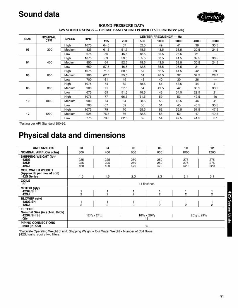
91
SOUND PRESSURE DATA42S SOUND RATINGS — OCTAVE BAND SOUND POWER LEVEL RATINGS* (db)
*Testing per ARI Standard 350-86.
Physical data and dimensions
*Calculate Operating Weight of unit: Shipping Weight + Coil Water Weight x Number of Coil Rows.†42SJ units require two filters.
SIZE NOMINALCFM SPEED RPM
CENTER FREQUENCY — Hz125 250 500 1000 2000 4000 8000
03 300High 1075 64.5 57 52.5 49 41 39 35.5Medium 825 61.5 51.5 48.5 43.5 33.5 30.5 24.5Low 675 56 45.5 42.5 35.5 25.5 21 —
04 400High 1075 69 59.5 55.5 50.5 41.5 39.5 36.5Medium 850 64 52.5 48.5 43.5 33.5 30.5 24.5Low 650 57.5 46.5 42.5 35.5 25.5 21 —
06 600High 1075 71.5 60.5 57 52.5 44.5 42 39Medium 900 67.5 55.5 51 46.5 37 34.5 28.5Low 700 61 49 45 40 30 26 —
08 800High 1075 74 62 58.5 54 48.5 44 41Medium 900 71 57.5 54 49.5 42 38.5 33.5Low 675 65 51.5 48.5 43 34.5 29.5 21
10 1000High 1075 77 66.5 61.5 59 53 49.5 46Medium 900 74 64 58.5 55 48.5 46 41Low 700 67 59 55 51 45 40.5 35.5
12 1200High 1075 79 70 65.5 62 56.5 51.5 47.5Medium 925 76.5 66 62.5 58 52 47 42.5Low 775 70.5 62.5 59 54 47.5 41.5 37
UNIT SIZE 42S 03 04 06 08 10 12NOMINAL AIRFLOW (cfm) 300 400 600 800 1000 1200SHIPPING WEIGHT (lb)*
42SG 225 225 250 250 275 27542SH 225 225 250 250 275 27542SJ 420 420 470 470 520 520
COIL WATER WEIGHT(Approx lb per row of coil)
42S Series 1.6 1.6 2.3 2.3 3.1 3.1COILS
FPI 14 fins/inchMOTOR (qty)
42SG,SH 1 1 1 1 1 142SJ 2 2 2 2 2 2
BLOWER (qty)42SG,SH 1 1 1 1 1 142SJ 2 2 2 2 2 2
FILTERSNominal Size (in.) (1-in. thick)
42SG,SH,SJ 121/2 x 241/4 161/4 x 263/4 201/2 x 291/4Qty 1†
PIPING CONNECTIONSInlet (in. OD) 1/2
Sound data4
2S
Series U
nits
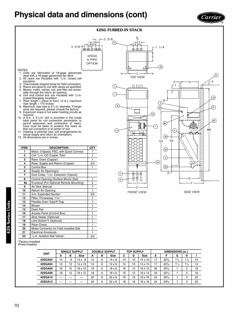
92
Physical data and dimensions (cont)
42SGA4–PIPEOPTION
TOP VIEW
SIDE VIEWFRONT VIEW
42SG FURRED-IN STACK
NOTES:1. Units are fabricated of 18-gage galvanized
steel with a 16-gage galvanized fan deck.2. All risers are insulated with 1/2-in. closed cell
insulation.3. Thermostats shipped loose for field connection.4. Risers are piped to coil with valves as specified.5. Blower, motor, valves, coil, and filter are acces-
sible through the return air opening.6. Unit and control box are insulated with 1/2-in.
coated fiberglass insulation.7. Riser length = [(floor to floor) +2 in.], maximum
riser length = 115 inches.8. Maximum riser size is 21/2-in. diameter. If larger
sizes are required, please consult the factory.9. Expansion loops in hot water heating circuits as
required.10. A 9-in. x 21/4-in. slot is provided in the inside
back panel for coil connection penetration topermit expansion and contraction of risers.Care must be taken to position the risers sothat coil connection is at center of slot.
11. Drawing is pictorial (see unit arrangements foractual supply and return air orientation).
12. All dimensions are in inches.
*Factory-Installed.†Field-Installed.
ITEM DESCRIPTION QTY1 Motor, 3-Speed, PSC, with Quick Connect 12 Coil 1/2-in. OD Copper Tube 13 Riser, Drain (Copper) 14 Riser, Supply and Return (Copper) 2/45 Control Box 16 Supply Air Opening(s)7 Duct Collar, 1/2-in. Extension (Typical)
8 Control Opening (Surface Mount Stat) 18a Knockout (For Optional Remote Mounting) 29 Air Vent, Manual 1
10 Return Air Opening 111 3-in. Expanded Section 3/512 Filter, Throwaway, 1-in.* 113 Flexible Drain Tube/P-Trap 114 Blower 115 Drain Pan 116 Access Panel (Control Box) 117 Strip Heater (Optional) 118 Limit Switch*† (Optional) 119 Riser Chase 120 Molex Connector for Field Installed Stat 121 Electrical Knockouts 122 1/2-in. Isolation Ball Valves* 2/4
UNITSINGLE SUPPLY DOUBLE SUPPLY TOP SUPPLY DIMENSIONS (in.)
A B Size A B Size C D Size E F G H I42SGA03 14 8 14 x 8 14 6 14 x 6 14 10 14 x 10 17 223/8 11/2 11/2 14
42SGA04 14 12 14 x 12 14 6 14 x 6 14 10 14 x 10 17 223/8 11/2 11/2 14
42SGA06 18 10 18 x 10 18 6 18 x 6 16 12 16 x 12 20 253/8 1 2 18
42SGA08 18 12 18 x 12 18 6 18 x 6 16 12 16 x 12 20 253/8 1 2 18
42SGA10 — — — 22 8 22 x 8 18 16 18 x 16 24 293/8 1 3 22
42SGA12 — — — 22 8 22 x 8 18 16 18 x 16 24 293/8 1 3 22
42S
Ser
ies
Uni
ts

93
42SHA
4–PIPE
OPTIONS
HR HS D CR CS R SD
TOP VIEW
FRONT VIEW SIDE VIEW
42SH CABINET
NOTES:1. Units are fabricated of 18-gage galvanized
steel with a 16-gage galvanized fan deck,painted with Arctic White.
2. 3 speed switch and thermostat are unitmounted.
3. Risers are piped to coil with valves asspecified.
4. Blower, motor, valves, coil, and filter areaccessible through the return air opening.
5. Unit is insulated with coated fiberglass.6. Control box is insulated with 1/2-in. insulation
for unit mounted controls.7. Riser length = [(floor to floor) +2 in.], maximum
riser length = 115 inches.8. Maximum riser size is 21/2-in. diameter. If
larger sizes are required, please consult thefactory.
9. Expansion loops in hot water heating circuitsas required.
10. A 9-in. x 21/4-in. slot is provided in the insideback panel for coil connection penetration topermit expansion and contraction of risers.Care must be taken to position the risers sothat coil connection is at center of slot.
11. Drawing is pictorial (see unit arrangements foractual supply and return air orientation).
12. 42SHA available in front return only.13. All dimensions are in inches.
*Factory-Installed.†Field-Installed.
ITEM DESCRIPTION QTY1 Motor, 3-Speed, PSC Series “L”2 Coil 1/2-in. OD Tube 13 Riser, Drain (Type “M” Copper) 14 Riser, Supply and Return (Type “M” Copper) 2/45 Control Box 16 Cabinet Camlocks7 3 Speed Switch
8 T-Stat 19 D.D. Steel Core Grille Assembly 1
10 Air Vent, Manual 111 Hinged Control Access Door 112 Filter, Throwaway, 1-in.* 113 Flexible Drain Tube/P-Trap 114 Blower 115 Drain Pan 116 Return Air Panel 117 Electrical Access Panel 118 3-in. Expansion Section 3/519 Strip Heater (Optional) 120 Limit Switch*† (Optional) 121 Electrical Knockouts 122 1/2-in. Isolation Ball Valves* 2/4
UNITSINGLE SUPPLY DOUBLE SUPPLY TOP
SUPPLY DIMENSIONS (in.)
A B Size A B Size C D E F G42SHA03 14 8 14 x 8 14 6 14 x 6 17 223/8 11/2 221/8 143/4
42SHA04 14 12 14 x 12 14 8 14 x 8 17 223/8 11/2 221/8 143/4
42SHA06 14 12 14 x 12 14 8 14 x 8 20 253/8 2 265/8 173/4
42SHA08 14 16 14 x 16 14 10 14 x 10 20 253/8 2 265/8 173/4
42SHA10 18 16 18 x 16 14 12 14 x 12 24 293/8 3 311/8 173/4
42SHA12 18 16 18 x 16 14 12 14 x 12 24 293/8 3 311/8 173/4
42S
Series U
nits

94
Physical data and dimensions (cont)
‘A’SIDE
4–PIPEOPTION
‘A’SIDE
‘B’SIDE
TOP VIEW
FRONT VIEW SIDE VIEW
42SJ BACK-TO-BACK FURRED-IN STACK
NOTES:1. Units are fabricated of 18-gage galva-
nized steel with a 16-gage galvanizedfan deck.
2. All risers are insulated with 1/2-in.closed cell insulation.
3. Thermostats shipped loose for fieldconnection.
4. Risers are piped to coil with valves asspecified.
5. Blower, motor, valves, coil, and filterare accessible through the return airopening.
6. Unit and control box are insulated with1/2-in. coated fiberglass insulation.
7. Riser length = [(floor to floor) +2 in.],maximum riser length = 115 inches.
8. Maximum riser size is 21/2-in. diame-ter. If larger sizes are required, pleaseconsult the factory.
9. Expansion loops in hot water heatingcircuits as required.
10. A 9-in. x 21/4-in. slot is provided in theinside back panel for coil connectionpenetration to permit expansion andcontraction of risers. Care must betaken to position the risers so that coilconnection is at center of slot.
11. Drawing is pictorial (see unit arrange-ments for actual supply and return airorientation.
12. All dimensions are in inches.
*Factory-Installed.†Field-Installed.
ITEM DESCRIPTION QTY1 Motor, 3-Speed, PSC, w/Quick Connect 22 Coil 1/2-in. OD Copper Tube 23 Riser, Drain (Copper) 14 Riser, Supply and Return (Copper) 2/45 Control Box 26 Supply Air Opening(s)7 Duct Collar, 1/2-in. Extension (Typical)
8 Control Opening (Surface Mount Stat) 29 Air Vent, Manual 2
10 Return Air Opening 211 3-in. Expanded Section 3/512 Filter, Throwaway, 1-in.* 2
ITEM DESCRIPTION QTY13 Flexible Drain Tube/P-Trap 214 Blower 215 Drain Pan 216 Knockout (For Optional Remote Mounting) 217 1/2-in. Isolation Ball Valves* 4/818 Access Panel (Control Box) 219 Strip Heater* (Optional) 220 Limit Switch*† (Optional) 221 Molex Connector for Field Installed Stat 222 Thermafiber Insulation23 Gypsum Board, 5/8-in. Type “X” 1
24 Electrical Knockouts
UNITSINGLE SUPPLY DOUBLE SUPPLY TOP SUPPLY DIMENSIONS (in.)
A B Size A B Size C D Size E F G H I J42SJA03 14 8 14 x 8 14 6 14 x 6 14 10 14 x 10 17 223/8 11/2 11/2 14 395/8
42SJA04 14 12 14 x 12 14 6 14 x 6 14 10 14 x 10 17 223/8 11/2 11/2 14 395/8
42SJA06 18 10 18 x 10 18 6 18 x 6 16 12 16 x 12 20 253/8 1 2 18 455/8
42SJA08 18 12 18 x 12 18 6 18 x 6 16 12 16 x 12 20 253/8 1 2 18 455/8
42SJA10 — — — 22 8 22 x 8 18 16 18 x 16 24 293/8 1 3 22 535/8
42SJA12 — — — 22 8 22 x 8 18 16 18 x 16 24 293/8 1 3 22 535/8
42S
Ser
ies
Uni
ts
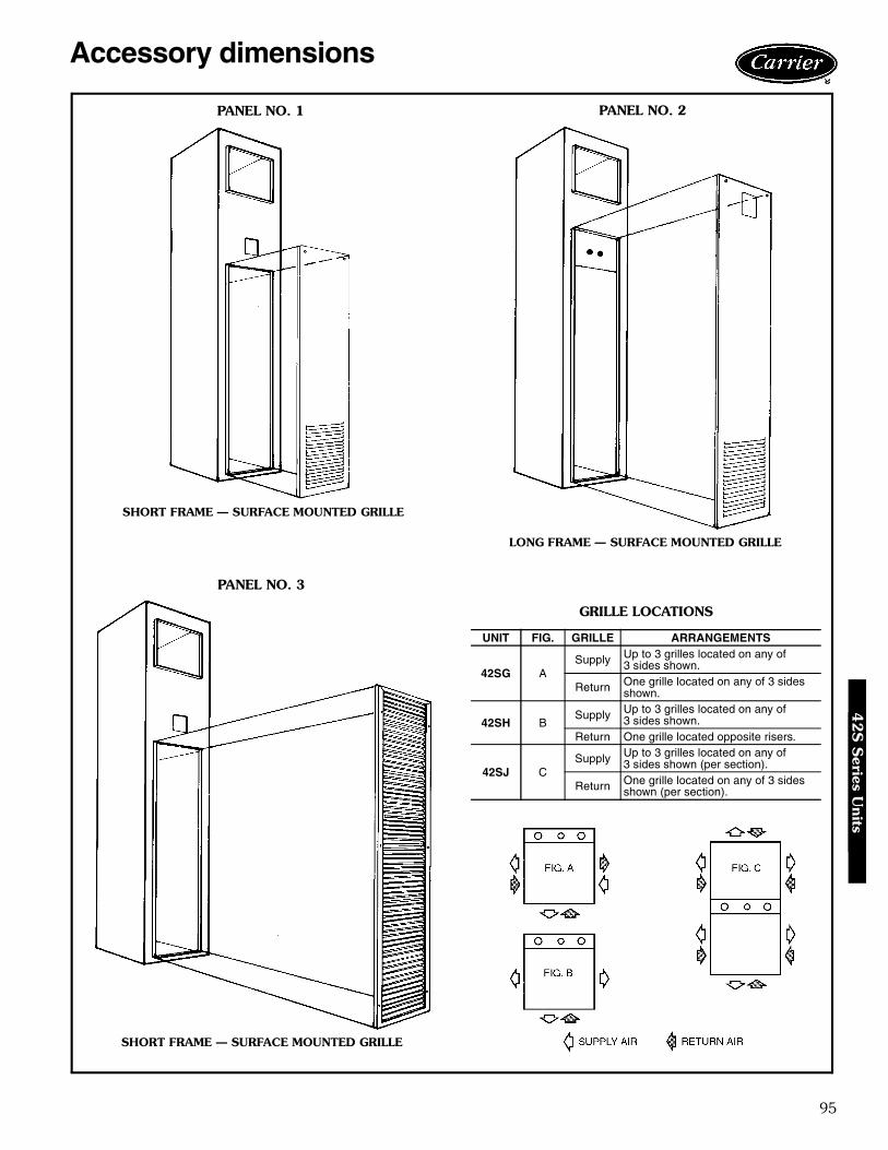
95
Accessory dimensions
GRILLE LOCATIONS
UNIT FIG. GRILLE ARRANGEMENTS
42SG ASupply Up to 3 grilles located on any of
3 sides shown.
Return One grille located on any of 3 sidesshown.
42SH BSupply Up to 3 grilles located on any of
3 sides shown.Return One grille located opposite risers.
42SJ CSupply Up to 3 grilles located on any of
3 sides shown (per section).
Return One grille located on any of 3 sidesshown (per section).
PANEL NO. 1 PANEL NO. 2
SHORT FRAME — SURFACE MOUNTED GRILLE
LONG FRAME — SURFACE MOUNTED GRILLE
PANEL NO. 3
SHORT FRAME — SURFACE MOUNTED GRILLE
42S
Series U
nits

96
Accessory dimensions (cont)
PANEL NO. 5
LONG FRAME — FLUSH MOUNTED GRILLE
PANEL NO. 4
SHORT FRAME — FLUSH MOUNTED GRILLE
42S
Ser
ies
Uni
ts
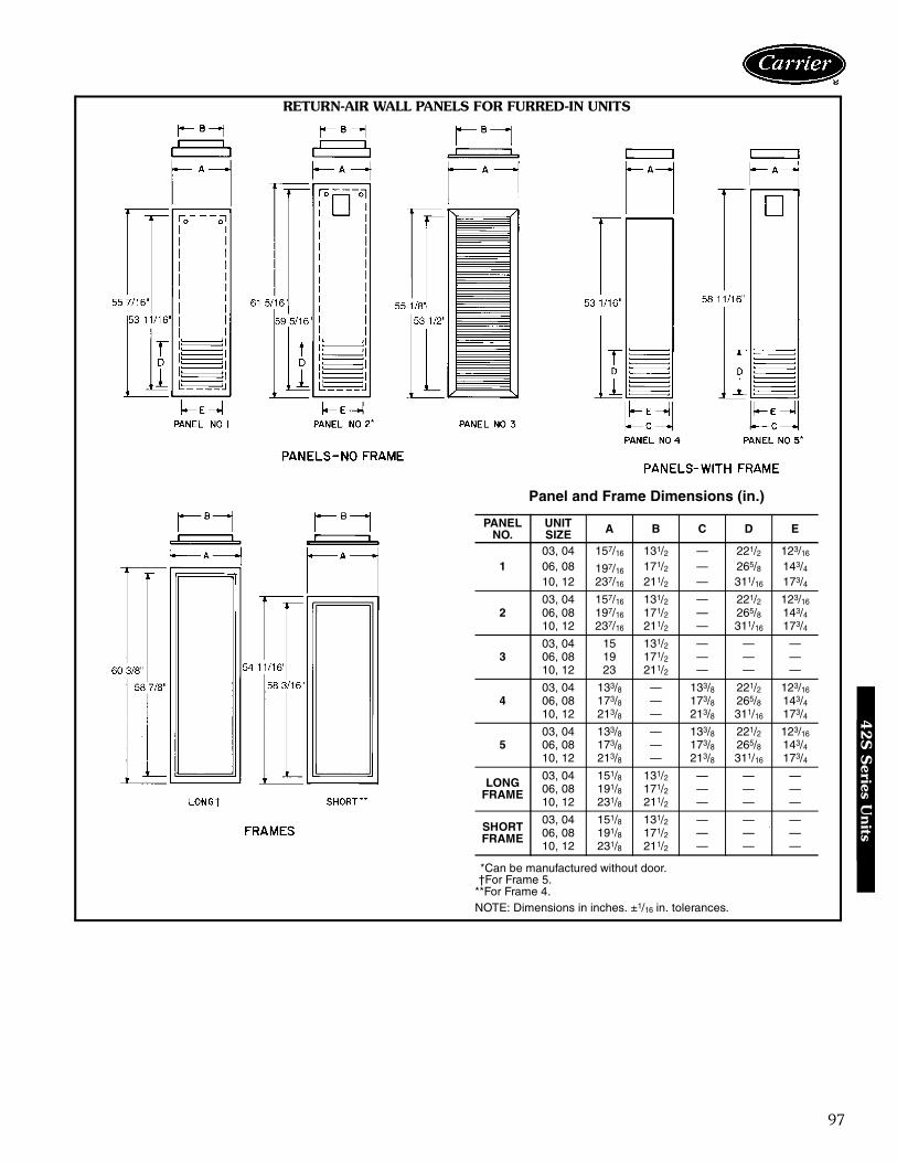
97
Panel and Frame Dimensions (in.)
*Can be manufactured without door.†For Frame 5.
**For Frame 4.NOTE: Dimensions in inches. ±1/16 in. tolerances.
PANELNO.
UNITSIZE A B C D E
103, 04 157/16 131/2 — 221/2 123/16
06, 08 197/16 171/2 — 265/8 143/410, 12 237/16 211/2 — 311/16 173/4
203, 04 157/16 131/2 — 221/2 123/16
06, 08 197/16 171/2 — 265/8 143/410, 12 237/16 211/2 — 311/16 173/4
303, 04 15 131/2 — — —06, 08 19 171/2 — — —10, 12 23 211/2 — — —
403, 04 133/8 — 133/8 221/2 123/16
06, 08 173/8 — 173/8 265/8 143/410, 12 213/8 — 213/8 311/16 173/4
503, 04 133/8 — 133/8 221/2 123/16
06, 08 173/8 — 173/8 265/8 143/410, 12 213/8 — 213/8 311/16 173/4
LONGFRAME
03, 04 151/8 131/2 — — —06, 08 191/8 171/2 — — —10, 12 231/8 211/2 — — —
SHORTFRAME
03, 04 151/8 131/2 — — —06, 08 191/8 171/2 — — —10, 12 231/8 211/2 — — —
RETURN-AIR WALL PANELS FOR FURRED-IN UNITS
42S
Series U
nits

98
AIR DELIVERY
AIR DELIVERY WITH HIGH-STATIC FAN
LEGENDESP — External Static Pressure
UNIT SIZE COILCFM AT 0.0 ESP FOR FAN SPEED HIGH SPEED CFM AT ESP INDICATEDLow Med High 0.05 0.10 0.15 0.20 0.25
42SG,SH,SJ
03
3 Row
260 300 440 410 380 340 300 24004 300 410 510 480 450 420 380 34006 490 570 710 670 630 590 540 48008 580 650 840 800 760 710 670 61010 640 960 1130 1100 1070 1040 1000 97012 750 940 1260 1230 1200 1160 1130 109003
4 Row
250 290 420 390 350 320 280 22004 280 400 490 470 430 400 360 32006 480 560 590 560 520 480 430 38008 460 590 800 760 720 670 620 56010 630 940 1090 1060 1040 1010 980 95012 740 920 1250 1220 1180 1150 1110 1070
UNIT SIZE COILHigh Speed CFM AT ESP INDICATED0.2 0.25 0.3 0.4 0.5
42SG,SH,SJ
033 Row 505 485 465 420 3704 Row 485 465 445 400 3505 Row 465 445 425 380 330
043 Row 530 510 485 440 4004 Row 510 490 465 420 3805 Row 490 470 445 400 360
063 Row 860 820 790 720 6604 Row 840 800 770 700 6405 Row 820 780 750 680 620
083 Row 1020 985 940 845 7804 Row 1000 965 920 825 7605 Row 980 945 900 805 740
103 Row 1265 1235 1205 1140 10754 Row 1245 1215 1185 1120 10555 Row 1225 1195 1165 1100 1035
123 Row 1320 1300 1290 1235 11604 Row 1300 1280 1270 1215 11405 Row 1280 1260 1250 1195 1120
Performance data4
2S
Ser
ies
Uni
ts

99
42S COOLING CAPACITY (GPM) 3-ROW COIL
42S COOLING CAPACITY (GPM) 4-ROW COIL
LEGEND
NOTE: All capacities are given in thousands of Btuh (MBtuh).
UNITSIZE GPM
75 F DB/63 F WB 80 F DB/67 F WB 85 F DB/71 F WB40 F EWT 45 F EWT 50 F EWT 40 F EWT 45 F EWT 50 F EWT 40 F EWT 45 F EWT 50 F EWT
∆T TCb SCb ∆T TCb SCb ∆T TCb SCb ∆T TCb SCb ∆T TCb SCb ∆T TCb SCb ∆T TCb SCb ∆T TCb TCb ∆T TCb SCb
031 16.4 8.2 6.7 13.5 6.8 6.0 10.9 5.4 5.2 19.5 9.8 7.4 16.5 8.2 6.7 13.6 6.8 6.0 22.9 11.4 8.0 19.7 9.9 7.4 16.6 8.3 6.7
1.5 13.0 9.7 7.4 10.5 7.9 6.6 8.2 6.2 5.8 15.7 11.8 8.3 13.1 9.9 7.4 10.6 7.9 6.6 18.7 14.0 9.0 16.0 12.0 8.2 13.2 9.9 7.42 10.8 10.8 7.9 8.6 8.6 6.9 6.6 6.6 6.0 13.1 13.1 8.8 10.8 10.8 7.8 8.6 8.6 6.9 15.5 15.5 9.6 13.2 13.2 8.7 10.9 10.9 7.8
2.5 9.1 11.4 8.2 7.3 9.1 7.2 5.5 6.9 6.2 11.1 13.9 9.2 9.2 11.6 8.2 7.3 9.2 7.2 13.3 16.6 10.1 11.3 14.2 9.1 9.3 11.7 8.1
041 18.0 9.0 7.8 15.1 7.5 7.0 12.3 6.2 6.0 21.3 10.6 8.6 18.2 9.1 7.8 15.2 7.6 7.0 24.8 12.4 9.3 21.5 10.7 8.6 18.3 9.1 7.9
1.5 14.5 10.9 8.8 11.9 8.9 7.8 9.5 7.1 6.8 17.4 13.1 9.7 14.6 11.0 8.8 11.9 8.9 7.9 20.5 15.4 10.5 17.6 13.2 9.7 14.6 11.0 8.82 12.2 12.2 9.4 9.8 9.8 8.3 7.6 7.6 7.2 14.6 14.6 10.4 12.2 12.2 9.3 9.8 9.8 8.3 17.4 17.4 11.3 14.8 14.8 10.3 12.2 12.2 9.3
2.5 10.4 13.0 9.8 8.4 10.4 8.6 6.4 8.0 7.5 12.7 15.8 10.9 10.5 13.1 9.7 8.3 10.4 8.6 15.1 18.8 11.9 12.8 16.0 10.8 10.6 13.2 9.7
06
1 22.7 11.3 10.1 19.6 9.8 9.0 15.8 7.9 7.9 26.3 13.1 11.1 23.1 11.6 10.2 20.0 10.0 9.1 30.0 15.0 12.1 26.7 13.4 11.2 23.6 11.8 10.31.5 18.6 13.9 11.8 15.9 11.9 10.7 13.3 10.0 9.3 21.7 16.3 13.0 18.9 14.2 11.9 16.2 12.2 10.8 25.1 18.8 14.0 22.1 16.6 13.1 19.2 14.4 12.02 15.8 15.8 12.9 13.3 13.3 11.6 11.0 11.0 10.2 18.7 18.7 14.1 16.0 16.0 12.9 13.5 13.5 11.7 21.9 21.9 15.3 19.0 19.0 14.2 16.3 16.3 13.13 12.3 18.5 14.2 10.2 15.2 12.7 8.1 12.2 11.2 14.9 22.3 15.7 12.5 18.8 14.2 10.2 15.4 12.8 17.6 26.3 17.1 15.1 22.7 15.6 12.7 19.0 14.24 10.1 20.3 15.0 8.2 16.4 13.2 6.4 12.8 11.6 12.3 24.6 16.7 10.2 20.5 14.9 8.2 16.5 13.3 14.5 29.1 18.2 12.4 24.9 16.5 10.3 20.7 14.9
08
1 24.0 12.0 11.0 20.7 10.3 9.7 16.7 8.4 8.4 27.8 13.9 12.3 24.5 12.2 11.1 20.4 10.2 10.2 31.7 15.8 13.4 28.3 14.2 12.4 25.0 12.5 11.31.5 20.2 15.1 13.4 17.3 13.0 11.9 14.0 10.5 10.5 23.5 17.6 14.8 20.5 15.4 13.5 17.7 13.3 12.1 27.0 20.2 16.0 23.9 17.9 14.9 20.9 15.7 13.72 17.3 17.3 14.8 14.7 14.7 13.3 12.3 12.3 11.5 20.4 20.4 16.3 17.6 17.6 15.0 15.0 15.0 13.5 23.6 23.6 17.6 20.7 20.7 16.4 17.9 17.9 15.13 13.7 20.5 16.6 11.4 17.1 14.9 9.3 13.9 13.0 16.4 24.6 18.2 13.9 20.8 16.7 11.5 17.2 15.0 19.3 28.9 19.8 16.6 25.0 18.3 14.0 21.0 16.74 11.4 22.8 17.6 9.2 18.5 15.7 7.3 14.7 13.7 13.7 27.3 19.4 11.4 22.8 17.6 9.3 18.5 15.7 16.1 32.3 21.2 13.8 27.6 19.3 11.5 23.0 17.6
10
1.5 22.6 16.9 15.2 19.5 14.7 13.5 15.4 11.5 11.5 26.2 19.6 16.9 23.1 17.4 15.4 20.1 15.0 13.7 29.9 22.4 18.4 26.8 20.1 17.1 23.7 17.8 15.62 19.9 19.9 17.4 17.2 17.2 15.5 13.5 13.5 13.5 23.1 23.1 19.2 20.3 20.3 17.6 17.6 17.6 15.7 26.6 26.6 20.8 23.7 23.7 19.4 20.8 20.8 17.83 16.0 23.9 19.9 13.6 20.4 18.0 11.3 17.0 15.7 18.9 28.3 21.9 16.3 24.4 20.1 13.8 20.8 18.2 22.0 32.9 23.7 19.2 28.8 22.0 16.6 24.9 20.34 13.5 26.9 21.5 11.2 22.4 19.3 9.2 18.4 16.9 16.1 32.2 23.6 13.7 27.4 21.6 11.4 22.8 19.5 18.9 37.8 25.7 16.4 32.8 23.7 13.9 27.8 21.76 10.3 30.9 23.4 8.4 25.1 20.7 6.6 19.8 18.1 12.5 37.4 25.9 10.4 31.2 23.3 8.4 25.2 20.8 14.7 44.2 28.2 12.6 37.9 25.7 10.5 31.5 23.3
12
1.5 23.3 17.4 16.0 19.1 14.3 14.3 15.8 11.9 11.9 27.0 20.3 17.9 23.3 17.9 16.2 19.3 14.5 14.5 30.8 23.1 19.6 27.7 20.7 18.1 24.4 18.3 16.42 20.7 20.7 18.5 17.9 17.9 16.5 14.1 14.1 14.1 24.1 24.1 20.6 21.2 21.2 18.8 18.4 18.4 16.7 27.6 27.6 22.4 24.7 24.7 20.8 21.8 21.8 19.03 16.9 25.3 21.7 14.4 21.6 19.5 12.0 18.1 16.8 19.8 29.7 23.9 17.2 25.8 21.9 14.7 22.1 19.7 23.0 34.5 25.8 20.2 30.3 24.1 17.6 26.4 22.24 14.3 28.6 23.5 12.0 24.0 21.2 9.9 19.8 18.4 17.0 34.0 25.9 14.5 29.1 23.7 12.2 24.4 21.4 19.9 39.8 28.1 17.3 34.6 26.0 14.8 29.6 23.96 11.0 33.1 25.7 9.0 27.0 22.9 7.2 21.6 20.0 13.3 39.8 28.4 11.1 33.3 25.7 9.0 27.1 23.1 15.7 47.0 30.9 13.4 40.3 28.3 11.2 33.6 25.8
UNITSIZE GPM
75 F DB/63 F WB 80 F DB/67 F WB 85 F DB/71 F WB40 F EWT 45 F EWT 50 F EWT 40 F EWT 45 F EWT 50 F EWT 40 F EWT 45 F EWT 50 F EWT
∆T TCb SCb ∆T TCb SCb ∆T TCb SCb ∆T TCb SCb ∆T TCb SCb ∆T TCb SCb ∆T TCb SCb ∆T TCb TCb ∆T TCb SCb
03
1 18.2 9.1 7.2 15.6 7.8 6.6 13.2 6.6 5.8 21.3 10.7 7.9 18.5 9.2 7.3 15.9 7.9 6.6 24.6 12.3 8.5 21.6 10.8 7.9 18.8 9.4 7.31.5 14.3 10.7 8.0 11.9 8.9 7.2 9.8 7.3 6.4 17.1 12.8 8.8 14.5 10.9 8.0 12.1 9.1 7.2 20.0 15.0 9.6 17.4 13.0 8.8 14.7 11.1 8.02 11.8 11.8 8.5 9.7 9.1 7.6 7.7 7.7 6.7 14.3 14.3 9.5 12.1 12.1 8.5 9.9 9.9 7.6 16.9 16.9 10.4 14.6 14.6 9.4 12.3 12.3 8.5
2.5 10.1 12.6 8.9 8.3 10.3 7.9 6.5 8.1 6.8 12.3 15.3 9.9 10.3 12.9 8.9 8.4 10.5 7.9 14.6 18.2 10.9 12.6 15.8 9.9 10.6 13.2 8.83 8.8 13.2 9.2 7.2 10.8 8.1 5.6 8.3 7.0 10.7 16.1 10.3 9.1 13.6 9.2 7.3 10.9 8.0 12.8 19.2 11.4 11.1 16.6 10.2 9.2 13.9 9.1
04
1 20.2 10.1 8.5 17.4 8.7 7.6 14.8 7.4 6.7 23.4 11.7 9.2 20.5 10.3 8.5 17.8 8.9 7.7 26.9 13.4 10.0 23.8 11.9 9.3 21.0 10.5 8.61.5 16.1 12.0 9.5 13.6 10.2 8.6 11.3 8.5 7.6 19.0 14.3 10.4 16.3 12.2 9.6 13.8 10.4 8.7 22.1 16.6 11.3 19.3 14.5 10.4 16.6 12.4 9.62 13.5 13.5 10.2 11.2 11.2 9.2 9.1 9.1 8.1 16.1 16.1 11.3 13.7 13.7 10.2 11.3 11.3 9.2 19.0 19.0 12.2 16.4 16.4 11.2 13.9 13.9 10.2
2.5 11.7 14.6 10.7 9.6 12.0 9.5 7.6 9.5 8.4 14.1 17.6 11.9 11.9 14.9 10.7 9.7 12.1 9.6 16.6 20.8 13.0 14.4 18.0 11.8 12.1 15.1 10.73 10.3 15.4 11.1 8.4 12.6 9.8 6.6 9.9 8.6 12.5 18.7 12.4 10.5 15.7 11.1 8.5 12.8 9.9 14.8 22.2 13.6 12.8 19.2 12.3 10.7 16.0 11.1
06
1 26.0 13.0 11.1 22.7 11.4 10.0 19.4 9.7 8.7 29.9 15.0 12.2 26.5 13.3 11.2 23.3 11.6 10.1 33.9 17.0 13.1 30.5 15.2 12.3 27.2 13.6 11.32 18.2 18.2 14.3 15.5 15.5 13.0 13.0 13.0 11.5 21.5 21.5 15.7 18.5 18.5 14.4 15.8 15.8 13.1 25.0 25.0 16.9 21.8 21.8 15.7 18.8 18.8 14.43 14.2 21.3 15.8 11.8 17.6 14.1 9.5 14.2 12.5 17.0 25.6 17.5 14.4 21.7 15.8 11.9 17.8 14.2 20.1 30.1 19.1 17.4 26.1 17.4 14.6 21.9 15.84 11.7 23.3 16.8 9.5 18.9 14.8 7.4 14.9 12.9 14.0 28.1 18.6 11.8 23.6 16.6 9.5 19.1 14.8 16.6 33.2 20.3 14.3 28.6 18.4 11.9 23.8 16.55 9.8 24.5 17.3 8.0 19.9 15.2 6.1 15.4 13.2 11.9 29.8 19.3 10.0 24.9 17.2 8.0 20.0 15.2 14.2 35.4 21.2 12.2 30.4 19.1 10.1 25.3 17.1
08
1 27.5 13.7 12.2 23.8 11.9 10.8 18.9 9.4 9.4 31.7 15.8 13.5 28.0 14.0 12.3 24.3 12.2 10.9 35.9 17.9 14.6 32.3 16.1 13.6 28.6 14.3 12.42 20.2 20.2 16.7 17.3 17.3 15.1 14.6 14.6 13.2 23.6 23.6 18.3 20.5 20.5 16.8 17.7 17.7 15.2 27.2 27.2 19.7 24.0 24.0 18.3 20.9 20.9 16.93 16.0 23.9 18.7 13.4 20.0 16.8 11.0 16.5 14.8 19.0 28.5 20.6 16.2 24.3 18.8 13.5 20.3 16.9 22.2 33.3 22.3 19.3 28.9 20.5 16.3 24.5 18.84 13.2 26.5 20.0 10.8 21.6 17.7 8.7 17.3 15.6 15.8 31.7 22.0 13.3 26.6 19.8 10.9 21.8 17.8 18.7 37.3 23.9 16.0 32.1 21.8 13.4 26.9 19.85 11.3 28.1 20.7 9.2 22.9 18.3 7.2 18.0 16.0 13.6 34.0 23.0 11.4 28.5 20.6 9.2 23.0 18.4 16.1 40.3 25.1 13.8 34.5 22.8 11.5 28.7 20.5
10
2 22.3 22.3 19.0 19.5 19.5 17.1 14.7 14.7 14.7 25.8 25.8 20.9 22.9 22.9 19.2 20.1 20.1 17.4 29.3 29.3 22.6 26.4 26.4 21.1 23.6 23.6 19.53 18.0 27.0 22.0 15.6 23.3 19.9 13.2 19.8 17.6 21.1 31.6 24.0 18.4 27.7 22.2 16.0 24.0 20.2 24.4 36.5 25.9 21.6 32.3 24.2 18.9 28.4 22.44 15.2 30.4 23.7 12.9 25.7 21.5 10.8 21.5 19.0 18.0 36.1 26.0 15.5 31.0 23.9 13.2 26.3 21.7 21.0 42.1 28.2 18.4 36.8 26.1 15.8 31.7 24.06 11.7 35.1 26.0 9.7 29.0 23.2 7.8 23.3 20.5 14.1 42.3 28.8 11.9 35.8 26.0 9.8 29.4 23.3 16.7 50.0 31.4 14.4 43.3 28.7 12.1 36.4 26.08 9.5 38.1 27.4 7.7 31.0 24.1 6.1 24.2 21.1 11.5 46.2 30.5 9.7 38.7 27.2 7.8 31.2 24.1 13.7 54.7 33.3 11.7 47.0 30.1 9.8 39.2 27.1
12
2 23.3 23.3 20.3 20.3 20.3 18.1 15.4 15.4 15.4 26.9 26.9 22.5 23.9 23.9 20.6 20.9 20.9 18.4 30.6 30.6 24.4 27.7 27.7 22.8 24.7 24.7 20.93 19.2 28.7 24.1 16.6 24.9 21.7 14.1 21.1 18.9 22.3 33.5 26.4 19.6 29.5 24.3 17.1 25.6 22.0 25.7 38.5 28.5 22.8 34.2 26.6 20.2 30.2 24.64 16.2 32.5 26.2 13.9 27.7 23.8 11.7 23.3 20.9 19.2 38.3 28.8 16.6 33.2 26.4 14.2 28.4 24.0 22.7 44.5 31.1 19.6 39.1 28.9 17.0 33.9 26.76 12.6 37.9 28.9 10.5 31.5 25.9 8.5 25.6 22.9 15.1 45.4 31.9 12.9 38.6 29.0 10.6 31.9 26.1 17.8 53.5 34.7 15.5 46.4 31.9 13.0 39.1 29.18 10.4 41.4 30.6 8.4 33.7 27.1 6.7 26.7 23.7 12.5 50.0 33.9 10.5 41.9 30.4 8.5 34.0 27.1 14.8 59.1 36.9 12.7 50.7 33.6 10.6 42.3 30.3
∆T — Temperature Change SCb — Base Sensible Capacity from Base Cooling Capacities by Gpm chartsDB — Dry Bulb TCb — Base Total Capacity from Base Cooling Capacities by Gpm chartsEWT — Entering Water Temperature WB — Wet BulbGPM — Gallons per Minute
42S
Series U
nits

100
42S COOLING CAPACITY (∆T) 3-ROW COIL
42S COOLING CAPACITY (∆T) 4-ROW COIL
LEGEND
NOTE: All capacities are given in thousands of Btuh (MBtuh).
UNITSIZE ∆T
75 F DB/63 F WB 80 F DB/67 F WB 85 F DB/71 F WB40 F EWT 45 F EWT 50 F EWT 40 F EWT 45 F EWT 50 F EWT 40 F EWT 45 F EWT 50 F EWT
GPM TCb SCb GPM TCb SCb GPM TCb SCb GPM TCb SCb GPM TCb SCb GPM TCb SCb GPM TCb SCb GPM TCb SCb GPM TCb SCb
03
8 3.0 11.8 8.4 2.2 8.9 7.1 1.6 6.2 5.8 — — — 3.0 12.1 8.4 2.2 8.9 7.1 — — — — — — 3.1 12.3 8.410 2.2 11.1 8.1 1.6 8.1 6.7 1.1 5.7 5.4 2.9 14.4 9.4 2.2 11.2 8.0 1.6 8.1 6.7 — — — 3.0 14.8 9.3 2.3 11.4 8.012 1.7 10.2 7.7 1.2 7.3 6.3 0.9 5.1 5.0 2.3 13.6 9.0 1.7 10.3 7.6 1.2 7.4 6.3 2.9 17.2 10.3 2.3 13.8 8.9 1.7 10.4 7.614 1.3 9.3 7.2 0.9 6.6 5.9 0.7 4.6 4.5 1.8 12.7 8.7 1.4 9.4 7.2 1.0 6.6 5.9 2.3 16.3 9.9 1.8 12.9 8.6 1.4 9.5 7.316 1.0 8.3 6.8 0.7 5.8 5.5 0.5 4.0 4.0 1.5 11.7 8.2 1.1 8.5 6.8 0.8 6.0 5.5 1.9 15.3 9.5 1.5 11.9 8.2 1.1 8.6 6.9
04
8 — — — 2.7 10.6 8.7 1.9 7.5 7.2 — — — — — — 2.7 10.6 8.7 — — — — — — — — —10 2.7 13.2 9.9 1.9 9.7 8.2 1.4 6.9 6.7 3.5 17.4 11.5 2.7 13.4 9.9 1.9 9.7 8.3 — — — — — — 2.7 13.5 9.812 2.0 12.3 9.4 1.5 8.8 7.8 1.1 6.3 6.1 2.7 16.2 11.0 2.0 12.3 9.4 1.5 8.9 7.9 3.5 20.7 12.7 2.8 16.6 11.0 2.1 12.3 9.414 1.6 11.2 8.9 1.1 8.0 7.3 0.8 5.7 5.7 2.2 15.0 10.5 1.6 11.3 8.9 1.2 8.1 7.3 2.8 19.5 12.2 2.2 15.3 10.5 1.6 11.3 8.916 1.3 10.1 8.4 0.9 7.2 6.7 0.7 5.2 5.2 1.7 13.9 10.0 1.3 10.2 8.4 0.9 7.2 6.7 2.3 18.2 11.7 1.8 14.1 10.0 1.3 10.3 8.5
06
8 5.4 21.7 15.7 4.1 16.5 13.3 3.1 12.3 11.2 7.0 27.9 18.1 5.6 22.2 15.6 4.2 16.6 13.3 — — — — — — 5.6 22.6 15.610 4.1 20.4 15.1 3.1 15.3 12.7 2.3 11.4 10.5 5.3 26.3 17.4 4.1 20.6 15.0 3.1 15.5 12.8 6.6 32.9 19.8 5.4 27.0 17.3 4.2 20.9 15.012 3.1 18.8 14.3 2.3 14.1 12.1 1.8 10.6 9.8 4.1 24.8 16.8 3.2 19.2 14.4 2.4 14.4 12.2 5.2 31.3 19.1 4.2 25.3 16.6 3.3 19.5 14.414 2.5 17.2 13.6 1.9 12.9 11.4 1.4 9.4 8.9 3.3 23.1 16.0 2.5 17.6 13.7 1.9 13.3 11.6 4.2 29.5 18.4 3.4 23.6 16.0 2.6 18.0 13.816 2.0 15.7 12.8 1.5 11.9 10.6 — — — 2.7 21.2 15.2 2.0 16.1 13.0 1.5 12.3 10.8 3.5 27.7 17.6 2.7 21.9 15.3 2.1 16.5 13.1
08
8 6.4 25.7 19.0 4.9 19.4 16.1 3.6 14.4 13.5 — — — 6.5 26.1 18.9 4.9 19.5 16.2 — — — — — — 6.6 26.4 18.910 4.8 23.9 18.1 3.6 18.0 15.4 2.7 13.6 12.7 6.2 31.0 21.0 4.8 24.2 18.1 3.6 18.1 15.5 — — — 6.4 31.7 20.9 4.9 24.4 18.112 3.7 22.2 17.3 2.8 16.6 14.6 2.1 12.5 11.7 4.8 29.0 20.1 3.7 22.4 17.3 2.8 16.9 14.8 6.1 36.8 23.0 4.9 29.6 20.1 3.8 22.6 17.414 2.9 20.2 16.4 2.2 15.3 13.7 1.5 10.5 10.5 3.9 26.9 19.8 3.0 20.7 16.6 2.2 15.7 13.9 5.0 34.6 22.1 3.9 27.4 19.3 3.0 21.0 16.716 2.3 18.4 15.5 1.7 13.9 12.7 1.1 9.0 9.0 3.1 24.9 18.4 2.4 19.0 15.7 1.8 14.4 13.0 4.1 32.4 21.2 3.2 25.6 18.5 2.4 19.4 16.0
10
8 8.4 33.5 24.5 6.4 25.5 20.9 4.8 19.1 17.5 10.8 43.0 28.3 8.5 34.1 24.5 6.4 25.6 21.0 — — — — — — 8.7 34.6 24.510 6.3 31.3 23.5 4.7 23.6 19.9 3.6 17.9 16.4 8.1 40.4 27.2 6.3 31.7 23.5 4.8 23.9 20.1 10.2 50.7 30.8 8.3 41.5 27.1 6.4 32.1 23.512 4.8 28.8 22.3 3.6 21.7 18.9 2.7 16.5 15.2 6.3 38.0 26.1 4.9 29.4 22.4 3.7 22.3 19.2 8.0 48.0 29.7 6.5 38.7 26.0 5.0 29.9 22.614 3.8 26.3 21.1 2.9 20.0 17.7 1.9 13.0 13.0 5.0 35.2 24.9 3.9 27.0 21.4 3.0 20.6 18.1 6.5 45.2 28.6 5.1 36.0 24.9 4.0 27.7 21.716 3.0 23.9 19.9 2.3 18.2 16.4 — — — 4.0 32.3 23.7 3.1 24.7 20.3 2.4 19.0 16.8 5.3 42.3 27.4 4.2 33.3 23.9 3.2 25.5 20.6
12
8 9.3 37.0 27.5 7.0 28.0 23.5 5.3 21.1 19.6 — — — 9.4 37.6 27.5 7.1 28.2 23.6 — — — — — — 9.5 38.1 27.510 6.9 34.4 26.3 5.2 26.0 22.4 4.0 19.8 18.4 8.9 44.6 30.4 7.0 34.8 26.4 5.3 26.3 22.6 — — — 9.1 45.6 30.4 7.0 35.2 26.412 5.3 31.8 25.1 4.0 24.0 21.2 3.0 18.1 16.8 6.9 41.7 29.2 5.4 32.2 25.2 4.1 24.6 21.5 8.8 53.0 33.3 7.1 42.5 29.2 5.4 32.7 25.414 4.1 29.0 23.7 3.2 22.0 19.8 2.0 14.3 14.3 5.5 38.7 27.9 4.3 29.7 24.0 3.3 22.8 20.2 7.1 49.7 32.0 5.6 39.5 28.0 4.4 30.4 24.316 3.3 26.4 22.3 2.5 20.0 18.2 — — — 4.4 35.6 26.6 3.4 27.3 22.7 2.6 20.8 18.7 5.8 46.5 30.7 4.6 36.5 26.8 3.5 28.1 23.2
UNITSIZE ∆T
75 F DB/63 F WB 80 F DB/67 F WB 85 F DB/71 F WB40 F EWT 45 F EWT 50 F EWT 40 F EWT 45 F EWT 50 F EWT 40 F EWT 45 F EWT 50 F EWT
GPM TCb SCb GPM TCb SCb GPM TCb SCb GPM TCb SCb GPM TCb SCb GPM TCb SCb GPM TCb SCb GPM TCb SCb GPM TCb SCb
03
8 3.4 13.6 9.4 2.6 10.4 7.9 1.9 7.7 6.6 4.3 17.3 10.9 3.5 14.0 9.3 2.7 10.7 7.9 5.3 21.3 12.3 4.5 17.9 10.8 3.6 14.4 9.310 2.5 12.7 8.9 1.9 9.6 7.5 1.5 7.3 6.4 3.3 16.5 10.5 2.6 13.1 9.0 2.0 9.8 7.6 4.1 20.6 12.0 3.4 17.1 10.4 2.7 13.5 9.012 2.0 11.8 8.5 1.5 8.9 7.2 1.1 6.9 6.0 2.6 15.5 10.0 2.0 12.1 8.5 1.5 9.1 7.2 3.3 19.6 12.9 2.7 16.1 10.0 2.1 12.4 8.514 1.6 10.8 8.1 1.2 8.3 6.8 — — — 2.1 14.4 9.5 1.6 11.1 8.1 1.2 8.5 6.9 2.7 18.6 11.1 2.1 15.0 9.5 1.6 11.4 8.216 1.3 10.0 7.7 — — — — — — 1.7 13.3 9.1 1.3 10.3 7.7 — — — 2.2 17.4 10.6 1.7 13.8 9.1 1.3 10.5 7.8
04
8 4.2 16.7 11.7 3.2 12.8 9.9 2.4 9.4 8.3 5.3 21.2 13.5 4.3 17.0 11.6 3.2 13.0 9.9 6.6 26.3 15.3 5.5 22.0 13.4 4.4 17.4 11.610 3.1 15.6 11.2 2.4 11.8 9.4 1.8 8.9 7.9 4.1 20.3 13.1 3.2 16.0 11.2 2.4 12.0 9.5 5.0 25.1 14.8 4.2 20.7 12.9 3.3 16.3 11.212 2.4 14.4 10.6 1.8 10.8 9.0 1.4 8.3 7.4 3.2 19.0 12.5 2.5 14.8 10.7 1.9 11.1 9.1 4.0 24.1 14.4 3.3 19.6 12.5 2.5 15.1 10.714 1.9 13.2 10.1 1.4 10.0 8.5 1.1 7.6 6.9 2.5 17.6 11.9 1.9 13.5 10.1 1.5 10.3 8.7 3.3 22.8 13.8 2.6 18.3 11.9 2.0 13.9 10.216 1.5 12.1 9.5 1.2 9.3 8.0 — — — 2.0 16.2 11.3 1.6 12.4 9.6 1.2 9.6 8.2 2.7 21.3 13.2 2.1 16.8 11.4 1.6 12.8 9.8
06
8 6.4 25.8 17.9 5.0 19.8 15.2 3.7 14.7 12.8 — — — 6.6 26.4 17.8 5.0 20.1 15.2 — — — — — — 6.8 27.0 17.810 4.9 24.4 17.3 3.7 18.6 14.6 2.8 14.1 12.4 6.2 31.2 20.0 5.0 24.9 17.2 3.8 18.8 14.6 — — — 6.5 32.2 19.9 5.1 25.4 17.112 3.8 23.1 16.7 2.9 17.5 14.1 2.2 13.4 11.8 5.0 29.7 19.3 3.9 23.4 16.6 3.0 17.8 14.1 6.2 37.2 22.0 5.1 30.5 19.2 4.0 23.8 16.514 3.1 21.5 15.9 2.3 16.3 13.4 1.8 12.6 11.2 4.0 28.1 18.6 3.1 22.0 15.9 2.4 16.7 13.6 5.1 35.5 21.3 4.1 28.8 18.5 3.2 22.3 15.916 2.5 19.9 15.2 1.9 15.2 12.8 1.5 11.7 10.4 3.3 26.4 17.9 2.6 20.4 15.3 2.0 15.7 13.0 4.2 33.8 20.6 3.4 27.2 17.8 2.6 20.9 15.3
08
8 — — — 6.0 23.8 18.8 4.4 17.6 15.8 — — — — — — 6.0 24.0 18.8 — — — — — — — — —10 5.9 29.3 21.3 4.5 22.3 18.0 3.4 16.8 15.2 — — — 6.0 29.8 21.2 4.5 22.4 18.1 — — — — — — 6.1 30.3 21.112 4.6 27.5 20.4 3.5 20.9 17.3 2.7 16.0 14.4 5.9 35.6 23.7 4.7 27.9 20.4 3.5 21.1 17.4 — — — 6.1 36.5 23.6 4.7 28.2 20.414 3.7 25.8 19.6 2.8 19.6 16.6 2.1 15.0 13.5 4.8 33.6 22.8 3.7 26.1 19.6 2.9 20.0 16.8 6.1 42.6 26.1 4.9 34.3 22.7 3.8 26.4 19.616 3.0 23.9 18.7 2.3 18.2 15.7 1.7 13.7 12.4 3.9 31.5 21.9 3.1 24.4 18.8 2.3 18.8 16.0 5.1 40.4 25.2 4.0 32.1 21.8 3.1 24.8 18.9
10
8 10.0 39.8 28.2 7.7 30.7 24.0 5.8 23.2 20.4 12.7 50.6 32.5 10.2 40.7 28.1 7.8 31.1 24.1 — — — 13.1 52.3 32.3 10.4 41.6 28.010 7.5 37.5 27.1 5.7 28.7 23.0 4.4 22.0 19.4 9.6 48.1 31.3 7.7 38.2 27.0 5.9 29.3 23.2 12.0 59.9 35.5 9.9 49.5 31.1 7.8 38.9 27.012 5.8 34.7 25.8 4.4 26.6 22.0 3.4 20.7 18.3 7.6 45.5 30.2 6.0 35.8 26.0 4.6 27.4 22.3 9.5 57.1 34.3 7.8 46.6 30.0 6.1 36.5 26.014 4.6 32.0 24.5 3.5 24.7 20.8 2.5 17.1 16.1 6.1 42.4 28.8 4.7 33.0 24.8 3.7 25.5 21.3 7.7 54.1 33.1 6.3 43.8 28.9 4.9 34.0 25.016 3.7 29.5 23.3 2.9 22.9 19.6 — — — 4.9 39.2 27.4 3.8 30.5 23.6 3.0 24.0 20.2 6.4 51.0 31.8 5.1 40.7 27.6 3.9 31.5 23.9
12
8 11.1 44.6 32.0 8.6 34.2 27.3 6.5 25.9 23.1 — — — 11.4 45.5 31.9 8.6 34.6 27.4 — — — — — — 11.6 46.3 31.910 8.4 41.9 30.8 6.4 32.0 26.2 4.9 24.6 22.0 10.8 53.7 35.5 8.5 42.6 31.5 6.5 32.6 26.4 13.4 67.1 40.3 11.0 55.2 35.3 8.6 43.2 30.712 6.5 38.9 29.4 5.0 29.7 25.0 3.8 23.0 20.6 8.5 50.7 34.2 6.6 39.8 29.5 5.1 30.6 25.4 10.6 63.8 38.9 8.7 51.9 34.0 6.8 40.5 29.614 5.1 35.7 27.9 3.9 27.6 23.7 3.0 21.2 19.0 6.8 47.4 32.7 5.3 36.9 28.2 4.1 28.6 24.2 8.6 60.4 37.5 7.0 48.7 32.8 5.4 37.8 28.516 4.1 32.8 26.4 3.2 25.5 22.2 — — — 5.5 43.8 31.2 4.3 34.0 26.9 3.3 26.7 22.8 7.1 56.8 36.0 5.7 45.4 31.5 4.4 35.2 27.3
∆T — Temperature Change SCb — Base Sensible Capacity from Base Cooling Capacities by Gpm chartsDB — Dry Bulb TCb — Base Total Capacity from Base Cooling Capacities by Gpm chartsEWT — Entering Water Temperature WB — Wet BulbGPM — Gallons per Minute
Performance data (cont)4
2S
Ser
ies
Uni
ts
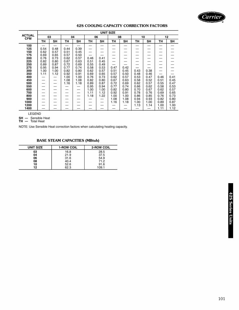
101
42S COOLING CAPACITY CORRECTION FACTORS
LEGEND
NOTE: Use Sensible Heat correction factors when calculating heating capacity.
BASE STEAM CAPACITIES (MBtuh)
ACTUALCFM
UNIT SIZE03 04 06 08 10 12
TH SH TH SH TH SH TH SH TH SH TH SH100 — — — — — — — — — — — —125 0.54 0.48 0.44 0.39 — — — — — — — —150 0.62 0.57 0.51 0.45 — — — — — — — —175 0.69 0.65 0.57 0.50 — — — — — — — —200 0.76 0.73 0.62 0.57 0.46 0.41 — — — — — —225 0.82 0.80 0.67 0.63 0.51 0.45 — — — — — —250 0.89 0.87 0.72 0.69 0.55 0.49 — — — — — —275 0.95 0.94 0.77 0.74 0.58 0.53 0.47 0.42 — — — —300 1.00 1.00 0.82 0.80 0.62 0.57 0.51 0.45 0.43 0.38 — —350 1.11 1.12 0.92 0.91 0.69 0.65 0.57 0.50 0.48 0.46 — —400 — — 1.00 1.00 0.76 0.73 0.62 0.57 0.53 0.47 0.46 0.41450 — — 1.08 1.08 0.82 0.80 0.67 0.63 0.58 0.52 0.51 0.45500 — — 1.16 1.18 0.89 0.87 0.72 0.69 0.62 0.57 0.55 0.47550 — — — — 0.95 0.94 0.77 0.74 0.66 0.62 0.58 0.53600 — — — — 1.00 1.00 0.82 0.80 0.70 0.67 0.62 0.57700 — — — — 1.11 1.12 0.92 0.91 0.78 0.76 0.69 0.65800 — — — — 1.18 1.22 1.00 1.00 0.86 0.85 0.76 0.73900 — — — — — — 1.08 1.08 0.94 0.93 0.82 0.80
1000 — — — — — — 1.16 1.18 1.00 1.00 0.89 0.871200 — — — — — — — — 1.13 1.14 1.00 1.001400 — — — — — — — — — — 1.11 1.12
SH — Sensible HeatTH — Total Heat
UNIT SIZE 1-ROW COIL 2-ROW COIL03 16.8 28.504 21.9 37.506 31.6 54.908 40.4 71.210 52.6 91.612 62.3 109.1
42S
Series U
nits
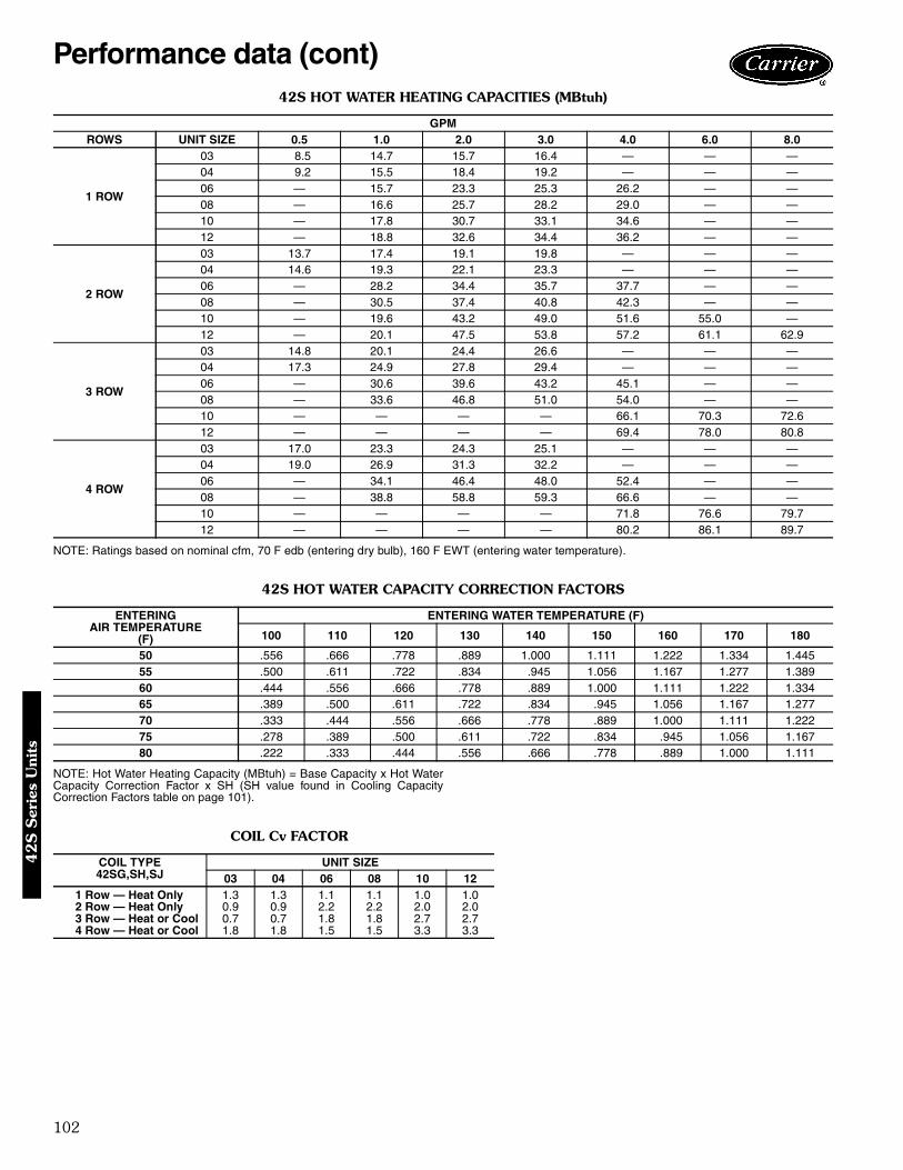
102
42S HOT WATER HEATING CAPACITIES (MBtuh)
NOTE: Ratings based on nominal cfm, 70 F edb (entering dry bulb), 160 F EWT (entering water temperature).
42S HOT WATER CAPACITY CORRECTION FACTORS
NOTE: Hot Water Heating Capacity (MBtuh) = Base Capacity x Hot WaterCapacity Correction Factor x SH (SH value found in Cooling CapacityCorrection Factors table on page 101).
COIL Cv FACTOR
GPMROWS UNIT SIZE 0.5 1.0 2.0 3.0 4.0 6.0 8.0
1 ROW
03 8.5 14.7 15.7 16.4 — — —04 9.2 15.5 18.4 19.2 — — —06 — 15.7 23.3 25.3 26.2 — —08 — 16.6 25.7 28.2 29.0 — —10 — 17.8 30.7 33.1 34.6 — —12 — 18.8 32.6 34.4 36.2 — —
2 ROW
03 13.7 17.4 19.1 19.8 — — —04 14.6 19.3 22.1 23.3 — — —06 — 28.2 34.4 35.7 37.7 — —08 — 30.5 37.4 40.8 42.3 — —10 — 19.6 43.2 49.0 51.6 55.0 —12 — 20.1 47.5 53.8 57.2 61.1 62.9
3 ROW
03 14.8 20.1 24.4 26.6 — — —04 17.3 24.9 27.8 29.4 — — —06 — 30.6 39.6 43.2 45.1 — —08 — 33.6 46.8 51.0 54.0 — —10 — — — — 66.1 70.3 72.612 — — — — 69.4 78.0 80.8
4 ROW
03 17.0 23.3 24.3 25.1 — — —04 19.0 26.9 31.3 32.2 — — —06 — 34.1 46.4 48.0 52.4 — —08 — 38.8 58.8 59.3 66.6 — —10 — — — — 71.8 76.6 79.712 — — — — 80.2 86.1 89.7
ENTERINGAIR TEMPERATURE
(F)
ENTERING WATER TEMPERATURE (F)
100 110 120 130 140 150 160 170 180
50 .556 .666 .778 .889 1.000 1.111 1.222 1.334 1.44555 .500 .611 .722 .834 .945 1.056 1.167 1.277 1.38960 .444 .556 .666 .778 .889 1.000 1.111 1.222 1.33465 .389 .500 .611 .722 .834 .945 1.056 1.167 1.27770 .333 .444 .556 .666 .778 .889 1.000 1.111 1.22275 .278 .389 .500 .611 .722 .834 .945 1.056 1.16780 .222 .333 .444 .556 .666 .778 .889 1.000 1.111
COIL TYPE42SG,SH,SJ
UNIT SIZE03 04 06 08 10 12
1 Row — Heat Only 1.3 1.3 1.1 1.1 1.0 1.02 Row — Heat Only 0.9 0.9 2.2 2.2 2.0 2.03 Row — Heat or Cool 0.7 0.7 1.8 1.8 2.7 2.74 Row — Heat or Cool 1.8 1.8 1.5 1.5 3.3 3.3
Performance data (cont)4
2S
Ser
ies
Uni
ts

103
MAIN RISER PRESSURE DROPS
42S
Series U
nits
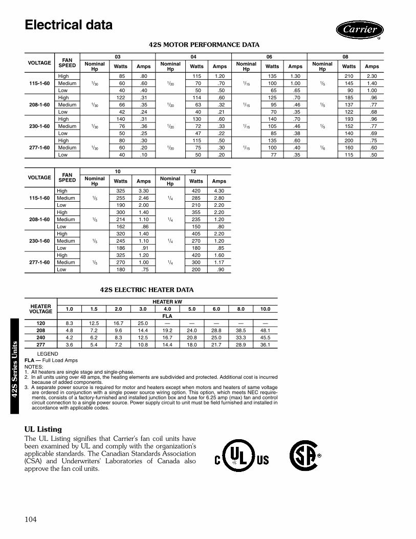
104
42S MOTOR PERFORMANCE DATA
42S ELECTRIC HEATER DATA
LEGENDFLA — Full Load AmpsNOTES:1. All heaters are single stage and single-phase.2. In all units using over 48 amps, the heating elements are subdivided and protected. Additional cost is incurred
because of added components.3. A separate power source is required for motor and heaters except when motors and heaters of same voltage
are ordered in conjunction with a single power source wiring option. This option, which meets NEC require-ments, consists of a factory-furnished and installed junction box and fuse for 6.25 amp (max) fan and controlcircuit connection to a single power source. Power supply circuit to unit must be field furnished and installed inaccordance with applicable codes.
UL ListingThe UL Listing signifies that Carrier's fan coil units havebeen examined by UL and comply with the organization'sapplicable standards. The Canadian Standards Association(CSA) and Underwriters' Laboratories of Canada alsoapprove the fan coil units.
VOLTAGE FANSPEED
03 04 06 08Nominal
Hp Watts Amps NominalHp Watts Amps Nominal
Hp Watts Amps NominalHp Watts Amps
115-1-60High
1/30
85 .801/20
115 1.201/15
135 1.301/5
210 2.30Medium 60 .60 70 .70 100 1.00 145 1.40Low 40 .40 50 .50 65 .65 90 1.00
208-1-60High
1/30
122 .311/20
114 .601/15
125 .701/5
185 .96Medium 66 .35 63 .32 95 .46 137 .77Low 42 .24 40 .21 70 .35 122 .68
230-1-60High
1/30
140 .311/20
130 .601/15
140 .701/5
193 .96Medium 76 .36 72 .33 105 .46 152 .77Low 50 .25 47 .22 85 .38 140 .69
277-1-60High
1/30
80 .301/20
115 .501/15
135 .601/6
200 .75Medium 60 .20 75 .30 100 .40 160 .60Low 40 .10 50 .20 77 .35 115 .50
VOLTAGE FANSPEED
10 12Nominal
Hp Watts Amps NominalHp Watts Amps
115-1-60High
1/5
325 3.301/4
420 4.30Medium 255 2.46 285 2.80Low 190 2.00 210 2.20
208-1-60High
1/5
300 1.401/4
355 2.20Medium 214 1.10 235 1.20Low 162 .86 150 .80
230-1-60High
1/5
320 1.401/4
405 2.20Medium 245 1.10 270 1.20Low 186 .91 180 .85
277-1-60High
1/5
325 1.201/4
420 1.60Medium 270 1.00 300 1.17Low 180 .75 200 .90
HEATERVOLTAGE
HEATER kW1.0 1.5 2.0 3.0 4.0 5.0 6.0 8.0 10.0
FLA120 8.3 12.5 16.7 25.0 — — — — —208 4.8 7.2 9.6 14.4 19.2 24.0 28.8 38.5 48.1240 4.2 6.2 8.3 12.5 16.7 20.8 25.0 33.3 45.5277 3.6 5.4 7.2 10.8 14.4 18.0 21.7 28.9 36.1
Electrical data4
2S
Ser
ies
Uni
ts
105
Fan Coil Unit — Horizontal ModelsHVAC Guide Specifications — 42CSize Range: 200 to 1200 Nominal CfmCarrier Model Numbers:
42CA (Furred-in)42CE (Furred-in with plenum)42CF (Furred-in, high static 400 to 1000 cfm)42CG (Cabinet)42CK (Cabinet, ducted)
Part 1 — General1.01 SYSTEM DESCRIPTION
Horizontal, 2-pipe or 4-pipe (or electric heat), roomfan coil unit with furred-in, above ceiling cabinetfor ducting, or with cabinet for exposed ceilinginstallations.
1.02 QUALITY ASSURANCEUnit shall be tested and certified in accordance withARI Standard 440 and base unit UL certified. (Unitswith special features may not have UL certification.)Each coil shall be factory tested for leakage at350 psig air pressure with coil submerged in water.Insulation and adhesive shall meet NFPA-90Arequirements for flame spread and smoke genera-tion. All equipment wiring shall comply with NECrequirements.
1.03 DELIVERY, STORAGE AND HANDLINGEach unit shall be individually packaged from pointof manufacture. Unit shall be handled and stored inaccordance with the manufacturer’s instructions.
Part 2 — Products2.01 EQUIPMENT
A. General:Factory-assembled, horizontal, blow-thru type fancoil for furred-in, exposed ceiling or ducted installa-tions. Unit shall be complete with water coil(s),fan(s), motor(s), drain pan, and all required wiring,piping, controls and special features.
B. 42CA Base Unit:1. Casing is 18-gage galvanized steel, lined on the
inside with ½ in thick fiberglass Tuf-Skin™ IIinsulation, with a 1 in. long collar for supplyduct connection. NO filter installed in base unit.
2. The drain pan shall be constructed of galva-nized steel extending the entire length andwidth of the coil(s) and shall be pitched fordrainage. The inside surface of the drain panshall be coated with closed-cell fire-retardantfoam insulation. An extension drain pan shallbe provided for installation under factory-provided water valves at the job site.
C. 42CE,CF Furred-in Units:Base 42CA unit with factory-installed plenum sec-tion (not on 42CF unit) and 1-in. fiberglass throw-away filter as shown on equipment drawings. Theplenum shall be bottom or rear air return, shallenclose the fan/motor assemblies, and shall be lined
with ½-in. fiberglass Tuf-Skin II insulation. Unit shallhave a removable panel to provide access to fan/motor assemblies and unit identification label.
D. 42CG Cabinet Units:Base 42CA unit with stamped discharge grille,removable bottom access panel with stampedreturn-air grille, filter rack and 1-in. fiberglass throw-away filter. The panel shall be fastened with slottedhead, positive-locking quarter-turn fasteners. Thecabinet shall be coated with an Arctic White bakedfinish.
E. 42CK Ceiling, Furred-in with 2-in. Telescoping Ceil-ing Panel:Base 42CA unit with full galvanized upper casing,adjustable height, hinged return-air ceiling panel,and 1-in. fiberglass throwaway filter. Panel shall becoated with an Arctic White baked finish.
F. Fans:Direct-driven, double-width fan wheels with forward-curved blades shall be statically and dynamicallybalanced. Scrolls shall be constructed of galvanizedsteel. Fan wheels shall be constructed of galvanizedsteel.
G. Coils:Standard base unit shall be equipped with a 3-row or4-row coil for installation in a 2-pipe system. Addi-tional coil depth and circuiting shall be provided forinstallation in a 4-pipe system as described in theSpecial Features section. All coils shall have ½-in.copper tubes and aluminum fins spacing; Coil finsare mechanical bonded to tube joints. The coppertubes comply with the ASTM B-75. The fin thick-ness is 0.0045-in and tube thickness is 0.016-in. Allcoils are tested with air under water and are suitablefor design working pressures of 250 psig at 220 F.Burst tested at 350 psig.
H. Controls and Safeties:Unit shall be furnished with a 3-speed, 4-positionfan switch on a wall plate for field mounting. Thefan motor(s) shall be equipped with integral auto-matic temperature reset for motor protection.
I. Operating Characteristics:1. A one-coil unit installed in a 2-pipe system shall
be capable of providing heating or cooling asdetermined by the operating mode of the cen-tral water supply system.
2. A double-circuit coil unit installed in a 4-pipesystem shall be capable of providing sequencedheating and cooling.
J. Electrical Requirements:Standard unit shall operate on 120 v, single-phase,60 Hz electric power. All internal wiring shall be inflexible conduit.
K. Motor(s):Fan motors shall be 3-speed, 120 v, single-phase,60 Hz, permanent split capacitor type, with sleeve
Guide specifications — 42C series

106
type bearings and oversized oil reservoirs to ensurelubrication.
L. Special Features:Certain standard features are not applicable whenthe features designated by * are specified. See yourlocal Carrier Sales Offices for amendingspecifications.
* 1. Unit coil(s) shall be equipped with automatic airvents.
* 2. For installation in a 4-pipe system, unit shall beequipped with a 3-row cooling/one-row heat-ing split-circuit coil, a 3-row cooling/2-rowheating split-circuit coil, or a 4-row cooling/one-row heating split-circuit coil as required.Coil connections to be as shown on the equip-ment drawings.
* 3. For installation on a 2-pipe system, units shallbe equipped with a 4-row high capacity coil.
* 4. Fan motor shall be permanent split-capacitortype, 208, 220, 240, or 277-v, single-phase,50 or 60 Hz as specified on the equipmentschedule.
* 5. Unit shall be equipped with electric strip heatersmounted on the entering air side of the watercoil. Heaters shall include high limit cutout withauto reset and contactor. Capacity and voltageshall be as shown on the equipment schedule.When fan motor and electric heater are selectedat the same voltage and connected to a singlepower source, a junction box and fuse shall befactory furnished and installed to protect themotor and control circuit.
* 6. Filter track and cleanable filter shall be installedin the plenum.
7. Extra throwaway or cleanable filters shall be fur-nished for field installation as indicated on theequipment schedule.
* 8. Drain pan shall include a second drain connec-tion located above the main drain connection to
act as an indicator that the main drain isplugged.
9. A hinged, bar type aluminum return-air grillewith filter holder shall be furnished for fieldinstallation (42CA, CE, CF).
*10. Discharge-air grille with double deflection, alu-minum construction with aluminum frame shallbe factory installed as shown on the equipmentschedule. Aluminum grilles shall have a naturalanodized finish (42CG only).
*11. Double-deflection discharge-air grille with steelconstruction shall be factory installed as shownon equipment schedule. Grille shall be paintedto match cabinet (42CG only).
12. Discharge-air grille with double deflection, alu-minum construction shall be furnished for fieldinstallation as shown on equipment schedule.Aluminum grilles shall have a natural anodizedfinish (42CA, CE, CF, CK).
13. Manual stop, gate, balancing, combination bal-ance and stop, ball type, and flow control valvesshall be factory furnished and installed as indi-cated on the equipment drawings.
14. Motorized 2-way and 3-way valves shall be fac-tory wired and assembled with tubes terminat-ing in belled ends or unions for field attachmentto the coil. Valves shall be packaged within unitto prevent shipping damage.
15. Heating and/or cooling wall thermostat shall befactory furnished for field installation.
16. Automatic changeover device(s) shall be factorywired for field installation on the supply piping.
17. Sequenced heating and cooling wall thermostatshall be factory furnished for field installation.
18. Tamper proof fasteners shall be installed on theaccess panel on cabinet models.
19. Unit shall operate on 208, 220, 240, or 277-v,single-phase, 50 or 60 Hz electrical power asspecified on the equipment schedule. All wiringshall be in flexible metal conduit.
Guide specifications — 42C series (cont)

107
Fan Coil Unit — Ducted ModelsHVAC Guide Specifications — 42DSize Range: 600 to 2000 Nominal CfmCarrier Model Numbers:
42DA (Ceiling Furred-in)42DC (Ceiling Furred-in with Plenum)42DD (Vertical with Galvanized Casing)42DE (Ceiling with Galvanized Casing)42DF (Ceiling Exposed Cabinet)
Part 1 — General1.01 SYSTEM DESCRIPTION
Horizontal, 2-pipe or 4-pipe or electric heat fan coilunit for ducted installations; horizontal furred-in orexposed ceiling model, ceiling cabinet, or verticalmodel with galvanized casing for closet or utilityroom installation.
1.02 QUALITY ASSURANCEUnits shall be UL approved, except for 42DF. Allunits shall be CSA approved, including 42DF. Eachcoil shall be factory tested for leakage at 350 psig airpressure with coil submerged in water. Insulationand adhesive shall meet NFPA-90A requirementsfor flame spread and smoke generation. All equip-ment wiring shall comply with NEC requirements.The 42DF model shall be tested and certified inaccordance with ARI Standard 440.
1.03 DELIVERY, STORAGE AND HANDLINGUnit shall be handled and stored in accordance withthe manufacturer’s instructions.
Part 2 — Products2.01 EQUIPMENT
A. General:Factory assembled, horizontal or vertical blow-thruducted fan coil unit. Unit shall be complete withwater coil(s), fan(s), motor(s), drain pan, andall required wiring, piping, controls and specialfeatures.
B. Horizontal, Furred-in Base Unit (42DA):1. Outside panels shall be galvanized steel, lined
on the inside with ½-in. thick fiberglass Tuf-Skin™ II insulation and a 1 in. long collar forsupply duct connection.
2. The drain pan shall be constructed of 18-gagegalvanized steel extending the entire length andwidth of coil(s) and pitched for drainage. Theinside surface of the drain pan shall be coatedwith closed-cell, fire retardant foam. An exten-sion drain pan shall be provided for installationat the jobsite under the factory-furnished elec-tric water valves.
C. Horizontal Base Unit with Plenum for ConcealedInstallation (42DC):Unit shall have a factory-installed, 18-gage galva-nized steel plenum section and 1-in. throwaway fil-ter. The plenum shall be either bottom or rearreturn, lined with ½-in. thick fiberglass Tuf-Skin II
insulation and include a removable panel to provideaccess to the fan/motor assembly.
D. Horizontal, Enclosed Unit for Concealed Installation(42DE):Unit shall be constructed of galvanized steel withremovable panels for access to internal compo-nents. Units have ½-in. fiberglass Tuf-Skin II insula-tion, filter track with 1-in. throwaway filter, 1-in.supply collar, and 2½-in. return-air collar on rear ofunit for duct connection.
E. Horizontal Cabinet Unit for Exposed Installation(42DF):Unit shall be constructed of steel with arctic whitere-coatable baked enamel finish. Cabinet shall belined with ½-in. fiberglass Tuf-Skin II insulation andhave removable bottom access panel. Unit shallinclude hinged bar type return-air grille on rear ofunit with 1-in. throwaway filter and integral doubledeflection supply-air grille.
F. Vertical, Enclosed Unit for Closet Installation(42DD):Unit shall be constructed of galvanized steel with½-in. fiberglass Tuf-Skin II insulation. Unit shallinclude front return-air opening with 1-in. throw-away filter and 1-in. supply-air duct collar.
G. Fans:Direct-driven, double-width fan wheels shall haveforward-curved blades, and be statically and dynami-cally balanced, with scrolls and fans constructed ofgalvanized steel.
H. Coils:Standard base unit shall be equipped with a 4-rowcoil for installation in a 2-pipe system. Additionalcoil depth and circuiting shall be provided for instal-lation in a 4-pipe system as described in the SpecialFeatures section. All coils shall have ½-in. coppertubes and aluminum fins spacing; Coil fins aremechanical bonded to tube joints. The copper tubescomply with the ASTM B-75. The fin thickness is0.0045-in. and tube thickness is 0.016-in. All coilsare tested with air under water and are suitable fordesign working pressures of 250 psig at 220 F.Burst tested at 350 psig.
I. Controls and Safeties:Unit shall be furnished with a 3-speed, 4-positionfan switch on a wall plate for field mounting. Thefan motor(s) shall be equipped with integral, auto-matic reset thermal overload motor protection.
J. Operating Characteristics:A single-circuit coil unit installed in a 2-pipe systemshall be capable of providing heating or cooling asdetermined by the operating mode of the centralwater supply system. A double circuit coil unitinstalled in a 4-pipe system shall be capable of pro-viding sequenced heating and cooling.
Guide specifications — 42D series
108
K. Electrical Requirements:Standard unit shall operate on 115-v, single-phase,60-Hz electric power, and all exposed wiring shall bein a flexible conduit.
L. Motor(s):Fan motors shall be 3-speed permanent split capaci-tor type, 115 volts, with sleeve type bearings andoversized oil reservoirs.
M. Special Features:Certain standard features are not applicable whenthe features designated by * are specified. Seeyour local Carrier Sales Office for amendingspecifications.
* 1. Unit Coil(s) shall be equipped with automatic airvents.
* 2. Unit shall be equipped with a high-capacity6-row coil for installation in a 2-pipe chilledwater system or DX system.
* 3. For installation in a 4-pipe chilled water systemor DX system, unit shall be equipped with eithera 4-row cooling/one-row heating split circuit,or a 4/2 split circuit or a 6/1 split circuit(except 42DD) as required.
* 4. Fan motor(s) shall be permanent split capacitortype, 208, 230, or 277 volts for low-staticapplications (42DF) or 208, 230 or 277 voltsfor high-static applications (42DA, DC, DD,and DE). 220-volt fan motor shall be availablefor 50 Hz applications.
* 5. Electric Heat:a. Unit shall be equipped with electric resis-
tance strip heaters mounted on the enteringair side of the water coil.
b. Heaters shall include automatic reset highlimit cutout, contactor, factory-furnishedjunction box and fuse to protect the motor.
c. Heaters shall be single-stage, single-phase,120, 208, 220, 240 or 277 volts, for 50 Hz
or 60 Hz applications. Capacity shall be asshown on the equipment schedule.
d. Control circuit for single power source con-nection is available and must be used whenmotors and heaters are of the same voltage.
* 6. Filter track and cleanable filter shall be installedin the plenum (42DC, DD, and DE only).
7. Extra throwaway or cleanable filters shall be fur-nished for field installation as indicated on theequipment schedule.
8. Drain pan shall include a second drain connec-tion located above the main drain connection toact as an indicator that the main drain isplugged.
9. Removable drain pan extension (drip lip) shallbe available for field installation under electricwater valves.
10. Six-in. diameter outside air opening with ductcollar shall be provided to duct outside ventila-tion air to unit, with or without manual outdoorair damper.
11. Gate, balancing and combination balance andstop (ball) and flow control valves shall be fac-tory furnished and installed as indicated on theequipment drawings.
12. Motorized 2-way and 3-way valves shall bewired to the unit. In order to prevent shippingdamage, they shall be factory assembled in thevalve package. The valve packages shall termi-nate with belled ends or unions for field attach-ment to the coil.
13. Heating and/or cooling thermostat (SPDT)shall be factory furnished for field installation(2-pipe system).
14. Automatic changeover device(s) shall be factorywired for field installation on supply piping(2-pipe system).
15. Sequenced heating and cooling wall thermostatshall be factory furnished for field installation(4-pipe system).
Guide specifications — 42D series (cont)
109
Fan Coil Unit — Vertical Stack ModelsHVAC Guide Specifications — 42SSize Range: 300 to 1200 Nominal CfmCarrier Model Numbers:
42SGA (Furred-in)42SHA (Cabinet)42SJA (Furred-in, Back-to-Back)
Part 1 — General1.01 SYSTEM DESCRIPTION
Stack fan coil units, 2-pipe, 4-pipe or electric heatfor furred-in or exposed cabinets that are floormounted in multi-story buildings.
1.02 QUALITY ASSURANCEUnits shall be tested and certified in accordance withARI standard 440, latest edition. All units shall beUL and CSA approved. Each coil shall be factorytested for leakage at 350 psig air pressure with coilsubmerged in water. Insulation and adhesive shallmeet NFPA-90A requirements for flame spread andsmoke generation. All equipment wiring shall com-ply with NEC requirements.
1.03 DELIVERY, STORAGE AND HANDLINGUnit shall be handled and stored in accordance withthe manufacturer’s instructions.
Part 2 — Products2.01 EQUIPMENT
A. General:Factory assembled, stack fan coil units. Units arecomplete with water coil(s), fan(s), motor(s), drainpan, and all required wiring, piping, controls, andspecial features.
B. Cabinet Stack Unit (42SH):Outside panels are made of 18-gage galvanized steelcoated with baked-on enamel finish and are fabri-cated with no exposed fasteners. The interior sur-faces shall be lined with ½-in. thick fiberglassTuf-Skin™ II insulation. The standard cabinet unithas factory-installed double deflection dischargegrille(s) and stamped supply grille. Controls are fac-tory wired and mounted in small access panel atfront of unit.
C. Furred-In Stack Unit (42SG):The unit shall be constructed of 18-gage galvanizedsteel frame and 18-gage galvanized steel back panel.The fan coil is open or enclosed for furred-in instal-lation. These units are designed to have the wall-board applied directly to the unit surface and allopenings have standard ½-in. thick fiberglass Tuf-Skin II insulation. Units have double deflection alu-minum discharge grille(s) and painted, stamped(standard) or bar-type aluminum (optional) return-airgrille panel. Removable return-air grille providesaccess to all internal piping and wiring. Controls areprovided with a quick disconnect plug for field-mounting on front of unit.
D. Back-To-Back Furred-In Stack Units (42SJ):The open unit shall be constructed of 18-gage galva-nized steel frame and 18-gage galvanized steel backpanel. These units are similar to the 42SG but areactually two completely separate units contained inone cabinet that share a common set of risers.These units are designed to have the wallboarddirectly applied to the unit surface and openingshave standard ½-in. drywall flanges. The interiorsurfaces shall be lined with ½-in. thick fiberglass Tuf-Skin II insulation. Units have double deflection alu-minum supply grille(s) and painted, stamped (stan-dard) or bar-type aluminum (optional) return-airgrille panel. Removable return-air grille providesaccess to all internal piping and wiring. Controls areprovided with a quick disconnect plug for field-mounting on front of unit.
E. Drain Pan:Drain pan shall be formed of 18-gage steel and shallbe coated inside with fire-retardant closed-cell foaminsulation. Water never touches the metal pan elimi-nating the possibility of corrosion. The drain is fac-tory piped to the drain riser that has a removable“P-trap” allowing easy cleaning.
F. Filter:A filter track complete with 1-in. fiberglass throw-away filter shall be installed in the unit. Optional per-manent filters are available.
G. Fan:1. Centrifugal fan shall be directly-driven by an
electric motor.2. Fan wheel shall be double-width type with
forward-curved blades and shall be statically anddynamically balanced.
3. Fan wheel and scroll shall be constructed of gal-vanized steel.
H. Coil:1. Standard base unit shall be equipped with a
3-row for installation in a 2-pipe system. Addi-tional coil depth and circuiting shall be providedfor installation in a 4-pipe system as describedin the Special Features section.
2. All coils shall have ½-in. copper tubes and alu-minum fins spacing; Coil fins are mechanicalbonded to tube joints. The copper tubes complywith the ASTM B-75. The fin thickness is0.0045-in. and tube thickness is 0.016-in. Allcoils are tested with air under water and aresuitable for design working pressures of250 psig at 220 F. Burst tested at 350 psig.
3. Coil shall be equipped with a manual air ventand shall be piped to supply and returnrisers with valves as specified on the equipmentdrawings.
4. Piping between coil and risers shall includeloops to compensate for maximum riser expan-sion and contraction of 11/2 inches.
Guide specifications — 42S series
110
I. Risers:1. Standard factory-furnished and installed risers
shall be 104 in. long with 3-in. belled ends atthe top such that only one sweat connectionshall be required at each floor to join one riserto another.
2. Risers shall be Type M copper insulated with1/2-in. thick synthetic rubber.
3. Standard supply and return risers shall be11/4 in. diameter, drain riser shall be 1 in. diam-eter.
J. Valves:The factory furnished and installed piping shallinclude two ball valves and one 2-way motorizedvalve. The ball valves shall be rated at 150 psig.
K. Controls and Safeties:1. Controls:
a. Standard controls for a 2-pipe system shallconsist of a 3-speed fan switch, heating/cooling thermostat (SPDT) and an automaticchangeover device.
b. Unit controls shall be mounted behind theaccess door on the return air panel.
2. Safeties:Unit fan motor shall be equipped with integralmotor protection.
L. Operating Characteristics:1. A unit with a conventional coil, installed in a
2-pipe system, shall be capable of providingheating or cooling as determined by the operat-ing mode of the central water supply system.
2. A unit with a row-split coil, installed in a 4-pipesystem, shall be capable of providing sequencedheating and cooling.
M. Electrical RequirementsStandard unit shall operate on 115-v, single phase,60-Hz electrical power supply.
N. Motor:1. Fan motor shall be 3-speed, 115-v, single
phase, 60-Hz, permanent split capacitor type,factory mounted on the blower housing.
2. Bearings shall be of the sleeve type with oiltubes and oversized oil reservoir to assurepositive lubrication and minimum servicerequirements.
O. Special Features:Certain standard features are not applicable whenthe features designated by * are specified.
* 1. Unit coil shall be equipped with automatic airvents.
* 2. Unit shall be equipped with a 4-row coil forinstallation in a 2-pipe system.
* 3. For installation in a 4-pipe system, unit shall beequipped with:a. A 3/1, 3/2 or 4/1 row-split coil, as shown
on equipment drawings for cooling andheating.
b. Two each 11/4 in. diameter supply andreturn risers and one 1 in. diameter drainriser.
c. Two gate valves, 2 combination balance andstop valves and two 2-way motorized valves.The gate and combination valves shall berated at 150 psig.
d. Three-speed fan switch and a sequencedheating and cooling thermostat.
* 4. Unit shall be equipped with 3-way motorizedvalves.
* 5. Supply and return risers shall be 1 in., 11/2 in.,2 in. or 21/2 in. diameter as shown on theequipment drawings.
* 6. Floor-to-floor height of risers shall be as speci-fied on the equipment drawings.
* 7. Supply and return risers shall be Type Lcopper.
* 8. Drain riser shall be Type DWV copper.* 9. Insulation on risers shall be 3/4-in. thick syn-
thetic rubber.*10. Unit shall be equipped with a separate reverse-
return riser with size as shown on the equip-ment drawings.
11. Automatic balancing check valve(s) shall befactory installed as shown on the equipmentdrawings.
*12. Motor shall be 3-speed, single phase, 60 Hzpermanent split capacitor type for 208, 230 or277 volts or 50 Hz permanent split capacitortype for 220 volts.
*13. Double-deflection supply grille(s) shall be fin-ished with white primer or Arctic White paint.Additional double-deflection supply grille(s) shallbe furnished for field installation.
14. Ceiling skirts for exposed stack units shall beprovided for field trim and installation.
15. A fresh-air opening shall be provided as shownon the equipment drawings.
*16. One-in. thick cleanable filters shall be installedin the filter track.
17. Unit shall be equipped with nichrome wire elec-tric strip heaters for total or auxiliary electricheat as specified on the equipment schedule.a. Heaters shall be protected by an automatic
reset safety cutout switch and a fusible link.b. Heater capacity shall be as specified on the
equipment schedule.c. Heaters shall be single phase, 60 Hz for
120, 208, 240 or 277 volts as specified onthe equipment schedule.
Guide specifications — 42S series (cont)
111
*d. For total electric heat, unit controls shallinclude a sequenced heating and coolingthermostat in lieu of the heating/coolingthermostat and automatic changeoverdevice.
e. For auxiliary electric heat, unit controls shallinclude 2 additional automatic changeoverdevices. A junction box and fuse shall befactory-furnished and installed to protect themotor and control circuit when electricheaters are installed in a unit with a singlepower source.
18. Fused or unfused disconnect switch shall beprovided for field installation. Switch shall besuitable for single phase, 60 Hz service for 115,208, 240 or 277 volts as specified on theequipment schedule.

112
Fan Coil Unit — Vertical ModelsHVAC Guide Specifications — 42VSize Range: 200 to 1200 Nominal CfmCarrier Model Numbers:
42VA (Furred-in)42VB (Cabinet)42VC (Furred-in, low boy, 200 to 600 cfm)42VE (Cabinet, low boy, 200 to 600 cfm)42VF (Cabinet, slant top)42VG (Furred-in, wall, 150 and 300 cfm)
Part 1 — General1.01 SYSTEM DESCRIPTION
Vertical, 2-pipe or 4-pipe, or electric heat, room fancoil unit for furred-in, or cabinet floor mountedinstallation. (42VC and VE are low profile units.)
1.02 QUALITY ASSURANCEUnit shall be tested and certified in accordance withARI Standard 440 and base unit UL certified. (Unitswith special features may not have UL certification.)Each coil shall be factory tested for leakage at300 psig air pressure with coil submerged in water.Insulation and adhesive shall meet NFPA-90Arequirements for flame spread and smokegeneration.
1.03 DELIVERY, STORAGE AND HANDLINGEach unit shall be individually packaged from pointof manufacture. Unit shall be handled and stored inaccordance with the manufacturer’s instructions.
Part 2 — Products2.01 EQUIPMENT
A. General:Factory-assembled, vertical, blow-thru type floormounted fan coil for furred-in or exposed installa-tions. Unit shall be complete with water coil, fan(s),motor(s), drain pan, and all required wiring, piping,controls and special features.
B. 42VA, VC Base Unit:1. Outside panels are made of 18-gage galvanized
steel. Lined on the inside with ½ in. thick fiber-glass Tuf-Skin™ II insulation, with a 1 in. longcollar for top supply duct connection. Unitsshall be supplied with a 1-in. fiberglass throw-away filter.
2. The drain pan shall be constructed of 18-gagegalvanized steel extending the entire length andwidth of the coil(s) and pitched for drainage.The inside surface of the drain pan shall becoated with closed cell fire retardant foam insu-lation. An extension drain pan shall be providedfor installation under the water valves at the job-site.
C. 42VB, VE, VF Cabinet Models:1. Cabinet models shall be coated with an Arctic
White baked finish, and include a 1-in. fiber-glass throwaway filter.
2. Cabinet models shall be free standing with 2access doors. A stamped supply-air grille shallbe included in the top of the cabinet. (Overallcabinet height shall not exceed 141/2 in. on lowprofile 42VE unit.)
3. The 42VF top panel shall slope down fromback to front at an angle of 25 degrees. Stan-dard stamped grille shall provide a dischargeinto the room at a nominal 67 degrees from thevertical.
D. 42VG Furred-In Model:1. Cabinet shall be fabricated of 18-gage galva-
nized steel with ½ in. thick fiberglass insulation.Cabinet shall be coated with baked enamel fin-ish. Removable front panel shall provide serviceaccess and shall include die-formed supply- andreturn-air grilles.
2. Combination condensate pan and fan deckshall be insulated with closed-cell fire-retardantfoam.
E. Fans:Direct-driven, double-width fan wheels shall haveforward-curved blades and shall be statically anddynamically balanced. Scrolls and fan wheels shallbe constructed of galvanized steel.
F. Coils:Standard base unit shall be equipped with a 3-row(42VA, VB, VF units) or 2-row coil (42VC, VE, VGunits) for installation in a 2-pipe system. Additionalcoil depth and circuiting shall be provided for instal-lation in a 4-pipe system as described in the SpecialFeatures section. All coils shall have ½ in. coppertubes and aluminum fins spacing; Coil fins aremechanical bonded to tube joints. The copper tubescomply with the ASTM B-75. The fin thickness is0.0045 in and tube thickness is 0.016 in. All coilsare tested with air under water and are suitable fordesign working pressures of 250 psig at 220 F.Burst tested at 350 psig.
G. Controls and Safeties:Unit shall be furnished with a 3-speed, 4-positionfan switch on a wall plate for field mounting onfurred-in units. Cabinet units shall be furnished witha factory-installed 3-speed, 4-position fan switch.Internal wiring from motor and valves shall be inflexible metal conduit, terminating in the junctionbox.
H. Operating Characteristics:1. A one-coil unit installed in a 2-pipe system shall
be capable of providing heating and cooling asdetermined by the operating mode of the cen-tral water supply system.
2. A double-circuit coil unit installed with a 4-pipesystem shall be capable of providing sequencedheating and cooling.
Guide specifications — 42V series
113
I. Electrical Requirements:Standard unit shall operate on 120 v, single-phase,60 Hz electric power. All internal wiring shall be inflexible conduit.
J. Motor(s):Fan motor(s) shall be 3-speed, 120 v, single-phase,60 Hz, permanent split capacitor type with sleevetype bearings and oversized oil reservoirs to ensurelubrication. Motors shall have integral automatictemperature reset for motor protection.
K. Special Features:Certain standard features are not applicable whenthe features designated by * are specified. Seeyour local Carrier Sales Office for amendingspecifications.
* 1. Unit coil(s) shall be equipped with automatic airvents.
* 2. For installation in a 2-pipe system, unit shall beequipped with a high-capacity 4-row coil(42VA,VB,VF units) or a high-capacity 3-rowcoil (42VC,VE).
* 3. For installation in a 4-pipe system, 42VA,VB,VF units shall be equipped with a 3-rowcooling/one-row heating split-circuit coil, a3-row cooling/2-row heating split-circuit coil ora 4-row cooling/one-row heating split-circuitcoil as required. The 42VC,VE units shall beequipped with a 2-row cooling/one-row heat-ing split-circuit coil.
* 4. Fan motor shall be permanent split-capacitortype, 208, 220, 240, or 277-v, single-phase,50 or 60 Hz as specified on the equipmentschedule.
* 5. Unit shall be equipped with electric resistancesheath type heaters mounted on the leaving airside of the water coil. Heaters shall include highlimit cutout with auto reset and contactor.Capacity and voltage shall be as shown on theequipment schedule. When fan motor and elec-tric heater are selected at the same voltage andconnected to a single power source, a junctionbox and fuse shall be factory furnished andinstalled to protect the motor and control cir-cuit. Unit height on 42VC and VE shall beincreased by 2 in. to accommodate heaters.
* 6. Cleanable filter shall be factory installed in thefilter track.
7. Extra throwaway or cleanable filters shall be fur-nished for field installation as indicated on theequipment schedule.
* 8. Leveling legs shall be factory installed on theunit and permit a maximum adjustment of3/4 inch.
9. Switch box complete with switch shall be fac-tory installed on the unit.
10. Discharge-air grille with double deflectionaluminum construction as shown on the
equipment schedule shall be furnished for fieldinstallation (42VA,VC units).
11. Discharge-air grille with double deflection steelor aluminum construction shall be shipped in-stalled in the unit. (42VB,VF,VE units). Steelgrilles shall be painted to match cabinet. Alumi-num grilles shall be a natural anodized finish.
12. Reverse-stamped grille (42VB,VF units) shallprovide a discharge into the room at a nominal23 degrees from vertical.
13. Stamped type aluminum return-air grille with fil-ter holder shall be furnished for field installa-tion. (Not available for VG unit.)
14. Manual stop, gate, balancing, combination bal-ance and stop (ball type), and flow controlvalves shall be factory furnished and installed asindicated on the equipment drawings.
15. Motorized 2-way and 3-way valves shall be fac-tory assembled and wired to unit with tubes ter-minating in belled ends or unions for fieldattachment to the coil. Valves shall be packagedwithin the unit to prevent shipping damage.
16. Heating and/or cooling wall thermostat shall befactory furnished for field installation.
17. Heating and/or cooling thermostat shall be fac-tory wired and installed.
18. Automatic changeover device(s) shall be factorywired for field installation on the supply piping.
19. Sequenced heating and cooling wall thermostatshall be factory furnished for field installation.
20. Sequenced heating and cooling thermostat shallbe factory wired and installed.
*21. Tamper proof fasteners shall be installed onfront panel and access doors on cabinetmodels.
*22. Cabinet shall be painted with the color specifiedon the equipment schedule.
*23. Factory-installed outside air damper shall bemanually adjustable through the return airopening or shall be arranged for remote manualadjustment, complete with linkage and electricmotor to open damper when fan is on. Or, unitshall have a 3/16-in. shaft extending outside theunit for installation of a field-supplied damper(42VA,VB,VF).
24. Wall panels, painted with specified color, shallbe furnished for top discharge or front dis-charge recessed unit (42VA only).
25. Unit shall operate on 208, 220, 240, or 277-v,single-phase, 50 or 60 Hz electrical power asspecified on the equipment schedule. All wiringshall be in flexible conduit.
26. Outside air wall boxes for field installation.

Manufacturer reserves the right to discontinue, or change at any time, specifications or designs without notice and without incurring obligations.New Pg 114 Catalog No. 524-234 Printed in U.S.A. PC 201 Form 42-2PD
Replaces: 42-1PDBook 3Tab 7a
Carrier Corporation • Syracuse, New York 13221 2-04
Book 4 4 4Tab 4FC1 4FC2 4FC3
42CA section 27-6642CE section 27-6642CF section 27-6642CG section 27-6642CK section 27-6642DA section 67-8942DC section 67-8942DD section 67-8942DE section 67-8942DF section 67-8942SG section 90-10442SH section 90-10442SJ section 90-10442VA section 27-6642VB section 27-6642VC section 27-6642VE section 27-6642VF section 27-6642VG section 27-66Air delivery42C 52-5642D 81-8342S 9842V 57-59
Application data 13-25ARI rating data42C 2842D 6742S 9042V 28
Arrangements, 42S 15Automatic changeover 12Certifications and listings 28, 67, 90Coil connections 20, 44-46, 74, 75Controls 10-12Selection guide 10Remote-mounted 11Unit-mounted 11, 12
Cooling capacities42C 48, 4942D 77-8042S 99, 10042V 48-51
Cv factor 22, 63, 86, 102DimensionsAccessories42C 43-4742D 74-7642S 95-9742V 43-47
Base unit42C 32-3642D 69-7342S 92-9442V 37-42
Direct expansion42C 6042D 8542V 61
Electric heaters 10, 24, 25, 64, 87, 104
Electrical data42C 64-6642D 87-8942S 10442V 64-66
Features/Benefits 1-6Filters42C 3142D 6842S 9142V 31
Guide specifications42C 105, 10642D 107, 10842S 109-11142V 112, 113
Heating capacitiesElectric42C 2542D 2542S 2542V 25
Hot water42C 6242D 8642S 10242V 62
Steam42C 6342D 8642S 10142V 63
Isolation valves 20Model number nomenclature42C 2742D 6742S 9042V 27
Motor data42C 64, 6542D 88, 8942S 10442V 65, 66
Options and accessories 7-9Outside air damper 43Panel combinations 7Performance data42C 48-6342D 77-8642S 98-10342V 48-63
Physical data42C 31-4242D 68-7342S 91-9442V 31-42
Piping 14, 16-19Return air grilles 47, 75Risers 8, 15, 103Selection procedure 26
Service fittings 20Shipping weights42C 3142D 6842S 9142V 31
Sound data42C 2942D 6842S 9142V 30
Strainer 18, 20Supply grilles 47, 75Thermostat 11, 12Valve package arrangements 21Wall boxes 47Wall panels 47, 95-97Water flow balancingComponents 20
Index
Related Documents