11 Pneumatic Fuzzy Controller Simulation vs Practical Results for Flexible Manipulator Juan Manuel Ramos-Arreguin 1 , Jesus Carlos Pedraza-Ortega 2 , Efren Gorrostieta-Hurtado 2 , Rene de Jesus Romero-Troncoso 3 , Jose Emilio Vargas-Soto 4 and Francisco Hernandez-Hernandez 1 1 Universidad Tecnológica de San Juan del Río, 2 Universidad Autónoma de Querétaro, 3 Universidad de Guanajuato, 4 Universidad Anáhuac del Sur, México 1. Introduction The flexible manipulators have many industrial applications; but most of the reported works are using electrical or hydraulic actuators. These actuators have a linear behaviour and the control is easier than pneumatic actuators; but the pneumatic position control is a highly non linear problem, due to the air compressibility behaviour and internal friction (Moore & Pu, 1993). Because of these conditions, there are certain difficulties in pneumatics cylinder control design. The main disadvantage of electrical actuators is the low power- weight rate, the high current related with its load and it is heavy. The hydraulic actuators are not ecological, needs hydraulic oil and return lines to the pump is needed. By the other hand, the pneumatic actuators are clean, economy, light, faster, have a great power-weight rate and return lines are not needed. However, pneumatic actuators are not used into flexible manipulators developed due to their highly non linear behaviour. It is important to note that research lines; such as pneumatic control, embedded systems and flexible manipulators, are used in separate way. As a matter of fact, most of manipulators robots use electric or hydraulic actuators; however, the pneumatic actuators are being used in recent years (Ramos at al, 2006a; Ramos et al, 2006b) to control a flexible manipulator arm. This is the beginning of a project which involves the use of a pneumatic cylinder to control a flexible manipulator robot. Our first approach is to use one degree of freedom, but the main goal is to have a two degree of freedom flexible manipulator. Several pneumatic controllers had been developed; for example, the Model Reference Adaptive Control, MRAC (Suarez & Luis, 2005); however, the pneumatic model used for the control design, have the next considerations; a lineal actuator, a lineal valve, without damping systems at the sides, ideal gas, adiabatic changes and constant viscous friction. Other works have been focused in friction parameter identification techniques of cylinder pneumatic (Wang & Wang, 2004), dynamic modelling and simulation (Jozsef & Claude,

Welcome message from author
This document is posted to help you gain knowledge. Please leave a comment to let me know what you think about it! Share it to your friends and learn new things together.
Transcript
11
Pneumatic Fuzzy Controller Simulation vs Practical Results for Flexible Manipulator
Juan Manuel Ramos-Arreguin1, Jesus Carlos Pedraza-Ortega2, Efren Gorrostieta-Hurtado2, Rene de Jesus Romero-Troncoso3,
Jose Emilio Vargas-Soto4 and Francisco Hernandez-Hernandez1 1Universidad Tecnológica de San Juan del Río,
2Universidad Autónoma de Querétaro, 3Universidad de Guanajuato,
4Universidad Anáhuac del Sur, México
1. Introduction The flexible manipulators have many industrial applications; but most of the reported works are using electrical or hydraulic actuators. These actuators have a linear behaviour and the control is easier than pneumatic actuators; but the pneumatic position control is a highly non linear problem, due to the air compressibility behaviour and internal friction (Moore & Pu, 1993). Because of these conditions, there are certain difficulties in pneumatics cylinder control design. The main disadvantage of electrical actuators is the low power-weight rate, the high current related with its load and it is heavy. The hydraulic actuators are not ecological, needs hydraulic oil and return lines to the pump is needed. By the other hand, the pneumatic actuators are clean, economy, light, faster, have a great power-weight rate and return lines are not needed. However, pneumatic actuators are not used into flexible manipulators developed due to their highly non linear behaviour. It is important to note that research lines; such as pneumatic control, embedded systems and flexible manipulators, are used in separate way. As a matter of fact, most of manipulators robots use electric or hydraulic actuators; however, the pneumatic actuators are being used in recent years (Ramos at al, 2006a; Ramos et al, 2006b) to control a flexible manipulator arm. This is the beginning of a project which involves the use of a pneumatic cylinder to control a flexible manipulator robot. Our first approach is to use one degree of freedom, but the main goal is to have a two degree of freedom flexible manipulator. Several pneumatic controllers had been developed; for example, the Model Reference Adaptive Control, MRAC (Suarez & Luis, 2005); however, the pneumatic model used for the control design, have the next considerations; a lineal actuator, a lineal valve, without damping systems at the sides, ideal gas, adiabatic changes and constant viscous friction. Other works have been focused in friction parameter identification techniques of cylinder pneumatic (Wang & Wang, 2004), dynamic modelling and simulation (Jozsef & Claude,
Automation and Robotics
192
2003), analytic and experimental research (Henri & Hollerbach, 1998) and the development of robotic hands using cylinder pneumatics. Flexible manipulators can be used only under two conditions: a) when the robot weight must be minimized, and b) when the collisions in the work space need to be avoided (Feliu et al, 2001). The modelling of flexible manipulators has been developed almost 35 years ago (Mirro, 1972; Whitney et al, 1974), where, almost in all cases, they used electric or hydraulic actuators, and pneumatic cylinders are discouraged due to their non linear behavior. Pneumatic control started in 1968 with Burrows (1968), and recent works are focused mainly with adaptive control methods (Suarez & Luis, 2005; Quiles et al, 2004), some of them use a computer to implement the control (Burbano et al, 2003). Other researches are focused on mechanical system modelling using pneumatic actuators (Perez, 2003), from these kind of works, a Flexible Manipulator Model with pneumatic cylinder -called Thermo-Mechanical model- was developed, then the mechanical system is involved to give the movement for the flexible arm (Kiyama & Vargas, 2004). By other hand, electric actuators are used in the development of flexible manipulators (Feliu & Garcia, 2001), where the motor speed is considered for the control implementation along with the motor effects and the mechanical structure. In our prototype we are using a flexible manipulator robot with a pneumatic actuator, where the damping systems in both sides and the mechanical dynamics for control are considered. The full Thermo-Mechanical model is used as a starting point, later it is simplified and the results are used for the control development. One contribution of this work is the position control of a flexible manipulator using a pneumatic actuator and a simplified Thermo-Mechanical model (Ramos et al, 2006). The simplified Thermo-Mechanical model of pneumatic actuators allows us to predict its behavior, considering the air compressibility effects, internal friction forces, damping effects in both extremes of the cylinder, massic flow and energy conservation; also, gives us the instant pressure that depends on the rod position. From the engineering control point of view, this model let us predict the variable behavior, involved in the physical process, and can be used for control purposes. This chapter is important, because the innovation of this work is the application of three research lines to obtain a flexible manipulator light, ecological and fast with great power-weight rate. The contribution of this chapter is the reported behaviour of the one-link flexible manipulator with pneumatic actuator with practical control results. Simulations of several controllers have been reported to learn about the pneumatic manipulator behaviour with one-link. The simulation and practical results are discussed. Later, the graphical simulation is important, because let us to obtain the control parameters in few time, and learn about the pneumatic manipulator behaviour before implementation. Finally, the control algorithm is implemented in Matlab language, and digital interfaces are implemented into field programmable gate array (FPGA), obtaining an embedded digital system with serial communication (RS232) protocol. The control algorithm implemented is a PD controller and results are compared with Fuzzy-Controller simulation results.
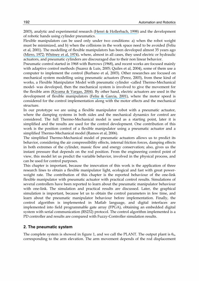
2. The pneumatic system The complete system is showed in figure 1, and we call the PLANT. The output plant is θ6, corresponding to the arm elevation. The arm movement depends of the rod displacement
Pneumatic Fuzzy Controller Simulation vs Practical Results for Flexible Manipulator
193
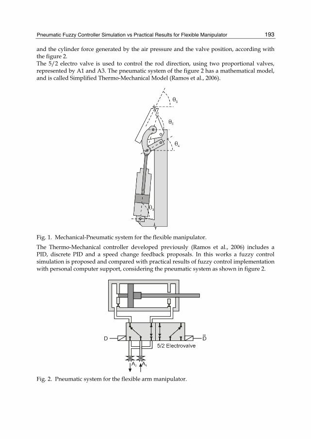
and the cylinder force generated by the air pressure and the valve position, according with the figure 2. The 5/2 electro valve is used to control the rod direction, using two proportional valves, represented by A1 and A3. The pneumatic system of the figure 2 has a mathematical model, and is called Simplified Thermo-Mechanical Model (Ramos et al., 2006).
Fig. 1. Mechanical-Pneumatic system for the flexible manipulator.
The Thermo-Mechanical controller developed previously (Ramos et al., 2006) includes a PID, discrete PID and a speed change feedback proposals. In this works a fuzzy control simulation is proposed and compared with practical results of fuzzy control implementation with personal computer support, considering the pneumatic system as shown in figure 2.
Fig. 2. Pneumatic system for the flexible arm manipulator.
Automation and Robotics
194
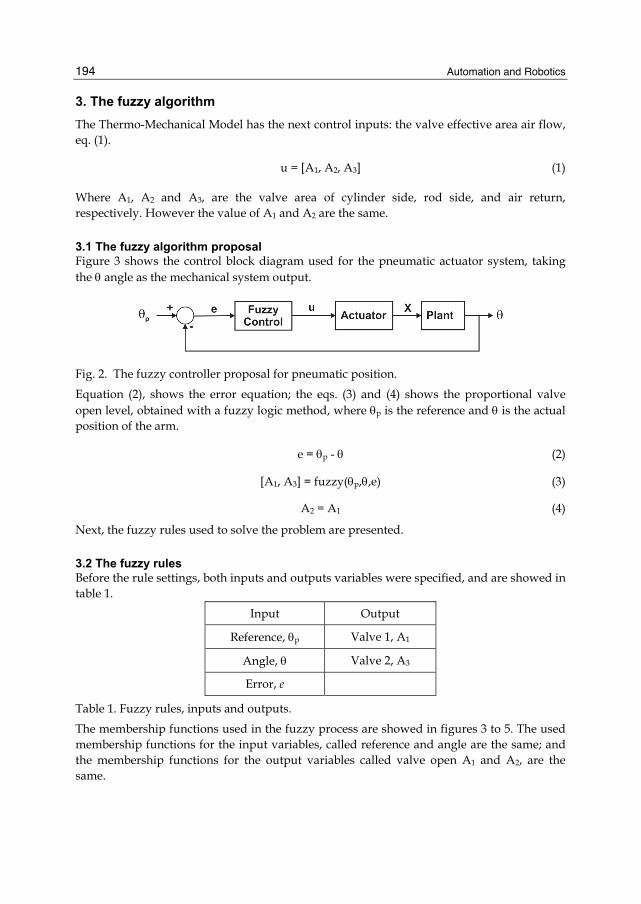
3. The fuzzy algorithm The Thermo-Mechanical Model has the next control inputs: the valve effective area air flow, eq. (1).
u = [A1, A2, A3] (1)
Where A1, A2 and A3, are the valve area of cylinder side, rod side, and air return, respectively. However the value of A1 and A2 are the same.
3.1 The fuzzy algorithm proposal Figure 3 shows the control block diagram used for the pneumatic actuator system, taking the θ angle as the mechanical system output.
Fig. 2. The fuzzy controller proposal for pneumatic position.
Equation (2), shows the error equation; the eqs. (3) and (4) shows the proportional valve open level, obtained with a fuzzy logic method, where θp is the reference and θ is the actual position of the arm.
e = θp - θ (2)
[A1, A3] = fuzzy(θp,θ,e) (3)
A2 = A1 (4)
Next, the fuzzy rules used to solve the problem are presented.
3.2 The fuzzy rules Before the rule settings, both inputs and outputs variables were specified, and are showed in table 1.
Input Output
Reference, θp Valve 1, A1
Angle, θ Valve 2, A3
Error, e
Table 1. Fuzzy rules, inputs and outputs.
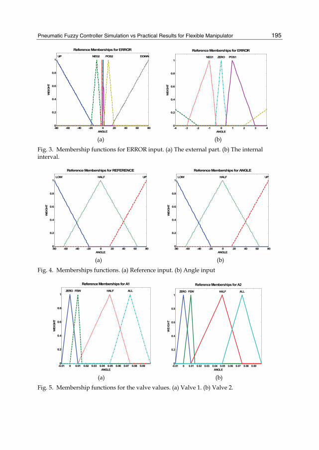
The membership functions used in the fuzzy process are showed in figures 3 to 5. The used membership functions for the input variables, called reference and angle are the same; and the membership functions for the output variables called valve open A1 and A2, are the same.
Pneumatic Fuzzy Controller Simulation vs Practical Results for Flexible Manipulator
195
-80 -60 -40 -20 0 20 40 60 800
0.2
0.4
0.6
0.8
1
Reference Memberships for ERRORW
EIG
HT
ANGLE
UP NEG2 POS2 DOWN
-4 -3 -2 -1 0 1 2 3 40
0.2
0.4
0.6
0.8
1
Reference Memberships for ERROR
WE
IGHT
ANGLE
NEG1 ZERO POS1
(a) (b)
Fig. 3. Membership functions for ERROR input. (a) The external part. (b) The internal interval.
-80 -60 -40 -20 0 20 40 60 800
0.2
0.4
0.6
0.8
1
Reference Memberships for REFERENCE
WEI
GHT
ANGLE
LOW HALF UP
(a)
-80 -60 -40 -20 0 20 40 60 800
0.2
0.4
0.6
0.8
1
Reference Memberships for ANGLEW
EIG
HT
ANGLE
LOW HALF UP
(b)
Fig. 4. Memberships functions. (a) Reference input. (b) Angle input
-0.01 0 0.01 0.02 0.03 0.04 0.05 0.06 0.07 0.08 0.090
0.2
0.4
0.6
0.8
1
Reference Memberships for A1
WEI
GH
T
ANGLE
ZERO FEW HALF ALL
-0.01 0 0.01 0.02 0.03 0.04 0.05 0.06 0.07 0.08 0.090
0.2
0.4
0.6
0.8
1
Reference Memberships for A2
WEI
GH
T
ANGLE
ZERO FEW HALF ALL
(a) (b) Fig. 5. Membership functions for the valve values. (a) Valve 1. (b) Valve 2.
Automation and Robotics
196
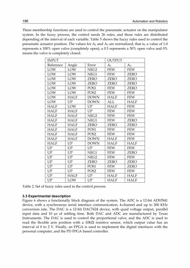
These membership functions are used to control the pneumatic actuator on the manipulator system. In the fuzzy process, the control needs 26 rules, and those rules are distributed depending of the interval of each variable. Table 5 shows the fuzzy rules used to control the pneumatic actuator position. The values for A1 and A3 are normalized, that is, a value of 1.0 represents a 100% open valve (completely open); a 0.5 represents a 50% open valve and 0% means the valve is completely closed.
INPUT OUTPUT Reference Angle Error A1 A2
LOW LOW NEG2 FEW FEW LOW LOW NEG1 FEW ZERO LOW LOW ZERO ZERO ZERO LOW LOW ZERO ZERO ZERO LOW LOW POS1 FEW ZERO LOW LOW POS2 FEW FEW LOW HALF DOWN HALF FEW LOW UP DOWN ALL HALF HALF LOW UP HALF FEW HALF HALF UP FEW FEW HALF HALF NEG2 FEW FEW HALF HALF NEG1 FEW ZERO HALF HALF ZERO ZERO ZERO HALF HALF POS1 FEW FEW HALF HALF POS2 FEW FEW HALF HALF DOWN HALF FEW HALF UP DOWN HALF HALF UP UP UP FEW FEW UP UP NEG1 FEW ZERO UP UP NEG2 FEW FEW UP UP ZERO ZERO ZERO UP UP POS1 FEW ZERO UP UP POS2 FEW FEW UP HALF UP HALF HALF UP LOW UP HALF HALF
Table 2. Set of fuzzy rules used in the control process.
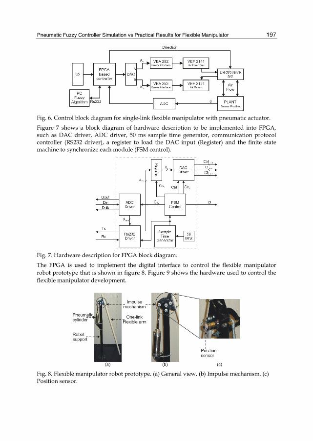
3.3 Experimental description Figure 6 shows a functionally block diagram of the system. The ADC is a 12-bit ADS7841 device, with a synchronous serial interface communication, 4-channel and up to 200 KHz conversion rate. The DAC is a 12-bit DAC7624 device, with quad voltage output, parallel input data and 10 µs of settling time. Both DAC and ADC are manufactured by Texas Instruments. The DAC is used to control the proportional valve, and the ADC is used to read the flexible arm position with a 10KΩ resistive sensor, which output value has an interval of 0 to 2 V. Finally, an FPGA is used to implement the digital interfaces with the personal computer, and the PD FPGA based controller.
Pneumatic Fuzzy Controller Simulation vs Practical Results for Flexible Manipulator
197
Fig. 6. Control block diagram for single-link flexible manipulator with pneumatic actuator.
Figure 7 shows a block diagram of hardware description to be implemented into FPGA, such as DAC driver, ADC driver, 50 ms sample time generator, communication protocol controller (RS232 driver), a register to load the DAC input (Register) and the finite state machine to synchronize each module (FSM control).
Fig. 7. Hardware description for FPGA block diagram.
The FPGA is used to implement the digital interface to control the flexible manipulator robot prototype that is shown in figure 8. Figure 9 shows the hardware used to control the flexible manipulator development.
Fig. 8. Flexible manipulator robot prototype. (a) General view. (b) Impulse mechanism. (c) Position sensor.
Automation and Robotics
198
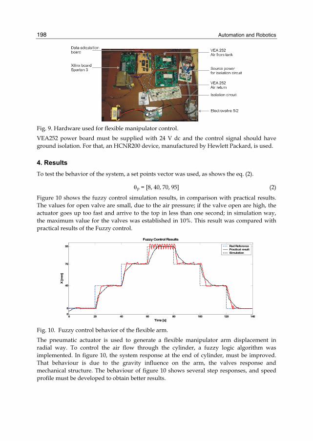
Fig. 9. Hardware used for flexible manipulator control.
VEA252 power board must be supplied with 24 V dc and the control signal should have ground isolation. For that, an HCNR200 device, manufactured by Hewlett Packard, is used.
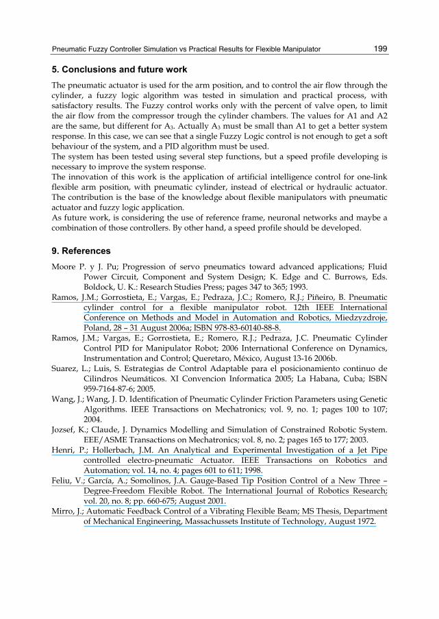
4. Results To test the behavior of the system, a set points vector was used, as shows the eq. (2).
θp = [8, 40, 70, 95] (2)
Figure 10 shows the fuzzy control simulation results, in comparison with practical results. The values for open valve are small, due to the air pressure; if the valve open are high, the actuator goes up too fast and arrive to the top in less than one second; in simulation way, the maximum value for the valves was established in 10%. This result was compared with practical results of the Fuzzy control.
0 20 40 60 80 100 120 1400
8
40
70
95
Fuzzy Control Results
X [m
m]
Time [s]
Rod ReferencePractical resultSimulation
Fig. 10. Fuzzy control behavior of the flexible arm.
The pneumatic actuator is used to generate a flexible manipulator arm displacement in radial way. To control the air flow through the cylinder, a fuzzy logic algorithm was implemented. In figure 10, the system response at the end of cylinder, must be improved. That behaviour is due to the gravity influence on the arm, the valves response and mechanical structure. The behaviour of figure 10 shows several step responses, and speed profile must be developed to obtain better results.
Pneumatic Fuzzy Controller Simulation vs Practical Results for Flexible Manipulator
199
5. Conclusions and future work The pneumatic actuator is used for the arm position, and to control the air flow through the cylinder, a fuzzy logic algorithm was tested in simulation and practical process, with satisfactory results. The Fuzzy control works only with the percent of valve open, to limit the air flow from the compressor trough the cylinder chambers. The values for A1 and A2 are the same, but different for A3. Actually A3 must be small than A1 to get a better system response. In this case, we can see that a single Fuzzy Logic control is not enough to get a soft behaviour of the system, and a PID algorithm must be used. The system has been tested using several step functions, but a speed profile developing is necessary to improve the system response. The innovation of this work is the application of artificial intelligence control for one-link flexible arm position, with pneumatic cylinder, instead of electrical or hydraulic actuator. The contribution is the base of the knowledge about flexible manipulators with pneumatic actuator and fuzzy logic application. As future work, is considering the use of reference frame, neuronal networks and maybe a combination of those controllers. By other hand, a speed profile should be developed.
9. References Moore P. y J. Pu; Progression of servo pneumatics toward advanced applications; Fluid
Power Circuit, Component and System Design; K. Edge and C. Burrows, Eds. Boldock, U. K.: Research Studies Press; pages 347 to 365; 1993.
Ramos, J.M.; Gorrostieta, E.; Vargas, E.; Pedraza, J.C.; Romero, R.J.; Piñeiro, B. Pneumatic cylinder control for a flexible manipulator robot. 12th IEEE International Conference on Methods and Model in Automation and Robotics, Miedzyzdroje, Poland, 28 – 31 August 2006a; ISBN 978-83-60140-88-8.
Ramos, J.M.; Vargas, E.; Gorrostieta, E.; Romero, R.J.; Pedraza, J.C. Pneumatic Cylinder Control PID for Manipulator Robot; 2006 International Conference on Dynamics, Instrumentation and Control; Queretaro, México, August 13-16 2006b.
Suarez, L.; Luis, S. Estrategias de Control Adaptable para el posicionamiento continuo de Cilindros Neumáticos. XI Convencion Informatica 2005; La Habana, Cuba; ISBN 959-7164-87-6; 2005.
Wang, J.; Wang, J. D. Identification of Pneumatic Cylinder Friction Parameters using Genetic Algorithms. IEEE Transactions on Mechatronics; vol. 9, no. 1; pages 100 to 107; 2004.
Jozsef, K.; Claude, J. Dynamics Modelling and Simulation of Constrained Robotic System. EEE/ASME Transactions on Mechatronics; vol. 8, no. 2; pages 165 to 177; 2003.
Henri, P.; Hollerbach, J.M. An Analytical and Experimental Investigation of a Jet Pipe controlled electro-pneumatic Actuator. IEEE Transactions on Robotics and Automation; vol. 14, no. 4; pages 601 to 611; 1998.
Feliu, V.; García, A.; Somolinos, J.A. Gauge-Based Tip Position Control of a New Three –Degree-Freedom Flexible Robot. The International Journal of Robotics Research; vol. 20, no. 8; pp. 660-675; August 2001.
Mirro, J.; Automatic Feedback Control of a Vibrating Flexible Beam; MS Thesis, Department of Mechanical Engineering, Massachussets Institute of Technology, August 1972.
Automation and Robotics
200
Whitney, D.E.; Book, W.J.; Lynch, P.M. Design and Control Considerations for Industrial and Space Manipulators; Proceedings of the Joint Automatic Control Conference, June, 1974.
Burrows, C.R.; Webb C.R. Simulation of an On – Off Pneumatic Servomechanism; Automatic Control Group, 1968.
Quiles, E.; Morant, F.; García, E.; Blasco, R.; Correcher, A. Control Adaptivo de un Sistema de Control Neumatico. 3ra. Conferencia Iberoamericana en Sistemas, Cibernetica e Informatica CISCI, Julio 2004.
Burbano, J.C.; Bacca, G.; Hoyos, M. Control de Posicion y Presion para Manipulador Neumatico a traves de PC. Scientia Et Tecnica, UTP; vol. 21, pp. 71-76; 2003.
Pérez, J. Analisis Dinamico de Mecanismos Accionados Neumaticamente. Ph.D. Thesis; Facultad de Ingeniería Mecanica, Electrica y Electronica, FIMEE; Salamanca, Gto.; March 2003.
Kiyama, F.; Vargas, J. Modelo Termo-Mecanico para un Manipulador tipo Dielectrico. Informacion Tecnologica; vol. 15; no 5; pages 23 to 31; 2004; ISSN 0716-8756.
Feliu, V.; Garcia, A. Gauge-Based tip Position Control of a New Three Degree of Freedom Flexible Robot. The International Journal of Robotics Research; vol. 20, no. 8; pp. 660-675; 2001.
Ramos, J.M.; Vargas, J.E.; Gorrostieta, E.; Pedraza, J.C. Nuevo Modelo Polinomial del Comportamiento de un Cilindro Neumatico. Revista Internacional Informacion Tecnologica; vol. 17, no. 3; ISSN 0716-8756; 2006.
Related Documents