Journal of Mechanical Science and Technology 21 (2007) 1018~1027 Journal of Mechanical Science and Technology Control of Two-Axis Pneumatic Artificial Muscle Manipulator with a New Phase Plane Switching Control Method TU Diep Cong Thanh b , Kyoung Kwan AHN a,* a School of Mechanical and Automotive Engineering, University of Ulsan, Korea b Mechatronics Department, Ho Chi Minh City University of Technology, Viet Nam (Manuscript Received September 25, 2006; Revised April 24, 2007; Accepted April 24 2007) -------------------------------------------------------------------------------------------------------------------------------------------------------------------------------------------------------------------------------------------------------- Abstract The use of robots in rehabilitation has become an issue of increasing importance because of the requirement of functional recovery therapy for limbs. A novel pneumatic artificial muscle (PAM) actuator – which has achieved increased popularity for providing safety and mobility assistance to humans performing tasks, as well as providing another advantages such as high strength and power/weight ratio, low cost, compactness, ease of maintenance, cleanliness, readily available, cheap power source, and so on – has been considered during the recent decades for use in a therapy robot, which in particular requires a high level of safety. However, some limitations still exist, such as air compressibility and the lack of damping ability of the actuator to bring the dynamic delay of the pressure response and cause the oscillatory motion. In addition, to aid rehabilitation more efficiently, the robot should adjust its impedance parameters according to the physical condition of the patient. For this purpose, the manipulator join is equipped with a Magneto-Rheological Brake (MRB). A new phase plane switching control method using MRB is proposed for tracking sinusoidal waveforms. The effectiveness of the proposed algorithm is demonstrated through an experiment using a fabricated two-axis PAM manipulator. The experiment proves that the stability of the manipulator could be greatly improved using a high gain control without regard to the change of the frequencies of the reference input and the external load condition, and without decreasing the response speed or lowering the stiffness of PAM manipulator. Keywords: Pneumatic artificial muscle; Phase plane switching control; Manipulator; Magneto-rheological brake -------------------------------------------------------------------------------------------------------------------------------------------------------------------------------------------------------------------------------------------------------- 1. Introduction The number of people requiring rehabilitation due to bone fracture or joint disease caused by traffic accidents and cerebral apoplexy, and for functional motor problems due to advanced age, numbers several hundreds of thousands worldwide. The application of robotics to rehabilitation is thus of great concern. Functional recovery therapy is normally carried out by medical therapists on a person-to- person basis, but automatic equipment has been put to practical use in physical therapy programs that repeat relatively simple operations, such as a continuous passive motion machine, a walking training device, and a torque machine used for a single axis (Doi, 1993; Fujie et al., 1994; Fujie et al., 1995). This research deals with functional recovery therapy, one important aspect of physical rehabilitation. Single- joint therapy machines have already been created (Ahn and Thanh, 2004; 2005a; 2005b). However, multi-joint robots are necessary to achieve more realistic motion patterns, and hence are necessary for more efficient therapy. This kind of robot must have a high level of safety for human use. The PAM mani- pulator has been used to construct a therapy robot with two degrees of freedom (DOF). A 2-DOF robot for functional recovery therapy driven by pneumatic * Corresponding author. Tel.: +82 52 259 2282, Fax.: +82 52 259 1680 E-mail address: [email protected]

Welcome message from author
This document is posted to help you gain knowledge. Please leave a comment to let me know what you think about it! Share it to your friends and learn new things together.
Transcript
Journal of Mechanical Science and Technology 21 (2007) 1018~1027
Journal of
MechanicalScience andTechnology
Control of Two-Axis Pneumatic Artificial Muscle Manipulator with a
New Phase Plane Switching Control Method
TU Diep Cong Thanhb, Kyoung Kwan AHNa,* a School of Mechanical and Automotive Engineering, University of Ulsan, Korea
b Mechatronics Department, Ho Chi Minh City University of Technology, Viet Nam
(Manuscript Received September 25, 2006; Revised April 24, 2007; Accepted April 24 2007)
--------------------------------------------------------------------------------------------------------------------------------------------------------------------------------------------------------------------------------------------------------
Abstract
The use of robots in rehabilitation has become an issue of increasing importance because of the requirement of
functional recovery therapy for limbs. A novel pneumatic artificial muscle (PAM) actuator – which has achieved
increased popularity for providing safety and mobility assistance to humans performing tasks, as well as providing
another advantages such as high strength and power/weight ratio, low cost, compactness, ease of maintenance,
cleanliness, readily available, cheap power source, and so on – has been considered during the recent decades for use in
a therapy robot, which in particular requires a high level of safety. However, some limitations still exist, such as air
compressibility and the lack of damping ability of the actuator to bring the dynamic delay of the pressure response and
cause the oscillatory motion. In addition, to aid rehabilitation more efficiently, the robot should adjust its impedance
parameters according to the physical condition of the patient. For this purpose, the manipulator join is equipped with a
Magneto-Rheological Brake (MRB). A new phase plane switching control method using MRB is proposed for tracking
sinusoidal waveforms. The effectiveness of the proposed algorithm is demonstrated through an experiment using a
fabricated two-axis PAM manipulator. The experiment proves that the stability of the manipulator could be greatly
improved using a high gain control without regard to the change of the frequencies of the reference input and the
external load condition, and without decreasing the response speed or lowering the stiffness of PAM manipulator.
Keywords: Pneumatic artificial muscle; Phase plane switching control; Manipulator; Magneto-rheological brake
--------------------------------------------------------------------------------------------------------------------------------------------------------------------------------------------------------------------------------------------------------
1. Introduction
The number of people requiring rehabilitation due
to bone fracture or joint disease caused by traffic
accidents and cerebral apoplexy, and for functional
motor problems due to advanced age, numbers
several hundreds of thousands worldwide. The
application of robotics to rehabilitation is thus of great
concern. Functional recovery therapy is normally
carried out by medical therapists on a person-to-
person basis, but automatic equipment has been put to
practical use in physical therapy programs that repeat
relatively simple operations, such as a continuous
passive motion machine, a walking training device,
and a torque machine used for a single axis (Doi,
1993; Fujie et al., 1994; Fujie et al., 1995). This
research deals with functional recovery therapy, one
important aspect of physical rehabilitation. Single-
joint therapy machines have already been created
(Ahn and Thanh, 2004; 2005a; 2005b). However,
multi-joint robots are necessary to achieve more
realistic motion patterns, and hence are necessary for
more efficient therapy. This kind of robot must have a
high level of safety for human use. The PAM mani-
pulator has been used to construct a therapy robot
with two degrees of freedom (DOF). A 2-DOF robot
for functional recovery therapy driven by pneumatic
*Corresponding author. Tel.: +82 52 259 2282, Fax.: +82 52 259 1680
E-mail address: [email protected]
TU Diep Cong Thanh and Kyoung Kwan AHN / Journal of Mechanical Science and Technology 21(2007) 1018~1027 1019
muscle was developed by Zobel (Zobel et al., 1999)
and Raparelli (Raparelli et al., 2001; 2003) artificial
muscle actuators for biorobotic systems by Klute
(Klute et al., 1999; 2000; 2002; 2003) a pneumatic
muscle hand therapy device by Koeneman (Koene-
man et al., 2004) and a human-friendly therapy robot
(Thanh and Ahn, 2006a). However, some limitations
still exist, such as the air compressibility and the lack
of damping ability of the actuator to bring the
dynamic delay of the pressure response, causing
oscillatory motion. In addition, to execute reha-
bilitation more efficiently, the robot must adjust its
impedance parameters according to the physical
condition of the patient. For this purpose, a new
technology, an electro-rheological fluid damper (ER
Damper), has been applied to the PAM manipulator.
Noritsugu and his team used an ER damper to
improve the control performance of the PAM
manipulator with a PI controller and pulse code-
modulated on-off valves (Noritsugu et al., 1994). By
separating the region where the damper produces a
damping torque to reconcile both damping and
response speed under high gain control, the results
show that the ER damper is an effective method for
use in a practically available, human-friendly robot
using the PAM manipulator. Moreover, position
control is improved without a decrease in response
speed. However, some limitations hamper the
technology, since ER Fluid (ERF) requires extremely
high control voltage (kV), which is problematic, and
in particular, potentially dangerous, only operates in a
narrow temperature range (and one unsuitable for
PAM manipulators), and exhibits nonlinear charac-
teristics. Because ERF has many unacceptable dis-
advantages, magneto-rheological fluid (MRF) has
been considered an attractive alternative for the
advantages listed in Table 1, and has been recently
used in human-friendly therapy robots (Thanh and
Ahn, 2006b). Though these systems were successful
in addressing smooth actuator motion response to step
inputs, assuming that two axes PAM manipulator is
utilized in therapy robot in the future, which is the
final goal of our research, it is necessary to realize fast
response, even if the external inertia load changes
severely with sinusoidal response without regard to
the various frequencies.
Therefore, to realize satisfactory control perfor-
mance, a MRB is equipped to the joint of the mani-
pulator. A phase plane switching control method using
a MRB is proposed for the case of tracking sinusoidal
waveforms, and the effectiveness of the proposed
algorithm will be demonstrated through the experi-
ments involving a two-axis PAM manipulator. The
experiments show that the stability of the manipulator
could be greatly improved under a high gain control
without regard to variations of the frequencies re-
ference and external load conditions, and without
decreasing the response speed and low stiffness of the
two-axis PAM manipulator.
2. Experimental setup
2.1 Experimental apparatus
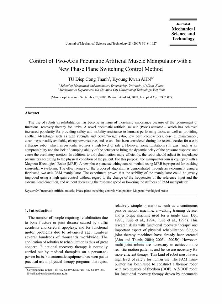
The schematic diagram of the two-axis pneumatic
artificial muscle manipulator is shown in Fig. 1. The
Table 1. Comparison of rheological fluids.
Magneto-Rheological
Fluid Electro-Rheological
Fluid
Max. Yield Stress 50 –100 kPa 2 – 5 kPa
Viscosity 0.1 – 1.0 Pa-s 0.1 – 1.0 Pa-s
Operable Temp. Range
-40 to + 150 oC
+10 to + 90 oC (ionic,
DC) -25 to + 125
oC (non-
ionic, AC)
Stability Unaffected by most
impurities Cannot tolerate
impurities
Response Time < milliseconds < milliseconds
Density 3 – 4 g/cm3 1 – 2 g/cm
3
Max. Energy Density
0.1 Joule/cm3 0.001 Joule/cm
3
Power Supply2 – 25 V @ 1 – 2 A
(2 – 50 watts) 2 – 25 KV @ 1 – 10 mA
(2 – 50 watts)
Fig. 1. Schematic diagram of two axes pneumatic artificial
muscle manipulator.
1020 TU Diep Cong Thanh and Kyoung Kwan AHN / Journal of Mechanical Science and Technology 21(2007) 1018~1027
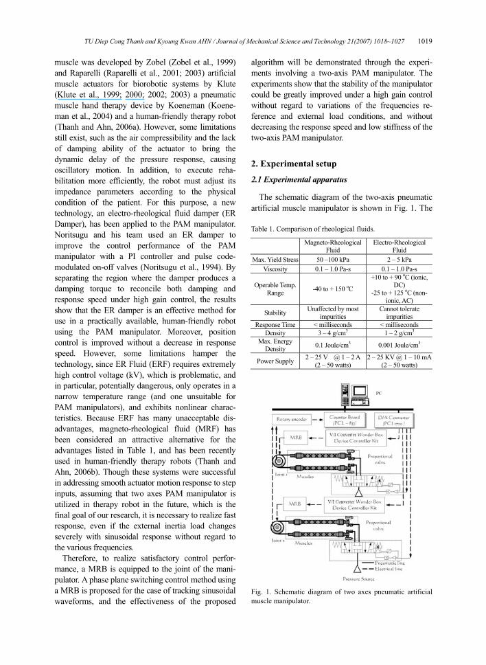
Fig. 2. Working principle of the pneumatic artificial muscle
manipulator.
Fig. 3. Photograph of the experimental apparatus.
Fig. 4. Construction of MRB.
the pressure difference between the antagonistic
artificial muscles and the external load is rotated as a
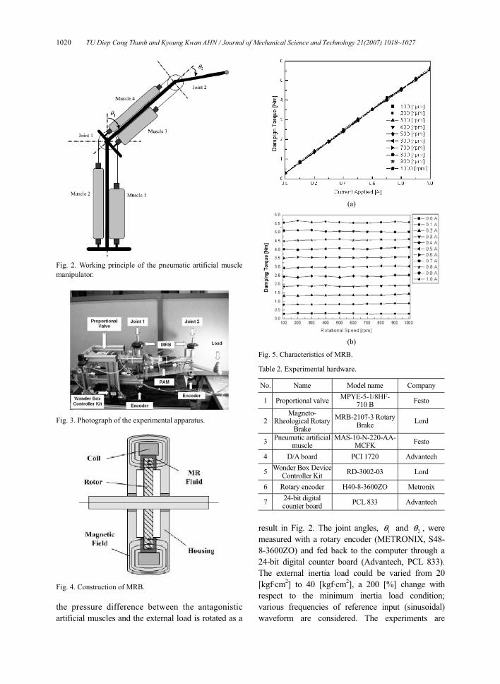
(a)
(b)
Fig. 5. Characteristics of MRB.
Table 2. Experimental hardware.
No. Name Model name Company
1 Proportional valveMPYE-5-1/8HF-
710 B Festo
2Magneto-
Rheological Rotary Brake
MRB-2107-3 Rotary Brake
Lord
3Pneumatic artificial
muscle MAS-10-N-220-AA-
MCFK Festo
4 D/A board PCI 1720 Advantech
5Wonder Box Device
Controller Kit RD-3002-03 Lord
6 Rotary encoder H40-8-3600ZO Metronix
724-bit digital counter board
PCL 833 Advantech
result in Fig. 2. The joint angles, 1θ and 2θ , were
measured with a rotary encoder (METRONIX, S48-
8-3600ZO) and fed back to the computer through a
24-bit digital counter board (Advantech, PCL 833).
The external inertia load could be varied from 20
[kgf·cm2] to 40 [kgf·cm
2], a 200 [%] change with
respect to the minimum inertia load condition;
various frequencies of reference input (sinusoidal)
waveform are considered. The experiments are
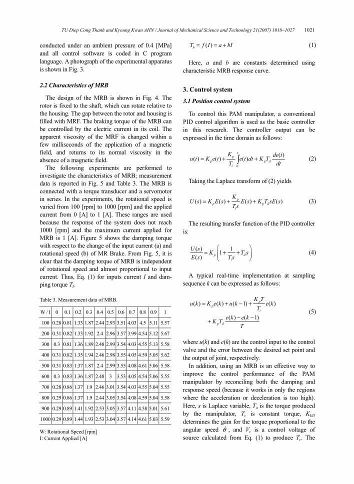
TU Diep Cong Thanh and Kyoung Kwan AHN / Journal of Mechanical Science and Technology 21(2007) 1018~1027 1021
conducted under an ambient pressure of 0.4 [MPa]
and all control software is coded in C program
language. A photograph of the experimental apparatus
is shown in Fig. 3.
2.2 Characteristics of MRB
The design of the MRB is shown in Fig. 4. The
rotor is fixed to the shaft, which can rotate relative to
the housing. The gap between the rotor and housing is
filled with MRF. The braking torque of the MRB can
be controlled by the electric current in its coil. The
apparent viscosity of the MRF is changed within a
few milliseconds of the application of a magnetic
field, and returns to its normal viscosity in the
absence of a magnetic field.
The following experiments are performed to
investigate the characteristics of MRB; measurement
data is reported in Fig. 5 and Table 3. The MRB is
connected with a torque transducer and a servomotor
in series. In the experiments, the rotational speed is
varied from 100 [rpm] to 1000 [rpm] and the applied
current from 0 [A] to 1 [A]. These ranges are used
because the response of the system does not reach
1000 [rpm] and the maximum current applied for
MRB is 1 [A]. Figure 5 shows the damping torque
with respect to the change of the input current (a) and
rotational speed (b) of MR Brake. From Fig. 5, it is
clear that the damping torque of MRB is independent
of rotational speed and almost proportional to input
current. Thus, Eq. (1) for inputs current I and dam-
ping torque Tb
Table 3. Measurement data of MRB.
W / I 0 0.1 0.2 0.3 0.4 0.5 0.6 0.7 0.8 0.9 1
100 0.28 0.81 1.33 1.87 2.44 2.93 3.51 4.03 4.5 5.11 5.57
200 0.31 0.82 1.33 1.92 2.4 2.96 3.57 3.99 4.54 5.12 5.67
300 0.3 0.81 1.36 1.89 2.48 2.99 3.54 4.03 4.55 5.13 5.58
400 0.31 0.82 1.35 1.94 2.46 2.98 3.55 4.05 4.59 5.05 5.62
500 0.31 0.83 1.37 1.87 2.4 2.99 3.55 4.08 4.61 5.06 5.58
600 0.3 0.83 1.36 1.87 2.48 3 3.53 4.05 4.54 5.06 5.55
700 0.28 0.86 1.37 1.9 2.46 3.01 3.54 4.03 4.55 5.04 5.55
800 0.29 0.86 1.37 1.9 2.44 3.05 3.54 4.08 4.59 5.04 5.58
900 0.29 0.89 1.41 1.92 2.53 3.05 3.57 4.11 4.58 5.01 5.61
1000 0.29 0.89 1.44 1.93 2.53 3.04 3.57 4.14 4.61 5.03 5.59
W: Rotational Speed [rpm]
I: Current Applied [A]
( )bT f I a bI= = + (1)
Here, a and b are constants determined using
characteristic MRB response curve.
3. Control system
3.1 Position control system
To control this PAM manipulator, a conventional
PID control algorithm is used as the basic controller
in this research. The controller output can be
expressed in the time domain as follows:
0
( )( ) ( ) ( )
tp
p p di
K de tu t K e t e t dt K TT dt
= + +� (2)
Taking the Laplace transform of (2) yields
( ) ( ) ( ) ( )p
p p di
KU s K E s E s K T sE s
T s= + + (3)
The resulting transfer function of the PID controller
is:
( ) 11
( )p d
i
U s K T sE s T s
� �= + +� �� �
� � (4)
A typical real-time implementation at sampling
sequence k can be expressed as follows:
( ) ( ) ( 1) ( )
( ) ( 1)
pp
i
p d
K Tu k K e k u k e k
Te k e kK T
T
= + − +
− −+ (5)
where u(k) and e(k) are the control input to the control
valve and the error between the desired set point and
the output of joint, respectively.
In addition, using an MRB is an effective way to
improve the control performance of the PAM
manipulator by reconciling both the damping and
response speed (because it works in only the regions
where the acceleration or deceleration is too high).
Here, s is Laplace variable, Ta is the torque produced
by the manipulator, Tc is constant torque, KED
determines the gain for the torque proportional to the
angular speed θ� , and Vc is a control voltage of
source calculated from Eq. (1) to produce Tc. The
1022 TU Diep Cong Thanh and Kyoung Kwan AHN / Journal of Mechanical Science and Technology 21(2007) 1018~1027
direction of the damping torque is opposite to the
direction of rotation of the arm. Therefore, Eq. (6)
below indicates that the damper produces a damping
torque Tb.
( ) ( )b ED cT K T signθ θ= +� � (6)
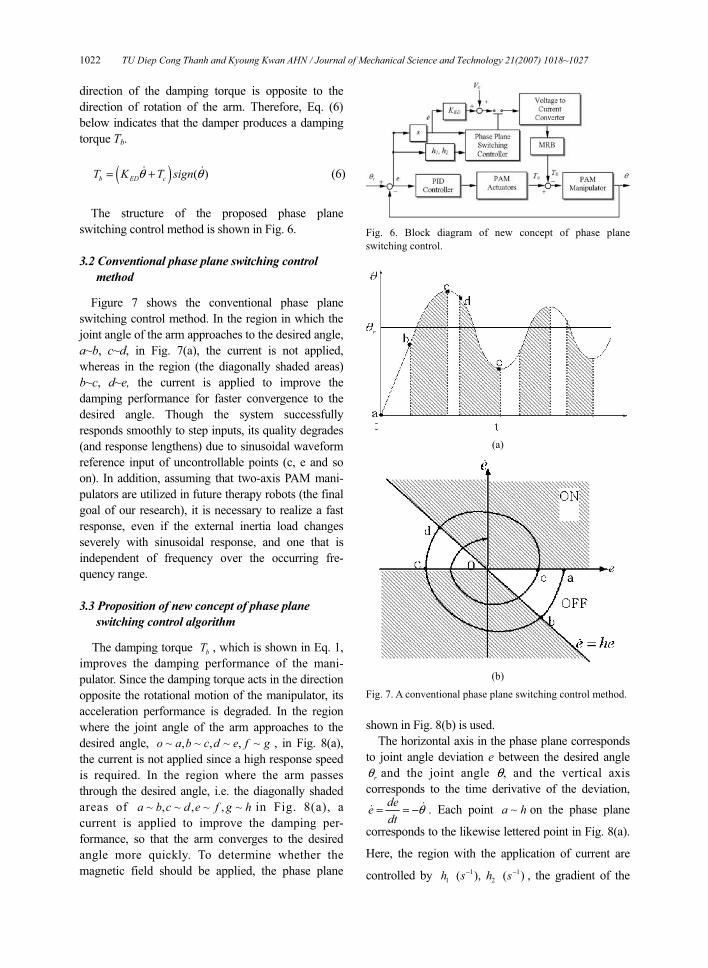
The structure of the proposed phase plane
switching control method is shown in Fig. 6.
3.2 Conventional phase plane switching control method
Figure 7 shows the conventional phase plane
switching control method. In the region in which the
joint angle of the arm approaches to the desired angle,
a~b, c~d, in Fig. 7(a), the current is not applied,
whereas in the region (the diagonally shaded areas)
b~c, d~e, the current is applied to improve the
damping performance for faster convergence to the
desired angle. Though the system successfully
responds smoothly to step inputs, its quality degrades
(and response lengthens) due to sinusoidal waveform
reference input of uncontrollable points (c, e and so
on). In addition, assuming that two-axis PAM mani-
pulators are utilized in future therapy robots (the final
goal of our research), it is necessary to realize a fast
response, even if the external inertia load changes
severely with sinusoidal response, and one that is
independent of frequency over the occurring fre-
quency range.
3.3 Proposition of new concept of phase plane switching control algorithm
The damping torque bT , which is shown in Eq. 1,
improves the damping performance of the mani-
pulator. Since the damping torque acts in the direction
opposite the rotational motion of the manipulator, its
acceleration performance is degraded. In the region
where the joint angle of the arm approaches to the
desired angle, ~ , ~ , ~ , ~o a b c d e f g , in Fig. 8(a),
the current is not applied since a high response speed
is required. In the region where the arm passes
through the desired angle, i.e. the diagonally shaded
areas of ~ , ~ , ~ , ~a b c d e f g h in Fig. 8(a), a
current is applied to improve the damping per-
formance, so that the arm converges to the desired
angle more quickly. To determine whether the
magnetic field should be applied, the phase plane
Fig. 6. Block diagram of new concept of phase plane
switching control.
(a)
(b)
Fig. 7. A conventional phase plane switching control method.
shown in Fig. 8(b) is used.
The horizontal axis in the phase plane corresponds
to joint angle deviation e between the desired angle
rθ and the joint angle θ, and the vertical axis
corresponds to the time derivative of the deviation, deedt
θ= = − �� . Each point ~a h on the phase plane
corresponds to the likewise lettered point in Fig. 8(a).
Here, the region with the application of current are
controlled by 1 1
1 2( ), ( )h s h s− − , the gradient of the
TU Diep Cong Thanh and Kyoung Kwan AHN / Journal of Mechanical Science and Technology 21(2007) 1018~1027 1023
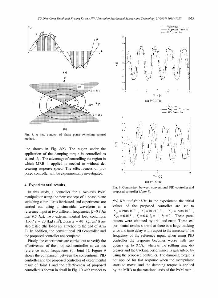
(a)
(b)
Fig. 8. A new concept of phase plane switching control
method.
line shown in Fig. 8(b). The region under the
application of the damping torque is controlled as
1h and 2h . The advantage of controlling the region in
which MRB is applied is needed to without de-
creasing response speed. The effectiveness of pro-
posed controller will be experimentally investigated.
4. Experimental results
In this study, a controller for a two-axis PAM
manipulator using the new concept of a phase plane
switching controller is fabricated, and experiments are
carried out using a sinusoidal waveform as a
reference input at two different frequencies (f=0.3 Hz and 0.5 Hz). Two external inertial load conditions
(Load 1 = 20 [kgf·cm2]; Load 2 = 40 [kgf·cm
2]) are
also tested (the loads are attached to the end of Arm
2). In addition, the conventional PID controller and
the proposed controller are compared.
Firstly, the experiments are carried out to verify the
effectiveness of the proposed controller at various
reference input frequencies (of Joint 1). Figure 9
shows the comparison between the conventional PID
controller and the proposed controller of experimental
result of Joint 1 and the effectiveness of proposed
controlled is shown in detail in Fig. 10 with respect to
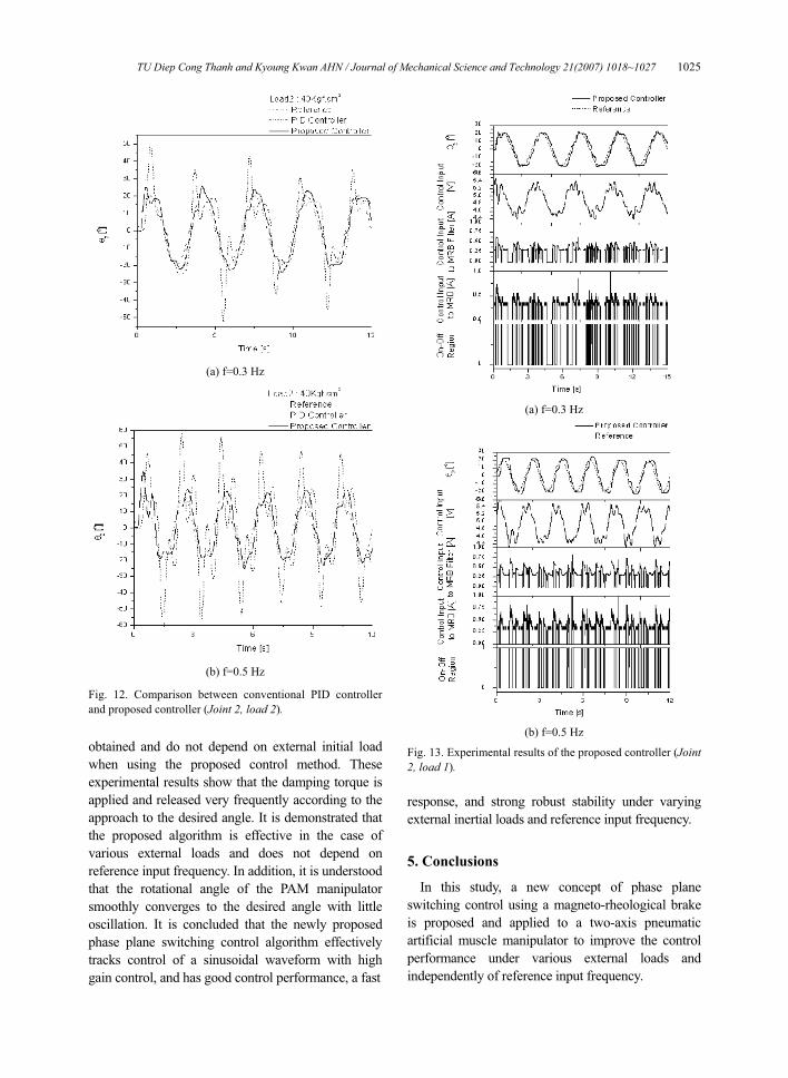
(a) f=0.3 Hz
(b) f=0.5 Hz
Fig. 9. Comparison between conventional PID controller and
proposed controller (Joint 1). f=0.3Hz and f=0.5Hz. In the experiment, the initial
values of the proposed controller are set to 6190 10pK −= × , 610 10iK −= × , 6150 10dK −= × ,
0.015EDK = , 1 20.8, 1, 2cT h h= = − = . These para-
meters were obtained by trial-and-error. These ex-
perimental results show that there is a large tracking
error and time delay with respect to the increase of the
frequency of the reference input; when using PID
controller the response becomes worse with fre-
quency up to 0.5Hz, whereas the settling time de-
creases and the tracking performance is guaranteed by
using the proposed controller. The damping torque is
not applied for fast response when the manipulator
starts to move, and the damping torque is applied
by the MRB to the rotational axis of the PAM mani-
1024 TU Diep Cong Thanh and Kyoung Kwan AHN / Journal of Mechanical Science and Technology 21(2007) 1018~1027
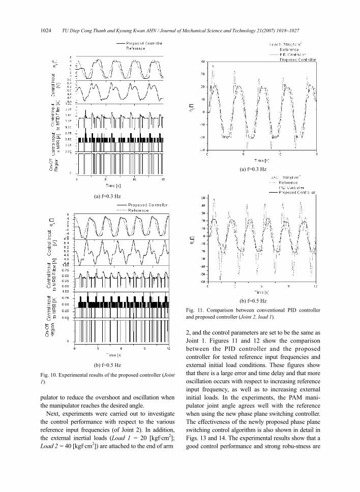
(a) f=0.3 Hz
(b) f=0.5 Hz
Fig. 10. Experimental results of the proposed controller (Joint 1).
pulator to reduce the overshoot and oscillation when
the manipulator reaches the desired angle.
Next, experiments were carried out to investigate
the control performance with respect to the various
reference input frequencies (of Joint 2). In addition,
the external inertial loads (Load 1 = 20 [kgf·cm2];
Load 2 = 40 [kgf·cm2]) are attached to the end of arm
(a) f=0.3 Hz
(b) f=0.5 Hz
Fig. 11. Comparison between conventional PID controller
and proposed controller (Joint 2, load 1).
2, and the control parameters are set to be the same as
Joint 1. Figures 11 and 12 show the comparison
between the PID controller and the proposed
controller for tested reference input frequencies and
external initial load conditions. These figures show
that there is a large error and time delay and that more
oscillation occurs with respect to increasing reference
input frequency, as well as to increasing external
initial loads. In the experiments, the PAM mani-
pulator joint angle agrees well with the reference
when using the new phase plane switching controller.
The effectiveness of the newly proposed phase plane
switching control algorithm is also shown in detail in
Figs. 13 and 14. The experimental results show that a
good control performance and strong robu-stness are
TU Diep Cong Thanh and Kyoung Kwan AHN / Journal of Mechanical Science and Technology 21(2007) 1018~1027 1025
(a) f=0.3 Hz
(b) f=0.5 Hz
Fig. 12. Comparison between conventional PID controller
and proposed controller (Joint 2, load 2).
obtained and do not depend on external initial load
when using the proposed control method. These
experimental results show that the damping torque is
applied and released very frequently according to the
approach to the desired angle. It is demonstrated that
the proposed algorithm is effective in the case of
various external loads and does not depend on
reference input frequency. In addition, it is understood
that the rotational angle of the PAM manipulator
smoothly converges to the desired angle with little
oscillation. It is concluded that the newly proposed
phase plane switching control algorithm effectively
tracks control of a sinusoidal waveform with high
gain control, and has good control performance, a fast
(a) f=0.3 Hz
(b) f=0.5 Hz
Fig. 13. Experimental results of the proposed controller (Joint 2, load 1).
response, and strong robust stability under varying
external inertial loads and reference input frequency.
5. Conclusions
In this study, a new concept of phase plane
switching control using a magneto-rheological brake
is proposed and applied to a two-axis pneumatic
artificial muscle manipulator to improve the control
performance under various external loads and
independently of reference input frequency.
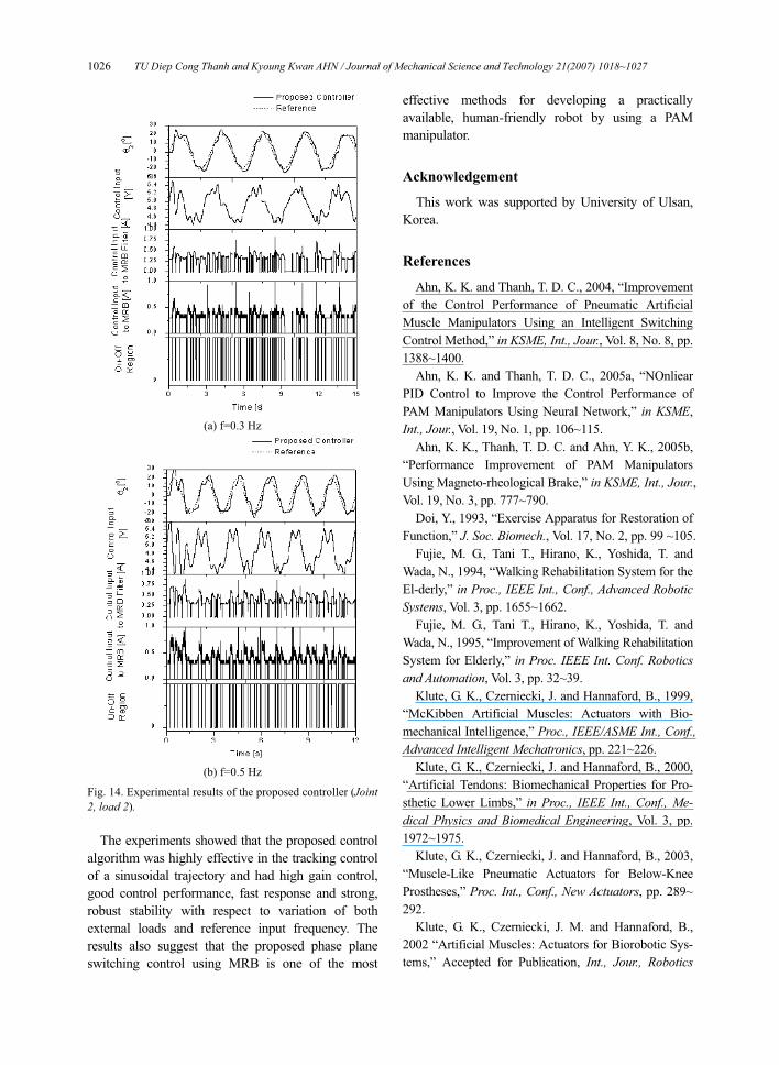
1026 TU Diep Cong Thanh and Kyoung Kwan AHN / Journal of Mechanical Science and Technology 21(2007) 1018~1027
(a) f=0.3 Hz
(b) f=0.5 Hz
Fig. 14. Experimental results of the proposed controller (Joint 2, load 2).
The experiments showed that the proposed control
algorithm was highly effective in the tracking control
of a sinusoidal trajectory and had high gain control,
good control performance, fast response and strong,
robust stability with respect to variation of both
external loads and reference input frequency. The
results also suggest that the proposed phase plane
switching control using MRB is one of the most
effective methods for developing a practically
available, human-friendly robot by using a PAM
manipulator.
Acknowledgement
This work was supported by University of Ulsan,
Korea.
References
Ahn, K. K. and Thanh, T. D. C., 2004, “Improvement
of the Control Performance of Pneumatic Artificial
Muscle Manipulators Using an Intelligent Switching
Control Method,” in KSME, Int., Jour., Vol. 8, No. 8, pp.
1388~1400.
Ahn, K. K. and Thanh, T. D. C., 2005a, “NOnliear
PID Control to Improve the Control Performance of
PAM Manipulators Using Neural Network,” in KSME,
Int., Jour., Vol. 19, No. 1, pp. 106~115.
Ahn, K. K., Thanh, T. D. C. and Ahn, Y. K., 2005b,
“Performance Improvement of PAM Manipulators
Using Magneto-rheological Brake,” in KSME, Int., Jour., Vol. 19, No. 3, pp. 777~790.
Doi, Y., 1993, “Exercise Apparatus for Restoration of
Function,” J. Soc. Biomech., Vol. 17, No. 2, pp. 99 ~105.
Fujie, M. G., Tani T., Hirano, K., Yoshida, T. and
Wada, N., 1994, “Walking Rehabilitation System for the
El-derly,” in Proc., IEEE Int., Conf., Advanced Robotic Systems, Vol. 3, pp. 1655~1662.
Fujie, M. G., Tani T., Hirano, K., Yoshida, T. and
Wada, N., 1995, “Improvement of Walking Rehabilitation
System for Elderly,” in Proc. IEEE Int. Conf. Robotics and Automation, Vol. 3, pp. 32~39.
Klute, G. K., Czerniecki, J. and Hannaford, B., 1999,
“McKibben Artificial Muscles: Actuators with Bio-
mechanical Intelligence,” Proc., IEEE/ASME Int., Conf., Advanced Intelligent Mechatronics, pp. 221~226.
Klute, G. K., Czerniecki, J. and Hannaford, B., 2000,
“Artificial Tendons: Biomechanical Properties for Pro-
sthetic Lower Limbs,” in Proc., IEEE Int., Conf., Me-dical Physics and Biomedical Engineering, Vol. 3, pp.
1972~1975.
Klute, G. K., Czerniecki, J. and Hannaford, B., 2003,
“Muscle-Like Pneumatic Actuators for Below-Knee
Prostheses,” Proc. Int., Conf., New Actuators, pp. 289~
292.
Klute, G. K., Czerniecki, J. M. and Hannaford, B.,
2002 “Artificial Muscles: Actuators for Biorobotic Sys-
tems,” Accepted for Publication, Int., Jour., Robotics
TU Diep Cong Thanh and Kyoung Kwan AHN / Journal of Mechanical Science and Technology 21(2007) 1018~1027 1027
Research Koeneman, E. J., Schultz, R. S., Wolf, S. L., Herring,
D. E. and Koeneman, J. B., 2004, “A Pneumatic Muscle
Hand Therapy Device,” in Proc., IEEE/EMBS Int., Conf., pp. 2711~2713.
Noritsugu, T, Tsuji, Y. and Ito, K., 1994, “Improve-
ment of Control Performance of Pneumatic Rubber
Artificial Muscle Manipulator by Using Electro-
rheological Fluid Damper,” in Proc., IEEE, Int., Conf., Syst Man Cybernet, Vol. 4, pp. 788~793.
Raparelli, T., Zobel, P. B. and Durante, F., 2001, “The
Design of a 2 DOF Robot for Functional Recovery
Therapy Driven by Pneumatic Muscles,” Int., Workshop on robotics in ALPA – DRIA -DANUBE region
Raparelli, T., Zobel, P. B. and Durante, F., 2003,
“Development of a Robot Driven by Pneumatic Muscles,”
Proc., RAAD, Workshop on robotics in ALPA – DRIA -DANUBE region
Thanh, T. D. C. and Ahn, K. K., 2006a, “Nonlinear
PID Control to Improve the Control Performance of 2
Axes Pneumatic Artificial Muscle Manipulator Using
Neural Network,” Accepted for Publication in Int., Jour., Mechatronics
Thanh, T. D. C. and Ahn, K. K., 2006b, “Intelligent
Phase Plane Switching Control of Pneumatic Artificial
Muscle Manipulators with Magneto-rheological Barke,”
in Int., Jour., Mechatronics, Vol. 16, pp. 85~95.
Zobel, P. B., Durante, F. and Raparelli, T., 1999, “The
Experience of the University of L’Aquila on the Pneu-
matic Muscle Actuators for a 2 DOF Manipulator for
Function Recovery Therapy,” Seminar on Biomechanics, Warsaw, Poland.
Related Documents