SPIE’s Intern. Conference on Intelligent Robots and Computer Vision XV, Boston, November 1996 Manipulator control by calibration-free stereo vision Karl Vollmann and Minh Chinh Nguyen Institute of Measurement Science Federal Armed Forces University Munich 85577 Neubiberg Germany Phone: +49 89 6004 3343 Fax: +49 89 6004 3074 E-Mail: [email protected] ABSTRACT Based on the concept of object- and behavior-oriented stereo vision a method is introduced which enables a robot manipulator to handle two distinct types of objects. It uses an uncalibrated stereo vision system and allows a direct transition from image coordinates to motion control commands of a robot. An object can be placed anywhere in the robot’s 3-D work space which is in the field of view of both cameras. The objects to be manipulated can either be of flat cylindrical or elongate shape. Results gained from real-world experiments are discussed. Keywords: object grasping, calibration-free stereo vision, object- and behavior-oriented robot vision, manipulator control 1. INTRODUCTION Grasping an object is a task which can easily be performed by human beings. During the grasping process the eyes are used to continuously obtain feedback information. Humans do not have exact knowledge of the "optical parameters" of their eyes or the "geometric dimensions" of their arms. Still they are able to coordinate arm movements fast and efficiently. A classical approach for accomplishing a grasping process with a "seeing" robot manipulator would require a carefully calibrated mechanical and optical system. In recent years, however, different methods have been developed to control a manipulator arm, using visual information, without the need of calibration. Such systems can adapt to changes in the work conditions of the system (e.g. camera parameters, mechanical wear of parts). [Yoshimi, Allen 1994] perform a peg-in-hole alignment. The position of the peg is controlled by an uncalibrated camera mounted at the wrist of the robot’s end effector. [Hollinghurst, Cipolla 1994] move the gripper to four known positions. Using the information gained from two free-standing cameras (no mechanical connection with the robot arm) a self-calibration of the system is performed to eventually grasp an object. A different approach to robust, adaptive and calibration-free manipulator control has been proposed by [Graefe, Ta 1995]. The key characteristic of their concept is the method of object- and behavior-oriented stereo vision. The system performs a continuous implicit calibration as a side effect of normal operation. Motion control commands are

Welcome message from author
This document is posted to help you gain knowledge. Please leave a comment to let me know what you think about it! Share it to your friends and learn new things together.
Transcript

SPIE’s Intern. Conference on Intelligent Robots and Computer Vision XV, Boston, November 1996
Manipulator control by calibration-free stereo vision
Karl Vollmann and Minh Chinh Nguyen
Institute of Measurement Science
Federal Armed Forces University Munich
85577 Neubiberg
Germany
Phone: +49 89 6004 3343
Fax: +49 89 6004 3074
E-Mail: [email protected]
ABSTRACT
Based on the concept of object- and behavior-oriented stereo vision a method is introduced which enables a robot
manipulator to handle two distinct types of objects. It uses an uncalibrated stereo vision system and allows a direct
transition from image coordinates to motion control commands of a robot. An object can be placed anywhere in the
robot’s 3-D work space which is in the field of view of both cameras. The objects to be manipulated can either be
of flat cylindrical or elongate shape. Results gained from real-world experiments are discussed.
Keywords: object grasping, calibration-free stereo vision, object- and behavior-oriented robot vision,
manipulator control
1. INTRODUCTION
Grasping an object is a task which can easily be performed by human beings. During the grasping process the eyes
are used to continuously obtain feedback information. Humans do not have exact knowledge of the "optical
parameters" of their eyes or the "geometric dimensions" of their arms. Still they are able to coordinate arm
movements fast and efficiently.
A classical approach for accomplishing a grasping process with a "seeing" robot manipulator would require a
carefully calibrated mechanical and optical system. In recent years, however, different methods have been developed
to control a manipulator arm, using visual information, without the need of calibration. Such systems can adapt to
changes in the work conditions of the system (e.g. camera parameters, mechanical wear of parts).
[Yoshimi, Allen 1994] perform a peg-in-hole alignment. The position of the peg is controlled by an uncalibrated
camera mounted at the wrist of the robot’s end effector. [Hollinghurst, Cipolla 1994] move the gripper to four
known positions. Using the information gained from two free-standing cameras (no mechanical connection with the
robot arm) a self-calibration of the system is performed to eventually grasp an object.
A different approach to robust, adaptive and calibration-free manipulator control has been proposed by [Graefe, Ta
1995]. The key characteristic of their concept is the method of object- and behavior-oriented stereo vision. The
system performs a continuous implicit calibration as a side effect of normal operation. Motion control commands are
SPIE, Boston, Nov. 1996 2 Vollmann and Nguyen
gripper
camera C
camera C
J3
J2
J1
J0
1
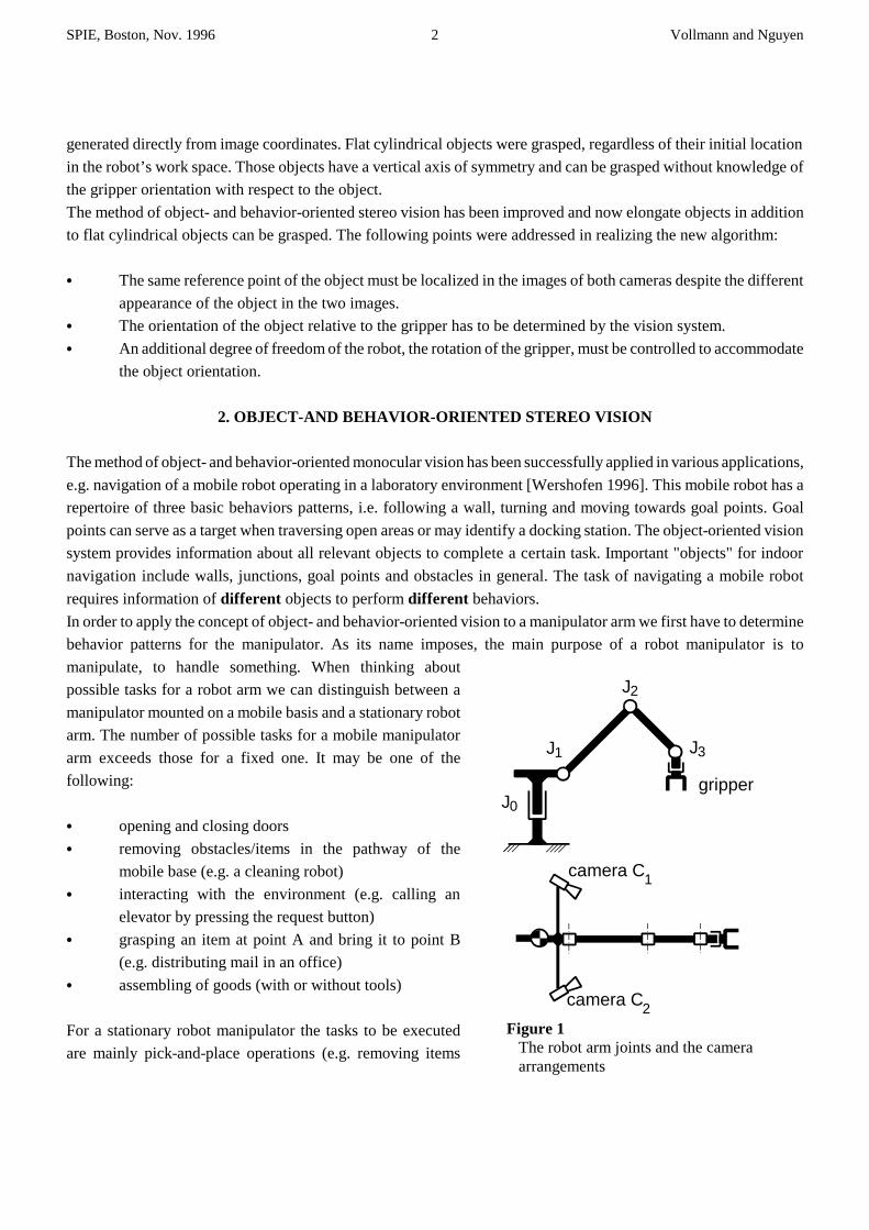
2Figure 1 The robot arm joints and the camera arrangements
generated directly from image coordinates. Flat cylindrical objects were grasped, regardless of their initial location
in the robot’s work space. Those objects have a vertical axis of symmetry and can be grasped without knowledge of
the gripper orientation with respect to the object.
The method of object- and behavior-oriented stereo vision has been improved and now elongate objects in addition
to flat cylindrical objects can be grasped. The following points were addressed in realizing the new algorithm:
C The same reference point of the object must be localized in the images of both cameras despite the different
appearance of the object in the two images.
C The orientation of the object relative to the gripper has to be determined by the vision system.
C An additional degree of freedom of the robot, the rotation of the gripper, must be controlled to accommodate
the object orientation.
2. OBJECT-AND BEHAVIOR-ORIENTED STEREO VISION
The method of object- and behavior-oriented monocular vision has been successfully applied in various applications,
e.g. navigation of a mobile robot operating in a laboratory environment [Wershofen 1996]. This mobile robot has a
repertoire of three basic behaviors patterns, i.e. following a wall, turning and moving towards goal points. Goal
points can serve as a target when traversing open areas or may identify a docking station. The object-oriented vision
system provides information about all relevant objects to complete a certain task. Important "objects" for indoor
navigation include walls, junctions, goal points and obstacles in general. The task of navigating a mobile robot
requires information of different objects to perform different behaviors.
In order to apply the concept of object- and behavior-oriented vision to a manipulator arm we first have to determine
behavior patterns for the manipulator. As its name imposes, the main purpose of a robot manipulator is to
manipulate, to handle something. When thinking about
possible tasks for a robot arm we can distinguish between a
manipulator mounted on a mobile basis and a stationary robot
arm. The number of possible tasks for a mobile manipulator
arm exceeds those for a fixed one. It may be one of the
following:
C opening and closing doors
C removing obstacles/items in the pathway of the
mobile base (e.g. a cleaning robot)
C interacting with the environment (e.g. calling an
elevator by pressing the request button)
C grasping an item at point A and bring it to point B
(e.g. distributing mail in an office)
C assembling of goods (with or without tools)
For a stationary robot manipulator the tasks to be executed
are mainly pick-and-place operations (e.g. removing items
SPIE, Boston, Nov. 1996 3 Vollmann and Nguyen
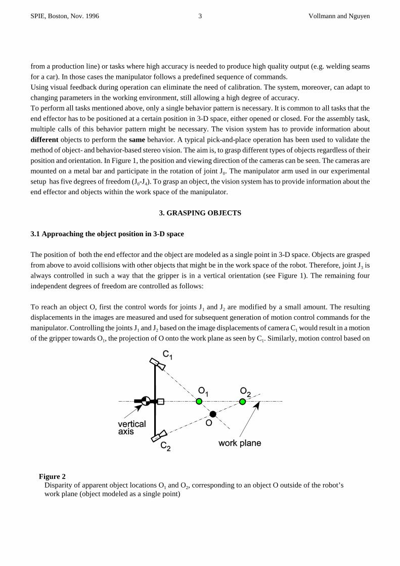
Figure 2 Disparity of apparent object locations O1 and O2, corresponding to an object O outside of the robot’s work plane (object modeled as a single point)
from a production line) or tasks where high accuracy is needed to produce high quality output (e.g. welding seams
for a car). In those cases the manipulator follows a predefined sequence of commands.
Using visual feedback during operation can eliminate the need of calibration. The system, moreover, can adapt to
changing parameters in the working environment, still allowing a high degree of accuracy.
To perform all tasks mentioned above, only a single behavior pattern is necessary. It is common to all tasks that the
end effector has to be positioned at a certain position in 3-D space, either opened or closed. For the assembly task,
multiple calls of this behavior pattern might be necessary. The vision system has to provide information about
different objects to perform the same behavior. A typical pick-and-place operation has been used to validate the
method of object- and behavior-based stereo vision. The aim is, to grasp different types of objects regardless of their
position and orientation. In Figure 1, the position and viewing direction of the cameras can be seen. The cameras are
mounted on a metal bar and participate in the rotation of joint J0. The manipulator arm used in our experimental
setup has five degrees of freedom (J0-J4). To grasp an object, the vision system has to provide information about the
end effector and objects within the work space of the manipulator.
3. GRASPING OBJECTS
3.1 Approaching the object position in 3-D space
The position of both the end effector and the object are modeled as a single point in 3-D space. Objects are grasped
from above to avoid collisions with other objects that might be in the work space of the robot. Therefore, joint J3 is
always controlled in such a way that the gripper is in a vertical orientation (see Figure 1). The remaining four
independent degrees of freedom are controlled as follows:
To reach an object O, first the control words for joints J1 and J2 are modified by a small amount. The resulting
displacements in the images are measured and used for subsequent generation of motion control commands for the
manipulator. Controlling the joints J1 and J2 based on the image displacements of camera C1 would result in a motion
of the gripper towards O1, the projection of O onto the work plane as seen by C1. Similarly, motion control based on
SPIE, Boston, Nov. 1996 4 Vollmann and Nguyen
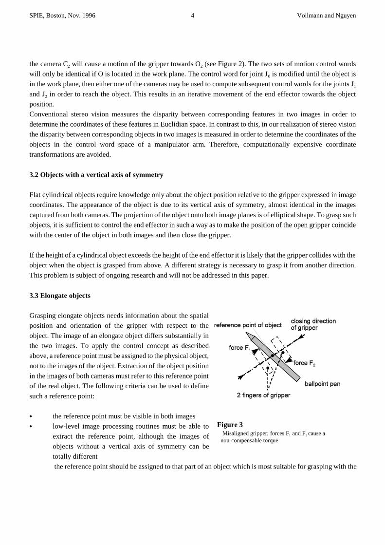
Figure 3 Misaligned gripper; forces F1 and F2 cause a non-compensable torque
the camera C2 will cause a motion of the gripper towards O2 (see Figure 2). The two sets of motion control words
will only be identical if O is located in the work plane. The control word for joint J0 is modified until the object is
in the work plane, then either one of the cameras may be used to compute subsequent control words for the joints J1
and J2 in order to reach the object. This results in an iterative movement of the end effector towards the object
position.
Conventional stereo vision measures the disparity between corresponding features in two images in order to
determine the coordinates of these features in Euclidian space. In contrast to this, in our realization of stereo vision
the disparity between corresponding objects in two images is measured in order to determine the coordinates of the
objects in the control word space of a manipulator arm. Therefore, computationally expensive coordinate
transformations are avoided.
3.2 Objects with a vertical axis of symmetry
Flat cylindrical objects require knowledge only about the object position relative to the gripper expressed in image
coordinates. The appearance of the object is due to its vertical axis of symmetry, almost identical in the images
captured from both cameras. The projection of the object onto both image planes is of elliptical shape. To grasp such
objects, it is sufficient to control the end effector in such a way as to make the position of the open gripper coincide
with the center of the object in both images and then close the gripper.
If the height of a cylindrical object exceeds the height of the end effector it is likely that the gripper collides with the
object when the object is grasped from above. A different strategy is necessary to grasp it from another direction.
This problem is subject of ongoing research and will not be addressed in this paper.
3.3 Elongate objects
Grasping elongate objects needs information about the spatial
position and orientation of the gripper with respect to the
object. The image of an elongate object differs substantially in
the two images. To apply the control concept as described
above, a reference point must be assigned to the physical object,
not to the images of the object. Extraction of the object position
in the images of both cameras must refer to this reference point
of the real object. The following criteria can be used to define
such a reference point:
C the reference point must be visible in both images
C low-level image processing routines must be able to
extract the reference point, although the images of
objects without a vertical axis of symmetry can be
totally different
the reference point should be assigned to that part of an object which is most suitable for grasping with the
SPIE, Boston, Nov. 1996 5 Vollmann and Nguyen
j F ' 0 � j M ' 0
available end effector
C the end effector of the manipulator arm should be able to grasp the object at the reference point without
changing the position or orientation of the object
The gripper approaches the reference point of the object as described in section 3.1 (make gripper position coincide
with reference point of the object). The position of the physical end effector is described by its tool center point
(TCP). It is an imaginary point that lies along the last wrist axis at a user specified distance from the wrist [Koren
1985]. Here the TCP is the spatial center between the gripper jaws. A ballpoint pen serves as the object to be
grasped. The reference point of the ballpoint pen lies on its rotational axis at a distance of half the object length from
where the rotational axis intersects the object. The image processing algorithms, however, cannot extract spatial
information from a two dimensional image. Therefore, tool center point and reference point of the object are
approximated in the images by the centroids of their projections onto the image plane of the left and right camera
image, respectively.
In order to align gripper and object, information about the current orientation of the gripper and the object has to be
extracted from the images. Ideally, the closing direction of the gripper is perpendicular to the object surface. Our
gripper is a two fingered parallel jaw type. The robot fingers consist of small flat plates. An optimal grasping of an
elongate object requires an exact alignment of the gripper with respect to the object. Figure 3 shows an example of
a misaligned gripper. The position of the end effector has been controlled in such a way that the tool center point of
the end effector coincides with the reference point of the object. When the gripper closes, the object is first touched
at two points. The two forces F1 and F2 result from the movement of both fingers of the gripper. These forces cause
a non-compensable torque and make the object rotating around its reference point. When the object rotates the
contact points finally become contact areas. If
the rotation stops and the ballpoint pen has been grasped. Other forces, such as friction, have intentionally been
omitted here to simplify the description of misalignment. To align the end effector with the object, joint J4 has to be
controlled appropriately. Joint J4 refers to the rotation of the gripper around its vertical axis. From its zero position
the gripper can be rotated in the range of -180° to +180°. Thus, two possible control words exist which make the
gripper aligned with the object. For efficiency reasons, the desired solution requires the smaller change of this joint
angle.
SPIE, Boston, Nov. 1996 6 Vollmann and Nguyen
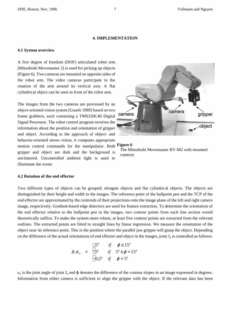
Figure 5 Snapshot from the right camera
Figure 4 Snapshot from the left camera
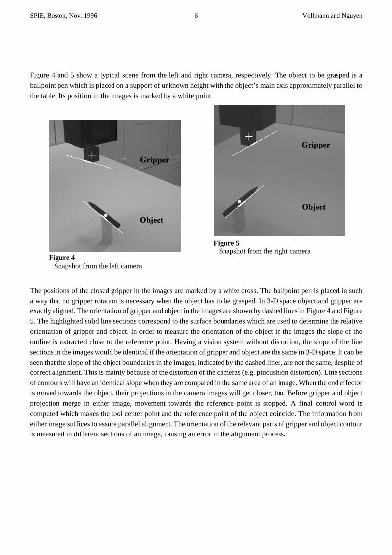
Figure 4 and 5 show a typical scene from the left and right camera, respectively. The object to be grasped is a
ballpoint pen which is placed on a support of unknown height with the object’s main axis approximately parallel to
the table. Its position in the images is marked by a white point.
The positions of the closed gripper in the images are marked by a white cross. The ballpoint pen is placed in such
a way that no gripper rotation is necessary when the object has to be grasped. In 3-D space object and gripper are
exactly aligned. The orientation of gripper and object in the images are shown by dashed lines in Figure 4 and Figure
5. The highlighted solid line sections correspond to the surface boundaries which are used to determine the relative
orientation of gripper and object. In order to measure the orientation of the object in the images the slope of the
outline is extracted close to the reference point. Having a vision system without distortion, the slope of the line
sections in the images would be identical if the orientation of gripper and object are the same in 3-D space. It can be
seen that the slope of the object boundaries in the images, indicated by the dashed lines, are not the same, despite of
correct alignment. This is mainly because of the distortion of the cameras (e.g. pincushion distortion). Line sections
of contours will have an identical slope when they are compared in the same area of an image. When the end effector
is moved towards the object, their projections in the camera images will get closer, too. Before gripper and object
projection merge in either image, movement towards the reference point is stopped. A final control word is
computed which makes the tool center point and the reference point of the object coincide. The information from
either image suffices to assure parallel alignment. The orientation of the relevant parts of gripper and object contour
is measured in different sections of an image, causing an error in the alignment process.
SPIE, Boston, Nov. 1996 7 Vollmann and Nguyen
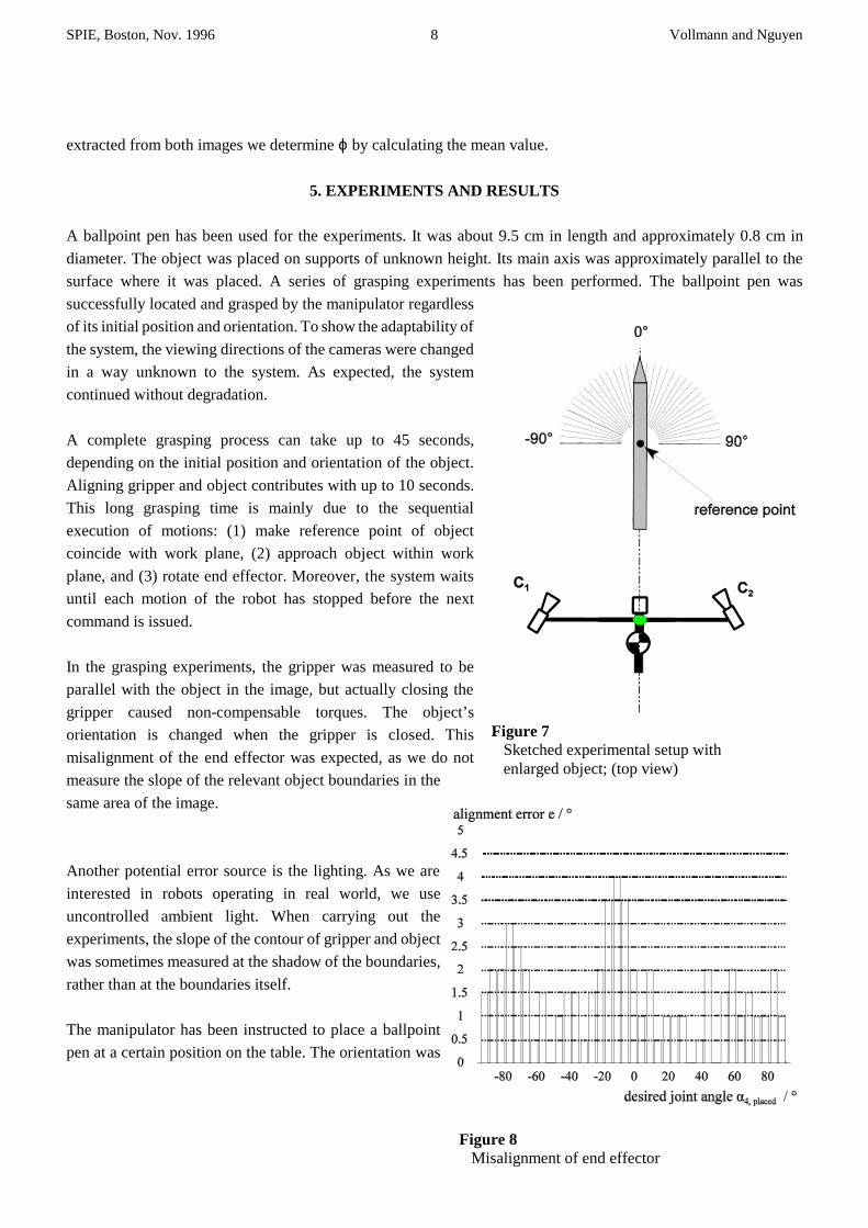
Figure 6 The Mitsubishi Movemaster RV-M2 with mounted cameras
∆ αϕ
ϕϕ
4
5 15
1 5 15
0 5 5
=° ≥ °° ° ≤ < °
° < °
if
if
if,
4. IMPLEMENTATION
4.1 System overview
A five degree of freedom (DOF) articulated robot arm
(Mitsubishi Movemaster 2) is used for picking up objects
(Figure 6). Two cameras are mounted on opposite sides of
the robot arm. The video cameras participate in the
rotation of the arm around its vertical axis. A flat
cylindrical object can be seen in front of the robot arm.
The images from the two cameras are processed by an
object-oriented vision system [Graefe 1989] based on two
frame grabbers, each containing a TMS320C40 Digital
Signal Processor. The robot control program receives the
information about the position and orientation of gripper
and object. According to the approach of object- and
behavior-oriented stereo vision, it computes appropriate
motion control commands for the manipulator. Both
gripper and object are dark and the background is
uncluttered. Uncontrolled ambient light is used to
illuminate the scene.
4.2 Rotation of the end effector
Two different types of objects can be grasped; elongate objects and flat cylindrical objects. The objects are
distinguished by their height and width in the images. The reference point of the ballpoint pen and the TCP of the
end effector are approximated by the centroids of their projections onto the image plane of the left and right camera
image, respectively. Gradient-based edge detectors are used for feature extraction. To determine the orientation of
the end effector relative to the ballpoint pen in the images, two contour points from each line section would
theoretically suffice. To make the system more robust, at least five contour points are extracted from the relevant
outlines. The extracted points are fitted to straight lines by linear regression. We measure the orientation of the
object near its reference point. This is the position where the parallel jaw gripper will grasp the object. Depending
on the difference of the actual orientations of end effector and object in the images, joint J4 is controlled as follows:
4 is the joint angle of joint J4 and ϕ denotes the difference of the contour slopes in an image expressed in degrees.
Information from either camera is sufficient to align the gripper with the object. If the relevant data has been
SPIE, Boston, Nov. 1996 8 Vollmann and Nguyen
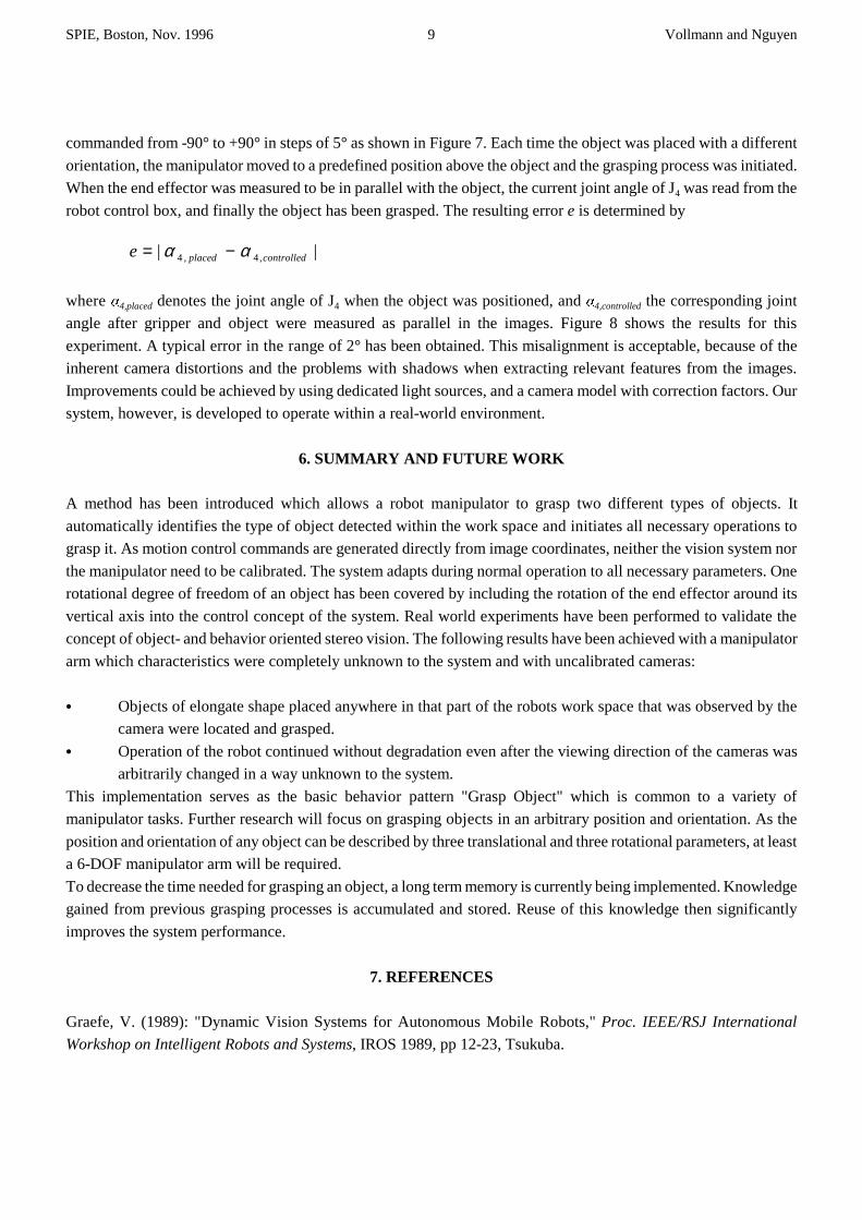
Figure 7 Sketched experimental setup with enlarged object; (top view)
Figure 8 Misalignment of end effector
extracted from both images we determine ϕ by calculating the mean value.
5. EXPERIMENTS AND RESULTS
A ballpoint pen has been used for the experiments. It was about 9.5 cm in length and approximately 0.8 cm in
diameter. The object was placed on supports of unknown height. Its main axis was approximately parallel to the
surface where it was placed. A series of grasping experiments has been performed. The ballpoint pen was
successfully located and grasped by the manipulator regardless
of its initial position and orientation. To show the adaptability of
the system, the viewing directions of the cameras were changed
in a way unknown to the system. As expected, the system
continued without degradation.
A complete grasping process can take up to 45 seconds,
depending on the initial position and orientation of the object.
Aligning gripper and object contributes with up to 10 seconds.
This long grasping time is mainly due to the sequential
execution of motions: (1) make reference point of object
coincide with work plane, (2) approach object within work
plane, and (3) rotate end effector. Moreover, the system waits
until each motion of the robot has stopped before the next
command is issued.
In the grasping experiments, the gripper was measured to be
parallel with the object in the image, but actually closing the
gripper caused non-compensable torques. The object’s
orientation is changed when the gripper is closed. This
misalignment of the end effector was expected, as we do not
measure the slope of the relevant object boundaries in the
same area of the image.
Another potential error source is the lighting. As we are
interested in robots operating in real world, we use
uncontrolled ambient light. When carrying out the
experiments, the slope of the contour of gripper and object
was sometimes measured at the shadow of the boundaries,
rather than at the boundaries itself.
The manipulator has been instructed to place a ballpoint
pen at a certain position on the table. The orientation was
SPIE, Boston, Nov. 1996 9 Vollmann and Nguyen
e placed controlled= −| |, ,α α4 4
commanded from -90° to +90° in steps of 5° as shown in Figure 7. Each time the object was placed with a different
orientation, the manipulator moved to a predefined position above the object and the grasping process was initiated.
When the end effector was measured to be in parallel with the object, the current joint angle of J4 was read from the
robot control box, and finally the object has been grasped. The resulting error e is determined by
where 4,placed denotes the joint angle of J4 when the object was positioned, and 4,controlled the corresponding joint
angle after gripper and object were measured as parallel in the images. Figure 8 shows the results for this
experiment. A typical error in the range of 2° has been obtained. This misalignment is acceptable, because of the
inherent camera distortions and the problems with shadows when extracting relevant features from the images.
Improvements could be achieved by using dedicated light sources, and a camera model with correction factors. Our
system, however, is developed to operate within a real-world environment.
6. SUMMARY AND FUTURE WORK
A method has been introduced which allows a robot manipulator to grasp two different types of objects. It
automatically identifies the type of object detected within the work space and initiates all necessary operations to
grasp it. As motion control commands are generated directly from image coordinates, neither the vision system nor
the manipulator need to be calibrated. The system adapts during normal operation to all necessary parameters. One
rotational degree of freedom of an object has been covered by including the rotation of the end effector around its
vertical axis into the control concept of the system. Real world experiments have been performed to validate the
concept of object- and behavior oriented stereo vision. The following results have been achieved with a manipulator
arm which characteristics were completely unknown to the system and with uncalibrated cameras:
C Objects of elongate shape placed anywhere in that part of the robots work space that was observed by the
camera were located and grasped.
C Operation of the robot continued without degradation even after the viewing direction of the cameras was
arbitrarily changed in a way unknown to the system.
This implementation serves as the basic behavior pattern "Grasp Object" which is common to a variety of
manipulator tasks. Further research will focus on grasping objects in an arbitrary position and orientation. As the
position and orientation of any object can be described by three translational and three rotational parameters, at least
a 6-DOF manipulator arm will be required.
To decrease the time needed for grasping an object, a long term memory is currently being implemented. Knowledge
gained from previous grasping processes is accumulated and stored. Reuse of this knowledge then significantly
improves the system performance.
7. REFERENCES
Graefe, V. (1989): "Dynamic Vision Systems for Autonomous Mobile Robots," Proc. IEEE/RSJ International
Workshop on Intelligent Robots and Systems, IROS 1989, pp 12-23, Tsukuba.
SPIE, Boston, Nov. 1996 10 Vollmann and Nguyen
Graefe, V., Ta, Q.-H. (1995): "An Approach to Self-learning Manipulator Control Based on Vision," Proc.
International Symposium on Measurement and Control in Robotics, pp 409-414, Smolenice.
Hollinghurst, N, Cipolla, R. (1994): "Uncalibrated stereo hand-eye coordination," Image and Vision Computing,
Volume 12/3, pp 187-192.
Koren, Y. (1985): "Robotics for Engineers," McGraw-Hill, New York.
Wershofen, K.P. (1996): Zur Navigation sehender mobiler Roboter in Wegenetzen von Gebäuden - Ein
objektorientierter, verhaltensbasierter Ansatz. Dissertation, Fakultät für Luft- und Raumfahrttechnik der Universität
der Bundeswehr München.
Yoshimi, B.H., Allen, P.K. (1994): "Active, uncalibrated visual servoing," IEEE International Conference on
Robotics and Automation, Volume 4, pp 156-161, San Diego, CA.
Related Documents