Abstract—This paper presents a methodology for trajectory control of single-link lightweight flexible manipulators. The objective is to control the trajectory of the tip position of the flexible-link manipulator in the presence of joint friction and output disturbances. Robust nonlinear approach is applied to guarantee system stability and to alleviate the degrading effects of uncertainties and nonlinearities presented in the dynamics of the system. Output redefinition is used to cancel the effects of the internal instability of the zero dynamic of the flexible- link. A drawback of this method, however, is that the controller is designed to track a new output trajectory. In fact, the difference between the tip position and new defined output could be significant and affects the tracking performance. To overcome this problem, a fuzzy compensator is employed. Simulation study and experimental results are presented to illustrate the performance of the proposed composite control strategy. I. INTRODUCTION UE TO several advantages of flexible-link manipulator systems in contrast to traditional rigid-link manipulators, such as energy efficiency, fast response, and higher ratio of payload to arm weight, these systems received a great deal of attention in the recent years. These advantages are vitally important in many engineering applications such as space arm manipulators and telesurgery operations. However, these advantages are gained at the price of increasing complexity of the system. Because of high nonlinearity of the system and existence of frictions and back-lash terms, modeling of the flexible link is complicated. Furthermore, model truncation involves in the modeling of the system, causes un-modeled dynamic in the mathematical model of the system. In these systems the trajectory of the tip could not be considered as the same of the joint trajectory. The input-output system is not minimum phase anymore and by using common controllers, asymptotic tracking of a desire tip trajectory is not possible. To overcome this problem several strategies are proposed. In our review these main strategies are classified in three groups. The first proposed method is based on getting feedback Hamed Ghazavi Khorasgani is with the Electrical Department of Amirkabir University of Technology, Tehran, Iran( h_gh@ aut.ac.ir) Naser Elmi Ghiasi is with the Mechanical Department of Amirkabir University of Technology, Tehran, Iran( nelmi @ aut.ac.ir) Ali Farshad is with the Mechanical Department of Amirkabir University of Technology, Tehran, Iran( alifarshad @ aut.ac.ir) Heidar Ali Talebi is with the Electrical Department of Amirkabir University of Technology, Tehran, Iran (corresponding author to provide phone: 00982164543340; fax: 00982166406469; e-mail: alit@ aut.ac.ir). from hub position instead of tip position. Consequently the input-output system is minimum phase. In this approach the trajectory of joint position is controlled and the vibration modes are stabilized [2]-[5].In [2] a hybrid controller is used to control joint position and velocity of two link flexible manipulator. The hybrid controller consists of a nonlinear controller which guarantees stability of the system and an adaptive neural network controller for compensating uncertainties and un-modeled dynamics effects. In [3] an adaptive nonlinear controller for a single flexible link manipulator is presented and Lyapunov method is used to guarantee asymptotical stability of the closed-loop system. In [4] feedback linearization method is utilized for trajectory tracking of uncertain flexible link and to improve the robustness of the proposed control strategy an adaptive neural fuzzy compensator is used as a parallel controller. In [5] the singular perturbation technique is employed to decompose the system dynamics into a fast and a slow subsystem and for each subsystem a controller is designed independently. A NN-based scheme is proposed to compensate saturation in both of the controllers. In the second proposed strategy output redefinition is utilized to solve the problem. In this method, because of the non-minimum phase behavior of the tip position, the output is selected as a new point [1], [6]-[7]. In [1], a neural network is employed for determining an appropriate output in the output redefinition process, and to achieve trajectory tracking a hybrid controller composed of a neural network tracking controller and a stabilizing PD controller are designed. In [6] the new output is selected as a point close to the tip position and Lyapunov Redesign Feedback Linearization (LRFL) approach is applied for tracking control of flexible-link in the presence of model uncertainties and disturbances. In [7] the desired reference trajectory is modified in the outer loop using synthesis based robust controller. In the inner loop the output is redefined as a conventional close to tip point and a Lyapunov Redesign Feedback Linearization (LRFL) approach is utilized for tracking the modified reference trajectory. The last group have employed smart materials, specifically, piezoelectric materials (PZT), in control of a single-link flexible manipulator [8]. This technique utilizes the property that under a control voltage, the piezoelectric material bonds to the flexible structure and produces a shear force that prevents the structural deformation. By using this method the system is not under actuated anymore and difficulties associated with the non-minimum phase behavior of the system will not arise. However, this method needs Nonlinear Robust Control of Flexible-link Manipulator with Fuzzy Compensator: Experimental Results Hamed Ghazavi Khorasgani, Naser Elmi Ghiasi, Ali Farshad and H.A.Talebi D 2011 2nd International Conference on Control, Instrumentation and Automation (ICCIA) 978-1-4673-1690-3/12/$31.00©2011 IEEE 993

Welcome message from author
This document is posted to help you gain knowledge. Please leave a comment to let me know what you think about it! Share it to your friends and learn new things together.
Transcript

Abstract—This paper presents a methodology for trajectory control of single-link lightweight flexible manipulators. The objective is to control the trajectory of the tip position of the flexible-link manipulator in the presence of joint friction and output disturbances. Robust nonlinear approach is applied to guarantee system stability and to alleviate the degrading effects of uncertainties and nonlinearities presented in the dynamics of the system. Output redefinition is used to cancel the effects of the internal instability of the zero dynamic of the flexible-link. A drawback of this method, however, is that the controller is designed to track a new output trajectory. In fact, the difference between the tip position and new defined output could be significant and affects the tracking performance. To overcome this problem, a fuzzy compensator is employed. Simulation study and experimental results are presented to illustrate the performance of the proposed composite control strategy.
I. INTRODUCTION UE TO several advantages of flexible-link
manipulator systems in contrast to traditional rigid-link manipulators, such as energy efficiency, fast response, and higher ratio of payload to arm weight, these systems received a great deal of attention in the recent years. These advantages are vitally important in many engineering applications such as space arm manipulators and telesurgery operations. However, these advantages are gained at the price of increasing complexity of the system. Because of high nonlinearity of the system and existence of frictions and back-lash terms, modeling of the flexible link is complicated. Furthermore, model truncation involves in the modeling of the system, causes un-modeled dynamic in the mathematical model of the system. In these systems the trajectory of the tip could not be considered as the same of the joint trajectory. The input-output system is not minimum phase anymore and by using common controllers, asymptotic tracking of a desire tip trajectory is not possible. To overcome this problem several strategies are proposed. In our review these main strategies are classified in three groups.
The first proposed method is based on getting feedback
Hamed Ghazavi Khorasgani is with the Electrical Department of
Amirkabir University of Technology, Tehran, Iran( h_gh@ aut.ac.ir) Naser Elmi Ghiasi is with the Mechanical Department of Amirkabir
University of Technology, Tehran, Iran( nelmi @ aut.ac.ir) Ali Farshad is with the Mechanical Department of Amirkabir University
of Technology, Tehran, Iran( alifarshad @ aut.ac.ir) Heidar Ali Talebi is with the Electrical Department of Amirkabir
University of Technology, Tehran, Iran (corresponding author to provide phone: 00982164543340; fax: 00982166406469; e-mail: alit@ aut.ac.ir).
from hub position instead of tip position. Consequently the input-output system is minimum phase. In this approach the trajectory of joint position is controlled and the vibration modes are stabilized [2]-[5].In [2] a hybrid controller is used to control joint position and velocity of two link flexible manipulator. The hybrid controller consists of a nonlinear controller which guarantees stability of the system and an adaptive neural network controller for compensating uncertainties and un-modeled dynamics effects. In [3] an adaptive nonlinear controller for a single flexible link manipulator is presented and Lyapunov method is used to guarantee asymptotical stability of the closed-loop system. In [4] feedback linearization method is utilized for trajectory tracking of uncertain flexible link and to improve the robustness of the proposed control strategy an adaptive neural fuzzy compensator is used as a parallel controller. In [5] the singular perturbation technique is employed to decompose the system dynamics into a fast and a slow subsystem and for each subsystem a controller is designed independently. A NN-based scheme is proposed to compensate saturation in both of the controllers.
In the second proposed strategy output redefinition is utilized to solve the problem. In this method, because of the non-minimum phase behavior of the tip position, the output is selected as a new point [1], [6]-[7]. In [1], a neural network is employed for determining an appropriate output in the output redefinition process, and to achieve trajectory tracking a hybrid controller composed of a neural network tracking controller and a stabilizing PD controller are designed. In [6] the new output is selected as a point close to the tip position and Lyapunov Redesign Feedback Linearization (LRFL) approach is applied for tracking control of flexible-link in the presence of model uncertainties and disturbances. In [7] the desired reference trajectory is modified in the outer loop using synthesis based robust controller. In the inner loop the output is redefined as a conventional close to tip point and a Lyapunov Redesign Feedback Linearization (LRFL) approach is utilized for tracking the modified reference trajectory.
The last group have employed smart materials, specifically, piezoelectric materials (PZT), in control of a single-link flexible manipulator [8]. This technique utilizes the property that under a control voltage, the piezoelectric material bonds to the flexible structure and produces a shear force that prevents the structural deformation. By using this method the system is not under actuated anymore and difficulties associated with the non-minimum phase behavior of the system will not arise. However, this method needs
Nonlinear Robust Control of Flexible-link Manipulator with Fuzzy Compensator: Experimental Results
Hamed Ghazavi Khorasgani, Naser Elmi Ghiasi, Ali Farshad and H.A.Talebi
D
2011 2nd International Conference on Control, Instrumentation and Automation (ICCIA)
978-1-4673-1690-3/12/$31.00©2011 IEEE 993

significant changes in the actuator and the flexible link structure which are not feasible always.
In this work, robust nonlinear control approach is utilized in order to guarantees small tip tracking error in uncertain situations. The main task of the robust nonlinear control is to guarantee system stability in the presence of uncertainties and un-modeled dynamics. To avoid difficulties associated with unstable zero dynamic, the output is selected as a close point to the tip position. And to compensate the error which imposes to the system by the output redefinition a fuzzy compensator is introduced. This fuzzy compensator gets feedback from the original output and generates an additive control term which lowers the tip tracking error. It should be mentioned that the fuzzy compensator term adds to the controller only when the absolute tracking error becomes less than a certain small amount.
This paper is organized as follows. Section II discusses the dynamic modeling and output redefinition method. Section III introduces the structure of the proposed robust controller and stability analysis. Section IV proposes a fuzzy compensator for alleviating the undesired effects of output redefinition on tracking performance and demonstrates the switching strategy. Simulation results are presented in Section V which is followed by experimental results in Section VI. The last section concludes the paper.
II. DYNAMIC MODELING Nonlinear dynamic modeling of flexible link manipulator
can be done with assuming each link is a beam, so the theories for elastic beam can be used in the modeling process. Regarding high ratio of length to width and negligible amount of shear deformation and rotary inertia, Euler Bernoulli beam theory can be used for modeling the flexible link. One of the methods, which can be used for driving the equation of motion for flexible structures such as the flexible link, is lagrangian approach. Nonlinear dynamic equation of single link flexible manipulator is derived by recursive lagrangian [1], finally the equation of motion given by:
1 1 1
2 2 2
( , ) ( , , , )( , )
0( , ) ( , , , )
cf h F f uM
f h K F
θ θ θ θ δ δ θθθ δ
δ θ θ θ θ δ δ δ δ
+ + ++ =
+ + +
(1)
Where θ is the hub angle, δ is a 1n× vector of deflection variables. 1 2 1, ,f f h and 2h are terms due to coriolis and centrifugal accelerations. 1F and 2F are positive diagonal matrix’s due to internal damping and hub damping respectively, and cf is coulomb friction. M is a Positive definite mass matrix and K is a Positive definite diagonal stiffness matrix, also u is the control torque exerts on the hub.
By defining: 1( , ) ( , )H Mθ δ θ δ−= (2)
One can rewrite (1) as:
1 1 1
2 2 2
( , ) ( , , , )( , )
( , ) ( , , , )cu f h F f
Hf h K F
θ θ θ θ δ δ θθθ δ
δ θ θ θ θ δ δ δ δ− − − −
=− − − −
(3)
The goal of the controller is to control the flexible link
end point position. Therefore the output can be defined as [1]:
( , )output
W L ty
Lθ= +
(4) where ( , )W x t , is deflection of the flexible link at point x
along length of the beam and t is the time. Deflection of the beam at arbitrary point and time can be defined by mode expansion theorem [9] and given by:
1
( , ) ( ) ( )n
i ii
W x t x tφ δ=
=
(5)
in (5) n is the number of mode shapes considered in modal expansion. As well as ( )i xφ is a mode shape function related to deflection variable ( )i tδ . The system has non-collocated and non-minimum phase nature consequently the internal dynamic of this system is unstable. Output redefining method presented in [9] to solve the problem. In this method, a new output defined near the tip position to transform the nature of problem to minimum phase. Redefined output can be defined as:
( , ) 1 1redefW L t
y whereL
θ α α= + − < < (6)
for 1α = , the output becomes the tip position and for 0α = it is the hub position. In [9] the condition forα ,
which the input-output system is minimum phase is derived. This condition is given by:
max max[ 1, ], 1stableα α α∈ − < (7) Note that the bigger α has a smaller tracking error,
because the redefined output is more close to tip point. Hence to reducing the tracking error maxα should be used in (4). maxα can be calculated by the procedure presented in [9].
In this paper, we assumed two first mode shapes of flexible link in modeling. The Quanser single flexible link manipulator experimental platform is used to implementing the controller. The physical and geometrical parameters used in modeling phase are tried to be same as Quanser platform parameters.
III. CONTROL STRATEGY This section presents the robust nonlinear control
structure for tip-position tracking control of a exible-link manipulator. Sliding mode is a well-known robust nonlinear controller employed to control uncertain rigid manipulators. Although it can’t be utilized for flexible-link manipulator since the zero dynamic corresponding to main output is not stable. Consequently, some sort of output redefinition should be applied to make the method practical for the flexible links. Based on the previous discussions, one can define the new output of the flexible link as:
994

( , )red ef s tab le
W L ty
Lθ α= + (8)
Note that stableα increases by increasing the payload [1]. Therefore, in variable or uncertain payload situation, to avoid zero dynamic instability, stableα should be calculated for minimum amount of the payload. Since the relative degree of the system is “2”, one can derive the dynamic of the redefined output as:
1 1 2 2( ) ( )redef stable
L Ly
Lφ δ φ δθ α × + ×
= + (9)
where L is the length of the flexible link. 1δ is the first deflection variable and 1( )Lφ is the first mode shape related to it. 2δ is the second deflection variable and 2 ( )Lφ is the second mode shape related to it. Note that for the sake of simplicity just the two first mode shapes and the deflection variables related to them are considered. By substituting parameters from Table I and θ from (3) in (9) one can rewrite the redefined output in the following form:
redefy f g u= + × (10)
where f and g are uncertain functions. Suppose that the
nominal knowledge about f and g is represented by f and g respectively. Our proposed structure for controller is:
1 ( ( ) ( ))d redef d redef du y y y y y fg
σ= − − − − − +
(11)
where dy is the reference trajectory profile for the redefined output and its derivatives are presented by dy and dy . σ is an additional term, designed to asymptotically stabilize the system in the presence of model uncertainties. By substituting (11) in (10) and by using some algebraic manipulations, it may be shown: ( ) ( ) ( )redef d redef d redef dy y y y y y γ σ− − − − − = + (12)
where γ is a bounded uncertain term, with the upper bound ρ . γ ρ≤ (13)
Let us definedere f d
redef d
y ye
y y
−=
−, and define Lyapunov
function TV e Pe= .where P is a positive definite matrix satisfying the Lyapunov equation:
TA P PA Q+ = − (14)
for the Hurwitz matrix A and some positive definite matrix Q .
It can be easily seen that 0V ≤ satisfies by choosing σ as:
[ ][ ] [ ]0 1
0 1 00 1
0
Peif Pe
Pe
else
ρσ
− >=
(15)
To avoid chattering, which is harmful for the actuator, we chose σ as:
[ ][ ] [ ]
[ ]
0 10 1
0 1
0 1
Peif Pe
Pe
Peelse
ρ εσ
ρε
− >
=
−
(16)
where ε is a small positive number.
IV. FUZZY COMPENSATOR Avoiding the problems associated with the non-minimum
phase behavior of the tip position such as zero dynamic instability, the output is selected as a point close to the tip.
It is illustrated in the previous section that this new output follows the reference trajectory by employing the nonlinear robust controller. However, there is always some difference between the new output and the tip position, which imposes an error to the tracking performance. To decrease this tracking error a fuzzy compensator is considered in the control strategy. The fuzzy compensator gets feedback from the original output and generates an additive control term to decrease trajectory error. This term is considered only when the absolute error is less than some small certain amount. The effectiveness and capabilities of our proposed strategy are demonstrated through extensive simulation and experimental studies. The schematic of the proposed control strategy is shown in Fig. 1
In Fig. 1 su is the output of the switching strategy is given as follows:
1
0ref
s
ref
if y yu
if y y
α
α
− <=
− ≥
(17)
where α is a positive constant. Fu is the output of the fuzzy
system and c s Fu u u= × is the compensator term.
V. SIMULATION RESULTS In this section, the contribution of the fuzzy compensator
is presented by providing simulation results for system tracking performance with and without the fuzzy compensator. Moreover, the simulation results are presented to demonstrate the performance of the proposed method in the presence of model uncertainty and disturbance. The
Fig. 1. schematic of the control strategy
995
simulations are performed on a Quanser single flexible link manipulator model. Table I illustrates system nominal parameters.
A. Fuzzy compensator contribution In this simulation, the effectiveness of the fuzzy
compensator is evaluated. Fig. 2 represents the tracking performance by considering the fuzzy term in the controller and without it.
This figure clearly shows improvements achieved in the responses of the controlled system when the fuzzy compensator is used.
Fig. 2. Tracking performance with and without the fuzzy compensator
B. Robustness study In this part of the simulation study, the robustness of the
proposed control strategy is presented. To illustrate the performance of the control strategy in the presence of model uncertainty, in the first simulation 20% uncertainty is add to matrix M, in the second simulation the same amount of uncertainty is subtracted from the matrix M and in the last case 20% additive uncertainty is considered in matrix F. The results are shown in Fig. 3.
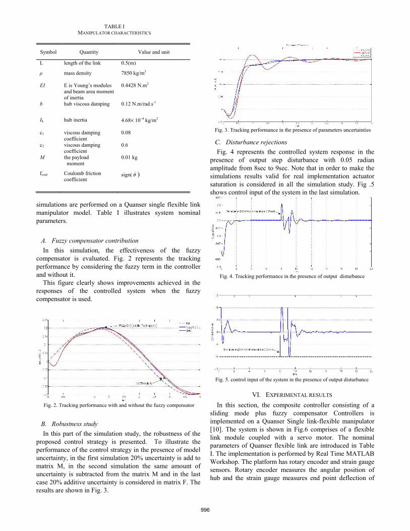
Fig. 3. Tracking performance in the presence of parameters uncertainties
C. Disturbance rejections Fig. 4 represents the controlled system response in the
presence of output step disturbance with 0.05 radian amplitude from 8sec to 9sec. Note that in order to make the simulations results valid for real implementation actuator saturation is considered in all the simulation study. Fig .5 shows control input of the system in the last simulation.
Fig. 4. Tracking performance in the presence of output disturbance
Fig. 5. control input of the system in the presence of output disturbance
VI. EXPERIMENTAL RESULTS In this section, the composite controller consisting of a
sliding mode plus fuzzy compensator Controllers is implemented on a Quanser Single link-flexible manipulator [10]. The system is shown in Fig.6 comprises of a flexible link module coupled with a servo motor. The nominal parameters of Quanser flexible link are introduced in Table I. The implementation is performed by Real Time MATLAB Workshop. The platform has rotary encoder and strain gauge sensors. Rotary encoder measures the angular position of hub and the strain gauge measures end point deflection of
TABLE I
MANIPULATOR CHARACTERISTICS
Symbol Quantity Value and unit
L length of the link 0.5(m)
mass density
7850 kg/m3
EI E is Young’s modules and beam area moment of inertia
0.4428 N.m2
b hub viscous damping 0.12 N.m/rad.s-1
Ih hub inertia 4.68× 10⁻⁴ kg/m2
c1 viscous damping coefficient
0.08
c2 viscous damping coefficient
0.6
M the payload moment
0.01 kg
fcoul Coulomb friction coefficient
sign( θ )
996

the flexible link, so angular position of the tip point can be calculated.
For studying the performance of the designed controller
on actual platform, two different reference trajectory signals are exerted as the input. The first reference trajectory is the step function and the second one is a sine wave function. The results are shown in the following figures. As it is evidence in Fig. 7 the controller performance in tracking of step input is acceptable, of course the small oscillations in the result is due to differences between actual platform parameters and nominal model. In fact the presented controller has a high robustness respect to model uncertainties. Furthermore the non-minimum-phase and delayed nature of the system can be detected in the Fig. 7.
Fig. 7. Experimental output of tip point position respect to step input
Due to importance of tracking time varying references in applications of flexible link manipulators, the performance of controller in tracking of sine wave is plotted in Fig. 8. As can be seen in this figure the controller performance in tracking of sine shape input has an attractive behavior, at the beginning time due to mechanical delay and actuator saturation the tracking error is big, but in the following the controller shows a great tracking performance.
Fig. 8. Experimental output of tip point position respect to sine shape
reference trajectory
VII. CONCLUSIONS A hybrid control strategy for tracking control of flexible
link manipulator has been proposed in this paper. The globally stable hybrid controller has been developed consists of a sliding mode controller and a fuzzy compensator. The undesired effect of output redefinition has lessened down by using fuzzy compensator. Extensive simulation results performed on a single flexible link are presented to illustrate the considerable capability of the proposed composite method in trajectory tracking of flexible link manipulator in the presence of un-modeled dynamic and disturbances. Finally the effectiveness of our proposed hybrid control strategy has demonstrated and validated in real situation through experimental studies.
ACKNOWLEDGMENT Feasibility of controller implementation on Quanser
platform is prepared by Dr.Naraghi’s Automatic control Laboratory in Mechanical Engineering Department of AmirKabir University of Technology.
REFERENCES [1] H. A. Talebi , K. Khorasani and R. V. Patel ,” Tracking control of a
flexible-link manipulator using neural networks: experimental results”,J. Robotica , volume 20, pp. 417–427(2002)
[2] A.R. Maouchem and M. Attari, “Hybrid Control Strategy for Flexible Manipulators”, ISIE 2007. IEEE International Symposium on Industrial Electronics, ISIE 2007,pp 50-55(2007)
[3] R.Fareh, Mohamad Saad and Maarouf.Saad ,”Adaptive Control for a Single Flexible Link Manipulator Using Sliding Mode Technique”, 6th International Multi-Conference on Systems, Signals and Devices, IEEE(2009)
[4] V.M.Hung and U.J.Na,”Adaptive Neural Fuzzy Control for Robot Manipulator Friction and Disturbance Compensator”, International Conference on Control, Automation and Systems, COEX, Seoul, Korea(2008)
[5] W.Gao, R.R. Selmic and F.L. Lewis,” Robust Composite Saturation Compensation for a Single Flexible Link Using Neural Networks”, Proceedings of the IEEE International Symposium on Intelligent Control, Limassol, Cyprus(2005).
[6] S.F. Atashzar, H.A. Talebi, F. Towhidkhah and M. Shahbazi” Tracking Control of Flexible-Link Manipulators Based on Environmental Force Disturbance Observer” 49th IEEE Conference on Decision and Control December 15-17, 2010
[7] S. F. Atashzar, H.A. Talebi, M.J. Yazdanpanah and F.Towhidkhah “Tip Position Tracking of Flexible-Link Manipulators Based on Online Robust Trajectory Modification” IECON 2010 - 36th Annual Conference on IEEE Industrial Electronics Society
Fig. 6. Experimental setup
997

[8] Dong Sun , James K. Mills, Jinjun Shan, S.K. Tso “A PZT actuator control of a single-link flexible manipulator based on linear velocity feedback and actuator placement” Mechatronics 14 (2004) 381–401
[9] H. A. Talebi, R. V. Patel, K. Khorasani, “Control of Flexible-Link Manipulators Using Neural Networks,” Lecture Notes in Control and Information Sciences, No. 261, Springer, (2001)
[10] Quanser Consulting Inc. (1998). Flexible link Experiment Manual.
998
Related Documents