9 State of New Mexico Energy, Minerals and Natural Resources Department Susana Martinez z^fNE Governor /$Hi[~ I 7 ^ & David Martin jami Bailey, Division Director \J(0~^Zf Cabinet Secretary-Designate Oil Conservation Division 1 L^V,- Brett F. Woods, Ph.D. \TV Deputy Cabinet Secretary ^^£RVA? New Mexico Oil Conservation Division approval and conditions listed below are made in accordance with OCD Rule 19.15.7.11 and are in addition to the actions approved by BLM on the following 3160-3 APD form. )ate: ^//j/// Operator Signature Date: Well information; . . „ . Operator EAJC/^A , Well Name and Number /^Jc/t'.Tb C/Y'2Y0Y ffO^n API# 3 d *0^r-3rrS3 , Section/ 1 / , Township X L I QfS, Range (f E/(0 Conditions of Approval: ^ ^ . , j I t kAitjl C»\/&-~ (See die below checked and handwritten conditions) / / /df Q J xi Notify Aztec OCD 24hrs prior to casing & cement. I f f I ¥ Hold C-104 for directional survey & "As Drilled" Plat 1 o Hold C-104 for NSL, NSP, DHC "kfi *>*f (TAJI^ ^ o Spacing rule violation. Operator must follow up with change of status notification on other well to be shut in or abandoned o Regarding the use of a pit, closed loop system or below grade tank, the operator must comply with the following as applicable: • A pit requires a complete C-144 be submitted and approved prior to the construction or use of the pit, pursuant to 19.15.17.8.A • A closed loop system requires notification prior to use, pursuant to 19.15.17.9.A • A below grade tank requires a registration be filed prior to the construction or use of the below grade tank, pursuant to 19.15.17.8.C o Once the well is spud, to prevent ground water contamination through whole or partial conduits from the surface, the operator shall drill without interruption through the fresh water zone or zones and shall immediately set in cement the water protection string ^ Oil base muds are not to be used until fresh water zones are cased and cemented providing isolation from the oil or diesel. This includes synthetic oils. Oil based mud, drilling fluids and solids must be contained in a steel closed loop system. NMOCD Approved by Signature Date 1220 South St. Francis Drive • Santa Fe, New Mexico 87505 Phone (505) 476-3460 • Fax (505) 476-3462 • www.emnrd.state.nm.us/ocd

Welcome message from author
This document is posted to help you gain knowledge. Please leave a comment to let me know what you think about it! Share it to your friends and learn new things together.
Transcript
9
State of New Mexico
Energy, Minerals and Natural Resources Department
Susana Martinez z^fNE Governor / $ H i [ ~
I 7 & David Martin jami Bailey, Division Director \J(0~^Zf Cabinet Secretary-Designate Oil Conservation Division 1 L ^ V , -
Brett F. Woods, Ph.D. \ T V Deputy Cabinet Secretary ^ ^ £ R V A ?
New Mexico Oil Conservation Division approval and conditions listed below are made in accordance with OCD Rule 19.15.7.11
and are in addition to the actions approved by BLM on the following 3160-3 APD form.
)ate: ^ / / j / / / Operator Signature Date: Well information; . . „ . Operator EAJC/^A , Well Name and Number /^Jc/t'.Tb C/Y'2Y0Y ffO^n
API# 3 d * 0 ^ r - 3 r r S 3 , Section/1/ , Township X L I QfS, Range ( f E / (0
Conditions of Approval: ^ ^ . , j I t kAitjl C»\/&-~ (See die below checked and handwritten conditions) / / /df Q J
xi Notify Aztec OCD 24hrs prior to casing & cement. I f f I
¥ Hold C-104 for directional survey & "As Drilled" Plat 1
o Hold C-104 for NSL, NSP, DHC " k f i *>*f ( T A J I ^ ^ o Spacing rule violation. Operator must follow up with change of status notification on other well
to be shut in or abandoned
o Regarding the use of a pit, closed loop system or below grade tank, the operator must comply with the following as applicable:
• A pit requires a complete C-144 be submitted and approved prior to the construction or use of the pit, pursuant to 19.15.17.8.A
• A closed loop system requires notification prior to use, pursuant to 19.15.17.9.A • A below grade tank requires a registration be filed prior to the construction or use of the
below grade tank, pursuant to 19.15.17.8.C o Once the well is spud, to prevent ground water contamination through whole or partial conduits
from the surface, the operator shall drill without interruption through the fresh water zone or zones and shall immediately set in cement the water protection string
^ Oil base muds are not to be used until fresh water zones are cased and cemented providing isolation from the oil or diesel. This includes synthetic oils. Oil based mud, drilling fluids and solids must be contained in a steel closed loop system.
NMOCD Approved by Signature Date
1220 South St. Francis Drive • Santa Fe, New Mexico 87505 Phone (505) 476-3460 • Fax (505) 476-3462 • www.emnrd.state.nm.us/ocd

Form 3 ICO-3 (March 2012) APR 14 20U
UNITED STATES DEPARTMENT OF THE INTERIOR BUREAU OF LAND MANAGEMENT, . . .
Gwecu of Lend Marie APPLICATION FOR PERMIT TO DRILL OR REENTER
5. Lease Serial No.
Fcrrninrjton Role! Ofcu6589
la. Typcofwork: 0 D R I L I . •RFKNTFR
lb. Type of Well: [ 7 ] Oil Well QCnis We'll QOlher [ / ] Single /.one | ~ l Multiple Zo.
:=PeTrdi
2. Name of Operator Encana Oil & Gas (USA) Inc.
3a. Address 370 17th Street, Suite 1700, Denver, CO 80202
3h. I'hone No. limlnde aiva axle)
720-876-3533
4. Location of Well tRc'imt location clearly and in acconhwee with am Sitttv rayw>vjffwi/.v.*>
Al surface 1393' FSL and 29' FWL in Section 14, T24N, R8W
At proposed prod, zone 430' FSL and 330' FWL in Section 15, T24N, R8W
14. Distance in miles and direction from nearest town or post ollicc* +/- 47.1 miles from the intersection of US Hwy 64 & US Hwy 550 in Bloomfield, NM
U. Distance from proposed* SHL is 29' from West lease line location lo nearest property or lease line, ft. (Also to nearest drig. unit line, if any)
IS. Distance from proposed location* E s c r i t o L 1 4 . 2 4 0 8 02H is lo nearest well, drilling, completed. ., ~ n , c . o u , applied for. on this lease. It. + / " 3 0 E o f S H L
21. Hlcvaiinns (Show whether DF. KDD. RT. GL, etc.) GL6896' KB 6912'
l(i. No. of acres in lease NM 16589- 1480 acres
19. I'roposed Depth
5683' TVD/10602' MD
FORM APPROVED OMDNo.l004-0l.17
Expires October .II. 24)I-1
"'fiJiifJiidinn. Allolce or Tribe Name N/A
If Unit or CA Atircciucnl. Name and No.
8. Lease Name and Well No. Escrito L14-2400 03H
9. AIM Well No.
30-Q^S- 35S3B IO. Field and Pool, or F.xploiatory
Escrjte^Gallup (associated) ed) tfXrf&sf&id I I . Sec.. T. R. M. ur lllk.and Survey or Area
Section 14, T24N, R8W NMPM
12. County or PSrVsh San Juan
1.1. State NM
17. Spacing Unit dedicated to this we
320 acres S/2 Section 15
20. HLM/HIA HOIKI No. on file
COB-000235 'JUL I a 20!4 22 Approximate dale work will start*
09/28/2014
23 Fslimaled duration
20 Days
24. Aiuichniciiis
Ilie following, completed in accordance wilh the rei|iiiiements of Onshore Oil and Gas Order No. I . must Iv attached to this form:
1. Well plat certified by a registered surveyor. 2. A Drilling Plan. 3. A Surface Use Plan (if Ihe location is 011 National Forest System Lands, the
SUPO must he filed wilh the appropriate Forest Service Office).
4. liond to cover the operations unless covered by an existing bond on file (see Item 20 above).
5. Operator certification 6. Such other site specific information andfor plans as mav be required bv the
BLM.
25. Signature Name tl'i-intalflypal) Kalie Wegner
Tille
Name (Printed/Typed! Date /
Application approval does nol warrant or certify that the applicant holds legal or equitable title to those rights in the subject lease which would entitle Ihe applicant lo conduct operations thereon. Conditions of approval, if any, are attached.
Title IS U.S.C. Section 1001 and Tide 43 U.S.C. Section 1212. make ila crime for any person knowinglv and willfully to make lo anv department or agency ofthe United tflCfisWctloiE OF THIS
A C T I O N DOES N O T R E L i t v i - . tm:- >••>••••-•— — 1
I me in VJ.i.L. .xenon 1001 anu 1 uie u.3.c. oeeuoii 11 inaKe 11 a ciiiue 101 any peison Mioumvay anu mniuuv Slates any false, fictitious or fraudulent Slalemc^ ^ S T j j f t ' ^ ^ ^ j j j y 1 ) ^ (g^i'^'^hjnyjtrjuyi'MlciiSiE OJ^TT
m= "(Instructions on page 2) (Continued on page 2) ' n>- 1 — - , -\- m > i c o M G O P E ^ 1 0 OPERATOR FROM OBTAINING A.\> O 1 > •• '<
. , . T H O & f t R E S S S S AUTHORIZATION REQUIRED FOR OPERATIONS This action is subject to technical COMPLIANCE W ^ ^ P U F N T S " ON FEDERAL AND INDIAN LAN Da a n d procedural review pursuant to
"ftCNERAL. REQy»« E W t l i r i 43 CFR 3165.3 and appeal w pursuant to 43 CFR 3165.4

1628 II ffrmxS ltr., Bofctta GS340 Ftaat (STO) GSQ-01G1 ttan (8J6) CSD-OTS)
flffljasia n SU a S*J«6 31. Me**, DJ1 8EB0 Ptaoen CSTB) f«D-lS83 I t a (BJB) 74Q-GTB0
1000 B9 B n t HaV. aafao. M l 87416 VfcGCK (80S) G34-C1TG Rm (BUS) 634-0110
itso & St. fnseis Br, Santa to m erao ' 13) ffrO-0460 fern (B08) 476-0SC3
State o? New Meidco Bnoray. Minorolo SI Natural Rooouraoo Dopa
Pom C-108 R loBd avasiuot I, 8011
m n Submit one copy to apn
Arrc 14 2014 MotHotomoo OIL CONSERVATION DIVISION 1220 South St. Fraaols Dr.
Saata IPs, MM 87509 Fii."iTTi'f1',tO'>Fi'-.Jwss.R7 «, i , ^ E^SMENDED REPORT Bureau of LKdf&iic.-v WELL LOCATION AND ACREAGE DEDICATION PLAT
'API Kumtgff "Pool Cads y ° Pool Home X") / f ) •
ESCRITj*-QAU.UP (ASSOCIATED) / J L l f t i r U' /v 4 Pro porty Cedo "ProysTty Heme / >
ESCRITO L14-2408
0 troll Mumbor
03H 'OOBID No.
282327 "Operator Namo
ENCANA OIL & CAS (USA) INC.
"Qorotlon
8868.0' 10 Surface Location
UL or lot no.
L BssUea
14 24N Kongo
SW tt(3a Pool from too
1303* H«!ta/&aa& lino
SOUTH Coot frost tea
28' teyWest Uao
WIST Sonnfsj' SAN JUAN
"Bottom Hole Location II Different From Surface UL or lot no.
M Section
13 24N Bongo
8W Lot Ida Pool from tho
430* North/South lino
SOUTH
Pest from tho
330'
Bost/tfoot lino WEST
County SAN JUAN
» Dedicated toeo PROJECT AREA 320.00 ACRES - S/2 SEC. 19
"Joint or Infill * ConeoUdatlon Code "Order Ho.
NO ALLOWABLE WILL BE ASSIGNED TO THIS COMPLETION UNTIL ALL INTERESTS HAVE BEEN CONSOLIDATED ie OR A NON-STANDARD UNIT HAS BEEN APPROVED BY THE DIVISION
1 LAT. 30314283* N LONO. 107.878220* LAT. 38.314273* N LONO. 107.877810*
2 LAT. 38J070BO* N LONO. 107.878378* LAT. 38J07048* N LONO. 107.87778T
N 68*33'39" W
N earaa* w
(NADU) W (NAD8S) (NA027) W (NAD27)
(NA083) W (NADU) (NA027) t l (NA027)
5201.93' (M) B2O4.10> (R)
SLAT. 38.313971* N LONO. 107.880323' LAT. 38.313888* N LONO. 107.889813'
4 LAT. 38.308321' N LONO. 107.880813' LAT. 38.308808* N LONO. 107.660083*
(NADU) W (NADU) (NAD27) W (NAD27)
(NADU) W (NADU) (NA027) W (NA027)
S 89*33*28* W
S 8tf J7* W
S182.88' (M)
ai04,W (P.)
i • • -i •.•'-'j-rtfej iT rrAi.' fau. • ! ' .
N^04'38^W|^ ~J&TiJ&~~~
—1 — 14 HELL n M I LAT. 38.310840- N (NAD83) LONG. 107.880486* W (NADU) LAT. 38.310838* N (NAD27) LONO. 107.689888* W (NAD27)
N 89-04'38" W N 8701' W
BOTTOM HOLE LAT. 38308229* N (NAD83) LONO. 107.877234- W (NADU) LAT. 38.3082ir N (NA027) LONO. 107.876823* W (NAD27)
3237.39* (M) 8133.1 V (R)
S 89-28*19" W 3 6734' W
5248.09' 6240.'
4
2 •
IS 3
n q
ENTRY POINT LAT. 38.308017- N (NAOU) LONO. 107.661717* W (NADU) LAT. 36.308005- N (NAD27) LONG. 107.881107* W (NA027)
» OPERATOR CERTIFICATION / Amity ccrf-tfr that t\o information contained Aorrin to frva and complete to tho tott of bnowledqo and tetiof, md (Aal ttti AT cnbaKm oUAor oums a tuorfcfaig tnfavwt or tmioacsd min«rai Inlfratf Cn (A* tend Cndudfrv; (Aa jmpond tottam haU location or haa a tigAI (o dHU Ma wtii oi IMo location pxtrvxumi to a contract wiiA an ewn*r a/ sueA a mfaml or uwrMr fntout or to a xnttmtary pooling GgritTptnl or o oomsnilsory pvoHryj orfar htntofori tntmdUni Ou d-Ufcrtoa
u Katie Wegrie^
Printed llama ~ K a t i e . W e g n e r e e n c a n a . c o m
SURVEYOR CERTIFICATION / harvby enHftf that the woli location thovm on this ptai wot ptoftod from fiald nalaa of actual ourvaya modi by ma cr xsndar my supervision and lAoJ tho soma ia two and cornel (o the 6otl oj my odia/.
DECEMBER 3, 2013 Dato of Qtsnof
and 8aaj^ii^Pn>fwrtiiTMl Sompo".
D AVI D R D 5 S E L L Certlfimto Bambsr 10201
S h e e t A

Escrito L14-2408 03H SHL: NWSW14 24N8W
1393 FSL 29 FWL BHL: SWSW15 24N8W
430 FSL 330 FWL San Juan, New Mexico
Encana Oil & Gas (USA) Inc. Drilling Plan
1. ESTIMATED TOPS OF GEOLOGICAL MARKERS (TVD)
The estimated tops of important geologic markers are as follows:
Formation Depth (TVD) units = feet Ojo Alamo Ss. 1,339
Kirtland Shale 1,548
Fruitland Coal 1,707
Pictured Cliffs Ss. 2,057
Lewis Shale 2,166
Cliffhouse Ss. 2,922
Menefee Fn. 3,629
Point Lookout Ss. 4,374
Mancos Shale 4,592
Mancos Silt 5,214
Gallup Fn. 5,432
Horizontal Target 5,717
The referenced surface elevation is 6896', KB 6912'
2. ESTIMATED DEPTH OF POTENTIAL WATER, OIL, GAS, & OTHER MINERAL BEARING FORMATIONS
Substance Formation Depth (TVD) units = feel Water/Gas Fruitland Coal 1,707
Oil/Gas Pictured Cliffs Ss. 2,057 Oil/Gas Cliffhouse Ss. 2,922
Gas Menefee Fn. 3,629 Oil/Gas Point Lookout Ss. 4,374 Oil/Gas Mancos Shale 4,592 Oil/Gas Mancos Silt 5,214 Oil/Gas Gallup Fn. 5,432
All shows of fresh water and minerals will be reported and protected.
3. PRESSURE CONTROL
a) Pressure contol equipment and configuration will be designed to meet 2M standards. b) Working pressure on rams and BOPE will be 3,000 psi. c) Function test and visual inspection ofthe BOP will be conducted daily and noted in the IADC Daily Drilling
Report. d) The Annular BOP will be pressure tested to a minimum of 50 percent of its rated working pressure. e) Blind and Pipe Rams/BOP will be tested against a test plug to 100 percent of rated working pressure. f) Pressure tests are required before drilling out from under all casing strings set and cemented in place.
1

Escrito L14-2408 03H SHL: NWSW14 24N8W
1393 FSL 29 FWL BHL: SWSW15 24N8W
430 FSL 330 FWL San Juan, New Mexico
g) BOP controls must be installed prior to drilling the surface casing plug and will remain in use until the well is completed or abandoned.
h) BOP testing procedures and testing frequency will conform to Onshore Order No. 2. i) BOP remote controls shall be located on the rig floor at a location readily accessible to the driller. Master
controls shall be on the ground at the accumulator and shall have the capability to function all preventers. j) The kill line shall be 2-inch minimum and contain two kill line valves, one of which shall be a check valve, k) The choke line shall be a 2-inch minimum and contain two choke line valves (2-inch minimum). I) The choke and manifold shall contain two adjustable chokes, m) Hand wheels shall be installed on all ram preventers. n) Safety valves and wrenches (with subs for drill string connections) shall be available on the rig floor at all o) Inside BOP or float sub shall also be available on the rig floor at all times.
Proposed BOP and choke manifold arrangements are attached.
4. CASING & CEMENTING PROGRAM
The proposed casing and cementing program has been designed to protect and/or isolate all usable water zones, potentially productive zones, lost circulation zones, abnormally pressured zones, and any prospectively valuable deposits of minerals. Any isolating medium other than cement shall receive approval prior to use. The casing setting depth shall be calculated to position the casing seat opposite a competent formation which will contain the maximum pressure to which it will be exposed during normal drilling operations. All indications of useable water shall be reported.
a) The proposed casing design is as follows:
Casing Depth (MD) Hole Size Csg Size Weight Grade Conductor 0'-60' 30" 20" 94# H40, STC New
Surface 0'-500" 12 1/4" 9 5/8" 36# J55, STC New Intermediate 0-6053' 8 3/4" 7" 26# J55, LTC New
Production Liner 5853'-10602' 6 1/8" 4 1/2" 11.6# B80*. LTC New
Casing String Casing Strength Properties Minimum Design Factors Size Weight
(PPf) Grade Connectio
n Collapse
(psi) Burst (psi) Tensile
dOOOIbs) Collapse Burst Tension
9 5/8" 36 J55 STC 2020 3520 394 1.125 1.1 1.5 7" 26 J55 LTC 4320 4980 367 1.125 1.1 1.5
4.5" 11.6 B80 LTC 6350 7780 201 1.125 1.1 1.5 *B80 pipe specifications are attached
Casing design is subject to revision based on geologic conditions encountered
All casing strings below the conductor shall be pressure tested to 0.22 psi per foot of casing string length or 1,500 psi, whichever is greater, but not to exceed 70 percent of the minimum internal yield. If pressure declines more than 10 percent in 30 minutes, corrective action shall be taken.
2

Escrito L14-2408 03H SHL: NWSW14 24N8W
1393 FSL 29 FWL BHL: SWSW15 24N8W
430 FSL 330 FWL San Juan, New Mexico
b) The proposed cementing program is as follows
Casing Depth (MD)
Cement Volume (sacks)
Cement Type & Yield C
Designed TOC
Centralizers
Conductor 0'-60' 100 sks Type I Neat 16 ppg Surface None Surface O'-5O0' 201 sks Type III Cement + 1%
CaCl + 0.25lb/sk Cello Flake+ 0.2% FL, 16ppg,
1.38cuf/sk
Surface 1 per joint on bottom 3 joints
Intermediate 0'-6053' 30% open hole excess Stage 1 Lead:
397 sks Stage 1 Tail:
316 sks Stage 2 Lead:
197 sks
Lead (Stages 1 and 2): PremLite + 3% CaCl + 0.25lb/sk CelloFlake + 5lb/sk LCM, 12.1 ppg
2.13cuft/sk Tail (Stage 1): Type III
Crmt+ 1% CaCl + 0.25lb/sk Cello Flake 14.5ppg 1.38cuft/sk
Surface 1 every 3 joints through water bearing zones
Production Liner
5853'-10602'
None - External Casing Packers
N/A N/A N/A
*Production liner clarification: Utilizing external swell casing packer system for zonal isolation will not use cement in the production liner
Actual volumes will be calculated and determined by conditions onsite. All cement slurries will meet or exceed minimum BLM and New Mexico Oil Conservation Division requirements. Slurries used will be the slurries listed above or equivalent slurries depending on service provider selected. Cement yields may change depending on slurries selected
All waiting on cement times shall be a minimum of 8 hours or adequate to achieve minimum of 500 psi compressive strength at the casing shoe prior to drilling out.
5. WELL PLAN & DIRECTIONAL DRILLING PROGRAM
The proposed well will be drilled in two phases. A pilot hole will be drilled in the first phase, followed by kicking off a horizontal lateral in the existing wellbore in the second phase. The intent of drilling a pilot hole is to obtain open hole log data. The intent of the second phase of the well is to plug back the pilot hole with cement to the kick off point. After plugging back, the plan is to drill a horizontal lateral from the kick off point in the existing wellbore to the proposed bottom hole location.
Description Proposed Depth (TVD/MD) Formation Vertical Pilot Hole 6 000 070' Gallup
Horizontal Lateral TD 5683710602' Gallup
Proposed Plug Back Procedure: KOP 5154' a. Spot 500' kick plug from 4854' - 5354'
- 209 sks of Clas A cement with salt (1.3 cuft/sk yield) - Spot tuned spacer
3

Escrito L14-2408 03H SHL: NWSW14 24N8W
1393 FSL 29 FWL BHL: SWSW15 24N8W
430 FSL 330 FWL San Juan, New Mexico
b. Pull uphole, reverse out, pump 2xBU c. Tag plug, drill ahead to KOP once cement is solid
6. DRILLING FLUIDS PROGRAM
Holie Size (in) Depth (TVD/MD) Mud Type Density
(ppg) Viscosity (sec/qt) Fluid Loss (cc)
30" 0-60760' Fresh Water 8.3-9.2 38-100 4-28 12 1/4" 0'-6007500' Fresh Water 8.4-8.6 60-70 NC 8 3/4" 5007500'-600076000 Fresh Water LSND 9.5-8.8 40-50 8-10
Surface through Intermediate Casing Point:
Holie Size (in) Depth (TVD/MD) Mud Type Density
(ppg)
Viscosity (sec/qt) Fluid Loss (cc)
8 3/4" 515475300'-568176053' Fresh Water LSND 9.5-8.8 40-50 8-10
Intermediate Casing Point to TD:
Holie Size (in) Depth (TVD/MD) Mud Type Density (ppg)
Viscosity (sec/qt) Fluid Loss (cc)
6 1/8" 568176053'-5683710602'
Synthetic Oil Based Mud 8.6-9.0 15-25 <15
d) There will be sufficient mud on location to control a blowout should one occur. Mud flow and volume will be monitored both visually and with electronic pit volume totalizers. Mud tests shall be performed every 24 hours after mudding up to determine, as applicable: density, viscosity, gel strength, filtration, and pH.
e) A closed-loop system will be used to recover drilling fluid and dry cuttings in both phases of the well and on all hole intervals, including fresh water and oil-based operations. Above-ground tanks will be utilized to hold cuttings and fluids for rig operations. A frac tank will be on location to store fresh water. Waste will be disposed of properly at an EPA-approved hazardous waste facility. Fresh water cuttings will be disposed of at Basin Disposal, Inc. and/or Industrial Ecosystems, Inc. The location will be lined in accordance with the Surface Use Plan of Operations.
7. TESTING, CORING, & LOGGING
a) Drill Stem Testing - None anticipated. b) Coring - None anticipated. c) Mudd Logging - Mud loggers will be on location from kick off point to TD. d) Logging - See below
Open Hole: Triple combo with spectral Gamma TD to surface casing
Cased Hole: CBL/CCL/GR/VDL will be run as needed for perforating control
4

Escrito L14-2408 03H SHL: NWSW 14 24N 8W
1393 FSL 29 FWL BHL: SWSW15 24N8W
430 FSL 330 FWL San Juan, New Mexico
8. ABNORMAL PRESSURES & HYDROGEN SULFIDE
The anticipated bottom hole pressure is +/- 2676 psi based on a 9.0 ppg at 5717' TVD of the horizontal lateral target. No abnormal pressure or temperatures are anticipated.
No hydrogen sulfide gas is anticipated, however, if H2S is encountered, the guidelines in Onshore Order No. 6 will be followed.
9. ANTICIPATED START DATE AND DURATION OF OPERATIONS
Drilling is estimated to commence on October 16,2014. It is anticipated that completion operations will begin within 30 days after the well has been drilled depending on fracture treatment schedules with various pumping service companies.
It is anticipated that the drilling of this well will take approximately 20 days.
5
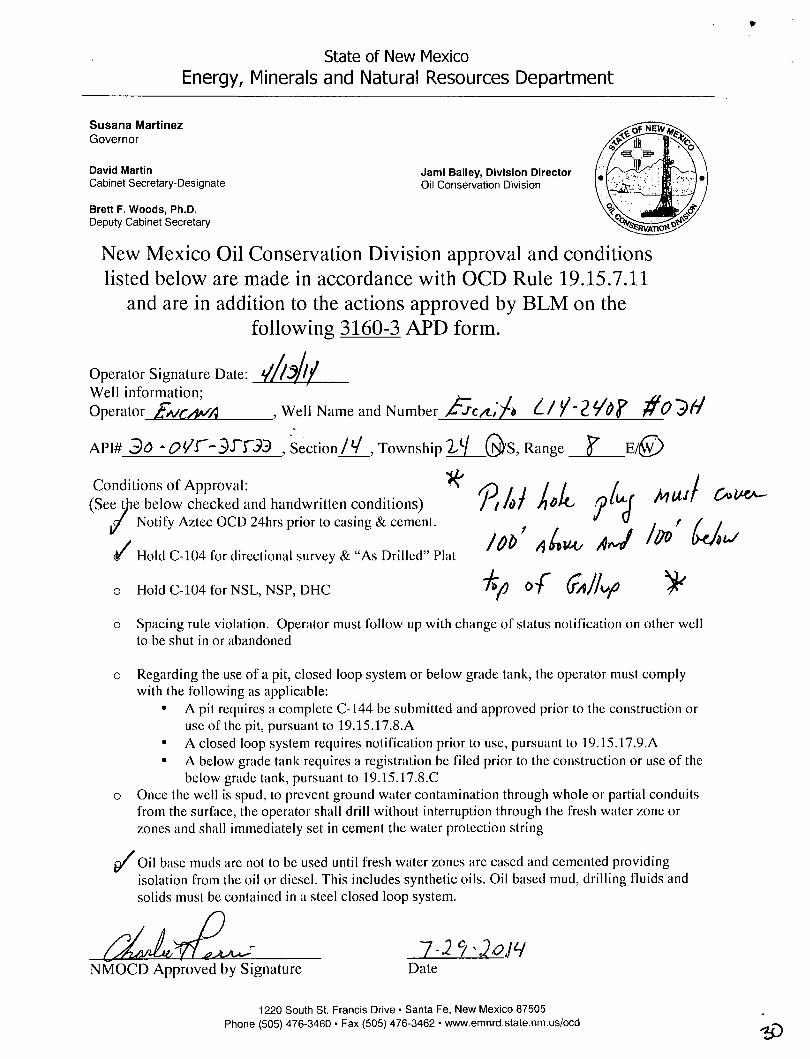
LOC: SE /4 SE/4 15 24N 8W 430 F S L 330
County: San Juan
WELL: Escrito L14-2408 03H
Encana Natural Gas
WELL SUMMARY
E N G : S Kuykendall 4 / 3 / 1 4
RIG: Aztec 950
G L E : 6896
R K B E : 6912
MWD
L.WD
OPEN HOLE
LOGGING
H O L E
SIZE
CASING
S P E C S
MW
MUD T Y P E
DEVIATION
INFORMATION
Multi-Well pad
-take survey
every stand
and run anti-
collision
report prior to
spud Nacimiento
9 5/8" Csg
Survey Every 6O'-120', updating
anticollision report after
surveys. Stop operations
and contact
dr i l l ing engineer if separat ion
factor approaches
1.5
Surveys every
30' through
the curve
Ojo Alamo S s ,
Kirtland Shale
Fruitland Coal
Pictured Cliffs S s .
Lewis Shale
Cliffhouse Ss.
Menefee Fn.
Point Lookout S s .
Mancos Shale
1,339
1,548
1,707
2.057
2,166
2,922
3.629
4,374
4,592
Mud logger
onsite
Gallup Fn,
7" Csg
5,432
5.681
Surveys every
s tand to TD
unless
d i rected
otherwise by
Geologist
MWD
Gamma
Directional
Horizontal Target
Base Gallup
Pilot Hole TD
5,717
5,683
5,767
6,000
20" 94#
100sx Type I Neat 16.0ppg cmt Fresh wtr
8.3-9.2
9 5/8" 36ppf J55 S T C
T O C Sur face - 201 sks o i T y p e III
Cemen t
7" 2 6 p p f J 5 5 L T C
T O C @ sur face
3 0 % O H excess : 714 sksTota l .
S tage 1 Lead : 397 sks P r e m i u m Li te F M
+ 3 % CaCI2 + 0.25/sk Cel lo F lake +
5#/5k LCM-1 + 8 % Bentoni te + 0 .4% FL-
52A + 0 .4% Sod ium Metas i l i ca te . M i x e d
at 12.1 ppg . Y ie ld 2 .13 cuf t /sk.
S tage 1 Ta i l : 316 sks Type III C e m e n t +
1 % CaCI2 + 0.25#/sk Cel lo F lake +
0 .2% FL-52A, M ixed at 14.6 ppg . Y ie ld
1.38 cuf t /sk.
S tage 2 : 1 6 8 sks P r e m i u m Lite F M +
3% CaCI2 + 0.25/sk Cel lo F lake + 5#/sk
LCM-1 + 8% Benton i te + 0 .4% FL-52A
+ 0 .4% Sod ium Metas i l icate. M i x e d at
12.1 ppg. Y ie ld 2.13 cuf t /sk.
200' overlap at liner top Horizontal Inclination
Horizontal TVD
4548' Driiled Lateral
Horz Inc/TVD /90.4
TD = 10601.5 MD
41/2"11 .6ppfSB80 L T C
lunning external swellable csg packers for
isolation of prod string
Plan on setting top packer within 100' of
intermediate casing shoe
Switch to OBM
1) Drill with 30" bit to 60", set 20" 94# conductor pipe
2) Drill surface to 500', R&C 9 5/8" casing
3) N/U BOP and surface equipment
4) Drill to Pilot Hole TD, 8 3/4 inch hole size
5) PU directional tools and drill from KOP of 5300', at 10deg/100' build rate with 8 3/4 inch holesize
6) Drill to csg point of 6053' MD
7) R&C 7" csg, circ cmt to surface, switch to OBM
8) Land at 90 deg, drill lateral to 10602' run 4 1/2 inch liner with external swellable csg packers

Boomerang Tube LLC
CASING (OR) TUBING DESCRIPTION AND PERFORMANCE PROPERTIES
Pipe Outside Diameter (ins) 4.500 Pipe Wall Thickness (ins) 0.250 Nominal Weight Per Foot (lbs) 11.60
Thread Name Long Thread CSG Grade Name SB-80
Pipe Minimum Yield (psi) 80,000 Pipe Minimum Ultimate (psi) 90,000
Coupling Minimum Yield (psi) 80,000 Coupling Minimum Ultimate (psi) 100,000
Coupling or Joint Outside Diameter (ins) . 5.000 Drift Diameter (ins) 3.875 Plain End Weight per Foot (lbs) 11.36
Joint Strength (lbs) 201,000 Internal Yield (psi) 7,780 Collapse Rating (psi) 6,350
MAXIMUM DEPTH/LENGTH BASED ON MUD WTS & SAFETY FACTORS
Drilling Mud Weight (ppg) 9.625
Tension Safety Factor 1.80 Maximum Tension Length (ft) 9,630
Internal Yield Safety Factor 1.10 Maximum Depth for Internal Yield (ft) 14,150
Collapse Safety Factor 1.125 Maximum Collapse Depth (ft) 11,290
API RELATED VALUES and INTERMEDIATE CALCULATION RESULTS
Coupling Thread Fracture Strength 464,000 Pipe Thread Fracture Strength (lbs) 201,000
Pipe Body Plain End Yield (lbs) . 267,000 Round Thread Pull-Out (lbs) 219,000
Minimum Make-up Torque (ft-lbs) 1,640 Nominal Make-up Torque (ft-lbs) 2,190 Maximum Make-up Torque (ft-lbs) 2,740
Coupling Internal Yield (psi) 10,660 Pipe Body Internal Yield (psi) 7,780 Leak @ E1 or E7 plane (psi) 17,920
Pipe Hydrostatic Test Pressure @ 80 % SMYS 7,100
to

natural gas
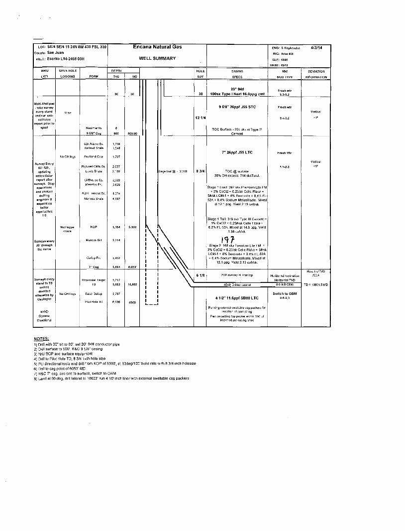
Project: San Juan County, NM Site: S14-T24N-R8W Well: Escrito L14-2408 03H
Wellbore: HZ Design: Plan #1
CATHEDRAL
-1000-
-500-
SECTION DETAILS
Sec MD Inc Azi TVD +N/-S +E/-W Dleg TFace VSect 1 0.0 0.00 0.00 0.0 0.0 0.0 0.00 0.00 0.0 2 3400.0 0.00 0.00 3400.0 0.0 0.0 0.00 0.00 0.0 3 4316.6 27.50 181.57 4281.9 -215.7 -5.9 3.00 181.57 2.3 4 5360.8 27.50 181.57 5208.0 -697.6 -19.1 0.00 0.00 7.4 5 6261.5 90.40 270.96 5712.9 -952.8 -600.0 10.00 89.28 583.9 6 10601.5 90.40 270.96 5682.6 -879.8 -4939.2 0.00 0.00 4923.8
Target
Escrito L14-2408 03H PBHL
X.
5 0 0 - i'ik
1000-
1500 —
Ojo AJamo Ss. •
• : | ' r
Kirtland Shale ;
Fruitland Coal
2000-Pictured Cliffs Ss.
Lewis Shale— —
C
£ o o o
2500-
JZ Q . 3000 -<D
Q
Cliffhouse Ss; .-
| 350°-4 0 0 0 -
Menefee Frir-, —
Point Lookout Ss.
4500-Mancos Shale -
5000-
— KOP @ 3400'
-EOB; lnc=27.50
3500—
3000-
2500-
2000-
o o CM
1500-
1000-
^ 500—
o 00
-500 -
-1000-
-1500-
-2000-
TARGET LINE
5717' TVD @ 0' VS; 90.4°
M Azimuths to True North Magnetic North; 9.46°
Magnetic Field Strength: 50226.1snT
Dip Angle; 63.05° Date: 3/18/2014
Model: IGRF2010
Surface Hole Location Escrito L14-2408 03H
Lat : 36.310648 Long : -107.660466
l l l l l l l l l
-3500 -3000 -2500 -2000 -1500
West(-)/East(+) (1200 ft/in)
5500-
Mancos Silt
Gallup Frtr- — —
-Start build/turn @ 5360' M p - -
7" ICF3^ "
Horizontal Target
Base Gallup'
6000-
6500-
7000-
7500-
_LP@5712'TVD:90.£_
Pilot Hole TD @ 6.000' TVD .
CASING DETAILS
TVD MD 500.0 500.0 5681.2 6053.4
Name 9 5/8"
7" ICP
DESIGN TARGET DETAILS
Name Escrito L14-2408 03H PBHL
+N/-S -879.8
+E/-W Northing Easting Latitude -4939.2 1931536.63 2769090.27 36.308230
Longitude -107.677230
Plan #1 Escrito L14-2408 03H
WELL @ 6912.0ft (Original Well Elev) Ground Elevation @ 6896.0 North American Datum 1983
Well Escrito L14-2408 03H, True North
FORMATION TOP DETAILS
TVDPath MDPath Formation 1339.0 1339.0 Ojo Alamo Ss. 1548.0 1548.0 Kirtland Shale 1707.0 1707.0 Fruitland Coal 2057.0 2057.0 Pictured Cliffs Ss. 2166.0 2166.0 Lewis Shale 2922.0 2922.0 Cliffhouse Ss. 3629.0 3629.6 Menefee Fn. 4374.0 4420.5 Point Lookout Ss. 4592.0 4666.3 Mancos Shale 5213.9 5367.5 Mancos Silt 5431.5 5622.1 Gallup Fn.
11111111111111111111111
2000 2500 3000
T 11111 j 11111
3500
1111111111111111
4000 4500
11111111
5000
I 11 111 I I I I I I I 111 I 1111 I I I
5500 6000
I I 111 I I
6500 11 111 11111111111 I I I I I 111111111 11111 I I I
-500 0 500 1000
nT I I I I
1500
Vertical Section at 270.96° (1000 ft/in)
ENCANA„ Planning Report
Database: ' USA EDM 5000 Multi Users DB : Local Co-ordinate Reference: j Well Escrito L14-2408 03H \
Company: EnCana Oil & Gas (USA) Inc TVD Reference: ' WELL @ 6912.0ft (Original Well Elev) Project: San Juan County, NM i MD Reference: , WELL @ 6912.0ft (Original Well Elev)
Site: S14-T24N-R8W • North Reference: ] True
Well: Escrito L14-2408 03H ; Survey Calculation Method: i Minimum Curvature
Wellbore: ; HZ | ! Design: '• Plan #1
_ „ 1 i I
Project ' San Juan County, NM I I I Map System: US State Plane 1983 System Datum: Mean Sea Level
Geo Datum: North American Datum 1983
Map Zone: New Mexico Western Zone
Site S14-T24N-R8W __ ' .. 11_V. ' ]
Site Position: Northing: 1,932,462.42 ft Latitude: 36.310750
From: Lat/Long Easting: 2,774,050.25ft Longitude: -107.660390
Position Uncertainty: 0.0 ft Slot Radius: 13.200 in Grid Convergence: 0.10 0
Well Escrito L I 4-2408 ; 03H" "_ . . . . .
Well Position +N/-S 0.0 ft Northing: 1,932,425.25 ft Latitude: 36.310648
+E/-W 0.0 ft Easting: 2,774,027.93 ft Longitude: -107.660466
Position Uncertainty 0.0 ft Wellhead Elevation: ft Ground Level: 6,896.0 fl
Wellbore HZ ~ -
Magnetics Model Name Sample Date Declination Dip Angle Field Strength
n n (nT)
IGRF2010 3/18/2014 9.46 63.05 50,226
Design ' Plan #1
Audit Notes:
Version: Phase: PLAN Tie On Depth: 0.0
Vertical Section: Depth From (TVD)
(ft)
+N/-S
(ft)
~ +E/-W
(ft)
Direction
(°) " " o . o CO 0.0 270.96
Plan Sections .. . . '. '
Measured Vertical Dogleg Build Turn Depth Incl inat ion Azimuth Depth +N/-S +E/-W Rate Rate Rate TFO
(ft) O (°) (ft) (ft) (ft) ("/100ft) (•7100ft) (°/100ft) (°) Target
0.0 0.00 0.00 0.0 0.0 0.0 0.00 0.00 0.00 0.00
3,400.0 0.00 0.00 3,400.0 0.0 0.0 0.00 0.00 0.00 0.00
4,316.6 27.50 181.57 4,281.9 -215.7 -5.9 3.00 3.00 0.00 181.57
5,360.8 27.50 181.57 5,208.0 -697.6 -19.1 0.00 0.00 0.00 0.00
6,261.5 90.40 270.96 5,712.9 -952.8 -600.0 10.00 6.98 9.92 89.28
10,601.5 90.40 270.96 5,682.6 -879.8 -4,939.2 0.00 0.00 0.00 0.00 Escrito L14-2408 03H
3/31/2014 1:52:35PM Page 1 COMPASS 5000.1 Build 62

Planning Report
Database: Company: Project: Site: Well: Wellbore: Design:
; USA EDM 5000 Multi Users DB EnCana Oil & Gas (USA) Inc San Juan County, NM
i S14-T24N-R8W Escrito L14-2408 03H
, HZ Plan #1
Local Co-ordinate Reference: TVD Reference: MD Reference: North Reference: Survey Calculation Method:
, Well Escrito L14-2408 03H
WELL @ 6912.0ft (Original Well Elev) ' WELL @ 6912.0ft (Original Well Elev)
True . Minimum Curvature
Planned Survey
Measured Vertical Vertical Dogleg Build Comments / Depth Inclination Azimuth Depth +N/-S +E/-W Section Rate Rate Formations
(ft) n C) (ft) (ft) («) (ft) (YlOOft) (°/100ft)
0.0 0.00 0.00 0.0 0.0 0.0 0.0 0.00 0.00 100.0 0.00 0.00 100.0 0.0 0.0 0.0 0.00 0.00 200.0 0.00 0.00 200.0 0.0 0.0 0.0 0.00 0.00 300.0 0.00 0.00 300.0 0.0 0.0 0.0 0.00 0.00 400.0 0.00 0.00 400.0 0.0 0.0 0.0 0.00 0.00
500.0 0.00 0.00 500.0 0.0 0.0 0.0 0.00 0.00 9 5/8" 600.0 0.00 0.00 600.0 0.0 0.0 0.0 0.00 0.00 700.0 0.00 0.00 700.0 0.0 0.0 0.0 0.00 0.00 800.0 0.00 0.00 800.0 0.0 0.0 0.0 0.00 0.00 900.0 0.00 0.00 900.0 0.0 0.0 0.0 0.00 0.00
1,000.0 0.00 0.00 1,000.0 0.0 0.0 0.0 0.00 0.00 1,100.0 0.00 0.00 1,100.0 0.0 0.0 0.0 0.00 0.00 1,200.0 0.00 0.00 1,200.0 0.0 0.0 0.0 0.00 0.00 1,300.0 0.00 0.00 1,300.0 0.0 0.0 0.0 0.00 0.00 1,339.0 0.00 0.00 1,339.0 0.0 0.0 0.0 0.00 0.00 Ojo Alamo Ss.
1,400.0 0.00 0.00 1.400.0 0.0 0.0 0.0 0.00 0.00 1,500.0 0.00 0.00 1,500.0 0.0 0.0 0.0 0.00 0.00 1,548.0 0.00 0.00 1,548.0 0.0 0.0 0.0 0.00 0.00 Kirtland Shale 1,600.0 0.00 0.00 1,600.0 0.0 0.0 0.0 0.00 0.00 1,700.0 0.00 0.00 1.700.0 0.0 0.0 0.0 0.00 0.00
1,707.0 0.00 0.00 1,707.0 0.0 0.0 0.0 0.00 0.00 Fruitland Coal 1,800.0 0.00 0.00 1,800.0 0.0 0.0 0.0 0.00 0.00 1,900.0 0.00 0.00 1,900.0 0.0 0.0 0.0 0.00 0.00 2,000.0 0.00 0.00 2,000.0 0.0 0.0 0.0 0.00 0.00 2,057.0 0.00 0.00 2,057.0 0.0 0.0 0.0 0.00 0.00 Pictured Cliffs Ss.
2,100.0 0.00 0.00 2,100.0 0.0 0.0 0.0 0.00 0.00 2,166.0 0.00 0.00 2,166.0 0.0 0.0 0.0 0.00 0.00 Lewis Shale 2,200.0 0.00 0.00 2,200.0 0.0 0.0 0.0 0.00 0.00 2,300.0 0.00 0.00 2,300.0 0.0 0.0 0.0 0.00 0.00 2,400.0 0.00 0.00 2,400.0 0.0 0.0 0.0 0.00 0.00
2,500.0 0.00 0.00 2,500.0 0.0 0.0 0.0 0.00 0.00 2,600.0 0.00 0.00 2,600.0 0.0 0.0 0.0 0.00 0.00 2,700.0 0.00 0.00 2,700.0 0.0 0.0 0.0 0.00 0.00 2,800.0 0.00 0.00 2,800.0 0.0 0.0 0.0 0.00 0.00 2,900.0 0.00 0.00 2,900.0 0.0 0.0 0.0 0.00 0.00
2,922.0 0.00 0.00 2,922.0 0.0 0.0 0.0 0.00 0.00 Cliffhouse Ss. 3,000.0 0.00 0.00 3,000.0 0.0 0.0 0.0 0.00 0.00 3,100.0 0.00 0.00 3,100.0 0.0 0.0 0.0 0.00 0.00 3,200.0 0.00 0.00 3,200.0 0.0 0.0 0.0 0.00 0.00 3,300.0 0.00 0.00 3,300.0 0.0 0.0 0.0 0.00 0.00
3,400.0 0.00 0.00 3,400.0 0.0 0.0 0.0 0.00 0.00 KOP @ 3400' 3,500.0 3.00 181.57 3,500.0 -2.6 -0.1 0.0 3.00 3.00 3,600.0 6.00 181.57 3,599.6 -10.5 -0.3 0.1 3.00 3.00 3,629.6 6.89 181.57 3,629.0 -13.8 -0.4 0.1 3.00 3.00 Menefee Fn. 3,700.0 9.00 181.57 3,698.8 -23.5 -0.6 0.2 3.00 3.00
3,800.0 12.00 181.57 3,797.1 -41.7 -1.1 0.4 3.00 3.00 3,900.0 15.00 181.57 3,894.3 -65.1 -1.8 0.7 3.00 3.00 4,000.0 18.00 181.57 3,990.2 -93.4 -2.6 1.0 3.00 3.00 4,100.0 21.00 181.57 4,084.4 -126.8 -3.5 1.3 3.00 3.00 4,200.0 24.00 181.57 4,176.8 -165.1 -4.5 1.7 3.00 3.00
4,300.0 27.00 181.57 4,267.1 -208.1 -5.7 2.2 3.00 3.00 4,316.6 27.50 181.57 4,281.8 -215.7 -5.9 2.3 3.00 3.00 EOB; lnc=27.50°
3/31/2014 1:52:35PM Page 2 COMPASS 5000.1 Build 62

Planning Report
j Database: USA EDM 5000 Multi Users DB Local Co-ordinate Reference: Well Escrito L14-2408 03H ! Company: EnCana Oil & Gas (USA) Inc TVD Reference: WELL @ 6912.0ft (Original Well Elev) Project: San Juan County, NM MD Reference: WELL @ 6912.0ft (Original Well Elev)
j Site: S14-T24N-R8W ' North Reference: True | Well: Escrito L14-2408 03H Survey Calculation Method: Minimum Curvature
j Wellbore: HZ j Design: Plan #1
Planned Survey
Measured Vertical Vertical Dogleg Build Depth Inclination Azimuth Depth +N/-S +E/-W Section Rate Rate
(ft) n n (ft) («) (ft) (ft) (7100ft) (7100ft)
4,400.0 27.50 181.57 4,355.8 -254.2 -7.0 2.7 0.00 0.00 4,420.5 27.50 181.57 4,374.0 -263.6 -7.2 2.8 0.00 0.00 4,500.0 27.50 181.57 4,444.5 -300.3 -8.2 3.2 0.00 0.00
4,600.0 27.50 181.57 4,533.2 -346.5 -9.5 3.7 0.00 0.00 4,666.3 27.50 181.57 4,592.0 -377.1 -10.3 4.0 0.00 0.00 4,700.0 27.50 181.57 4,621.9 -392.6 -10.7 4.2 0.00 0.00 4,800.0 27.50 181.57 4,710.6 -438.8 -12.0 4.7 0.00 0.00 4,900.0 27.50 181.57 4,799.3 -485.0 -13.3 5.1 0.00 0.00
5,000.0 27.50 181.57 4,888.0 -531.1 -14.5 5.6 0.00 0.00 5,100.0 27.50 181.57 4,976.7 -577.3 -15.8 6.1 0.00 0.00 5,200.0 27.50 181.57 5,065.4 -623.4 -17.1 6.6 0.00 0.00 5,300.0 27.50 181.57 5,154.1 -669.6 -18.3 7.1 0.00 0.00 5,360.8 27.50 181.57 5,208.0 -697.6 -19.1 7.4 0.00 0.00
5,367.5 27.52 183.02 5,213.9 -700.7 -19.2 7.5 10.07 0.24 5,400.0 27.81 190.00 5,242.8 -715.7 -20.9 8.9 10.00 0.89 5,450.0 28.91 200.28 5,286.8 -738.5 -27.1 14.8 10.00 2.21 5,500.0 30.73 209.66 5,330.2 -761.0 -37.7 24.9 10.00 3.65 5,550.0 33.16 217.93 5,372.6 -782.9 -52.4 39.3 10.00 4.84
5,600.0 36.06 225.12 5,413.8 -804.1 -71.2 57.8 10.00 5.80 5,622.1 37.46 227.97 5,431.5 -813.2 -80.8 67.2 10.00 6.36 5,650.0 39.33 231.31 5,453.4 -824.4 -94.0 80.2 10.00 6.68 5,700.0 42.88 236.66 5,491.1 -843.6 -120.6 106.5 10.00 7.11 5,750.0 46.65 241.33 5.526.6 -861.7 -150.8 136.4 10.00 7.54
5,800.0 50.59 245.44 5,559.6 -878.5 -184.4 169.6 10.00 7.88 5,850.0 54.66 249.10 5,590.0 -893.8 -221.0 206.0 10.00 8.14 5,900.0 58.83 252.40 5,617.4 -907.6 -260.5 245.2 10.00 8.34 5,950.0 63.07 255.42 5,641.7 -919.6 -302.5 287.0 10.00 8.49 6,000.0 67.38 258.23 5,662.6 -930.0 -346.6 331.0 10.00 8.61
6,050.0 71.73 260.86 5,680.1 -938.4 -392.7 376.9 10.00 8.70 6,053.4 72.02 261.03 5,681.2 -939.0 -395.9 380.1 10.00 8.74 6,100.0 76.11 263.36 5.693.9 -945.0 -440.3 424.4 10.00 8.77 6,150.0 80.52 265.77 5,704.1 -949.7 -489.0 473.0 10.00 8.82 6,200.0 84.95 268.12 5,710.4 -952.3 -538.5 522.5 10.00 8.85
6,250.0 89.38 270.43 5,712.9 -952.9 -588.4 572.4 10.00 8.87 6,261.5 90.40 270.96 5,712.9 -952.8 -599.9 583.9 10.00 8.87 6,300.0 90.40 270.96 5,712,6 -952.1 -638.4 622.4 0.00 0.00 6,400.0 90.40 270.96 5,711.9 -950.5 -738.4 722.4 0.00 0.00 6,500.0 90.40 270.96 5,711.2 -948.8 -838.4 822.4 0.00 0.00
6,600.0 90.40 270.96 5,710.5 -947.1 -938.4 922.4 0.00 0.00 6,700.0 90.40 270.96 5,709.8 -945.4 -1,038.4 1,022.4 0.00 0.00 6,800.0 90.40 270.96 5,709.1 -943.7 -1,138.4 1,122.4 0.00 0.00 6,900.0 90.40 270.96 5.708.4 -942.0 -1,238.3 1,222.4 0.00 0.00 7,000.0 90.40 270.96 5,707.7 -940.4 -1,338.3 1,322.4 0.00 0.00
7,100.0 90.40 270.96 5,707.0 -938.7 -1,438.3 1,422.4 0.00 0.00 7,200.0 90.40 270.96 5,706.3 -937.0 -1,538.3 1,522.4 0.00 0.00 7,300.0 90.40 270.96 5,705.6 -935.3 -1,638.3 1,622.4 0.00 0.00 7,400.0 90.40 270.96 5,704.9 -933.6 -1,738.3 1,722.4 0.00 0.00 7,500.0 90.40 270.96 5,704.2 -932.0 -1,838.2 1,822.4 0.00 0.00
7,600.0 90.40 270.96 5,703.5 -930.3 -1,938.2 1.922.4 0.00 0.00 7,700.0 90.40 270.96 5,702.9 -928.6 -2,038.2 2,022.4 0.00 0.00 7,800.0 90.40 270.96 5,702.2 -926.9 -2,138.2 2,122.4 0.00 0.00 7,900.0 90.40 270.96 5,701.5 -925.2 -2,238.2 2.222.4 0.00 0.00
Comments / Formations
Mancos Shale
Start build/turn @ 5360' MD
Mancos Silt
Gallup Fn.
7" ICP
LP @ 5712' TVD; 90.4°
3/31/2014 1:52:35PM Page 3 COMPASS 5000.1 Build 62

Planning Report
| Database: Company: Project: Site: Well: Wellbore: Design:
USA EDM 5000 Multi Users DB
EnCana Oil & Gas (USA) Inc , San Juan County, NM S14-T24N-R8W
; Escrito L14-2408 03H
HZ Plan #1
Local Co-ordinate Reference: TVD Reference:
', KID Reference: North Reference: Survey Calculation Method:
• Well Escrito L14-2408 03H j WELL @ 6912.0ft (Original Well Elev) ; WELL @ 6912.0ft (Original Well Elev) i True j Minimum Curvature
Planned Survey
Measured Vertical Vertical Dogleg Build Comments / D e P t n Inclination Azimuth Depth +N/-S +E/-W Section Rate Rate Formations
(") n n (ft) (ft) (ft) (ft) (7100ft) (7100ft)
8,000.0 90.40 270.96 5,700.8 -923.5 -2,338.2 2,322.4 0.00 0.00
8,100.0 90.40 270.96 5,700.1 -921.9 -2,438.1 2,422.3 0.00 0.00 8,200.0 90.40 270.96 5,699.4 -920.2 -2,538.1 2,522.3 0.00 0.00 8,300.0 90.40 270.96 5.698.7 -918.5 -2,638.1 2,622.3 0.00 0.00 8,400.0 90.40 270.96 5,698.0 -916.8 -2,738.1 2,722.3 0.00 0.00 8,500.0 90.40 270.96 5,697.3 -915.1 -2,838.1 2,822.3 0.00 0.00
8,600.0 90.40 270.96 5,696.6 -913.5 -2,938.1 2,922.3 0.00 0.00 8,700.0 90.40 270.96 5,695.9 -911.8 -3,038.0 .3,022.3 0.00 0.00 8,800.0 90.40 270.96 5,695.2 -910.1 -3,138.0 3,122.3 0.00 0.00 8,900.0 90.40 270.96 5,694.5 -908.4 -3,238.0 3,222.3 0.00 0.00 9,000.0 90.40 270.96 5,693.8 -906.7 -3,338.0 3,322.3 0.00 0.00
9,100.0 90.40 270.96 5,693.1 -905.0 -3,438.0 3,422.3 0.00 0.00 9,200.0 90.40 270.96 5,692.4 -903.4 -3,538.0 3,522.3 0.00 0.00 9,300.0 90.40 270.96 5,691.7 -901.7 • -3,637.9 3,622.3 0.00 0.00 9,400.0 90.40 270.96 5,691.0 -900.0 -3,737.9 3,722.3 0.00 0.00 9,500.0 90.40 270.96 5,690.3 -898.3 -3,837.9 3,822.3 0.00 0.00
9,600.0 90.40 270.96 5,689.6 -896.6 -3,937.9 3,922.3 0.00 0.00 9,700.0 90.40 270.96 5,688.9 -895.0 -4,037.9 4,022.3 0.00 0.00 9,800.0 90.40 270.96 5,688.2 -893.3 -4,137.9 4,122.3 0.00 0.00 9,900.0 90.40 270.96 5,687.5 -891.6 -4,237.8 4,222.3 0.00 0.00
10,000.0 90.40 270.96 5,686.8 -889.9 -4,337.8 4,322.3 0.00 0.00
10,100.0 90.40 270.96 5,686.1 -888.2 -4,437.8 4,422.3 0.00 0.00 10,200.0 90.40 270.96 5,685.4 -886.5 -4,537.8 4,522.3 0.00 0.00 10,300.0 90.40 270.96 5,684.7 -884.9 -4,637.8 4,622.3 0.00 0.00 10,400.0 90.40 270.96 5,684.0 -883.2 -4,737.8 4,722.3 0.00 0.00 10,500.0 90.40 270.96 5,683.3 -881.5 -4,837.7 4,822.3 0.00 0.00
10,601.5 90.40 270.96 5,682.6 -879.8 -4,939.2 4,923.8 0.00 0.00 TDat 10601.5
Targets .. . . _ . ... ... — -
Target Name - hit/miss target Dip Angle Dip Dir. TVD +N/-S +E/-W Northing Easting - Shape n n (ft) (ft) (ft) (ft) (ft) Latitude Longitude
Escrito L14-2407 03H Pi 0.00 0.00 5,714.5 -956.7 -369.5 1.931,467.92 2,773,660.17 36.308020 -107.661720 - plan misses target center by 44.7ft at 6043.7ft MD (5678.1 TVD, -937.5 N, 386.8 E) - Point
Escrito L14-2408 03H PI 0.00 0.00 5,682.6 -879.8 -4,939.2 1,931,536.63 2,769,090.27 36.308230 -107.677230 - plan hits target center - Point
Casing Points
Measured Vertical Casing Hole Depth Depth Diameter Diameter
(ft) (ft) Name (in) (in)
500.0 500.0 9 5/8" 0.000 0.000
6,053.4 5,681.2 7" ICP 0.000 0.000
3/31/2014 1:52:35PM Page 4 COMPASS 5000.1 Build 62
Planning Report
Database:
Company: Project: Site: Well:
Wellbore: Design:
• USA EDM 5000 Multi Users DB i
; EnCana Oil & Gas (USA) Inc ' San Juan County, NM | S14-T24N-R8W i Escrito L14-2408 03H ' HZ i Plan #1
I
Local Co-ordinate Reference:
TVD Reference: MD Reference: North Reference: Survey Calculation Method:
! Well Escrito L14-2408 03H ! WELL @ 6912.0ft (Original Well Elev) | WELL @ 6912.0ft (Original Well Elev) | True
I Minimum Curvature
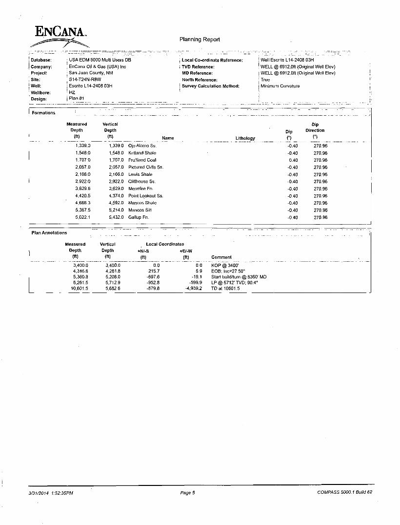
_ — - , _ „ _ - _ -Formations > .. - -> Measured Vertical Dip
Depth Depth Dip Direction
(ft) (ft) Name Lithology n n 1,339.0 1,339.0 Ojo Alamo Ss. -0.40 270.96
1.548.0 1,548.0 Kirtland Shale -0.40 270.96
1,707.0 1,707.0 Fruitland Coal -0.40 270.96
2,057.0 2,057.0 Pictured Cliffs Ss. -0.40 270.96
2,166.0 2,166.0 Lewis Shale -0.40 270.96
2,922.0 2,922.0 Cliffhouse Ss. -0.40 270.96
3,629.6 3,629.0 Menefee Fn. -0.40 270.96
4,420.5 4,374.0 Point Lookout Ss. -0.40 270.96
4,666.3 4,592.0 Mancos Shale -0.40 270.96
5,367.5 5,214.0 Mancos Silt -0.40 270.96
5,622.1 5,432.0 Gallup Fn. -0.40 270.96
Plan Annotations
leasured Vertical Local Coordinates Depth Depth +N(-S +B-W
(ft) (ft) (ft) (ft) Comment
3,400.0 3,400.0 0.0 0.0 KOP @ 3400' 4,316.6 4,281.8 -215.7 -5.9 EOB; lnc=27.50° 5,360.8 5,208.0 -697.6 -19.1 Start build/turn @ 5360' MD 6,261.5 5,712.9 -952.8 -599.9 LP @ 5712' TVD; 90.4°
10,601.5 5,682.6 -879.8 -4,939.2 TD at 10601.5
3/31/2014 1:52:35PM Page 5 COMPASS 5000.1 Build 62
ENCANA
EnCana Oil & Gas (USA) Inc San Juan County, NM S14-T24N-R8W Escrito L14-2408 03H HZ Plan #1
Anticollision Report
31 March, 2014
if ii

Anticollision Report
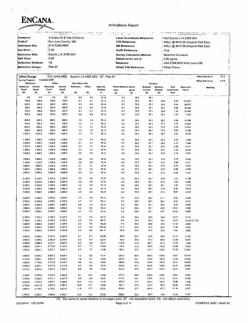
, , J^LZSZ—. zr*jrt~._z^_z: . ' . Jl- • • ; -.— _ . -- _ . Company: EnCana Oil & Gas (USA) Inc Local Co-ordinate Reference: ' Well Escrito L14-2408 03H Project: :San Juan County, NM : TVD Reference: i WELL @ 6912.0ft (Original Well Elev) ; Reference Site: S14-T24N-R8W MD Reference: ' WELL @ 6912.0ft (Original Well Elev)
Site Error: ; 0.0ft North Reference: ! True I I
Reference Well: Escrito L14-2408 03H Survey Calculation Method: Minimum Curvature I
Well Error: 0.0ft , Output errors are at 2.00 sigma I Reference Wellbore :HZ Database: : USA EDM 5000 Multi Users DB j Reference Design: I Plan #1 , Offset TVD Reference: • Offset Datum
Reference ; Plan #7 ~" " f . ~
Filter type: NO GLOBAL FILTER: Using user defined selection & filtering criteria Interpolation Method: Stations Error Model: Systematic Ellipse Depth Range: Unlimited Scan Method: Closest Approach 3D Results Limited by: Maximum center-center distance of 1,550.0ft Error Surface: Elliptical Conic Warning Levels Evaluated at: 2.00 Sigma
Survey Tool Program i
Date 3/31/2014
i | From
To
(ft) (ft) Survey (Wellbore) Tool Name Description
0.0 10,601.5 Plan#1 (HZ) Geolink MWD Geolink MWD
Summary . . .
Reference Offset Distance Measured Measured Between Between Separation Warning
Site Name Depth Depth Centres Ellipses Factor Offset Well - Wellbore - Design (ft) (ft) (ft) (ft)
S14-T24N-R8W
Escrito L14-2408 01H - HZ - Plan #1 3.400.0 3,400.0 42.4 30.6 3.592 CC, ES, SF Escrito L14-2408 02H - HZ - Plan #1 3,158.2 3,158.3 29.4 18.4 2.678 CC, ES Escrito L14-2408 02H - HZ - Plan #1 5,450.0 5,409.2 68.6 40.3 2.424 SF Escrito L14-2408 04H - HZ - Plan #1 3,400.0 3,400.0 30.1 18.3 2.551 CC, ES. SF
S16-T24N-R8W
Escrito D16A-2408 01H - Hz - Plan #2 10,601.8 11,816.8 669.2 454.7 3.120 CC, ES, SF
3/31/2014 1:53:37PM
CC - Min centre to center distance or covergent point, SF - min separation factor, ES - min ellipse separation Page 2 of 11 COMPASS 5000.1 Build 62

ENCANA. Anticollision Report
Company: Project: Reference Site: Site Error: Reference Well: Well Error: Reference Wellbore Reference Design:
; EnCana Oil & Gas (USA) Inc San Juan County, NM S14-T24N-R8W
,0.0ft
Escrito L14-2408 03H : 0.0ft
;HZ
iPlan#1
Local Co-ordinate Reference: , TVD Reference: ; MD Reference: | North Reference: ! Survey Calculation Method: I Output errors are at ! Database:
: Offset TVD Reference:
Well Escrito L14-2408 03H WELL @ 6912.0ft (Original Well Elev) WELL @ 6912.0ft (Original Well Elev) True
Minimum Curvature 2.00 sigma
USA EDM 5000 Multi Users DB
Offset Datum
1
... ^ - - — ... - - - . ! Offset Design , S14-T24N-R8W- Escrito L14-2408 01H - HZ - Plan #1 \ Offset Site Error: 0.0 ft
. Survey Program: 0-Geolink MWD
Reference Offset Semi Major Axis Distance Offset Well Error: 0.0 ft
Measured
Depth
(ft)
Vertical
Depth
(ft]
Measured
Depth
(ft)
Vertical
Depth
(ft)
Reference
(ft)
Offset
(ft)
Highside
Toolface
C)
Offset Wellbore Centre
+N/-S +E/-W
(ft) (ft)
Between
Centres
(ft)
Between
Ellipsos
(ft)
Total Uncertainty
Axis
Separation Warning Factor
0.0 0.0 0.0 0.0 0.0 0.0 32.79 35.7 23.0 42.4
100.0 100.0 100.0 100.0 oil 0.1 32.79 35.7 23.0 42.4 42.1 0.29 144.726 200.0 200.0 200.0 200.0 0.3 0.3 32.79 35.7 23.0 42.4 41.8 0.64 66.071
300.0 300.0 300.0 300.0 0.5 0.5 32.79 35.7 23.0 42.4 41.4 0,99 42.806
400.0 400.0 400.0 400.0 0.7 0.7 32.79 35.7 23.0 42.4 41.1 1.34 31.659
500.0 500.0 500.0 500.0 0.8 0.8 32.79 35.7 23.0 42.4 40.7 1.69 25.118
600.0 600.0 600.0 600.0 1.0 1.0 32.79 35.7 23.0 42.4 40.4 2.04 20.817
700.0 700.0 700.0 700.0 1.2 1.2 32.79 35.7 23.0 42.4 40.0 2.39 17.773
800.0 800.0 800.0 800.0 1.4 1.4 32.79 35.7 23.0 42.4 39.7 2.74 15.506
900.0 900.0 900.0 900.0 1.5 1.5 32.79 35.7 23.0 42.4 39.4 3.09 13.752
1,000.0 1.000.0 1.000.0 1.000.0 1.7 1.7 32.79 35.7 23.0 42.4 39.0 3.43 12,355
1.100.0 1.100.0 1,100.0 1.100.0 1.9 1.9 3279 35.7 23.0 42.4 38.7 3,78 11.215
1.200.0 1,200.0 1.200.0 1.200.0 2.1 2.1 32.79 35.7 23.0 42.4 38.3 4.13 10.268
1,300.0 1.300.0 1,300.0 1.300.0 2.2 2.2 32.79 35.7 23.0 42.4 38.0 4.48 9.468
1.400.0 1.400.0 1.400.0 1.400.0 2.4 2.4 32.79 35.7 23.0 42.4 37.6 4.83 8.784
1.500.0 1.500.0 1,500.0 1.500,0 2,6 2.6 32.79 35.7 23.0 42.4 37.3 5.18 8.192
1.600.0 1.600.0 1.600.0 1.600.0 2.8 2.8 32.79 35.7 23.0 42.4 36.9 5.53 7.675
1.700.0 1.700.0 1,700.0 1.700.0 2.9 2.9 3279 35.7 23.0 42.4 36.6 5.88 7.219
1.800.0 1,800.0 1,800.0 1.800.0 3.1 3.1 32.79 35.7 23,0 42.4 36,2 6.23 6.814
1.900.0 1.900.0 1,900.0 1.900.0 3.3 3.3 32.79 35.7 23.0 42.4 35.9 6.58 6.453
2.000.0 2,000.0 2.000.0 2.000.0 3.5 3.5 32.79 35.7 23.0 42.4 35.5 6.93 6.128
2.100.0 2.100.0 2.100.0 2,100.0 3.6 3.6 32.79 35.7 23.0 42.4 35.2 7.27 5.833
2,200.0 2.200.0 2.200.0 2.200.0 3,8 3.8 32.79 35.7 23.0 42.4 34.8 7.62 5.566
2.300.0 2,300.0 2.300.0 2,300.0 4.0 4.0 32.79 35.7 23.0 42.4 34.5 7.97 5.323
2,400.0 2.400.0 2.400.0 2.400.0 4.2 4.2 3279 35.7 23,0 42.4 34.1 8.32 5.099
2.500.0 2.500.0 2.500.0 2.500.0 4.3 4.3 32.79 35.7 23.0 42.4 33.8 8.67 4.894
2.600.0 2.600.0 2,600.0 2.600.0 4.5 4.5 32.79 35.7 23.0 42.4 33.4 9.02 4.705
2.700.0 2,700.0 2,700.0 2,700.0 4.7 4.7 32.79 35.7 23.0 42.4 33.1 9.37 4.529
2.800.0 2.800.0 2,800.0 2.800.0 4.9 4.9 32.79 35.7 23.0 42.4 32.7 9.72 4.367
2,900.0 2,900.0 2.900.0 2,900.0 5.0 5.0 32.79 35.7 23.0 42.4 32.4 10.07 4.215
3.000.0 3.000.0 3.000.0 3.000.0 5.2 5.2 32.79 35.7 23.0 42.4 32.0 10.42 4.074
3.100.0 3,100.0 3,100.0 3.100.0 5.4 5.4 32.79 35.7 23.0 42.4 31.7 10.77 3,942
3.200.0 3.200.0 3.200.0 3,200.0 5.6 5.6 32.79 35.7 23.0 42.4 31.3 11.11 3.818
3.300.0 3,300.0 3.300.0 3.300.0 5.7 5.7 32.79 35.7 23.0 42.4 31.0 11.46 3.702
3.400.0 3,400.0 3.400.0 3.400.0 5.9 5.9 32.79 35.7 23,0 42.4 30.6 11.81 3.592 CC, ES. SF
3.500.0 3.500.0 3,500.0 3.500.0 6.1 6.1 -150.48 35.7 23.0 44.7 32.5 12.15 3.678
3.600.0 3,599.6 3,597.2 3.597.2 6.3 6.3 -155.83 38.1 22.9 53.9 41.4 12.47 4.324
3.700.0 3.698.8 3,692.2 3.691.9 6.5 6.4 -162.38 45.3 22.7 73.0 60.3 12.75 5.724
3.800.0 3,797.1 3.783.5 3,782.5 6.7 6.6 -167.50 56.7 22.4 102,2 89.2 13.01 7.859
3,900.0 3,894.3 3.875,9 3.873.9 6.9 6.8 -170.99 70,5 21.9 139.2 125.9 13.23 10.518
4,000.0 3,990.2 3.966,5 3.963.4 7.2 7.0 -173.19 84.1 21.5 181,2 167.7 13.42 13.495
4,100.0 4,084.4 4,054.7 4.050.5 7.6 7.2 -174.66 97,3 21.2 228.0 214.4 13.59 16.779
4.200.0 4.176.8 4,140.3 4.135.2 8.0 7.3 -175.68 110.2 20.8 279.5 265,8 13.72 20.364
4.300.0 4,267.1 4.223.0 4,217.0 8.5 7.5 -176.42 122.6 20.4 335.4 321.6 13.83 24.254
4.316.6 4,281.9 4,236.5 4.230.4 8.6 7.6 -176.52 124.6 20.3 345.2 331.3 13.85 24.931
4.400.0 4.355.8 4,303.9 4,296.9 9.1 7.7 -177.06 134.7 20.0 394.2 380.1 14.10 27.953
4,500.0 4,444.5 4,384.6 4.376.8 9.6 7.9 -177.55 146.8 19.7 453.1 438.7 14.41 31.438
4.600.0 4.533.2 4,465.4 4,456.7 10.3 8.1 -177.93 158.9 19.3 512.0 497.3 14.72 34.777
4,700,0 4.621.9 4,546.2 4.536,5 10.9 8.3 -178,23 171.0 19.0 570.9 555.9 15.03 37,980
4.800.0 4,710.6 4,627.0 4,616.4 11.6 8.5 -178.47 183.2 18.6 629.8 614.5 15.34 41.055
4.900.0 4.799.3 4,707.8 4,696.3 12.3 8.7 -178.67 195.3 18.2 688.7 673.1 15.65 44.010
5.000.0 4,888.0 4.788,5 4.776.1 13.0 8.9 -178.84 207.4 17.9 747.6 731.7 15,96 46.851
3/31/2014 1:53:37PM
CC - Min centre to center distance or covergent point, SF - min separation factor, ES - min ellipse separation
Page 3 of 11 COMPASS 5000.1 Build 62

Anticollision Report
Company: Project: Reference Site: Site Error: Reference Well: Well Error: Reference Wellbore Reference Design:
EnCana Oil & Gas (USA) Inc San Juan County, NM
' S14-T24N-R8W 10.0ft
; Escrito L14-2408 03H i 0.0ft jHZ Plan#1
Local Co-ordinate Reference: TVD Reference: MD Reference: North Reference: Survey Calculation Method:
, Output errors are at Database:
Offset TVD Reference:
Well Escrito L14-2408 03H WELL @ 6912.0ft (Original Well Elev) WELL @ 6912.0ft (Original Well Elev)
True
Minimum Curvature 2.00 sigma USA EDM 5000 Multi Users DB Offset Datum
| Offset Design [^ I?4 t>R8W": j Survey Program: 0-Geolink MWD
I Reference Offset
Escrito L14-2408 01H - HZ - Plan #1
Semi Major Axis Distance
Offset Site Error:
Offset Well Error:
0.0 ft
0.0 ft
j Measured I Depth ! (ft)
Vertical
Depth
(ft)
Measured
Depth
(ft)
Vertical Depth
ro
Reference
l«>
Offset
(fl)
Highside
Toolface
C)
Offset Wellbore Centre
•N/-S •EM/V
(ft) (ft)
Between
Centres
(ft)
Between Ellipses
(n)
Total Uncertainty
Axis
Separation Factor
Warning
5.100.0 4.976.7 4.869.3 4.856.0 13.7 9.1 -178.99 219.5 17,5 806.5 790.3 16.27 49,584
5.200.0 5,065.4 4,950.1 4.935.9 14.5 9.3 -179.11 231.6 17.2 865.5 848.9 16.57 52.217
5,300.0 5,154.1 5,030.9 5.015.7 15.2 9.5 -179.22 243.7 16.8 924,4 907.5 16,88 54.755
5.360.6 5.208.0 5.080.0 5.064.3 15,7 9,7 -179.28 251.1 16,6 960.2 943,1 17.07 56.252
5.400.0 5.242.8 5.111.7 5,095.6 16.0 9.7 170.44 255.8 16.5 983.3 966.1 17.21 57.142
5.450.0 5.286.8 5.151.8 5.135.3 16.3 9.8 158.10 261.9 16.3 1.012.7 995.2 17.51 57.823
5.500.0 5.330.2 5.191.4 5.174.4 16.7 10.0 146.99 267.8 16.1 1,041.9 1.024.0 17.95 58.057
5.550.0 5.372.6 5.226.1 5.208.7 17.1 10.0 137.24 273.0 16.7 1,070.8 1,052.3 18,48 57.955
5.600.0 5.413.8 5.257.3 5.239.4 17.5 10.1 128.86 277.7 19,0 1,099.4 1.080.4 19.08 57.635
5,650.0 5.453.4 5,284.7 5.266.4 17.8 10.2 121.62 281.8 22.4 1.127.9 1.108.2 19.73 57.176
5.700,0 5.491.1 5.308.2 5.289.2 18.2 10.3 115.28 285.3 26.4 1,156.2 1.135.8 20.43 56.605
5.750.0 5,526.6 5,327.6 5.308.0 18.6 10.3 109.63 288.2 30.4 1,184.4 1,163.3 21.15 55.992
5.800.0 5.559.6 5.350.0 5.329.5 19.0 10.4 104.86 291.5 35.8 1.212.5 1.190.7 21.86 55.464
5.850.0 5,590.0 5.350.0 5.329.5 19.5 10.4 99.55 291.5 35.8 1.240.4 1.217.8 22.64 54.798
5.900.0 5,617.4 5.363.7 5.342.5 19.9 10.4 95.46 293.5 39.5 1,268.1 1.244.8 23.30 54.414
5,950.0 5.641.7 5,369.3 5.347.9 20.4 10.4 91.42 294.3 41.1 1,295.4 1.271.5 23.92 54.145
6.000.0 5.662.6 5,372.4 5.350.8 20.9 10.5 87.68 294.8 42.0 1.322.2 1.297.8 24.46 54.061
6.050.0 5.680.1 5,373.3 5.351.6 21.4 10.5 84.24 294.9 42.3 1.348.4 1.323.5 24.89 54.174
6.100.0 5.693.9 5.372.2 5.350.5 21.9 10.4 81.11 294.7 41.9 1.373.9 1.348.6 25.22 54.478
6.150.0 5.704.1 5,369.4 5.347.9 22.5 10.4 78.29 294.3 41.1 1,398.4 1.372.9 25.45 54.954
6,200.0 5.710.4 5,365.1 5.343.8 23.1 10.4 75.79 293.7 39.9 1,421.8 1.396.2 25.58 55.575
6.250.0 5.712.9 5.350.0 5.329.5 23.7 10.4 73.22 291.5 35.8 1.444.0 1.418.4 25.58 56.441
6.261.5 5,712.9 5,350.0 5.329.5 23.8 10.4 72,83 291.5 35.8 1.448.9 1.423.3 25.60 56.601
6.300,0 5,712.6 5,350.0 5.329.5 24.3 10.4 72.63 291.5 35.8 1,465.6 1.439.2 26.36 55.607
6.400.0 5.711.9 5,350.0 5.329.5 25.8 10.4 72.83 291.5 35.8 1,512.6 1.484.2 28.39 53.288
CC - Min centre to center distance or covergent point, SF - min separation factor, ES - min ellipse separation
3/31/2014 1:53:37PM Page 4 of 11 COMPASS 5000.1 Build 62
Anticollision Report
{Company: Project:
'Reference Site: [Site Error: Reference Well: Well Error: Reference Wellbore Reference Design:
EnCana Oil & Gas (USA) Inc iSan Juan County, NM jS14-T24N-R8W •0.0ft
i Escrito L14-2408 03H ! 0.0ft
;HZ Plan#1
Local Co-ordinate Reference: TVD Reference:
MD Reference:
, North Reference:
Survey Calculation Method:
Output errors are at 1 Database:
Offset TVD Reference:
! Well Escrito L14-2408 03H ; WELL @ 6912.0ft (Original Well Elev) i WELL @ 6912.0ft (Original Well Elev) i True
Minimum Curvature [ 2.00 sigma ; USA EDM 5000 Multi Users DB i Offset Datum
Offset Design S14J24N-R8W- Escrito L14-2408 02H - HZ - Plan #1 ' Offset Site Error: 0.0 ft
Survey Program: 0-Geolink MWD
Reference Offset Semi Major Axis Distance Offset Well Error: 0.0 ft
5 Measured
Pepth (ft)
Vertical
Depth
(ft)
Measured
Depth
(ft) '
Vertical
Depth
(It)
Reference
(ft)
Offset
(ft)
Highside
Toolface
C)
Offset Wellbore Centre
+N/-S +E/-W
(ft) (ft)
Between
Centres
(ft)
Between Ellipses
(ft)
Total Uncertainty
Axis
Separation Warning Factor
0.0 0.0 0.0 0.0 0.0 0.0 78.14 6.2 29.5 30.1
100.0 100.0 100.0 100.0 0.1 0.1 78.14 6.2 29.5 30.1 29.8 0.29 102.673
200.0 200.0 200.0 200.0 0.3 0.3 78.14 6,2 29.5 30.1 29.5 0.64 46.873
300.0 300.0 300.0 300.0 0.5 0.5 78.14 6.2 29.5 30.1 29.1 0.99 30.368 400.0 400.0 400.0 400.0 0.7 0.7 78.14 6,2 29.5 30.1 28.8 1.34 22,460
500.0 500.0 500.0 500.0 0.8 0.8 78.14 6.2 29.5 30.1 28.4 1.69 17.819
600.0 600.0 600.0 600.0 1.0 1.0 78.14 6.2 29.5 30.1 28.1 2.04 14.768
700.0 700.0 700.0 700.0 1.2 1.2 78.14 6.2 29.5 30.1 27.7 2,39 12.609
eoo.o 800.0 800.0 800.0 1.4 1.4 78.14 6.2 29.5 30.1 27.4 2.74 11.001
900.0 900.0 900.0 900.0 1.5 1.5 78.14 6.2 29.5 30.1 27.0 3.09 9.756
1.000.0 1.000.0 1.000.0 1.000.0 1.7 1.7 78.14 6.2 29.5 30.1 26.7 3.43 8.765
1.100.0 1,100.0 1.100.0 1.100.0 1.9 1.9 78.14 6.2 29.5 30.1 26.3 3.78 7.956
1.200.0 1,200.0 1.200.0 1.200.0 2.1 2.1 78.14 6,2 29.5 30.1 26.0 4.13 7.284
1,300.0 1.300.0 1,300.0 1,300.0 2.2 2.2 78.14 6.2 29.5 30.1 25.6 4.48 6.717
1.400.0 1,400.0 1.400.0 1.400.0 2.4 2.4 78.14 '6.2 29.5 30.1 25.3 4.83 ' 6.232
1.500.0 1,500.0 1,500.0 1.500.0 2.6 2.6 78.14 6.2 29.5 30.1 24.9 5.18 5.812
1.600.0 1.600.0 1,600.0 1.600.0 2.8 2.8 78.14 6.2 29.5 30.1 24.6 5.53 5.445
1,700.0 1.700.0 1.700.0 1.700.0 2.9 2.9 78.14 6.2 29,5 30.1 24.2 5,88 5.121
1.800.0 1,800.0 1,800.0 1.800.0 3.1 3.1 78.14 6.2 29.5 30.1 23.9 6.23 4.834
1.900.0 1.900.0 1.900.0 1.900.0 3.3 3.3 78.14 6.2 29.5 30.1 23.5 6.58 4.578
2.000.0 2.000.0 2.000.0 2,000.0 3.5 3.5 78.14 6.2 29.5 30.1 23.2 6.93 4.347
2,100.0 2,100.0 2.100.0 2.100.0 3.6 3.6 78.14 6.2 29.5 30.1 22.8 7.27 4.138
2.200.0 2,200.0 2.200.0 2.200.0 3.8 3.8 78.14 6.2 29.5 30.1 22.5 7.62 3.949
2.300.0 2,300.0 2,300.0 2,300.0 4.0 4.0 78,14 6.2 29.5 30.1 22.1 7.97 3.776
2.400.0 2.400.0 2,400.0 2.400.0 4.2 4.2 78.14 6.2 29.5 30.1 21.8 8.32 3.618
2.500.0 2.500.0 2.500.0 2.500.0 4.3 4.3 78.14 6.2 29,5 30.1 21.4 8.67 3.472
2.600.0 2.600.0 2.600,0 2.600.0 4.5 4.5 78.14 6.2 29.5 30.1 21.1 9.02 3.338
2.700.0 2.700.0 2,700.0 2.700.0 4.7 4.7 78.14 6.2 29.5 30.1 20.7 9,37 3.213
2.800.0 2.800.0 2.800.0 2.800.0 4.9 4.9 78.14 6.2 29.5 30.1 20.4 9.72 3.098
2.900.0 2.900.0 . 2.900.0 2.900.0 5.0 5.0 78.14 6.2 29.5 30.1 20.0 10.07 2.990
3,000.0 3,000.0 3.000.0 3.000.0 5.2 5.2 78,14 6.2 29.5 30.1 19.7 10.42 2.890
3,100.0 3.100.0 3,100.3 3.100.2 5.4 5.4 83.11 3.6 29.4 29.6 18.9 10,77 2.753
3.158.2 3,158.2 3.158.3 3.158.2 5.5 5.5 90.72 -0.4 29.4 29.4 18.4 10.97 2.678 CC, ES
3.200.0 3,200.0 3,200.0 3.199.6 5.6 5.6 98.29 -1.3 29.3 29.6 18.5 11.12 2.665
3,300.0 3.300.0 3.298.6 3.297.4 5.7 5.8 120.38 -17.1 29.2 33.9 22.4 11.48 2.954
3,400.0 3,400.0 3.395.6 3.392.8 5.9 6.0 140.11 -34.6 28.9 45.7 33.9 11.84 3.862
3.500.0 3,500.0 3,491.2 3,485.8 6.1 6,2 -29.28 -56.6 28.7 62,8 50.6 12,17 5.158
3.600.0 3,599.6 3.585.9 3.576.8 6.3 6.5 -22.54 -83.0 28.3 81.2 68.8 12.49 6.503
3,700.0 3,698.8 3.679.7 3.665.5 6.5 6.8 -18.41 -113,5 27.9 100.1 87.3 12.79 7.826
3,800.0 3,797.1 3,774.0 3.753.0 6.7 7.2 -15.65 -148.4 27.5 118.9 105,8 13.08 9.093
3.900.0 3.894.3 3,872.7 3.844.2 6.9 7.7 -13.96 -186.2 27.0 134.2 120.9 13.35 10.053
4,000.0 3.990.2 3.972.2 3.936.1 7.2 8.2 -13.11 -224.3 26.5 144.5 130.9 13.61 10.619
4.100.0 4.084.4 4,072.0 4,028.3 7.6 8.7 -12.82 -262.5 26.1 149.8 135.9 13.86 10,805
4.200.0 4,176.8 4,172.0 4.120.7 8.0 9.2 -13.03 -300.8 25.6 149.9 135.8 14.11 10.626
4,300.0 4.267.1 4.271.8 4.212.9 8.5 9.8 -13.75 -339.0 25.1 145.0 130.6 14.37 . 10.092
4,316.6 4.281.9 4,288.4 4.228.2 8.6 9.9 -13,92 -345.4 25,0 143.7 129.3 14.41 9.970
4.400.0 4.355.8 4.371.5 4,304.9 9.1 10.3 -14.84 -377.2 24.6 136.8 122.0 14.81 9.239
4,500.0 4.444.5 4,471.1 4,397.0 9.6 10.9 -16.07 -415.4 24.1 128.6 113.3 15.31 8.398
4,600.0 4.533.2 4.570.7 4.489.0 10.3 11.5 -17.47 -153.5 23.7 120.4 104.6 15.86 7.592
4.700.0 4,621.9 4.670.3 4,581.0 10.9 12.1 -19.08 -191.7 23.2 112.4 95.9 16.48 6.819
4.800.0 4,710.6 4,770,0 4.673.0 11.6 12.7 -20.93 -529.8 22.7 104.4 87.2 17.18 6.077
4.900.0 4,799.3 4,869.6 4.765.1 12.3 13.4 -23,08 -568.0 22.2 96,6 78.6 17.99 5,367
CC - Min centre to center distance or covergent point, SF - min separation factor, ES - min ellipse separation
3/31/2014 1:53:37PM Page 5 of 11 COMPASS 5000.1 Build 62
ENCANA. Anticollision Report
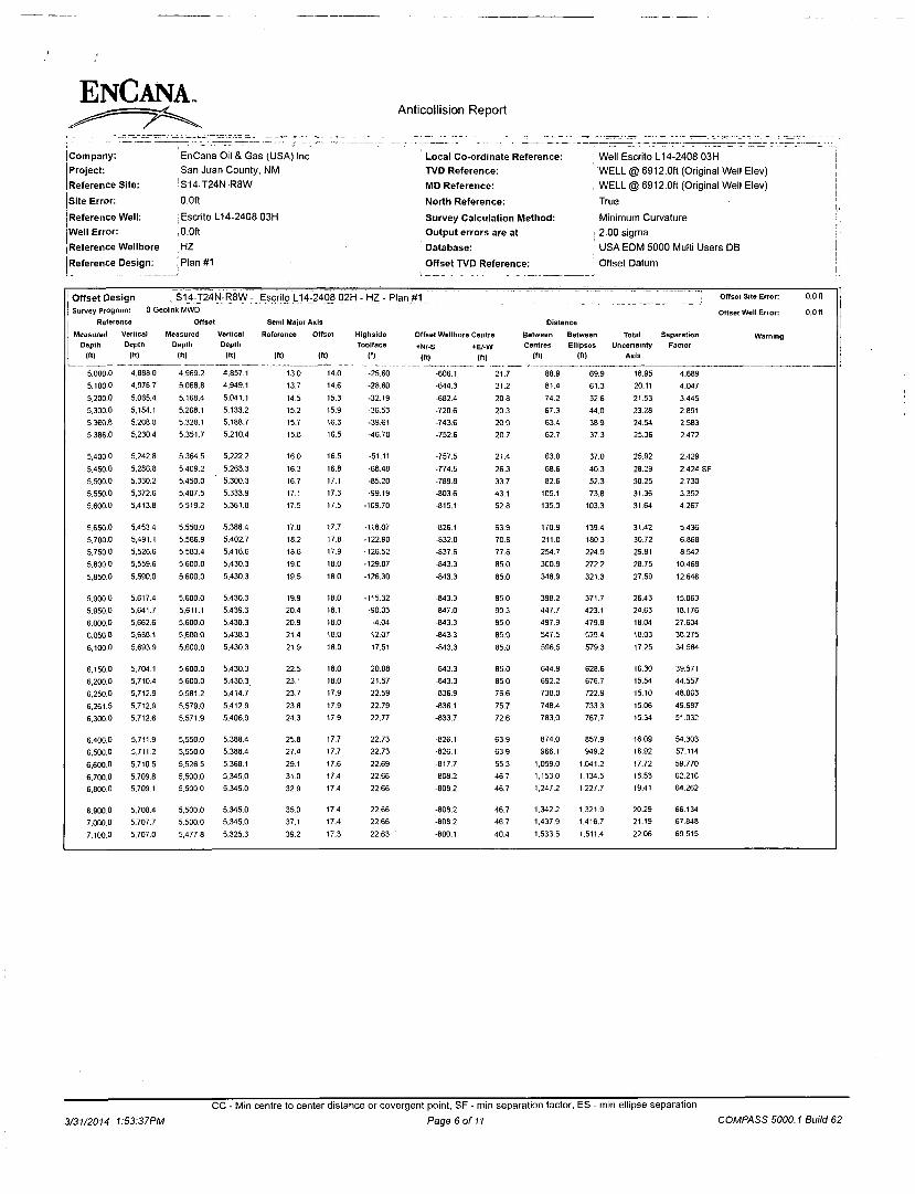
Company: Project: Reference Site: Site Error: Reference Well: Well Error: Reference Wellbore Reference Design:
EnCana Oil & Gas (USA) Inc San Juan County, NM
!S14-T24N-R8W 0.0ft
: Escrito L14-2408 03H
,0.0ft
HZ
I Plan #1
Local Co-ordinate Reference: TVD Reference: MD Reference:
North Reference:
Survey Calculation Method: Output errors are at Database:
Offset TVD Reference:
; Well Escrito L14-2408 03H WELL @ 6912.0ft (Original Well Elev)
, WELL @ 6912.0ft (Original Well Elev)
True
Minimum Curvature
; 2.00 sigma
' USA EDM 5000 Multi Users DB
; Offset Datum
j Offset Design ; S14-J24N-R8W : Escrito L14-2408 02H - HZ - Plan #1 , Offset Site Error: 0.0 ft
j Survey Program: 0-Geolink MWD
| Reference Offset Semi Major Axis Distance Offset Well Error: 0.0 ft
Measured
I Depth
j («) Vertical
Depth
(ft)
Measured
Depth
(ft)
Vertical
Depth
(ft)
Reference
(ft)
Offset
(ft)
Highside
Toolface
C)
Offset Wellbore Centre
•N/-S +E/-W
(ft) (ft)
Between
Centres
(ft)
Between
Ellipses
(ft)
Total Uncertainty
Axis
Separation Warning Factor
5.000.0 4.668.0 4,969.2 4.857.1 13,0 14.0 -25.60 -606.1 21.7 88.9 69.9 18.95 4.689
5.100.0 4.976.7 5,068.8 4.949.1 13.7 14,6 -28.60 -644.3 21.2 81.4 61.3 20.11 4.047
5.200.0 5,065.4 5,168.4 5.041.1 14.5 15.3 -32.19 -682.4 20.8 . 74.2 52.6 21.53 3.445
5.300.0 5.154.1 5.268.1 5.133.2 15.2 15.9 -36.53 -720.6 20.3 67.3 44.0 23,28 2.891
5,360.6 5.206.0 5.3281 5.188.7 15.7 16.3 -39.61 -743.6 20.0 63.4 38,9 24.54 2.583
5.386-0 5,230.4 5.351.7 5,210.4 15.8 16.5 -4670 -752.6 20.7 62.7 37.3 25.36 2.472
5,400.0 5.242.8 5.364.5 5.222.2 16.0 16.5 -51.11 -757.5 21.4 63.0 37.0 25.92 2.429
5.450.0 5,286.8 5,409.2 5.263.3 16.3 16.8 -68.48 -774.5 26.3 68.6 40.3 28.29 2.424 SF
5.500.0 5.330.2 5,450.0 5.300.3 16.7 17.1 -85.20 -789.8 33.7 82.6 52.3 30.25 2.730
5.550.0 5,372.6 5,487.5 5.333.9 17.1 17.3 -99.19 -803.6 43.1 105.1 73,6 31.36 3.352
5.600.0 5.413.8 5.519.2 5.361.8 17.5 17.5 -109.70 -815.1 52.8 135,0 103.3 31.64 4.267
5.650.0 5.453.4 5,550.0 5.388.4 17.8 17.7 -118.07 -826.1 63.9 170.8 139.4 31.42 5.436
5.700.0 5,491.1 5.566.9 5.402.7 18.2 17,8 -122.90 -832.0 70.6 211.0 180.3 30.72 6.868
5.750.0 5.526.6 5.583.4 5.416.6 18.6 17.9 -126.52 -837.6 77.6 254.7 224.9 29,81 8.542
5.800.0 5.559.6 5.600.0 5.430.3 19.0 18.0 -129.07 -843.3 85.0 300.9 272.2 28.75 10,468
5.850.0 5.590.0 5,600.0 5.430.3 19.5 18.0 -126.30 -843.3 85.0 348.9 321.3 27.59 12.646
5.900.0 5.617.4 5.600.0 5,430.3 19.9 18.0 -115.32 -843.3 85.0 398.2 371.7 26,43 15.063
5.950.0 5.641,7 5.611.1 5.439.3 20.4 18.1 -90.03 -847.0 90.3 447.7 423.1 24.63 18.176
6.000.0 5,662,6 5,600.0 5.430.3 20.9 18.0 -4.04 -843.3 85.0 497.9 479.8 18.04 27.604
6.050,0 5.680.1 5.600.0 5.430.3 21.4 18.0 12.07 -843.3 85,0 547.5 529.4 18.08 30.275
6.100,0 5,693.9 5.600.0 5.430.3 21.9 18.0 17.51 -843.3 85.0 596.5 579.3 17.25 34.584
6.150,0 5.704.1 5,600.0 5.430.3 22.5 18.0 20.08 -843.3 85.0 644.9 628.6 16.30 39.571
6,200,0 5,710.4 5,600,0 5.430.3. 23.1 18.0 21.57 -843.3 85,0 692.2 676.7 15.54 44.557
6.250.0 5,712.9 5,581.2 5.414,7 23.7 17.9 22.59 -836.9 76.6 738,0 722.9 15.10 48.863
6.261,5 5.712.9 5.579.0 5.412.9 23.8 17.9 22.79 -836.1 75.7 748.4 733.3 15.06 49.687
6,300,0 5.712.6 5.571.9 5.406.9 24.3 17.9 22.77 -833.7 72.6 783.0 767.7 15.34 51.032
6.400,0 5.711.9 5.550.0 5.388.4 25.8 17.7 22.73 -826.1 63.9 874.0 857.9 16,09 54.303
6.500.0 5.711.2 5.550.0 5,388.4 27.4 17.7 22.73 -826.1 63.9 966.1 949.2 16.92 57.114
6,600.0 5,710.5 5.526.5 5,368.1 29.1 17.6 22.69 -817.7 55.3 1,059.0 1.041.2 17.72 59.770
6.700.0 5,709.8 5,500.0 5.345.0 31.0 17.4 22.66 -808.2 467 1.153.0 1.134.5 18.53 62.216
6.800.0 5,709.1 5.500.0 5.345.0 32.9 17,4 22.66 -808.2 46.7 1,247.2 1,227.7 19.41 64.262
6.900.0 5,708.4 5,500.0 5.345.0 35.0 17.4 22.66 -808.2 46.7 1,342.2 1.321.9 20.29 66.134
7.000.0 5,707.7 5.500.0 5.345.0 37.1 17.4 22,66 -808.2 46.7 1,437.9 1,416.7 21.19 67.848
7.100.0 5.707,0 5,477,8 5.325.3 39.2 17.3 22.63 -800.1 40.4 1,533.5 1.511.4 22.06 69.515
3/31/2014 1:S3:37PM
CC - Min centre to center distance or covergent point, SF - min separation factor, ES - min ellipse separation
Page 6 of 11 COMPASS 5000.1 Build 62

ENCANA Anticollision Report
r. Company: Project: Reference Site: Site Error: Reference Well: Well Error: Reference Wellbore
L Reference Design:
EnCana Oil & Gas (USA) Inc ' San Juan County, NM
S14-T24N-R8W
,0.0ft
i Escrito L14-2408 03H 0.0ft
I HZ !Plan#1
Local Co-ordinate Reference: TVD Reference:
| MD Reference: ' North Reference:
Survey Calculation Method: Output errors are at Database:
Offset TVD Reference:
j Well Escrito L14-2408 03H
j WELL @ 6912.0ft (Original Well Elev)
; WELL @ 6912.0ft (Original Well Elev)
True
Minimum Curvature 1 2.00 sigma ! USA EDM 5000 Multi Users DB
Offset Datum
Offset Design 1 S14-T24N-R8W - Escrito L14-2408 04H - HZ - Plan #1 Offset Site Error: 0.0 ft
Survey Program: 0-Geollnk MWD Offset Well Error: 0.0 ft Reference Offset Semi Major Axis Distance
| Measured Vertical Measured Vertical Reference Offset Highside Offset Wellbore Centre Between Between Total Separation Warning j Depth Depth Depth Depth Toolface *N/-S +E/-W Centres Ellipses Uncertainty Factor
1 (ft) (ft) (ft) (ft) (ft) (ft) C) (ft) (ft) (ft) (ft) Axis
0.0 0.0 0.0 0.0 0.0 0.0 -11.85 29.5 -6.2 30.1
100.0 100.0 100.0 100.0 0.1 0.1 -11.85 29.5 -6.2 30.1 29.8 0.29 102.752
200.0 200.0 200.0 200.0 0.3 0.3 -11.85 29.5 -6,2 30.1 29.5 0.64 46.908
300.0 300.0 300.0 300.0 0,5 0.5 -11.85 29.5 -6.2 30.1 29.1 0.99 30,391
400.0 400.0 400.0 400.0 0.7 0.7 -11.85 29.5 -6.2 30.1 28.8 1.34 22.477
500.0 500.0 500.0 500.0 0.8 0.8 -11.85 29.5 -6.2 30.1 28.4 1.69 17.833
600.0 600.0 600.0 600.0 1.0 1.0 -11.85 29.5 -6.2 30.1 28.1 2.04 14.779
700.0 700.0 700.0 700.0 1.2 1.2 -11.85 29.5 -6.2 30.1 27.7 2.39 12.619
800.0 800.0 800.0 800.0 1.4 1.4 -11.85 29.5 -6.2 30.1 27.4 2.74 11.009
900.0 900.0 900.0 900.0 1.5 1.5 -11.85 29.5 -6.2 30.1 27.0 3.09 9.764
1.000.0 1.000.0 1.000.0 1.000.0 1.7 1.7 -11.85 29.5 •6.2 30.1 26.7 3.43 8.772
1.100.0 1.100.0 1.100.0 1.100.0 1.9 1.9 -11.85 29.5 -6.2 30.1 26.3 3.78 7.962
1.200.0 1.200.0 1.200,0 1.200.0 2.1 2.1 -11.85 29.5 -6.2 30.1 26.0 4.13 7.290
1.300.0 1.300.0 1,300.0 1.300.0 2.2 2.2 -11.85 29.5 -6,2 30.1 25,6 4.48 6.722
1.400.0 1.400.0 1,400.0 1.400.0 2.4 2.4 -11,85 29.5 -6.2 30.1 25.3 4.83 6.236
1.500.0 1,500.0 1,500.0 1.500.0 2.6 2.6 -11.85 29.5 -6.2 30.1 24.9 5.18 5.816
1.600.0 1.600.0 1.600.0 1.600,0 2.8 2.8 -11.85 29.5 -6.2 30.1 24.6 5.53 5.449
1.700.0 1.700.0 1.700.0 1.700.0 2.9 2.9 -11.85 29.5 -6.2 30.1 24.3 5.88 5.125
1.800.0 1,800.0 1.800.0 1.800.0 3.1 3.1 -11.85 29.5 •6.2 30.1 23.9 6.23 4.838
1.900,0 1,900.0 1.900.0 1.900.0 3.3 3.3 -11.85 29.5 -6.2 30.1 23.6 6.58 4.581
2.000.0 2.000.0 2,000.0 2.000.0 3.5 3.5 -11.85 29.5 -6.2 30.1 23,2 6.93 4.350
2.100.0 2.100.0 2.100.0 2,100.0 3.6 3.6 -11.85 29.5 -6.2 30.1 22.9 7.27 4.142
2.200.0 2,200.0 2.200.0 2.200.0 3.8 3.8 -11.85 29.5 -6.2 30.1 22.5 7.62 3.952
2.300.0 2,300.0 2.300.0 2,300.0 4.0 4.0 -11.85 29.5 -6.2 30.1 22.2 7.97 3.779
2.400.0 2.400.0 2,400.0 2.400.0 4.2 4.2 -11.85 29.5 -6.2 30.1 21.8 8.32 3.620
2,500.0 2,500.0 2,500.0 2.500.0 4.3 4.3 -11.85 29.5 -6.2 30.1 21.5 8.67 3.475
2.600.0 2.600.0 2,600.0 2.600.0 4.5 4.5 -11.85 29.5 -6.2 30.1 21.1 9.02 3.340
2.700.0 2,700.0 2,700.0 2.700.0 4 7 4.7 -11.85 29.5 -6.2 30,1 20.8 9.37 3.216
2,800.0 2,800.0 2,800.0 2.800.0 4.9 4.9 -11.85 29.5 -6.2 30.1 20.4 9.72 3.100
2.900.0 2,900.0 2.900.0 2.900.0 5.0 5.0 -11.85 29.5 -6.2 30.1 20.1 10.07 2.993
3.000.0 3,000.0 3,000.0 3.000.0 5.2 5.2 -11.85 29.5 -6,2 30.1 19,7 10.42 2.892
3.100.0 3,100.0 3,100.0 3.100.0 5.4 5.4 -11.85 29.5 -6.2 30.1 19.4 10.77 2.799
3.200.0 3.200,0 3.200.0 3.200.0 5.6 5.6 -11.85 29.5 -6.2 30.1 19.0 11.11 2.711
3.300.0 3.300.0 3,300.0 3.300.0 5.7 5.7 -11.85 29.5 -6.2 30.1 18.7 11.46 2.628
3.400.0 3.400.0 3.400.0 3.400.0 5.9 5.9 -11.85 29.5 -6.2 30.1 18.3 11.81 2.551 CC. ES. SF
3,500.0 3.500.0 3,500.0 3.500.0 6.1 6.1 167.63 29.5 -6.2 32.7 20.5 12.15 2.690
3.600.0 3,599.6 3.599.6 3.599.6 6.3 6.3 169.98 29.5 -6.2 40.4 27.9 12.47 3.239
3.700.0 3,698.8 3.698.8 3.698.8 6,5 6.4 172.37 29.5 -6.2 53.3 40.5 12.76 4.176
3.600.0 3.797.1 3.797.1 3.797.1 6.7 6.6 174.25 29.5 -6.2 71.4 58.4 13.02 5.482
3.900.0 3,894.3 3.894.3 3.894.3 6.9 6.8 175.61 29.5 -6.2 94.6 81.4 13.26 7.137
4,000.0 3.990.2 3.990.2 3.990.2 7.2 6.9 176,57 29.5 -6.2 123.0 109.5 13.47 9.130
4,100.0 4.084.4 4,084.4 4.084.4 7.6 7.1 177.25 29.5 •6.2 156.3 142.7 13.65 11.449
4,200.0 4.176.8 4,176.8 4,176.8 8.0 7.3 177.75 29.5 -6.2 194.5 180.7 13.81 14.090
4.300.0 4,2671 4,259.6 4.259.6 8.5 7.4 178.07 30.4 -6.2 238.6 224.7 13.92 17.139
4.316.6 4,281.9 4,272.5 4.272.5 8.6 7.4 178.11 30.9 -6.2 246.7 232.8 13.94 17.703
4.400.0 4,355.8 4,335.4 4,335.3 9.1 7.5 178.32 34.3 -6.3 289.2 275.0 14,19 20.375
4.500.0 4,444.5 4,407.7 4.407.3 9.6 7.7 178.48 40.8 -6.5 343.1 328.6 14.49 23.674
4.600.0 4,533,2 4.476.5 4.475.5 10.3 7,8 178.59 49.5 -67 400,1 385.3 14.79 27.060
4,700.0 4.621,9 4.541.9 4.540.0 10.9 7.9 178.65 60.0 -6.9 460.0 444.9 15.07 30.517
4.800.0 4,710.6 4.600.0 4.597.1 11.6 8.1 178.69 71.2 -7.2 522.5 507.2 15.35 34.046
4.900.0 4,799.3 4,663.8 4.659.3 12,3 8.2 178.72 85.5 -7.5 587.4 571.8 15.63 37.586
5.000.0 4.888.0 4,737.6 4.730.9 13.0 8.4 178.74 103.3 -7.9 653.6 637.6 15.92 41.041
3/31/2014 1:53:37PM
CC - Min centre to center distance or covergent point, SF - min separation factor, ES - min ellipse separation
Page 7 of 11 COMPASS 5000.1 Build 62

ENCANA. Anticollision Report
Company. Project: Reference Site: Site Error: Reference Well: iwell Error: Reference Wellbore Reference Design:
, EnCana Oil & Gas (USA) Inc San Juan County, NM S14-T24N-R8W
10.0ft Escrito L14-2408 03H
10.0ft HZ
'pian#1
Local Co-ordinate Reference: TVD Reference: MD Reference: North Reference: Survey Calculation Method: Output errors are at Database:
• Offset TVD Reference:
i Well Escrito L14-2408 03H ; WELL @ 6912.0ft (Original Well Elev) WELL @ 6912.0ft (Original Well Elev)
True
Minimum Curvature 2.00 sigma USA EDM 5000 Multi Users DB Offset Datum
I Offset Design IS14-T24JVJ-R8W- Escrito L14-2408 04H - HZ - Plan #1 J Offset Site Error: 0.0 ft
] Survey Program: 0-Geolink MWD
Reference Offset Semi Major Axis Distance Offset Well Error: 0.0 ft
i Measured
J Depth | («)
Vertical Depth
(ft)
Measured
Depth
(ft)
Vertical Depth
(n)
Reference
(ft)
Offset
(«)
Highside
Toolface
(')
Offset Wellbore Centre
+N/-S +E/-W
(ft) (ft)
Between Centres
(n)
Between
Ellipses
(It)
Total Uncertainty
Axis
Separation Factor
Warning
5.100.0 4.976.7 4.812.6 4.803.7 13.7 8.6 178.76 121.3 -8.4 719.7 703.5 16.22 44.366 5.200.0 5.065.4 4.887.7 4.876.5 14.5 8.8 178.77 139.3 -8.8 785.8 769.3 16.52 47.572 5.300.0 5,154.1 4.962.7 4.949.3 15.2 9.0 178.79 157.4 -9.2 852.0 835.1 16.82 50.666 5.360.8 5.208.0 5.008.2 4,993.6 15,7 9.1 178.79 168.3 -9.5 892.1 875.1 17.00 52.494 5.400.0 5,242.8 5.037.7 5.022.1 16.0 9.2 167.98 175.4 -9.7 918.1 900.9 17.20 53.385 5.450.0 5,286.8 5.074.9 5,058.3 16.3 9.3 155.04 184.3 -9.9 950.9 933.3 17.61 53.993
5.500.0 5.330.2 5.111.7 5.094.0 16.7 9.4 143.41 193.2 -10.1 983.4 965.2 18.17 54.134 5.550.0 5.372.6 5.147,7 5.129.0 17.1 9.5 133.27 201.9 -10.3 1,015.3 996.5 18.81 53.973 5.600.0 5,413.6 5.182.7 5.162.9 17.5 9.6 124.58 210.3 -10.5 1.046.7 1.027,2 19.51 53.658 5.650.0 5.453.4 5.216.5 5.195.8 17.8 9.7 117.19 218.4 -10.7 1,077.3 1.057.1 20.21 53.295 5.700.0 5.491.1 5.254.6 5,232.7 18,2 9.8 111.07 227.6 -12.3 1,107.2 1.086.3 20.90 52.984
5.750.0 5.526.6 5.295.0 5.271.6 18.6 10.0 105.96 237.3 -16.7 1.136.1 1,114.6 21.55 52.724
5.800.0 5.559.6 5.338.4 5.313.0 19.0 10.1 101.73 247.7 -24.6 1.163.9 1.141.7 22.16 52.519
5.850.0 5,590.0 5.385.6 5.357.2 19.5 10.3 98.30 258,8 -36.8 1.190.2 1.167.5 22.74 52.349 5.900.0 5,617.4 5.437.7 5.404.6 19.9 10.5 95.60 270.9 -54.6 1.215.1 1.191.8 23.29 52.167
5.950.0 5.641.7 5.496.1 5.455.7 20.4 10.7 93.56 284.0 -79.8 1,238.1 1.214.3 23.86 51.892
6.000.0 5.662.6 5.562.5 5.510.3 20.9 11.1 92.14 298.2 -114.7 1,259.1 1.234.6 24.50 51.383
6.050.0 5.680.1 5,638.8 5.567.7 21.4 11.6 91.28 313.3 -162.5 1.277.7 1.252.4 25.32 50.468
6.100.0 5,693.9 5.726.9 5.625.6 21.9 12.3 90.92 328.8 -227.0 1.293.4 1.266.9 26.46 48.886
6.150.0 5,704.1 5.828.3 5,679.3 22.5 13.4 90.92 343.7 -311.5 1,305,7 1.277.6 28.11 46.443
6.200.0 5.710,4 5.942.4 5,721.5 23.1 15.0 91 12 356.1 -116.6 1.314.1 1.283.6 30.44 43.164
6.250.0 5.712.9 6.066.1 5.743.3 23.7 17.1 91.34 363.7 -537.8 1.318.0 1.284.6 33.42 39.436
6,261.5 5.712.9 6.095,3 5,744.7 23.8 17.7 91.38 364.6 -567,0 1,318.2 1,284.0 34.17 38.582
6.300,0 5,712.6 6.144.8 5.744.7 24.3 18.6 91.39 365.5 -616,5 1,318.2 1,282.3 35.97 36.649
6.400.0 5.711.9 6.244.8 5,744.0 25,8 20.7 91.39 367.2 -716.4 1.318.2 1,278.0 40.19 32.799
6.500.0 5.711.2 6.344.8 5.743.3 27.4 22.8 91.39 368.9 -816.4 1.318.2 1,273.7 44.56 29.583
6.600.0 5.710.5 6.444.8 5.742.6 29.1 24.9 91.39 370.6 -916.4 1.318,2 1.269.2 49.04 26.881
6.700.0 5.709.8 6.544.8 5.741.9 31.0 27.2 91.39 372.3 -1.016.4 1,318,2 1.264.6 53.60 24.593
6.800.0 5,709.1 6,644.8 5.741.2 32.9 29.4 91.39 373.9 -1.116.4 1.318,3 1.260.0 58.23 22.639
6.900.0 5,708.4 6,744.8 5,740.5 35.0 31.7 91.39 375.6 -1,216.4 1,318.3 1.255.4 62.90 20.957
7,000.0 5.707.7 6,844.8 5.739,8 37.1 34.1 91.39 377.3 -1.316.3 1,318.3 1.250.6 67.62 19.496
7,100.0 5.707,0 6.944.8 5,739.1 39.2 36.4 91.39 379.0 -1.416.3 1,318.3 1.245.9 72.36 18.218
7.200.0 5.706.3 7.044.8 5,738.4 41.4 38.8 91.39 380.7 -1.516.3 1.318.3 1.241.1 77.13 17.092
7.300.0 5.705.6 7,144.8 5.737.7 43.6 41.2 91.39 382.4 -1.616.3 1.318.3 1.236.3 81.92 16.092
7.400.0 5.704.9 7.244.8 5,737.0 45.9 43.5 91.39 384.1 -1.716.3 1.318.3 1.231.5 86.73 15.200
7.500.0 5.704.2 7.344.8 5.736.3 48.2 45.9 91.39 385.7 -1.816.3 1.318.3 1.226.7 91.55 14.399
7.600.0 5.703.5 7.444.8 5.735.6 50.5 48.3 91.39 387.4 -1.916.2 1,318.3 1.221.9 96.39 13,677
7.700.0 5,702.9 7.544.8 5.734.9 52.8 50.8 91.39 389.1 -2.016.2 1,318.3 1.217.0 101.23 13.022
7,800.0 5,702,2 7.644.8 5.734.2 55.1 53.2 91.39 390.8 -2,116.2 1.318.3 1.212.2 106.09 12.426
7,900.0 5,701.5 7,744.8 5.733.5 57.4 55.6 91.39 392.5 -2.216,2 1.318.3 1.207.3 110.95 11.881
8.O0O.O 5.700.8 7,844.8 5,732.8 59.8 58.0 91.39 394.2 -2.316.2 1.318.3 1.202.5 115.82 11.382
8.100.0 5,700.1 7,944,8 5.732.1 62.2 60.5 91.39 395.8 -2,416.2 1.318.3 1.197.6 120.70 10.922
8.200.0 5,699.4 8,044.8 5.731.4 64.5 62.9 91.39 397.5 -2.516.1 1,318.3 1.192.7 125.58 10.497
8.300.0 5.698.7 8.144.8 5.730.7 66.9 65.3 91.39 399.2 -2.616.1 1,318.3 1.187.8 130,47 10.104
8.400.0 5,698.0 8,244.8 5.730.0 69.3 67.8 91.39 400.9 -2,716.1 1.318.3 1,182.9 135.36 9.739
8,500.0 5.697.3 8,344.8 5.729.3 71.7 70.2 91.39 402.6 -2.816,1 1.318.3 1.178.0 140.26 9.399
8.600.0 5.696.6 8,444.8 5,728.7 74.1 72.6 91.39 404.3 -2,916.1 1,318.3 1.173,1 145.16 9.082
8,700.0 5.695.9 8.544.8 5,728.0 76.5 75.1 91.39 405.9 -3.016.1 1.318.3 1,168.2 150.06 8.785
8.800.0 5.695.2 8,644.8 5.727.3 78.9 77.5 91,39 407.6 -3.116,0 1.318.3 1.163.3 154.96 8.507
8.900.0 5,694.5 8,744.8 5.726.6 81.3 80.0 91.39 409.3 -3,216.0 1.318.3 1,158.4 159.87 8.246
9.000.0 5.693.8 8,844.8 5.725.9 83.7 62.4 91.39 411.0 -3.316.0 1,318.3 1.153.5 164.78 8.000
9.100.0 5.693.1 8,944.8 5.725.2 86.2 84.9 91.39 412.7 -3.416.0 1.318.3 1,148.6 169.69 7.769
3/31/2014 1:53:37PM
CC - Min centre to center distance or covergent point, SF - min separation factor, ES - min ellipse separation
Page 8 of 11 COMPASS 5000.1 Build 62
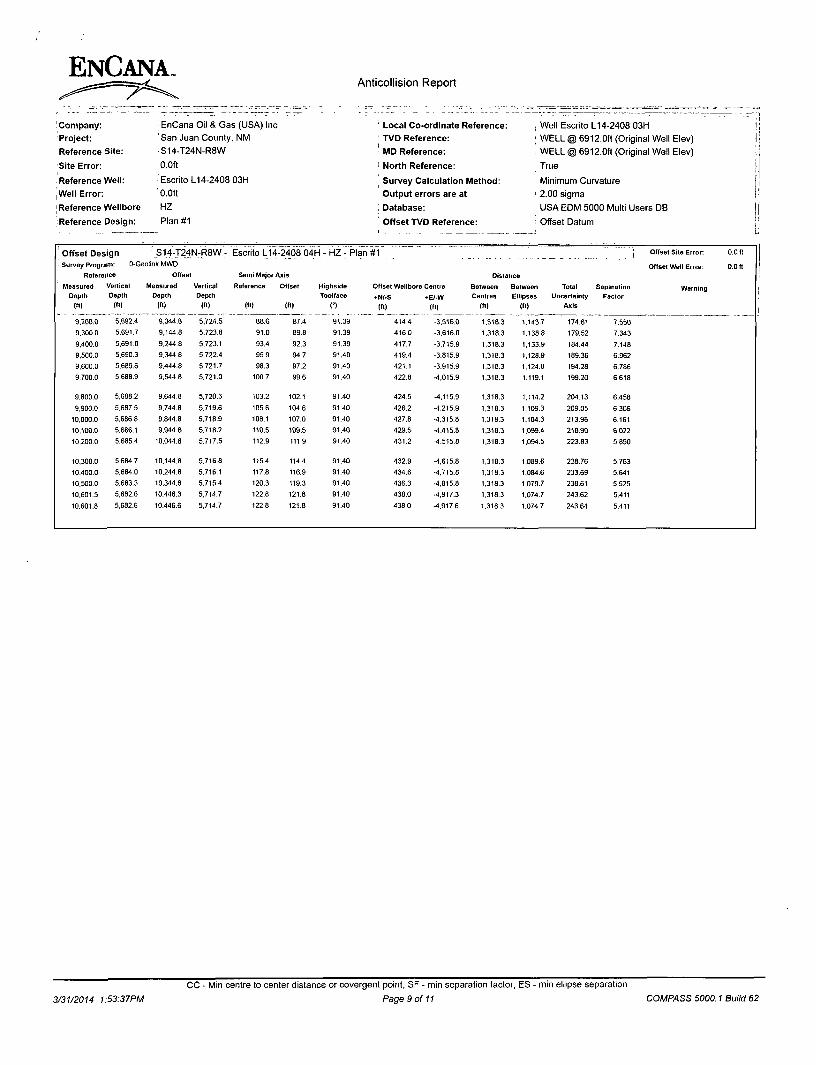
ENCANA.
! Company: Project: Reference Site: Site Error:
.'Reference Well: Well Error: [Reference Wellbore iReference Design:
Anticollision Report
EnCana Oil & Gas (USA) Inc ' San Juan County, NM S14-T24N-R8W
.0.0ft
i Escrito L14-2408 03H
' 0.0ft
HZ
'Plan#1
Local Co-ordinate Reference: TVD Reference: MD Reference: North Reference: Survey Calculation Method: Output errors are at
. Database: Offset TVD Reference:
, Well Escrito L14-2408 03H ; WELL @ 6912.0ft (Original Well Elev) WELL @ 6912.0ft (Original Well Elev) True
Minimum Curvature
' 2.00 sigma
USA EDM 5000 Multi Users DB
Offset Datum
Offset Design S14-T24N-R8W- Escrito L1< 1-2408 04H - HZ - Plan #1 . .J Offset Site Error: 0.0 ft
\ Survey Program: 0-Geolink MWD
Reference Offset Semi Major Axis Distance Offset Well Error: 0.0 ft
Measured
Depth
(«) Vertical
Depth
(ft)
Measured
Depth
(ft)
Vertical
Depth
(ft)
Reference
(ft)
Offset
Ift)
Highside
Toolface
C)
Offset Wellbore Centre
•N/-S *E/-W
(ft) (ft)
Between
Centres
(ft)
Between
Ellipses
(ft)
Total Uncertainty
Axis
Separation Factor
Warning
9.200.0 5,692.4 9,044.8 5.724.5 88.6 87.4 91.39 414.4 -3.516.0 1,318.3 1.143.7 174.61 7.550
9,300.0 5.691.7 9,144.8 5.723.8 91.0 89.8 91.39 416.0 -3.616.0 1,318.3 1.138.8 179.52 7.343
9,400.0 5,691.0 9.244.8 5.723.1 93,4 92.3 91.39 417.7 -3.715.9 1.318.3 1.133.9 184.44 7.148
9.500.0 5.690.3 9.344.8 5.722.4 95.9 94.7 91.40 419.4 -3.815.9 1.318.3 1.128.9 189.36 6.962
9,600,0 5.669,6 9.444.8 5,721.7 98.3 97.2 91.40 421.1 -3.915.9 1.318.3 1.124.0 194.28 6.786
9,700.0 5,688.9 9,544.8 5.721.0 100.7 99.6 91.40 422.8 •4,015.9 1.318.3 1,119.1 199.20 6.618
9.800.0 5,688.2 9.644.8 5.720.3 103.2 102.1 91.40 424.5 -1.115.9 1.318.3 1.114.2 204.13 6.458
9.900.0 5.687.5 9.744.8 5.719.6 105.6 104.6 91.40 426.2 -4.215.9 1.318.3 1.109.3 209.05 6.306
10,000.0 5,686.8 9.844.8 5.718.9 108.1 107.0 91.40 427.8 -4,315.8 1.318.3 1.104.3 213,98 6.161
10.100.0 5.686.1 9,944,8 5.718.2 110.5 109.5 91.40 429.5 -4,415.8 1.318.3 1.099.4 218.90 6.022
10.200.0 5,685.4 10,044.8 5.717.5 112.9 111.9 91.40 431.2 -4.515.8 1.318.3 1.094.5 223.83 5,690
10,300.0 5,684.7 10,144.8 5.716.8 115.4 114.4 91.40 432.9 -1,615.8 1.318.3 1.089.6 228.76 5.763
10.400.0 5.684.0 10,244.8 5.716.1 117.8 116.9 91.40 434.6 -1,715.8 1,318.3 1.084.6 233.69 5.641
10.500.0 5.683.3 10.344.8 5,715.4 120.3 119.3 91.40 436,3 -4,815.8 1,318.3 1.079.7 238.61 5.525
10.601.5 5,682.6 10.446,3 5.714.7 122.8 121.8 91,40 438.0 -4.917.3 1.318.3 1.074.7 243.62 5.411
10.601.8 5.682.6 10.446.6 5.714.7 122.8 121.8 91.40 438.0 -4.917.6 1.318.3 1.074.7 243.64 5.411
CC - Min centre to center distance or covergent point, SF - min separation factor, ES - min ellipse separation
3/31/2014 1:53:37PM Page 9 of 11 COMPASS 5000.1 Build 62

Anticollision Report
Company:
(Project: [Reference Site: I
jSite Error:
IReference Well:
Well Error:
[Reference Wellbore
{Reference Design:
EnCana Oil & Gas (USA) Inc San Juan County, NM
IS14-T24N-R8W
' 0.0ft
Escrito L14-2408 03H
0.0ft !HZ
iPlan #1
Local Co-ordinate Reference: TVD Reference: MD Reference:
North Reference:
Survey Calculation Method: Output errors are at Database:
Offset TVD Reference:
Well Escrito L14-2408 03H ' WELL @ 6912.0ft (Original Well Elev) WELL @ 6912.0ft (Original Well Elev) True
i Minimum Curvature 2.00 sigma
; USA EDM 5000 Multi Users DB
Offset Datum
| Offset Design S16-T24N-R8W Escrito D16A-2408 01H - Hz - Plan #2 Offset Site Error: 0.0 ft
Survey Program: 0-MWD
Reference Offset Semi Major Axis Distance Offset Well Error: 0.0 ft
, Measured i Depth
(ft)
Vertical
Depth
I f )
Measured
Depth
(ft)
Vertical
Depth
(ft)
Reference
(ft)
Offset
(ft)
Highside
Toolface
C)
Offset Wellbore Centre
+N/-S +E/.W
(ft) (ft)
Between
Centres
(ft)
Between
Ellipses
(ft)
Total Uncertainty
Axis
Separation Factor
Warning
9.800.0 5.688.2 11.816.8 5.720.5 103.2 133.4 -89.23 -979.0 -5,601.3 1.466,0 1.271.3 194.72 7.529
9,900.0 5,687.5 11.816.8 5.720.5 105.6 133.4 -89.23 -979.0 -5,601.3 1.366.3 1.169.1 197.18 6.929
10.000.0 5.686.8 11.816.8 5.720.5 108.1 133.4 -89.23 -979.0 -5.601.3 1.266.7 1.067.0 199.64 6.345
10,100.0 5.666.1 11,816.8 5.720.5 110.5 133.4 -89.23 -979.0 -5.601.3 1,167.1 965.0 202.11 5.774
10,200.0 5.665.4 11,816,6 5.720.5 112.9 133.4 -89.23 -979.0 -5,601.3 1,067.6 863.0 204.57 5.219
10.300.0 5.684.7 11.616.8 5.720.5 115.4 133.4 -89.23 -979.0 -5.601.3 968.2 761.1 207.04 4.676
10,400.0 5.684.0 11.816.8 5.720.5 117.8 133.4 -89.23 -979.0 -5,601.3 868.9 659.4 209.50 4.147
10.500,0 5,683.3 11.816.8 5.720.5 120.3 133.4 -89.23 -979.0 -5.601.3 769,8 557.8 211.97 3.632
10.601.5 5.682.6 11.816.8 5.720.5 122.8 133.4 -89.23 -979.0 -5.601.3 669.5 455.0 214.47 3.122
10.601.8 5.682.6 11.816.8 5.720.5 122.8 133.4 -89.23 -979.0 -5.601.3 669.2 454.7 214.48 3.120 CC ES, SF
3/31/2014 1:53:37PM
CC - Min centre to center distance or covergent point, SF - min separation factor, ES - min ellipse separation
Page 10 of 11 COMPASS 5000.1 Build 62

Anticollision Report
.Company:
| Project:
iReference Site:
|Site Error:
^Reference Well:
jwell Error:
; Reference Wellbore
Reference Design:
'EnCana Oil & Gas (USA) Inc
San Juan County, NM
IS14-T24N-R8W
0.0ft
| Escrito L14-2408 03H
10.0ft !HZ
Plan #1 J
j Local Co-ordinate Reference:
I TVD Reference:
MD Reference:
North Reference:
| Survey Calculation Method:
! Output errors are at
; Database:
I Offset TVD Reference: L.
' Well Escrito L14-2408 03H I WELL @ 6912.0ft (Original Well Elev) '. WELL @ 6912.0ft (Original Well Elev) | True
I Minimum Curvature 2.00 sigma USA EDM 5000 Multi Users DB Offset Datum
Reference Depths are relative to WELL @ 6912.0ft (Original Well Elev)
Offset Depths are relative to Offset Datum
Central Meridian is -107.833333 °
Coordinates are relative to: Escrito L14-2408 03H
Coordinate System is US State Plane 1983, New Mexico Western Zone
Grid Convergence at Surface is: 0.10°
1600'
c o
E 03 CL 0J CO
c
o
c 0J
O
1200
800
400
Ladder Plot
2000 4000 6000
Measured Depth
8000 10000 12000
L E G E N D
- 0 - EswtoD16A-240801H,Hz,Plan#2V0 Escrito L14-2408 01H, HZ, Plan #1 V0
EscritoL14-240802H,HZ,Plan#1 V0 -<!>- EscritoL14-240804H,HZ,Plan#1 V0
CC - Min centre to center distance or covergent point, SF - min separation factor, ES - min ellipse separation
3/31/2014 1:53:37PM Page 11 of 11 COMPASS 5000.1 Build 62

ENCANA OIL & G A S (USA) INC. ESCRITO L14-2408 #03H
1393' FSL 8.29'FWL LOCATED IN THE NW/4 SW/4 OF SECTION 14,
T24N, R8W, N.M.P.M., SAN JUAN COUNTY, NEW MEXICO
DIRECTIONS
1) FROM THE INTERSECTION OF HWY 64 & HWY 550 IN BLOOMFIELD, GO SOUTH ON HWY 550, 42.6 MILES TO CR 7997 (MP 120.7).
2) TURN LEFT AND GO 3.1 MILES TO "Y" INTERSECTION. 3) TURN RIGHT AND GO 1.2 MILES TO GATE. 4) CONTINUE THROUGH GATE AND GO 0.2 MILES TO ROAD THAT IS TO BE UPGRADED ON
RIGHT. 5) FOLLOW ROAD FOR 0.5 MILES TO EXISTING PAD WHERE ACCESS IS STAKED ON
NORTHEAST CORNER OF PAD.
WELL FLAG LOCATED AT LAT. 36.310648° N, LONG. 107.660466° W (NAD 83).
Scorpion Survey & Consulting, L.L.C _____ 302 S. Ash
JOB No.: ENC135 i isHESN^ Aztec, New Mexico 87410 DATE: 12/18/13 W ^ S & ' ( 5 0 5 > 334-4007
Sheet C

Sheet D

WELLHEAD BLOWOUT CONTROL SYSTEM
Well Name and Number: Escrito L14-2408 03H
n
5 2 5
n n n
fY?iVrr1 i f h t f f i i fWfHt
1 1 " 3K Rotating Head
1 1 " 3K Annular
3K Double Ram Top: Pipe Ram
Bot tom: Bl ind Ram 3" Outlets JMSIW, Ram
3K Mud Cross 3" gate valves
A0ASt«&£CHt«E
Related Documents