State of New Mexico Energy, Minerals and Natural Resources Department Susana Martinez Governor David Martin Cabinet Secretary David R. Catanach, Division Director Oil Conservation Division Brett F. Woods, Ph.D. Deputy Cabinet Secretary New Mexico Oil Conservation Division approval and conditions listed below are made in accordance with OCD Rule 19.15.7.11 and are in addition to the actions approved by BLM on the following 3160-3 APD form. Operator Signature Date: _3/13/2015_ Well information; Operator: Encana Oil & Gas (USA) Inc. Well Name and Number: Lybrook E12-2208 01H API#30-045-35664, Section 12, Township 22N, Range 8W Conditions of Approval: (See the below checked and handwritten conditions) X Notify Aztec OCD 24hrs prior to casing & cement. X Hold C-104 for directional survey & "As Drilled" Plat X Hold C-104 for NSL, NSP, DHC o Spacing rule violation. Operator must follow up with change of status notification on other well to be shut in or abandoned o Regarding the use of a pit, closed loop system or below grade tank, the operator must comply with the following as applicable: • A pit requires a complete C-144 be submitted and approved prior to the construction or use of the pit, pursuant to 19.15.17.8.A • A closed loop system requires notification prior to use, pursuant to 19.15.17.9.A • A below grade tank requires a registration be filed prior to the construction or use of the below grade tank, pursuant to 19.15.17.8.C o Once the well is spud, to prevent ground water contamination through whole or partial conduits from the surface, the operator shall drill without interruption through the fresh water zone or zones and shall immediately set in cement the water protection string ^Regarding Hydraulic Fracturing, review EPA Underground Injection Control Guidance 84 ^Oil base muds are not to be used until fresh water zones are cased and cemented providing isolation from the oil or diesel. This includes synthetic oils. Oil based mud, drilling fluids and solids must be contained in a steel closed loop system. ^Well-bore communication is regulated under 19.15.29 NMAC. This requires well-bore Communication to be reported in accordance with 19.15.29.8. 1220 South St. Francis Drive • Santa Fe, New Mexico 87505 Phone (505) 476-3460 • Fax (505) 476-3462 • www.emnrd.state.nm.us/ocd

Welcome message from author
This document is posted to help you gain knowledge. Please leave a comment to let me know what you think about it! Share it to your friends and learn new things together.
Transcript

State of New Mexico Energy, Minerals and Natural Resources Department
Susana Martinez Governor
David Martin Cabinet Secretary
David R. Catanach, Division Director Oil Conservation Division
Brett F. Woods, Ph.D. Deputy Cabinet Secretary
New Mexico Oil Conservation Division approval and conditions listed below are made in accordance with OCD Rule 19.15.7.11 and are in addition
to the actions approved by BLM on the following 3160-3 APD form.
Operator Signature Date: _3/13/2015_ Well information; Operator: Encana Oil & Gas (USA) Inc. Well Name and Number: Lybrook E12-2208 01H
API#30-045-35664, Section 12, Township 22N, Range 8W
Conditions of Approval: (See the below checked and handwritten conditions)
X Notify Aztec OCD 24hrs prior to casing & cement.
X Hold C-104 for directional survey & "As Drilled" Plat
X Hold C-104 for NSL, NSP, DHC
o Spacing rule violation. Operator must follow up with change of status notification on other well to be shut in or abandoned
o Regarding the use of a pit, closed loop system or below grade tank, the operator must comply with the following as applicable:
• A pit requires a complete C-144 be submitted and approved prior to the construction or use of the pit, pursuant to 19.15.17.8.A
• A closed loop system requires notification prior to use, pursuant to 19.15.17.9.A
• A below grade tank requires a registration be filed prior to the construction or use of the below grade tank, pursuant to 19.15.17.8.C
o Once the well is spud, to prevent ground water contamination through whole or partial conduits from the surface, the operator shall drill without interruption through the fresh water zone or zones and shall immediately set in cement the water protection string
^Regarding Hydraulic Fracturing, review EPA Underground Injection Control Guidance 84
^ O i l base muds are not to be used until fresh water zones are cased and cemented providing isolation from the oil or diesel. This includes synthetic oils. Oil based mud, drilling fluids and solids must be contained in a steel closed loop system.
^Well-bore communication is regulated under 19.15.29 NMAC. This requires well-bore Communication to be reported in accordance with 19.15.29.8.
1220 South St. Francis Drive • Santa Fe, New Mexico 87505 Phone (505) 476-3460 • Fax (505) 476-3462 • www.emnrd.state.nm.us/ocd

September 4, 2015 Page 2
^ P l u g pilot hole 50 feet above and below the Mancos and Gallup formation tops, and the Dakota top, if penetrated. Plugs must be WOC'd and tagged. Evaluate formation tops after drilling. Add 100% excess cement for open hole plugs.
?- Y'2o/s-NMOCD Approved by Signature Date„
OIL CONS. DIVDIST. 3
AUG 312015 Rnt3l(0-3 (March 2012)
«CEIVED
AR 1 6 2915
>m LL CONFIDENTIAL
UNITED STATES DEPARTMENT OF THE INTERIOR BUREAU OF LAND MANAGEMENT
InRM APPROVED tiMIINo KW-l l i r
Expires October 31.2014
Farmington Field Office i case s«iul No Bureau of Land ManagpwflfijM 48989A
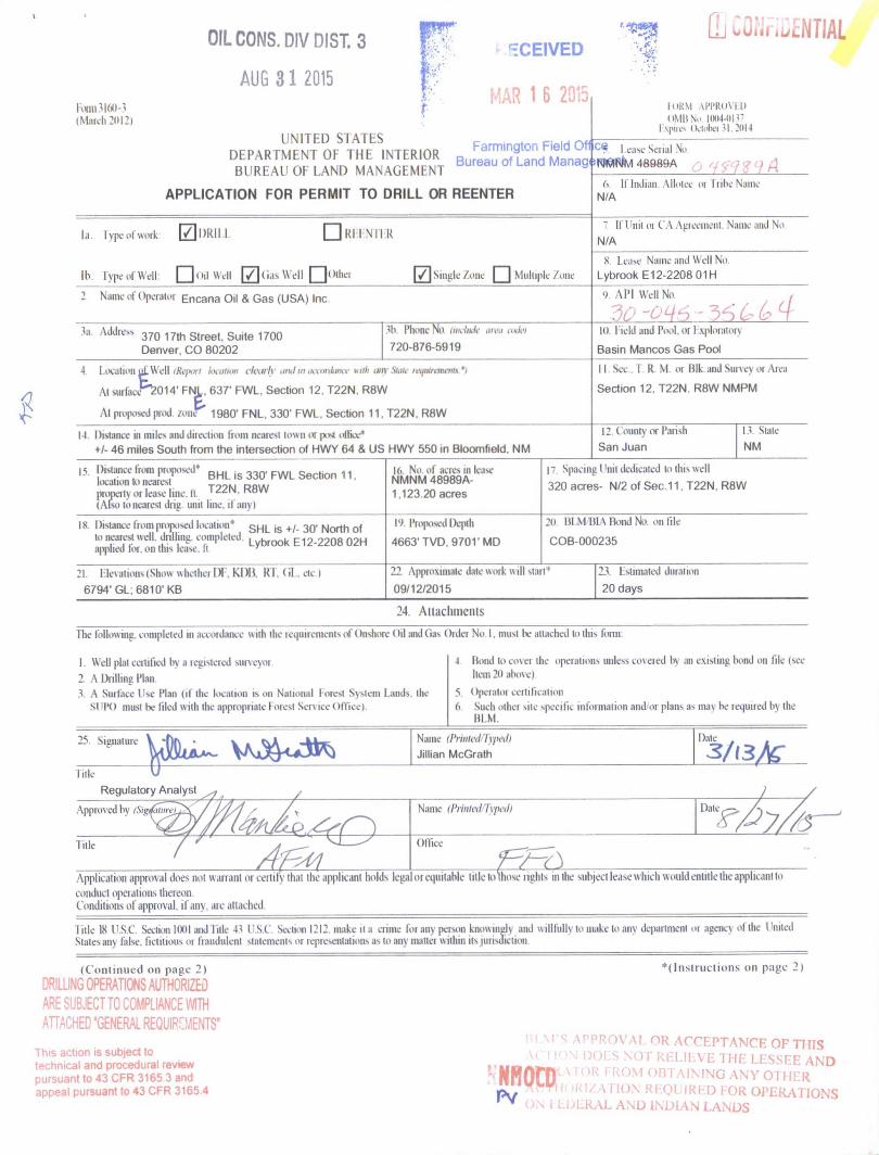
A P P L I C A T I O N F O R P E R M I T T O D R I L L O R R E E N T E R
la. type ol work [7|i)Riii •REENTER
lb. rypeofWdl: | | ] o i l Wdl 171 Gas Well | |otha f / | Single A w | ~ | Mulnpk- A>nc
Name of Operator Encana Oil & Gas (USA) Inc
3a. Address 370 17th Street. Suite 1700 Denver. CO 80202
.'Iv Phone No unclikk IH.'IJ i>«/i'i
720-876-5919
4 location of. Well dbport /ivufiiw clearly ami in mwnlmx null nil} Sink- ix^mramviy'i
Al suifacv2014' FNL, 637' FWL, Section 12. T22N. R8W
At proposed prod /one 1980' FNL, 330' FWL, Section 11, T22N, R8W
I4 Distanee in miles and direction from newest town CI JXM ollkv*
+/- 46 miles South from the intersection of HWY 64 & US HWY 550 in Bloomfield, NM
Distaneetiom proposed* S e c , j o n „ location to nearest propeny or lease line. ft. T 2 2 N R 8 W
(Also tn nearest drip unit line, il any)
IS I n * m x fromnamed location' SHL is +/- 30' North of lo nearest well, drilling eompleled applied lor. on ihis lease, Ii
Lybrook E12-2208 02H
21. Hex ations (Show w helhei I ) l . KI )l i. R I . ( i l . ele I
6794' GL;6810' KB
Id. NO. of seres in lease NMNM 48989A-1.123 20 acres
V> Pioposed Depth
4663' TVD. 9701 'MD
d If Indian Allotec oi tribe Name N/A
[f Unit Ot CA Agreement Name and No
N/A
N. Lease Name and Well No
Lybrook E12-2208 01H
9. A l ' l Well No M l WCII
10. f ield and Pool. Ot I xploratory
Basin Mancos Gas Pool
I ] Sex I R M. or Blk and Nuiw\ oi Area
Section 12. T22N. R8W NMPM
12 County or Parish
San Juan
I V Slate
NM
17 Spacing Ifnit dedicated to this well
320 acres- N/2 of Sec.11, T22N. R8W
:o HI \ l Bl \ Bond No on file
COB-000235
22 Approximate dale work will start*
09/12/2015
23. Estimated duration
20 days
24. Attachments
I he following, completed in accordance with the icipiircmcnts of Onshore Oil and (las Order No.I, must Iv attached to this form:
1. Well plat certified by a registered surveyor 2 A Drilling Plan. 3. A Surface Use Plan (if the location is on National Forest System 1 ands
si']'(> moat be tiled with ihe appropriate 1 ores) Sen ice < Iffkc). Ihe
4 Bond lo cover the operations unless covered by an existing bond on file (see Iiem2ti above)
5 Operata certification 6. Such other site specific information and oi plans as may be required by the
BLM.
* vO^»ss Name (Printed/Typed) Jillian McGrath
Date . .
1 ille
Regulatory Analyst
Approv ed by iSigi
title
Name (Printed Typed) Dale
Olliee
Application approval does not warrant or certify that the applicant holds legal ot equitable title lo those rights in the subject lease which wmild entitle the applicant lo conduct operations thereon. Conditions of approval, ifany. ate attached
Title IK USC Section 1001 and Title 4 ' I S t Section 1212. make n a crime foi am person knowingly and willfully to make to any department oi agency of the United States any false, fictitious M fraudulent statements or representations as to tan, matte within its jurisdiction
(Con t inued on page 2)
DRILLING OPERATIONS AUTHORIZED ARE SUBJECT TO COMPLIANCE WITH ATTACHED "GENERAL REQUIREMENTS"
This action is subject to technical and procedural review pursuant to 43 CFR 3165.3 and appeal pursuant to 43 CFR 3165.4
' ( I ns t ruc t i ons on page 2)
I I M S APPROVAL OR. ACCEPTANCE OF THIS ( ' ! I ' )N DOES NOT RELIEVE THE LESSFE AND
' N H O n P P O R F R 0 M OBTAINING ANY OTHER p \ ' " r V \ |. IR IZATION REQUIRED FOR OPERATIONS ' ™ ON 1 Ll jLRAL AND INDIAN LANDS

BisiBiau 1626 N. French Dr., Hobbn, N.U. 68240 Phone: (675) 303-6161 Fu: (676) 383-0720 DISTRICT D 611 S. r i n t St.. Artesia. N.U. 66210 Phone: (676) 746-1283 Fu: (676) 748-0720
DISTRICT m 1000 Rio Brazos Rd., Altec. N.U. 87410 Phone: (606) 334-6178 Fu: (606) 334-6170
DISTRICT IV 1220 S. St. French] Dr., Santa Fe, NU 67605 Phone: (606) 476-3460 Fu: (606) 478-3462
State of New Mtstico Energy, Minerals & Natural Resources Depart m f t p j t Q g j y r ^ ^
Form C-102 Revised August 1, 2011
Submit one copy to appropriate
OIL CONSERVATION DIVISION \ g 20)5 °" i C e
1220 South St. Francis Dr. Santa Fe, NM 87505 „
• AMENDED REPORT Farmington Field Office
WELL LOCATION AND ACREAGEP̂ DfOrWJCMincgLAarit 1 API Number
30-0HS- 35 'Pool Code 'Pool Name
J~){j)^l 97232 BASIN MANCOS 'Property Code •Property Name
LYBROOK E12-2208
' Well Number
01H 'OGRID No.
282327
•Operator Name
ENCANA OIL & GAS (USA) INC.
' Elevation
6794.T
1 0 Surface Location UL or lot no.
E
Section
12
Township
22N
Range
8W
Lot Idn Feet from the
2014' North/South line
NORTH Feet from the
637"
East/West line
WEST County
SAN JUAN
"Bottom Hole Location If Different From Surface UL or lot no.
E
Section
11
Township
22N
Range
8W
Lot Idn Feet from the
1980*
North/South line
NORTH
Feet from the
330'
East/West line
WEST County
SAN JUAN "Dedicated Acres PROJECT AREA
320.00 ACRES N/2 SEC. 11
"Joint or Infill 1 4 Consolidation Code "Order No.
16
NO ALLOWABLE WILL BE ASSIGNED TO THIS COMPLETION UNTIL ALL INTERESTS HAVE BEEN CONSOLIDATED OR A NON-STANDARD UNIT HAS BEEN APPROVED BY THE DIVISION
BOTTOM HOLE LAT. 36.156097' N (NAD83) LONG. 107.659081' W (NAD83) LAT. 36.156083' N (NAD27) LONG. 107.658471' W (NAD27)
ENTRY POINT lAT. 36.155993' N (NA083) LONG. 107.643590' W (NAD83) LAT. 36.1559/8' N (NAD27) LONG. 107.642980' W (NAD27)
WELL FLAG LAT. 36.155893' N (NAD83) LONG. 107.640316' W (NAD83) LAI. 36.155878' N (NAD27) LONG. 107.639706' W (NAD27)
18
CM _ P " i r > or m —
. o in
z CM ^ o in
BASIS OF BEARINGS N 89'32'21" W 5248.11' (M)
W 5252.27 3
M 33
HORIZONTAL N 89'32 '?4" W
1 1
OKU I 4574.98'
.N 87 '51 '20" W. 967.49'
Sad
o rn b „'
N 89'30 33 W 2630.51' (M) N 89'30' W 2630.75' (R)
1. LAI. 36.16154V N (NA083) LONG. 107.660129' W (NAD83) LAT. 36.161527' N (NAD27) LONG. 107.659518' W (NAD27)
2. LAT. 36.146968' N (NAD83) LONG. 10/.660295' W (NAD83) LAT. 36.146953' N (NAD27) LONG. 107.659685' W (NA027)
-i-S 8 9 ' 4 0 ' 4 0 " W 2620 .29 ' (M) S 89'46' W
2618.?1 ' (R)
S 88'54' W 5256.23' (R) S 8 9 - 5 3 ' 0 4 " W 2628 .18 ' (M)
637''®
N 0'56 W 2654.51 ' (R)
N 0 'S7 '50 " L 2656 .13 ' (M)
12
N 89 '47 14 W 2631 .67 ' (M) N 89'59' W
2630.75' (R)
4- S 89'53' W 2637.35' (R)
All C.ORNfRS rND 2j" BC GLO 194/
3. LAT. 36.101422' N (NAD83) LONG. 107.642358' W (NAD83) LAT. 36.161408' N (NAD27) LONG. 107.641748' W (NAD27)
4. I AT. 36.146943' N (NAD83) LONG. 107.642518' W (NA083) LAT. 36.146928' N (NA027) LONG. 107.641908' W (NAD2 7)
1 7 OPERATOR CERTIFICATION / hereby certify that the information contained herein is true and complete to the best of my knowledge and belief, and that this organization either owns a working interest or unleased mineral interest in the land including the proposed bottom hole location or has a right to drill this welt at this location pursuant to a contrai l with an owner of such a mineral or working interest, or to a voluntary pooling agreement or a compulsory pooling order heretofore entered by the division.
IAW UaUfo Wis-niiire 'Date Signature
J i l l i a n McGrath Printed Name
J i l l i a n . McGrath®encana . coir E-mall Address
SURVEYOR CERTIFICATION / hereby certify that the welt location shown on this plat was plotted from field notes of actual surveys madt by me or under my supervision, and that the same is true and correct to the best of my belief
APRIL 2 1 , 2014 Date of Surrey
Signature and Seal of Professional Surveyor:
Certificate Number 10201 Sheet A

Lybrook E12-2208 01H SHL: 2014" FNL, 637'FWL Sec 12 T22N R08W BHL: 1980" FNL, 330" FWL Sec 11 T22N R08W San Juan, New Mexico
Encana Oil & Gas (USA) Inc. Drilling Plan
1. ESTIMATED TOPS OF GEOLOGICAL MARKERS (TVD)
The estimated tops of important geologic markers are as follows:
Formation Depth (TVD) units = feet San Jose Fn. n/a
Nacimiento Fn. surface
Ojo Alamo Ss. 436
Kirtland Shale 645
Fruitland Coal 950
Pictured Cliffs Ss. 1,117
Lewis Shale 1,213
Cliffhouse Ss. 1,832
Menefee Fn. 2,562
Point Lookout Ss. 3,495
Mancos Shale 3,642
Mancos Silt 4,152
Gallup Fn. 4,419
Base Gallup 4,797
The referenced surface elevation is 6794', KB 6810'
2. ESTIMATED DEPTH OF POTENTIAL WATER, OIL, GAS, & OTHER MINERAL BEARING FORMATIONS
Substance Formation Depth (TVD) units = feet Water/Gas Fruitland Coal 950
Oil/Gas Pictured Cliffs Ss. 1,117 Oil/Gas Cliffhouse Ss. 1,832
Gas Menefee Fn. 2,562 Oil/Gas Point Lookout Ss. 3,495 Oil/Gas Mancos Shale 3,642 Oil/Gas Mancos Silt 4,152 Oil/Gas Gallup Fn. 4,419
All shows of fresh water and minerals will be reported and protected.
1

Lybrook E12-2208 01H SHL: 2014'FNL, 637'FWL Sec 12 T22N R08W BHL: 1980' FNL, 330' FWL Sec 11 T22N R08W San Juan, New Mexico
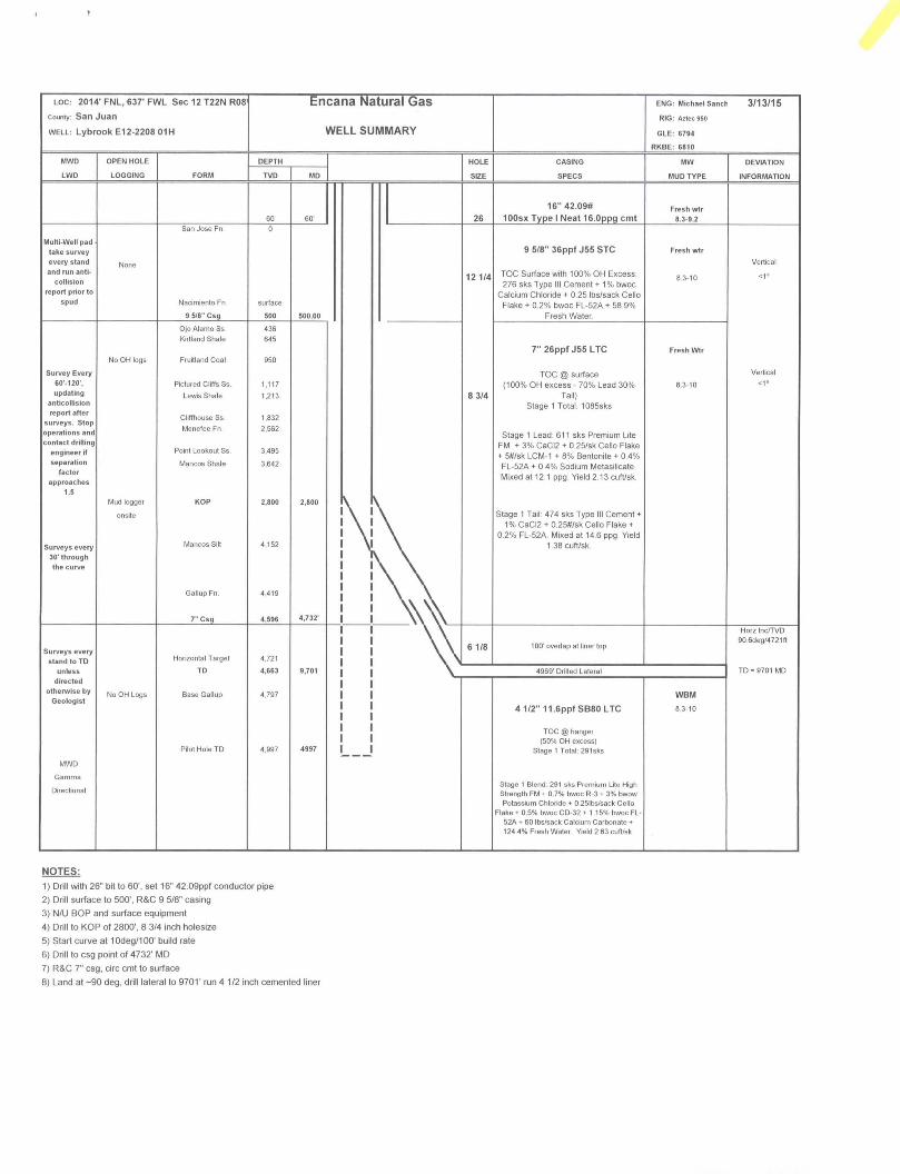
3. PRESSURE CONTROL
a) Pressure contol equipment and configuration will be designed to meet 2M standards. b) Working pressure on rams and BOPE will be 3,000 psi. c) Function test and visual inspection of the BOP will be conducted daily and noted in the IADC Daily Drilling Report. d) The Annular BOP will be pressure tested to a minimum of 50 percent of its rated working pressure. e) Blind and Pipe Rams/BOP will be tested against a test plug to 100 percent of rated working pressure. f) Pressure tests are required before drilling out from under all casing strings set and cemented in place. g) BOP controls must be installed prior to drilling the surface casing plug and will remain in use until the well is
completed or abandoned. h) BOP testing procedures and testing frequency will conform to Onshore Order No. 2. i) BOP remote controls shall be located on the rig floor at a location readily accessible to the driller. Master controls
shall be on the ground at the accumulator and shall have the capability to function all preventers. j) The kill line shall be 2-inch minimum and contain two kill line valves, one of which shall be a check valve, k) The choke line shall be a 2-inch minimum and contain two choke line valves (2-inch minimum). I) The choke and manifold shall contain two adjustable chokes, m) Hand wheels shall be installed on all ram preventers. n) Safety valves and wrenches (with subs for drill string connections) shall be available on the rig floor at all times, o) Inside BOP or float sub shall also be available on the rig floor at all times.
Proposed BOP and choke manifold arrangements are attached.
4. CASING & CEMENTING PROGRAM The proposed casing and cementing program has been designed to protect and/or isolate all usable water zones, potentially productive zones, lost circulation zones, abnormally pressured zones, and any prospectively valuable deposits of minerals. Any isolating medium other than cement shall receive approval prior to use. The casing setting depth shall be calculated to position the casing seat opposite a competent formation which will contain the maximum pressure to which it will be exposed during normal drilling operations. All indications of useable water shall be reported.
a) The proposed casing design is as follows:
Casing Depth (MD) Hole Size Csg Size Weight Grade Conductor 0'-60' 26" 16" 42.09#
Surface 0'-500' 12 1/4" 9 5/8" 36# J55, STC New Intermediate 0'-4732' 8 3/4" 7" 26# J55, LTC New
Production Liner 4632'-9701' 6 1/8" 4 1/2" 11.6# B80*, LTC New
Casing String Casing Strength Properties Minimum Design Factors Size Weight
(PPf) Grade Connectio
n Collapse
(psi) Burst (psi) Tensile (1000lbs) Collapse Burst Tensio
n 9 5/8" 36 J55 STC 2020 3520 394 1.125 1.1 1.5
7" 26 J55 LTC 4320 4980 367 1.125 1.1 1.5 4.5" 11.6 B80 LTC 6350 7780 201 1.125 1.1 1.5
*B80 pipe specifications are attached
Casing design is subject to revision based on geologic conditions encountered
2
Lybrook E12-2208 01H SHL: 2014' FNL, 637' FWL Sec 12 T22N R08W BHL: 1980' FNL, 330' FWL Sec 11 T22N R08W San Juan, New Mexico
All casing strings below the conductor shall be pressure tested to 0.22 psi per foot of casing string length or 1,500 psi, whichever is greater, but not to exceed 70 percent of the minimum internal yield. If pressure declines more than 10 percent in 30 minutes, corrective action shall be taken.
b) The proposed cementing program is as follows:
Casing Depth (MD)
Cement Volume (sacks)
Cement Type & Yield Designed TOC
Centralizers
Conductor 0'-60' 100 sks Type I Neat 16 ppg Surface None Surface 0'-500' 276 sks Type III Cement + 1% bwoc
Calcium Chloride + 0.25 lbs/sack Cello Flake + 0.2% bwoc FL-52A +
58.9% Fresh Water
Surface 1 per joint on bottom 3 joints
Intermediate 0'-4732' 100% open hole excess Stage 1 Lead:
611 sks Stage 1 Tail:
474 sks
Lead: PremLite + 3% CaCI + 0.25lb/sk CelloFlake + 5lb/sk LCM,
12.1ppg2.13cuft/sk Tail: Type III Cmt + 1% CaCI + 0.25lb/sk Cello Flake 14.5ppg
1.38cuft/sk
Surface 1 every 3 joints through water bearing zones
Production Liner
4632'-9701'
50% OH excess Stage 1 Blend Total:
291sks
Blend: Premium Lite High Strength FM + 0.7% bwoc R-3 + 3% bwow Potassium Chloride + 0.25lbs/sack Cello Flake + 0.5% bwoc CD-32 + 1.15% bwoc FL-
52A + 60 lbs/sack Calcium Carbonate + 124.4% Fresh Water.
Yield 2.63 cuft/sk
Liner Hanger
N/A
Actual volumes will be calculated and determined by conditions onsite. All cement slurries will meet or exceed minimum BLM and New Mexico Oil Conservation Division requirements. Slurries used will be the slurries listed above or equivalent slurries depending on service provider selected. Cement yields may change depending on slurries selected.
All waiting on cement times shall be a minimum of 8 hours or adequate to achieve minimum of 500 psi compressive strength at the casing shoe prior to drilling out.
5. WELL PLAN & DIRECTIONAL DRILLING PROGRAM The proposed well will be drilled in two phases. A pilot hole will be drilled in the first phase, followed by kicking off a horizontal lateral in the existing wellbore in the second phase. The intent of drilling a pilot hole is to obtain open hole log data. The intent of the second phase of the well is to plug back the pilot hole with cement to the kick off point. After plugging back, the plan is to drill a horizontal lateral from the kick off point in the existing wellbore to the proposed bottom hole location.
Description Proposed Depth (TVD/MD) Formation Vertical Pilot Hole 499774997' Gallup
Horizontal Lateral TD 466379701' Gallup
Proposed Plug Back Procedure: KOP 2800' a. Spot 500' kick plug from 2500' - 3000'
- 209 sks of Clas A cement with salt (1.3 cuft/sk yield) - Spot tuned spacer
3

Lybrook E12-2208 01H SHL: 2014' FNL, 637' FWL Sec 12 T22N R08W BHL: 1980' FNL, 330' FWL Sec 11 T22N R08W San Juan, New Mexico
6 DRILLING FLUIDS PROGRAM
Surface through ntermediate Casing 3oint:
Hole Size (in) Depth (TVD/MD) Mud Type Density (ppg) Viscosity (sec/qt) Fluid Loss (cc)
30" 0-60760' Fresh Water 8.3-9.2 38-100 4-28 12 1/4" 0'-5007500' Fresh Water 8 3-10 60-70 NC 8 3/4" 5007500'-499774997 Fresh Water LSND 8.3-10 40-50 8-10
Intermediate Casing Point to TD:
Hole Size (in) Depth (TVD/MD) Mud Type Density (ppg) Viscosity (sec/qt) Fluid Loss (cc)
8 3/4" 280072800'- Fresh Water LSND 9.5-8.8 40-50 8-10
Intermediate Casing Point to TD:
Hole Size (in) Depth (TVD/MD) Mud Type Density (ppg) Viscosity (sec/qt) Fluid Loss (cc)
6 1/8" 459674732'- Fresh Water LSND 8.3-10 15-25 <15
d) There will be sufficient mud on location to control a blowout should one occur. Mud flow and volume will be monitored both visually and with electronic pit volume totalizers. Mud tests shall be performed every 24 hours after mudding up to determine, as applicable: density, viscosity, gel strength, filtration, and pH.
V"e) A closed-loop system will be used to recover drilling fluid and dry cuttings in both phases of the well and on all hole intervals. Above-ground tanks will be utilized to hold cuttings and fluids for rig operations. A frac tank will be on location to store fresh water. Waste will be disposed of properly at an EPA-approved hazardous waste facility. Fresh water cuttings will be disposed of at Basin Disposal, Inc. and/or Industrial Ecosystems, Inc. The location will be lined in accordance with the Surface Use Plan of Operations.
7. TESTING, CORING, & LOGGING a) Drill Stem Testing - None anticipated. b) Coring - None anticipated. c) Mudd Logging - Mud loggers will be on location from kick off point to TD. d) Logging - See below
Cased Hole: CBL/CCL/GR/VDL will be run as needed for perforating control Cased Hole: CBL/CCL/GR/VDL will be run as needed for perforating control
8. ABNORMAL PRESSURES & HYDROGEN SULFIDE The anticipated bottom hole pressure is +/- 2209 psi based on a 9.0 ppg at 4721' TVD of the horizontal lateral target. No abnormal pressure or temperatures are anticipated. No hydrogen sulfide gas is anticipated, however, if H2S is encountered, the guidelines in Onshore Order No. 6 will be
9- ANTICIPATED START DATE AND DURATION OF OPERATIONS Drilling is estimated to commence on September 12, 2015. It is anticipated that completion operations will begin within 30 days after the well has been drilled depending on fracture treatment schedules with various pumping service companies.
It is anticipated that the drilling of this well will take approximately 20 days.
4
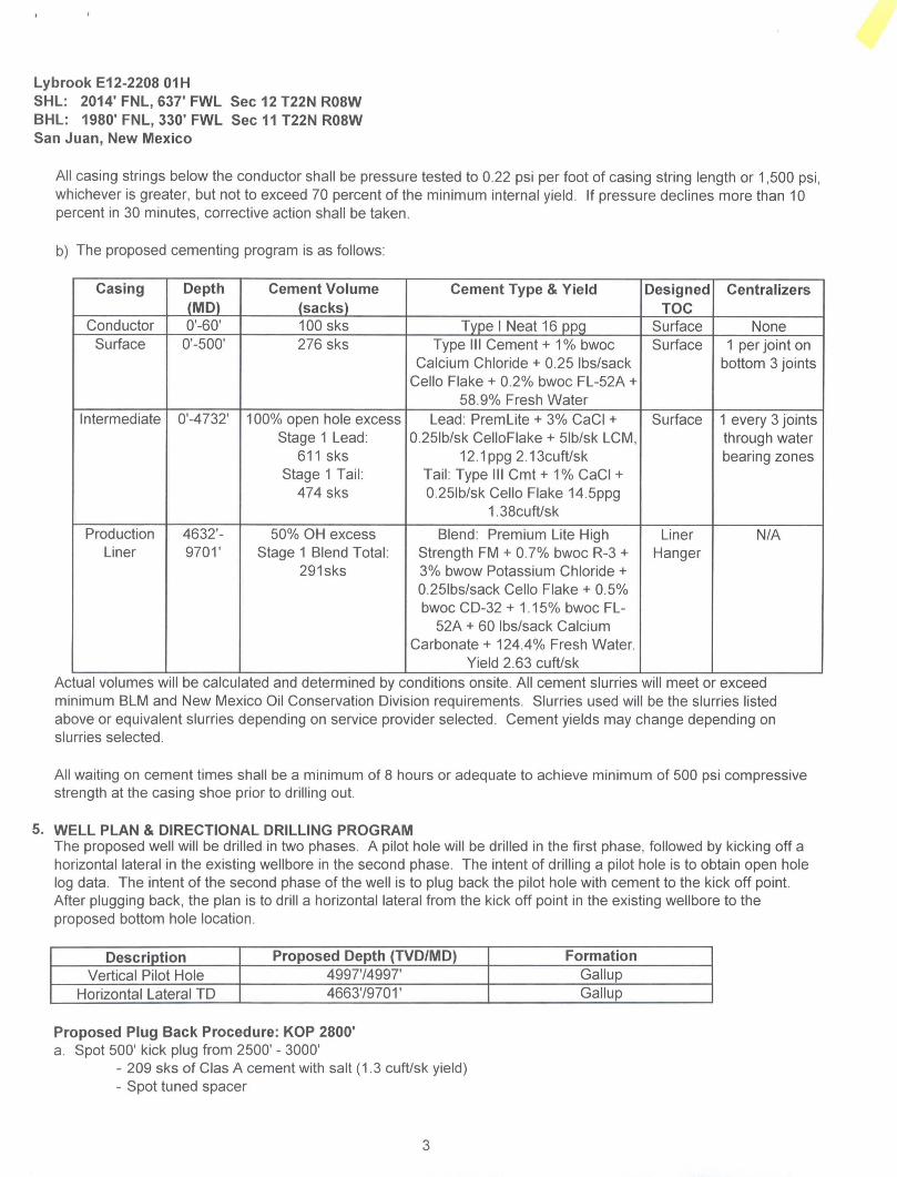
LOC: 2014'FNL, 637* FWL Sec12T22NR08 Encana Natural Gas ENG: Michael Sand 3/13/15
county: San Juan RIG: Aztec 950
WELL. Lybrook E12-2208 01H WELL SUMMARY GLE: 6794
RKBE: 6810
MWD OPEN HOLE DEPTH HOLE CASING MW DEVIATION
LWD LOGGING FORM TVD MD SIZE SPECS MUD TYPE INFORMATION
60 60' 26
16" 42.09#
100sx Type I Neat 16.0ppg cmt Fresh wtr
8.3-9.2 San Jose Fn 0
Multi-Well pad take survey every stand and run anti-
collision report prior to
spud
None
Nacimiento Fn.
9 5/8" Csg
surface
500 500.00
12 1/4
9 5/8" 36ppf J55 STC
TOC Surface with 100% OH Excess: 276 sks Type III Cement + 1 % bwoc
Calcium Chloride + 0.25 lbs/sack Cello Flake + 0.2% bwoc FL-52A + 58.9%
Fresh Water
Fresh wtr
8 3-10
Vertical
<1°
No OH logs
Ojo Alamo Ss. Kirtland Shale
Fruitland Coal
436 645
950 7" 26ppf J55 LTC Fresh Wtr
Survey Every 60'-120\ updating
anticollision report after
surveys. Stop operations and contact drilling
engineer if separation
factor approaches
1.5
Pictured Cliffs Ss.
Lewis Shale
Cliffhouse Ss
Menefee Fn.
Point Lookout Ss.
Mancos Shale
1,117
1,213
1,832
2,562
3,495
3,642
8 3/4
TOC @ surface (100% OH excess - 70% Lead 30%
Tail)
Stage 1 Total 1085sks
Stage 1 Lead: 611 sks Premium Lite FM + 3% CaCI2 + 0 25/sk Cello Flake + 5#/sk LCM-1 + 8% Bentonite + 0.4% FL-52A + 0.4% Sodium Metasilicate Mixed at 12 1 ppg Yield 2 13 cuft/sk
8.3-10
Vertical
<1" Survey Every
60'-120\ updating
anticollision report after
surveys. Stop operations and contact drilling
engineer if separation
factor approaches
1.5 Mud logger KOP 2,800 2,800
Surveys every 30' through the curve
onsite
Mancos Silt
Gallup Fn.
7" Csg
4,152
4419
4,596 4.732'
Stage 1 Tail: 474 sks Type III Cement + 1% CaCI2 + 0 25#/sk Cello Flake +
0.2% FL-52A. Mixed at 14.6 ppg Yield 1.38 cuft/sk.
Surveys every stand to TD Horizontal Target 4.721 \ >
6 1/8 100' overlap al liner top
Horz Inc/TVD 90 6deg/4721fi
unless TD 4,663 9,701 4969' Drilled Lateral TD = 9701 MD
directed otherwise by
Geologist No OH Logs Base Gallup 4,797
41/2" 11.6ppfSB80 LTC
WBM
8 3-10
Pilot Hole TD 4.997 4997
TOC @ hanger (50% OH excess)
Stage 1 Total 291sks
MWD
Gamma
Directional Stage 1 Blend: 291 sks Premium Lite High Strength FM + 07% bwoc R-3 + 3% bwow Potassium Chloride + 0.25lbs/sack Cello
Flake * 0.5% bwoc CD-32 * 1.15% bwoc FL-52A + 60 lbs/sack Calcium Carbonate + 124.4% Fresh Water. Yield 2 63 cuft/sk.
NOTES:
1) Drill with 26" bit to 60', set 16" 42 09ppf conductor pipe
2) Drill surface to 500'. R&C 9 5/8" casing
3) N/U BOP and surface equipment
4) Drill to KOP of 2800', 8 3/4 inch holesize
5) Start curve at 10deg/100' build rate
6) Drill to csg point of 4732' MD
7) R&C 7" csg. circ cmt to surface
8) Land at -90 deg. drill lateral to 9701' run 4 1/2 inch cemented liner

encana Project: San Juan County, NM
Site: S12-T22N-R8W Well: Lybrook E12-2208 01H
Wellbore: HZ Design: Plan #1
CATHEDRAL
-2000-
-1500—
-1000—
- 5 0 0 -
5 0 0 -
1000-- - Fruitland Coal -
1500-
2500—
3500-
4 0 0 0 -
4500-
Ojo Alamo Ss
Kirtland Shale
Pictured Cliffs Ss. Lewis Shale
Cliffhouse Ss.
Point Lookout Ssr
Mancos Shale —
- Mancos Silt
Gallup Fn
SECTION DETAILS
Sec MD Inc Azi TVD +N/-S +E/-W Dleg TFace VSect 1 0.0 000 0.00 0.0 0.0 0.0 0.00 0 00 0.0 2 2800.0 0.00 0.00 2800.0 0 0 0.0 0 00 0 00 0.0 3 3540.2 17.93 273.73 3528.2 7.5 -114,6 2 42 273.73 114 7 4 43198 17 93 273 73 4270.0 23.1 -354.1 0.00 0.00 354.3 5 51276 90.60 27048 4710.8 36 4 -966.5 900 -3.41 966.8 6 9701 0 90.60 270 48 4663.0 748 -55395 0.00 0.00 5539.9 0.00 5539.9 Lybrook E12-2208 01H PBHL
2 0 0 0 -
1 0 0 0 —
0 —
--1000-
-3000-
-4000—
Lybrook E12-2208 01H PBHL Lybrook E12-2208 01H POE
Start build/turn @ 4319' MO
7- ICP @ 55"
LP @ 4710' TVD; 90.6°
S11T22N-R8W
TARGET LINE
4721 ' TVD @ 0' VS; 90.6"
* | 6 3 7 |
: KOP @ 2800'
EOB; lnc=17.9"
Surface Hole Location Lybrook E12-2208 01H
Lat : 36 155893 Long : -107 640316
I I I I I I I I I I I I I I I I I I I I I I I I I I I I I I I I I I I I I I I I I I I I I I I I I I I I I I I I I I I I I I I I I I—TTT
-6000 5000 -4000 -3000 -2000 -1000 0 1000
West(-)/East(+) (1500 usft/in)
Start build/turn @ 4319' MD
C. i _ 7" ICP @ 55"
- LP @ 4710' TVD; 90 6
DESIGN TARGET DETAILS
Name Lybrook E12-2208 01H PBHL Lybrook E12-2208 01H POE
+N/-S *E/-W Northing 74 8 -5539.5 1876162.09 364 -966.5 1876132.80
Easting 2774531.57 2779104.64
Latitude 36.156097 36.155993
Longitude -107.659081 -107.643590
Horizontal Target -
5 0 0 0 -•=n
Base Gallup Lybrook E12-2208 01H POE
5500-
6000-
6500—
. M Azimuths to True North / t ^ Magnetic North: 9 38"
Magnetic Field Strength: 50094 5snT
Dip Angle: 62 91" Date: 9/5/2014
Model: IGRF2010
Lybrook E12-2208 01H PBHL
CASING DETAILS
MD 5000
47320
Name 9 5/8-
7" ICP @ 55"
Plan #1 Lybrook E12-2208 01H
14xx;x LR 16' KB @ 6810.0usft
Ground Elevation @ 6794 0 North American Datum 1983
Well Lybrook E12-2208 01H, True North
FORMATION TOP DETAILS
TVDPath MDPath Formation 4360 4360 Ojo Alamo Ss 6450 645.0 Kirtland Shale 9500 950.0 Fruitland Coal
1117 0 1117 0 Pictured Cliffs Ss 1213 0 12130 Lewis Shale 18320 1832 0 Cliffhouse Ss 2562 0 2562 0 Menefee Fn. 34939 3504 3 Point Lookout Ss. 3640 4 36582 Mancos Shale 41487 41924 Mancos Silt 4414 6 44800 Gallup Fn.
1111111111111 [ 11111111111111111111111111111111111111111111111111111111111111111111111II11111111111111111111111111111111111111111
-500 0 500 1000 1500 2000 2500 3000 3500 4000 4500 5000 5500
Vertical Section at 270.48° (1000 usft/in)
I I I I | I I I I I I I I I TTT
6000 6500

Planning Report
Database: USA EDM 5000 Multi Users DB Company: EnCana Oil & Gas (USA) Inc Project: San Juan County, NM Site: S12-T22N-R8W Well: Lybrook E12-2208 01H
Wellbore: HZ Design: Plan #1
Local Co-ordinate Reference: TVD Reference: MD Reference: North Reference: Survey Calculation Method:
Well Lybrook E12-2208 01H 16' [email protected] 16' KB @ 681 O Ousft True Minimum Curvature
Project San Juan County, NM
Map System: US State Plane 1983 System Datum: Mean Sea Level
Geo Datum: North American Datum 1983
Map Zone: New Mexico Western Zone
Site
Site Position: From: Position Uncertainty:
S12-T22N-R8W
Lat/Long
0.0 usft
Northing:
Easting:
Slot Radius:
1.876,098.31 usft Latitude: 2,780,071.21 usft Longitude:
13-3/16" Grid Convergence:
36 155893
-107.640316
0.11 °
Well
Well Position
Position Uncertainty
Lybrook E12-2208 01H
+N/-S 0.0 usft
+E/-W 0.0 usft
0.0 usft
Northing:
Easting:
Wellhead Elevation:
1,876,098.31 usft
2,780,071.21 usft
0.0 usft
Latitude:
Longitude:
Ground Level:
36 155893
-107.640316
6,794 0 usft
Wellbore HZ
Magnetics Model Name Sample Date Declination Dip Angle Field Strength <°> H (nT)
IGRF2010 9/5/2014 9.38 62.91 50.095
Design Plan #1
Audit Notes:
Version: Phase: PLAN Tie On Depth: 0.0
Vertical Section: Depth From (TVD; +N/-S +E/-W Direction (usft) (usft) (usft) n 0.0 0.0 0.0 270.48
Plan Sections
Measured Vertical Dogleg Build Turn Depth Inclination Azimuth Depth +N/-S +E/-W Rate Rate Rate TFO (usft) n O (usft) (usft) (usft) ("/IOOusft) (/IOOusft) (-/IOOusft) C) Target
0.0 0.00 0.00 0.0 0.0 0.0 0.00 0.00 0.00 0.00
2,800.0 0.00 0.00 2,8000 0 0 0.0 0.00 0.00 0.00 0.00
3.540.2 17.93 273.73 3,528.2 7 5 -114.6 2.42 2.42 0.00 273.73
4,319.8 17.93 273.73 4,270.0 23.1 -354.1 0.00 0.00 0.00 0.00
5,127.6 90.60 270.48 4,710.8 36.4 -966.5 900 9.00 -0.40 -3.41 Lybrook E12-2208 01
9,701.0 90.60 270.48 4,663.0 74.8 -5,539.5 0.00 0.00 000 0.00 Lybrook E12-2208 01
9/10/2014 3:50:59PM Page 1 COMPASS 5000.1 Build 72

Planning Report
Database: USA EDM 5000 Multi Users DB Local Co-ordinate Reference: Well Lybrook E12-2208 01H Company: EnCana Oil & Gas (USA) Inc TVD Reference: 16' KB @ 6810.0usft Project: San Juan County, NM MD Reference: 16' KB @ 6810 Ousft Site: S12-T22N-R8W North Reference: True Well: Lybrook E12-2208 01H Survey Calculation Method: Minimum Curvature
Wellbore: HZ Design: Plan #1
Planned Survey
Measured Vertical Vertical Dogleg Build Comments / Depth Inclination Azimuth Depth +N/-S +E/-W Section Rate Rate Formations (usft) n O (usft) (usft) (usft) (usft) (°/1 OOusft (7100u
0.0 0.00 0.00 0.0 0,0 0.0 0.0 0.00 0.00 100.0 0.00 0.00 1000 00 00 0.0 0.00 0.00 200.0 0.00 0.00 200.0 0 0 00 0 0 0.00 0.00 300.0 0.00 0.00 300.0 00 00 0 0 0.00 0.00 400.0 0.00 0.00 400.0 00 00 00 0.00 0.00
436.0 000 0.00 436.0 00 0.0 00 0.00 0.00 Ojo Alamo Ss. 500.0 0.00 0.00 500.0 00 00 0 0 0.00 0.00 9 5/8" 600.0 0.00 0.00 600.0 00 0.0 00 0.00 0.00 645.0 0.00 0.00 645.0 00 00 0 0 0.00 0.00 Kirtland Shale 700.0 0.00 0.00 700.0 00 0.0 00 0.00 0.00
8000 0.00 0.00 800.0 0 0 00 0 0 0.00 0.00 900.0 000 0.00 900.0 00 00 00 0.00 0.00 950.0 0.00 0.00 950.0 00 00 0 0 000 0.00 Fruitland Coal
1,000.0 0.00 0.00 1,000.0 00 00 0 0 0.00 0.00 1.100.0 000 0.00 1,100.0 00 0.0 0.0 0.00 0.00
1,117.0 0.00 0.00 1,117.0 0.0 0.0 0.0 0.00 0.00 Pictured Cliffs Ss. 1.200.0 0.00 0.00 1,200.0 0.0 00 0.0 0.00 0.00 1,213.0 0.00 0.00 1,213.0 00 0.0 0,0 0.00 0.00 Lewis Shale 1,300.0 0.00 0.00 1,300.0 00 00 0 0 0.00 0.00 1,400.0 0.00 0.00 1,400.0 00 0.0 0.0 0.00 0.00
1,500.0 0.00 0.00 1,500.0 00 0.0 0.0 0.00 0.00 1,600.0 0.00 0.00 1,600.0 0.0 0,0 00 0.00 0.00 1,700.0 0.00 0.00 1,700.0 00 00 00 0.00 0.00 1,800.0 0 00 0.00 1,800.0 0.0 00 0 0 0.00 0.00 1,832.0 0.00 0.00 1,832.0 00 00 00 0.00 0.00 Cliffhouse Ss
1,900.0 0.00 0.00 1,900.0 0.0 00 0.0 0.00 0.00 2,000.0 0.00 0.00 2,000.0 00 0.0 0.0 0.00 0.00 2,100.0 0.00 0.00 2,100.0 0.0 0.0 0 0 0.00 0.00 2,200.0 0.00 0.00 2,200.0 00 0.0 0.0 0.00 0.00 2,300.0 000 000 2,300.0 0.0 00 0 0 0.00 0.00
2,400.0 0.00 0.00 2,400.0 0 0 00 0 0 0.00 0.00 2,500.0 0.00 0.00 2,500.0 0.0 00 0 0 0.00 0.00 2,562.0 0.00 000 2,562.0 0.0 00 0.0 0.00 0.00 Menefee Fn. 2,600.0 0.00 0.00 2,600.0 00 00 0,0 0.00 0.00 2,700.0 0.00 000 2,700.0 0.0 00 0 0 0.00 0.00
2,800.0 0.00 0.00 2,800.0 00 00 0 0 0.00 0.00 KOP @ 2800' 2,900.0 2.42 273.73 2,9000 0 1 -2.1 2.1 2.42 2.42 3,000.0 4.84 27373 2,9998 0 5 84 8.4 2.42 2.42 3,100.0 7.27 273.73 3,099.2 12 -19.0 19.0 2.42 2.42 3,200.0 9.69 273.73 3,198.1 2 2 -33.7 33.7 2.42 2.42
3,300.0 12.11 273.73 3,296.3 34 -52.5 52.6 2.42 2.42 3,400.0 14.53 273.73 3,393.6 49 -75.5 75.6 2.42 242 3,500.0 16.95 273.73 3,489.8 6.7 -102.6 102.7 2.42 2.42 3,504.3 17.06 273.73 3,493.9 6 8 -1038 103.9 2.42 2.42 Point Lookout Ss. 3,540.2 17.93 273.73 3,528.2 7 5 -114.6 114.7 2.42 242 EOB; lnc=17.9°
3,600.0 17 93 273.73 3,585.1 87 -133.0 133.1 0.00 0.00 3,658.2 17.93 273.73 3,640.4 98 -150.9 150.9 0.00 0.00 Mancos Shale 3,700.0 1793 273.73 3,680.2 10.7 -163.7 163.8 0.00 0.00 3,800.0 17.93 273.73 3,775.4 12.7 -194.4 194.5 0.00 0.00 3,900.0 17.93 273.73 3,870.5 14.7 -225.2 225.3 0.00 0.00
4,000.0 17.93 273.73 3,965.6 16.7 -255.9 256.0 0.00 0.00 4,100.0 17.93 273.73 4,060.8 18.7 -2866 286.7 0.00 0.00
9/10/2014 3:50:59PM Page 2 COMPASS 5000.1 Build 72

Planning Report
Database: USA EDM 5000 Multi Users DB Local Co-ordinate Reference: Well Lybrook E12 2208 01H
Company: EnCana Oil & Gas (USA) Inc TVD Reference: 16' KB @ 6810 Ousft Project: San Juan County, NM MD Reference: 16' KB @ 6810 Ousft
Site: S12 T22N R8W North Reference: True Well: Lybrook E12 2208 01H Survey Calculation Method: Minimum Curvature
Wellbore: HZ Design: Plan #1
Planned Survey
Measured Vertical Vertical Dogleg Build Depth Inclination Azimuth Depth •N/-S +E/-W Section Rate Rate (usft) n n (usft) (usft) (usft) (usft) P I OOusft P100u
4,1924 17.93 273.73 4.148.7 20.5 -315.0 315 1 0.00 0.00 4,2000 1793 27373 4,1559 20.7 -3173 317.5 000 000 4,3000 1793 27373 4,251.1 22.7 -3480 348.2 0.00 000
4,319.8 1793 273.73 4.270.0 23.1 -354.1 354.3 0.00 0.00 4,400.0 25.13 272.73 4.344.5 24.7 3835 383.7 9.00 8.99 4,480.0 32 33 272 15 4.414.6 263 421 9 422.1 900 8.99 4.500.0 34 13 27204 4.431 3 26.7 -4328 433.0 900 8 99 4.6000 43 12 271.61 4.509.3 287 -495.2 495.4 9.00 9 00
4,700.0 52.12 271.31 4.576.7 30.6 568 9 569.2 900 900 4,732.0 55.00 271 23 4.595.7 31.1 -594.7 594.9 9.00 900 4,800.0 61.12 271.07 4.631 6 32 3 -652 3 652.6 900 900 4,9000 70 12 270.87 4.672.9 33.8 -743.3 7436 900 900 5.000.0 79 12 270.69 4,699.4 35.1 8396 8399 9.00 900
5,100.0 88 11 270.53 4.710.5 36.2 -938.9 939.2 9.00 9.00 5,127.6 90 60 270 48 4,710.8 36 4 -966.5 9668 900 900 5,200.0 90.60 270 48 4,710.0 370 -1.038.9 1,039.1 0.00 0.00 5,300.0 90 60 27048 4,7090 37.9 -1.138.9 1,139.1 0.00 0.00 5,400.0 90 60 27048 4,708.0 387 -1.238.9 1,239.1 000 0.00
5.500.0 90 60 27048 4,706.9 395 -1.338.8 1,339.1 0.00 0.00 5,600.0 90 60 270.48 4,7059 404 -1.438.8 1.439.1 0.00 000 5,700.0 90 60 270.48 4,704.8 41.2 -1.538 8 1.539 1 000 0.00 5,800 0 90 60 270.48 4.703.8 42 1 -1.638 8 1,639.1 000 0.00 5.900.0 90 60 270.48 4,702.7 429 -1.7388 1,739.1 000 0.00
6,000.0 90 60 270 48 4,701.7 43.7 -1,838 8 1,839.1 0.00 000 6.100.0 90 60 270 48 4.700.6 44.6 1.9388 1,939.1 0.00 000 6,200.0 90 60 270.48 4,699.6 45.4 -2,038 8 2,039.1 000 000 6,300.0 90 60 27048 4.698.5 463 -2,138.8 2,139.1 0.00 000 6,4000 90.60 27048 4,697.5 47.1 -2,238.8 2,239.1 000 000
6.50O.0 90 60 27048 4,696.5 47.9 -2,338.8 2.339.1 0.00 0.00 6,600.0 90 60 27048 4,6954 48.8 -2,438 7 2,439.1 0.00 0.00 6,700.0 90 60 27048 4,6944 496 2.538 7 2,539 1 0.00 000 6,800.0 90 60 27048 4,6933 505 -2.638 7 2,639 1 0.00 0.00 6,900 0 90 60 270.48 4,692.3 51 3 -2.7387 2,7390 000 0.00
7.000.0 90 60 270.48 4,691.2 52 1 2.838.7 2,8390 000 0.00 7.100.0 90 60 270 48 4.690.2 530 2.9387 2.939,0 0.00 000 7,200.0 90 60 270 48 4.689.1 53.8 -3,038.7 3,039.0 0.00 000 7,300.0 90 60 27048 4.688.1 546 -3,138.7 3,139.0 0.00 0.00 7,400.0 90 60 27048 4,687.0 55.5 -3,238 7 3.2390 000 000
7,500.0 90 60 270.48 4,686.0 563 -3.338.7 3.339.0 000 000 7,600.0 90 60 27048 4,684.9 57.2 -3,438.7 3.4390 000 000 7,700.0 90 60 270.48 4.6839 580 -3.538.6 3,539.0 000 0.00 7,800.0 90 60 270.48 4,682.9 588 3.638 6 3,639.0 000 000 7.900.0 90.60 270 48 4,681.8 597 -3,738.6 3,739.0 000 0.00
8,0000 90 60 27048 4,680.8 605 3.838.6 3.839.0 000 0.00 8,100.0 90 60 270.48 4,6797 61 4 -3,938.6 3,939.0 0.00 000 8,200.0 90 60 270 48 4,678.7 622 -4,038.6 4,039.0 0.00 000 8,3000 90.60 270 48 4,677.6 630 -4,138.6 4,139.0 0.00 0.00 8,400.0 90 60 270.48 4,676.6 639 -4,2386 4,239.0 0.00 000
8,500.0 90 60 27048 4,675.5 647 -4,338.6 4,339.0 000 000 8.600.0 90 60 270.48 4.674.5 656 -4,4386 4.4390 000 000 8,700.0 90.60 270 48 4.673.4 66 4 -4,538.6 4.5389 0.00 000 8.800.0 90 60 270.48 4,6724 67.2 -4.638.5 4.638.9 0.00 0.00
Comments / Formations
7" ICP @ 55°
! 4710' TVD; 90.6° - Lybrook E12 2208 011
9/10/2014 3:5059PM Page 3 COMPASS 5000 1 Build 72

Planning Report
Database: USA EDM 5000 Multi Users DB Local Co-ordinate Reference: Well Lybrook E12-2208 01H Company: EnCana Oil & Gas (USA) Inc TVD Reference: 16' KB@6810 0usft Project: San Juan County, NM MD Reference: 16' KB @ 6810 Ousll Site: S12-T22N-R8W North Reference: True Well: Lybrook E12-2208 01H Survey Calculation Method: Minimum Curvature Wellbore: HZ Design: Plan #1
Planned Survey
Measured Vertical Vertical Dogleg Build Depth Inclination Azimuth Depth +N/-S +E/-W Section Rate Rate (usft) PI n (usft) (usft) (usft) (usft) ("/IOOusft C/100u
8,900.0 90.60 270.48 4,671.4 68.1 4.738.5 4,738.9 0.00 0.00
9,000.0 90.60 27048 4,670.3 689 -4.838.5 4,838.9 0.00 0.00 9,100.0 90.60 270.48 4,6693 69.8 4.938.5 4.938.9 000 0.00 9,2000 90.60 270.48 4,668.2 706 -5,038 5 5.038.9 0.00 0.00 9,300.0 90.60 270.48 4,667 2 71.4 -5,138.5 5.1389 0.00 0.00 9,400.0 90.60 270.48 4,666,1 72.3 -5,238.5 5,238.9 0.00 0.00
9,500.0 90 60 270.48 4,665.1 73.1 -5,338.5 5,338.9 0.00 0.00 9,600.0 90 60 270.48 4,664.0 73.9 -5,438.5 5,438.9 0.00 0.00 9,700.0 90 60 270.48 4,663.0 748 -5,538.5 5,538.9 0.00 0.00 9,701.0 90.60 270.48 4,663.0 748 -5,539.5 5,539.9 0.00 0.00 "
Comments / Formations
0.00 TD at 9701.0 Lybrook E12-2208 01H PBHL
Targets
Target Name - hit/miss target Dip Angle - Shape O
Dip Dir.
n TVD (usft)
+N/-S (usft)
+EV-W (usft)
Northing (usft)
Easting (usft) Latitude Longitude
Lybrook E12-2208 01H 1 0.00 - plan hits target center - Point
0.00 4,663.0 748 -5,539.5 1,876,162.09 2,774,531.57 36.156097 -107.659081
Lybrook E12-2208 01HI 0.00 - plan hits target center - Point
0.00 4,710.8 36.4 966.5 1,876,132.80 2,779.104.64 36.155993 -107.643590
Casing Points
Measured Depth (usft)
500.0
4,732.0
Vertical Depth (usft)
500.0 9 5/8"
4,595.7 7" ICP @ 55°
Name
Casing Diameter
(")
Hole Diameter
(")
Formations
Measured Depth (usft)
436.0
645.0
950.0
1,117.0
1,213.0
1,832.0
2,562.0
3,504.3
3,658.2
4,192.4
4,480.0
Vertical Depth (usft)
436.0
645.0
9500
1,117.0
1,213.0
1,832.0
2,562 0
3,495.0
3,6420
4,152.0
4,419.0
Name Lithology
Ojo Alamo Ss.
Kirtland Shale
Fruitland Coal
Pictured Cliffs Ss.
Lewis Shale
Cliffhouse Ss.
Menefee Fn.
Point Lookout Ss.
Mancos Shale
Mancos Silt
Gallup Fn
Dip
n -0.60
-0.60
060
060
-0.60
-0.60
-0.60
060
-0.60
-060
060
Dip
Direction
PI 270.48
270.48
270.48
270.48
270.48
270.48
270.48
270.48
270.48
270.48
270.48
9/10/2014 3:50 59PM Page 4 COMPASS 5000.1 Build 72

Planning Report
Database: USA EDM 5000 Multi Users DB Local Co-ordinate Reference: Well Lybrook E12-2208 01H
Company: EnCana Oil & Gas (USA) Inc TVD Reference: 16' KB@6810 0usft Project: San Juan County, NM MD Reference: 16' KB @ 6810.0usft
Site: S12 T22N R8W North Reference: True Well: Lybrook E12-2208 01H Survey Calculation Method: Minimum Curvature
Wellbore: HZ Design: Plan#1
Plan Annotations
Measured Vertical Local Coordinates Depth Depth +N/-S +E/-W (usft) (usft) (usft) (usft) Comment
2.800.0 2.800.0 0.0 0 0 KOP @ 2800' 3.540 2 3.528 2 7.5 114 6 EOB;lnc=17 9° 4.319 8 4,270.0 23.1 -354 1 Start build/turn @ 4319'MD 5.127.6 4.710.8 36.4 966 5 LP @ 4710' TVD; 90.6° 9.701 0 4.663.0 74.8 5.539 5 TD at 9701 0
9/10/2014 3:50:59PM Page 5 COMPASS 5000 1 Build 72

Lybrook E12-2208 01H SHL: SWNW Section 12, T22N, R8W
2014 FNL and 637 FWL BHL: SWNW Section 11, T22N, R8W
1980 FNL and 330 FWL San Juan County, New Mexico Lease Number: NMNM 48989A
Topsoil will be stockpiled separate from subsoil with a noticeable gap left between the stockpiles. Vehicle/equipment traffic will be prevented from crossing topsoil stockpiles.
Topsoil will not be stripped when soils are moisture-saturated or frozen below the stripping depth.
If the location becomes prone to wind or water erosion, Encana will take appropriate measures to prevent topsoil loss from wind. Such measures may include using tackiflers or water to wet the topsoil stockpile so that a crust is created across the exposed soil to prevent soil loss.
All construction materials for the well pad will consist of native borrow and subsoil accumulated during well pad construction. If additional fill or surfacing material is required, it will be obtained from existing permitted or private sources and will be hauled in by trucks over existing access roads.
The maximum cut will be approximately 12.7 feet in (corner 3) and the maximum fill will be approximately 10.0 feet between (corner 5 and corner 6).
As determined during the onsite on July 17, 2014, the following best management practices will be implemented: a. Water will be diverted around the pad and silt traps installed as needed upon interim
reclamation. b. Silt trap will be constructed in E.O.D. between (corner 2 and corner3).
Construction equipment may include chain saws, a brush hog, scraper, maintainer, excavator, and dozer. Construction for the access road and well pad will take approximately 2 to 4 weeks.
C. Pipeline See the Plan of Development submitted with the final modifications to the Standard SF-299 Application for authorization to construct, operate, maintain and terminate a 1257 foot, up to 6-inch outside diameter, buried steel well connect pipeline that was submitted to the BLM concurrently with the APD.
7. METHODS FOR HANDLING WASTE A. Cuttings
1. A closed-loop system will be used. Cuttings will be moved through a shaker system on the drill rig that separates drilling fluids from the cuttings. Cuttings will be stored onsite in above-ground storage tanks. Cuttings will be pulled from the storage tanks, mixed with saw dust or similar absorbent material, and disposed of at the Envirotech, Inc. and/or Industrial Ecosystem, Inc. waste disposal facilities.
2. The closed-loop system storage tanks will be adequately sized to ensure confinement of all fluids and will provide sufficient freeboard to prevent uncontrolled releases.
3. A 20-mil liner will be installed under tanks, pumps, ancillary facilities, and truck loading/unloading areas associated with the closed-loop system.
B. Drilling Fluids
-6 -

ENCANA OIL & GAS (USA) INC. LYBROOK E12-2208 #01H
2014' FNL & 637' FWL LOCATED IN THE SW/4 NW/4 OF SECTION 12,
T22N, R8W, N.M.P.M., SAN JUAN COUNTY, NEW MEXICO
DIRECTIONS
2) )
1) FROM THE INTERSECTION OF HWY 64 & HWY 550 IN BLOOMFIELD, GO SOUTH ON HWY 550, 39.0 MILES TO INDIAN ROUTE 7061 (M.P. 112.6). TURN RIGHT AND GO 7.0 MILES. TURN LEFT ONTO 2-TRACK, WHERE ACCESS IS STAKED
WELL FLAG LOCATED AT LAT. 36.155893° N, LONG. 107.640316° W (NAD 83).
JOB No.: ENC143 DATE: 04/28/14
WELLHEAD BLOWOUT CONTROL SYSTEM
encana Well Name and Number: Lybrook E12-2208 01H
1 1 " 3K Rotat ing Head
1 1 " 3K Annular
61—1—h
3K Double Ram Top: Pipe Ram
Bot tom: Bl ind Ram 3" Outlets Below Ram
3K Mud Cross 3" gate valves
ttMlU>«E
Related Documents