Seminar report CorDECT INTRODUCTION corDECT is an advanced, field proven, Wireless Access System developed by Midas Communication Technologies and the Indian Institute of Technology, Madras, in association with Analog Devices Inc., USA corDECT provides a complete wireless access solution for new and expanding telecommunication networks with seamless integration of both voice and Internet services. It is the only cost-effective Wireless Local Loop (WLL) system in the world today that provides simultaneous toll-quality voice and 35 or 70 kbps Internet access to wireless subscriber. CorDECT is based on the DECT standard specification from the European Telecommunication Standards Institute (ETSI). In addition, it incorporates new concepts and innovative designs brought about by the collaboration of a leading R & D company, a renowned university, and a global semiconductor manufacturer. This alliance has resulted in many break through concepts including that of an Access Network that segregates voice and Internet traffic and delivers each, in the most efficient manner, to the telephone network and the Internet respectively, without one choking the other. This seminar contains a brief description of the various corDECT sub- systems that make it scalable and modular. Next, the several ways in which corDECT can be deployed to cater to a wide variety of subscriber densities and tele traffic levels, to suit both incumbent and green field operator’s .The dimensioning of the corDECT system to cater to the required voice and Internet traffic levels. 1 Electronics & communication Gptc.nta

Welcome message from author
This document is posted to help you gain knowledge. Please leave a comment to let me know what you think about it! Share it to your friends and learn new things together.
Transcript

Seminar report CorDECT
INTRODUCTION
corDECT is an advanced, field proven, Wireless Access System developed
by Midas Communication Technologies and the Indian Institute of Technology,
Madras, in association with Analog Devices Inc., USA
corDECT provides a complete wireless access solution for new and
expanding telecommunication networks with seamless integration of both voice
and Internet services. It is the only cost-effective Wireless Local Loop (WLL)
system in the world today that provides simultaneous toll-quality voice and 35 or
70 kbps Internet access to wireless subscriber.
CorDECT is based on the DECT standard specification from the European
Telecommunication Standards Institute (ETSI). In addition, it incorporates new
concepts and innovative designs brought about by the collaboration of a leading R
& D company, a renowned university, and a global semiconductor manufacturer.
This alliance has resulted in many break through concepts including that of an
Access Network that segregates voice and Internet traffic and delivers each, in the
most efficient manner, to the telephone network and the Internet respectively,
without one choking the other.
This seminar contains a brief description of the various corDECT sub-
systems that make it scalable and modular. Next, the several ways in which
corDECT can be deployed to cater to a wide variety of subscriber densities and tele
traffic levels, to suit both incumbent and green field operator’s .The dimensioning
of the corDECT system to cater to the required voice and Internet traffic levels.
1Electronics & communication Gptc.nta
Seminar report CorDECT
Highlights the coverage achieved by different configurations. A system with active
elements at each subscriber location, apart from several Base Station sites, requires
a sophisticated and user-friendly Network Management System (NMS) for
monitoring and maintenance. This report gives a glimpse of the future, as
corDECT evolves to a fullfledged3G+ system with advanced features such as fast
download from the Internet.
Finally, there is an Appendix that gives a brief overview of the DECT
standard. The main aspects of DECT are dealt with here, in particular MCTDM A
medium-access and Dynamic Channel Selection. A short list of key DECT
physical parameters is also included.
CorDECT WIRELESS ACCESS SYSTEM
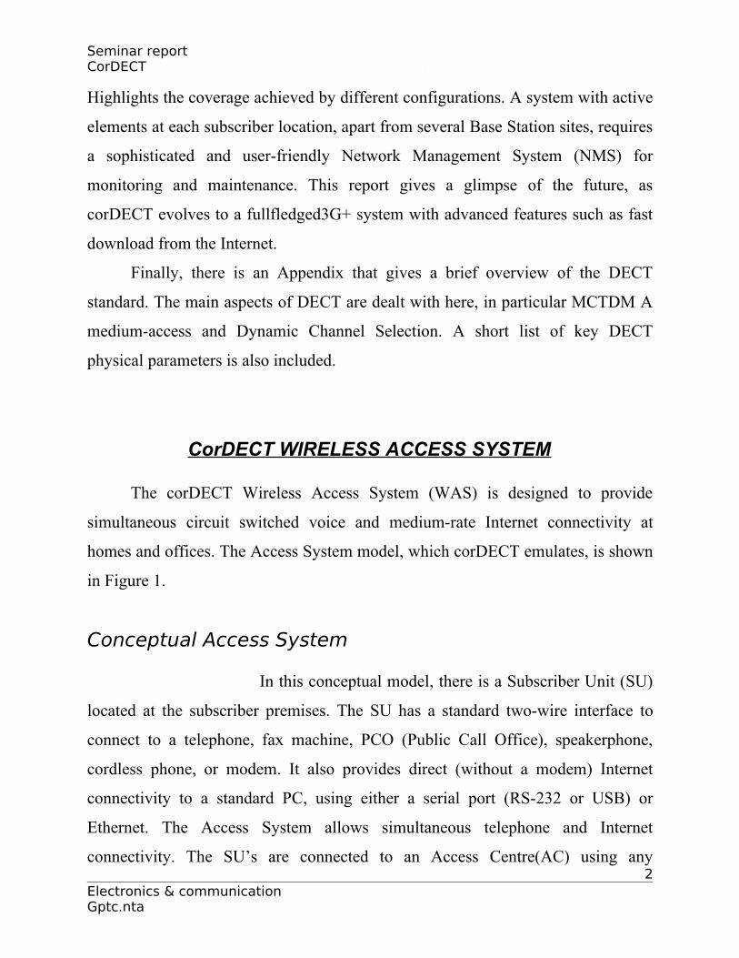
The corDECT Wireless Access System (WAS) is designed to provide
simultaneous circuit switched voice and medium-rate Internet connectivity at
homes and offices. The Access System model, which corDECT emulates, is shown
in Figure 1.
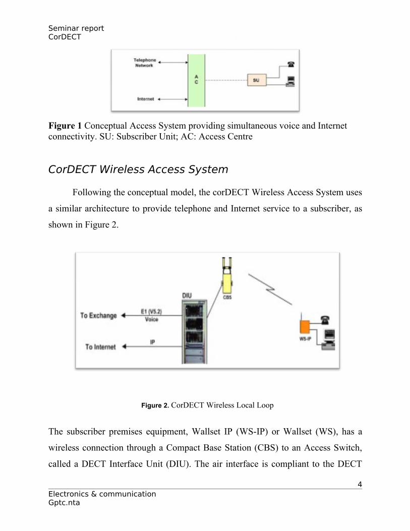
Conceptual Access System
In this conceptual model, there is a Subscriber Unit (SU)
located at the subscriber premises. The SU has a standard two-wire interface to
connect to a telephone, fax machine, PCO (Public Call Office), speakerphone,
cordless phone, or modem. It also provides direct (without a modem) Internet
connectivity to a standard PC, using either a serial port (RS-232 or USB) or
Ethernet. The Access System allows simultaneous telephone and Internet
connectivity. The SU’s are connected to an Access Centre(AC) using any 2
Electronics & communication Gptc.nta

Seminar report CorDECT
convenient technology like wireless, plain old copper, DSL on copper, coaxial
cable, optical fiber, or even power lines.
The AC must be scalable, serving as few as 200subscribers and as many as
2000 subscribers .In urban areas, the AC could be located at street corner, serving a
radius of 700 m to 1 km. This small radius in urban areas is important for wireless
access, in order to enable efficient reuse of spectrum. When cable is used, the small
radius ensures lower cost and higher bit rate connectivity. However in rural areas,
the distance between the AC and the SU could easily be10 km and even go up to
25 km in certain situations. The AC is thus a shared system catering to multiple
subscribers. The voice and Internet traffic to and from subscribers can be
concentrated here and then carried on any appropriate backhaul transport network
to the telephone and Internet networks respectively.
At the AC, the telephone and Internet traffic is separated. The telephone
traffic is carried to the telephone network on E1 links using access protocols such
as V5.2. The Internet traffic from multiple subscribers is statistically multiplexed,
taking advantage of the busty nature of Internet traffic, and carried to the Internet
network. As use of Voice-over-IP (VoIP) grows, voice traffic from SU’s could also
be sent to the Internet, gradually making connectivity to the telephone network
redundant. However, for connecting to the legacy telephone network, the voice
port of the AC may be required for some time to come .An AC could also
incorporate switching and maintenance functions when required. Further, it is
possible to co-locate Internet servers with the AC.
3Electronics & communication Gptc.nta
Seminar report CorDECT
Figure 1 Conceptual Access System providing simultaneous voice and Internet connectivity. SU: Subscriber Unit; AC: Access Centre
CorDECT Wireless Access System
Following the conceptual model, the corDECT Wireless Access System uses
a similar architecture to provide telephone and Internet service to a subscriber, as
shown in Figure 2.
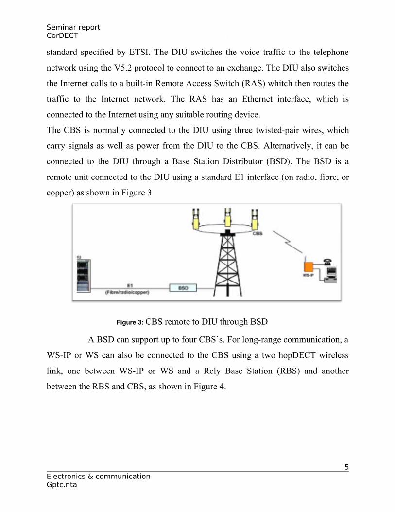
Figure 2. CorDECT Wireless Local Loop
The subscriber premises equipment, Wallset IP (WS-IP) or Wallset (WS), has a
wireless connection through a Compact Base Station (CBS) to an Access Switch,
called a DECT Interface Unit (DIU). The air interface is compliant to the DECT
4Electronics & communication Gptc.nta
Seminar report CorDECT
standard specified by ETSI. The DIU switches the voice traffic to the telephone
network using the V5.2 protocol to connect to an exchange. The DIU also switches
the Internet calls to a built-in Remote Access Switch (RAS) whitch then routes the
traffic to the Internet network. The RAS has an Ethernet interface, which is
connected to the Internet using any suitable routing device.
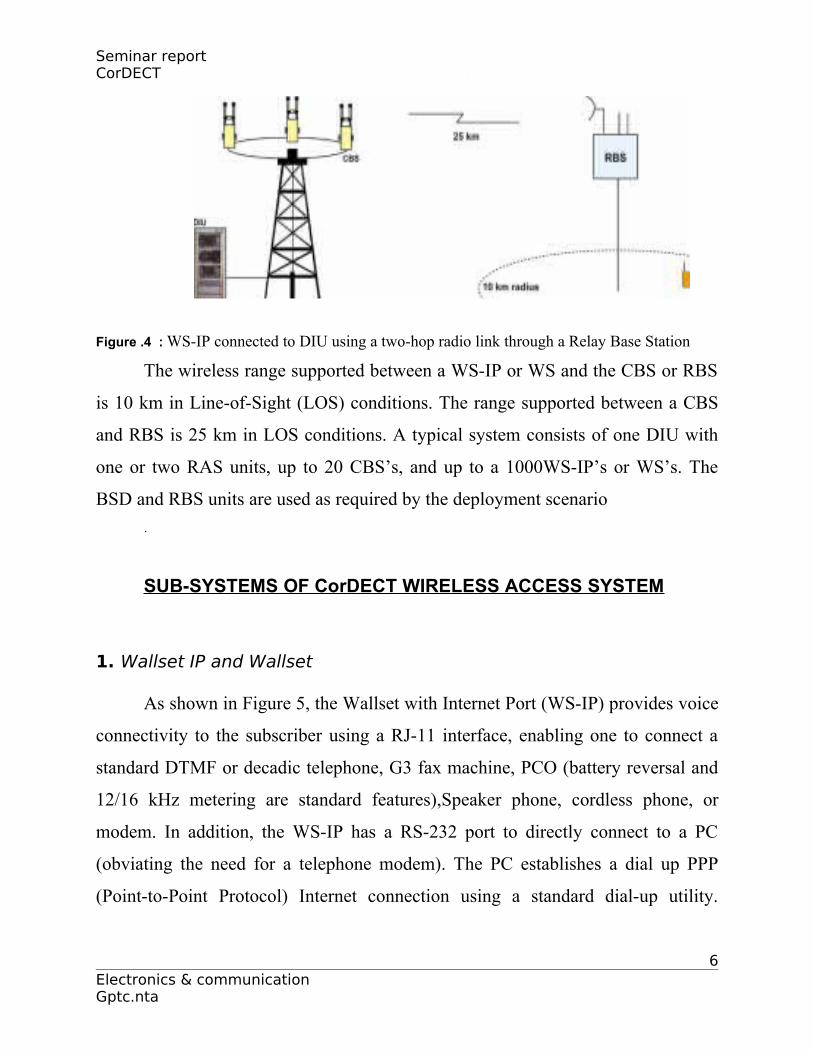
The CBS is normally connected to the DIU using three twisted-pair wires, which
carry signals as well as power from the DIU to the CBS. Alternatively, it can be
connected to the DIU through a Base Station Distributor (BSD). The BSD is a
remote unit connected to the DIU using a standard E1 interface (on radio, fibre, or
copper) as shown in Figure 3
Figure 3: CBS remote to DIU through BSD
A BSD can support up to four CBS’s. For long-range communication, a
WS-IP or WS can also be connected to the CBS using a two hopDECT wireless
link, one between WS-IP or WS and a Rely Base Station (RBS) and another
between the RBS and CBS, as shown in Figure 4.
5Electronics & communication Gptc.nta
Seminar report CorDECT
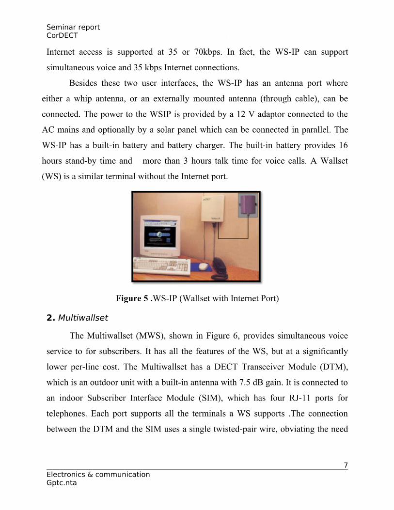
Figure .4 : WS-IP connected to DIU using a two-hop radio link through a Relay Base Station
The wireless range supported between a WS-IP or WS and the CBS or RBS
is 10 km in Line-of-Sight (LOS) conditions. The range supported between a CBS
and RBS is 25 km in LOS conditions. A typical system consists of one DIU with
one or two RAS units, up to 20 CBS’s, and up to a 1000WS-IP’s or WS’s. The
BSD and RBS units are used as required by the deployment scenario
.
SUB-SYSTEMS OF CorDECT WIRELESS ACCESS SYSTEM
1. Wallset IP and Wallset
As shown in Figure 5, the Wallset with Internet Port (WS-IP) provides voice
connectivity to the subscriber using a RJ-11 interface, enabling one to connect a
standard DTMF or decadic telephone, G3 fax machine, PCO (battery reversal and
12/16 kHz metering are standard features),Speaker phone, cordless phone, or
modem. In addition, the WS-IP has a RS-232 port to directly connect to a PC
(obviating the need for a telephone modem). The PC establishes a dial up PPP
(Point-to-Point Protocol) Internet connection using a standard dial-up utility.
6Electronics & communication Gptc.nta
Seminar report CorDECT
Internet access is supported at 35 or 70kbps. In fact, the WS-IP can support
simultaneous voice and 35 kbps Internet connections.
Besides these two user interfaces, the WS-IP has an antenna port where
either a whip antenna, or an externally mounted antenna (through cable), can be
connected. The power to the WSIP is provided by a 12 V adaptor connected to the
AC mains and optionally by a solar panel which can be connected in parallel. The
WS-IP has a built-in battery and battery charger. The built-in battery provides 16
hours stand-by time and more than 3 hours talk time for voice calls. A Wallset
(WS) is a similar terminal without the Internet port.
Figure 5 .WS-IP (Wallset with Internet Port)
2. Multiwallset
The Multiwallset (MWS), shown in Figure 6, provides simultaneous voice
service to for subscribers. It has all the features of the WS, but at a significantly
lower per-line cost. The Multiwallset has a DECT Transceiver Module (DTM),
which is an outdoor unit with a built-in antenna with 7.5 dB gain. It is connected to
an indoor Subscriber Interface Module (SIM), which has four RJ-11 ports for
telephones. Each port supports all the terminals a WS supports .The connection
between the DTM and the SIM uses a single twisted-pair wire, obviating the need
7Electronics & communication Gptc.nta

Seminar report CorDECT
for RF cable and connectors. The MWS has a built-in battery for backup and is
powered through the AC mains.
Figure 6: Multiwallset3. Multiwallset IP
The Multiwallset with Internet Port (MWS-IP) is a MWS with four
telephones and an additional Ethernet interface to provide dial-up Internet
connectivity. Multiple PC’s can be connected to the Ethernet port and provide a
shared 35/70 kbps Internet connection. The PPP-over-Ethernet protocol Is used to
set up individual connections. It is to be noted that at any time, either four
simultaneous telephone calls with no Internet connection, or three telephone calls
and a35 kbps shared Internet connection, or two telephone calls and a shared 70
kbps Internet connection, can be made. Depending on usage ,this may introduce
some blocking for voice calls.
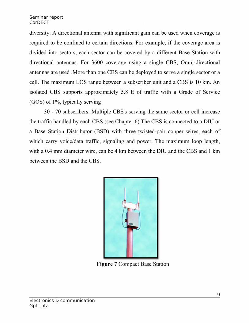
4. Compact Base Station
The Compact Base Station (CBS), shown in Figure 7, provides the radio
interface between the DIU and the corDECT subscriber terminal. It supports up to
12 simultaneous voice calls. It is a small, unobtrusive, weatherproof unit that is
remotely powered from the DIU or a BSD .The CBS has two antennas for 8
Electronics & communication Gptc.nta
Seminar report CorDECT
diversity. A directional antenna with significant gain can be used when coverage is
required to be confined to certain directions. For example, if the coverage area is
divided into sectors, each sector can be covered by a different Base Station with
directional antennas. For 3600 coverage using a single CBS, Omni-directional
antennas are used .More than one CBS can be deployed to serve a single sector or a
cell. The maximum LOS range between a subscriber unit and a CBS is 10 km. An
isolated CBS supports approximately 5.8 E of traffic with a Grade of Service
(GOS) of 1%, typically serving
30 - 70 subscribers. Multiple CBS's serving the same sector or cell increase
the traffic handled by each CBS (see Chapter 6).The CBS is connected to a DIU or
a Base Station Distributor (BSD) with three twisted-pair copper wires, each of
which carry voice/data traffic, signaling and power. The maximum loop length,
with a 0.4 mm diameter wire, can be 4 km between the DIU and the CBS and 1 km
between the BSD and the CBS.
Figure 7 Compact Base Station
9Electronics & communication Gptc.nta
Seminar report CorDECT
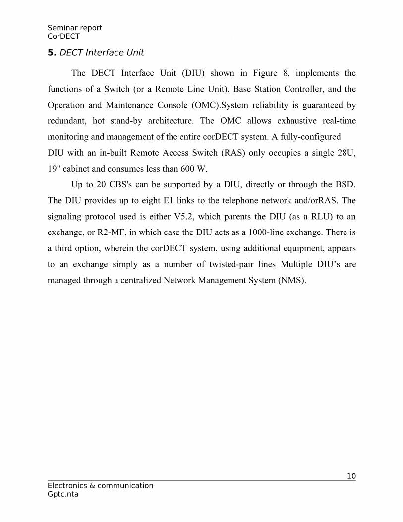
5. DECT Interface Unit
The DECT Interface Unit (DIU) shown in Figure 8, implements the
functions of a Switch (or a Remote Line Unit), Base Station Controller, and the
Operation and Maintenance Console (OMC).System reliability is guaranteed by
redundant, hot stand-by architecture. The OMC allows exhaustive real-time
monitoring and management of the entire corDECT system. A fully-configured
DIU with an in-built Remote Access Switch (RAS) only occupies a single 28U,
19" cabinet and consumes less than 600 W.
Up to 20 CBS's can be supported by a DIU, directly or through the BSD.
The DIU provides up to eight E1 links to the telephone network and/orRAS. The
signaling protocol used is either V5.2, which parents the DIU (as a RLU) to an
exchange, or R2-MF, in which case the DIU acts as a 1000-line exchange. There is
a third option, wherein the corDECT system, using additional equipment, appears
to an exchange simply as a number of twisted-pair lines Multiple DIU’s are
managed through a centralized Network Management System (NMS).
10Electronics & communication Gptc.nta
Seminar report CorDECT
Figure 8: DECT Interface Unit (DIU) with in-built RAS
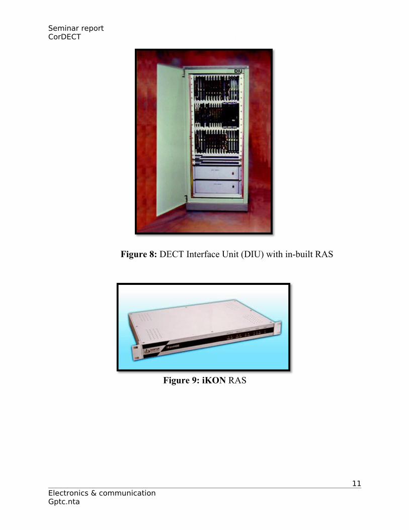
Figure 9: iKON RAS
11Electronics & communication Gptc.nta
Seminar report CorDECT
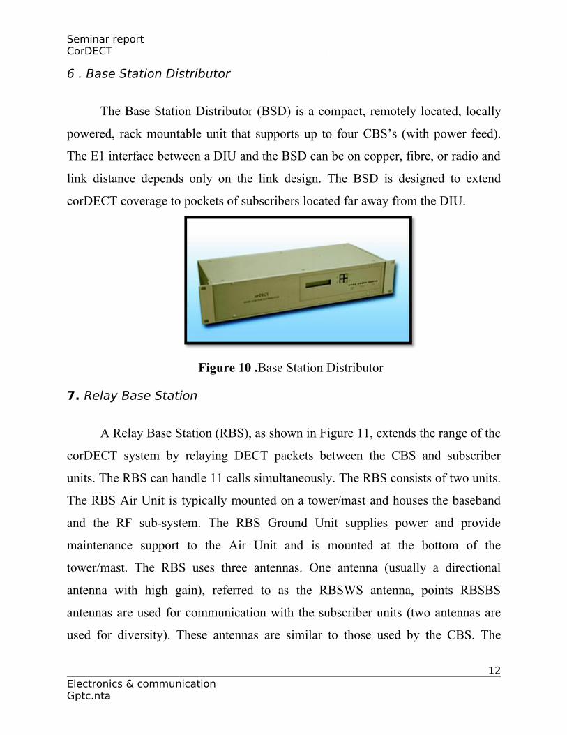
6 . Base Station Distributor
The Base Station Distributor (BSD) is a compact, remotely located, locally
powered, rack mountable unit that supports up to four CBS’s (with power feed).
The E1 interface between a DIU and the BSD can be on copper, fibre, or radio and
link distance depends only on the link design. The BSD is designed to extend
corDECT coverage to pockets of subscribers located far away from the DIU.
Figure 10 .Base Station Distributor
7. Relay Base Station
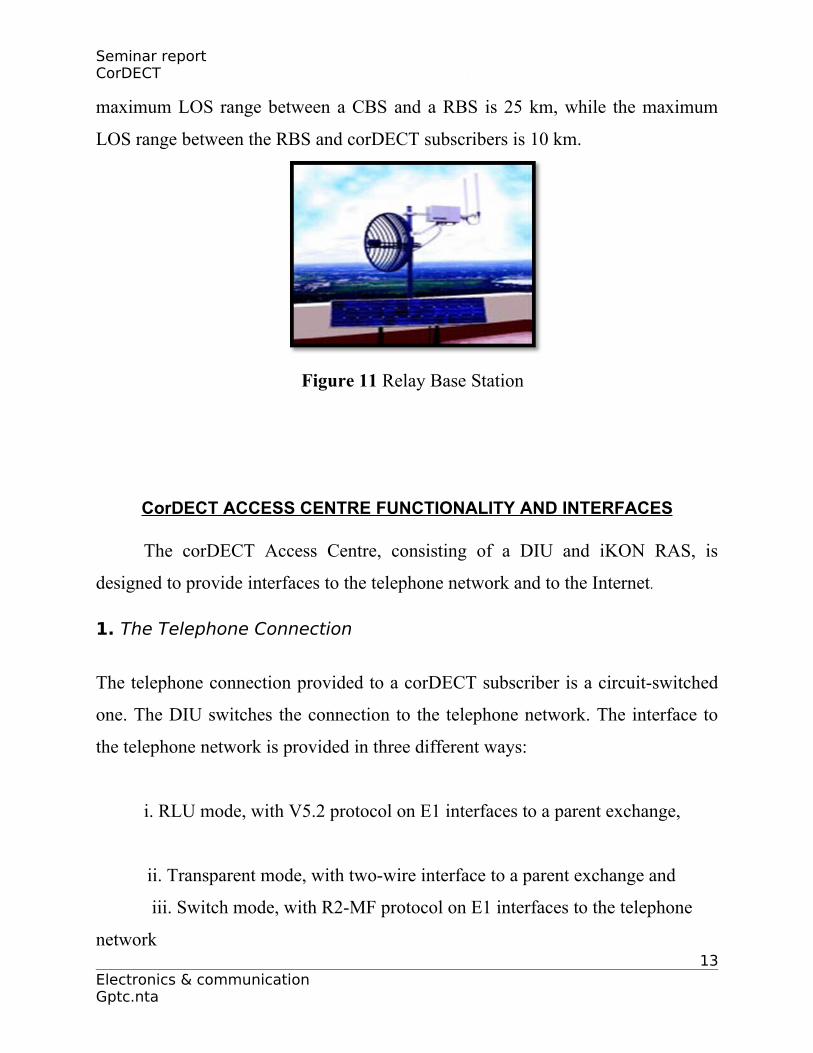
A Relay Base Station (RBS), as shown in Figure 11, extends the range of the
corDECT system by relaying DECT packets between the CBS and subscriber
units. The RBS can handle 11 calls simultaneously. The RBS consists of two units.
The RBS Air Unit is typically mounted on a tower/mast and houses the baseband
and the RF sub-system. The RBS Ground Unit supplies power and provide
maintenance support to the Air Unit and is mounted at the bottom of the
tower/mast. The RBS uses three antennas. One antenna (usually a directional
antenna with high gain), referred to as the RBSWS antenna, points RBSBS
antennas are used for communication with the subscriber units (two antennas are
used for diversity). These antennas are similar to those used by the CBS. The
12Electronics & communication Gptc.nta
Seminar report CorDECT
maximum LOS range between a CBS and a RBS is 25 km, while the maximum
LOS range between the RBS and corDECT subscribers is 10 km.
Figure 11 Relay Base Station
CorDECT ACCESS CENTRE FUNCTIONALITY AND INTERFACES
The corDECT Access Centre, consisting of a DIU and iKON RAS, is
designed to provide interfaces to the telephone network and to the Internet.
1. The Telephone Connection
The telephone connection provided to a corDECT subscriber is a circuit-switched
one. The DIU switches the connection to the telephone network. The interface to
the telephone network is provided in three different ways:
i. RLU mode, with V5.2 protocol on E1 interfaces to a parent exchange,
ii. Transparent mode, with two-wire interface to a parent exchange and
iii. Switch mode, with R2-MF protocol on E1 interfaces to the telephone
network 13
Electronics & communication Gptc.nta
Seminar report CorDECT
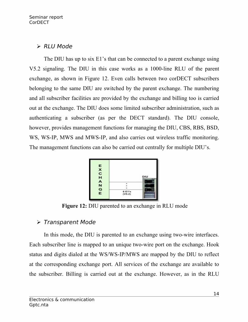
RLU Mode
The DIU has up to six E1’s that can be connected to a parent exchange using
V5.2 signaling. The DIU in this case works as a 1000-line RLU of the parent
exchange, as shown in Figure 12. Even calls between two corDECT subscribers
belonging to the same DIU are switched by the parent exchange. The numbering
and all subscriber facilities are provided by the exchange and billing too is carried
out at the exchange. The DIU does some limited subscriber administration, such as
authenticating a subscriber (as per the DECT standard). The DIU console,
however, provides management functions for managing the DIU, CBS, RBS, BSD,
WS, WS-IP, MWS and MWS-IP, and also carries out wireless traffic monitoring.
The management functions can also be carried out centrally for multiple DIU’s.
Figure 12: DIU parented to an exchange in RLU mode
Transparent Mode
In this mode, the DIU is parented to an exchange using two-wire interfaces.
Each subscriber line is mapped to an unique two-wire port on the exchange. Hook
status and digits dialed at the WS/WS-IP/MWS are mapped by the DIU to reflect
at the corresponding exchange port. All services of the exchange are available to
the subscriber. Billing is carried out at the exchange. However, as in the RLU
14Electronics & communication Gptc.nta
Seminar report CorDECT
mode the DIU carries out subscriber authentication and system management
functions.
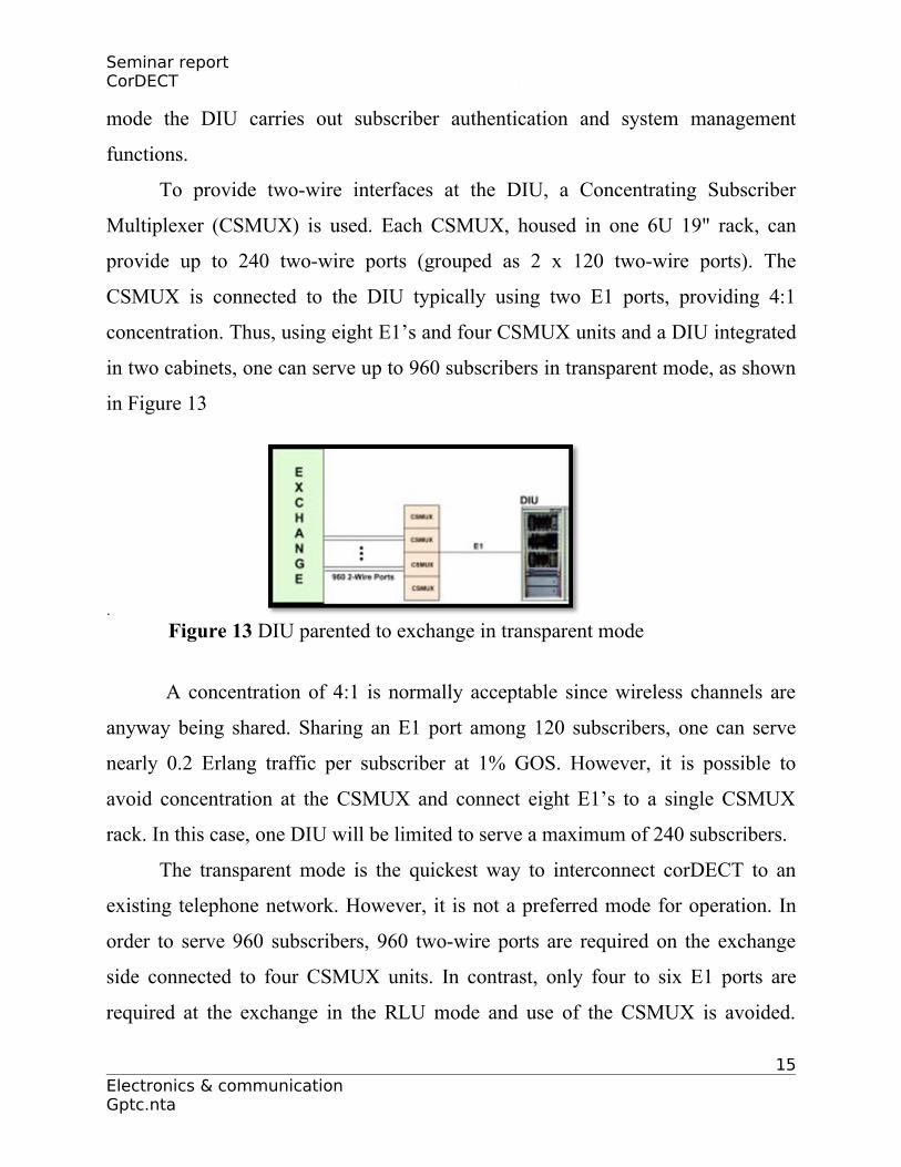
To provide two-wire interfaces at the DIU, a Concentrating Subscriber
Multiplexer (CSMUX) is used. Each CSMUX, housed in one 6U 19" rack, can
provide up to 240 two-wire ports (grouped as 2 x 120 two-wire ports). The
CSMUX is connected to the DIU typically using two E1 ports, providing 4:1
concentration. Thus, using eight E1’s and four CSMUX units and a DIU integrated
in two cabinets, one can serve up to 960 subscribers in transparent mode, as shown
in Figure 13
.
Figure 13 DIU parented to exchange in transparent mode
A concentration of 4:1 is normally acceptable since wireless channels are
anyway being shared. Sharing an E1 port among 120 subscribers, one can serve
nearly 0.2 Erlang traffic per subscriber at 1% GOS. However, it is possible to
avoid concentration at the CSMUX and connect eight E1’s to a single CSMUX
rack. In this case, one DIU will be limited to serve a maximum of 240 subscribers.
The transparent mode is the quickest way to interconnect corDECT to an
existing telephone network. However, it is not a preferred mode for operation. In
order to serve 960 subscribers, 960 two-wire ports are required on the exchange
side connected to four CSMUX units. In contrast, only four to six E1 ports are
required at the exchange in the RLU mode and use of the CSMUX is avoided.
15Electronics & communication Gptc.nta
Seminar report CorDECT
Thus, in the RLU mode, the size of the exchange as well as the DIU is much
smaller and the power required is also less when compared to the transparent
mode. A more serious problem in the transparent mode comes from a signaling
anomaly that can emerge in some specific situations. For example, when an
incoming call comes to the exchange for a subscriber, the exchange signals ring-
back to the calling subscriber if it finds from its database that the called subscriber
is free. The exchange simultaneously feeds ring to the corresponding two-wire
port. This is detected by the CSMUX in the DIU and the DIU then attempts to page
the corresponding WS/WS-IP and ring the subscriber. However as wireless
channels are shared, it is possible that sometimes the DIU finds no free channel
and fails to feed ring to the subscriber. The anomaly develops when the called port
gets ring-back tone, but the called party does not get a ring. Such a situation can
sometimes become problematic. The transparent mode is therefore not the most
desirable mode of operation. Nevertheless, it is the quickest way to integrate a
wireless system to the existing telephone network anywhere in the world.
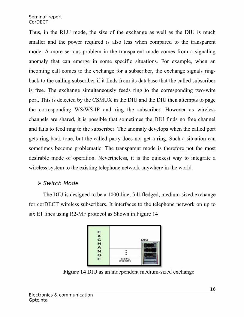
Switch Mode
The DIU is designed to be a 1000-line, full-fledged, medium-sized exchange
for corDECT wireless subscribers. It interfaces to the telephone network on up to
six E1 lines using R2-MF protocol as Shown in Figure 14
Figure 14 DIU as an independent medium-sized exchange
16Electronics & communication Gptc.nta

Seminar report CorDECT
All the exchange functions, including subscriber administration, billing, and
management, are carried out at the DIU itself. The advantage of this mode is that
the cost of an exchange is totally saved. The DIU can also serve as a Direct In-
Dialing (DID) PB
2. Internet Connection
A corDECT subscriber connects to the WS-IP using a PPP dial-up
connection on the RS-232 port. The port is programmed at 38.4 kbps rate for a 35
kbps Internet connection and at 115.2 kbps rate for a 70 kbps Internet connection.
The PC connected to the RS-232 port on the WS-IP dials a pre-designated number
using a standard dialup routine. The DIU sets up a circuit-switched connection
between the WS-IP and the iKON RAS connected to the DIU on an E1 port.
The Internet connection employs the wireless link between the WS-IP and
the CBS and the wired links between the CBS and the DIU and between the DIU
and the RAS. Since the BER on the wireless link could occasionally be high, the
PPP packet is fragmented and transmitted with an error detection code on the link
from the WS-IP to the DIU. ARQ is performed on this link to obtain error-free
fragment transmission. The PPP packets are re-assembled from these fragments
before transmitting it to the PC (on the WS-IP side) and to the RAS (on the DIU
side).
The connection between the WS-IP and the DIU is at 32 kbps or 64 kbps
(using one or two DECT slots on air). The start/stop bits received at the RS-232
port are stripped before transmission on air. This enables 35 kbps Internet
throughput between the user PC and the RAS on the 32 kbps connection in an
error-free situation. Similarly, 70 kbps Internet throughput is possible between the
17Electronics & communication Gptc.nta
Seminar report CorDECT
user PC and the RAS on the 64 kbps connection. Bit errors on the link will
temporarily bring down the throughput.
Each RAS has two E1 ports for connecting to the DIU and thus can support
Internet connections for up to 60 subscribers at a time. The PPP connections are
terminated at the RAS and IP packets are routed to the Ethernet port of the RAS
for onward transmission to the Internet. The Ethernet ports from multiple RAS’s
would normally be connected to an Ethernet switch. The Ethernet switch in turn
would be connected to an Internet router, completing the connection to the
Internet.
CorDECT DEVELOPMENT EXAMPLES
We saw that the corDECT DIU can be deployed as an access system,
parented to an exchange using either the V5.2 access protocol, or transparently
using two-wire Interfaces. Alternatively, the corDECT DIU itself can act as a
Local Exchange (LE), or even as a direct-in-dialing PBX.. Here presents a few
deployment scenarios for the corDECT Wireless Access System.
CorDECT Deployment with DIU in Exchange Premises
In one of the most widely deployed scenarios, the corDECT DIU is placed in
the local exchange premises, parented to an exchange in a transparent manner or
using the V5.2 protocol, or as an independent Local Exchange. This scenario will
be widely used by an incumbent operator with existing infrastructure. The
exchange building (usually one of the taller buildings in the area) would have a
tower to deploy Compact Base Stations as shown in Figure 4.1
18Electronics & communication Gptc.nta
Seminar report CorDECT
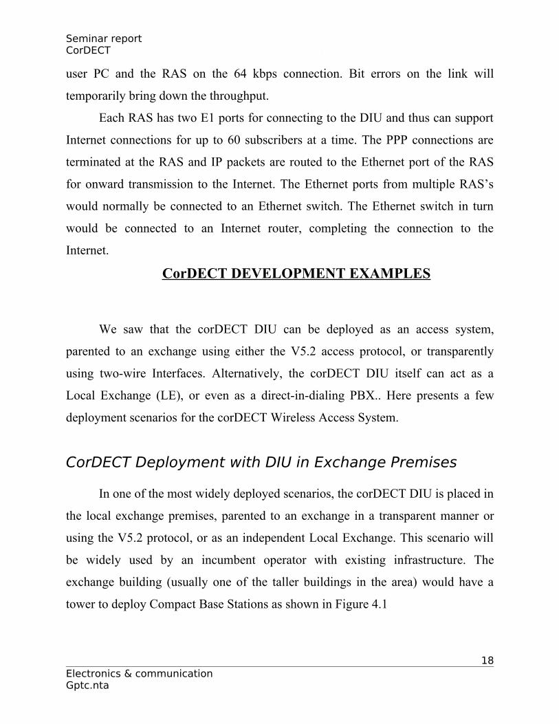
Figure 4.1 DIU in exchange premises with co-located CBS
The tower could be a short 15 m rooftop mast, but in some cases, could be a
self-supporting 25 - 35 m tower on the ground. Multiple CBS’s could be mounted
on this tower using Omni directional antennas, but more often, using directional
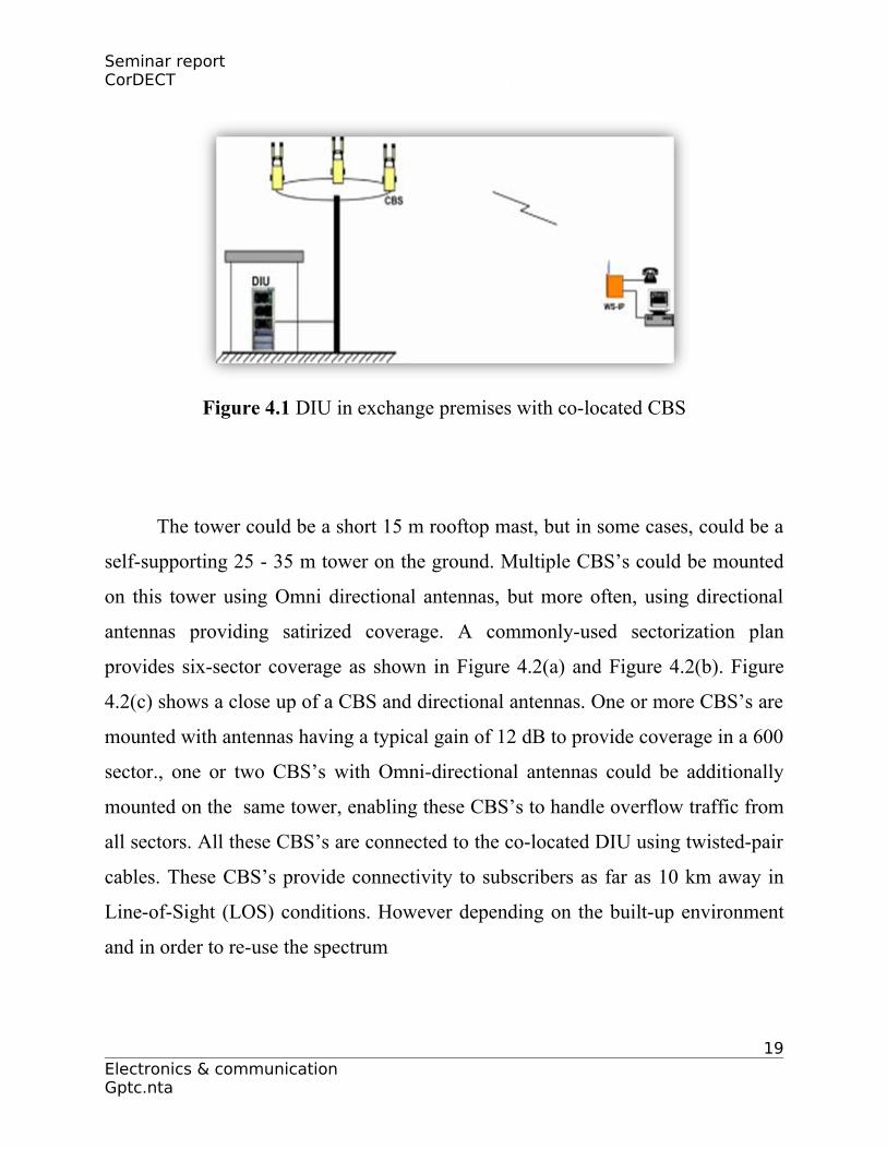
antennas providing satirized coverage. A commonly-used sectorization plan
provides six-sector coverage as shown in Figure 4.2(a) and Figure 4.2(b). Figure
4.2(c) shows a close up of a CBS and directional antennas. One or more CBS’s are
mounted with antennas having a typical gain of 12 dB to provide coverage in a 600
sector., one or two CBS’s with Omni-directional antennas could be additionally
mounted on the same tower, enabling these CBS’s to handle overflow traffic from
all sectors. All these CBS’s are connected to the co-located DIU using twisted-pair
cables. These CBS’s provide connectivity to subscribers as far as 10 km away in
Line-of-Sight (LOS) conditions. However depending on the built-up environment
and in order to re-use the spectrum
19Electronics & communication Gptc.nta
Seminar report CorDECT
(a)
(b) (c)
Figure 4.2 Six sector coverage by CBS
Remote Location of CBS
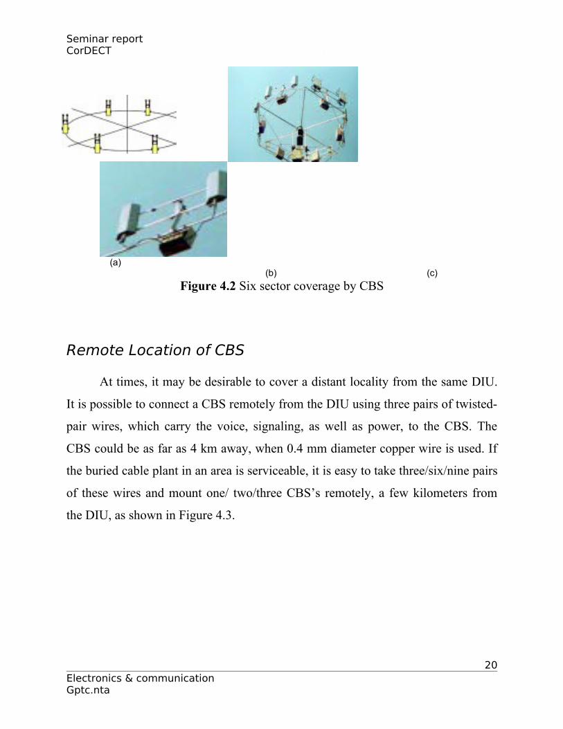
At times, it may be desirable to cover a distant locality from the same DIU.
It is possible to connect a CBS remotely from the DIU using three pairs of twisted-
pair wires, which carry the voice, signaling, as well as power, to the CBS. The
CBS could be as far as 4 km away, when 0.4 mm diameter copper wire is used. If
the buried cable plant in an area is serviceable, it is easy to take three/six/nine pairs
of these wires and mount one/ two/three CBS’s remotely, a few kilometers from
the DIU, as shown in Figure 4.3.
20Electronics & communication Gptc.nta
Seminar report CorDECT
Figure 4.3 Remote CBS connected using copper twisted-pair wire
The CBS’s could then be mounted on a tall building using a 3 - 6 m pole on
the roof and provide coverage to 30 - 150 subscribers in the neighborhood of this
remote location. It is important, however, that the buried cable plant be in
reasonable shape and not fail during rain, if this option is to be used.
A more appropriate way of connecting a multi- CBS cluster remotely is to
use the Base Station Distributor (BSD). A BSD is connected to the DIU by a
standard E1 link, using an optical fibre, point-to-point microwave radio, or even
copper (for example, using HDSL). The BSD with a small 48 V power supply unit
could then be placed in a remote building (say, under a staircase landing) where an
optical fibre connection or a cable link with HDSL, is available. Up to four CBS’s
can now be connected to the BSD and mounted on a pole or small tower as shown
in Figure 4.4. These CBS’s could provide coverage to almost 200 subscribers in
the vicinity.
Alternatively, the tower could also support the antenna for a digital
microwave point-to-point E1
21Electronics & communication Gptc.nta
Seminar report CorDECT
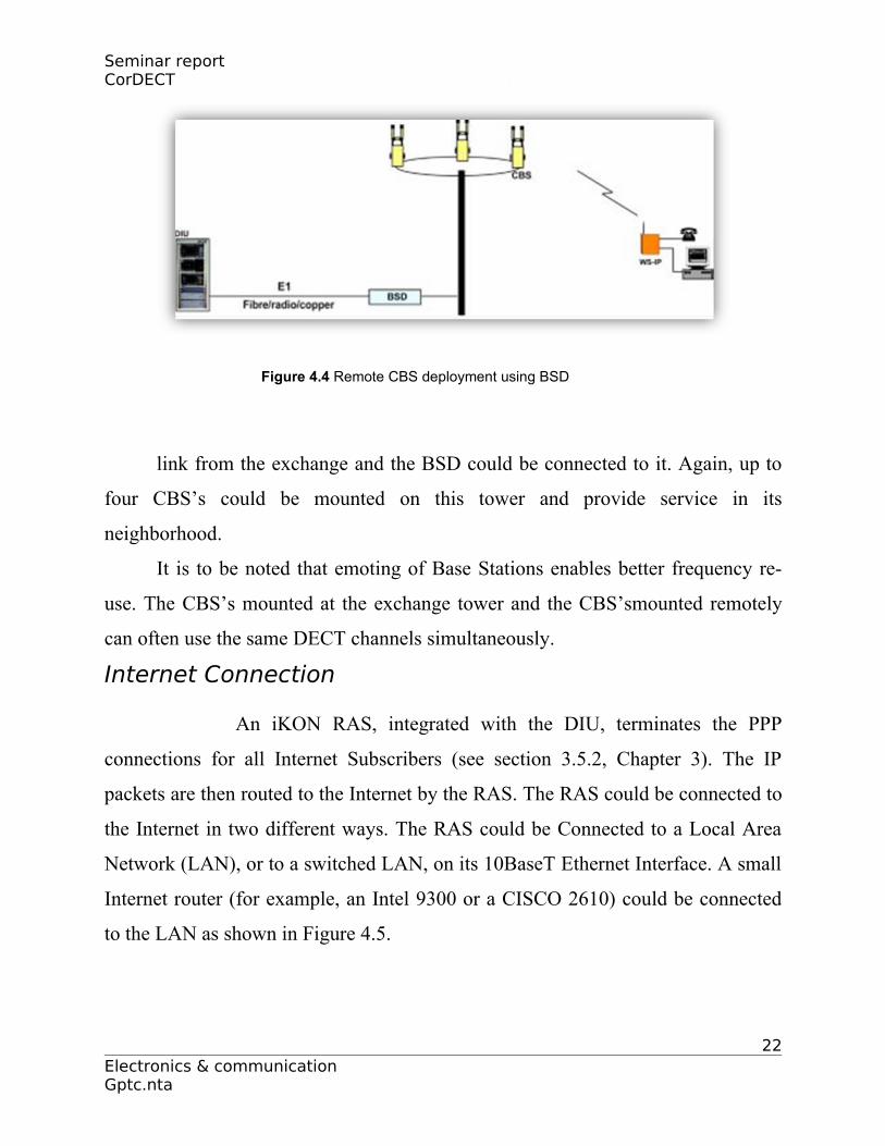
Figure 4.4 Remote CBS deployment using BSD
link from the exchange and the BSD could be connected to it. Again, up to
four CBS’s could be mounted on this tower and provide service in its
neighborhood.
It is to be noted that emoting of Base Stations enables better frequency re-
use. The CBS’s mounted at the exchange tower and the CBS’smounted remotely
can often use the same DECT channels simultaneously.
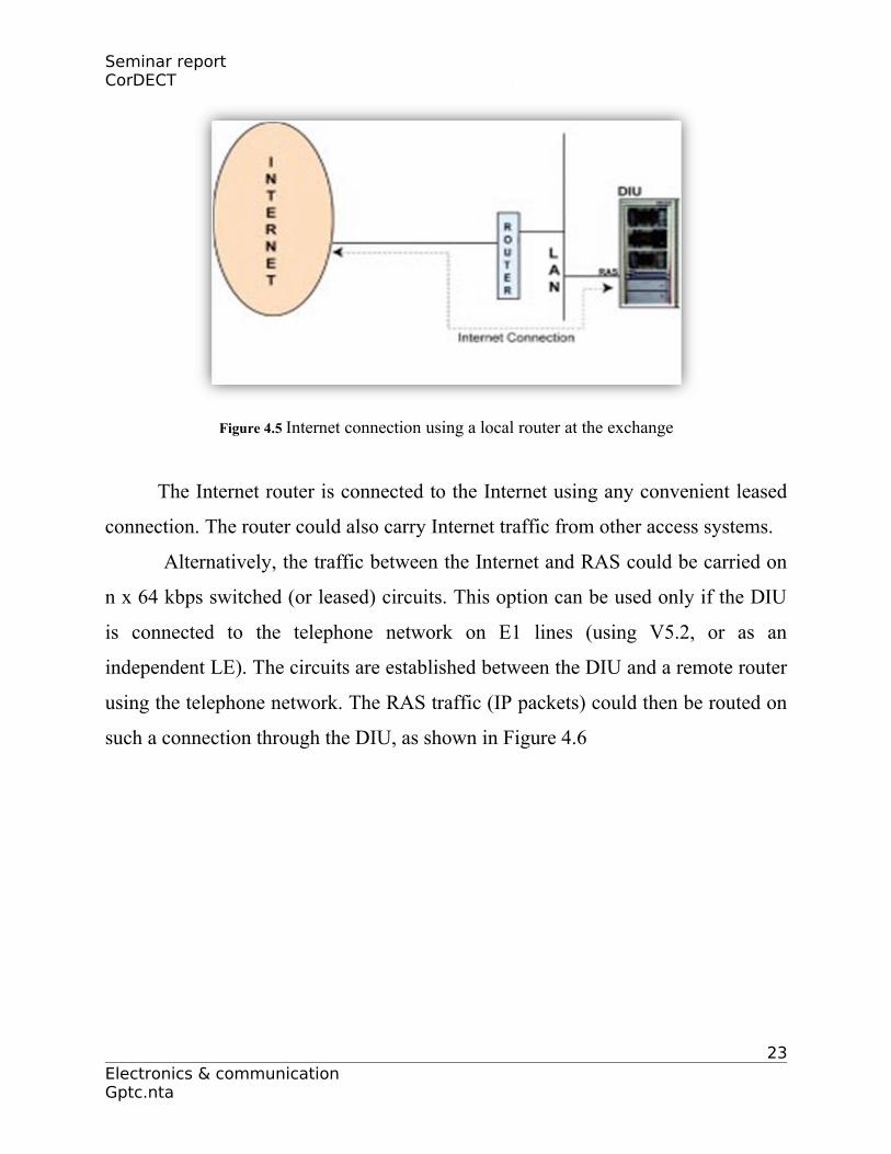
Internet Connection
An iKON RAS, integrated with the DIU, terminates the PPP
connections for all Internet Subscribers (see section 3.5.2, Chapter 3). The IP
packets are then routed to the Internet by the RAS. The RAS could be connected to
the Internet in two different ways. The RAS could be Connected to a Local Area
Network (LAN), or to a switched LAN, on its 10BaseT Ethernet Interface. A small
Internet router (for example, an Intel 9300 or a CISCO 2610) could be connected
to the LAN as shown in Figure 4.5.
22Electronics & communication Gptc.nta
Seminar report CorDECT
Figure 4.5 Internet connection using a local router at the exchange
The Internet router is connected to the Internet using any convenient leased
connection. The router could also carry Internet traffic from other access systems.
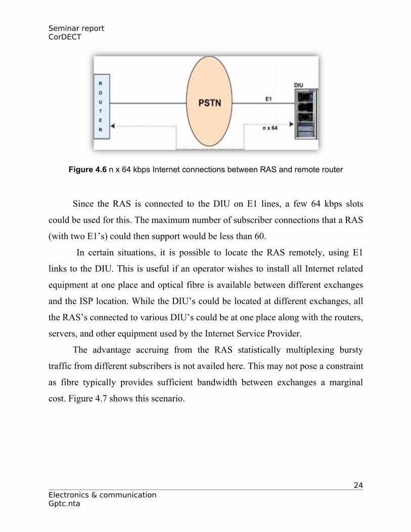
Alternatively, the traffic between the Internet and RAS could be carried on
n x 64 kbps switched (or leased) circuits. This option can be used only if the DIU
is connected to the telephone network on E1 lines (using V5.2, or as an
independent LE). The circuits are established between the DIU and a remote router
using the telephone network. The RAS traffic (IP packets) could then be routed on
such a connection through the DIU, as shown in Figure 4.6
23Electronics & communication Gptc.nta
Seminar report CorDECT
Figure 4.6 n x 64 kbps Internet connections between RAS and remote router
Since the RAS is connected to the DIU on E1 lines, a few 64 kbps slots
could be used for this. The maximum number of subscriber connections that a RAS
(with two E1’s) could then support would be less than 60.
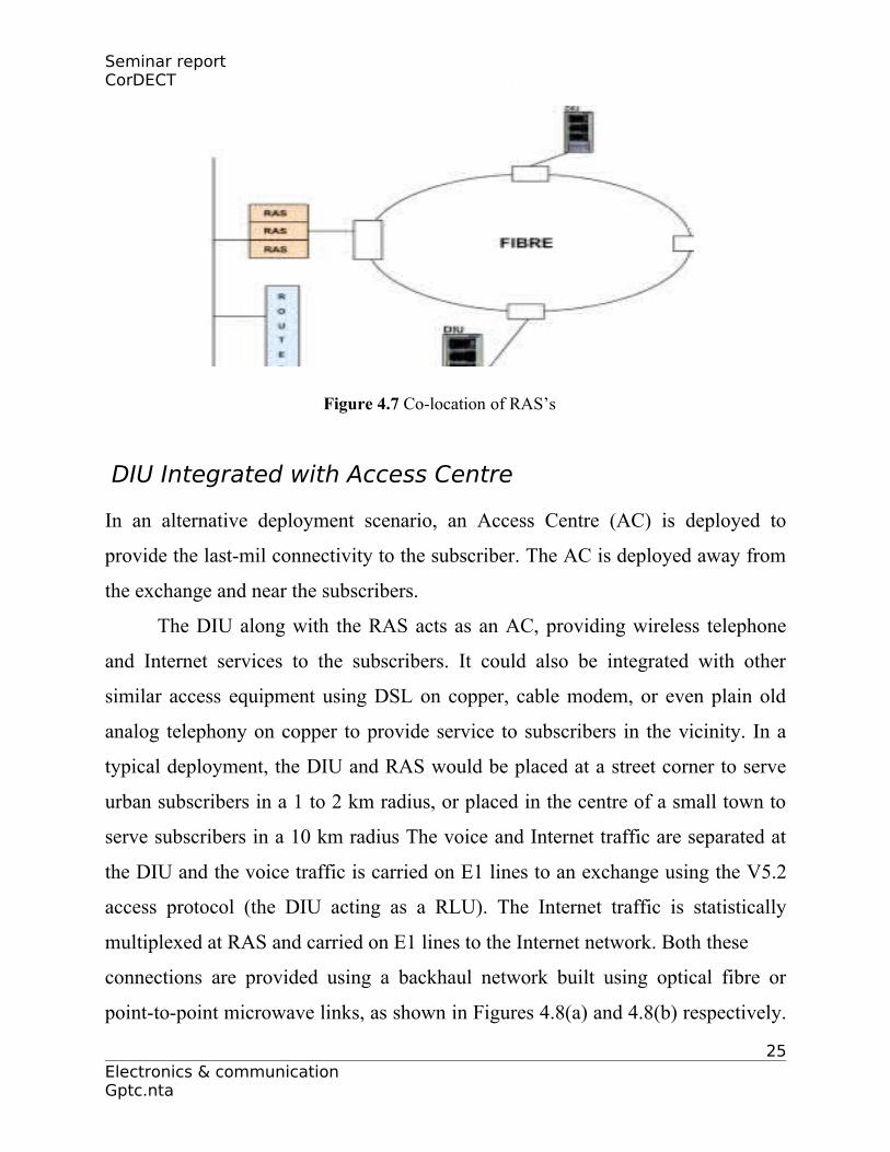
In certain situations, it is possible to locate the RAS remotely, using E1
links to the DIU. This is useful if an operator wishes to install all Internet related
equipment at one place and optical fibre is available between different exchanges
and the ISP location. While the DIU’s could be located at different exchanges, all
the RAS’s connected to various DIU’s could be at one place along with the routers,
servers, and other equipment used by the Internet Service Provider.
The advantage accruing from the RAS statistically multiplexing bursty
traffic from different subscribers is not availed here. This may not pose a constraint
as fibre typically provides sufficient bandwidth between exchanges a marginal
cost. Figure 4.7 shows this scenario.
24Electronics & communication Gptc.nta
Seminar report CorDECT
Figure 4.7 Co-location of RAS’s
DIU Integrated with Access Centre
In an alternative deployment scenario, an Access Centre (AC) is deployed to
provide the last-mil connectivity to the subscriber. The AC is deployed away from
the exchange and near the subscribers.
The DIU along with the RAS acts as an AC, providing wireless telephone
and Internet services to the subscribers. It could also be integrated with other
similar access equipment using DSL on copper, cable modem, or even plain old
analog telephony on copper to provide service to subscribers in the vicinity. In a
typical deployment, the DIU and RAS would be placed at a street corner to serve
urban subscribers in a 1 to 2 km radius, or placed in the centre of a small town to
serve subscribers in a 10 km radius The voice and Internet traffic are separated at
the DIU and the voice traffic is carried on E1 lines to an exchange using the V5.2
access protocol (the DIU acting as a RLU). The Internet traffic is statistically
multiplexed at RAS and carried on E1 lines to the Internet network. Both these
connections are provided using a backhaul network built using optical fibre or
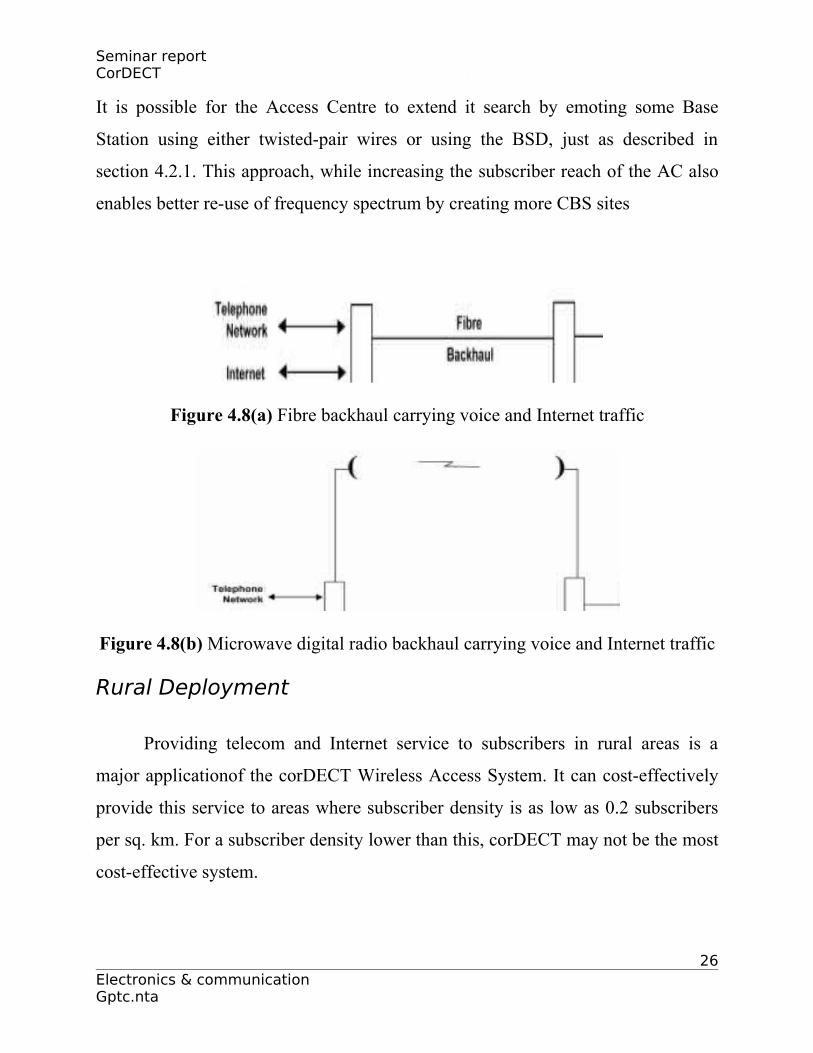
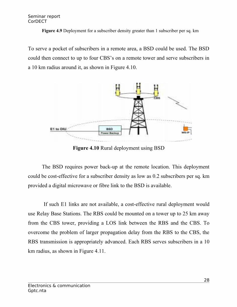
point-to-point microwave links, as shown in Figures 4.8(a) and 4.8(b) respectively.
25Electronics & communication Gptc.nta
Seminar report CorDECT
It is possible for the Access Centre to extend it search by emoting some Base
Station using either twisted-pair wires or using the BSD, just as described in
section 4.2.1. This approach, while increasing the subscriber reach of the AC also
enables better re-use of frequency spectrum by creating more CBS sites
Figure 4.8(a) Fibre backhaul carrying voice and Internet traffic
Figure 4.8(b) Microwave digital radio backhaul carrying voice and Internet traffic
Rural Deployment
Providing telecom and Internet service to subscribers in rural areas is a
major applicationof the corDECT Wireless Access System. It can cost-effectively
provide this service to areas where subscriber density is as low as 0.2 subscribers
per sq. km. For a subscriber density lower than this, corDECT may not be the most
cost-effective system.
26Electronics & communication Gptc.nta

Seminar report CorDECT
Line-of-Sight (LOS) between a subscriber antenna and Base Station/Relay
Base Station is necessary for the corDECT system to provide service to subscribers
in sparse (low subscriber density) areas. It is therefore necessary to choose sites for
CBS and RBS towers carefully, so that subscribers in a 10 km radius can be
provided service. Similarly, antennas have to be mounted at subscriber premises
using poles, so that LOS to the CBS/RBS is available. The availability of light and
compact antennas for the Wallset makes this task a little easier.
Further, subscribers in rural areas may not have reliable power and solar
panels may have to be used. A compact solar panel can be connected to the WS or
WS-IP to power the unit and charge the built-in battery, with solar power taking
over when the main is off/low.
A DIU along with a RAS could be located either in a rural exchange
building or a RLU building, adjacent to a tower (typically 15 m to 35 m high).
CBS’s mounted on the tower can directly serve rural subscribers in a 10 km radius
(or 300 sq. km area), as shown in Figure 4.9. This deployment scenario is adequate
for a subscriber density higher than 1 subscriber per sq. km.
27Electronics & communication Gptc.nta
Seminar report CorDECT
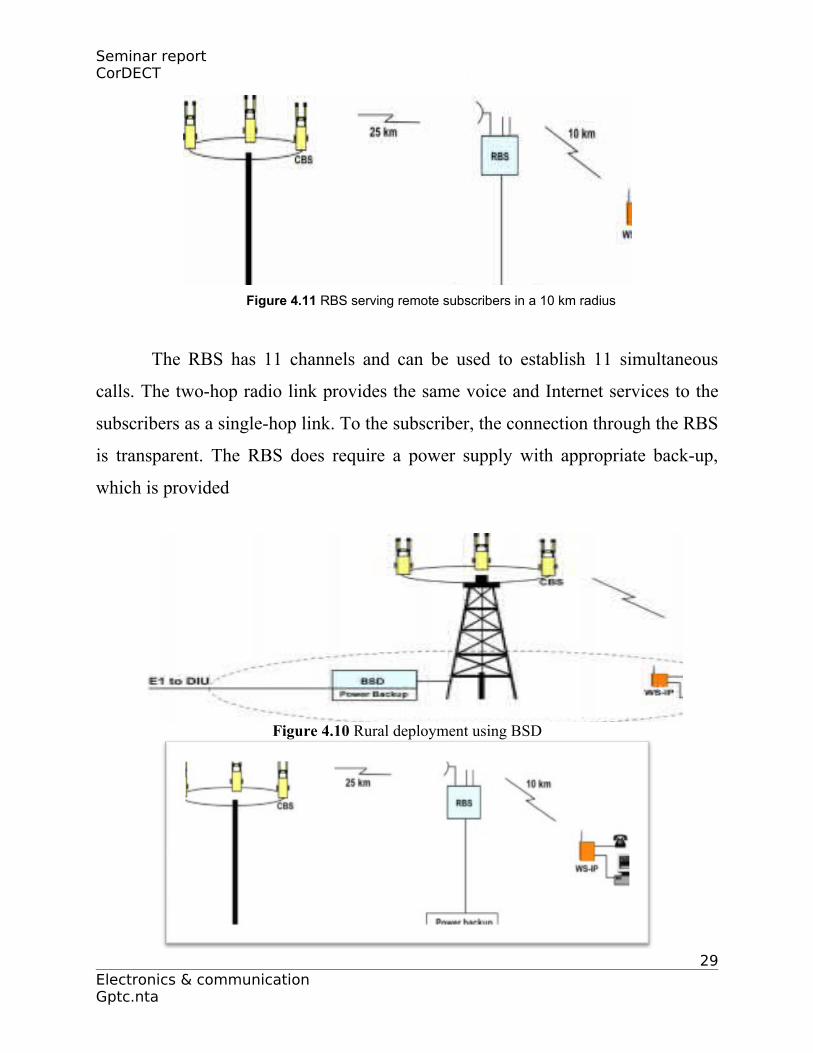
Figure 4.9 Deployment for a subscriber density greater than 1 subscriber per sq. km
To serve a pocket of subscribers in a remote area, a BSD could be used. The BSD
could then connect to up to four CBS’s on a remote tower and serve subscribers in
a 10 km radius around it, as shown in Figure 4.10.
Figure 4.10 Rural deployment using BSD
The BSD requires power back-up at the remote location. This deployment
could be cost-effective for a subscriber density as low as 0.2 subscribers per sq. km
provided a digital microwave or fibre link to the BSD is available.
If such E1 links are not available, a cost-effective rural deployment would
use Relay Base Stations. The RBS could be mounted on a tower up to 25 km away
from the CBS tower, providing a LOS link between the RBS and the CBS. To
overcome the problem of larger propagation delay from the RBS to the CBS, the
RBS transmission is appropriately advanced. Each RBS serves subscribers in a 10
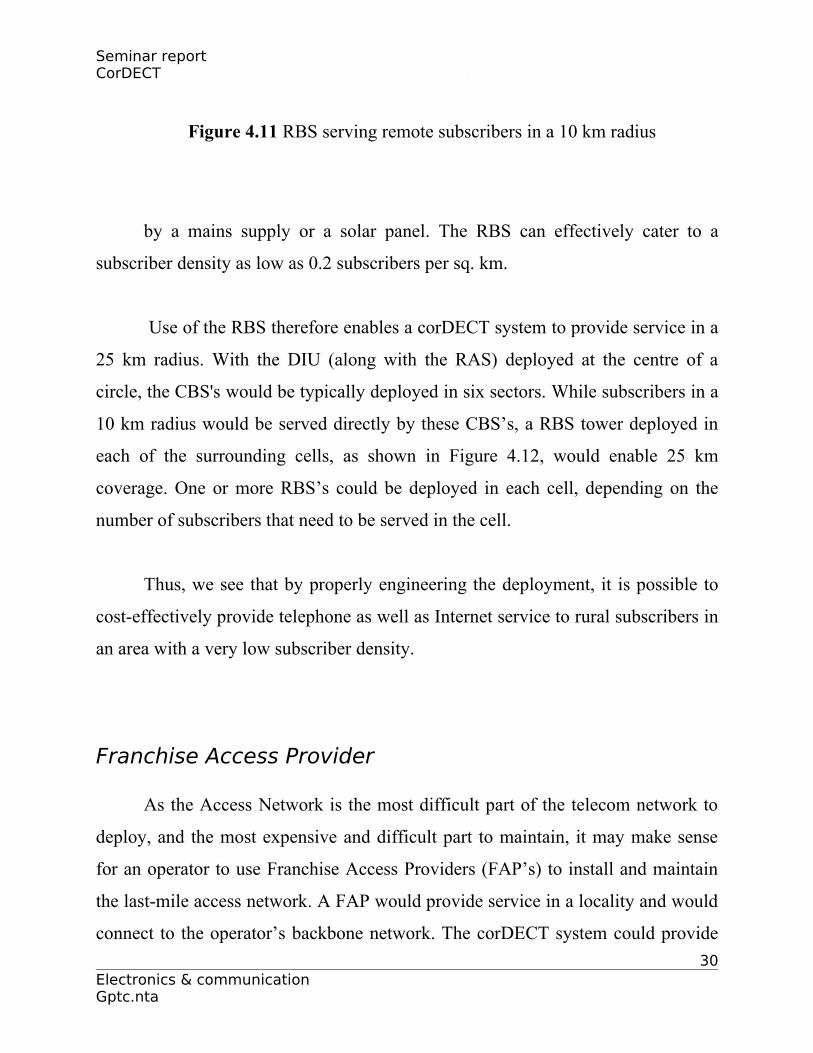
km radius, as shown in Figure 4.11.
28Electronics & communication Gptc.nta
Seminar report CorDECT
Figure 4.11 RBS serving remote subscribers in a 10 km radius
The RBS has 11 channels and can be used to establish 11 simultaneous
calls. The two-hop radio link provides the same voice and Internet services to the
subscribers as a single-hop link. To the subscriber, the connection through the RBS
is transparent. The RBS does require a power supply with appropriate back-up,
which is provided
Figure 4.10 Rural deployment using BSD
29Electronics & communication Gptc.nta
Seminar report CorDECT
Figure 4.11 RBS serving remote subscribers in a 10 km radius
by a mains supply or a solar panel. The RBS can effectively cater to a
subscriber density as low as 0.2 subscribers per sq. km.
Use of the RBS therefore enables a corDECT system to provide service in a
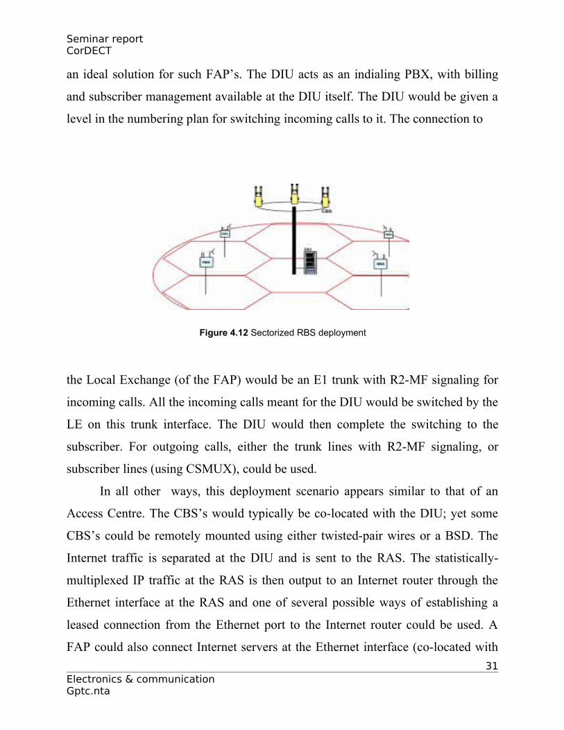
25 km radius. With the DIU (along with the RAS) deployed at the centre of a
circle, the CBS's would be typically deployed in six sectors. While subscribers in a
10 km radius would be served directly by these CBS’s, a RBS tower deployed in
each of the surrounding cells, as shown in Figure 4.12, would enable 25 km
coverage. One or more RBS’s could be deployed in each cell, depending on the
number of subscribers that need to be served in the cell.
Thus, we see that by properly engineering the deployment, it is possible to
cost-effectively provide telephone as well as Internet service to rural subscribers in
an area with a very low subscriber density.
Franchise Access Provider
As the Access Network is the most difficult part of the telecom network to
deploy, and the most expensive and difficult part to maintain, it may make sense
for an operator to use Franchise Access Providers (FAP’s) to install and maintain
the last-mile access network. A FAP would provide service in a locality and would
connect to the operator’s backbone network. The corDECT system could provide
30Electronics & communication Gptc.nta
Seminar report CorDECT
an ideal solution for such FAP’s. The DIU acts as an indialing PBX, with billing
and subscriber management available at the DIU itself. The DIU would be given a
level in the numbering plan for switching incoming calls to it. The connection to
Figure 4.12 Sectorized RBS deployment
the Local Exchange (of the FAP) would be an E1 trunk with R2-MF signaling for
incoming calls. All the incoming calls meant for the DIU would be switched by the
LE on this trunk interface. The DIU would then complete the switching to the
subscriber. For outgoing calls, either the trunk lines with R2-MF signaling, or
subscriber lines (using CSMUX), could be used.
In all other ways, this deployment scenario appears similar to that of an
Access Centre. The CBS’s would typically be co-located with the DIU; yet some
CBS’s could be remotely mounted using either twisted-pair wires or a BSD. The
Internet traffic is separated at the DIU and is sent to the RAS. The statistically-
multiplexed IP traffic at the RAS is then output to an Internet router through the
Ethernet interface at the RAS and one of several possible ways of establishing a
leased connection from the Ethernet port to the Internet router could be used. A
FAP could also connect Internet servers at the Ethernet interface (co-located with
31Electronics & communication Gptc.nta
Seminar report CorDECT
the RAS and DIU) and provide services such as mail server, web-server, etc. It is
also possible to co-locate a RADIUS server, used for Internet billing and
accounting, at the same place.
CorDECT FEATURES AT A GLANCE
The corDECT WLL system provides features and services comparable to the
best wire line systems. In the Switch (Local Exchange) mode, it boasts of all the
features of a large digital exchange. The Wallset IP provides simultaneous voice
and Internet access (like an ISDN line) as a basic feature that all subscribers can
have. Base Stations can be deployed in a multitude of ways, some suited to an
incumbent operator, some to a green field operator, and others that enable coverage
of sparsely populated rural areas. The system also has sophisticated Operation and
Maintenance support and a Network Management System for managing a
corDECT network. The next few sections describe some key features of the
corDECT system.
Voice Quality:
corDECT delivers the same toll-quality speech performance as a good
copper-based local loop. Toll-quality voice is ensured by using 32 kbps ADPCM
for voice digitization as per the ITU-T G.726 standard. ADPCM also ensures
transparency to DTMF signals for Interactive Voice Response Systems.
Data Services:
32Electronics & communication Gptc.nta
Seminar report CorDECT
The employment of 32 kbps ADPCM permits all voice-band data services
available from a conventional wired connection. It is also possible to occupy a
double time slot on air to transmit at 64 kbps with error correction. This can be
used for data connectivity at speeds similar to the best wire line speed. The speed
of a modem/G3 fax supported using 32 kbps ADPCM is 9600 bps, but with a
double slot connection V.34 and V.90 modems can operate at full speed.
Internet Access Speed:
Internet access is possible simultaneously with a voice call using the Wallset
IP. There are two access rates: 35 kbps and 70 kbps, using one and two time slots
respectively.
Payphone/PCO:
The system supports payphone with battery reversal as well as 12 kHz/16
kHz metering pulses. The pulses are provided by the Wallset for an external charge
meter. The system also supports a CCB payphone (battery reversal only).
System Capacity:
Each corDECT system supports up to 1000 subscribers. Its Base Stations can
evacuate more than 150 E of traffic and funnel it to the telephone network and
Internet using up to eight E1 links.
Air Interface Transmit Power:
33Electronics & communication Gptc.nta
Seminar report CorDECT
The power transmitted by a Wallset or Base Station nominally is 250 mW during
the burst, or about 10 mW on the average. These ties in with the need for small
cells to enhance frequency re-use and also conserve battery power.
Typical CBS Coverage:
The coverage achieved by corDECT is 10 km in Line-of-Sight (LOS)
conditions, made possible by enhanced receiver sensitivity, a patented timing
adjustment feature and compact high gain antennas. The non-LOS (NLOS)
coverage varies from 400 m to 1 km depending on the way the CBS’s are installed.
Typical RBS Coverage:
The Relay Base Station (RBS) can be at a maximum distance of 25 km from
the CBS and it can serve subscribers in a 10 km radius around it. The RBS is
primarily meant to be used in rural or sparsely populated areas. It also finds
occasional use in urban areas for covering regions in shadow.
Authentication and Subscription
Authentication is the process by which a corDECT subscriber terminal is
positively verified as belonging to a legitimate subscriber of a particular DIU. It is
invoked during call setup for every call. It can also be invoked during other
circumstances like termination of access of a Wallset by the DIU.
Authentication involves an Authentication Key which is never transmitted
on air. The keys are maintained securely in the system and are inaccessible to
anyone. Subscription is the process by which a subscriber is added/deleted from
34Electronics & communication Gptc.nta
Seminar report CorDECT
the system and the features the subscriber desires to have are enabled. It is also the
process by which the system formally transfers the identity, such as subscriber
number, to the Wallset. The DECT standard specifies the usage of “On-Air Access
Rights” procedures for the Wallset to obtain access rights to the system. The
Wallset can use this to:
(i) gain access to the system and make calls and
(ii) recognize the system in order to receive calls.
The DIU can use this to:
(i) validate service requests from Wallset,
(ii) limit access to classes of service, and
(iii) recognize calls for valid Wallsets in order to route calls to them.
Major Subscriber Services:
The corDECT system when operating in Switch mode provides all the
services of a large modern exchange. All the features and services specified by
major telecom administrations (like the Indian Department of
Telecommunications) in their Large Exchange Specifications are supported. Some
of the important services are:
35Electronics & communication Gptc.nta
Seminar report CorDECT
• Standing Alarm Call Service
• Occasional Alarm Call Service
• Call Completion Supplementary Services
Absent subscriber
Do not disturb subscriber
Call waiting
Dual telephone number
• Call Offering Supplementary Services
Call diversion on no reply
Call diversion on busy
Call diversion unconditional
• Call Restriction Supplementary Services
Outgoing only lines
Incoming only lines
Outgoing call restriction service
• Charging and Charge Debiting Supplementary Services
Subscriber call charge meter
Subscriber bulk meter
Non metered lines
Automatic transferred charge call (collect call)
• Three-Party Conference Calling
Billing for conference call
• Rapid Call-Setup Supplementary Services
• Abbreviated dialing• Fixed destination call on time-out
36Electronics & communication Gptc.nta
Seminar report CorDECT
• Non-Supplementary Services
Payphone service
Malicious call identification
Ring-back facility
Interception of calls
Priority lines
CLI and CLI restriction
Major Switch Features: The corDECT system when operating as a Local Exchange provides the
operator extensive numbering, routing, traffic monitoring, and testing facilities.
The major features :
• Exchange Code Numbering Plan
• Digit Analysis – Access Check
• Digit Analysis – RoutingDigit Analysis – Charging
• Operator Trunk Offer
• Temporary Out-of-Service Subscriber
• Hunting for a Group of Subscribers
• Subscriber Line Supervision
• Speech monitoring by intelligence agency
• PSTN line supervision
• Total exchange meter and junction metering
• Measuring subscriber supplementary service utilization
• Measuring BHCA (regular measurement)
• Measuring traffic for a period (occasional measurement)
37Electronics & communication Gptc.nta
Seminar report CorDECT
• Measuring call attempts (regular and occasional)
• Logs for congestion
• Periodic testing of subscribers
• Periodic testing of junctions
• Facility for multiple printers
• Facility to execute commands from calendar
• Copy switching in hot standby mode
OMC Features:
The corDECT system’s Operation and Maintenance Console supports the
following:
System Administration Features:
• Subscriber administration
• E1 line administration
• Traffic measurements
• Billing database
• PSTN ports and CBS administration
System Maintenance Features:
• Health monitoring of all DIU cards and sub-systems
• Facility to test E1 interface
• Monitoring of CBS/BSD interface
• CBS software up gradation
• Alarm conditions
• Log files
• Silent polling of Wallsets from the DIU
38Electronics & communication Gptc.nta
Seminar report CorDECT
• Traffic Analysis
• Exchange traffic
• CBS traffic
• Subscriber traffic
• Total number of call attempts
• Total number of successful calls
• Call failures
• Holding time of calls
• Traffic on CPU of OMC
Maximum CBS-DIU Copper Distance Two versions of the CBS are available: one supporting a maximum loop
resistance of 540 ohm (3 km copper) and the other a maximum loop resistance of
820 ohm (4 km copper). In both cases, a mix of 0.4 mm and 0.5 mm diameter
copper wire can be used.
Maximum CBS-BSD Copper Distance:
The BSD supports a maximum loop resistance of 200 ohm with a mix of
0.4 mm and 0.5 mm diameter copper wire.
DIU Power Supply
The DIU works off a -48 V DC exchange power supply. The current
requirements are very modest. A fully loaded DIU typically requires, at most, 14 A
and significantly less if the CBS’s are at short distances from the DIU. If the
CSMUX is employed in the transparent mode of operation, an additional 3 A is
needed for every 240 lines.
Wallset and Multiwallset Power Supply:
39Electronics & communication Gptc.nta
Seminar report CorDECT
Wallset IP: The Wallset (or WS-IP) is powered from the mains through an
external 12 V adapter drawing a maximum of 500 mA. The backup battery is a 6
V/1.3 Ah sealed lead-acid rechargeable type.
Multiwallset: The Multiwallset is powered from the mains (85 V - 265 V AC, 45 -
65 Hz) and has a 12 V/7.2 Ah sealed lead-acid rechargeable battery for back-up.
The Multiwallset draws a maximum of 50 VA from the mains.
Wallset and Multiwallset Talk Time/Standby Time: The Wallset IP has a talk time of 3.5 hrs and a standby time of 16 hrs.
The Multiwallset has a talk time of 4 hrs/line and a standby time of 16 hrs.
RBS Power Supply:
The RBS is a stand-alone unit. The required supply is drawn from any one of
three sources:
• 95 to 265 V AC mains
• 40 solar panel (of approximate size 88 x44 cm)
• 12 V/40 Ah rechargeable maintenance-free lead-acid
battery
This design ensures 36 hrs operations on any one of the three power sources
and the battery can be charged by any of the other sources. Alternatively, if a -48 V
DC battery-backed supply is available, it can be used to power the RBS.
BSD Power Supply
The BSD is powered by -48 V DC and requires a maximum current of 1.3 A. Other Features
40Electronics & communication Gptc.nta
Seminar report CorDECT
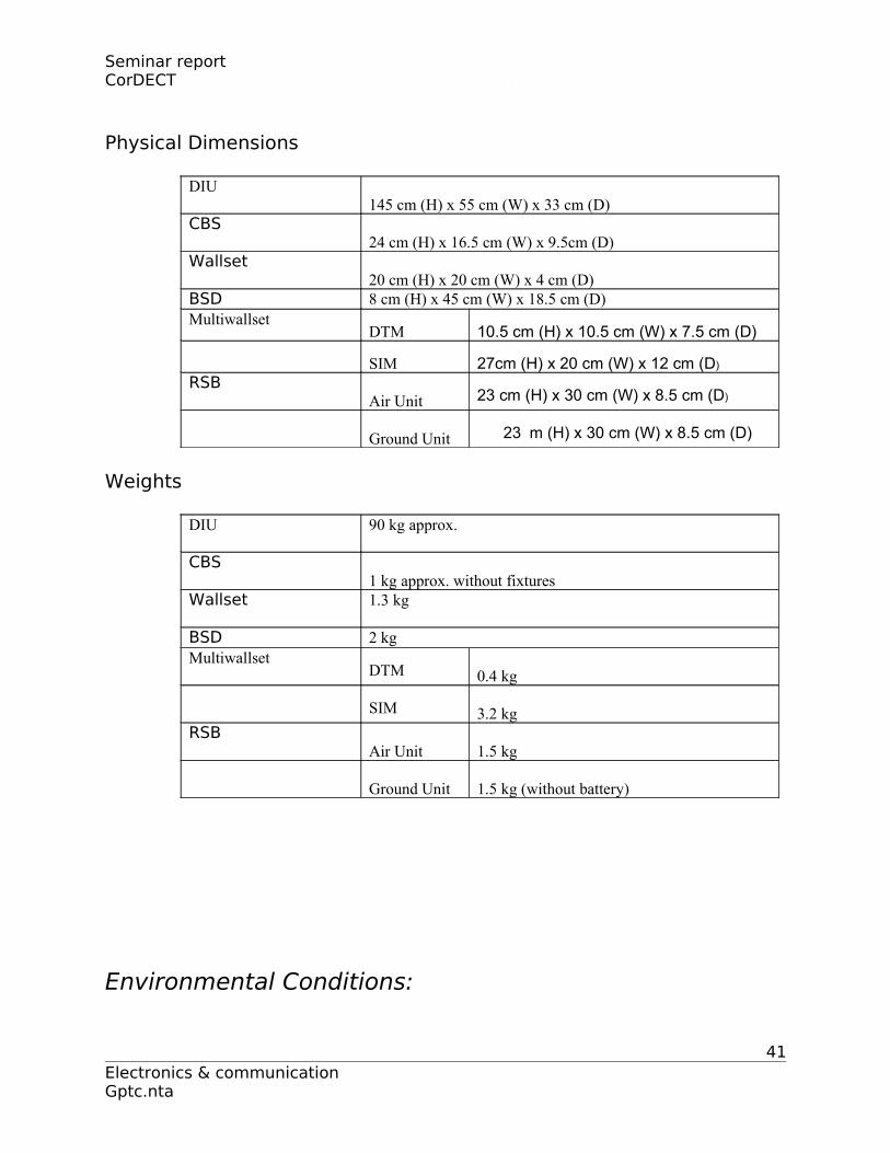
Physical Dimensions
DIU145 cm (H) x 55 cm (W) x 33 cm (D)
CBS24 cm (H) x 16.5 cm (W) x 9.5cm (D)
Wallset20 cm (H) x 20 cm (W) x 4 cm (D)
BSD 8 cm (H) x 45 cm (W) x 18.5 cm (D)Multiwallset
DTM 10.5 cm (H) x 10.5 cm (W) x 7.5 cm (D)
SIM 27cm (H) x 20 cm (W) x 12 cm (D)
RSBAir Unit 23 cm (H) x 30 cm (W) x 8.5 cm (D)
Ground Unit 23 m (H) x 30 cm (W) x 8.5 cm (D)
Weights
DIU 90 kg approx.
CBS1 kg approx. without fixtures
Wallset 1.3 kg
BSD 2 kgMultiwallset
DTM 0.4 kg
SIM 3.2 kgRSB
Air Unit 1.5 kg
Ground Unit 1.5 kg (without battery)
Environmental Conditions:
41Electronics & communication Gptc.nta
Seminar report CorDECT
All the sub-systems meet the Indian Department of Telecommunication’s
environmental specification QM333. They are also compliant to the relevant
ETSI/IEC/CISPR EMI/EMC specifications.
FUTURE ROADMAP
The corDECT system today provides a rich suite of services and features.
These include simultaneous voice and Internet access at 35/70 kbps, a variety of
interfaces to the PSTN including V5.2, segregation of Internet traffic bypassing the
PSTN, several deployment configurations that cater to a range of tele densities
from dense urban to sparse rural, modularity and scalability that make it cost
effective ,and a sophisticated Network Management System. The corDECT
system, however, continues to grow in capabilities. On the anvil are new products
that will keep corDECT ahead of other WLL systems, as the 3G WLL system of
choice for operators worldwide.ETSI has standardized the DECT Packet Radio
Service (DPRS) to enable DECT to meet 3Grequirements for fixed and portable
applications .DPRS leverages the high bit rate of DECT(1.152 Mbps) and its rich
control-plane functionality to provide 3G services. The DECT physical layer has
been upgraded to include the higher bitrates of 2.304 and 3.456 Mbps. The
modulation has also been upgraded in aback ward-compatible fashion so as to
allow improved link budgets. DECT, with its established base and new upgrades, is
thus a front-runner for cost-effective 3G fixed (i.e., WLL) applications .The next
few sections describe briefly the advanced features that corDECT will provide in
the near future.
Towards Always-on Internet Access
42Electronics & communication Gptc.nta
Seminar report CorDECT
Internet access is characterized by bursts of packets with long periods of
inactivity. If the wireless connection is suspended during inactive periods and
resumed quickly when there is a burst of traffic, the available wireless channels
can be used by a much larger number of subscribers. DECT provides for such
suspension and quick resumption of connections, using its powerful control-plane
signaling protocols. Development is in progress to build this new capability into
the corDECT system. When it is available, a very large fraction of the
1000subscribers in each system can be logged onto the Internet simultaneously and
remain logged on for as long as desired.
Packet-Switched High Speed Internet Downloading
It is highly desirable for an user to have the abilityto download from the
Internet at a high peak bitrate, even if the download-channel is sharedby many
users, each accessing it when needed. The bursty nature of Internet access ensures
thata user can get a significant fraction of the peak bitrate whenever he needs
it.The high bitrate of the DECT air interface iseminently suited for providing this
type of service. A major new development of the corDECT systemunderway is a
packet-switched shared downlink Internet channel at 384 kbps. It will be possible
for each sector in a cell to have one such shareddownload channel. A subscriber
terminalaccessing this channel picks off the data meantfor itself. With this service,
a subscriber will beable to download web pages and files at the peak bitrate of 384
kbps. Further, he will be sharingthis fast channel only with the subscribers in the
sector he belongs to.A new subscriber terminal with a high-speed(10BaseT/USB)
data interface port is also underdevelopment to support this service
More Integration for Cost- Effectiveness
43Electronics & communication Gptc.nta
Seminar report CorDECT
A next-generation subscriber terminal is under development which is
more integrated and compact. It will provide several options: one voice line, two
voice lines, or one voice line + one Internet port. A variant of this new product that
has some architectural similarity to the Multiwallset (MWS) is also on the anvil. In
this product, there is an outdoor unit similar to the DTM of MWS. A small indoor
unit connected to it using one copper pair provides the same three options listed
above, while obviating the need for RF cabling.
New Multiwallset Developments
Under development is a MWS that will permit one to serve 8/12/16
subscribers, with blocking whenever four simultaneous calls are in progress. This
will reduce the per-line cost dramatically and enable an operator to serve the
hitherto unviable low-usage subscribers.
Increased Scalability
The corDECT system is unique today in the respect that the cost of the DIU,
representing the up-front investment, is a small fraction of the total cost. This
ensures that the per-line cost is modest even for a 250-line corDECT system. A
new cost-effective, highly integrated mini-DIU will be available soon for a 50-line
system and also for a 150-line system. These versions will also reduce significantly
the physical infrastructure requirements for housing the DIU.
VoIP in corDECT
The corDECT system employ DSP’s extensively. As there is a powerful
DSP in every Wallset, the voice signals can be converted to/from packets at the
Wallset themselves, transmitted on air in packetized form and thence to the
44Electronics & communication Gptc.nta

Seminar report CorDECT
Internet through a gateway at the DIU. Thus, the corDECT system can be made
VoIP compatible in a very efficient and cost-effective manner.
New Air Interface
The new DECT air interface supports a maximum bit rate of 3.456 Mbps
with fall-back options of 2.304 Mbps and 1.152 Mbps. The link budget is also
better due to improved sensitivity. The new air interface enables the use of
sophisticated techniques like sequence estimation and turbo coding to
achieve superior link performance. This new air interface will enable corDECT to
increase traffic capacity and Internet access speed, without increasing the
bandwidth required. It will also give better coverage due to the improved link
budget. This development effort is also underway. When it is available, corDECT
will surpass the performance of all other 3G systems, which will typically support
only 384 kbps Internet access for fixed applications and at most 2 Mbps when one
is sufficiently close to the Base Stations.
Installation Planning
For planning of an access network based oncorDECT and other products, the
TeNeT Group will soon release CygPlan which will be availablefrom Midas
Communication Technologies Ltd. This GIS-based tool runs on MS-Windows and
the plans are stored in a MS-Access database.Given the expected subscriber base,
CygPlancomputes the number of CBS’s, DIU’s and other components required, the
backhaul bandwidthfor voice and IP, the bill of quantities, and costs. CygPlan
ensures that various hardwareconstraints are not violated. If the operator enters the
building heights and other topological detailsof the area, CygPlan will predict the
coverage area of each CBS. The operator can then repositionCBS’s to ensure 100% 45
Electronics & communication Gptc.nta
Seminar report CorDECT
coverage of the service area. The propagation model can alsouse measured signal
levels from a survey, whereavailable.
APPENDIX DIGITAL ENHANCED CORDLESS
TELECOMMUNICATIONS
The DECT standard proposed by the European Telecommunication
Standards Institute (ETSI) is meant for providing wireless access to networks of
various types, from the PSTN to LAN’s. It deals only with the task of defining the
air interface between subscriber terminal and Base Station. The mode of
connecting the DECT-based Wireless Local Loop system to the PSTN and Internet
is left to the service provider.DECT has been specified to make possible low cost
subscriber terminals, high subscriber density with heavy call-traffic levels, wire
line quality voice, modem/fax capability, 32/64 kbps and higher data rate services,
all with a modest spectral allocation of 20 MHz The key technical advances
incorporated in DECT when compared to prior standards that make all this
possible are:
(a). dynamic channel selection,
(b). microcellular Architecture
(c).channels with multiple data rates and
(d).cost-effective modulation/demodulation techniques.
The next two sections focus on some of the key features of the
DECT standard.
DECT: Some Salient Features:
46Electronics & communication Gptc.nta
Seminar report CorDECT
Frequency Band: The RF band originally allotted to DECT is 1880 –
1900 MHz, though the entire 20 MHz need not be employed by each system.
All DECT-based systems including private and public systems operate on the
common band with no requirement for regulation. An extended DECT band
that includes the 1900 – 1935 MHz band is also defined.
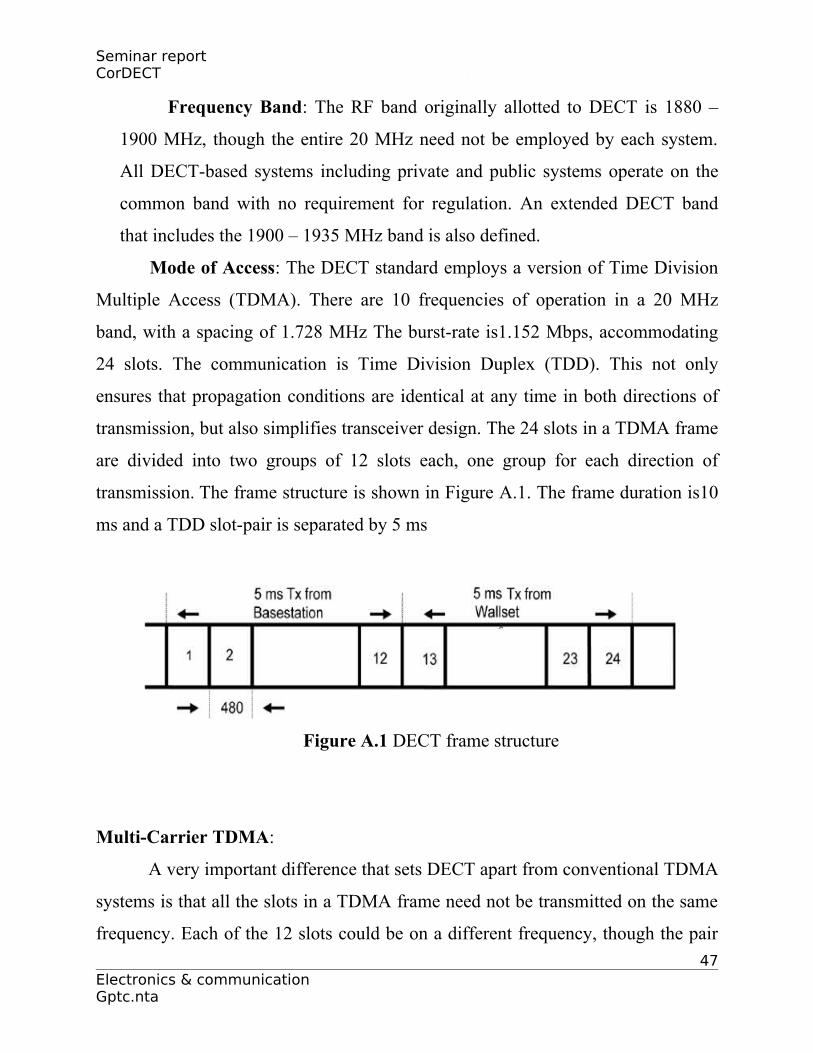
Mode of Access: The DECT standard employs a version of Time Division
Multiple Access (TDMA). There are 10 frequencies of operation in a 20 MHz
band, with a spacing of 1.728 MHz The burst-rate is1.152 Mbps, accommodating
24 slots. The communication is Time Division Duplex (TDD). This not only
ensures that propagation conditions are identical at any time in both directions of
transmission, but also simplifies transceiver design. The 24 slots in a TDMA frame
are divided into two groups of 12 slots each, one group for each direction of
transmission. The frame structure is shown in Figure A.1. The frame duration is10
ms and a TDD slot-pair is separated by 5 ms
Figure A.1 DECT frame structure
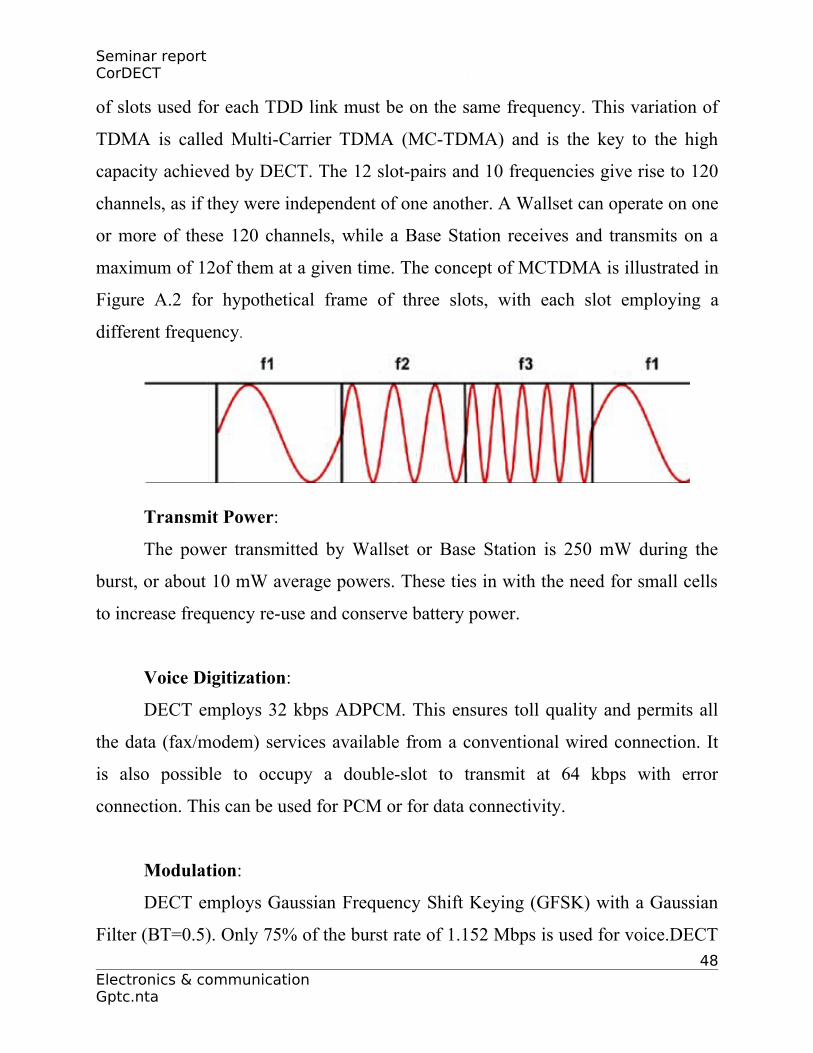
Multi-Carrier TDMA:
A very important difference that sets DECT apart from conventional TDMA
systems is that all the slots in a TDMA frame need not be transmitted on the same
frequency. Each of the 12 slots could be on a different frequency, though the pair
47Electronics & communication Gptc.nta
Seminar report CorDECT
of slots used for each TDD link must be on the same frequency. This variation of
TDMA is called Multi-Carrier TDMA (MC-TDMA) and is the key to the high
capacity achieved by DECT. The 12 slot-pairs and 10 frequencies give rise to 120
channels, as if they were independent of one another. A Wallset can operate on one
or more of these 120 channels, while a Base Station receives and transmits on a
maximum of 12of them at a given time. The concept of MCTDMA is illustrated in
Figure A.2 for hypothetical frame of three slots, with each slot employing a
different frequency.
Transmit Power:
The power transmitted by Wallset or Base Station is 250 mW during the
burst, or about 10 mW average powers. These ties in with the need for small cells
to increase frequency re-use and conserve battery power.
Voice Digitization:
DECT employs 32 kbps ADPCM. This ensures toll quality and permits all
the data (fax/modem) services available from a conventional wired connection. It
is also possible to occupy a double-slot to transmit at 64 kbps with error
connection. This can be used for PCM or for data connectivity.
Modulation:
DECT employs Gaussian Frequency Shift Keying (GFSK) with a Gaussian
Filter (BT=0.5). Only 75% of the burst rate of 1.152 Mbps is used for voice.DECT 48
Electronics & communication Gptc.nta
Seminar report CorDECT
employs ADPCM for its high voice quality and GFSK because transceiver cost is
reduced. By throwing in generous signaling capacity, DECT is able to employ a
very sophisticated channel selection procedure. This is the most important aspect
of DECT which sets it apart from existing cellular systems and is discussed next.
Channel Allocation: Mobile Cellular Systems hitherto employ the so-
called Fixed Channel Allocation (FCA) approach. Here, the available channels are
distributed among neighboring cells in a planned fashion, depending on traffic
needs. Channels are reused at appropriate distances based on the terrain, transmit-
power, antenna height, etc. Channels are allocated from the allotted set to users on
demand by the Base Stations and hand-off is controlled by the network of Base
Stations as the mobile user crosses over into neighboring cells. Systems like GSM
employ Mobile-Assisted Hand-Off (MAHO) but the hand-off is still centrally
controlled. When deciding the re use distance in an FCA-based system, one needs
to make allowance for shadowing (due to obstructions). Re-use is decided based on
worst-case scenarios, assuming the best propagation path for the interference and
worst-case shadowing of the desired signal. The DECT standard employs a
completely decentralized channel allocation procedure called Dynamic Channel
Selection (DCS) or Adaptive Channel Allocation (ACA). In this approach, the
available set of channels is not distributed a priori among the cells. Any Wallset
can set up a call on any of the channels, deciding on the one it will use at a given
time by measuring the signal strength in that channel at its geographical location.
The so-called received signal strength indicator (RSSI) is used for this purpose.
Based on a table of RSSI measurements for all channels, which is continuously
updated, the Wallset selects the strongest Base Station signal received at the given
location at that time to lock onto, and the quietest channel to communicate with the
Base Station. This scheme requires that Base Stations transmit some signal even if
no calls are in progress, i.e., a “beacon”, or dummy bearer in DECT parlance, is a 49
Electronics & communication Gptc.nta

Seminar report CorDECT
must when he Base Station is idle. In the dynamic channel selection section, we
take a closer look at DCS
Encryption and Authentication:
DECT provides encryption of the voice signal or data, to prevent
eavesdropping. Authentication allows one to curb unauthorized use of the Wallset.
Dynamic Channel Selection
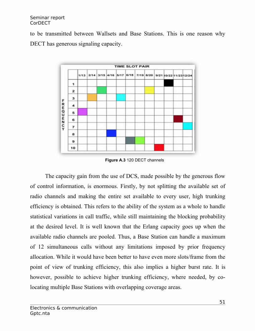
In a MC-TDMA system, a channel is specified by a time-slot/frequency
combination. Thus, each Wallset must make RSSI measurements on each of the 10
frequencies in each time slot. There are thus 120 channels in DECT (for a 20 MHz
band) to choose from. Each channel is specified by a frequency and pair of time-
slots (for TDD communications). Figure A.3 depicts the available choice as a
matrix. The shaded boxes indicate channels that may be in use at a given time and
place. The time slots are synchronized to the frame of the Base Station the Wallset
is currently locked to, or to a local frame clock if the Wallset is not locked to any
Base Station yet. In a TDMA system, the transceiver is idle when not receiving or
transmitting a burst. So, RSSI measurements can be performed in all other slots on
all frequencies. With DCS, hand-over may become necessary even if the Wallset
under consideration does not move, because of the autonomous decisions taken by
other Wallsets. In DECT, the switch-over to another channel is made as soon as a
better channel is found by RSSI measurements, without waiting for the current
channel to deteriorate. The call is then simultaneously transmitted on both channels
(which is easily accomplished in a TDMA system by transmitting in two slots) and
a seamless switch-over is accomplished. In order to facilitate this type of self-
organizing, Wallset-arbitrated hand-over, a fair amount of control information has
50Electronics & communication Gptc.nta
Seminar report CorDECT
to be transmitted between Wallsets and Base Stations. This is one reason why
DECT has generous signaling capacity.
Figure A.3 120 DECT channels
The capacity gain from the use of DCS, made possible by the generous flow
of control information, is enormous. Firstly, by not splitting the available set of
radio channels and making the entire set available to every user, high trunking
efficiency is obtained. This refers to the ability of the system as a whole to handle
statistical variations in call traffic, while still maintaining the blocking probability
at the desired level. It is well known that the Erlang capacity goes up when the
available radio channels are pooled. Thus, a Base Station can handle a maximum
of 12 simultaneous calls without any limitations imposed by prior frequency
allocation. While it would have been better to have even more slots/frame from the
point of view of trunking efficiency, this also implies a higher burst rate. It is
however, possible to achieve higher trunking efficiency, where needed, by co-
locating multiple Base Stations with overlapping coverage areas.
51Electronics & communication Gptc.nta
Seminar report CorDECT
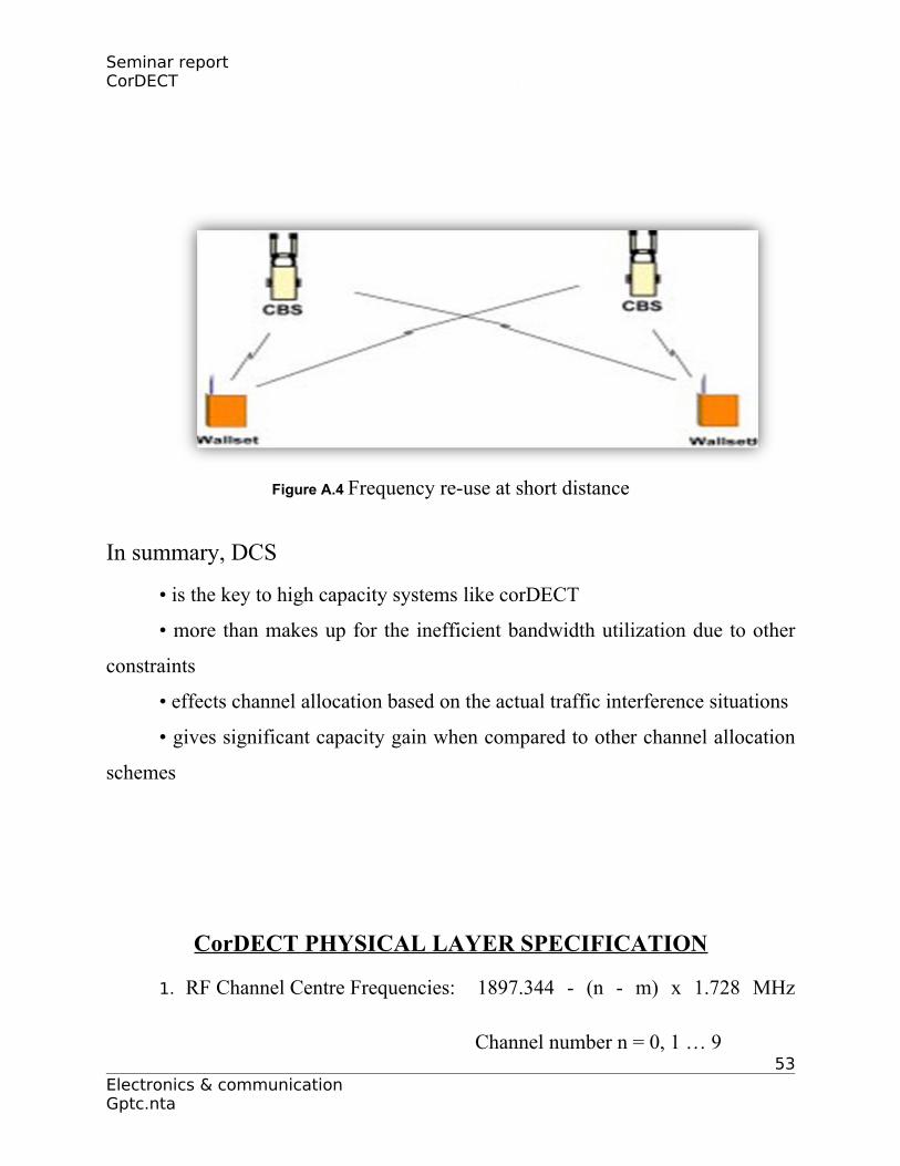
A second gain from the use of DCS is that channels are re-used based on the
instant situation and re-use distance can sometimes be very small. Consider the
example shown in Figure A.4. The Wallsets and Base Stations are so located that
either Wallset, when operating alone, could communicate with either Base Station.
However, even in the situation when both are simultaneously active, it is possible
for each Wallset to communicate to the Base Station nearer to it on the same
channel. This is because it is the carrier signal-to-interference (C/I) ratio that
determines whether the channel is good enough. Even though the signal from the
farther Wallset is good enough for communication in the absence of any other
transmission on the channel, the interference that this causes to the signal from the
nearer Wallset is too small to matter. Thus, a channel can be re-used even at short
distances depending on the interference profile as seen by each Wallset.
Finally, Base Stations may be added to the system as and when needed to
cater to increased traffic and no co-ordination or planning is needed. Indeed,
multiple Base Stations can even be colocated. More than one Base Station can be
reached from any location and the trunking efficiency goes up. Incidentally, DECT
systems belonging to different operators, public or private, can co-exist and operate
over a common frequency resource without co-ordination.
While DCS is the key to high capacity with small cells, the use of DECT in
large cells with low subscriber density is not precluded. The improved sensitivity,
compact antennas, and timing adjustment scheme implemented in corDECT
permit coverage up to 10 km under line-of-sight conditions. Also, the range can be
extended to as much as 25 km in the case of the RBS employing high gain
antennas that increase the link budget.52
Electronics & communication Gptc.nta
Seminar report CorDECT
Figure A.4 Frequency re-use at short distance
In summary, DCS
• is the key to high capacity systems like corDECT
• more than makes up for the inefficient bandwidth utilization due to other
constraints
• effects channel allocation based on the actual traffic interference situations
• gives significant capacity gain when compared to other channel allocation
schemes
CorDECT PHYSICAL LAYER SPECIFICATION
1. RF Channel Centre Frequencies: 1897.344 - (n - m) x 1.728 MHz
Channel number n = 0, 1 … 953
Electronics & communication Gptc.nta

Seminar report CorDECT
Channel offset m = 0 – 21
e.g.,
m = 0 for 1880 – 1900 MHz
m = 12 for 1900 – 1920 MHz
m = 17 for 1910 – 1930 MHz
2. TDMA Frame Duration: 10 ms
3. Transmission Bit rate : 1.152 Mbps
4. TDMA Slot Length : 480 bits, with 32 bits for synchronization,
64 bits for signaling and 324 bits for voice
and CRC.A double slot of 960 bits is also
defined.
5. Modulation : Gaussian Frequency Shift Keying
6. Frequency Deviation : +288 kHz (nominal) for all-ONE bit pattern and
-288 kHz (nominal) for all-ZERO bit pattern
7. Transmit Power : +24 dBm nominal
8. Spurious Emission : < -8 dBm in adjacent channels
< -30 dBm, 2 channels away on either side
< -44 dBm, 3 channels away on either side
< -47 dBm in all other channels except for one
instance of -33 dBm.
9. Sensitivity : at -85 dBm (typical), BER better than 10-5
at -90 dBm (typical), BER better than 10-3
54Electronics & communication Gptc.nta
Related Documents