1 1. Introduction to IN 1.1 Introduction The purpose of this module is to provide the student with an introduction to the basic concepts behind Intelligent Networks. All the areas covered in this module are covered at an overview level. More detail is provided in the later modules. Figure 1.1 Module Objectives. 1.2 What is IN? The term “Intelligent Network” means a network capable of meeting mar- ket demands for new services in a flexible and cost effective way. Erics- son’s products for advanced IN enable service providers to structure and program a wide range of advanced network services. The products, based on the AXE system and upon general-purpose computers, are capable of meeting the requirements for service availability to all subscribers in the network. 1.3 Driving Forces for IN There are many different driving forces for IN today. The telecom market has changed for the operators due to the deregulation. The monopolies of the old telecom administrators have ended and they now have to compete with other operators on the same market. That implies new demands to the operators to find ways to attract the customers. The IN concept makes it possible to meet the increasing market demands for more advanced services, in a faster, more flexible and thus more cost- effective way. The introduction of IN services in the network contributes to higher reve- nues for an operator. Due to the availability of a wide range of new attrac- Module Objectives After completing this module the participant will be able to: • Describe the purpose of the IN concept • Identify the different IN nodes • Describe the standardisation of IN and Ericsson’s IN release

Welcome message from author
This document is posted to help you gain knowledge. Please leave a comment to let me know what you think about it! Share it to your friends and learn new things together.
Transcript

1
1. Introduction to IN
1.1 IntroductionThe purpose of this module is to provide the student with an introduction to the basic concepts behind Intelligent Networks. All the areas covered in this module are covered at an overview level. More detail is provided in the later modules.
Figure 1.1Module Objectives.
1.2 What is IN?The term “Intelligent Network” means a network capable of meeting mar-ket demands for new services in a flexible and cost effective way. Erics-son’s products for advanced IN enable service providers to structure and program a wide range of advanced network services. The products, based on the AXE system and upon general-purpose computers, are capable of meeting the requirements for service availability to all subscribers in the network.
1.3 Driving Forces for INThere are many different driving forces for IN today. The telecom market has changed for the operators due to the deregulation. The monopolies of the old telecom administrators have ended and they now have to compete with other operators on the same market. That implies new demands to the operators to find ways to attract the customers.
The IN concept makes it possible to meet the increasing market demands for more advanced services, in a faster, more flexible and thus more cost-effective way.
The introduction of IN services in the network contributes to higher reve-nues for an operator. Due to the availability of a wide range of new attrac-
Module Objectives
After completing this module the participant will be able to:
• Describe the purpose of the IN concept
• Identify the different IN nodes
• Describe the standardisation of IN and Ericsson’s IN release

IN 2.3 Service Testing Course
2
tive IN services the traffic as well as the number of successful calls will increase.
The great advantage of IN, which has also been one of the driving forces behind its introduction, is that it drastically has reduced the time of intro-ducing a new service in the network, from 2-4 years down to six month and even less.
Other advantages are that a certain service in the network is controlled from one or a few central points (SCPs) instead of a great number of dis-tributed points which is the case for conventional supplementary services. This greatly facilitates all administrative procedures like introduction, change or withdrawal of a service. Centralised control and administration also gives a better overview to the operator of the services in the network.
1.4 Background to INThe term "Intelligent Network" was phrased within BELLCORE in 1984. It started as a concept to help the newly born Regional Bell Operating Companies (RBOC) in the United States to become more competitive in the new deregulated environment.
IN was, and still is, inspired by the advances in modern operation system and data base technologies. One of the scopes has been to bring computer vendors and products into the telecommunications market.
In international standardisation the task is gradually being reached in defining IN as:
"A telecommunications network with service independent capabilities that allows the network service providers or operating companies to independ-ently define and competitively provide new network services".
1.5 Introduction to the IN ConceptIN services are stored centralised in the network in an SCP (Service Con-trol Point). The SCP acts as a data base where the IN services are stored and executed.
The IN services are normally created with the help of SMAS which is a user friendly tool for creation and handling of IN services. The Ericsson way of creating IN services is called "The Service Script Concept". When a service has been created in SMAS it is installed in the SCP where it is executed. SMAS is an application within TMOS which is Ericsson’s con-cept for centralised operation and maintenance.
No calls (speech circuits) are switched in the SCP. Switching of IN calls are done in the SSP (Service Switching Point). The SSPs are usually tran-sit exchanges with some additional software. The SSP and the SCP are the two most important nodes in an IN network.
When an IN call is received by an SSP, the SSP needs to send a request to an SCP and ask how the IN call shall be switched. This type of information exchange between the SSP and the SCP is carried out with the help of IN

Introduction to IN
3
signalling (i.e. the INAP protocol). INAP is part of the signalling system #7 and lies on top of the protocols: TCAP, SCCP and MTP.
Figure 1.2Components of the IN Network
It is important to distinguish between the IN functions and the IN nodes. In Figure 1.2 we have the following:
SSF - Service Switching Function in a Service Switching Point (SSP)
SCF - Service Control Function in a Service Control Point (SCP)
SRF - Specialised Resource Function in a Intelligent Peripheral (IP)
SDF - Service Data Function in a Service Data Point (SDP)
CCF - Call Control Function (TCS in AXE) in a SSP
INAP - Intelligent Network Application Part, the IN protocol
SCE - Service Creation Environment in the Service Management Applica-tion System (SMAS)
SMS - Service Management System (in SMAS)
The SCF has the service control for an IN service while the SSF has the call control (on behalf of the SCF) for the IN calls.
SDF
SCF
SCP
SDP
SCE
SMS
SMAS
IN Service Control
INAP
SSF
CCF
SSP
SRF
IP
IP
SignallingSpeech, data
IN Call Control
IN Service Management
IN 2.3 Service Testing Course
4
1.6 Differences between IN 2.1 & CS1The functions of IN 2.1 and CS1 are not the same. CS1 has operations for Networked IPs which is not a part of IN 2.1, while IN 2.1 has more capa-bilities to use announcements during the call phase and to different call parties.
IN 2.1 contains the SDF interface. This is kept in the CS1 environment, but with new SIBs. This interface is still an Ericsson proprietary interface, and in the IN 2.2 release it will therefore be denoted as CS1(+).

Introduction to IN
5
1.7 IN Network Nodes
1.7.1 SSP - Service Switching PointThe SSP is responsible for all functions concerning switching of IN serv-ices. The switching is carried out as a result of service execution in the SCP. There is a continuous flow of information between the SSP and the SCP. The SCP decides about the switching and gives order to the SSP. The SSP informs the SCP about the subscriber activity and the call status in the switch.
There are a number of important areas handled by the SSP. All these areas are described in the coming modules. SSF is divided into five subfunctions in IN 2.1:
1. General
2. Triggering and Invocation
3. Congestion Control
4. Special Resources
5. Charging
A new CS1 SSF has been developed and added in IN 2.2. The subfunc-tions are now called:
1. Triggering (changed from IN 2.1)
2. IN Call Control (new)
3. Dialogue Control (new)
4. Mass Call Service (new)
5. Special Resources
6. Charging.
Triggering occurs when a Trigger Detection Point (TDP) is armed and the criteria for this Detection Point (DP) is met during the call process. In the SSP a new parameter called In Service Triggering (IST) is introduced.
IN Call Control is the interface in SSF towards the Call Control Function (TCS) in order to allow SCF to control the call processing and the connec-tivity of the call.
Dialogue Control makes all established dialogues behave according to determined rules. These rules are supervised by so called Finite State Machines (FSMs) in the SSF. These FSMs reflects the state of the dia-logues and controls the reception and sending of operations between the SSF and the SCF.
Mass Call Services contains two functions (Call Gap and Service Filter-ing) for protecting the SCF against overload as well as filtering of calls for televoting.

IN 2.3 Service Testing Course
6
1.7.2 SCP- Service Control PointThe purpose of the Service Control Function (SCF) is to process the logic and data which makes a service and to interact with the SSF when appro-priate in order to perform the service in the network. The SCF can be implemented in two ways:
1. As a stand-alone node in the network called the Service Control Point (SCP)
2. As part of a node which has both SSF and SCF functions, called the Service Switching and Control Point (SSCP)
3. The SCF can exist on two platforms:
4. As a software-only application on a telecommunications platform such as AXE. In this case the SCP is referred to as an SCP-T.
5. As a set of software programs on a general purpose computer such as UNIX. In this case the SCP is referred to as an SCP-G (General purpose computer).
1.7.3 SSCP - Service Switching Control PointSo far we have mentioned two different types of IN nodes, the SSP (Serv-ice Switching Point) and the SCP (Service Control Point). The software functions required to realise these IN nodes are mainly found in the AXE subsystem SES (Service provisioning subsystem). SES is divided into two functions, the SSF (Service Switching Function) to realise the SSP and the SCF (Service Control Function) to realise the SCP.
Both the SCP and the SSP are today AXE nodes. The reason for the SSP to be an AXE node is easy to understand as the SSP is always a telephony exchange. The SCP, being a data base, is today built on the TPC (Telecom Purpose Computer), i.e. the AXE platform using the APZ processor. In IN phase 2.2 an SCP built on a GPC (General Purpose Computer), i.e. a UNIX platform will also be available.
The SSF is usually implemented in a transit exchange but it can also be implemented in a local exchange. One type of services requiring imple-mentation in a local exchange are services that can be subscribed on (e.g. Call forwarding). When a subscriber is subscribing on "Call forwarding" and it is activated, all calls to his phone are forwarded to a pre-pro-grammed phone number. It is only the local exchange that can be informed about how a specific subscribers phone is programmed. These services are today mainly implemented as supplementary services.
Mass call services, e.g. Televoting, can be another reason for having the SSF in the local exchange. During mass calling the transit exchanges will many times get to congested to be able to handle all calls. In these cases the calls can be better taken care of by the SSF in the local exchange.
The SSP and the SCP distributes the IN functionality in the network. Except this distributed way there is also the possibility of implementing all functionality in one node, the SSCP (Service Switching Control Point). This is a combined node including both the SSF and the SCF. The SSCP

Introduction to IN
7
has its main advantages if there is mainly analogue transmission and no #7 signalling available in the network. The SSCP was the first IN node devel-oped, that was in IN phase 1.
There exist also another IN node, the SDP (Service Data Point) which among other tasks can be used to store customer data. An IP (Intelligent Peripheral) can also be an IN node. An IP handles equipment for announcements and reception of digits from the subscribers.
Figure 1.3IN Nodes
1.7.4 SCP-G - Service Control Point-General Purpose ComputerThe SCP-G provides Service Control Point functionality on a General Pur-pose Computer platform.
Since it is built on a general purpose computer platform, the SCP-G has advantages like scalable configurations from low-end to high-end systems and openness in terms of adding third party products. It is compliant with the ITU-T Capability Set 1 (CS1) protocol, plus a subset of the Ericsson INAP protocol (EINAP).
The SCP-G has built-in high availability that allows it to continue opera-tion after the failure of any single component.
The SCP-G is managed by Ericsson’s Service Management Application System (SMAS), which offers service creation, provisioning, and network management capabilities. SMAS can also be used to manage and provision Ericsson’s AXE SCP (SCP-T).
SCF
SSF
SSP
SCP
LESSF+SCF
SSCP
LE
IN 2.3 Service Testing Course
8
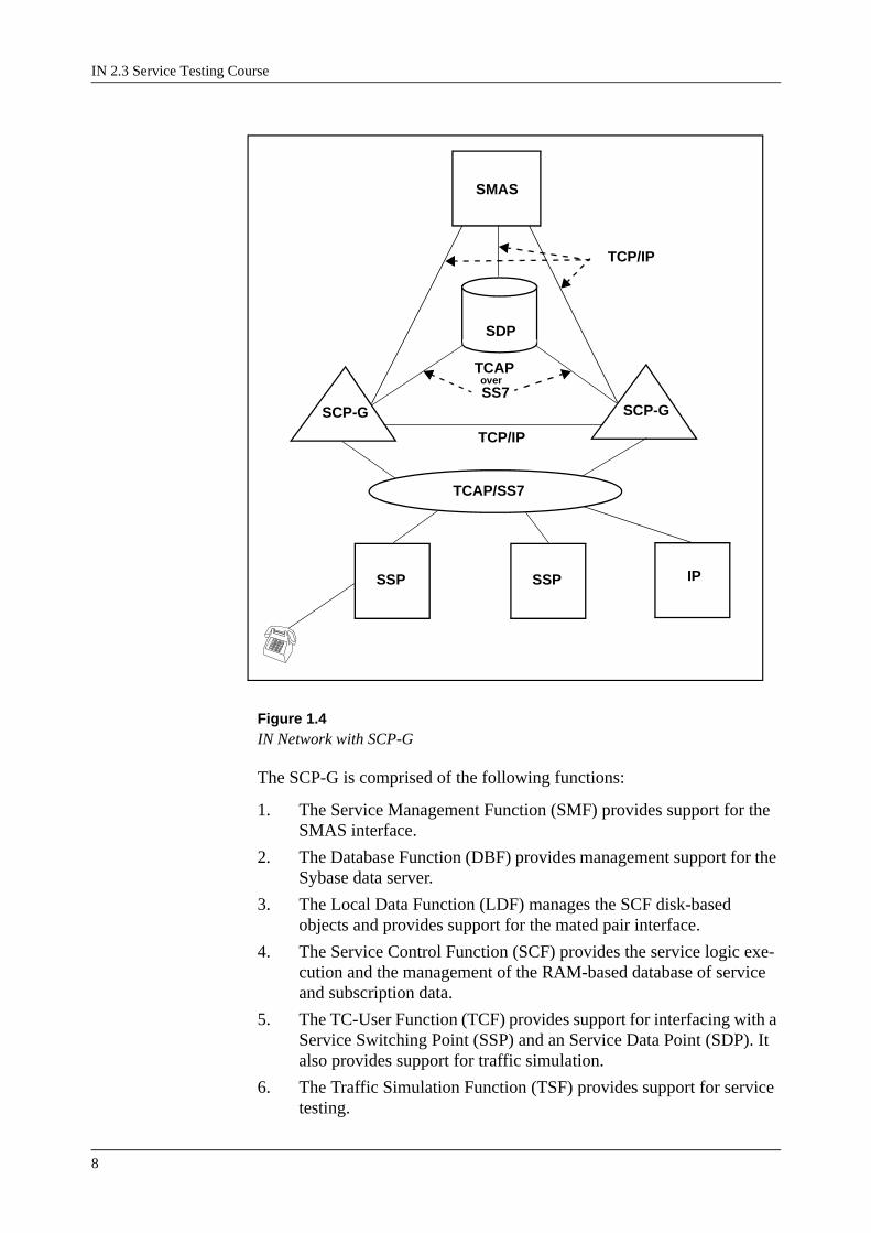
Figure 1.4IN Network with SCP-G
The SCP-G is comprised of the following functions:
1. The Service Management Function (SMF) provides support for the SMAS interface.
2. The Database Function (DBF) provides management support for the Sybase data server.
3. The Local Data Function (LDF) manages the SCF disk-based objects and provides support for the mated pair interface.
4. The Service Control Function (SCF) provides the service logic exe-cution and the management of the RAM-based database of service and subscription data.
5. The TC-User Function (TCF) provides support for interfacing with a Service Switching Point (SSP) and an Service Data Point (SDP). It also provides support for traffic simulation.
6. The Traffic Simulation Function (TSF) provides support for service testing.
SMAS
SSP IP
SS7
TCAP/SS7
TCAP
SDP
SSP
SCP-GSCP-G
over
TCP/IP
TCP/IP

Introduction to IN
9
7. The Service Node Application Platform (SNAP) provides the proc-ess management, configuration management, alarm handling, data logging and OA&M functions.
8. The SS7 stack has responsibility for handling the SS7 protocol stack and for supporting traffic related statistics.
The SCP-G is designed to be a highly available system. It consists of one or more Functional Processors (FPs). An FP represents a single UNIX server in the SCP-G and may have multiple Central Processing Units (CPUs).
In most cases, the above functions can be distributed across multiple FPs or can reside on the same FP. The exceptions being SCF and TCF, which must reside on the same FP. There are generally two instances for each type of function, one in a primary mode and one in a stand-by mode. When an FP fails that contains a primary function the corresponding stand-by function becomes primary. Until the failed FP is returned to a normal state, no stand-by function is available.
It is also possible that for a given function there is no active stand-by func-tion. Although there is no active stand-by function, there is a designated FP on which the function assumes primary responsibilities if the FP that is currently running as the primary function fails.
Network transactions (i.e., traffic) involve the primary SS7 Stack, the pri-mary TCF and the primary SCF. The stand-by SS7 Stack, DBF and SCF do not participate in the handling of network transactions, but are active in a “warm stand-by” mode. The stand-by functions will become primary and take over traffic handling in case of a failure of a primary function.
Updates from SMAS are handled by the primary SMF then propagated to the primary and stand-by DBF. After successful completion by the DBF, the update is relayed to the primary and stand-by SCF. In this way both disk databases, and both RAM databases stay synchronized.
1.7.5 SDP - Service Data PointThe Ericsson Service Data Point (SDP) is a database storage and retrieval system that has been developed as an integral part of the Intelligent Net-work (IN) product offerings from Ericsson. The SDP is used to store and handle large quantities of subscriber data, which can significantly increase the number of subscribers supported by the Service Control Point (SCP).
The SDP consists of the following:

IN 2.3 Service Testing Course
10
• Service Data Point (SDP) application software
• Service Node Application Platform (SNAP) software
• EINAP TC-User network communication from the UTS subsystem
• SYBASE® database management system
• Hewlett-Packard™ (HP) 9000 series hardware
• Hewlett Packard™ - UNIX (HP-UX) operating system environment
• HP Signalling System No. 7 (SS7) hardware and software
This HP equipment is a highly available system, it is not fault tolerant.
The customer data held by the SDP can be managed by a Service Manage-ment System (SMS).
When SDPs are configured as mated pairs there is a problem with cus-tomer data as it is often changed, e.g. the PIN code in the UPT service. If data is changed in one SCP the other SCP in the pair needs to be updated. The updating procedure between SCPs is quite time consuming as it has to be carried out via SMAS.
Many of the problems with customer data can be solved with an SDP (Service Data Point), introduced in IN phase 2.1. One purpose of the SDP is to store subscriptions, i.e. customer data (CDMs), centralized in the net-work. Large volumes of data can be stored and no update between SCPs will any longer be needed. The SCPs will still store the service logic as well as local- and global data. During service execution the SCP will retrieve the customer data from the SDP.
The installation of a subscription from SMAS to the SCP takes much longer time than the same procedure from SMAS to the SDP. That is due to (among other things) the simplified database structure of the SDP.
Figure 1.5SDP - Service Data Point
HD
PrimaryServer
SecondaryServer
HD HD HD
Ethernet
#7-link #7-link
SDPSDP - Service Data PointHD - Hard Disk
#7 = Signalling System #7

Introduction to IN
11
The SDP can be configured in different ways, one configuration is shown in Figure 2.2. In this case the SDP consists of two separate servers each of them connected to a hard disk pair. In this SDP the same customer data is stored on four different hard disks. Each of the servers have a separate #7 signalling connection and they are interconnected over Ethernet.
1.7.6 IP - Intelligent PeripheralWhen a service involves interaction with a user, IN will use an Intelligent Peripheral (IP). An Intelligent Peripheral can be defined as a physical entity that implements the IN Special Resource Function. The functions of this special resource can include one or more of the following:
• to make an announcement to a connected leg of a IN call (an announce-ment machine)
• to record a message which a service user wants to leave (a listening machine)
• to receive digits from a Dual Tone Multi-Frequency (DTMF) phone (a digit reception device)
• to perform speech recognition
• to provide voice and fax mail facilities
At present, the most common Intelligent Peripherals are those which per-form the first three of the above functions.
There are four types of Intelligent Peripheral:
1. Integrated IP: this is located within an MSC/SSP node. All commu-nication with the IP takes place through the use of internal protocols. It can make announcements and monitor for digits and is under the control of the SCF.
2. Networked IP: this is connected to both an SSF and an SCF directly. Communication with the IP takes place using a standard-ised signalling protocol for IN equipment. It can make announce-ments and monitor for digits and is under the control of the SCF.
3. Stand-Alone IP: this is external to an MSC/SSP node and is not connected directly to the SCF. Communication with the IP takes place using ordinary telephony network signalling protocols. The stand-alone IP can make announcements and monitor for digits. However, results (such as digits) cannot be returned to the SSF and can only be used within the IP itself. Stand-alone IPs are not under the control of the SCF.
4. Advanced IP: this is external to an MSC/SSP node but is associated with an MSC/SSP. It exists on TCP/IP connected workstations and is connected to the MSC/SSP. Thus, the advanced IP enables the connection of multi-vendor audio and information systems to the network for the purpose of user interaction. This provides robustness and scalability in the network, because the SSF distributes all processing of user interaction features to the advanced IP.

IN 2.3 Service Testing Course
12
Figure 1.6All types of IP.
SCPSSCPIP
IP IP IP
IP
CCF SSF
IP
Network IP
Advanced IP
Stand Alone IPIntegrated IP

Introduction to IN
13
1.8 IN StandardsEricsson has undertaken pioneering work in IN and has worked at a more advanced stage than the international standards. Accordingly, Ericsson developed a proprietary specification called Ericsson INAP. Subsequently, INAP standards have been promoted with the ITU-T CS-1 specification and the ETSI Core INAP specification. Although Ericsson INAP and the ITU-T CS-1 specification are very similar in functional terms, the models and operations are different.
Ericsson is actively engaged in developing and promoting international standards for IN. The twin pressures of a significant existing customer base using Ericsson INAP and market demands for CS-1 INAP has neces-sitated the development of Ericsson INAP CS-1+. CS-1+ provides back-ward compatibility for Ericsson INAP and also full compatibility withCS-1.
Ericsson INAP CS-1+ extends INAP CS-1 with additional operations and parameters. The function specifies the INAP operations, parameter descriptions and detailed operational procedures. The operational proce-dures specify the expected behaviour of the functional entities for each operation.
1.8.1 ITU-T Capability SetsThe International Telecommunication Union (ITU) is working to harmo-nise the IN standards worldwide. The ITU-T have defined a set of capabil-ities for the Intelligent Network. The list defines the functionality against which IN vendor equipment is assessed rather than services that are intended to be launched to customers.
The list of recommendations below define the ITU-T Capability Sets:
Q.120 General Series IN Recommendations Structure
Q.1201/1.312 Principles of IN Architecture
Q.1202/1.328 IN Service Plane Architecture
Q.120/1.329 IN Global Functional Plane Architecture
Q.1204 IN Distributed Functional Plane Architecture
Q.1205 IN Physical Plane Architecture
Q.1208 General Aspects of the IN Application Protocol
Q.1290 Glossary of Terms used in the Definition of IN
The goal of the ITU-T is to harmonise IN standards worldwide.
The Q.121x series of recommendations is referred to as the international IN Capability Set (CS-1). CS-1 defines the overall architecture and vocab-ulary. The 14 recommendations contained within CS-1 were ratified in March 1993 and were printed in December of that year.
Q.1211 Introduction to IN CS-1
IN 2.3 Service Testing Course
14
Q.1213 Global Functional Plane for IN CS-1
Q.121 Distributed Functional Plane for IN CS-1
Q.1215 Physical Plane for IN CS-1
Q.1218 IN Interface Recommendations for CS-1.
CS-2 is currently being developed. There are new specifications for per-sonal mobility and international services being added in this standards ver-sion. CS-2 is due to be published in 1997.
1.8.2 ETSI ‘core’ standardsIn 1994, the European Telecommunications Standards Institute (ETSI) defined a ‘core version’ of the ITU-T recommendation that focuses on basic issues. The purpose of the ‘core standard’ is to provide a basic subset that should be implemented. ETSI ‘core’ INAP handles the inter-working functionality required by the CS-1 specification. It is used for inter-work-ing between nodes in a multi-vendor environment. in the future, ETSI will contribute to the development of the ITU-T recommendations.
The ETSI standards map closely against the ITU standards.
Q.1211 Guidelines for CS-1 Standards?
Q.1213 Global Functional Plane for IN CS-1
Q.1214 Distributed Functional Plane for IN CS-1
Q.1215 IN CS-1 Physical Plane
Q.1218 Core INAP.
1.8.3 Bellcore standardsThe term Intelligent Networks was first coined in the mid 1980s (1984) within Bellcore, a research facility of the regional telephone companies in the US. In 1984, the Regional Bell Operating Companies (RBOCs) choose to implement the Freephone 800 service using a central database to handle queries on how to handle the call, modelled on the AT&T system.
In the early 1980’s, Bellcore started work on developing AIN standards in the United States. This work coincided with the telecom deregulation in the US. The first set of specifications, IN/1, were published in 1986. These specifications were used to implement early versions of the Freephone service.
There have been several revisions since and the current set of recommen-dations is AIN 0.1 (following AIN 0.0). The development of AIN 0.2 and AIN 1.0 is ongoing. In time, it is likely that the ITU-T recommendations will incorporate the Bellcore specifications.

Introduction to IN
15
1.8.4 Ericsson standardsIN development work in the Netherlands in 1988 (Phase 1- within the AXE 10 APT 210 08 R4 source system project) resulted in the Ericsson Service Script Interpreter (SSI) concept and a new application for the IN service creation and management called SMAS.
Phase 1.0 introduced the first release of SSI (SSI/1) for the Ericsson SSCP. SSI/1 is contained in the AXE 10 TCS (Traffic Control Subsystem) and contains 34 SIBS called Control Types (CTs). An Ericsson proprietary protocol is used for communication between the SSF and SCF.
In the US (1991), the Ericsson SSI/1 product was used to provide SCF functionality in trials of IN according to United States Bellcore AIN 0.0 standard. This necessitated the development of a non-proprietary SSF-SCF communication protocol according to RBOC Ameritech specifications which were based on the ANSI TCAP standard.
The evolution of SSI/1 began in 1991. It resulted in a functionally richer SSI called SSI/2. IN 2.0 is a platform for local and international transit nodes, based on the AXE 10 APT 210 08 R5
IN 2.0 introduced the following additions into the Ericsson IN portfolio:
• The encapsulation of SSF and SCF software into a dedicated AXE 10 subsystem called the Service Provision Subsystem (SES)
• Stand alone SSP and SCP available through the development of support for communication between standalone SSF and SCF over SS7 TCAP protocol (ITU-T Blue Book version).
• An increase to 79 in the pool of supplied SIBs in the SCF to permit new validation services, as well as the SSI/1 translations services.
• The introduction of a new IN product called Service Data Point (SDP) and support for the Intelligent Peripheral (IP) function through the Eric-sson AST-DR.
• A General Service Adapter (GSA) tool on top of the SMAS/TMOS application for service management and creation
In the US (1992), the Ericsson product SSI/2 was used in trials based on the AIN 0.1 standard from Bellcore. The Bellcore AIN 0.1 standard approximately corresponded to the European standard Capability Set No. 1 (CS 1).
IN 2.1 which was release in 1994, provided the capabilities to create IN services for PSTN and ISDN subscribers.
The IN2.1 SCP is based on the Ericsson Source Systems APT 210 11/3 and APT 210-12/3. Together these support basic telephony (POTS), SS7 signalling Transfer Points (STPs) and ISDN in addition to IN applications at local and transit level in the network.
IN 2.1 introduced the following additions into the Ericsson IN portfolio:
• New services for both end users and operators
• Support for basic ISDN and Signalling Transfer Point STP (SS7) for IN

IN 2.3 Service Testing Course
16
functionality
• Support for connection and inter working with Siemens and Alcatel SSPs through the addition of a product called the Inter Working Unit to the SCP
• SSF- SCF communication using SS7 INAP protocol and the handling of the transport of INAP protocol messages in the form of TCAP mes-sages over SS7.

Introduction to IN
17
1.9 Module Summary• IN is a way of implementing services in the network. These services are
called IN services.
• The node for storing IN services is called the SCP and the node for switching IN calls is called the SSP. These nodes can as well be com-bined into an SSCP.
• IN 2.1 has a different SSF Call Model than the CS1 based SSF
• "Special Resources" includes equipment for sending of announcements to the subscriber and receiving of digits from the subscriber. This type of equipment is implemented as IPs.
• The SDP is a UNIX based node for massive data storage. It has a sim-plified data base structure which speeds up the handling of the data.
• IN (Intelligent Network) started as a concept within BELLCORE in the US in 1984 to help them to become more competitive. This is still the main driving force.

IN 2.3 Service Testing Course
18

SMAS, Red Line Trace
19
2. SMAS, Red Line Trace
2.1 IntroductionThe purpose of this module is to provide the student with an overview of SMAS with an focus on the Audit function and to familiarise the student with the user interface of Red Line Trace, and its functionality with regards to function testing and verification.
Figure 2.1Module Objectives.
2.2 SMAS OverviewEricsson’s products for Intelligent Networks (IN) allow network service providers to structure and program a wide range of advanced network services. The products can supply services to all subscribers in the telecom network. It is the Service Script Interpreter (SSI) in the AXE 10 or SCP-G (SCP-General purpose computer) system that gives these opportunities.
One of Ericsson’s products for IN is SMAS. SMAS provides a user-friendly interface based on graphic presentations, thereby offering a serv-ice provider a way to quickly introduce new, competitive services that meet any customer’s needs.
2.3 What is a “Service”?The modern use of a telephone network implies much more than simply connecting two telephones. In a world where personal and professional relations are increasingly dependent on maintaining communication over considerable distances, it becomes more and more important to have a well-functioning and effective telephone network. The use of telephone services expands the application range of telephone traffic. It becomes
Module Objectives
After completing this module the participant will be able to:
• Explain the main purpose of SMAS
• Understand the functions of SMAS
• Perform an Audit of a service.
• Explain the main purpose of Red Line Trace
• Understand the function of the RLT menu options
• Perform Red Line Tracing of a service.

IN 2.3 Service Testing Course
20
easier to get in touch with people, leave messages, use the phone for mar-keting purposes, and so on.
A few examples will give an idea of the possibilities provided by tele-phone services.
One very useful telephone service is the personal number. Every sub-scriber is given a personal number at which he or she can be reached regardless of his or her whereabouts. The subscriber can specify different numbers where the he/she could be reached. The subscriber can call a cen-tral number and update this information at any time. When the personal number is dialled, the network will attempt to reach the user at each number in turn until all possible values have been tried or until the phone is actually answered. This service also includes the possibility of calling from any telephone and charging the call to the personal number.
Universal number is another service. Imagine that a company, for instance a travel agency, wishes to be reached from a universal number. Depending on the caller’s geographical location, day of the week and time of day, the caller can be connected with different numbers, so that an office which is open is always reached. This is now possible, thanks to advanced service facilities.
Other examples of services are freephone, pre-paid calls, credit-card call-ing, hot line, queuing, tele-voting, information-delivery services, and information-retrieval services.
2.4 What is SCE / SMS?Service Creation Environment (SCE) / Service Management System (SMS) is used for the creation and management of IN services. It is used only for design and support of IN services and does not take an active part in the actual telephone traffic. SCE / SMS makes it possible to define serv-ices, install services in a network, handle subscribers and subscriptions, and receive and present service monitoring information from the network such as statistics and call reports. To protect the network from overload, SMS also provides facilities to administer call gaping.
SCE / SMS is divided into a number of sales objects: Service Management Platform, Service Creation, Service Deployment, Service Provisioning, Service Monitoring, Service Troubleshooting, Network Traffic Manage-ment, different Control Type Collections, Database Customer Program-ming Interface and C++ Customer Programming Interface.
SCE / SMS allows the operating companies to define and implement IN services. These services, such as freephone, credit card call, personal number and virtual private network, can then be introduced throughout the network.

SMAS, Red Line Trace
21
2.5 Why SCE / SMS?SCE / SMS provides the operator with tools to define, install, administer, and maintain services and subscriptions in the network. It also provides tools to generate and present statistical information.
SCE / SMS has been developed to provide easy-to-use interfaces based on graphic symbols, windows and forms. A service can be directly designed in the SSI, however, this is a very complicated procedure.
SCE / SMS also includes functions for communication with all SCPs, SDPs, STPs and HLRs in the network, which means that SCE / SMS makes it possible to centralize service design and administration.
2.6 SCE / SMS Sales ObjectsThe different sales objects that make up SCE / SMS are:
• Service Management Platform – This sales object is the platform for all functions of SCE / SMS. It contains the SCE / SMS databases which handle data during the service design and administration processes. It also communicates with the TMOS Platform so that information can be transferred between the SCE / SMS databases and the NEs in the net-work.
• Service Creation – This sales object is used to design SSLs which then are connected to form SLs. It is also used to define and connect service data with the logics. There is also an application for transferring service logics and service data between different SCE / SMS systems.
• Service Deployment – This sales object is used to install the services in the SCPs and to define a mate to an already defined SCP. It is also used to test a service; either a new service in order to test its function or for troubleshooting an already existing service or subscription.There is also an application for transferring service logics and service data between different SCE / SMS systems.
• Service Provisioning – This sales object is used to define subscribers and to connect the subscribers services. Customer-specific data is defined, and the subscriptions are installed in the SCPs. New adminis-tration groups can be defined and assigned different levels of permis-sions. There is also a tool for SDP data administration.
• Service Monitoring – This sales object is used to generate and present statistical data for the services, and to generate and present traffic meas-urement reports.
• Service Troubleshooting – This sales object offers applications for trou-bleshooting, and auditing the services and the subscriptions.
• Network Traffic Management – This sales object is used to protect the SCP against overload by administrating data belonging to the parts of the logics which are defined as Network Traffic Management related.
• Control Type Collections (CTC) – These sales objects provide the Con-

IN 2.3 Service Testing Course
22
trol Types which are used to create SSLs.
• Database Customer Programming Interface – This sales object has no graphical interface but provides Application Programming Interfaces (APIs) to the Service Provisioning sales object, that is, it allows a user to write own applications and APT-based user interfaces for the Service Provisioning sales object.
• C++ Customer Programming Interface – This sales object has no graphical interface but provides Application Programming Interfaces (APIs) to the Service Provisioning sales object, that is, it allows a user to write own applications and OpenWindows-based user interfaces for the Service Provisioning sales object.
The Service Management Platform and one or more of the CTCs must always be available.
Service Creation, Service Deployment, and Service Provisioning are used for the actual creation and administration of a service, see figure below.
Service Monitoring, Service Troubleshooting, and Network Traffic Man-agement provide the tools for monitoring, maintaining, and troubleshoot-ing the network.
Figure 2.2How to create a new service and connect subscribers to the service.
SubscriberName.....................Tel.No....................Address..................Service name.........
Service Idea
3. Installthe service
4. AdministerSubscriptions
2. Define Service Logic
1. Elaborate
1. Market demands provide an idea for a service. Logic and data are outlined.
2. The service is realised by the creation of Service Logic and adding of Service Data in Service Creation.
3. The service is installed in the SCP via Service Deploy-ment.
4. When the service has been created and installed, subscribers can be connected with the service. This, and the addition of subscriber-specific data, is done in Service Provisioning.
and Service Data
SMAS, Red Line Trace
23
2.7 Service ElementsThe Service Script Interpreter (SSI) is a service-independent platform on which a number of control types are stored. Each control type performs a pre-defined function. An implementation of a control type is called a Logic Module (LM). An LM is the smallest logical building block in the SSI.
An LM has one input and zero, one, or more outputs. An LM can be acti-vated during traffic and when activated, the LM behaves according to its control type. To be able to work, most LMs must be connected to a Data Module (DM). The DM contains the data specific for that LM, for exam-ple when to use the different outlets.
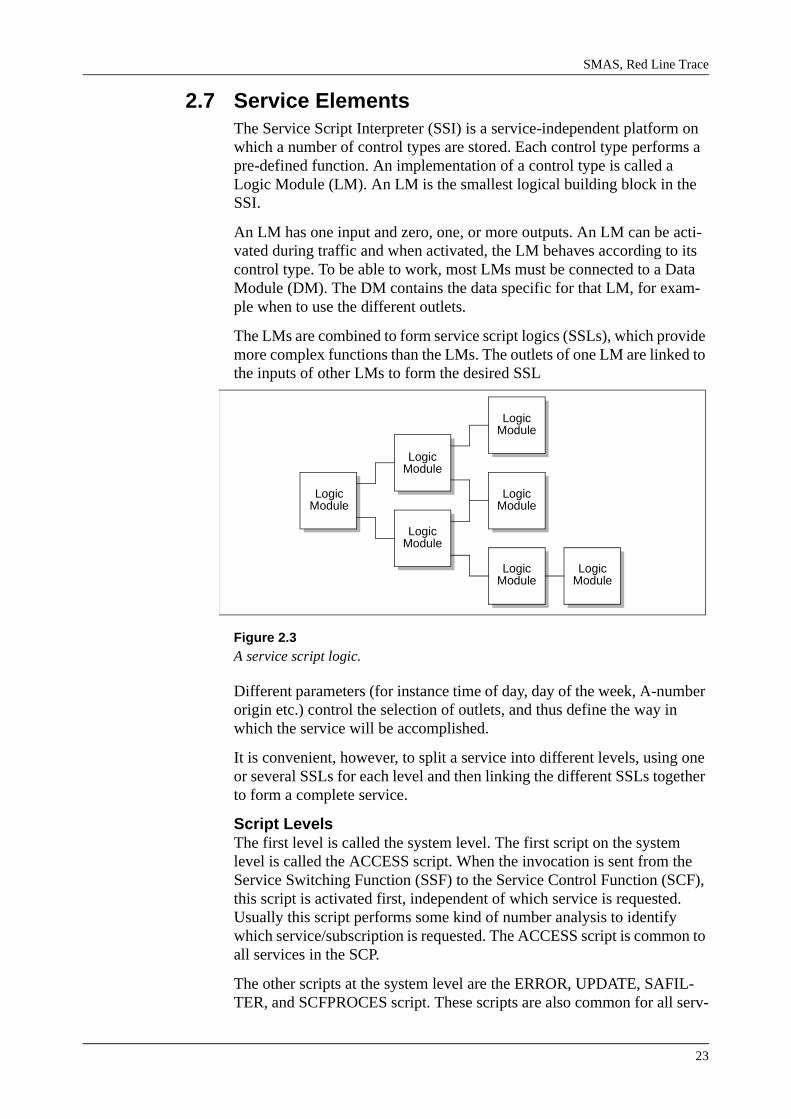
The LMs are combined to form service script logics (SSLs), which provide more complex functions than the LMs. The outlets of one LM are linked to the inputs of other LMs to form the desired SSL
Figure 2.3A service script logic.
Different parameters (for instance time of day, day of the week, A-number origin etc.) control the selection of outlets, and thus define the way in which the service will be accomplished.
It is convenient, however, to split a service into different levels, using one or several SSLs for each level and then linking the different SSLs together to form a complete service.
Script LevelsThe first level is called the system level. The first script on the system level is called the ACCESS script. When the invocation is sent from the Service Switching Function (SSF) to the Service Control Function (SCF), this script is activated first, independent of which service is requested. Usually this script performs some kind of number analysis to identify which service/subscription is requested. The ACCESS script is common to all services in the SCP.
The other scripts at the system level are the ERROR, UPDATE, SAFIL-TER, and SCFPROCES script. These scripts are also common for all serv-
LogicModule
LogicModule
LogicModule
LogicModule
LogicModule
LogicModule
LogicModule

IN 2.3 Service Testing Course
24
ices in the SCP. The ERROR script is automatically activated when a fault occurs during the interpretation of a service. The UPDATE script is acti-vated when an update event, due to for example congestion control, is received from the SSP. The SAFILTER script is used for receiving SSF response in the FILTER control type, and the SCFPROCES script is used when creating a new process in the SCF.
Scripts intended for a specific group or category of services/subscriptions are called group scripts. A group script is common for all subscribers to a specific service. However, it is possible to connect data modules (cus-tomer data) to this script, which allows modification according to each subscriber request. This level is called the service level.
On the service level there is also a script called Customer Control (CC) script. This script may be used as a support script when customer data changes via DTMF against data residing in an SCP shall be performed. To be able to change customer data residing in an SDP via DTMF, no CC script is required.
The third level, called the subscriber-specific level, contains scripts intended for a specific service subscriber. A unique subscriber-specific script is created for each subscriber if the service includes subscriber-spe-cific scripts. It is possible to modify the data modules in the subscriber-specific script according to each subscriber request.
Figure 2.4Service Script Levels.
GROUP SCRIPT SUBSCRIBER-
SYSTEM LEVEL
ACCESS SCRIPT
ERROR SCRIPT
SPECIFIC SCRIPT
SERVICE LEVELSUBSCRIBER-
SPECIFIC LEVEL
UPDATE SCRIPT
CC SCRIPT
SDP Data

SMAS, Red Line Trace
25
In addition to the different levels described above, the service can be designed to use an external database (SDP) for storage and/or retrieval of information. To be able to access an SDP, the scripts must contain specific Control Types. Those make it possible to read from and/or write to the SDP.
A service can contain only group scripts, only subscriber-specific scripts or combinations of both. The order between the different kinds of scripts is not relevant.
The functions of the different SCE / SMS interfaces and the usual design and administration procedures are described in more detail in the follow-ing modules.
Each SCE / SMS sales object also has its own SCE / SMS User Guide description, where each interface is described in great detail.
IN 2.3 Service Testing Course
26
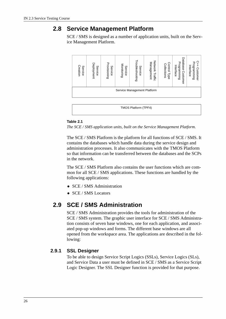
2.8 Service Management PlatformSCE / SMS is designed as a number of application units, built on the Serv-ice Management Platform.
Table 2.1 The SCE / SMS application units, built on the Service Management Platform.
The SCE / SMS Platform is the platform for all functions of SCE / SMS. It contains the databases which handle data during the service design and administration processes. It also communicates with the TMOS Platform so that information can be transferred between the databases and the SCPs in the network.
The SCE / SMS Platform also contains the user functions which are com-mon for all SCE / SMS applications. These functions are handled by the following applications:
• SCE / SMS Administration
• SCE / SMS Locators
2.9 SCE / SMS AdministrationSCE / SMS Administration provides the tools for administration of the SCE / SMS system. The graphic user interface for SCE / SMS Administra-tion consists of seven base windows, one for each application, and associ-ated pop-up windows and forms. The different base windows are all opened from the workspace area. The applications are described in the fol-lowing:
2.9.1 SSL DesignerTo be able to design Service Script Logics (SSLs), Service Logics (SLs), and Service Data a user must be defined in SCE / SMS as a Service Script Logic Designer. The SSL Designer function is provided for that purpose.
Service
Creation
Service
Deploym
ent
Service
Provisioning
Service
Monitoring
Service
Troubleshooting
Netw
ork Traffic
Managem
ent
Control Type
Collections
Database C
ustomer
Program
ming
Interface
C+
+ C
ustomer
Program
ming
Interface
Service Management Platform
TMOS Platform (TPF4)

SMAS, Red Line Trace
27
2.9.2 Network Element AdministrationThe graphic user interface for Network Element Administration allows the user to list, define, delete, and modify Network Elements (NEs). Two NEs of the same type can be defined as being mated. It is also possible to view details about an NE.
2.9.3 Event Log ManagerThe purpose of the event log is to maintain a history of system activities that directly or indirectly affect subscriber services. The events logged may be used for monitoring, troubleshooting, and auditing an SCE / SMS system.
2.9.4 Data Translation Editor The Data Translation function allows the user to add, delete and update site specific meanings of certain text parameters, for example routing information and error values.
2.9.5 NE Request QueueThe NE Request Queue is a function used for communicating with a Net-work Element (NE). A request, for example an installation or a removal (of a service, subscription or global data module), an audit, or a data mod-ule update, is always executed as a background process. A request may be specified for immediate execution or scheduled for later execution. Two forms are provided to be able to see the NE Request Queue and the status for different requests:
• The NE Request Queue Manager, in which the user can view entries inthe queue. Request parameters can be displayed for each entry.
• The NE Request Queue Notifier which spontaneously displays any change in the queue that the user has ordered.
2.10 SCE / SMS LocatorsThese SCE / SMS functions provide the tools for locating different objects defined in SCE / SMS. The Locators can be activated from the base win-dow of different applications to locate applicable objects. Note though that the Locators can not be activated from any of the applications in the SCE application unit Service Creation.
SCE / SMS Locators are divided into three functions:
5. Service/Subscription Locator
The Service/Subscription Locator provides a graphic interface for locating service/subscription elements defined in SCE / SMS. The following ele-ments can be located with the Service/Subscription Locator:
IN 2.3 Service Testing Course
28
• SCPs
• Services
• Subscribers
• Subscriptions, that is, Telephone Numbers
• SSLs
6. Global Data Module Locator
The Global Data Module Locator provides a graphic interface for locating Global Data Module (GDM) elements defined in SCE / SMS. The follow-ing elements can be located with the Global Data Module Locator:
• SCPs
• Control Types
• Global Data Modules
7. SDP Locator
The SDP Locator provides a graphic interface for locating SDP elements defined in SCE / SMS. The following elements can be located with the SDP Locator:
• SDPs
• SDP Applications

SMAS, Red Line Trace
29
2.11 Service CreationService Creation is the activity of creating the logic of a service and then to add service data to the logic. The logic is network dependent, that is, the logic is designed to work with specific network element types and the desired network element type is chosen by selecting a Control Type Col-lection (CTC) when the logic is designed.
The logic of a new service is formed by one or more Service Script Logics (SSLs). An SSL is constructed by linking Logic Modules (LMs) together and specifying attributes etc. The combination of SSLs then makes up the Service Logic (SL).
Figure 2.5LMs combined to form an SSL.
When the design process has been completed, SCE automatically checks the SL for logical inconsistencies. Completed SSLs and SLs are stored in the service logic library and can easily be recalled, and modified to meet new requirements from other customers.
Service data can be entered to the Service Logic by the service operator or the subscriber (Customer Control). Service data consists of local data, cus-tomer data, global data, or a combination of these. Local data and cus-tomer data are connected directly with the Service Logic. Global data must be defined before it can be connected with the logic. That is why it has its own SCE / SMS application.
Service Creation also includes a possibility to transfer SSLs, SLs, services, and global data modules between different SCE / SMS systems.
Service Creation is divided into five applications:
1. Service Script Logic Definition
The Service Script Logic Definition application is used to design the SSLs. To be able to create SSLs, the operator must be registered as a Service Logic Designer.
When an SSL is to be created, the user must start with selecting a Control Type Collection (CTC) or just use the default one. A CTC is a collection

IN 2.3 Service Testing Course
30
of Control Types specific to a type of network element, a particular net-work protocol, or any other grouping. The design of an SSL is accom-plished by creating a logic module graph, that is, choosing control types, defining their parameters, such as mode, input register and number of out-lets and then connecting them with one another.
An LM is defined by selecting a control type from a palette positioning it in the working area and setting a number of parameters.
Figure 2.6The control types palette.
The SSLs are stored in the service logic library as private to the designer. Once the design is complete, the designer can change the status of the SSL to public, which means that the SSL is available to other designers for fur-ther use in Service Logic design.
Service Script Logic Definition also includes functions for editing and viewing existing SSLs.
2. Service Logic Administration
The Service Logic Administration application is used to design SLs.
An SL is created by selecting a set of public SSLs from the service logic library. The designer must mark the SSLs as being group SSLs or sub-scriber-specific SSLs. A group SSL must also be marked as an ordinary SSL or a Customer Control (CC) SSL. One SSL must also be marked as the first one on each level.
During the creation of an SL, the SL is private to the designer. The designer can then change the SL to public, which means that it is available for use in a service.

SMAS, Red Line Trace
31
Service Logic Administration also includes functions for editing and view-ing existing SLs.
Figure 2.7Create an SL by choosing public SSLs from the service logic library.
3. Global Data Administration
Global Data Administration is an application used to define Global Data Modules (GDMs). GDMs are data modules which are associated with a particular control type, and which all service designers can connect with LMs derived from that control type.
A GDM is specified by defining a GDM name, selecting a control type, a CTC, and specifying number of outlets. If specifying a CCPROC GDM, the control type to be customer controlled must also be entered. Then the data values are added, and the GDM is stored in the service library in SCE.
Global Data Administration also offers the possibilities to modify a GDM, copy a GDM, rename a GDM, or delete a GDM.
To be able to install/remove GDMs in/from an SCP, or to work with “Only Installed” GDMs the Global Data Administration application within the Service Deployment application unit must be used.
4. Service Definition
A service is defined in SCE by selecting a public SL from the service logic library and adding data to all the SSLs in that SL. The data can be either local to the service, local to the subscriber (customer data), or global. When developing a group of services, it is possible to share customer data between them (that is, shared SC). It is also possible to connect a DM in an SSL to Customer Control (CC), which means a subscriber is permitted to change part of his own data via a DTMF telephone. When data has been added, the service is stored in the service library.
Service Definition also offers the possibilities to copy a service, to validate a service, to share data between two services, or to delete a service. The copy function is important when creating new service versions to already existing subscriptions.
Service Logic Administration Service Logic Library
Freephonescript 1 Sep 26 1992
Validationscript_2 Sep 30 1992 2:23:12PM Group
1:23:18PM First Group

IN 2.3 Service Testing Course
32
5. Service Transfer
The Service Transfer application is the tool for transferring services (serv-ice logic and service data) to and from an SCE / SMS system by means of the UNIX file system. It is also possible to copy the UNIX file to tape.
Figure 2.8Service Logic Transfer.
This application is used for transferring services designed at one service management centre to another service management centre. The application makes it possible for the service provider to centralize all service creation.
Tape
Disk
Files
Service
Library
UNIX
SCE / SMS Platform
Logic

SMAS, Red Line Trace
33
2.12 Service DeploymentService Deployment provides the tools for administering services and glo-bal data in the SCPs, including to create and install new versions of serv-ices. There is an application for defining a new SCP as a mate to an already existing SCP within an SMS system.
Service Deployment also includes a possibility to transfer services and global data modules between different SCE / SMS systems, and a tool for sending test queries, that is, to simulate the SSF-SCF interface.
Service Deployment is divided into six applications:
1. Global Data Administration
Global Data Administration is an application used to define Global Data Modules (GDMs). GDMs are data modules which are associated with a particular control type, and which all service designers can connect with LMs derived from that control type.
A GDM is specified by defining a GDM name, selecting a control type, a CTC, and specifying number of outlets. If specifying a CCPROC GDM, the control type to be customer controlled must also be entered. Then the data values are added, and the GDM is stored in the service library in SCE.
A GDM is installed by selecting a GDM from the service library and an SCP. The GDM can be installed in the SCP immediately or scheduled for future installation by specifying a time. The NE Request Queue facility is used in both cases, which means that the installation will take place as a background process.
Global Data Administration also offers the possibilities to remove a GDM from an SCP, modify a GDM, copy a GDM, rename a GDM, or delete a GDM.
2. Service Deployment
Service Deployment is used to install services. When installing a service into an SCP, a service must be selected from the service library and an SCP must be specified. The service can be installed immediately or sched-uled for a future installation by specifying a time. The NE Request Queue facility is used in both cases, which means that the installation will take place as a background process.
Service Deployment contains facilities to activate a service, deactivate a service or remove a service from an SCP.
Service Deployment offers the possibility to set up new service versions to already existing subscriptions, to switch service versions for subscriptions or to remove service versions not longer wanted. This is done without los-ing any subscriber-specific data already created and installed.

IN 2.3 Service Testing Course
34
Service Deployment also includes a function to migrate services built on the Control Type Collections IN2.0 and IN2.1 to services using the Con-trol Type Collections in an IN2.2 SCP, either IN2.1+, CS1, or CS1+.
3. Installed Service Modification
This application enables the user to change data for a service directly in the SCP. The application makes visible data structures in the SCP which are hidden by other applications, such as Service Administrator (SA), Service Customer (SC), and OP/NOP areas.
With this application it is possible to, for example, modify data in an installed service/subscription, activate and de-activate a service, or re-install a service.
This application also makes it possible to install or remove an SSL, inde-pendent of a service or a subscription. The installation of the access, error, and update scripts is done in this way.
4. Query Simulation
Query Simulation is a tool for sending test queries, that is, to simulate the SSF-SCF interface. It allows a user to simulate the query, conversation response, and termination notification sent by an SSF. The query simula-tion is used either when a new service has been created, in order to test its function or for troubleshooting an already existing service or subscription.
For the Control Type Collections CS1, CS1+, CS1G, and CS1-CH, Query Simulation offers a possibility to trace the call. The trace function indi-cates which logic modules are accessed as the call passes through the serv-ice logic.
5. Service Transfer
The Service Transfer application is the tool for transfer services (service logic and service data) to and from an SCE / SMS system by means of the UNIX file system. It is also possible to copy the UNIX file to tape.
Figure 2.9
Tape
Disk
Files
Service
Library
UNIX
SCE / SMS Platform
Logic
SMAS, Red Line Trace
35
Service Logic Transfer.
This application is used for transferring services designed at one service management centre to another service management centre. The application makes it possible for the service provider to centralize all service creation.
6. Mated Pair Introduction
Mated Pair Introduction (SMAAM) is a function for defining a new SCP as a mate to an already existing SCP within an SCE / SMS system. The function copies all installed data from the existing SCP to the mate and then installs the data into the mated SCP. It is implemented as a combina-tion of manual actions and a computer application and has no graphical user interface.

IN 2.3 Service Testing Course
36
2.13 Service Provisioning
Figure 2.10Defining a subscription
Service Provisioning is the activity of defining subscribers and administer-ing subscriptions. The Service Provisioning is divided into four applica-tions:
1. Subscriber Administration
Subscriber Administration is an application whereby the user can define new subscribers, delete old subscribers, and modify data for existing sub-scribers. Some services allow the subscriber to modify the subscriber spe-cific data. This could be done either by Subscriber Control via SCP (Customer Control) or by Subscriber Control via SMS.
Subscriber Control via SMS means that the subscriber has access directly to SMS, via a workstation or a terminal, where the subscriber is able to change the subscriber specific data.
Subscriber Control via SCP means that the subscriber is able to change the subscriber specific data, belonging to the subscriber, via a DTMF tele-phone.
2. Subscription Administration
Subscription Administration is an application for defining subscriptions, that is, a subscriber and an installed service are selected and subscriber-specific data is defined. Each subscription is identified with a unique tele-phone number/SCP. For those subscribers who are allowed to modify part of their own data via a telephone (Subscriber Control via SCP), a CC tele-phone number must also be defined.
SERVICE
SUBSCRIBER
SUBSCRIPTION
SCP
SMAS, Red Line Trace
37
The Subscription Administration application also contains the possibility to install Subscriptions or Customer Control, or both into an SCP; or remove Subscriptions or Customer Control, or both from an SCP; immedi-ately or at a future time. Before installing a Subscriptions or Customer Control, or both, subscriber-specific data should be defined.
3. AdmGroup Administration
The Application is used to define security permissions for any application that uses AdmGroups. Each application has its own forms for administer-ing the permissions depending on the data being managed.
The SMS admgroups are assigned according to a hierarchy of permissions. The ‘smasadm’ user has root access to the system and can view and manipulate all subscriptions, subscribers, admgroups, and other objects.
4. SDP Data Administration
The Service Data Point is a database storage and retrieval system which increases the overall capacity of an Intelligent Network, by allowing data to be shared among different SCPs and SSPs. It provides high speed access to subscriber profile data to other nodes in the Intelligent Network and can also act as a gateway to other systems.
The SDP Data Administration application provides a graphical interface for viewing and manipulating SDP data. There is a possibility to insert new data rows or to modify, view, or delete already inserted data rows in a transaction which is then submitted to an SDP.
5. HLR Administration
The functions in HLR Administration provide interfaces for the following
• Defining and deleting subscribers of HLR subscriptions
• Defining and deleting HLR subscriptions, and connecting them to an HLR
• Manipulating data field permissions and control flags.

IN 2.3 Service Testing Course
38
2.14 Service MonitoringService Monitoring provides applications for managing and monitoring installed services and subscriptions. It also includes applications for col-lecting information from the SCPs, such as statistics and call report infor-mation. Service Monitoring is divided into four applications:
1. Statistics
The measurement of statistics is performed by the SSI-function in the SCP and the Statistics application in SMS provides a user interface where it is possible to specify what to measure, when to start and stop the collection, and present the result.
Statistics are collected on time interval or number of attempts. To be able to collect statistics and present statistics reports the service must include certain DMs or logic.
2. Running Counters
The Running Counters application allows the user to view or reset a run-ning counter in an SCP. A running counter is a counter specific to some of the control types that are updated in real-time in the SCP as the SCP proc-esses its queries. The values of these counters are not continuously sent to the SMS system, and so the database is not always fully updated with this information. Therefore, this application provides the possibility to directly access the SCP to request the current value of these counters or reset them to zero.
3. Call Reports
A call report is a focused study on the signalling between the SCF and the SSF during an IN call. The SSI-function in the SCP monitors the calls and the Call Reports application in SMS provides a user interface where it is possible to specify what information to monitor, when, and present the result.
Call data items to be monitored are call query, call response and call termi-nation information.To be able to collect call data items and send call reports, the service must contain certain DMs or logic.
4. Exception Reports
An Exception Report is a call report which includes a binary error code. The error codes are set by the services or by the SSI itself under certain conditions. An exception report is sent to SMS in the same way as call reports, but may be routed to a specific output device, for example a printer or the system administrator’s mailbox. The error code can, with help of the Data Translation Editor, be translated into a text string before being sent to the output device.

SMAS, Red Line Trace
39
2.15 Service TroubleshootingService Troubleshooting provides applications for auditing and trouble-shooting installed services and subscriptions. Service Troubleshooting is divided into four applications:
1. Audit
The function of audit is to compare data in a Network Element with the corresponding data in the SCE / SMS database or between mated NEs. Audit should be used any time that data in the SCE / SMS database is sus-pected to differ from that in the NE, or when data in mated NEs differ. Audit should also be used as a part of normal NE maintenance.
An audit process is executed as a background process. If an audit has been specified with restricted execution time, it may be started and stopped sev-eral times. This is used to execute large, time-consuming audits, to avoid using overwhelming computing resources.
Each execution of an audit will produce a discrepancy report. A discrep-ancy report showing missing data in the NE can be handled by means of the re-install function in the Installed Service Modification application.
2. Blocking/Deblocking
Blocking/Deblocking is a tool to manually block/deblock a service or sub-scription. Blocking a service or a subscription means to temporarily taking it out of traffic. When a service is blocked, all subscriptions to that service are automatically blocked.
3. Manual Setting
Manual Setting is a tool to manually determine the LM outlet that should be chosen, regardless of the dictates of any attached data module. It is used in combination with Query Simulation to test new services during service creation. The Manual Setting application is not intended for use in traffic.
4. Query Simulation
This application is also included in the Service Deployment sales object.

IN 2.3 Service Testing Course
40
2.16 Network Traffic ManagementThe Network Traffic Management (NTM) application is used to protect the SCP against service traffic overload through congestion control. Con-gestion control can be used to limit call intensity for a specific number or range of numbers, for example all 800 numbers.
Congestion control is mainly defined by:
Duration of ControlThe length of time during which calls are monitored
Allowed Number of CallsThe maximum number of calls allowed per gap interval
Gap IntervalThe time period during which calls are counted
The first call arriving during the duration of control starts the gap interval. Once the maximum number of calls (Allowed number of Calls) has occurred within the specific time frame, or gap interval, all subsequent calls are rejected for the remainder of that gap interval. The first call arriv-ing after the previous gap interval expires begins a new gap interval. This process of counting calls per gap interval continues until the duration of control expires (see the figure below).
Figure 2.11Congestion Control
Allowed noof calls
Gap IntervalRejected calls time
calls
Duration of Control

SMAS, Red Line Trace
41
2.17 Control Type CollectionA Control Type is a function in the Service Script Interpreter (SSI). The SSI contains a number of different Control Types which can be used to define Logic Modules (LMs). The LMs can then be combined to realize the logic function of a service. A combination of LMs form a Service Script Logic (SSL) and one or more SSLs form a Service Logic (SL).
Most of the Control Type functions involve processing of data, for exam-ple, number analysis. For these Control Types, Data Modules (DM) with service data are connected to the LMs in the SSL when a service is defined.
The Control Types are gathered into Collections. There are eight different Control Type Collection depending on what kind of AXE or Unix SCP software the Control Types will support and what kind of services are demanded:
• Control Type Collection IN 2.0
• Control Type Collection IN 2.1
• Control Type Collection US Market
• Control Type Collection IN 2.1+
• Control Type Collection CS1
• Control Type Collection CS1+
• Control Type Collection CS1-CH
• Control Type Collection CS1G
Control Type Collection IN 2.0The Control Type Collection IN 2.0 contains Control Types that makes it possible to work with the SSI.2.0. in AXE.
Control Type Collection IN 2.1The Control Type Collection IN 2.1 contains Control Types that makes it possible to work with the SSI.2.1. in AXE. The following new functional-ity have been introduced in the Control Type Collection IN2.1 compared with Control Type Collection IN2.0.
• Enhancement to congestion control
• Support for ISDN services
• Support for Virtual Private Network
Control Type Collection US MarketThe Control Type Collection US Market functions have been developed to meet customer demands in the North American market for the Advanced Intelligent Network (AIN) products. The following new functionality have been introduced in the Control Type Collection US Market compared with Control Type Collection IN 2.0.

IN 2.3 Service Testing Course
42
• Support for multiple protocols
• Support for communication with other network entities
• Support for virtual directory numbers
The CTC US Market also contains Query Simulation enhancements to support multiple protocols and service script logic tracing.
Control Type Collection IN 2.1+The Control Type Collection IN 2.1+ contains Control Types that makes it possible to work with the SSI.2.2. in AXE. The purpose of this Control Type Collection is to support IN2.1 functionality in the SSI.2.2. The fol-lowing new functionality have been introduced in the Control Type Col-lection IN2.1+ compared with Control Type Collection IN2.1:
• New CC
• New queue functionality
Control Type Collection CS1The Control Type Collection CS1 contains Control Types that makes it possible to work with the SSI.2.2. in AXE. The Control Type Collection CS1 supports development of ETSI CS-1 services.
Control Type Collection CS1+The Control Type Collection CS1+ contains Control Types that makes it possible to work with the SSI.2.2. in AXE. The following new functional-ity have been introduced in the Control Type Collection CS1+ compared with Control Type Collection CS1:
• Leg manipulation
Control Type Collection CS1-CHThe Control Type Collection CS1-CH contains Control Types that makes it possible to work with the SSI.2.2. in AXE.
Control Type Collection CS1GThe Control Type Collection CS1G contains Control Types to support IN2.2 CS1 functionality in Unix SCP-G.

SMAS, Red Line Trace
43
2.18 Database Customer Programming InterfaceThe Database Customer Programming Interface sales object provides an API for accessing the SMS database. It can be used by a service provider to develop new customized user interfaces for the Service Provisioning functions in SMS.
The sales object is intended for programmers with experience and knowl-edge of how to develop application programs and APT-based user inter-faces.
The sales object consists of:
• an SQL interface
• user documentation describing the programming interfaces and how to use the mouse.

IN 2.3 Service Testing Course
44
2.19 C++ Customer Programming InterfaceThe C++ Customer Programming Interface sales object provides an API for accessing the SCE / SMS database via C++. It can be used by a service provider to develop new customized user interfaces for the Service Provi-sioning functions in SMS.
The sales object is intended for programmers with experience and knowl-edge of how to develop application programs and OpenWindows-based user interfaces.
The sales object consists of:
• two C++ class libraries
• user documentation describing the programming interfaces and how to use the mouse.
Note: The TMOS Development Platform (TDP) and a number of third party soft-ware are required for using this interface.
2.19.1 Generic Service Adapter (GSA)Worth mention here is also the Generic Service Adapter (GSA) which is a product closely associated to SCE / SMS but not included in the standard SCE / SMS product.
The GSA supports a Service Provider with tools to design user interfaces for service provisioning. The tool can be used for developing both com-mand line oriented applications, form based applications and remotely based applications accessing the SCE / SMS system through a communi-cation interface (RPC). Note though that the GSA only supports IN serv-ices created by SCE.
The GSA is intended for service designers with appropriate experience and knowledge about the GSA and its associated 4GL tool. The TMOS Development Platform (TDP) is NOT required for using this interface. By means of the 4GL tool, and SYBASE APT Workbench, the user interface can be designed.
The GSA includes three main parts:
• A user interface template used as a development base when designing new user interfaces
• A setup template which is an ordinary textfile which can be changed by any editor, for example, textedit
• An executable which is used in runtime and provides all functionality for Service Provisioning
SMAS, Red Line Trace
45
2.20 Design RulesSome rules to think of when designing services in SCE:
• During Service Creation it is possible for the service designer to choose to use only group scripts, only subscriber-specific scripts, or combina-tions of both group and subscriber-specific scripts in the SL. However, it is recommended that only group scripts are used. Subscriber-specific data should be defined by connecting Customer Data Modules (CDM) to the LMs. Subscriber-specific scripts should be used only if there is a need for subscriber-specific data on LMs that cannot take customer data, or when subscriber-specific global data is needed.
• When Customer Control is used in SCE / SMS, the service is imple-mented as two scripts, one changeable (the “real” script) and one asso-ciated script that performs the change in the changeable script. The best way to enable/disable Customer Control for each subscription in the Subscription Administration application is to create a group SSL marked CC in Service Creation. This SSL should contain CCTRAF LMs for defining how the service change should be performed.
• If a subscription is created without customer data and customer data is later added via the Installed Service Modification application the SC will not automatically be updated in the NRANAX global data module. This must be done manually for all subscriptions.
• The Blocking/Deblocking application requires the use of a NRANAX logic module with global data for the number analysis.
• Use only global data modules for number analysis control types such as NRANA and NRANAX when SMS will enter the number in the DM. Subscriptions cannot be installed in a local NRANAX from SCE. If the service contains customer data, a global NRANAX logic module must be chosen.
• Outlet 2 (the third outlet) on number analysis data modules such as NRANAX is used by SCE as an outlet for blocked subscriptions. It should not be used as the first match outlet.
• Do not use customer data in the access script.
• To be able to create exception reports, the error script must contain a REPORT or SREPORT data module.
• When developing groups of services with shared SC, it is recom-mended that the data model, that is, what data modules that are required, is considered first, and thereafter the service logic is defined,

IN 2.3 Service Testing Course
46
in order to obtain a sound data storage structure.
When using the INM protocol, it is recommended to use output 9 for cus-tomer control, and output 10 for traffic measurements.

SMAS, Red Line Trace
47
2.21 Red-line Trace
2.21.1 Red-line Trace OverviewThe Red-line Trace (RLT) application is a debugging tool for services designed in SMAS. It allows the user to test services locally, before the service is installed in an SCP. This is accomplished by simulating the SCP, the SSP, the SDP, and the INAP or the CS1 protocol. RLT can be used as a demonstration and training tool as well.
The simulation is contained entirely within the SMAS system.
2.22 Execution of Red-line TraceRLT allows the user to specify an uninstalled service or an SCP, provide it with start values and simulate the interaction between the SSP, the SCP, and the SDP.
The SSL is visible at all times of the simulation with a red line showing the execution path step by step. RLT provides a ‘resource’ window for voice prompting and digit collection. It is possible to play audio recordings for the announcements. The simulation can be provided step by step or in a continuous mode and at variable speeds. The layout of the simulation out-put windows can be set before and during simulation.

IN 2.3 Service Testing Course
48
2.22.1 WorkflowThere are two different types of workflows in RLT. The one displayed on the left describes the flow using 2.1, 2.1+, CS1, and CS1+ mode. The one displayed on the right describes the flow using CS1 /w Call Model mode.
Figure 2.122.1, 2.1+, CS1, CS1+ and CS1/w Call Model mode.
Start the Red-line Trace Application
If necessary,specify
parameters
Repeat until the logic is tested
Exit the User Interface
Select Installed/Uninstalled mode
If Installed:Select an SCP
If Uninstalled:Select a Service
Use Step, Next or Continue to move through the logic
Respond to announcement
and digit collection
Send required leg events
Select a Run command
Select Detection Point
Select a Run operation
Repeat until the logic is tested
Exit the User Interface
Select Installed/Uninstalled mode
If Installed:Select an SCP
If Uninstalled:Select a Service
Use Step, Next or Continue to move through the logic
Respond to announcement
and digit collection
Send required leg events
If necessary,specify
parameters
Start the Red-line Trace Application

SMAS, Red Line Trace
49
2.23 Tools for DebuggingRed-line Trace provides several tools to help debug and report problems on a service.
BreakpointsRLT provides three kinds of breakpoints: logic module, tag and operation. A logic module breakpoint will cause the service to stop executing when the breakpoint is reached. A tag breakpoint will cause the service to stop executing when the tag changes. An operation breakpoint will cause the service to stop executing when a particular operation is ready to be proc-essed.
Logic Module TraceAs each logic module is executed, it is highlighted and the outlet taken is shown with a red line. In addition to this graphical display, a log of each module and outlet can be output to the dialogue window. Anything in the dialogue window can be saved to a file or included in a trouble report.
Information like error messages and changed tags can also be placed in the dialogue window.
INAP DialogueThe INAP messages passed between the SCP, SSP, and SDP are output to the dialogue window.
Forced OutletsService logic execution does not have to follow the logic of the service. If you wish to test a certain path in a service, or if a bug in the service needs a temporary work around, any outlet can be forced by clicking the left mouse button on the chosen path corresponding to that outlet. The connec-tion turns blue to indicate that RLT always will take this path.
Goto HereIf you wish to skip over parts of an SSL, you may select ‘Goto Here’ on the logic module where execution should continue. Goto Here can even be used after an error has occurred, preventing the ERROR script from being invoked.
Time AdjustmentServices that use the date and/or time can be thoroughly tested by chang-ing the simulation clock to any value. If your service does something spe-cial on New Years Day, there is no need to wait until January 1 to test the service. Simply change the system clock.
SCP Monitor ListAt any one moment, the SCP can be waiting for several things to happen. It is sometimes difficult to know exactly what the SCP expects. For this

IN 2.3 Service Testing Course
50
reason, RLT allows you to view the SCP’s monitor list, revealing which events are expected, on what leg and with what InvokeID.
Call Instance Data ManipulationThe call instance data, also known as tags, can be viewed and changed at any point during service execution. This can be useful for certain test cases or in situations where a temporary work around is needed in a service.
Multiple Connection ViewsServices that have features like network protection, uniform load distribu-tion, or call queuing cannot be tested with only one call at a time. As many as 10 simultaneous calls may be simulated using RLT by opening addi-tional connection views.
Temporary IR/OR Register ChangesThe IR or OR values can be changed during a simulation. This allows the user to try new IR/OR settings before going through the steps required by SMAS for permanent solutions.

SMAS, Red Line Trace
51
2.24 Red-line Trace ETSI CS1 and CS1+This section describes the RLT base window, the menus and the pop-up windows for handling and executing RLT using the ETSI CS1 and ETSI CS1+ domain.
2.25 Red-line Trace Base WindowA major feature of the base window is the service script logic display where active logic modules are highlighted, and the logic flow is indicated by a red line.
The base window with an example service is shown below:
Figure 2.13Red-line Trace Base Window
The control area includes the following buttons:
File This displays a menu with choices of loading and locating services. It also provides an option to start a new connection view and selecting the protocol used for the simulation.
View This displays a menu with choices for viewing information about the active RLT process.

IN 2.3 Service Testing Course
52
Edit This displays options to edit the simulation clock. It also contains the Properties window options for simulation settings.
Run This displays options available for starting the simulation.
Step This steps the simulation to the next logic module.
Next This executes the simulation until the next SSL.
Continue This steps the simulation ahead until input is required.
Stop This stops a continuous simulation.
Send This sends operations to the SCF.
Error This sends error case operations to the SCF.
Assist This sends one operation or error case to the SCF over an assisting dialogue.
Reset This resets the call instance.
The Mode setting area shows if the chosen service is installed or unin-stalled. The text field depends on the Installed/Uninstalled setting:
Service This is the name of the active service and it is only visible in Uninstalled mode. To change service, use the Service Loader in the File menu.
SCP This shows the name of the active SCP and it is only visible in Installed mode. To change active SCP, type the SCP name, or use the Service/Subscription Locator in the File menu.
The RLT base window includes the following info areas display in ETSI CS1+ mode only:
Assisting Displays the legs in the call which are involved in assisting dialogues. The active options under Assist menu button reflect the state of the selected leg.
The RLT base window includes the following permanent text fields:
Date/Time This shows the current SCF date and time. This is the value used by any date or time sensitive logic in the SCF. The Clock option from the Edit menu allows you to change the current date and time.
SA This is the name of the active SA.
SSL This is the name of the active SSL.
SC This is the active Service Customer name.
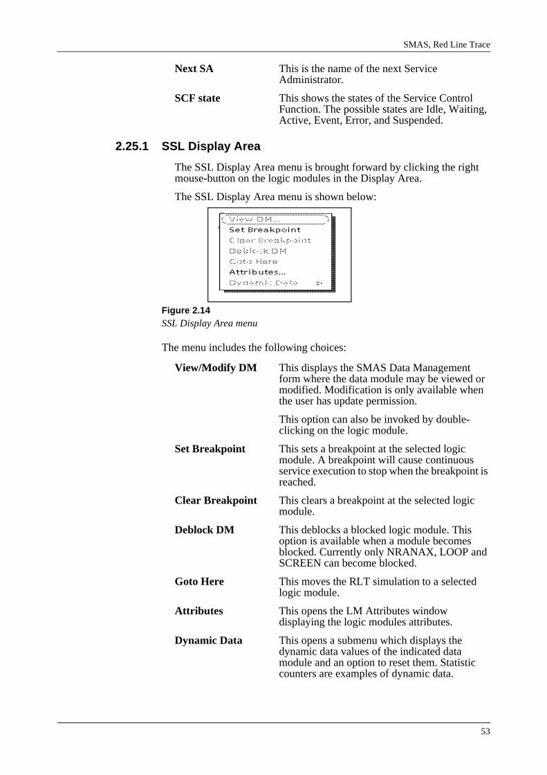
SMAS, Red Line Trace
53
Next SA This is the name of the next Service Administrator.
SCF state This shows the states of the Service Control Function. The possible states are Idle, Waiting, Active, Event, Error, and Suspended.
2.25.1 SSL Display Area
The SSL Display Area menu is brought forward by clicking the right mouse-button on the logic modules in the Display Area.
The SSL Display Area menu is shown below:
Figure 2.14SSL Display Area menu
The menu includes the following choices:
View/Modify DM This displays the SMAS Data Management form where the data module may be viewed or modified. Modification is only available when the user has update permission.
This option can also be invoked by double-clicking on the logic module.
Set Breakpoint This sets a breakpoint at the selected logic module. A breakpoint will cause continuous service execution to stop when the breakpoint is reached.
Clear Breakpoint This clears a breakpoint at the selected logic module.
Deblock DM This deblocks a blocked logic module. This option is available when a module becomes blocked. Currently only NRANAX, LOOP and SCREEN can become blocked.
Goto Here This moves the RLT simulation to a selected logic module.
Attributes This opens the LM Attributes window displaying the logic modules attributes.
Dynamic Data This opens a submenu which displays the dynamic data values of the indicated data module and an option to reset them. Statistic counters are examples of dynamic data.
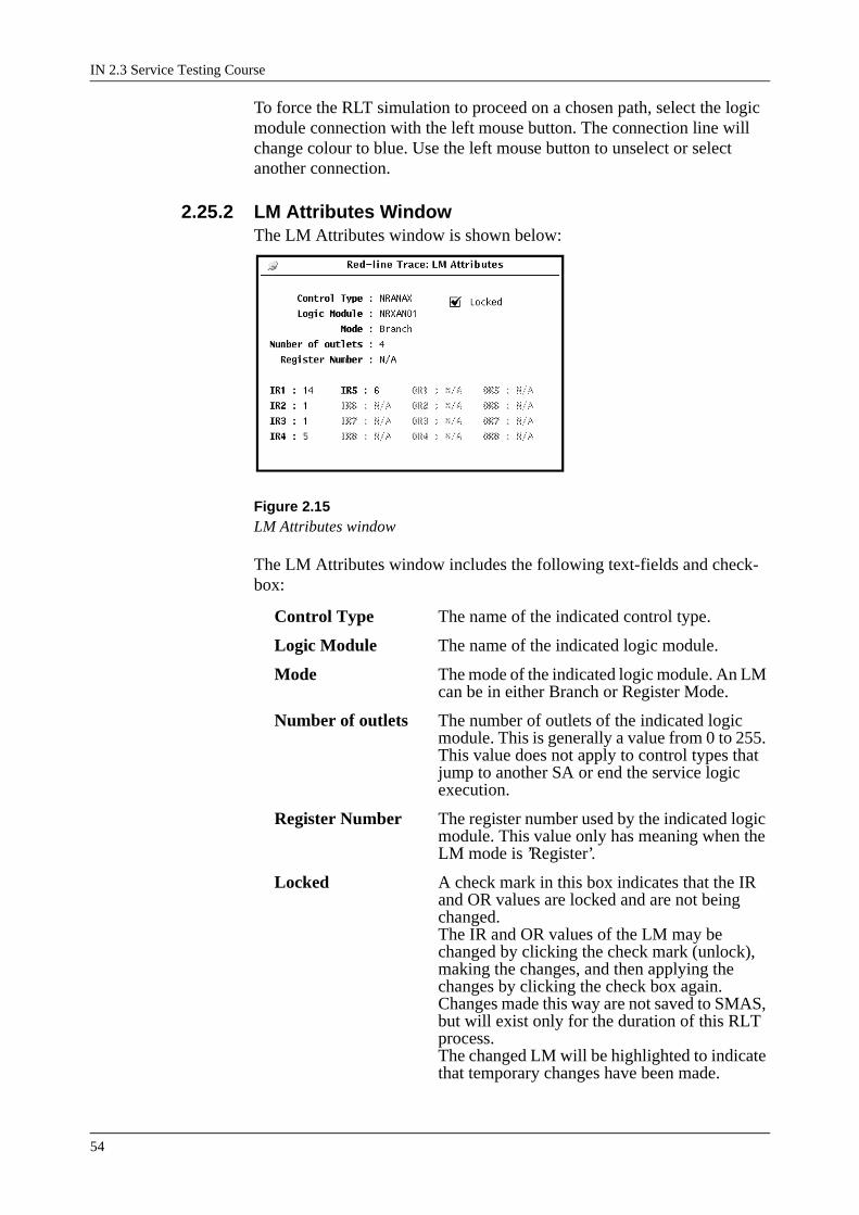
IN 2.3 Service Testing Course
54
To force the RLT simulation to proceed on a chosen path, select the logic module connection with the left mouse button. The connection line will change colour to blue. Use the left mouse button to unselect or select another connection.
2.25.2 LM Attributes WindowThe LM Attributes window is shown below:
Figure 2.15LM Attributes window
The LM Attributes window includes the following text-fields and check-box:
Control Type The name of the indicated control type.
Logic Module The name of the indicated logic module.
Mode The mode of the indicated logic module. An LM can be in either Branch or Register Mode.
Number of outlets The number of outlets of the indicated logic module. This is generally a value from 0 to 255. This value does not apply to control types that jump to another SA or end the service logic execution.
Register Number The register number used by the indicated logic module. This value only has meaning when the LM mode is ’Register’.
Locked A check mark in this box indicates that the IR and OR values are locked and are not being changed.The IR and OR values of the LM may be changed by clicking the check mark (unlock), making the changes, and then applying the changes by clicking the check box again.Changes made this way are not saved to SMAS, but will exist only for the duration of this RLT process. The changed LM will be highlighted to indicate that temporary changes have been made.

SMAS, Red Line Trace
55
Revert This button appears when the LM attribute panel has been unlocked. It may be used to restore an LM to its original IR and OR values.

IN 2.3 Service Testing Course
56
IR and OR When the LM window is "unlocked" the IR and OR register values can be modified. Any value from 0 to 65535 may be entered.
Highlighted LMThe highlighting syntaxes are setup as follows:
blue Indicates that the LM is selected.
yellow Indicates that the OR or IR values of the LM have been changed.
green Indicates that the OR or IR values of the LM have been changed and that the LM is selected.

SMAS, Red Line Trace
57
2.26 File MenuThe File menu includes choices for loading and locating new services. It contains the following items:
Services Opens the Service Loader window where you can select from services in the SMAS system. This is used in the Uninstalled mode. LocateOpens the Service/Subscription Locator. The Locator helps you to find SCPs, Services, Subscribers, and Subscriptions. This is used in the Installed mode.
New Call View Opens a new base window connection view containing the same service.
E-INAP 2.1+ Changes the current domain to E-INAP 2.1+.
E-INAP 2.1 Changes the current domain to E-INAP 2.1.
ETSI CS1 Changes the current domain to ETSI CS1.
ETSI CS1 w/ Call ModelChanges the current domain to ETSI CS1 w/ Call Model.
ETSI CS1+ Changes the current domain to ETSI CS1+.
2.26.1 Service Loader WindowThe Service Loader window contains a list of existing services. The win-dow is shown below:
Figure 2.16Service Loader Window
Select the desired service from the service list, then choose the starting SSL from the SSL list. Select Accept when finished.
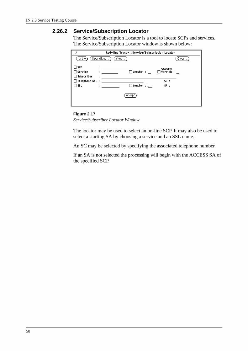
IN 2.3 Service Testing Course
58
2.26.2 Service/Subscription LocatorThe Service/Subscription Locator is a tool to locate SCPs and services. The Service/Subscription Locator window is shown below:
Figure 2.17Service/Subscriber Locator Window
The locator may be used to select an on-line SCP. It may also be used to select a starting SA by choosing a service and an SSL name.
An SC may be selected by specifying the associated telephone number.
If an SA is not selected the processing will begin with the ACCESS SA of the specified SCP.

SMAS, Red Line Trace
59
2.27 View MenuThe View menu contains the following items:
Tags Provides a window with current call instance data. The data may be manipulated from this window.
Dialogue Shows the complete INAP dialogue between the SSF and the SCF and between the SCF and the SDF.
Monitor List Shows the SCF’s monitor list.
Labels This displays a menu with choices for labelling the logic modules in the service logic display.
NPROCES List Shows a window where you may start a new SCF process from a queued list of processes provided by the NPROCES control type.
2.27.1 Tag Values WindowThe Tag Values window shows the call instance data. It is possible to see if the tags have changed from one step to the next. An asterisk appears next to the most recently changed tags. The Tag Values window is shown below:
Figure 2.18Tag Values Window
The Tag Values window includes the following:
Find Includes options to search for a string forward and backwards.

IN 2.3 Service Testing Course
60
Save This menu enables you to save the current tag values in one of five slots. The tag values can be reloaded later using the Load menu or the Auto-load feature. An asterisk (*) next to the slot name on the menu indicates the slot is used. Saving into a used slot will overwrite its contents. A slot can be cleared by selecting save when there are no tags in the tag buffer.
Load This menu enables you to load previously saved tags into the tag buffer from one of five slots. The slot name on the menu is enabled when it contains at least one tag.
Auto-load Tags can be automatically loaded from a particular slot each time service execution begins. It is possible to select None (which disables Auto-load), or one of the slots created from the Save menu. When Auto-clear is activated, the tag buffer will be emptied before auto loading the tags. This ensures a known starting point each time service execution begins.
Tag Displays the name of the selected Tag.
This sets a tag breakpoint. A tag breakpoint will cause continuous service execution to stop when the tag with a breakpoint is changed.
This clears a tag breakpoint.
Auto-clear When Auto-clear is checked (default), all tag values are cleared each time the simulation is run. If this option is not checked, the tag values will remain when the simulation is restarted. This is useful when it is desired to edit tag values before running the service.
Value Displays the value of the Tag.
Set This sets the value of a selected tag.
Delete This deletes a tag, which has been selected.
Delete All This deletes all tags.
The Tag Values window pane contains a list of current tags. The list includes four columns:
KoX This displays the Kind-of-Number, Kind-of -Variable, Kind-of-LongInteger, Kind-of-String of the Tag.
Tag Name This displays the mnemonic name of the Tag.
Buf This displays which kind of Buffer is used. There are four different Buffers: R-Response, Q-Query, T-Temporary and E-Event.

SMAS, Red Line Trace
61
Value This displays the current value of the Tag.
2.27.2 SSF/SCF Dialogue WindowThe SSF/SCF Dialogue window is shown below:
Figure 2.19SSF/SCF Dialogue Window
By default, the SSF/SCF Dialogue window shows the INAP messages passed to and from the SCF and SSF. An option on the properties window allows you to select other information which can also be shown in the dia-logue window. Any combination of the following may be selected:
Dialogue INAP messages between SCF and SSF.
Changed Tags A list of tags that have changed after the execution of a logic module.
Logic Module The SA name, the SA side (OP or NOP), the SSL name and version, the outlet used, and the logic module name are listed as each logic module is executed.
Error Text Messages from the SCF which are normally only displayed in the window footer are also placed in the dialogue window.
In the left column in the SSF/SCF Dialogue window a character displays the type of the dialogue: I-Initial, A-Assisting, N-Non call, S-SDP/SCF dialogue.
The contents of the dialogue window may be saved to a file or printed for future reference.

IN 2.3 Service Testing Course
62
2.27.3 SCF Monitor List WindowThe SCF Monitor List window is shown below:
Figure 2.20SCF Monitor List window
The SCF Monitor List includes the following columns:
Prio This displays the priority of the monitor request. When several requests for the same event have been made, the priority will decide in which the order that the event is distributed to each requester. Requests with a priority of 0 will get the event first, requests with a priority of 15 will get the event last.
LM Name This displays the name of the Logic Module that requested the event.
SA Name This displays the name of the Service Administrator that contains the requesting Logic Module.
SC Name This displays the name of the Service Customer that was in use when the monitor request was posted.
INVK The invoke id that the monitor request is associated with.
LEG The Leg shows which leg is being monitored.
EVNT This displays the type of event. Possible events are:BCSMErrorEventNotificationChargingApplyChargingReportCallInformationReportReturnResultPromptCollect SpecializedResourceReportInternalErrorLevel2

SMAS, Red Line Trace
63
BCSM When the event is BCSM, this column shows the mask for the monitored BCSM events. Use the right mousebutton to display the mask values. The events possible are: Alerting (CS1+)AnswerNo AnswerDisconnectRe-answer (CS1+)MidcallAbandonSuspended (CS1+)Route Select FailureCalled Party BusyCalled Party Not Reachable (CS1+)Collect InformationAnalyzed Information
Mode This displays the mode of the event. There are three different modes: Notify & Continue, Interrupted, and Transparent.
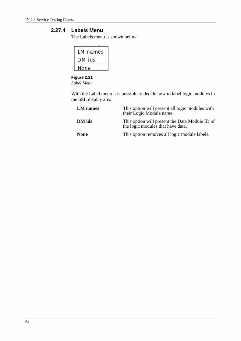
IN 2.3 Service Testing Course
64
2.27.4 Labels MenuThe Labels menu is shown below:
Figure 2.21Label Menu
With the Label menu it is possible to decide how to label logic modules in the SSL display area.
LM names This option will present all logic modules with their Logic Module name.
DM ids This option will present the Data Module ID of the logic modules that have data.
None This option removes all logic module labels.

SMAS, Red Line Trace
65
2.28 Edit MenuThe Edit menu contains the following items:
Clock This displays the Set Clock window which makes it possible to change the simulation time.
Properties This displays a window where properties of the simulation may be set. Properties such as simulation speed, announcement settings and output design may be specified.
2.28.1 Set Clock WindowThe Set Clock window is shown below:
Figure 2.22Set Clock window
It allows the user to manipulate the clock in order to test different dates and times in the logic. Apply is used to accept the new time. Reset will cause the simulation to revert to the current date and time.
2.28.2 Properties WindowThe Properties window is shown below:

IN 2.3 Service Testing Course
66
Figure 2.23Properties Window
The window includes the following permanent textfields:
Execution Speed This slider sets the speed of the simulation when running in continuous mode.
NRANAx Search MethodIndexed or Scanned,
CCTRAF Directive The CCTRAF control type is used to update data modules in a service. There are two options, Pretend to Change DB and Really change DB.
Dialogue Window There are five different settings for the Dialogue Window. Dialogue, Changed Tags, Logic Modules, Error Text and Announcement Text.
Maximum Jumps This makes it possible for the user to change the value RLT uses for maximum number of jumps to reflect the actual limit set by the SCF.
Maximum Gosub DepthThis changes the value used for maximum gosub depth.
Play Announcement This is not used in ETSI CS1/CS1+ mode.
Announcement Path This is not used in ETSI CS1/CS1+ mode.
Parts Path This is not used in ETSI CS1/CS1+ mode.
Effects Path This is not used in ETSI CS1/CS1+ mode.
Announcement Text FileThis is not used in ETSI CS1 mode.
SSRDWR Configuration FileThis is not used in ETSI CS1 mode.
Show SDF Window Always - Shows the SDF window every time an Update or Retrieve operation is sent.
As Needed - Shows the SDF window when an Update or Retrieve operation is sent and an operation break point has been set, or when an SDP has not been identified.
Number Analysis Search Method
The control type NRANAX may search the SMAS database by either scanning the table, or by using the table’s index. Each method has differ-ent characteristics.
Indexed Search Method
The indexed search method is faster than the scanned method when searching large number analysis tables. The best performance, using this

SMAS, Red Line Trace
67
method, will be found when a number analysis table has about 5000 rows or more.
This method has one major disadvantage: Table entries with either * or # in the key will not be found using this method. The only way around this is to use the Scanned search method, or to always store ‘B’ for * and ‘C’ for #.
Scanned Search Method
This method works well with small number analysis tables (under 5000 rows). This method will also find * and # if they are in the table.
CCTRAF Directive
The CCTRAF control type is used to update data modules in a service. This provides the service functionality called customer control. This prop-erty allows the user to decide if CCTRAF should really change the data (as it would in the SCP), or if it should only pretend to change the data.
Pretend to Change DB
When this option is selected, the CCTRAF logic module will go through the entire procedure of locating the DM to change, locating the change procedure (CCPROC), sending announcements (if any), etc. It will not actually cause any data to be changed.
This is the default mode for the CCTRAF Directive.
Really Change DB
In this mode, CCTRAF will go through all the normal steps, including a change to the database. If an uninstalled service is being tested, then only the SMAS database will be changed. If the service and service data is installed, then a request for a change will be placed on the SCP request queue.
This option cannot be selected if the RLT user does not have ‘update’ priv-ileges.
Dialogue WindowBy default, the Dialogue window shows the INAP messages passed to and from the SCF and SSF. This option on the properties window will allow you to select other information which can also be shown in the dialogue window. Any combination of the following may be selected:
Dialogue
INAP messages between SSF and SCF are shown.
Changed Tags
A list of tags that have changed after the execution of a logic module is shown. Both the tag name and its new value are included.

IN 2.3 Service Testing Course
68
Logic Module
The SA name, the SA side (OP or NOP), the SSL name and version, the outlet used, and the logic module name are listed as each logic module is executed.
Error Text
Messages from the SCF which are normally only displayed in the call view window footer are also placed in the dialogue window.
Annc Text
The text shown on the Resource window is also added to the dialogue win-dow.
These five items allow you to log detailed information surrounding the execution of a service. The contents of the dialogue window may be saved to a file or printed for future reference.
Maximum Jumps
The maximum number of jumps from one SA to another is limited by the SCF. This limit is configurable at the time the SCF dump is built. There-fore, RLT allows you to change the value it uses for maximum number of jumps to reflect the actual limit set by your SCF.
The default value for the jump limit is 8. This is the value typically used in most SCF builds. You should not adjust this value unless you are certain your target SCF has a different limit. Using an inaccurate value will mean that RLT will fail to simulate how your service will execute on the target SCF.
Maximum Gosub Depth
The maximum gosub depth is the depth that a subroutine may be nested. Like the jump limit, this limit is configurable at the time the SCF dump is built. RLT allows you to change the value it uses for the maximum gosub depth.
The default for the gosub depth limit is 3. This is the value typically used in most SCF builds. You should not adjust this values unless you are cer-tain your target SCF has a different limit. Using an inaccurate value will mean that RLT will fail to simulate how your service will execute on the target SCF.
Update Permission
It can be said that RLT will never change the database, because it only reads data and never writes. This assures that a novice cannot accidentally damage a working service.

SMAS, Red Line Trace
69
However, with the implementation of CCTRAF, it is possible that RLT will write changes to data in SMAS. To assure only knowledgeable users attempt these operations, a permission file must exist which gives users update permission. Only users with update permission may modify data using RLT.
The permission file is called .rltupdates.
The permission file must exist in the subdirectory pointed to by the envi-ronment variable TMOSHOME. This is usually /opt/tmos.
The file is a list of users who have ‘update permission’. The SMAS or TMOS administrator can create the file in the following way:
cd $TMOSHOME
vi .rltupdates
List user ids of people with update permission, one per line:
etxtidw
etxgroh
etc...If the file contains the word ‘all’ on a line by itself, then all users will have update permission.
This file should have read permission by all SMAS users. Write permis-sion for this file should be disabled except for the system administrator. This can be done with the following command:
chmod 644 .rltupdates

IN 2.3 Service Testing Course
70
2.29 Run MenuThe Run menu includes the following items:
InitialDp Start the service by sending the SCF an InitialDP operation. A subwindow opens where all parameters may be specified.
ServiceFilteringResponseStart the service by sending the SCF a ServiceFilteringResponse operation.A subwindow opens where all parameters may be specified.
NPROCES List Shows a window where you may start a new SCF process from a queued list of processes provided by the NPROCES control type.
Run Start the service without sending any initial operation to the SCF.
InitialDp WindowThe InitialDp window is shown below:
Figure 2.24InitialDP window
Shows a window where you may invoke an InitialDp operation toward the SCF. This operation initiates dialogue between the SSF and SCF.
The InitalDp window displays the parameters that are possible with the activate operation. Mandatory parameters are indicated with an (m) to the right of the name.

SMAS, Red Line Trace
71
Parameters which represent a choice are indicated with the word CHOICE beside their name. Choice parameters may have only one of their subpa-rameters sent. If you supply a value for more than one choice subparame-ter, only the last one is used.Integer values are assumed to be decimal unless preceded by H’ or 0x. Numbers with frames may be indicated by specifying the frame first, fol-lowed by the telephone number. The character & can be used to as a sepa-rator.
The InitialDp subpanel and operation panel displays the following icons:
Selecting this button will display all subparameters so that their values can be modified.
Selecting this button will remove all subparameters from view after they have been displayed.
Selecting this button will display the subparameters of the associated parameter so that their values may be modified.After the subparameters have been displayed and/or modified, they can be removed from view by selecting this button again.
Selecting this button will expand the parameter so that you may view or set the subparameters. Select this button again to collapse the parameter.
The InitialDp window contains the following input fields:
serviceKey Number information that can be used to address the correct application or SSL within the SCF.
calledPartyNumber Information used as routing address at invocation of an IN-service. It is usually a number (IN-service access number) dialled by a calling party to request an IN-service.
callingPartyNumber Information used to identify the calling party. It is a number that can be applied as routing address, for example for call back services.
callingPartyCategory Information sent in forward direction in a call indicating the category of the calling party, for example ordinary subscriber, data call, payphone.
cgEncountered This parameter indicates that the related call has passed call gaping, indicating one or more gapCriteria was passed.
ipsspCapabilities This parameter is sent by the assisting or hand-off SSP to indicate which SRF resources are supported within the SSP. This parameter is applicable to this operation only in the physical scenarios corresponding to assist with relay or

IN 2.3 Service Testing Course
72
hand-off. The use of this parameter is network operator dependant.
locationNumber Specifies the location number of a base station in the mobile network.
originalCalledPartyIdThis parameter carries the dialled digits if the call has met callforwarding on route to the SSP or is forwarded by the SCP.
extensions This parameter allows for network operator specific extensions.
highLayerCompatibilityThis parameter indicates the type of the high layer compatibility, which will be used to determine the ISDN-teleservice of a connected ISDN terminal.
serviceInteractionIndicatorsThis parameter contains indicators used for control of the network based services at the originating exchange and the destination exchange and for providing call control information to the SSP.
additionalCallingPartyNumThis is an additional calling party number, for example a private number.
forwardCallIndicatorsThis parameter indicates if the call shall be treated as a national or an international call. It also indicates the signalling capabilities of the succeeding network connection. The network access capabilities do not indicate the terminal type. For example, an ISPBX will have an ISDN type of access, but the end user terminal behind the ISPBX may be ISDN or non-ISDN.
bearerCapabilityThis parameter indicates the type of the bearer capability connection to the user.
eventTypeBCSM This parameter indicates the armed BCSM detection Point event, resulting in the InitialDP operation.
redirectingPartyId This parameter indicates the directory number the call was redirected from.
redirectionInformationThis parameter contains forwarding related information, such as redirecting counter.
Additional CS1+ Parameters
triggerType This parameter indicates how the IN service was triggered.

SMAS, Red Line Trace
73
legIDs This parameter indicates the legIDs available at the time of the hand over.
routeOrigin This parameter indicates the incoming route from which the call was received.
testIndication This parameter indicates that this request is to be processed by the non-operating area of the SLP.
cUGCallIndicator This parameter defines the outgoing access capabilities of a member of a Closed User Group or identifies a non-CUG call.
cUGInterLockCode This parameter indicates a code that uniquely identifies a Closed User Group within the network.
genericDigitsSet This parameter contains one or more genericDigits elements.
genericNumberSet This parameter contains one or more genericNumber elements.
cause This parameter indicates the cause indicator that was received at the TDP. Only applicable to TDPs routeSelectFailure, o-CalledPartyBusy, o-CalledPartyNotReachable, o-Disconnect, t-CalledPartyBusy, t-CalledPartyNotReachable, t-Disconnect, t-routeSelectFailure
handOverInfo This parameter indicates information needed to move the control relationship to another SCF.
forwardGVNSIndicatorThis parameter identifies the originating service provider and information about the calling VPN subscriber in terms of a customerID or a GVNS UserGroup. The parameter will also carry routing information for the terminating GVNS network.
Selecting Send will send the operation with it’s completed parameter infor-mation to the SCF. Clear resets the window.

IN 2.3 Service Testing Course
74
ServiceFilteringResponse Window
The ServiceFilteringResponse window is shown below:
Figure 2.25ServiceFilteringResponse Window
Shows a window where you may invoke a ServiceFilteringResponse oper-ation toward the SCF.
Mandatory parameters are indicated with an (m) to the right of the name. Parameters which represent a choice are indicated with the word CHOICE beside their name. Choice parameters may have only one of their subpa-rameters sent. If you supply a value for more than one choice subparame-ter, only the last one is used.Integer values are assumed to be decimal unless preceded by H’ or 0x. Numbers with frames may be indicated by specifying the frame first, fol-lowed by the telephone number. The character & can be used to as a sepa-rator.
The ServiceFilteringResponse subpanel and operation panel displays the following icons:
Selecting this button will display all subparameters so that their values can be modified.
Selecting this button will remove all subparameters from view after they have been displayed.
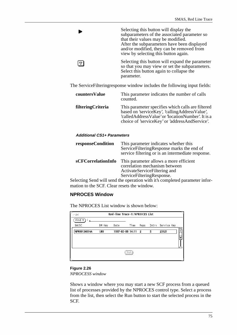
SMAS, Red Line Trace
75
Selecting this button will display the subparameters of the associated parameter so that their values may be modified.After the subparameters have been displayed and/or modified, they can be removed from view by selecting this button again.
Selecting this button will expand the parameter so that you may view or set the subparameters. Select this button again to collapse the parameter.
The ServiceFilteringresponse window includes the following input fields:
countersValue This parameter indicates the number of calls counted.
filteringCriteria This parameter specifies which calls are filtered based on ’serviceKey’, ’callingAddressValue’, ’calledAddressValue’ or ’locationNumber’. It is a choice of ’serviceKey’ or ’addressAndService’.
Additional CS1+ Parameters
responseCondition This parameter indicates whether this ServiceFilteringResponse marks the end of service filtering or is an intermediate response.
sCFCorrelationInfo This parameter allows a more efficient correlation mechanism between ActivateServiceFiltering and ServiceFilteringResponse.
Selecting Send will send the operation with it’s completed parameter infor-mation to the SCF. Clear resets the window.
NPROCES Window
The NPROCES List window is shown below:
Figure 2.26NPROCESS window
Shows a window where you may start a new SCF process from a queued list of processes provided by the NPROCES control type. Select a process from the list, then select the Run button to start the selected process in the SCF.

IN 2.3 Service Testing Course
76
When an entry from the NPROCES list is RUN, the system simulation date/time will be set to the time indicated by the list entry. Use Set Clock in the Edit menu to change the time back to the current date/time, if desired.

SMAS, Red Line Trace
77
2.30 Send MenuThe Send operations will open subwindows with input fields and various selections. To apply the input and close the subwindow select Send.
The Send menu includes the following options:
CallInformationReportThis operation sends specific call information to the SCF as requested by the SCF in a previous CallInformationRequest operation.
EventNotificationChargingThis operation sends a report to the SCF of the occurrence of a specific charging event type requested by the SCF in a previous RequestNotificationChargingEvent operation.
EventReportBCSM This operation notifies the SCF of a call related event previously requested by the SCF in a RequestReportBCSMEvent operation.
ApplyChargingReportThis operation reports charging related information to the SCF as requested by the SCF in a previous ApplyCharging operation.
SpecializedResourceReportThis operation is used as a response to a PlayAnnouncement operation.
PromptAndCollectUserInformation ResultThe PromptAndCollectUserInformation operation interacts with a call party in order to collect information. Sent as a response to PACUI operation.
ActivateServiceFiltering ResultThe ActivateServiceFiltering operation causes the SSF to handle calls to destinations in a specified manner without requests for instructions from the SCF. Sent as a response to ASF operation.
CS1+ Operations
ReleaseCallPartyConnection ResultThis operation displays a window where you may send the result of a ReleaseCallPartyConnection operation to the SCF.
Reconnect Result This operation displays a window where you may send the result of a Reconnect operation to the SCF.
HoldPartyConnection ResultThis operation displays a window where you may send the result of a HoldCallPartyConnection operation to the SCF.

IN 2.3 Service Testing Course
78
2.31 Error MenuThe Error operations will open subwindows with input fields and various selections. To apply the input and close the subwindow select Send.
The Error menu includes the following options:
ActivateServiceFilteringShows a window where you may return an errorcase of an ActivateServiceFiltering operation to the SCF.
ApplyCharging Shows a window where you may return an error case of an ApplyCharging operation to the SCF.
Callgap Shows a window where you may return an errorcase of a CallGap operation to the SCF.
CallInformationRequestShows a window where you may return an errorcase of a CallInformationRequest operation to the SCF.
Cancel Shows a window where you may return an errorcase of a Cancel operation to the SCF.
CollectInformation Shows a window where you may return an errorcase of a CollectInformation operation to the SCF.
Connect Shows a window where you may return an errorcase of a Connect operation to the SCF.
ConnectToResource Shows a window where you may return an errorcase of a ConnectToResource operation to the SCF.
Continue Shows a window where you may return an errorcase of a Continue operation to the SCF.
DisconnectForwardConnectionShows a window where you may return an errorcase of a DisconnectForwardConnection operation to the SCF.
EstablishTemporaryConnectionShows a window where you may return an errorcase of an EstablishTemporaryConnection operation to the SCF.
FurnishChargingInformationShows a window where you may return an errorcase of a FurnishChargingInformation operation to the SCF.
InitiateCallAttempt Shows a window where you may return an errorcase of an InitiateCallAttempt operation to the SCF.
PlayAnnouncement Shows a window where you may return an errorcase of a PlayAnnouncement operation to the SCF.

SMAS, Red Line Trace
79
PromptAndCollectUserInformationShows a window where you may return an errorcase of a PromptAndCollectUserInformation operation to the SCF.
ReleaseCall Shows a window where you may return an errorcase of a ReleaseCall operation to the SCF.
RequestNotificationChargingEventShows a window where you may return an errorcase of a RequestNotificationChargingEvent operation to the SCF.
RequestReportBCSMEventShows a window where you may return an errorcase of a RequestReportBCSMEvent operation to the SCF.
SendChargingInformationShows a window where you may return an errorcase of a SendChargingInformation operation to the SCF.
CS1+ Operations
ReleaseCallPartyConnectionShows a window where you may return an error case of a ReleaseCallPartyConnection operation to the SCF.
HoldPartyConnectionShows a window where you may return an error case of a HoldCallPartyConnection operation to the SCF.
Reconnect Shows a window where you may return an error case of a Reconnect operation to the SCF.
SignallingInformationShows a window where you may return an error case of a SignallingInformation operation to the SCF.
Handover Shows a window where you may return an error case of a Handover operation to the SCF.

IN 2.3 Service Testing Course
80
2.32 Assist MenuThe Assist operations will open subwindows with input fields and various selections. To apply the input and close the subwindow select Send.
The Assist menu includes the following options:
AssistRequestInstructionsShows a window where you may invoke an AssistRequestInstructions operation toward the SCF over an assisting dialogue.
SpecializedResourceReportShows a window where you may invoke a SpecializedResourceReport operation toward the SCF over an assisting dialogue.
ApplyChargingReportShows a window where you may invoke an ApplyChargingReport operation toward the SCF over an assisting dialogue.
PromptAndCollectUserInformation ResultShows a window where you may send the result of a PromptAndCollectUserInformation operation to the SCF over an assisting dialogue.
End Assisting DialogueEnds an assisting dialogue connection.
Cancel, Return Error Shows a window where you may return an errorcase of a Cancel operation to the SCF over an assisting dialogue.
PlayAnnouncement, Return ErrorShows a window where you may return an errorcase of a PlayAnnouncement operation to the SCF over an assisting dialogue.
Prompt&CollectUserInfo, Return ErrorShows a window where you may return an errorcase of a PromptAndCollectUserInformation operation to the SCF over an assisting dialogue.
ApplyCharging, Return ErrorShows a window where you may return an errorcase of an ApplyCharging operation to the SCF over an assisting dialogue.
DisconnectForwardConnection, Return ErrorShows a window where you may return an errorcase of a DisconnectForwardConnection operation to the SCF over an assisting dialogue.
FurnishChargingInformation, Return ErrorShows a window where you may return an errorcase of a FurnishChargingInformation operation to the SCF over an assisting dialogue.
SMAS, Red Line Trace
81
ReleaseCall, Return ErrorShows a window where you may return an errorcase of a ReleaseCall operation to the SCF over an assisting dialogue.
SendChargingInformation, Return ErrorShows a window where you may return an errorcase of a SendChargingInformation operation to the SCF over an assisting dialogue.

IN 2.3 Service Testing Course
82
2.33 Pane MenuThe RLT Pane Menu is a text menu, as shown here:
Figure 2.27Pane Menu window
The Pane menu window includes choices to zoom and print the SSL.
SMAS, Red Line Trace
83
2.34 Module Summary• SMAS is part of TMOS which is Ericsson’s concept for centralised
operation and maintence.
• If SMAS is not available, service handling can be done with the help of MML commands directly to the SCP.
• Service handling in SMAS covers a number of different areas: Service Creation, Service Deployment, Service Provisioning etc..
• Audit is used to compare data in a Network Element with the corre-sponding data in the SMAS database or between mated NEs.
• Red Line Trace is a debugging tool for services designed in SMAS.
• RLT allows the user to specify and uninstalled service or an SCP, pro-vide it with start values and simulate the interaction between the SSP, the SCP, and the SDP.

IN 2.3 Service Testing Course
84

Service Provisioning Subsystem (SES)
85
3. Service Provisioning Subsystem (SES)
3.1 Introduction Service Provision Subsystem (SES) implements the intelligent network functions in AXE and consists of central software only. Traditionally, all logic associated with subscriber services was held in the switching nodes to which subscribers were attached. Intelligent Networks make provision for services to be provided independent of a switching node.
IN in an architectural concept for creation and provisioning of new serv-ices. The implementation of this concept will faciliate the rapid introduc-tion of new services.
The telecommunication Standardisation Sector of the International Tele-communication Union (ITU-T) has published a set of recommendations regarding IN. The first set of recommendations is called Capability Set 1 (CS1). Based on these recommendations, the European Telecommunica-tion Standards Institute (ETSI) has published a standard for an IN Applica-tion Protocol (CS1 Core INAP).
Figure 3.1Module Objectives
3.2 SES StructureSES is divided into two functional elements:
• Service Control Function (SCF) which implements the SCP functional-ity
• Service Switching Function (SSF) which implements the SSP function-ality
SCF and SSF implemented in the same node provide the functionality of an SSCP
Module Objectives
After completing this module the participant will be able to:
• Be able to describe the main functions of the SES
• Be able to describe the main functions of the SSP and SCP
• Be familiar with the function blocks within SSP and SCP
• Understand how the IST table is built up
• Monitor the dialogue between the SSF and SCF
• Locate and correct fault in SSP and SCP.

IN 2.3 Service Testing Course
86
SES interworks with two elements:
• Service Management System (SMAS)
• Call and Connection Control
Figure 3.2SES Structure
The Service Control Function (SCF) is made up of the following:
• Service Programs - these programs enable the IN services to be imple-mented in a fast and efficient way.Services are defined using Control Types. These Control Types are combined into Service Scripts to describe an IN service.
• Service Processing - provides for the execution of service programs, that is, on a service request from the SSF, service processing invokes the functions of a Service Program.
• SSF-SCF Communication - establishes dialogue between SSF and SCF in an IN call. When SSF and SCF are within the same exchange (in a Service Switching and Control Point - SSCP), they have commu-
SMAS
Service Program
Service Processing
SSF - SCF Communication
SCF
SSF
Operation Processing
SSF - SCF Communication
Triggering TrafficProcessing
ResourceHandling
Call and Connection Control

Service Provisioning Subsystem (SES)
87
nication directly using AXE internal signals. When they are located in different exchanges, they use the signalling system CCS7 to communicate.Service Switching Function (SSF) is made up of the following:
• SCF-SSF Communication - will be explained in relation to SCF.
• Operation Processing - executes the operations requested from SCF (for example, a response to a service request from the Traffic Control Subsystem - TCS).
• Triggering - contains the triggering function, that is, a function to detect when an IN service is to be activated.
• Resource Handling- controls announcements when they are used in an IN call. This function also handles reception of the subscriber’s dialled digits.
Both SSF and SCF contain SCF communication functions. These func-tions are used to establish dialogue between SSF and SCF in an IN call. When in same AXE SSF-SCF communicate using AXE internal signals. When in separate they use C7 signalling.
IN services are introduced to SCF using SMAS via IOG11 input/output interface.
SES interworks with the following subsystems:
• Trunk and Signalling Subsystem (TSS)
• Group Switching Subsystem (GSS)
• CHarging Subsystem (CHS)
• Traffic Control Subsystem (TCS)
• Common Channel Signalling subsystem (CCS)
• Operation and Maintenance Subsystem (OMS)
• Statistics and Traffic measurement Subsystem (STS)
3.3 SES GroupsSES can be broken up into two different group products. With the products of each group, IN nodes can be configured. Products in a certain group will only function together with other products in the same group, not with products from the other group.
One group, consists of INAP, SSF, SCF, TC_USER, IWU-S12, IWU-EWSD, SSSIM and SSMM. This group is referred to as Group 1 below.
The second group, consists of INAPCS1, INAPCS1+, SSFSTD, SCFSTD, PHF, INTSIM and SSMM. This group is referred to as Group 2 below.
Both groups offer backwards compatibility. Group 2 offers compliance to ETSI CS1.

IN 2.3 Service Testing Course
88
3.3.1 Description of the Group 1 Products
Intelligent Network Application Protocol (INAP)The INAP specifies the operations in the interface between SSF and SCF as well as the parameters within the operations. INAP also specifies the procedures that must be followed on the interface, and the underlying models of the switching state in the SSF.
Service Switching Function (SSF)The SSF is the functional entity, embedded in a switching node of the net-work, which provides the network with access to the IN services in the SCF. It is responsible for forwarding a service request to the SCF when-ever a call has met the trigger conditions of an IN call.
It provides the interface to the SCF to allow services to interact with the calls and connections in the network. Its interface to the call and connec-tion control function gives the SSF access to the network resources and call instances in the network.
By means of a specified set of operations and events, the SSF offers a lim-ited view and influence of the network to the SCF. It is responsible for executing the requested operations from SCF and generating network related events of interest towards the SCF.
Service Control Function (SCF)The SCF controls the processing of IN services. It contains the service pro-grams, which constitutes the IN services, and provides for the execution of these.
On a service invocation request from the SSF, the SCF will select the requested service program and execute it. The SSF interface enables serv-ices to operate on connections and resources in the network. This limited interface to the network and the functional separation of network and serv-ice processing allows for network implementation independent service development and processing, i.e. the services are no longer dependent on the network implementation or network developments.
Services are introduced in the SCF via the Service Management interface. The same interface provides for the operation and maintenance of the serv-ice after its deployment.
S12 Interworking Function (IWU-S12)This interworking function is required in addition to (product) SCF when interworking towards S12 SSF is needed. The function provides transla-tion of Alcatel INAP into Ericsson INAP and vice versa. A TC-User part is also included in this function.
EWSD Interworking Function (IWU-EWSD)This interworking function is required in addition to (product) SCF when interworking towards EWSD SSF is needed. The function provides trans-lation of Siemens

Service Provisioning Subsystem (SES)
89
INAP into Ericsson INAP and vice versa. A TC-User part is also included in this function.
Transaction Capability User (TC-USER)The Transaction Capability User controls the usage of TCAP as a carrier for INAP. The TC-User builds TCAP messages from the INAP operation and is responsible for the establishment and maintenance of the dialogue between a SSP and SCP. This involves an activity test mechanism and the handling of reset indications.
Traffic Simulation (SSSIM)For testing purposes this function can simulate the SSF-SCF communica-tion towards either the SSF or the SCF. Furthermore it is possible to moni-tor the SSF-SCF communication.
Memory Management (SSMM)This function can control the size of all size alterable files in SES, from a central point in the subsystem.
It also takes care that the sizes of files in blocks SSI and SCFM are coordi-nated.
3.3.2 Description of the Group 2 Products
Intelligent Network Application Protocol CS-1 (INAPCS1)The functionality of this product is similar to that of the Intelligent Net-work Application Protocol in Group 1. The main difference is, that it is compliant to the ETSI Core INAP standard.
Intelligent Network Application Protocol CS-1+ (INAPCS1+)This product specifies the operations in the interface between SCF and SDF as well as the parameters within the operations. It also specifies the procedures that must be followed on the interface and the underlying mod-els. All this is according to an Ericsson protocol.
Service Switching Function CS-1 Standard (SSFSTD)The functionality of this product is similar to that of the Service Switching Function in Group 1. The main difference is, that it is compliant to the ETSI Core INAP standard.
Service Control Function CS-1 Standard (SCFSTD)The functionality of this product is similar to that of the Service Control Function in Group 1. The main difference is, that it is compliant to the ETSI Core INAP standard.
Protocol Handling FunctionThe functionality of this product is similar to that of the Transaction Capa-bilities User function in group 1.
Traffic Simulation (INTSIM)The functionality of this product is similar to that of the traffic simulation function in Group 1. This will be described in more detail later in this module.

IN 2.3 Service Testing Course
90
Memory Management (SSMM)The functionality of this product is similar to that of the traffic simulation function in Group 1. But there is no coordination of file sizes between blocks.
3.4 Service Switching Function (SSF)SSF (Service Switching Function) is part of the subsystem SES (SErvice provision Subsystem). It consists of central software only.
The SSF is a Functional Entity in the Intelligent Network Distributed Functional Plane Architecture. This product forms the Ericsson implemen-tation of SSF according to ETSI IN CS1 Core INAP with references to ITU CS1 recommendations.
The SSF provides the set of capabilities required for interaction between the Call Control Function (CCF) and the Service Control Function (SCF) in order to access and process services for subscribers in an Intelligent Network.
3.5 SSF-SCF CommunicationFor each IN call one or several dialogues may be established between SSF and SCF. Only one controlling dialogue is allowed.
The information flow between SSF and SCF consists of a set of remote operations. When the SSF and SCF are embedded in the same network ele-ment they communicate directly via AXE-10 signals. When the SSF and SCF are located in different network elements they use the Transaction Capabilities Application Part (TCAP) to communicate via the Signalling System Number 7 network. The set of operations is defined in an IN Application Protocol according to ETSI Core INAP CS1.
Figure 3.3Embedded Configuration
Service Control Function
ProtocolHandlingFunction
ServiceSwitchingFunction
SSCP
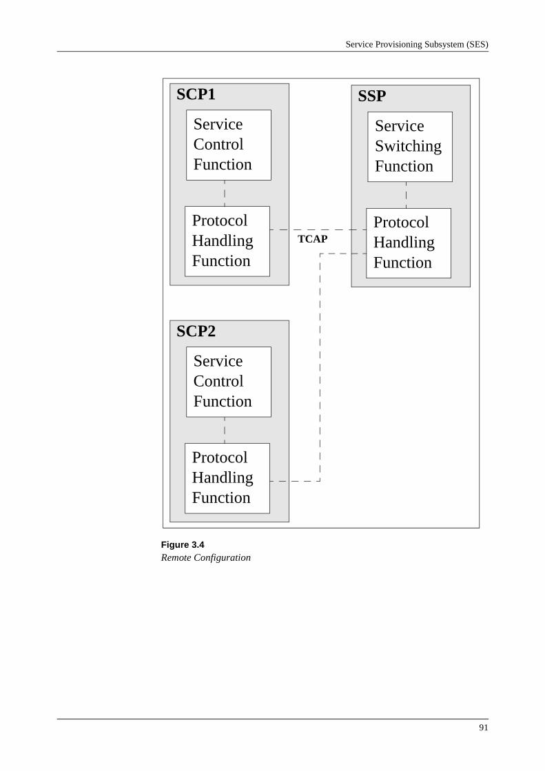
Service Provisioning Subsystem (SES)
91
Figure 3.4Remote Configuration
Service Control Function
ProtocolHandlingFunction
SCP1
Service SwitchingFunction
ProtocolHandlingFunction
SSP
Service Control Function
ProtocolHandlingFunction
SCP2
TCAP

IN 2.3 Service Testing Course
92
3.6 SSF Function Specification
3.6.1 Function Specification Description
Figure 3.5Functional structure of SSF and interface to other APT subsystems
For a description of the interfacing APT subsystems see Appendix “Description of SSF interfacing APT Subsystems”.
Dialogue ControlDialogue Control controls how dialogues are initiated, maintained, closed and coordinated by SSF. Several dialogues may exists for a single IN call segment, but only one at a time is allowed to influence the call processing i.e. single point of control. Other existing dialogues must be in a monitor relationship.
The dialogues are supervised by Finite State Machines (FSMs) and must behave according to determined rules for the FSMs. The FSMs reflects the state of the dialogues and controls the reception and sending of operations between SSF and SCF. Some FSMs realizes the possibility for SCF to
Service Control Function
Protocol Handling Function
Dialogue Control
Triggering Charging IN CallControl
Special ResourceHandling
MassCallServices
TCS CHS OMS ESS GSS STS
SSF

Service Provisioning Subsystem (SES)
93
have a view of the status for the call process and the connection process in SSF/CCF. Other FSMs are used by the SSF itself to have the total picture of the call status. Following FSMs are handled by this function:
• - Session FSM
This FSM coordinates several dialogues active on the same call and on the same SSF instance. The FSM is used by the SSF to decide if it is allowed to open a new dialogue (a control relationship) on a specific call segment.
• - Call FSM
The Call FSM handles the operation reception and sending on a per dia-logue level in a certain call segment in an initiating SSF. Several Call FSMs can be connected to the same Session FSM. The Call FSM reflects the view of the status for the call, for the SCF con-nected to the dialogue.
• - Non-call FSM
This FSM is used for controlling reception and sending of operations on a non call associated dialogue either opened by SSF or SCF.
• - Assist FSM
This FSM is used when SSF acts as an assisting SSF and controls the reception and sending of operations on a per dialogue level in a certain call segment. Only one Assist FSM can be connected to a Session FSM. The Assist FSM reflects the view of the status for the call, for the SCF connected to the dialogue.
TriggeringAt selection of IN an IN route and an IN Service Trigger (IST) is pointed out. The IST is available from the B-number analysis performed by the Traffic Control Subsystem (TCS). The initial conditions for the call han-dling must be prepared so that they may be applied for the rest of the IN call. An important part of this is the arming of the applicable Trigger Detection Points.
Trigger Detection Points are points in the basic call process where an IN service could be invoked, starting by sending the operation InitialDP.
Triggering occurs when a Trigger Detection Point (TDP) is armed and the criteria for this Detection Point is met during the call processing. Possible Call Gap or/and Service Filtering analysis is performed before allowing SSF to initiate a dialogue towards SCF. SSF will include data in the query to SCF according to settings in the trigger tables. The data is fetched by SSF from CCF.
The IN Service Trigger (IST) points out the necessary data (defined by commands) which are needed for further processing by the Service Logic in SCF as well as data needed by SSF for finding the correct SCP. Dependent on type, data can be defined on IST level or per Trigger Detec-tion Point within an IST.

IN 2.3 Service Testing Course
94
The Trigger function is also used when an assist dialogue is to be estab-lished towards SCF. This is triggered by defining specific IST values to reflect the ’assist case’.
Basic ChargingSSF, Basic Charging specifies the ways in which it is possible to influence the charging of calls handled by SSF.
Charging in the SSP of IN services is performed as a result of the ordinary charging analysis in the SSP and/or operations received from SCF. Charg-ing can be performed by Toll Ticketing and/or Pulse Metering. For some service types, such as Credit Card calls, only Toll Ticketing is applicable.
The following functionality is covered:
a) Guarantee that a TT-output is performed for the call.
b) Influence the charging of the call - Tariff Indicator to incoming leg - Input to charging analysis to outgoing leg - Charge indication in ISUP messages - Tariff change during the call - Pulse burst during the call
c) Start and stop charging
d) Additional of Billing Information. Including charge for the use of a specific service.
In connection to charging it is possible to decide per IN service trigger, or per call, whether meter pulses and charging messages should pass from outgoing to incoming leg.
It is possible to report the events: Received Charging Messages and spe-cific charging information to the Service Control Function.
Charging is covered in a later module.

Service Provisioning Subsystem (SES)
95
IN Call ControlThe IN Call Control is responsible for the interface to the call processing functions of the exchange. This interface allows SCF to control the call processing and the connectivity of the information channels for each leg in a call.
Figure 3.6Connections between IN Call Control and TCS
To control and monitor the call status, the IN Call Control Function has Call Leg State Machines (CLSMs). CLSM is the Ericsson projection of the Basic call State Model(BCSM). The CLSMs is based on a call-leg concept, where each access represented by a leg is explicitly reflected in a Finite State Model. The CLSMs deter-mines the Point in Call and when a Detection Point is reached. Possibili-ties exists for arming detection points at certain points in the CLSM. The detection points can be armed staticly by the Trigger function and are then called Trigger Detection Points (TDPs) or dynamically by SCF during a dialogue and are then called Event Detection Points (EDPs). This way it is possible for the SCF to have a view of the basic call processing activities.
Trigger Detection Point handling is described in the Module ’Triggering’. EDPs are used by SCF to monitor on certain call events during service execution.
Call events are reported up to SCF when armed EDPs are encountered. Detection points can be armed by the SCF as Event Detection Points in two different modes - ’Notify and Continue’ or ’Request’ mode. When a TDP or EDP armed in request mode is reported to SCF the basic call processing is suspended by SSF until an order is received from SCF to resume the call processing.
Call ProcessingFunction(TCS1)
IN Call ControlFunction(SSF)
Call ProcessingFunction(TCS2)
SCF

IN 2.3 Service Testing Course
96
When an EDP armed in notify-and-continue mode is reported to the SCF, the basic call process is NOT suspended by the SSF. The call processing continues immediately after the report is send to the SCF.
Any kind of interaction from SCF on the call control and call set-up proc-ess are handled by the IN Call Control.
Any other function in SSF can dynamically arm detection points in the CLSM, to be able to execute actions at a certain time in the call. When the detection point is reached, the functions will be informed about it and the specific action can be performed. Only one function is informed at a time to avoid interactions.
Figure 3.7Distribution of call events to different functions
To avoid interaction between actions caused by traffic events and actions caused by INAP events (operations received from the SCF or operations to be send to the SCF), the IN Call Control administrates a token. Any func-tion in the SSF must ask for the token before an operation is executed or before a traffic event are handled - except transmitting of traffic event that do not affect the SSF.
Specialized Resource FunctionSpecialized Resource Function describes how special resources can be controlled by IN when required for execution of IN provided services.
The special resources can be used and controlled by IN for:
- Simple announcements
- Announcement with variable parts
Call ProcessingFunction(TCS1)
IN Call ControlFunction(SSF)
Call ProcessingFunction(TCS2)
Mass CallServiceFunction
SSFChargingFunction
Special ResourceFunction

Service Provisioning Subsystem (SES)
97
- Monitoring for DTMF digits
- Voice prompting
- Generating of tones
- Generating of text
Note: It is only possible to send announcements/text or to monitor for DTMF digits to the initial leg (SSF initial or SCF initial leg).
A simple announcement can be played to the end-user one or a number of times. An announcement with variable parts gives the possibility to include up to five variable parts in an announcement.
Monitoring for DTMF digits can be done towards the end-user. When DTMF digits are received they can be reported up to SCF.
Voice prompting is used to play an announcement to the end-user and col-lect DTMF digits as response to the announcement and inform SCF about received information.
Tones (busy, congestion etc.) can be sent to the end-user and it is possible to give a duration for the tone sending.
It is possible for SCF to provide a text string to SSF for distribution to an end-user.
Counters in the measurement database for SSFThis specification describes the measurements provided in the Service Switching Function (SSF). The functionality is based on the system for Statistics and Traffic Measurements.
The following statistical functions are supported:
• Average number if records in use for size alterable files.
• Average congestion for size alterable files.
• Average number of failed accessed due to erroneous IN Trigger Data.
• Average number of failed outgoing calls due to erroneous route data.
• The quality of the dialogues by means of
- number of operations
- number of errors/rejects
- number of aborts
- number of timeouts (Tssf, Tsrf)
• Number of SCF invocations per
- Destination Point Code
- Global Title Logic
- Local destination

IN 2.3 Service Testing Course
98
- Global Title Service Number
- SCF id as Global Title
• Number of service requests for the Call Gap function
• Number of service requests for the Service Filtering function
Mass Call ServicesMass Call Services can be divided into two sub-functions namely Call Gap and Service Filtering.
• The Call Gap function is used to protect the SCF against overload. This is accomplished by reducing the rate of which specific service requests are sent to SCF. Call Gap is initiated from SCF via a specific operation or via a command interface. It is possible by SCF to decide the release procedure in SSF when a call is rejected i.e. send announcement, tone, text before releasing the call and/or include specific cause value at release.
• The Service Filtering function provides various mechanisms to filter calls according to specific algorithms. This can be used for televoting type of services, counting the rejected calls. A set of counters exists for this function and these can be reported up to SCF at occasions determined by SCF.
It is possible by SCF to decide the release procedure in SSF when a call is rejected i.e. send announcement, tone, text before releasing the call or include specific cause value at release.
Interaction between INAP and ISUPInteraction between INAP and ISUP e.g. how call processing INAP opera-tions affects ISUP signalling procedures and vice versa.
Ericsson support of Core INAP CS1, PICS SSPEricsson SSP is compliance towards ETSI Core INAP CS1 in forms of tables. These tables includes information such as ETSI Core INAP opera-tions, arguments, application contexts, interfaces etc.

Service Provisioning Subsystem (SES)
99
3.7 List of Function Specifications1. SSF, Dialogue Control
2. SSF, Triggering
3. SSF, Basic Charging
4. SSF, IN Call Control
5. Specialized Resource Function
6. Counters in the measurement database for SSF
7. SSF, Mass Call Services
8. SSF, Interaction between INAP and ISUP
9. Ericsson support of Core INAP CS1, PICS SSP
3.8 SSF Implementation
3.8.1 General DescriptionThe SSF is located in subsystem SES and inter-works with subsystems within APZ and with following APT subsystems:
- TCS Traffic Control Subsystem
- CHS Charging Subsystem
- OMS Operation and Maintenance Subsystem
- ESS Extended Switching Subsystem
- GSS Group Switching Subsystem
- STS Statistics and Traffic Measurement Subsystem
SSF also has an interface towards the Protocol Handling Function (PHF) within subsystem SES. PHF has an interface towards CCS when the SSF is able to communicate with an externally located SCF (SCP) and an inter-face towards SCF, when the SCF is located in the same node as the SSF i.e. SSCP configuration.

IN 2.3 Service Testing Course
100
3.8.2 SSF FunctionsThe figure below shows a rough grouping of the SSF functionality and the internal interfaces.
DialogueControl
MassCallServices
SpecializedResourceFunction
Triggering & IN Call Control
Charging
IN Clearing and FaultHandling

Service Provisioning Subsystem (SES)
101
3.8.3 Mapping SSF function to function blocksThe different functions owned by SSF are implemented in a number of function blocks. Below is shown a functional grouping of the SSF blocks.
Triggering
SSFTDA1, SSFTDA2, SSFDCF
IN Call Control
SSFDCF, SSFCCF, SSFEC, SSFCROH, SSFXCM
Mass Call Services
SSFCG, SSFCGA, SSFSF, SSFSFA, SSFMCS
Charging
SSFCHM
Dialogue Control
SSFDM, SSFEC
Specialized Resource Function
SSFSRF
IN Clearing and Fault Handling
SSFICFH
Figure 3.8Functional grouping of the SSF blocks
DialogueControl
Mass CallingService
SpecializedResourceFunction
Triggering &IN Call Control
Charging
SSFDMSSFEC
SSFCGSSFCGASSFSFSSFSFASSFMCS
SSFCHM
SSFTDA1SSFTDA2 SSFDCF
SSFCCFSSFFEC
SSFCROHSSFXCM
SSFSRF
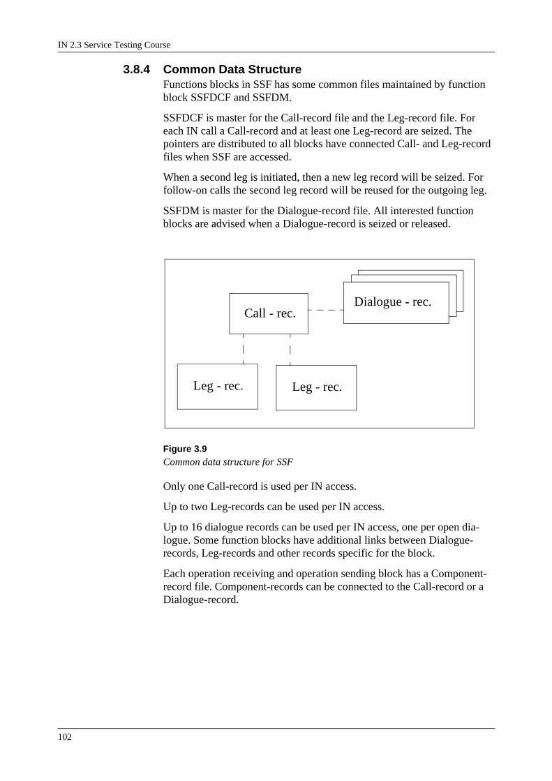
IN 2.3 Service Testing Course
102
3.8.4 Common Data StructureFunctions blocks in SSF has some common files maintained by function block SSFDCF and SSFDM.
SSFDCF is master for the Call-record file and the Leg-record file. For each IN call a Call-record and at least one Leg-record are seized. The pointers are distributed to all blocks have connected Call- and Leg-record files when SSF are accessed.
When a second leg is initiated, then a new leg record will be seized. For follow-on calls the second leg record will be reused for the outgoing leg.
SSFDM is master for the Dialogue-record file. All interested function blocks are advised when a Dialogue-record is seized or released.
Figure 3.9Common data structure for SSF
Only one Call-record is used per IN access.
Up to two Leg-records can be used per IN access.
Up to 16 dialogue records can be used per IN access, one per open dia-logue. Some function blocks have additional links between Dialogue-records, Leg-records and other records specific for the block.
Each operation receiving and operation sending block has a Component-record file. Component-records can be connected to the Call-record or a Dialogue-record.
Call - rec.
Leg - rec. Leg - rec.
Dialogue - rec.

Service Provisioning Subsystem (SES)
103
3.9 SSF Function Blocks
3.9.1 SSFDCFSSFDCF is the main data manager of the IN Call Control function.
SSFDCF is the master of the size alteration events for call records and leg records and it informs the blocks holding call records when a record must be initialized and when it is dismissed.
SSFDCF contains a file for route data defined by command EXRBC. This data will be used as default route data when route-index is defined in oper-ations Connect and/or InitiateCallAttempt.
SSFDCF contains a file for IN service trigger (IST) data defined by com-mands SWIPI, SWITI and SWRDI. IST data is used to arm trigger detec-tion points (TDP) and indicates which operation InitialDP or AssistRequestInstruction is to be send when the TDP is encountered in the call. Furthermore holds each TDP information about which contents the InitialDP should have if a call encounters the TDP and to which SCF the operation should be send to.
SSFDCF contains a file for destination route data defined by command SWSDI. These destination is used to route the InitialDP or AssistRequest-Instruction operations to the right SCF according to the destination indi-cated on a given trigger detection point on the IST.
When SSF is seized from TCS, SSFDCF is linked to RE where it reads the necessary data. After the reading SSFDCF is replaced in the traffic chain by SSFCCF.
SSFDCF stores the data received in operations from the Service Control Function and ’IAM’ data read from TCS (or through TCS).
When a trigger detection point is encountered, the SSFDCF will send either InitialDP or AssistRequestInstruction to the SCF with requested information according to the trigger data.
SSFDCF supplies data for operation sending as well as ’IAM’ data for rout-ing.
3.9.2 SSFCCFSSFCCF have two interfaces towards TCS, an IT- and an OT-interface. When SSFDCF has send either InitialDP or AssistRequest
operation to SCF (or it realized that no originating TDP exists) SSFCCF is linked into the traffic chain instead of SSFDCF.
SSFCCF receives, queues and handles signalling events.
SSFCCF contains a filter towards signalling events.
SSFCCF reports events such as detection points to SSFEC. The call processing is halted for the actual call during the event handling in the SSFEC. Until SSFEC or SSFCROH continues the call processing, all
IN 2.3 Service Testing Course
104
received signals - except disconnection signals - to and from the actual leg are buffered.
On order from SSFCROH, SSFCCF creates new outgoing legs. SSFEC takes care of the initialization of the leg records and informs the blocks holding the leg records, when a leg record must be initialized.
SSFEC administrates the token for the SSF. To prevent interactions when handling a received operation or an encountered detection point, a token is introduced. The token can be requested by any function at any time during the call. If the token is in use, the request will be added to a queue.
SSFEC maintains a CLSM on each leg. Every time an event is reported from SSFCCF/SSFDCF, SSFEC will update the CLSM on the leg on which the events has happened and if necessary also on the opposite leg.
Events are reported to SSFEC by all other blocks in the SSF that normally handles the events. The events can be that a detection point is meet or that a local event has happened. SSFEC handles the arming, disarming and reporting of different kind of events. When an armed event has occurred, SSFEC will inform all blocks that has asked for (armed) the event. If the event is a detection point, then SSFEC will occupy token before reporting the event. If the event is a local event the user must itself ask for the token if necessary.
When a the handling of a detection point is finished, SSFEC will check the remaining armings to update the Call FSMs, the Session FSM and check if the dialogues should still be kept open.
SSFEC handles the operations RequestReportBCSMEvent and CallInfor-mationRequest.
EventReportBCSM: SSFEC is requested for certain information when certain call events happens. The information is send to the SCF in opera-tion EventReportBCSM.
CallInformationRequest: SSFEC is requested for certain information when the call or a call leg disconnects. The information is send to the SCF in operation CallInformationReport.
3.9.3 SSFCROHSSFCROH handles the operations from SCF that affects the call process. The operations are CollectInformation, Connect, ConnectToResource, Continue, EstablishTemporaryConnection, DisconnectForwardConnec-tion InitiateCallAttempt and ReleaseCall.
CollectInformation operation: SSFCROH checks in SSFEC that DP2 (CollectedInfo) has been armed and that a number of required digits are specified. SSFCROH orders SSFEC to change the CLSM state to PointIn-Call CollectInformation.
Connect operation: SSFCROH orders SSFCCF to set up an outgoing leg to a new destination and connect it to an already existing initial leg (incom-ing or outgoing).
Service Provisioning Subsystem (SES)
105
ConnectToResource operation: SSFCROH informs SSFSRF to prepare for announcement sending, text sending or digit reception.
Continue operation: SSFCROH informs SSFCCF to continue the call processing after an InitialDP or an EventReportBCSM has been send to the SCF. If no outgoing leg exist, SSFCCF will continue by making an outgoing leg (implicit Connect). If outgoing leg exist SSFCCF will propa-gate the reported event and release buffered events.
SSFCROH will also inform SSFEC that the call processing continues. SSFEC will act as if handling of an event is finished.
• DisconnectForwardConnection operation: SSFCROH disconnects the connection towards the Assisting SSF.
• EstablishTemporaryConnection operation: SSFCROH uses an IT-inter-face towards TCS to set up a connection to an Assisting SSF.
• InitiateCallAttempt operation: SSFCROH orders SSFCCF to create an outgoing leg with no connection to another leg. This is only possible as the first leg in a call.
• ReleaseCall operation: SSFCROH orders SSFCCF to disconnect both incoming and outgoing leg. If a temporary connection exists, it will be disconnected as well.
3.9.4 SSFCHMSSFCHM provides SSF with an interface towards CHS, so that SSF is able to hold and resume charging, provide charge limit check and to store charging information in the TT records and determine charging.
SSFCHM handles the operations SendChargingInformation, Furnish-ChargingInformation, ApplyCharging and RequestNotificationChargin-gEvent.
• SendChargingInformation: SSFCHM will order to send charging infor-mation in the traffic link (tariff, charge indicator etc.).
• FurnishChargingInformation: SSFCHM will send charging information directly to the charging instance for the call/service (tariff, additional billing information etc.).
• ApplyCharging: SSFCHM is ordered to request charging related infor-mation from CHS at a certain event. The information is send to the SCF in operation ApplyChargingReport.
• RequestNotificationChargingEvent: SSFCHM is ordered to monitor for certain charging messages in the traffic link. The content of the charg-ing messages are returned to the SCF in the operation EventNotifica-tionCharging.
3.9.5 SSFICFHSSFICFH is a help function for clearing of calls in error situations. A Clearing program is invoked that defines the actions to be taken e.g. dis-playing information, clearing the call, continuing the call etc.

IN 2.3 Service Testing Course
106
The actions or sequence of actions can for each fault/clearing case be spec-ified by exchange data settings in the SSF.
Depending on the clearing program parameters and the state of the call, SSFICFH decides whether the call is to be released or, if possible, contin-ued.
3.9.6 SSFTDA1SSFTDA1 handles a part of the command reception and printout of trigger table and traffic related data as well as service data, e.g. for setting of IN trigger analysis data. The rest is handled by SSFTDA2.
Commands
SWIPE
Service Switching IST Procedure End
Terminates the specification of an IN service trigger.
SWIPI
Service Switching IST Procedure Initiate
Initiates the specification procedure of an IN service trigger (IST).
SWIDI
Service Switching IST Data Initiate
Defines the IN service trigger default settings.
SWISE
Service Switching IST Settings End
Removes IN service trigger data settings from the not operating area.
SWISP
Service Switching IST Settings Print
Print all data for one or all IN service triggers (IST).
SWITI
Service Switching Invoke Table Initiate
The command defines a Invoke Table. The purpose of the Invoke Table is to define which parameters should be send to the SCF when a dialogue is opened.
SWRDIService Switching Routing Data Initiate
Defines the Routing Table and connects the Routing Table to a specific Trigger Detection Point. The purpose of the data in the Routing Table is to secure that the correct SCF and Service Logic Program is invoked.

Service Provisioning Subsystem (SES)
107
SWTDEService Switching Trigger Detection End
Removes a specified Trigger Detection Point and all connected data like Invoke Table and Routing Data.
Printout
- SSF IN SERVICE TRIGGER DATA
3.9.7 SSFTDA2The block SSFTDA2 implements a part of the command initiated func-tions to administer IN service trigger data. The block handles command reception and printout for IN Destination data and Exchange data. The rest is handled by SSFTDA1 Further it handles commands used to copy, clear or switch the operating area (OP) and the not operating area (NOP) in block SSFDCF.
Commands
SWTZIService Switching Trigger Zeroing, Initiate
Initiates zeroing of the entire not operating area for IN service trigger anal-ysis.
SWTCIService Switching Trigger Copy, Initiate
Initiates copying of the operating area for IN service trigger analysis to the not operating area.
SWTAIService Switching Trigger Activate, Initiate
The command activates IN service trigger data which previously has been setup by several initiating commands.
SWTARService Switching Trigger Activate, Reset
Initiates a switch to previously used IN service trigger data, if the protec-tion period has not elapsed.
SWPTIService Switching IN Service Trigger Procedure, Initiate
Clears the protection time on the not operating area.
SWSDIService Switching Service Control Function Destination, Initiate
Defines destination data to be used when routing against SCP.
SWSDEService Switching Service Control Function Destination, End

IN 2.3 Service Testing Course
108
Removes a SCP destination of the type DPC or GT logical. SWSDP Prints data for one or all of the defined SCP destinations
SWSECService Switching Exchange Data, Change
The command is used to set IP SSP Capabilities and location of cause originator (LOC) parameters or default values for operation types Initiate Call Attempt, Establish Temporary Connection and Connect.
SWSEPService Switching Exchange Data, Print
Initiates a printout of exchange data.
Printouts
- SCF DESTINATION DATA
- SSF EXCHANGE DATA
- IST USED IN B-NUMBER ANALYSIS, LINE BASED SERVICES OR CALL IN PROGRESS.
3.9.8 SSFSFASSFSFA handles the commands and printouts in conjunction with service filtering.
Commands
SWFPIService Switching, Service Filtering Procedure, Initiate
Initiates the specification procedure for Service Filtering data.
SWFPEService Switching, Service Filtering Procedure, End
Terminates the Service Filtering specification procedure
SWFSIService Switching, Service Filtering Specification, Initiate
Specifies Service Filtering data for a given Service Filtering Criteria.
SWFSEService Switching, Service Filtering Specification, End
Removes data for a specific Service Filtering Criteria.
SWFSPService Switching, Service Filtering Specification, Print
Initiates printout of Service Filtering Criteria, data and counters.
Printouts
- SERVICE SWITCHING SERVICE FILTERING RESULT

Service Provisioning Subsystem (SES)
109
3.9.9 SSFCGASSFCGA handles the commands and printouts in conjunction with call gap.
Commands
SWGPEService Switching Call Gap Procedure, End
Terminates the specification procedure for Call Gap data.
SWGPIService Switching Call Gap Procedure, Initiate
Initiates the specification procedure in order to specify Call Gap data.
SWGSEService Switching Call Gap Specification, End
Removes data for a specific Call Gap criteria.
SWGSIService Switching Call Gap Specification, Initiate
Specifies Call Gap data for a specific type of Call Gap criteria.
SWGSPService Switching Call Gap Specification, Print
Initiates printout of Call Gap Criteria and data.
Printouts
- SERVICE SWITCHING CALL GAP DATA
3.9.10 SSFCGSSFCG protects the SCF against overload by rejecting calls in the SSF according to Call Gap mechanism.
SSFCG handles the operation CallGap.
3.9.11 SSFSFSSFSF provides a mechanism to reject calls either on basis of an interval specification or on basis of number of calls.
SSFSF handles the operation ActivateServiceFiltering
3.9.12 SSFSRFThe block handles and controls the interface towards announcement equipment and gives directives towards the IN Call Control. SSFSRF han-dles the operations PlayAnnouncement and PromptAndCollect.
For both operations it is possible to play an announcement, send a tone or a text. When e.g. an announcement is to be played or a tone is to be send on a leg, SSFSRF will select the announcement device and control it. Then
IN 2.3 Service Testing Course
110
it will request the IN Call Control to set the proper state in the Leg Level FSM and establish the connection in GS.
When a text is to be send, SSFSRF will order SSFCCF to send the text in a xxx message in the traffic link.
3.9.13 SSFDMThis block is responsible for handling (opening, closing and supervision) of dialogues. SSFDM is the connection between the Protocol Handler and the operations handlers in the SSF. SSFDM administrates all operation reception and operation sending to and from the SSF. SSFDM maintains a table for distribution of operations and distribute the operations to the right operation handlers. SSFDM collects operations from the SSF to the SCF so that they are send in the most efficient way (as many operation in one message as possible).
SSFDM handles the operation Cancel. When InvokeID is specified, SSFDM will order SSFSRF to cancel a specific operation. When ’ALL’ is specified SSFDM will order SSFEC and SSFCHM to cancel all outstand-ing reports to the SCF. The dialogue will not be closed even though no reports are outstanding. The SSF will wait for new orders from the SCF.
3.9.14 SSFXCMSSFXCM has the interface from SSF to the group switch. SSFXCM con-nects and releases passes in the group switch in the
appropriate way for the situation. SSFXCM is ordered to connect or release passes from SSFCCF.
To change the passes in the group switch, SSFCHM also have the connec-tion to the call control functions (CLCOF). SSFXCM makes sure that both CLCOFs are updated with the correct MUPs and connections.
SSFXCM is not operation receiving.
3.9.15 SSFMCSSSFMCS handles the traffic part of the Call Gap and the Service Filtering functions and the connection to the special resource functions (SRF).

Service Provisioning Subsystem (SES)
111
3.9.16 Link Pictures
Figure 3.10Call accessing SSF - before full number is received.
Figure 3.11Call accessing SSF - full number is received. An InitialDP is send to the SCF.
inc.trunk CHS TCS SSFDCF
SSFXCM
SSFCHM SSFCCF
SSFEC
inc.trunk CHS TCS
SSFXCM
SSFCHM
SSFCCF
SSFEC
SSFDCF

IN 2.3 Service Testing Course
112
Figure 3.12Call accessing SSF - full number is received. An announcement is connected to the incoming leg.
inc.trunk CHS TCS
SSFXCM
SSFCHM
SSFCCF
SSFEC
SSFDCF
ESSSSFSRF
SSFCROH
SSFDM

Service Provisioning Subsystem (SES)
113
3.10 Service Control Function (SCF)The figure below shows how SCF fits into the functional architecture of Intelligent Networks (IN), and the functional structure inside SCF.
Figure 3.13Functional Architecture of IN
The Service Control function controls the processing of IN services. It contains the service programs, which constitutes the IN services, and pro-vides for the execution of these.
3.10.1 SSF-SCF CommunicationFor each IN call a dialogue will be established between SSF and SCF. In this dialogue the SSF and SCF can communicate via a specified set of operations.
When the SSF and SCF are embedded in the same network element they communicate directly via AXE-10 signals.
When the SSF and SCF are located in different network elements they use the Transaction Capabilities Application Part (TCAP) to communicate via the Signalling System Number 7 network. The set of operations is defined in an IN Application Protocol (INAP).
Service Creation & Management
Service Switching Function
Service Processing
SCF - SSF Communication
Service Program

IN 2.3 Service Testing Course
114
3.10.2 Service ProgramsA Service Program contains logical constructs which provides the instruc-tions for realization of the service in the network.
Service programs are constructed from instances of SIB’s (Service Inde-pendent building Block, in Ericsson terminology called Controltypes), which upon their execution invoke functional routines in the SCF. These functional routines may invoke actions in the SSF to access or control net-work resources or invoke functional actions on data or resources in the SCF.
The logical construct is build by interconnecting instances of SIB’s to each other, and upon execution, constitutes the flow of service processing.
3.10.3 Service ProcessingThe Service Processing function provides for the execution of the service programs. On a service request from the SSF, it will interpret the relevant service program by invoking the functional routines required from the service program.
Service processing contains and manages the service programs and service data (i.e. all persistent data in the SCF). On invocation of a service pro-gram, it creates a service process to maintain all process data for the serv-ice program.
3.11 SCF Function Specification
3.11.1 Service Script Interpreter, GeneralThe service script interpreter stores and maintains all service scripts (and related data) in the service database and interprets these service scripts on request. The service database is capable of changing, introducing and test-ing new service programs without any traffic disturbance on existing or old services.
The interpreter provides the service with a synchronous environment for service execution. Whenever the interpreter is invoked it creates a service process (i.e. processing context) to execute service scripts, store process data (i.e. data received in the invocation and subsequent operation results/events) and buffer incoming events until they can be processed.
The interpreter executes the logical flow of SIB instances in the service program and invokes the controltype logic for each encountered SIB instance. The capabilities of each controltype are described in separate functional specifications.
A SIB instance can request monitoring of events in the SSF (call events or operation related events). When an event is received the interpreter will associate it with a service process and execute the SIB instances which monitored the event.

Service Provisioning Subsystem (SES)
115
3.11.2 Ericsson’s Protocol for IN, Version 2Here the relationships between controltypes, as independent building blocks of a service, and the external protocol are described. These external relationships are supported by operations and parameters, which defines the functional behaviour of the service.
The external relationship and also the internal relationship of controltypes with the internal data items are described. Data items can support the con-troltype directly, by providing necessary data
(Service Support Data) needed to perform its function, and indirectly by supplementary data (Call Instance Data) provided by the Basic Call Proc-ess (BCP).
3.11.3 Service Script Interpreter, Basic ControltypesBasic controltypes are the controltypes which provide the interpreter with the basic capabilities, i.e. elementary functions required for service pro-gram design.The controltypes can be divided in the following categories:
• Interwork functionsThese control the execution flow of Service Scripts (SS)
• Information functionsUsed to load data to the communication channel towards the SSF
• Selection functionsBranching functions on various types of data
• Network protection and distribution functionsFor keeping track of and influencing network utilization.
• Table branching functionsFunctions to branch on indexed tables
• Number manipulation functionsFunctions to edit and compare variables of type Number
• Response functionsInitiates sending of loaded data on the communication channel and ter-minates Service Script execution.

IN 2.3 Service Testing Course
116
3.11.4 Service Script Interpreter, Basic Controltypes 2Basic controltypes set 2 have similar functions as the ones previous, some of them are extensions/enhancements of the controltypes. The simpler ver-sions are maintained however to provide compatibility for Service Pro-grams with former products.
The controltypes can be divided in the following categories:
• Interwork functionsThese control the execution flow of Service Scripts (SS)
• Selection functionsBranching functions on various types of data
• Network protection and distribution functionsFor keeping track of and influencing network utilization
• Number and variable manipulation functionsFunctions to manipulate variables and numbers
• System functionsOperations directed to the interpreter to control SS execution
• Timer functionA relative timer mechanism.
3.11.5 Service Script Interpreter, Basic Controltypes 3The basic controltypes set 3 are the controltypes related to the connection model. Generally these cover the operations for manipulating connections in the SSF and monitoring of events in the SSF.
3.11.6 Service Script Interpreter, Number AnalysisThe number analysis controltype is used for obtaining an SS identity on basis of an input number. The controltype in the next section is an exten-sion of this controltype. The Number Analysis controltype is maintained to provide compatibility for service programs with former products.
3.11.7 Service Script Interpreter, Extended Number AnalysisThis controltype is used for analysis of numbers, the obtained results can be used in the SS for further processing.As result of the number analysis, the controltype may activate the conges-tion control function in the SSF.
3.11.8 Service Script Interpreter, QueuingThe controltype queuing enables services to put calls in a queue when they can not be handled immediately. Subscribers in the queue can either be connected to an announcement machine or be called back when they can be handled.The controltype has different modes of operation to enable full queue con-trol for the Service, e.g. call pick up from the queue, insert/remove from queue, access to queue parameters.

Service Provisioning Subsystem (SES)
117
3.11.9 Service Script Interpreter, Customer ControlThe Customer Control (CC) controltype allows customers to change data in their service scripts. The scope of a change (i.e. which data in what con-troltypes may be changed) and the procedure to fetch the new data (i.e. by subscriber procedures, as call data or constants) are defined by a CC pro-cedure. These procedures are defined by the operator and globally availa-ble to all Service Scripts. Per service script a CC case identifies the SIB instance which is to be changed and the procedure to change it.
3.11.10 Service Script Interpreter, Voice PromptingThe voice prompting controltype enables the service to interact with sub-scribers, i.e. playing of announcements and reception of a response in the form of digits. Voice prompting can initiate announcement sending to any party involved in the service process in SSF, where each announcement can include one or more variable parts (i.e. telephone number, time, price information, etc.). Simultaneous or after announcement, digit reception can be started to receive a subscriber response. Digit reception can be controlled by time supervision, number length or a number mask (i.e. prefix or suffix code or a predefined number).The digit reception procedure can include a limited number of retries and allows use of correction digits.
3.11.11 Service Script Interpreter, External SDF InterfaceThe external SDF interface consists of two controltypes. One controltype for reading from and one for writing to an external database. The function is able to receive spontaneous updates from an external database. On reception of an update, a service process will be created and a service script is started which takes care of the received update information.
3.11.12 Service Script Interpreter, Statistics CountersThe statistics counter function consists of 5 controltypes and some sub-functions to issue and handle statistics record output. The controltypes can maintain the following counters:
• counters for execution statistics of a certain SIB instance. This SIB instance can be of any controltype, or a specific statistics controltype may be used for this.
• :counters for various call events, e.g. B-answer, B-busy, No-reply, con-gestion, A-termination, error.
• general purpose counters (i.e. not tied to specific events) with or with-out threshold values.
Statistics record output can be initiated on time interval basis or on basis of the number of invocations of a SIB instance (of a specific statistics con-troltype). Furthermore the function will format and transfer statistic records for binary or alphanumeric output.
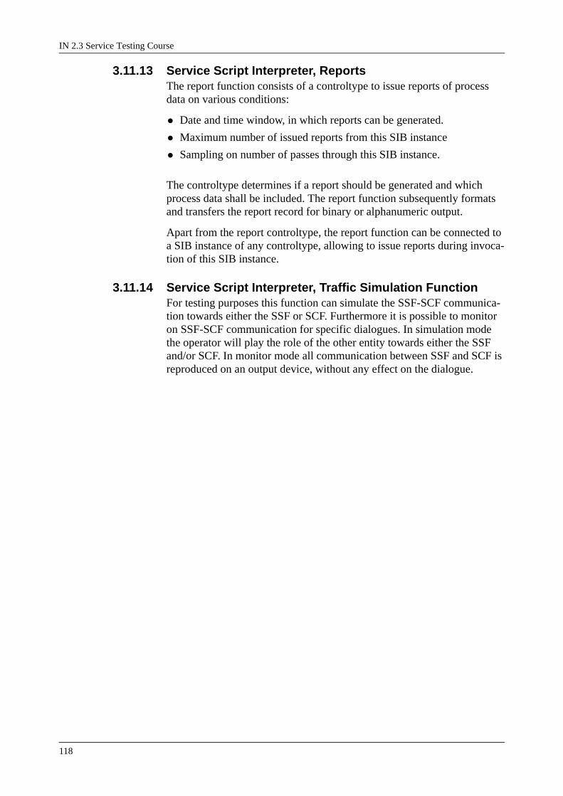
IN 2.3 Service Testing Course
118
3.11.13 Service Script Interpreter, ReportsThe report function consists of a controltype to issue reports of process data on various conditions:
• Date and time window, in which reports can be generated.
• Maximum number of issued reports from this SIB instance
• Sampling on number of passes through this SIB instance.
The controltype determines if a report should be generated and which process data shall be included. The report function subsequently formats and transfers the report record for binary or alphanumeric output.
Apart from the report controltype, the report function can be connected to a SIB instance of any controltype, allowing to issue reports during invoca-tion of this SIB instance.
3.11.14 Service Script Interpreter, Traffic Simulation FunctionFor testing purposes this function can simulate the SSF-SCF communica-tion towards either the SSF or SCF. Furthermore it is possible to monitor on SSF-SCF communication for specific dialogues. In simulation mode the operator will play the role of the other entity towards either the SSF and/or SCF. In monitor mode all communication between SSF and SCF is reproduced on an output device, without any effect on the dialogue.
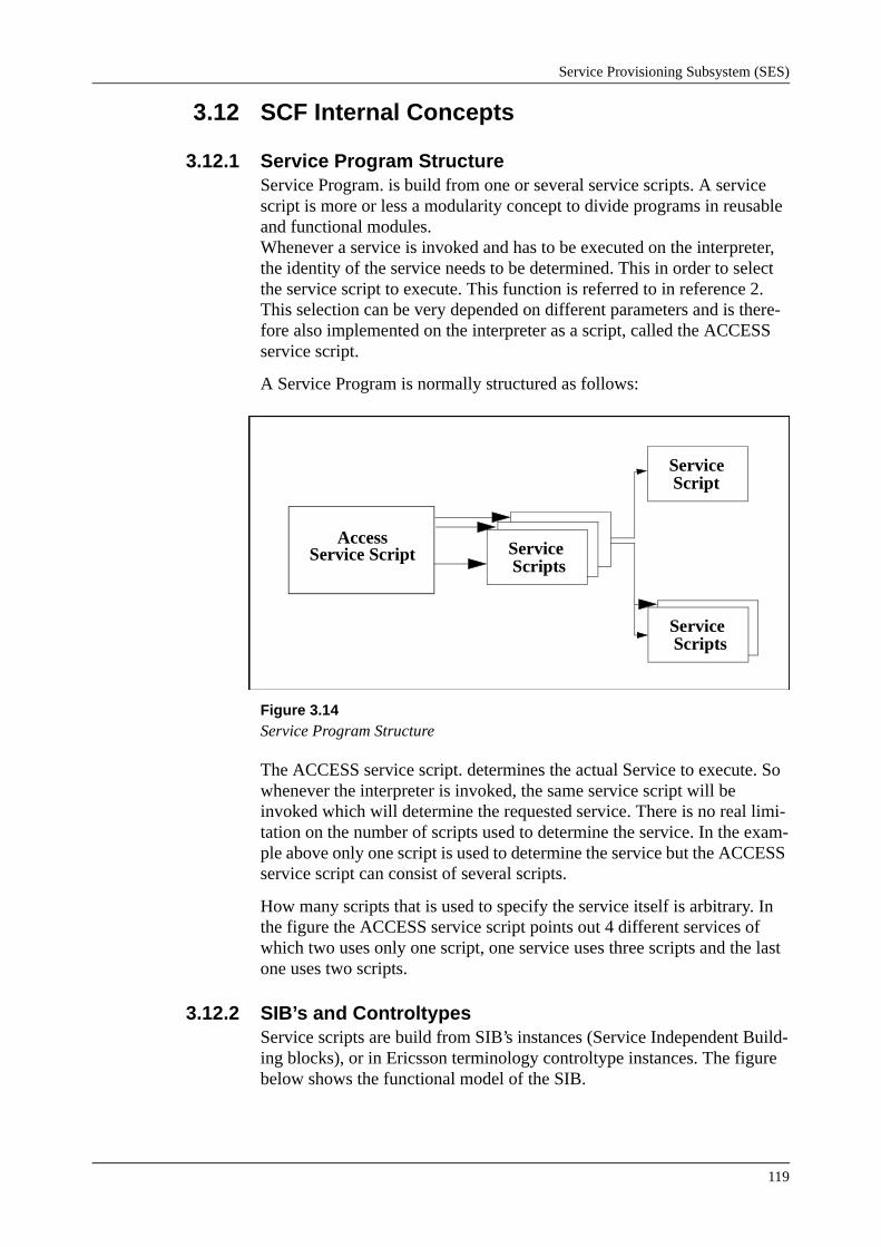
Service Provisioning Subsystem (SES)
119
3.12 SCF Internal Concepts
3.12.1 Service Program StructureService Program. is build from one or several service scripts. A service script is more or less a modularity concept to divide programs in reusable and functional modules. Whenever a service is invoked and has to be executed on the interpreter, the identity of the service needs to be determined. This in order to select the service script to execute. This function is referred to in reference 2. This selection can be very depended on different parameters and is there-fore also implemented on the interpreter as a script, called the ACCESS service script.
A Service Program is normally structured as follows:
Figure 3.14Service Program Structure
The ACCESS service script. determines the actual Service to execute. So whenever the interpreter is invoked, the same service script will be invoked which will determine the requested service. There is no real limi-tation on the number of scripts used to determine the service. In the exam-ple above only one script is used to determine the service but the ACCESS service script can consist of several scripts.
How many scripts that is used to specify the service itself is arbitrary. In the figure the ACCESS service script points out 4 different services of which two uses only one script, one service uses three scripts and the last one uses two scripts.
3.12.2 SIB’s and ControltypesService scripts are build from SIB’s instances (Service Independent Build-ing blocks), or in Ericsson terminology controltype instances. The figure below shows the functional model of the SIB.
Access Service Script Service
Scripts
ServiceScript
ServiceScripts
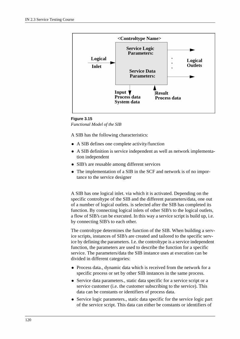
IN 2.3 Service Testing Course
120
Figure 3.15Functional Model of the SIB
A SIB has the following characteristics:
• A SIB defines one complete activity/function
• A SIB definition is service independent as well as network implementa-tion independent
• SIB’s are reusable among different services
• The implementation of a SIB in the SCF and network is of no impor-tance to the service designer
A SIB has one logical inlet. via which it is activated. Depending on the specific controltype of the SIB and the different parameters/data, one out of a number of logical outlets. is selected after the SIB has completed its function. By connecting logical inlets of other SIB’s to the logical outlets, a flow of SIB’s can be executed. In this way a service script is build up, i.e. by connecting SIB’s to each other.
The controltype determines the function of the SIB. When building a serv-ice scripts, instances of SIB’s are created and tailored to the specific serv-ice by defining the parameters. I.e. the controltype is a service independent function, the parameters are used to describe the function for a specific service. The parameters/data the SIB instance uses at execution can be divided in different categories:
• Process data., dynamic data which is received from the network for a specific process or set by other SIB instances in the same process.
• Service data parameters., static data specific for a service script or a service customer (i.e. the customer subscribing to the service). This data can be constants or identifiers of process data.
• Service logic parameters., static data specific for the service logic part of the service script. This data can either be constants or identifiers of
Parameters:Service Logic
Parameters:Service Data
LogicalOutlets
Logical ...Inlet
Input Result Process dataSystem data
Process data
<Controltype Name>
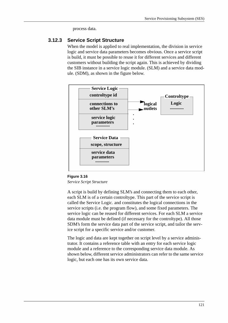
Service Provisioning Subsystem (SES)
121
process data.
3.12.3 Service Script StructureWhen the model is applied to real implementation, the division in service logic and service data parameters becomes obvious. Once a service script is build, it must be possible to reuse it for different services and different customers without building the script again. This is achieved by dividing the SIB instance in a service logic module. (SLM) and a service data mod-ule. (SDM), as shown in the figure below.
Figure 3.16Service Script Structure
A script is build by defining SLM’s and connecting them to each other, each SLM is of a certain controltype. This part of the service script is called the Service Logic. and constitutes the logical connections in the service scripts (i.e. the program flow), and some fixed parameters. The service logic can be reused for different services. For each SLM a service data module must be defined (if necessary for the controltype). All those SDM’s form the service data part of the service script, and tailor the serv-ice script for a specific service and/or customer.
The logic and data are kept together on script level by a service adminis-trator. It contains a reference table with an entry for each service logic module and a reference to the corresponding service data module. As shown below, different service administrators can refer to the same service logic, but each one has its own service data.
connections to
controltype id
logicaloutlets
.
.
.
Service Logic
other SLM’s
service logicparameters
............
Controltype
Logic............
service data
scope, structure
parameters
Service Data
............

IN 2.3 Service Testing Course
122
Figure 3.17Service Script
Note that the above picture shows actually three different service scripts (one per service administrator) which all use the same service logic.This structure allows for the reuse of complete service logic with different data. But the reuse of complete services for different customers requires another class of data, i.e. the part of the service that is tailored for the cus-tomer is normally very small compared to all service data of the service script. For instance call transfer will only need a C-number per customer while all other service data in the service logic program is typically the same for all customers.
Service data modules can be of different classes:
• data modules per service administrator
• global data modules, which can be used from any script by a SIB instance of the corresponding controltype.
• data modules per service customer.
The class of the data per SDM is also kept in the reference table of the service administrator and for the first two the reference to the actual serv-ice data module as well.
The reference to a Service Customer. can be determined anywhere in a service program, before the first service customer data module is encoun-tered (e.g. the access script). The Service Customer reference is estab-lished at run-time dynamically (for instance by analysing the A-number) and valid through the complete service process (not just per script).
service logic
service dataservice admin.
Service Script

Service Provisioning Subsystem (SES)
123
Figure 3.18Data Reference
Therefore a service customer has its own service data reference table inde-pendent of the service script (data of a certain Service Customer can be used in several scripts).
3.13 SCF InterfaceFor service programs, the SCF interface represents the communication channel to the outside world, i.e. beyond the interpreter. The interpreter and the services are invoked through this interface, and during service exe-cution it is the communication link to the SSF for the service.
Figure 3.19SCF Interface
The interpreter supports the following interface:
• Seizure, a service process is created in the interpreter and an access
Service
ServiceCustomer
ServiceLogic
Administrator
GlobalService Data
LocalService Data
ServiceCustomer Data
Ref.
InterpreterKernel
SCFInterface
Simulator

IN 2.3 Service Testing Course
124
service script is executed.
• Change process state, inform interface about changed processing state
• Event, incoming event for this service process.
• Send data, send the following data on the communication channel
• Release, release the communication link and service process.
3.13.1 Internal SCF-SSF ProtocolAt seizure of the interpreter a service process is created to execute the requested service upon. The process will provide the service with a syn-chronous execution environment which means that no external events or operations, directed to a service process, can interrupt script execution.Only when the service program itself suspends the execution, new external events are handled.
The SCF interface will adapt the asynchronous internal protocol, used between the SCF and SSF, to the synchronous interface of the interpreter. All incoming events will be buffered as long as the process state doesn’t allow new events to come in. The interpreter will report to the interface whenever it is ready to receive the next event for a process (by reporting changes of process state).
SIB’s acting on SSF objects, or services with explicit operations towards the communication channel, will send their operations to the SCF interface function. The interface will translate these sending requests to the internal SCF-SSF protocol and forward them to either the SSF or an adaptation function for an external protocol (e.g. a TC-user function).
The internal protocol supports the following operations:
• Seizure, bidirectional. Seizure of SCF from SSF or seizure of SSF from a SCF service.
• Operation request/indication. Sending or reception of an operation on the communication channel.NOTE: events are regarded as operations in this protocol.
• Release, bidirectional.
All operations and their parameters are segmented on AXE 10 signals, i.e. the operations can normally carry more data than one AXE 10 signal. The parameters and operation identifiers are coded according to the Tag/Length/Value principle.
3.13.2 SCF/SSF SimulatorThe SCF interface is provided with a test and monitor function. A simula-tor function is able to simulate either part (SSF or SCF) of the internal pro-tocol. By connecting the simulator as monitor on the communication channel, all operations can be sent to an output device and as well passed on to the receiver (SCF, SSF or the external protocol adapter).

Service Provisioning Subsystem (SES)
125
At seizure, i.e. setup of the communication channel between SSF and SCF, it is determined if a simulator is needed on basis of trigger data in the SSF or parameters received in the external protocol (in case of a remote initi-ated test). The simulator is seized on service process basis, i.e. simulation and moni-toring takes place per communication channel. The simulator can also be invoked by SCF depending on the specified function.
3.14 SCF Interpreter KernelThe interpreter kernel is the core of the SCF, including the interpreter, the service database (where all service logic and data is stored), database maintenance and the IO interface to the database.
3.14.1 Controltype SubscriptionInitially the interpreter has no controltypes for interpretation of service scripts. All controltypes present in SCF have to identify themselves to the interpreter at restart, i.e. they subscribe to the interpreter.
During subscription the controltype owning block sends all attributes and properties of the controltype to the kernel. Basically this information tells the interpreter how it should treat SIB instances of this controltype during service processing and how these SIB instances are defined on the I/O interface of the database.More specific:
• Identity of the controltype and location of the controltype logic + serv-ice data modules, i.e. external, mixed or in the kernel (interpreter and database).
• Type and format of service logic parameters for I/O and storage of serv-ice logic modules.
• Type and format of service data parameters for I/O and storage of serv-ice data modules.
• Control information for service processing. For instance job length, controltype logic in form of loadable code (e.g. internal controltypes).
Above the distinction has been made between internal and external (from the kernel’s viewpoint) controltypes on basis of the location of the con-troltype logic and the service data modules. However some controltypes are a mix of both, i.e. have service data stored both in the kernel and exter-nal.The SIB interpreter contains an LLA (Low Level Action) interpreter which is capable of executing loadable (to the kernel) LLA programs. These are a list of very simple procedure calls, which are dispatched by the LLA interpreter to the corresponding code sequences.By use of LLA, the controltypes can load their controltype logic into the interpreter during subscription phase.
IN 2.3 Service Testing Course
126
The internal controltypes have no external controltype logic, only LLA programs. The mixed and external controltypes also load LLA programs in the kernel at subscription, but mainly for activation of the external con-troltype logic when a SIB of that controltype is executed in the interpreter.
3.14.2 Service ProcessingEach service process has its own data area in the interpreter. Besides from storing control info for the interpreter (like process state, service adminis-trator/customer references, etc.), all dynamic variables are allocated in this area during service processing. This is data received from the communica-tion channel (e.g. at seizure or events) or variables created by SIB’s during script interpretation, all coded according to Tag/Length/Value format. The coding format accomplishes a service independent process record, i.e. no dependency between the interpreter and dynamic service data.
All monitor requests for events are registered as well on process basis, so the interpreter can find the issuer of the request (the SIB instance) as an event comes in.
The interpreter engine.For each SIB the interpreter has to execute, it returns to the same execution loop. In the description below it is assumed that the reference to the SIB instance, i.e. the logical inlet, is already established (from a previous SIB instance or as first SIB instance in a script). The interpreter reads the controltype of the SIB instance from the service logic module and looks up the LLA program of the controltype. The serv-ice data module is addressed (via the reference table in the service admin-istrator/customer) and the interpreter calls the controltype logic. If it is located externally, the required process data is sent along. The controltype logic takes over and will do whatever it is designed to do (i.e. it has access to all its service logic and data parameters, the process data and the com-munication channel). The results are returned to the interpreter which will look up the connection to the next SIB instance (if any logical outlet was returned) in the service logic module according to this result.
Incoming events are looked up in the registered monitor requests and directed to the SIB’s which had requested the event (if any). The con-troltype logic of the SIB can then decide if interpretation should resume with another SIB or remain suspended. All internal controltype logic is implemented as LLA programs in the kernel, the engine is part of the LLA interpreter.
3.14.3 Service DatabaseThe service database in the kernel stores all service logic and data mod-ules, service administrator records and service customer records. It is also responsible for consistent relations between all this data, even for service data located outside the kernel. With use of the subscription info, i.e. format and datatypes of all parame-ters, the database provides a common I/O interface for all controltypes.

Service Provisioning Subsystem (SES)
127
Physically the data might be distributed (external controltypes) but the database takes care of all direct operator communication.
Service Logic administration.Commands are provided for definition, printing, interconnecting and removal of service logic modules. The function includes the administra-tion of service logics (i.e. the SL part of a service script) and printing of service logic modules.
Service Data administration.Commands are provided for definition, change, removal and printing of Service Data Modules. The function includes the administration of service data modules, i.e. the relation between service logic modules and service data modules. Service data modules can be connected and disconnected to/from service logic modules by means of commands. These connections can be printed on request. Some operational characteristics of service data modules can be set by command.
Service Administrator handling.Commands are provided for definition, printing and removal of Service Administrators. An SA can have Operational Service Logic and Not-Oper-ational service logic, the connection and disconnection between SA and SL is set by command. Some operational characteristics of a SA can also be set by command.
Service Customer handling.Commands are provided for definition and removal of service customers. These definitions are used at administration of service data modules. The number of service data modules which can be defined for a service cus-tomer can be changed after the service customer is defined. All service data modules defined for a service customer can be printed on request.
3.14.4 Testing of Service ScriptsOn service script level testing and changing of services is supported with-out disturbing the service processing on the original service script. Each service script can have two versions, one operating and one not-operating. The operating version is accessible for service processing, the not-operat-ing access is only accessible from testcalls and any modification can be made to it by the operator. By switching the two a modified service is taken into operation and an operating service is taken out of operation. Service scripts can be tested in a not-operating version before they are made available for service processing (i.e. the network).
3.14.5 Error HandlingProgram errors in service scripts are trapped by a global error service script. Whenever the interpreter detects a program error in a service script (like address errors, looping, etc.) a global error service script is invoked.
The error service script itself can be customized but it should always be available in the service database as standard exception handler.

IN 2.3 Service Testing Course
128
3.15 ControltypesThe kernel is highly application independent, i.e. the specific coding of data, operations and events is all done by the controltypes and the SCF interface/external protocol adapter. The functionality of the controltypes and the external protocol/SSF determines more or less the type of services which can be implemented on the interpreter. For a complete description of all controltypes is referred to the Controltype Overview in the applica-ble supplementary description, only a short overview is given here.
In the overview is referred to numbers and variables, both are process var-iables only of different datatypes, i.e. variables are integers and numbers are BCD-coded strings.
3.15.1 Basic Controltypes• Jump to service script specified by constant
• Jump to service script specified by variable
• Load service data module parameters to communication channel
• Load call data to communication channel
• Load characteristics of current service administrator to communication channel
• Load characteristics of new service administrator to communication channel
• Load user dialled digits to communication channel
• Branch on time of the day
• Branch on date
• Branch on day of the week
• Branch on register, i.e. general purpose process variable
• Branch on digit (part of number)
• Branch on subscriber class
• SCF based call gaping
• Call distribution
• Ongoing call limiter
• Uniform load distribution, type 1
• Screen number against a list
• Number modification
• Generate response operation and release service process

Service Provisioning Subsystem (SES)
129
3.15.2 Basic Controltypes Set 2• Jump to subroutine in another service script
• Return from subroutine to original service script
• Looping control
• Return to start of loop
• Send a handover on the communication channel to other SCF
• Load return information for handover to communication channel, and return here after backward handover
• Compare two numbers, branch on result
• Check the charge limit
• Branch on variable direct
• Branch on variable, value used as index in branching list
• Branch on variable, according to list of predefined values
• Check if variable is available
• Compare two variables, branch on result
• Compare actual time to check time, branch on result
• Copy part of variable into another variable
• Copy variable into part of another variable
• Read number from indexed list
• Read integer from indexed list
• Read long integer from indexed list
• Modification of variables
• Merge two numbers to a new one
• Convert variable to number
• Convert two variables to a number
• Convert a number to a variable
• Ongoing call counter
• Relative timer
• Uniform load distribution, type 2
• Change process state

IN 2.3 Service Testing Course
130
3.15.3 Basic Controltypes Set 3This set of controltypes operates mainly on the connection model, which is a model of the calls and connections present in the SSF. The connection model is described in reference 4. They all generate operations except "Explicit event handling" which are sent to the SCF interface for passing on to the SSF. The results (if any) are monitored in the interpreter as events. The "Explicit event handling" controltype generates via SCFM an operation if the handled event is an event monitored in intercept mode.
• Explicit monitoring
• Explicit monitoring type 2
• Create a leg
• Join two legs
• Disconnect leg(s)
• Split two connected legs, break speech path
• Explicit event handling
• Release resource
3.15.4 Number AnalysisThe number analysis controltype is used to obtain a new service script identity (a Service administrator reference) by analysing a number. The actual analysis table, where the numbers are defined, is the service data module of the SIB. The service data module is global data.
3.15.5 Extended Number AnalysisThis controltype is an extension of the previous one.
The service data module can be global, service administrator or service customer specific. The analysis result can be a service administrator, a service customer reference or any integer process variable. Congestion control information (e.g. call gaping) can be included as information for the SSF, i.e. this information is not delivered to the service process but sent directly to the SSF when encountered in the analysis. The function can supervise the utilization of the analysis tables and take protective actions when the tables are misused (i.e. to many Number Analysis number mismatches).
3.15.6 QueuingThe queuing controltype inserts calls in a queue when a call can not be handled (on basis of number of ongoing calls or available free lines). A call in a queue can either be a connected call, i.e. connected to a announce-ment device, or a network address to call back to. The queue parameters, the queue itself and queuing statistics are all service data.
The same service data module can be connected to different service logic modules, i.e. the same queue can be operated from different places in a service script. The operation which is performed on the queue (i.e. the mode) is indicated in the service logic parameters of the SIB. For instance,

Service Provisioning Subsystem (SES)
131
insert call in queue if it can not be handled, pick up a call from the queue, read statistics, change available lines, etc.
3.15.7 Customer ControlThe customer control controltype allows the customer to change the serv-ice data of his service script from for instance a telephone set. The con-troltype has service data to describe the customer control procedures, i.e. which service data can be changed for a certain controltype and the proce-dure to fetch the new data. The procedure can be a subscriber procedure, i.e. voice prompts and digit reception, or process variables or constants can be used to set the new data. This is global service data and not connected in the conventional way to SIB’s of the CC controltype. The service logic data of a CC SIB points out a certain customer control case. This case identifies a SIB in a service script which has to be changed and for this SIB the CC procedure to change it.
3.15.8 Voice PromptingThe voice prompting facility includes 5 different controltypes with differ-ent capabilities (some of them overlapping each other). Basically they cover sending of announcements and reception of digits. The parameters for announcement sending and control of digit reception are part of the service data. At execution of a SIB, the external controltype (block SSVP) sends the operations for voice prompting directly to the SCF interface (for transfer to the SSF) and registers the required monitors for events in the kernel.
3.15.9 External SDF InterfaceTwo controltypes enable reading and writing to an external database, cur-rently only TCAP is used to provide communication to external entities. All address information needed to address the information elements in the external database are stored in the service data module of the SIB. Upon execution of the SIB a new communication channel in the SCF interface is opened to get access to an external entity.
The function is also involved at reception of unsolicited information (not requested by an explicit reading operation) from an external database. Upon reception of such a message in the SCF interface, the external data-base function is seized which in its turn will start the script interpreter with the appropriate script.
3.15.10 Statistic CountersThere are several controltypes to maintain statistic counters, some event specific, some more general, which can be used as SIB’s in a service script. Apart from these conventional structured SIB’s the kernel supports the col-lection of SIB execution statistics. A statistics counter can be connected to any Service Data Module (SDM) of a service administrator/customer, which is stepped each time the SDM is accessed for execution. This func-tion has no Service Logic Module (SLM), only an SDM which contains the counters.
IN 2.3 Service Testing Course
132
Output of statistics is done per service administrator or customer. This is triggered by either a SIB instance which samples the output by issuing a statistic report every nth time it is executed, or by a timequeue function. A service administrator/customer can be put in a timequeue for periodical statistic output.The blocks SSOUT and SSPRINT take care of queuing and sending the statistic records to the appropriate output device.
3.15.11 ReportsThe report controltype issues an output report of a specified set of process variables when this SIB is encountered in a service script and certain sam-pling conditions are fulfilled. The conditions and process variables are specified in the SDM of the SIB. Similar to the statistic function, a report SDM can be tied to a service administrator/customer and any SDM of this service administrator/cus-tomer can be marked as trigger for the report function. The kernel will inform the report function each time a SDM is accessed which is marked with a report trigger. The report function evaluates then the sampling crite-ria for output. The blocks SSOUT and SSPRINT take care of queuing and sending the report records to the appropriate output device.
3.15.12 TablesThere are a number of controltypes using conversion tables to obtain a result which points out a logical outlet of the SLM. The type of input data in the table depends on the function of the controltype:
• Origin analysis on two digits, which uses two consecutive digits out of a number to determine the table entry.
• Origin analysis on three digits, which uses three consecutive digits out of a number to determine the table entry.
• Area number analysis, which uses the area number to determine the table entry.
• Branch on incoming route number, which uses the route origin of the incoming call to determine the table entry.
• Branch on daytype, which uses the current date to determine the table entry.
• Branch on timetype, which uses the current time to determine the table entry.
• Branch on integer, which uses an integer process variable to determine the table entry.
All tables are global data modules, of which there can be several per con-troltype. For each table entry a result value is defined, which is not neces-sarily unique within the table.

Service Provisioning Subsystem (SES)
133
3.16 SCF Function Blocks
3.16.1 SSISSI is part of the kernel and responsible for service script processing. It contains the database memory to allow fast access to service logic and service data modules, but is not responsible for the database and mainte-nance functions.
3.16.2 SSTSST contains the external controltypes listed under tables.
3.16.3 SSINTSSINT contains the basic controltypes, which are mostly internal con-troltypes (except for JUMP). SSINT subscribes these controltypes to the kernel at restart.
3.16.4 SSINT2SSINT2 contains basic controltypes set 2, which are all internal con-troltypes except the relative timer. SSINT2 subscribes these controltypes to the kernel at restart.
3.16.5 SSINT3SSINT3 holds basic controltypes set 3, which are external controltypes (except for Explicit monitoring, Explicit monitoring type 2, Explicit event handling and Release resource).
3.16.6 SSINT4SSINT4 contains the basic controltypes set 4, which are internal con-troltypes, except MANDM. SSINT4 will also support the INM interface, since it has a full command interface for the controltypes.
3.16.7 SSINT5This block contains the basic controltypes set 5, containing MODSTR, NUM2STR and NR2NR. SSINT5 will also support the INM interface, since it has a full command interface for the controltypes.
3.16.8 SSIASSIA is responsible for the administrative part of the kernel, that is, the database maintenance and allocation functions. It contains the service data reference tables and is responsible for the consistency of the database.
3.16.9 SSIEXTSSIEXT contains the subscription interface for controltypes to the kernel. It distributes part of the subscription data, the data which is needed during service processing, to SSI. Together with SSIA it forms the administrative part of the external controltype interface (that is administration of service data).

IN 2.3 Service Testing Course
134
3.16.10 SSINMIOThe block SSINMIO handles the TCP/IP connections between SCF and SMAS. The block is responsible for establishing and closing connections and transferring messages. These actions are initiated by commands.
3.16.11 SSINMOXThe block SSINMOX translates the incoming INM operations to actions on the SCF database.
3.16.12 SSIC1SSIC1 contains the command interface for definition of service logic and service logic modules.
3.16.13 SSIC2SSIC2 takes care of the printing commands for service logic and the removal of service logic. It is responsible for service logic registration and access.
3.16.14 SSIC3SSIC3 contains the commands to define, connect, remove and print serv-ice administrators. It also holds some of the minor administrative com-mands for service administrators. Administration for service administrators is implemented here as well, for instance, registration of references to service administrators from other parts of the database.
3.16.15 SSIC4SSIC4 contains the commands for definition and printing of service data. It is responsible for the administration of global service data modules.
3.16.16 SSIC5SSIC5 contains the commands to define, remove and print service custom-ers. Administration for service customers is implemented here as well, for instance, registration of references to service customers from other parts of the database and registration of the service customers.
3.16.17 SSIC6SSIC6 contains the commands for definition, removal and printing of serv-ice data connections as well as the commands for manual setting of service data modules.
3.16.18 SSSTRSSSTR contains the report controltypes. Also the timequeue function for periodic reports and the interface to SSOUT are located in SSSTR.

Service Provisioning Subsystem (SES)
135
3.16.19 SSNAXSSNAX contains the extended number analysis controltype and the analy-sis tables.
3.16.20 SSOUTSSOUT handles the requests for output to file or printer from SSSTR, SSSTC and SSCC. It will generate an alarm if a fault occurs during output handling or if buffer congestion occurs in one of its users.
3.16.21 SSPRINTRequests for output to a printer are handed over to SSPRINT. SSPRINT takes care of the printout formatting and printing.
3.16.22 SSSTCSSSTC contains the actual controltypes which are subscribed by SSSTCA. Also the timequeue function for periodic statistic reports and the interface to SSOUT are located in SSSTC.
3.16.23 SSSTCASSSTCA contains the subscription interface for the statistic controltypes.
3.16.24 SSCC1SSCC1 contains the traffic part of the Service Script Customer Control function. Customer Control covers the facilities to offer a subscriber the possibility to enable or disable a service and to manipulate some part of its Service Data.
3.16.25 SSCC2SSCC2 contains the administration of Change Code data modules and sub-scription of controltypes for customer control.
3.16.26 SCFSMSCFSM is the Session Manager, which handles the processes in the SCF. This means that it manages the relation between (multiple) dialogues and the service instance.
3.16.27 SCFDHSCFDH is the Data Handler, which handles the conversion of data between the different formats used for protocol operations and internal SCF data.
3.16.28 SSIQSSIQ contains the queuing controltype and the data structures for storage of the queues.
IN 2.3 Service Testing Course
136
3.16.29 SSINAPSSINAP contains some controltypes used for sending INAP operations.
3.16.30 SSINAP2SSINAP2 contains some internal controltypes used for sending
INAP operations. The controltypes are: CHARLIM, RELCPC,
RECON, HOLDCPC, RELEASE, COLLECT, CANCEL, CALLINF, EXMON3,
CONTINU, and DIFCON.
3.16.31 SSCREAPSSCREAP contains the controltype NPROCES and the related Call Instance Data. SSCREAP handles the external traffic functions of the con-troltype, mainly the administration of the order queue where the requested new processes are stored. The new process will be triggered by SSCREAP at the desired start time.
3.16.32 SSUPRTSSUPRT handles the controltypes RETRIEV, UPDAT and DEFAPPL. These controltypes are used to read data from and write data to an external database or SDF, comprising a more flexible way of defining read/write applications. The controltype DEFAPPL can be used for defining and maintaining applications and the format belonging to them.

Service Provisioning Subsystem (SES)
137
3.17 Blocks Owning to Control Types.___________________________________________________________
CTRTYPE BLOCK -----------------------------------------------------------------------------------------
BRDIR SSINT2
BRONIND SSINT2
BRONINX SSINT2
CALLDIS SSINT
CALLGAP SSINT
CALLINF SSINAP2
CALLQUE SSIQ
CANCEL SSINAP2
CCPROC SSCC2
CCTRAF SSCC1
CHARDAT SSINAP
CHARLIM SSINAP2
CHARREP SSINAP
CHSTATE SSINT2
COLLECT SSINAP2
COMPNUM SSINT2
COMPVAR SSINT2
CONNECT SSINAP
CONTINU SSINAP2
CREANUM SSINT2
DATE SSINT
DAYINW SSINT
DAYTYPE SST
DEFAPPL SSUPRT
DELCID SSINT4
DIGIT SSINT
DISFCON SSINAP2
___________________________________________________________

IN 2.3 Service Testing Course
138
CTRTYPE BLOCK -----------------------------------------------------------------------------------------
ENDLOOP SSINT2
ESTAT SSSTC
EVENTH SSINT3
EXMON3 SSINAP2
FILTER SSINAP
GAPPING SSINAP
GOSUB2 SSINT2
HANDOFF SSINAP
HANDOV2 SSINAP2
HOLDCPC SSINAP2
INFO SSINT
INITCAL SSINAP
JUMP SSINT
JUMPR SSINT
LOADQD SSINT2
LOOP SSINT2
MANDM SSINT4
MANREF SSINT4
MODLONG SSINT4
MODSTR SSINT5
MODVAR SSINT2
MSTAT SSSTC
NPROCES SSCREAP
NPROT SSINT
NRANAX SSNAX
NR2NR SSINT5
NUMVAR SSINT2
NUM2STR SSINT5
ONGOING SSINT2
___________________________________________________________

Service Provisioning Subsystem (SES)
139
CTRTYPE BLOCK -----------------------------------------------------------------------------------------
ORG2 SST
ORG3 SST
PARSE SSINT4
PARTIN SSINT2
PARTOUT SSINT2
PRESENT SSINT2
RECON SSINAP2
RELCPC SSINAP2
RELEASE SSINAP2
REPORT SSSTR
REPTYPE SSSTR
RESINT SSINT2
RESLINT SSINT2
RESNUM SSINT2
RESTAB SST
RETRIEV SSUPRT
RETSUB SSINT2
ROUTE SST
RTIMER SSINT2
SCREEN SSINT
SIGINFO SSINAP
SREPORT SSSTR
SRFCONN SSINAP
SSTAT SSSTC
STARATT SSSTC
STARTIM SSSTC
TIME SSINT
TIMECHK SSINT2
TIMETYP SST
___________________________________________________________

IN 2.3 Service Testing Course
140
CTRTYPE BLOCK -----------------------------------------------------------------------------------------
ULD SSINT
ULD2 SSINT2
UPDAT SSUPRT
USERINT SSINAP
VARNUM SSINT2
VAR2NUM SSINT2
XMODVAR SSINT4

Service Provisioning Subsystem (SES)
141
3.18 TriggeringThe IN Service Trigger (IST) is a result of B-number analysis in TCS which, if present, indicates that the call is to be routed to the service switching function (SSF). The IST can take any value in the range 1-65535. It is forwarded to the SSF where it is used as index to the IN trig-gering tables in order to determine the correct data for further processing of the call, e.g. SCP address or Service Key.
3.18.1 Triggering Data AdministrationThis section describes how the command handling blocks SSFTDA1 and SSFTDA2 (Service Switching Functions, Trigger Data Administration) are used for defining data for traffic routes and trigger tables used to access IN services located in the Service Control Function (SCF). Due to the number of commands, the SSFTDA block has been split into two blocks SSFTDA1 and SSFTDA2. Because of the logical connections between the commands in the two blocks, this section describes the opera-tions performed using commands from both blocks. When a call needs IN access, the call is triggered in the network, which leads to selection of a traffic route in the SSFDCF block. SSFDCF receives its operational parameters from the command administration blocks SSFTDA1 and SSFTDA2.
Figure 3.20Command handing blocks.
Depending on the services defined in the SCF, various information must be obtained from the SSFDCF block. The routes must be defined regard-less of whether the SCF controlling the IN service is located in the own or a remote exchange. Information about the data to be transferred between the SSF and the SCF must be defined, and the different routing possibili-ties must be set. All this is done with the commands given in blocks SSFTDA1 and SSFTDA2. Command SWTZI zeroes the entire non-oper-ating area for IN service trigger analysis. This zeroing is done before spec-ification of the IN service trigger data. Commands SWIPI and SWIPE open and end an IN Service Trigger (IST) procedure which other com-mands referring to a single IST in SSFDCF are given.
SSFTDA2SSFTDA1
SSFDCF

IN 2.3 Service Testing Course
142
Command SWIDI defines traffical default IST settings and must be speci-fied for each IST. Command SWITI defines the invoke tables for each IST. The purpose of the invoke table is to define the parameters that should be sent to the SCF when a dialogue is opened (initiating or assisting SSF). Command SWRDI defines the routing tables for each IST. The rout-ing tables are connected to Trigger Detection Points (TDP). The purpose of the data in the routing table is to ensure that the correct SCF and Service Logic Program is reached when a SCF is invoked. Command SWTDE deletes a specified TDP as well as all connected data, like the invoke table and route table specified with the SWITI and SWRDI commands. Com-mand SWISE deletes IST data settings. The command can only be used to delete one IST at a time. The command SWTAI activates IST data. Com-mand SWSDI defines the five types of destinations used when routing towards SCF. The destinations have to be defined before any references are made to them from the routing tables. Command SWSDE deletes a SCF destination of the type Destination Point Code (DPC) or Global Title (GT). The command will only be executed if no routing data (specified using command SWRDI) refers to the specific SCF destinations.
Command SWSEC defines exchange data, or sets up default values for the three operation types, Initiate Call Attempt (ICA), Establish Temporary Connection (ETC), and Connect (CON).
Operational Instruction IN Service Trigger Data, Initiate describes how the default values for the traffic route are established, and how the invoke parameters and routing data are defined and connected. Operational Instruction Exchange Data, Change describes how to change exchange data. Operational Instruction Destination Data, Change describes how to change destination data.
Operational Instruction IN Service Trigger Data, Change describes how to change IN Service Trigger (IST) data. Operational Instruction Invoke Data, Change describes how to change Invoke data. Operational Instruc-tion Routing Data, Change describes how to change Routing data. Opera-tional Instruction Destination Data, End describes how to delete destination data. Operational
Instruction Trigger Detection Point, End describes how to delete Trigger Detection Points (TDP). Operational Instruction IN Service Trigger, End describes how to delete an IN Service Trigger (IST).
3.18.2 Trigger Detection Points (TDP)The TDPs are armed using the information about what Triggers are active in the call and service. Once the TDPs applicable to the Service have been armed, the call progresses. Subsequently, the SSF will be informed by Basic Call Handling when a DP is encountered in the call. If the DP is armed as a TDP then the Triggering function is informed that a TDP has been encountered. The Triggering function then reads a row from another data Table (the TDP Table), the index to which it obtains from the requi-site TDP entry in the IST To TDP Table. This TDP data holds an indica-tion as to whether the SSF is to trigger the service as an Initiating SSF

Service Provisioning Subsystem (SES)
143
(send InitialDP INAP operation to the SCF) or as an Assisting SSF (send AssistRequestInstructions INAP operation to the SCF).
See Appendix for a description of the Basic Call State Model (TDP val-ues):
• Originating Incoming Call Leg State Model
• Originating Outgoing Call Leg State Model
• Terminating Incoming Call Leg State Model
• Terminating Outgoing Call Leg State Model.
3.18.3 IST Invoke TableThe purpose of the Invoke Table is to define which parameters should be send to the SCF when a dialogue is opened (Initiating or Assisting SSF). Each parameter may be marked as: 0 = Not included, 1 = Included, 2 = Included if available. Due to the number of parameters it is not possible to set all parameters in one command line. If all parameters are required then several SWITI commands have to be used. The command must be given inside of the IN Service Trigger (IST) procedure. The Invoke Table is con-nected to a Detection Point identified by the TDP parameter.
3.18.4 IST Routing TableThe purpose of the data in the Routing Table is to secure that the correct SCF and Service Logic Program are reached when a SCF is invoked. Data are initialized to the default values and can be changed using one of the three described command syntaxes. Only parameters given in the com-mands are changed. The command must be given inside an IST procedure. The command can be used to change data for an existing Routing Table. Please note that the parameter Service Key (SKEY) is a mandatory param-eter when the SCF is invoked by an initiating SSF.
3.18.5 Creation of an (IST) table.This section describes the procedure to create an (IST) table.
1. Zero the Non Operating Area (NO):Use command SWTZI. Printout: COMMAND EXECUTED,
2. Copy the Operating Area (OP) to the NOP:Use command SWTCI.
3. Activate the IN Service Trigger (IST) procedure:Use command SWIPI.
4. Change the common area of the IST:Use command SWIDI.
5. Change the route table for the TDP within the IST:Use command SWRDI.
IN 2.3 Service Testing Course
144
6. Change the invoke table for the TDP within the IST:Use command SWITI.
7. End the procedure:Use the command SWIPE.
8. Switch Operating(OP) to the NOP:Use the command SWTAI
9. Verify the creation of the IST:Use the command SWISP.
See Appendix. “IN Service Trigger Table” printout for a description of the parameter values.

Service Provisioning Subsystem (SES)
145
3.19 Appendix. IN Service Trigger Table
SSF IN SERVICE TRIGGER DATADATA PRINTED FROM THE [NON] OPERATING AREA
IST ist / \ |ACAT BSI TOI TOTR TACTR CHINDIC SSC | |acat bsi toi totr tactr chindic ssc | | | |BOTR CC TOP SHREQ TAFINFO FWINDIC PSCF | |botr cc top shreq tafinfo fwindic pscf | | | |COTR RI TOS OBCAT CPAI SSFTYPE PCID | |cotr ri tos obcat cpai ssftype pcid | | | |ROTR SEC TSC CHZTR IMPAIND MPINDIC TSUS | |rotr sec tsc chztr impaind mpindic tsus | | | | PCIDU PSCFU ARIINF CCBSIND OTC | | pcidu pscfu ariinf ccbsind otc | \ / / \ | / \| |TDP |ROUTING || |tdp |DATA || | | || | |GTMOD || | |gtmod || | | || | |FDESTID1 FDESTID2 GTNT GTTRAN || | |fdestid1 fdestid2 gtnt gttran || | | || | |DESTREF1 DESTREF2 CGC CESS || | |destref1 destref2 cgc cess || | | || | |ODESTID GTNAPI CTMP NUMDIG || | |odestid gtnapi ctmp numdig || | | || | |PI DL SFC SCFR || | |pi dl sfc scfr || | | || | |SNS CUNS ADP SSFS || | |sns cuns adp ssfs || | | || | |SKEY || | |skey || | \ /| | | | / \| | |INVOKE || | |TABLE || | | || | |AGN CGCAT CPN EXT3 EXT4 EXT5 || | |agn cgcat cpn ext3 ext4 ext5 ||

IN 2.3 Service Testing Course
146
| | || | |BCAP EVTYPE CGE EXT6 EXT7 EXT8 || | |bcap evtype cge ext6 ext7 ext8 || | | || | |CDN EXT1 EXT2 EXT9 EXT10 EXT11 || | |cdn ext1 ext2 ext9 ext10 ext11 || | | || | |EXT12 EXT13 EXT14 HLC IPCAP LN || | |ext12 ext13 ext14 hlc ipcap ln || | | || | |EXT15 EXT16 FWCI OCN RDI RDN || | |ext15 ext16 fwci ocn rdi rdn || | | || | |SII CUGCI CUGIC GDPNTC GNACDN GDBCGID || | |sii cugci cugic gdpntc gnacdn gdbcgid || | | || | |GNACON GNACPN GNARDN GNCDFN EXID GNAORCDN|| | |gnacon gnacpn gnardn gncdfn exid gnaorcdn|| | | || | |LANSEL IPAV RO || | |lansel ipav ro || | \ /| | . . . . . | | . . . . . | | . . . . . | | / \| |TDP |ROUTING || |tdp |DATA || | | || | |GTMOD || | |gtmod || | | || | |FDESTID1 FDESTID2 GTNT GTTRAN || | |fdestid1 fdestid2 gtnt gttran || | | || | |DESTREF1 DESTREF2 CGC CESS || | |destref1 destref2 cgc cess || | | || | |ODESTID GTNAPI CTMP NUMDIG || | |odestid gtnapi ctmp numdig || | | || | |PI DL SFC SCFR || | |pi dl sfc scfr || | | || | |SNS CUNS ADP SSFS || | |sns cuns adp ssfs || | | || | |SKEY || | |skey || | \ /| | / \| | |INVOKE || | |TABLE || | | || | |AGN CGCAT CPN EXT3 EXT4 EXT5 || | |agn cgcat cpn ext3 ext4 ext5 || | | || | |BCAP EVTYPE CGE EXT6 EXT7 EXT8 ||
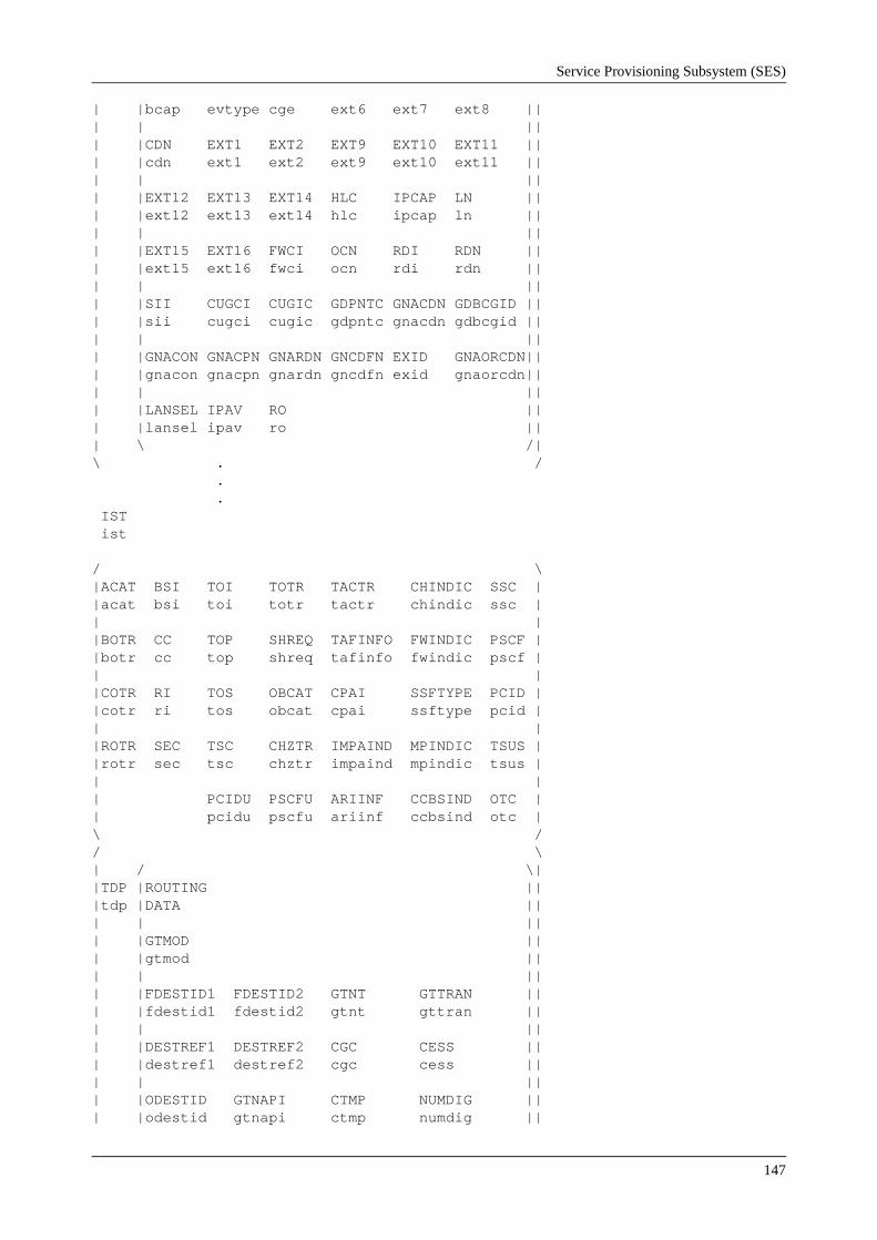
Service Provisioning Subsystem (SES)
147
| |bcap evtype cge ext6 ext7 ext8 || | | || | |CDN EXT1 EXT2 EXT9 EXT10 EXT11 || | |cdn ext1 ext2 ext9 ext10 ext11 || | | || | |EXT12 EXT13 EXT14 HLC IPCAP LN || | |ext12 ext13 ext14 hlc ipcap ln || | | || | |EXT15 EXT16 FWCI OCN RDI RDN || | |ext15 ext16 fwci ocn rdi rdn || | | || | |SII CUGCI CUGIC GDPNTC GNACDN GDBCGID || | |sii cugci cugic gdpntc gnacdn gdbcgid || | | || | |GNACON GNACPN GNARDN GNCDFN EXID GNAORCDN|| | |gnacon gnacpn gnardn gncdfn exid gnaorcdn|| | | || | |LANSEL IPAV RO || | |lansel ipav ro || | \ /| \ . / . . IST ist / \ |ACAT BSI TOI TOTR TACTR CHINDIC SSC | |acat bsi toi totr tactr chindic ssc | | | |BOTR CC TOP SHREQ TAFINFO FWINDIC PSCF | |botr cc top shreq tafinfo fwindic pscf | | | |COTR RI TOS OBCAT CPAI SSFTYPE PCID | |cotr ri tos obcat cpai ssftype pcid | | | |ROTR SEC TSC CHZTR IMPAIND MPINDIC TSUS | |rotr sec tsc chztr impaind mpindic tsus | | | | PCIDU PSCFU ARIINF CCBSIND OTC | | pcidu pscfu ariinf ccbsind otc | \ / / \ | / \| |TDP |ROUTING || |tdp |DATA || | | || | |GTMOD || | |gtmod || | | || | |FDESTID1 FDESTID2 GTNT GTTRAN || | |fdestid1 fdestid2 gtnt gttran || | | || | |DESTREF1 DESTREF2 CGC CESS || | |destref1 destref2 cgc cess || | | || | |ODESTID GTNAPI CTMP NUMDIG || | |odestid gtnapi ctmp numdig ||

IN 2.3 Service Testing Course
148
| | || | |PI DL SFC SCFR || | |pi dl sfc scfr || | | || | |SNS CUNS ADP SSFS || | |sns cuns adp ssfs || | | || | |SKEY || | |skey || | \ /| | / \| | |INVOKE || | |TABLE || | | || | |AGN CGCAT CPN EXT3 EXT4 EXT5 || | |agn cgcat cpn ext3 ext4 ext5 || | | || | |BCAP EVTYPE CGE EXT6 EXT7 EXT8 || | |bcap evtype cge ext6 ext7 ext8 || | | || | |CDN EXT1 EXT2 EXT9 EXT10 EXT11 || | |cdn ext1 ext2 ext9 ext10 ext11 || | | || | |EXT12 EXT13 EXT14 HLC IPCAP LN || | |ext12 ext13 ext14 hlc ipcap ln || | | || | |EXT15 EXT16 FWCI OCN RDI RDN || | |ext15 ext16 fwci ocn rdi rdn || | | || | |SII CUGCI CUGIC GDPNTC GNACDN GDBCGID || | |sii cugci cugic gdpntc gnacdn gdbcgid || | | || | |GNACON GNACPN GNARDN GNCDFN EXID GNAORCDN|| | |gnacon gnacpn gnardn gncdfn exid gnaorcdn|| | | || | |LANSEL IPAV RO || | |lansel ipav ro || | \ /| | . . . . . | | . . . . . | | . . . . . | | / \| |TDP |ROUTING || |tdp |DATA || | | || | |GTMOD || | |gtmod || | | || | |FDESTID1 FDESTID2 GTNT GTTRAN || | |fdestid1 fdestid2 gtnt gttran || | | || | |DESTREF1 DESTREF2 CGC CESS || | |destref1 destref2 cgc cess || | | || | |ODESTID GTNAPI CTMP NUMDIG || | |odestid gtnapi ctmp numdig || | | || | |PI DL SFC SCFR ||

Service Provisioning Subsystem (SES)
149
| |pi dl sfc scfr || | | || | |SNS CUNS ADP SSFS || | |sns cuns adp ssfs || | | || | |SKEY || | |skey || | \ /| | / \| | |INVOKE || | |TABLE || | | || | |AGN CGCAT CPN EXT3 EXT4 EXT5 || | |agn cgcat cpn ext3 ext4 ext5 || | | || | |BCAP EVTYPE CGE EXT6 EXT7 EXT8 || | |bcap evtype cge ext6 ext7 ext8 || | | || | |CDN EXT1 EXT2 EXT9 EXT10 EXT11 || | |cdn ext1 ext2 ext9 ext10 ext11 || | | || | |EXT12 EXT13 EXT14 HLC IPCAP LN || | |ext12 ext13 ext14 hlc ipcap ln || | | || | |EXT15 EXT16 FWCI OCN RDI RDN || | |ext15 ext16 fwci ocn rdi rdn || | | || | |SII CUGCI CUGIC GDPNTC GNACDN GDBCGID || | |sii cugci cugic gdpntc gnacdn gdbcgid || | | || | |GNACON GNACPN GNARDN GNCDFN EXID GNAORCDN|| | |gnacon gnacpn gnardn gncdfn exid gnaorcdn|| | | || | |LANSEL IPAV RO || | |lansel ipav ro || | \ /| \ / [NONE] [EOT DURING PRINTOUT] END
acat A-subscriber category
adp Armed DP indicator When DP9 or DP17 is armed, this indicator specifies how DP9 or DP17 should be armed.
0 Not used
1 DP9 or DP17 armed on incoming leg
2 DP9 or DP17 armed on outgoing leg

IN 2.3 Service Testing Course
150
3 DP9 or DP17 armed on incoming and outgoing leg
agn Additional calling party number This parameter determines whether the additional calling party number should be included when the Service Control Function (SCF) is invoked.
0 Not included
1 Included
2 Included if available
ariinf AssistRequestInstruction INFormation Indicates how to fetch the CorrelationID and SCFID from the call setup message, if the SSF is an Assisting SSF.
0 Assisting SSF The CorrelationID and the SCFID can be received as separate parameters, or can be embedded in the called party number. The CorrelationID and the SCFID are both received in the generic number format.
1 Assisting SSF, user-to-user The CorrelationID and the SCFID are received embedded in the user-to-user information 1 parameter in the call setup message. The CorrelationID and the SCFID are both received in the generic digit format in the user-to-user information 1 parameter.
2 Assisting SSF The CorrelationID and the SCFID are received as separate parameters. CorrelationID is received in generic digit format. The SCFID is received in generic number format.
bcap Bearer capability This parameter determines whether the bearer capability should be included when the SCF is invoked.
0 Not included
1 Included
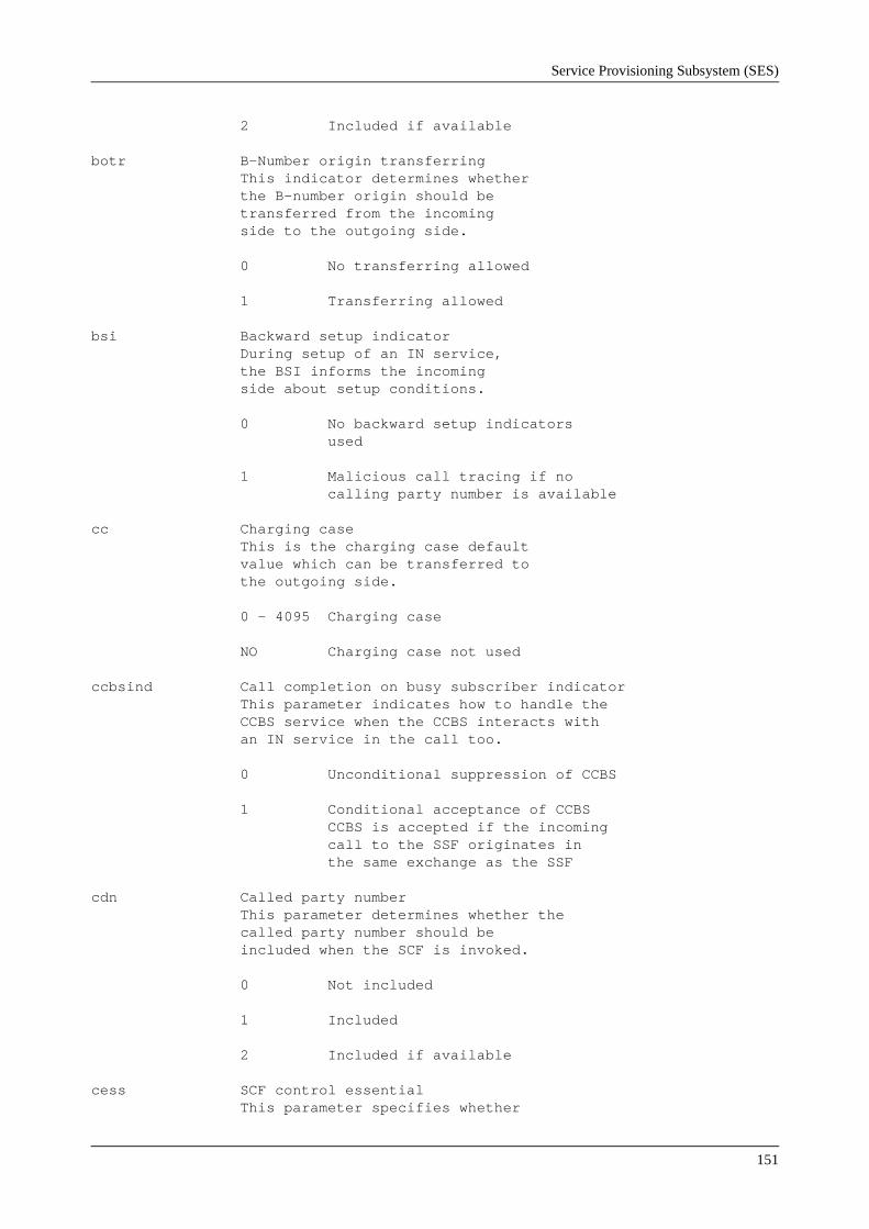
Service Provisioning Subsystem (SES)
151
2 Included if available
botr B-Number origin transferring This indicator determines whether the B-number origin should be transferred from the incoming side to the outgoing side.
0 No transferring allowed
1 Transferring allowed
bsi Backward setup indicator During setup of an IN service, the BSI informs the incoming side about setup conditions.
0 No backward setup indicators used
1 Malicious call tracing if no calling party number is available
cc Charging case This is the charging case default value which can be transferred to the outgoing side.
0 - 4095 Charging case
NO Charging case not used
ccbsind Call completion on busy subscriber indicator This parameter indicates how to handle the CCBS service when the CCBS interacts with an IN service in the call too.
0 Unconditional suppression of CCBS
1 Conditional acceptance of CCBS CCBS is accepted if the incoming call to the SSF originates in the same exchange as the SSF
cdn Called party number This parameter determines whether the called party number should be included when the SCF is invoked.
0 Not included
1 Included
2 Included if available
cess SCF control essential This parameter specifies whether

IN 2.3 Service Testing Course
152
calls in a stable phase are allowed to survive abnormal loss of the dialogue to the SCF.
0 Calls are not allowed to survive
1 Calls are allowed to survive
cgc Call gap criteria
0 No call gap criteria
1 Called address value
2 Gap on service
3 Called address and service
4 Calling address and service
cgcat Calling party category This parameter determines whether the calling party category should be included when the SCF is invoked.
0 Not included
1 Included
2 Included if available
cge Call gap encountered This parameter determines whether the call gap encountered should be included when the SCF is invoked.
0 Not included
1 Included
2 Included if available
chindic Charging indicator Default setting of charge no charge indicator in the ISUP message ANM This indicator must be applied in case the call is handled by basic routing.
0 No indication
1 No charge
2 Charge
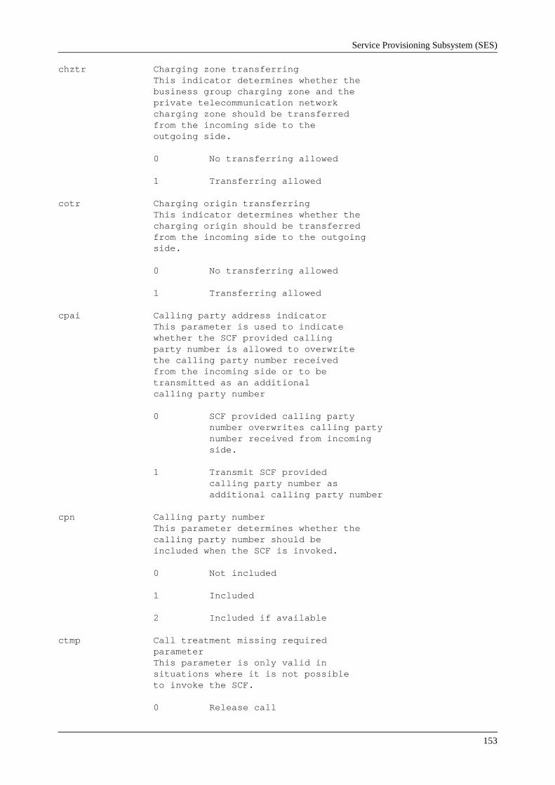
Service Provisioning Subsystem (SES)
153
chztr Charging zone transferring This indicator determines whether the business group charging zone and the private telecommunication network charging zone should be transferred from the incoming side to the outgoing side.
0 No transferring allowed
1 Transferring allowed
cotr Charging origin transferring This indicator determines whether the charging origin should be transferred from the incoming side to the outgoing side.
0 No transferring allowed
1 Transferring allowed
cpai Calling party address indicator This parameter is used to indicate whether the SCF provided calling party number is allowed to overwrite the calling party number received from the incoming side or to be transmitted as an additional calling party number
0 SCF provided calling party number overwrites calling party number received from incoming side.
1 Transmit SCF provided calling party number as additional calling party number
cpn Calling party number This parameter determines whether the calling party number should be included when the SCF is invoked.
0 Not included
1 Included
2 Included if available
ctmp Call treatment missing required parameter This parameter is only valid in situations where it is not possible to invoke the SCF.
0 Release call
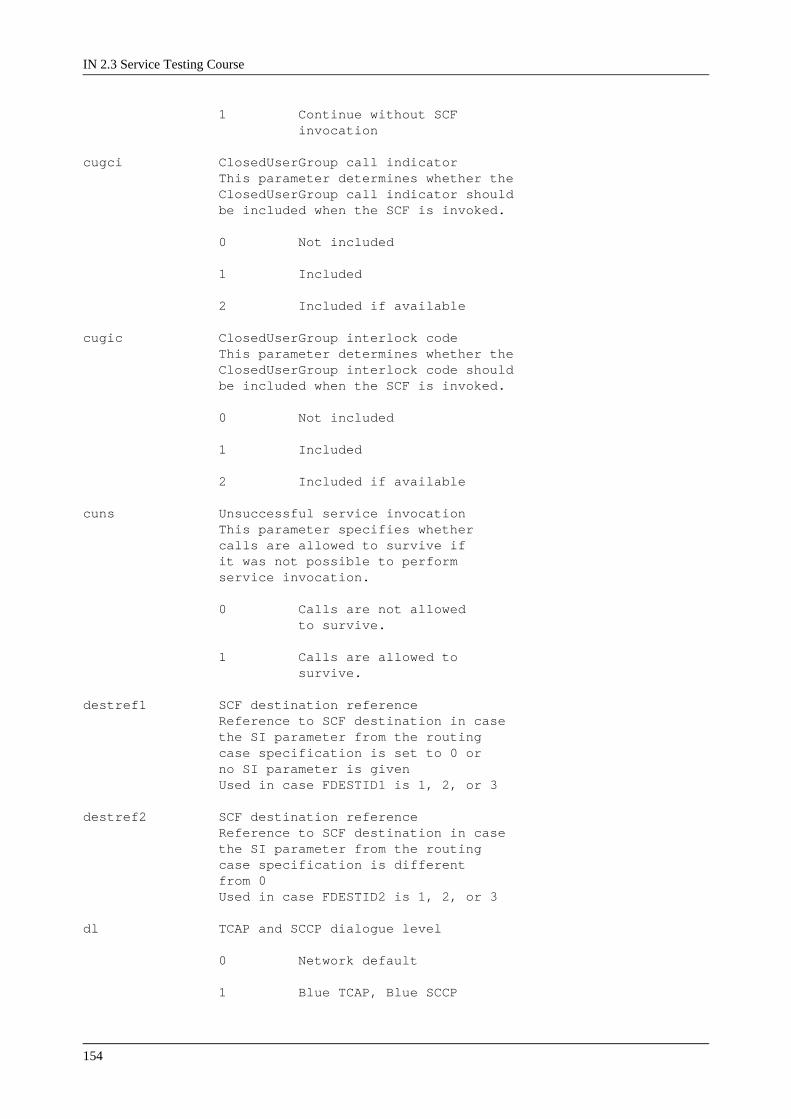
IN 2.3 Service Testing Course
154
1 Continue without SCF invocation
cugci ClosedUserGroup call indicator This parameter determines whether the ClosedUserGroup call indicator should be included when the SCF is invoked.
0 Not included
1 Included
2 Included if available
cugic ClosedUserGroup interlock code This parameter determines whether the ClosedUserGroup interlock code should be included when the SCF is invoked.
0 Not included
1 Included
2 Included if available
cuns Unsuccessful service invocation This parameter specifies whether calls are allowed to survive if it was not possible to perform service invocation.
0 Calls are not allowed to survive.
1 Calls are allowed to survive.
destref1 SCF destination reference Reference to SCF destination in case the SI parameter from the routing case specification is set to 0 or no SI parameter is given Used in case FDESTID1 is 1, 2, or 3
destref2 SCF destination reference Reference to SCF destination in case the SI parameter from the routing case specification is different from 0 Used in case FDESTID2 is 1, 2, or 3
dl TCAP and SCCP dialogue level
0 Network default
1 Blue TCAP, Blue SCCP
Service Provisioning Subsystem (SES)
155
2 White TCAP, Blue SCCP
3 White TCAP, White SCCP
evtype Event type BCSM This parameter determines whether event type BCSM should be included when the SCF is invoked.
0 Not included
1 Included
2 Included if available
exid Exchange identity This parameter determines whether exchange identity should be included when the SCF is invoked.
0 Not included
1 Included
2 Included if available
ext1 Extension 1 This parameter determines whether extension 1 should be included when the SCF is invoked.
0 Not included
1 Included
2 Included if available
ext2 Extension 2 This parameter determines whether extension 2 should be included when the SCF is invoked.
0 Not included
1 Included
2 Included if available
ext3 Extension 3 This parameter determines whether extension 3 should be included when the SCF is invoked.
0 Not included
1 Included
2 Included if available

IN 2.3 Service Testing Course
156
ext4 Extension 4 This parameter determines whether extension 4 should be included when the SCF is invoked.
0 Not included
1 Included
2 Included if available
ext5 Extension 5 This parameter determines whether extension 5 should be included when the SCF is invoked.
0 Not included
1 Included
2 Included if available
ext6 Extension 6 This parameter determines whether extension 6 should be included when the SCF is invoked.
0 Not included
1 Included
2 Included if available
ext7 Extension 7 This parameter determines whether extension 7 should be included when the SCF is invoked.
0 Not included
1 Included
2 Included if available
ext8 Extension 8 This parameter determines whether extension 8 should be included when the SCF is invoked.
0 Not included
1 Included
2 Included if available
ext9 Extension 9 This parameter determines whether

Service Provisioning Subsystem (SES)
157
extension 9 should be included when the SCF is invoked.
0 Not included
1 Included
2 Included if available
ext10 Extension 10 This parameter determines whether extension 10 should be included when the SCF is invoked.
0 Not included
1 Included
2 Included if available
ext11 Extension 11 This parameter determines whether extension 11 should be included when the SCF is invoked.
0 Not included
1 Included
2 Included if available
ext12 Extension 12 This parameter determines whether extension 12 should be included when the SCF is invoked.
0 Not included
1 Included
2 Included if available
ext13 Extension 13 This parameter determines whether extension 13 should be included when the SCF is invoked.
0 Not included
1 Included
2 Included if available
ext14 Extension 14 This parameter determines whether extension 14 should be included when the SCF is invoked.

IN 2.3 Service Testing Course
158
0 Not included
1 Included
2 Included if available
ext15 Extension 15 This parameter determines whether extension 15 should be included when the SCF is invoked.
0 Not included
1 Included
2 Included if available
ext16 Extension 16 This parameter determines whether extension 16 should be included when the SCF is invoked.
0 Not included
1 Included
2 Included if available
fdestid1 Format of SCF address This format parameter is used in case the SI (sending information) parameter from the routing case specification is set to 0, or no SI parameter is given.
0 Local
1 Destination point code and subsystem number
2 Global title
3 Global title and subsystem number
4 Global title service number
5 Global title service number and subsystem number
6 SCFid as global title
7 SCFid as global title and subsystem number
fdestid2 Format of SCF address This format parameter is used in case the SI parameter from the routing case specification is different from 0.

Service Provisioning Subsystem (SES)
159
0 Local
1 Destination point code and subsystem number
2 Global title
3 Global title and subsystem number
4 Global title service number
5 Global title service number and subsystem number
6 SCFid as global title
7 SCFid as global title and subsystem number
fwci Forward call indicators This parameter determines whether the forward call indicators should be included when the SCF is invoked.
0 Not included
1 Included
2 Included if available
fwindic Forwarding indicator This is an indicator used to specify whether the call on the outgoing leg should look like a forwarded call or not.
0 No forwarding
1 Forwarding
gdbcgid Business communication group ID This parameter determines whether the business communication group ID should be included when the SCF is invoked.
0 Not included
1 Included
2 Included if available
gdpntc Private network travelling class mark This parameter determines whether the private network travelling class mark should be included when the SCF is invoked.

IN 2.3 Service Testing Course
160
0 Not included
1 Included
2 Included if available
gnacdn Additional called number This parameter determines whether the additional called number should be included when the SCF is invoked.
0 Not included
1 Included
2 Included if available
gnacon Additional connected number This parameter determines whether the additional connected number should be included when the SCF is invoked.
0 Not included
1 Included
2 Included if available
gnacpn Additional calling party number This parameter determines whether the additional calling party number should be included when the SCF is invoked.
0 Not included
1 Included
2 Included if available
gnaorcdn Additional original called number This parameter determines whether the additional original called number should be included when the SCF is invoked.
0 Not included
1 Included
2 Included if available
gnardn Additional redirecting number This parameter determines whether the additional redirecting number should be included when the SCF is invoked.

Service Provisioning Subsystem (SES)
161
0 Not included
1 Included
2 Included if available
gncdfn Called freephone number This parameter determines whether the called freephone number should be included when the SCF is invoked.
0 Not included
1 Included
2 Included if available
gtmod Global title service number modification Digits can be deleted, and a prefix can be added to the service number used as global title.
gtnapi Global title number plan
0 Reserved
1 ISDN/Telephony (E.164)
2 Data (X.121)
3-15 Spare
NO Parameter is no longer valid
gtnt Global title nature of address Used in case format of SCF address is global title logical, SCFid, or global title service number.
0 Reserved
1 International Number
2 Unknown
3 Subscriber number
4 National Significant Number
5-10 Spare, standard use
11-15 Spare, standard use
NO Parameter is no longer valid

IN 2.3 Service Testing Course
162
gttran Translation type for global title This parameter is used in case format of SCF address is global title, SCFid, or global title service number.
0-254 Translation types
255 Reserved
hlc High layer compatibility This parameter determines whether the high layer compatibility should be included when the SCF is invoked.
0 Included
1 Not included
2 Included if available
impaind Implied A-number indicator This is an indicator used to specify whether the implied A-number shall be used in basic routing when no SCF or SSF provided A-number exists.
0 Do not use implied A-number
1 Use implied A-number
ipav IPAvailable This parameter determines whether the IPAvailable should be included when the SCF is invoked.
0 Included
1 Not included
2 Included if available
ipcap IP SSP capabilities This parameter determines whether the IP SSP capabilities should be included when the SCF is invoked.
0 Not included
1 Included
2 Included if available
ist IN service trigger Current maximum value is defined by SAE 701.
lansel Language selection This parameter determines whether the

Service Provisioning Subsystem (SES)
163
language selection should be included when the SCF is invoked.
0 Not included
1 Included
2 Included if available
ln Location number This parameter determines whether the location number should be included when the SCF is invoked.
0 Not included
1 Included
2 Included if available
mpindic Meter pulse indicator This parameter indicates whether meter pulses should be transferred from the outgoing side to the incoming side.
0 Pass
1 Drop
numdig Number of digits
0 Not relevant for TDP
1-28 Number of called party digits to collect for TDP2 match
obcat Origin of B-category The parameter is used as the origin for B-category analysis, where it is decided whether certain B-subscriber services should be suppressed. OBCAT is used in the block SUA.
ocn Original called party ID This parameter determines whether the original called party ID should be included when the SCF is invoked.
0 Not included
1 Included
2 Included if available
odestid Format of own address
0 Local (SSCP)

IN 2.3 Service Testing Course
164
1 SPC + SSN
2 Global title
3 Global title + SSN
otc Offline tariff class This parameter is only valid for the Spanish market. Used as default tariff class. Is inserted in the TT-record by the IN charging system.
pcid Pointer to first digit of correlationID Pointer to the first digit of the correlationID in the called party number received in the call setup message in an assisting SSF.
3-28 Pointer to first digit of correlationID. PCID must be greater than PSCF.
NO PCID is not used. PSCF must also be NO if PCID = NO.
pcidu Pointer to first octet of correlationID Pointer to the first octet of the correlationID in the the user-to-user 1 information received in the call setup message in an assisting SSF. The correlationID is expected to be received in generic digit format.
3-28 Pointer to first octet of correlationID. PCIDU must be greater than PSCFU + 1.
NO PCIDU is not used. PSCFU must also be NO if PCIDU = NO.
pi Protocol identifier The protocol identifier is used to select the INAP protocol. For each IN service trigger only one charging executor may be pointed out by the PI’s. A charging executor must have subscribed to the protocol identifier. For a description of the values, see Application Information Service Switching Function Changeable Exchange Adaptation.
pscf Pointer to first digit of SCFID Pointer to the first digit of the SCFID in the called party number received in the call setup message in an assisting SSF.

Service Provisioning Subsystem (SES)
165
2-27 Pointer to first digit of SCFID. PSCF must be less than PCID.
NO PSCF is not used. PCID must also be NO if PSCF = NO.
pscfu Pointer to first octet of SCFID Pointer to the first octet of the SCFID in the user-to-user 1 information received in the call setup message in an assisting SSF. The SCFID is expected to be received in generic digit format.
1-26 Pointer to first digit of SCFID. PSCFU must be less than PCIDU - 1.
NO PSCFU is not used. PCIDU must also be NO if PSCFU = NO.
rdi Redirection information This parameter determines whether the redirection information should be included when the SCF is invoked.
0 Not included
1 Included
2 Included if available
rdn Redirection party ID This parameter determines whether the redirection party ID should be included when the SCF is invoked.
0 Not included
1 Included
2 Included if available
ri Route index This parameter is used to select the route used for routing the call.
ro Route origin This parameter determines whether the route origin should be included when the SCF is invoked.
0 Not included
1 Included

IN 2.3 Service Testing Course
166
2 Included if available
rotr Route origin transferring This indicator determines whether the route origin should be transferred from the incoming side to the outgoing side.
0 No transferring allowed
1 Transferring allowed
scfr SCF simulation handling
1 Normal (No simulation)
2 Simulation
3 Message logging
4 Simulation with pretty print
5 Message logging with pretty print
6 Service logic tracing
7 Service logic tracing and message logging
8 Service logic tracing and message logging with pretty print
sec Selection case This parameter indicates which type of CLSM is supported for this call to an IN identifier.
0 Originating CLSM
1 Terminating CLSM
sfc Service filtering criteria
0 No Service filtering analysis
1 Service filtering analysis
shreq Soft or hard request Indicates whether a soft or hard request is to be used to fetch the calling party number and calling party category. If number or category are not available, in own exchange, a hard request will initiate a request backward in the network. A soft request will NOT initiate a request backward.

Service Provisioning Subsystem (SES)
167
0 Hard request
1 Soft request
sii Service interaction indicators This parameter determines whether the service interaction indicators should be included when the SCF is invoked.
0 Not included
1 Included
2 Included if available
skey Service key
sns Service number selection
0 No service number (SN) specified
1 Called party number used as SN
2 Calling party number used as SN
3 Redirecting number used as SN
ssc Signalling system capability This parameter indicates whether the signalling system is capable of transferring correlationID and SCFID in the call setup message between an initiating SSF and an assisting SSF.
0 SCFID and correlationID transferred in separate parameters in generic number format
1 SCFID and correlationID transferred embedded in the B-number in generic number format and as separate parameters in generic number format
2 SCFID and correlationID are transferred as part of the ISUP user-to-user information 1 parameter in generic digit format
3 SCFID and correlationID are sent as separate parameters.

IN 2.3 Service Testing Course
168
CorrelationID is sent in generic digit format. SCFID is sent in generic number format
ssfs SSF simulation handling
1 Normal (No simulation)
3 Message logging
5 Message logging with pretty print
ssftype SSF type This parameter indicates which SSF type will be used when the SCF is invoked.
0 Initiating SSF
1 Assisting SSF
tactr Traffic activity code transferring This indicator determines whether the traffic activity code should be transferred from the incoming side to the outgoing side.
0 No transferring allowed
1 Transferring allowed
tafinfo Tariff information This parameter indicates whether tariff and tariff indicator should be transferred from the outgoing side to the incoming side.
0 Pass in any case
1 Drop in any case
tdp Trigger detection point identifier This parameter identifies to which detection point (DP) the invoke table is connected.
toi Type of indicator The type of indicator contains detailed information for the type of seizure parameter. For a description of the values, see Application Information Traffic Activity Code (4/155 18-ATP 210 11 Uen.).
top Type of procedure The type of procedure contains detailed information for the type of seizure parameter. For a description of the values, see

Service Provisioning Subsystem (SES)
169
Application Information Traffic Activity Code (4/155 18-ATP 210 11 Uen.).
tos Type of seizure The type of seizure indicates a function family group. For a description of the values, see Application Information Traffic Activity Code (4/155 18-ATP 210 11 Uen.).
totr Timesupervision origin transferring This indicator determines whether the timesupervision origin should be transferred from the incoming side to the outgoing side.
0 No transferring allowed
1 Transferring allowed
tsc Type of telecommunication service This parameter is used to identify the telecommunication service code. For a description of the values, see Application Information Traffic Activity Code (4/155 18-ATP 210 11 Uen.).
tsus This parameter contains basic call= related information in order to control the timer for network initiated suspend in the SSP node.
EOT DURING PRINTOUT The operator has cancelled the printout
NONE No data is to be printedFunctionThis printout is received as an answer printout to command SWISP, and lists the above mentioned parameters for IN service trigger identifiers specified in the command. The second line in the printout specifies if the values printed are from the operating or non operating area, as specified by the SWISP command.
Printout TypeAnswer printout
Printout BlockSSFTDA1
IN 2.3 Service Testing Course
170
3.20 Appendix. Description of SSF interfacing APT SubsystemsGroup Switching Subsystem (GSS)The Group Switching Subsystem (GSS) performs switching between time multiplexed buses and sets up paths between telecommunications devices. It also provides timing signals for its own synchronisation and for network synchronisation.The GSS consists of both hardware and software, and it works with other subsystems to switch calls of different types between subscribers - for example local, trunk and transit calls.
The GSS functions are to:
• Select, connect and disconnect speech or signal paths through the Group Switch.
• Supervise disturbance in the hardware.
• Supervise the traffic.
• Supervise the PCM links to the Group Switch
• Maintain a stable clock frequency. This clock frequency is used for synchronisation in the Group Switch, and can also be used to synchro-nise the network.
Charging Subsystem (CHS)Charging is a key function since it is the means of translating network traf-fic into revenue and cost. It is essential that accurate and detailed charging data is available for billing and statistical purposes.
Within AXE, charging and accounting are controlled by the Charging Sub-system (CHS) which is responsible for:
• Basic Charging Function - CHS provides the data to charge subscribers for their calls.
• Accounting - CHS provides the data to settle accounts between cooper-ating network operators (national or international)
• Additional Services - these services are in addition to ‘normal’ call charging. For example, the charging for user-to-user data transfer in signalling messages sent over the D-channel.
Traffic Control Subsystem (TCS)The Traffic Control Subsystem (TCS) is the central traffic control subsys-tem in AXE. TCS consists of software only.
The main TCS functions are divided into:
• Basic Core Functions, including basic call set-up, call supervision and release, and storing of subscriber categories.

Service Provisioning Subsystem (SES)
171
• Analysis Functions, including B-number, A-number and analysis to determine which ISDN service is requested.
• Administrative Functions, performs administration tasks associated with the Analysis functions. For example, they include the commands for changing, handling and printing data in the B-number analysis tables in the DA block.
• Service Functions, including semi-permanent connections and Trunk offering which allows the operator to get into speech position with a busy subscriber to offer an incoming call.
Common Channel Signalling Subsystem (CCS)The Common Channel Signalling Subsystem (CCS) contains both hard-ware and software. Its main function is to handle CCS7 signalling.CCS7 speeds up call set-up time and improves trunk efficiency by sending the signalling information for numerous speech circuits on a few high-speed signalling links. CCS7provides the signalling backbone for IN.
Operation and Maintenance Subsystem (OMS)An AXE exchange is provided with operation and maintenance functions that guarantee a high quality of service OMS is implemented in central and regional software, as well as some hardware.
The main OMS functions are:
• Supervision, which continually supervises the trunk and subscriber lines. if a fault or a disturbance is detected, an alarm is generated.
• Test and Fault Localisation, this contains diagnostic and test functions, which are used in conjunction with alarms and reports to localise faults, both internal and external to the exchange.
• Administration, enables exchange personal to change exchange data, connect and disconnect subscribers and services.
• Statistics, is used for measurement and printout of data such as the vol-ume and type of traffic flowing through the exchange. This information is important for the planning and configuration of exchanges.
Statistics and Traffic Measurement Subsystem (STS)The Statistics and Traffic Measurement Subsystem (STS) collects, stores, process and presents measurement data (statistics) on, for example, traffic flow and network performance. STS is implemented in the Support Proc-essor (SP) but belongs to the APT system. STS consists of software only
The following operations are performed by STS:
• Counters in the traffic system are read and data collected at specific intervals.
• The values of these counters are stored in a measurement database.

IN 2.3 Service Testing Course
172
• At defined intervals report programs read data form the measurement database and produce easy-to-read reports for network management/exchange personnel.
Service Provisioning Subsystem (SES)
173
3.21 Module Summary• SES is divided into two functional elements, 1. Service Switching
Function (SSF) 2. Service Control Function (SCF).
• The SSF provides the set of capabilities required for interaction between the Call Control Function (CCF) and the Service Control Function (SCF) in order to access and process services for subscribers in an Intelligent Network.
• The Service Control function controls the processing of IN services. It contains the service programs, which constitutes the IN services, and provides for the execution of these.
• The IN Service Trigger (IST) is a result of B-number analysis in TCS which, if present, indicates that the call is to be routed to the service switching function (SSF).
• Trigger Detection Points are points in the basic call process where an IN service could be invoked, starting by sending the operation Ini-tialDP.
• Dialogue Control controls how dialogues are initiated, maintained, closed and coordinated by SSF to the SCF.
• IN Call Control is responsible for the interface to the call processing functions of the exchange.

IN 2.3 Service Testing Course
174
3.22 AbbreviationsAD Assisting DialogueBCD Binary Coded DecimalBCSM Basic Call State ModelCID Call Instance DataCS1 Capability Set CS1+ Ericsson superset of CS1CTRTYPE Control typeDM Data ModuleETSI European Telecommunications Standards InstituteFE Functional EntityHD Handoff DialogueID Initiating DialogueIN Intelligent NetworkINAP IN Application ProtocolINM IN Management interfaceINPM IN Protocol ManagerIOG Input Output GroupIP Intelligent PeripheralISDN Integrated Services Digital NetworkLLA Low Level ActionMCS Man-machine Communication SubsystemNCRD Non Call Related DialogueOCS Open Communications SubsystemPHF Protocol Handler FunctionSA Service AdministratorSC Service CustomerSCF Service Control FunctionSCEF Service Creation Environment FunctionSDF Service Data FunctionSDFD SDF DialogueSES SErvice provision SubsystemSIB Service Independent Building BlockSDM Service Data ModuleSL Service LogicSLM Service Logic ModuleSLP Service Logic ProgramSLPI Service Logic Program InstanceSMAS Service Management Application SystemSMF Service Management FunctionSDF Service Data FunctionSRF Specialized Resources FunctionSSCP Service Switching and Control PointSSF Service Switching FunctionSSP Service Switching PointSSI Service Script InterpreterTCAP Transaction Capabilities Application Part

BAT, SAT and NIT
175
4. BAT, SAT and NIT
4.1 Introduction IN services are currently tested in several phases. According to MIND (Method for IN service Development), three test phases can be distin-guished:
1 Basic Test
2 Service Application Test (= Function test in MEDAX and TSE)
3 Network Integration Test (= System Test in MEDAX and TSE)
This module is a description of the test phases, the scope of each phase, the activities to perform in each phase, the documents to use and write per activity and the entry and exit criteria for each activity. The descriptions from the MEDAX and TSE process can be used to extend the descriptions in this module.
Figure 4.1Module objectives
4.2 Test Phases
4.2.1 Product StructureAn IN service roughly consists of 3 parts:
• Service Functionality (SF)
• Service Management System (SMS, also referred to as SAM)
• User Inwindowation (UI)
The complete Service Functionality can be divided into a number of fea-tures. Each feature is implemented by one or more Service Script Logics.
Module Objectives
After completing this module the participants will be able to:
• Explain the aims of BAT, SAT and NIT
• Understand the work procedure for SAT and NIT
• Describe the role, activities and tools associated with IN Service Testing
• Apply acquired skills and knowledge in IN Service testing
IN 2.3 Service Testing Course
176
Up till now a number of different Service Management Systems have been developed: SAMTool and a management system based on APT windows. A third way is to enter data through SMAS. At this moment two new man-agement systems are being developed: one based on Powerbuilder (SMA-Base) and a WWW interface based on Java. All types of management systems can be divided into a number of ‘components’: a (Graphical) User Interface, a database, a transaction handler, and so on.
The Service Functionality and the Service Management System are deliv-ered to the customer with, at least, the following mandatory User Inwindo-wation objects:
• A Service Overview, describing the service from a functional point of view.
• A User’s Guide, describing the use of the SMS.
• A System Administrator’s Guide, containing instructions for installing the SF and the SMS.
It seems obvious that all delivered products are thoroughly tested before they are delivered to the customer.
4.2.2 Test Levels and PhasesAs mentioned in section 1.1 on page 1, MIND distinguishes 3 separate test phases. The first phase, called Basic Test, falls within the responsibility of the designer, while the other two test phases fall within the responsibility of the testers.
When a designer has implemented the code, he must perform a quality check on the implemented code. The check is referred to as a Basic Test. Although you can argue whether this check should be called a Basic Test, a review or a quality check, throughout this module it will be called a Basic Test. Reason is that Basic Test is a common term that is also used in the standard MEDAX and TSE process.
The Basic Test can be divided in two phases:
• A test of the separate blocks of implemented code.
• A test of the interaction between blocks of code making up one product.
The first phase means for SF that all SSLs are deskchecked. For the SMS the separate ‘components’ are tested. For example, the windows are tested separately; no interaction with other windows are tested. The separate User Information objects are reviewed.
During the second phase of the Basic Test, the interaction between fea-tures (SF), ‘components’ of the SMS, and produced customer documenta-tion (UI) is tested. At the end of this phase the complete service functionality, the complete service management system, and the documen-tation is tested as three, more or less, independent parts.
After the Basic Test is completed the separate parts (SF, SMS and UI) are combined to be tested. The SF and the SMS are tested together, either on a real or a simulated STP. The SMS and the UI is also tested in combination.
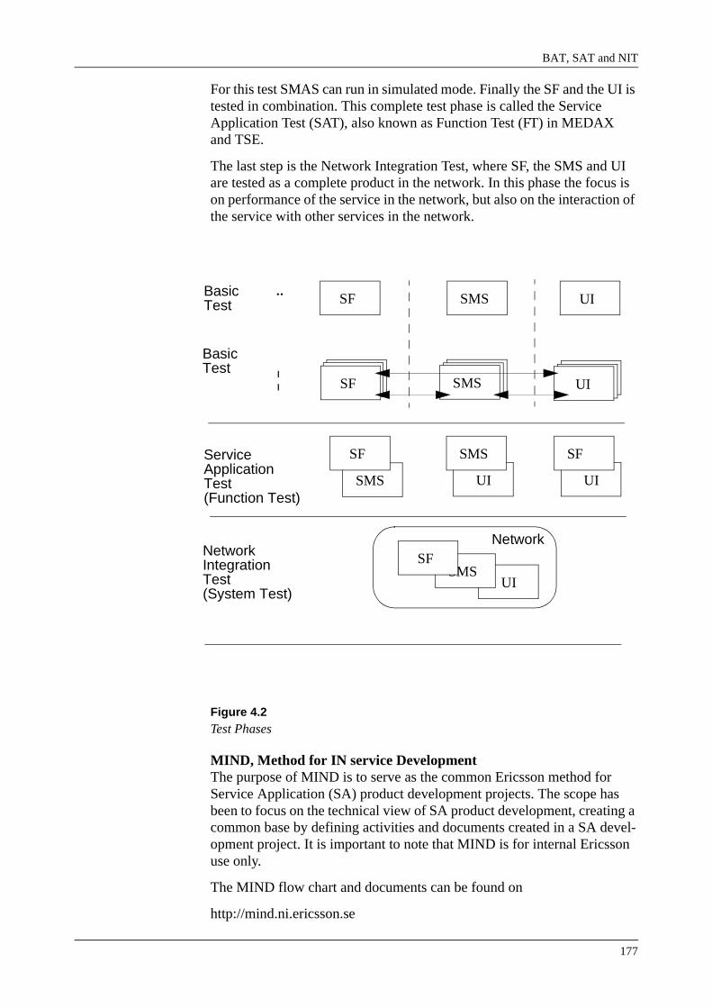
BAT, SAT and NIT
177
For this test SMAS can run in simulated mode. Finally the SF and the UI is tested in combination. This complete test phase is called the Service Application Test (SAT), also known as Function Test (FT) in MEDAX and TSE.
The last step is the Network Integration Test, where SF, the SMS and UI are tested as a complete product in the network. In this phase the focus is on performance of the service in the network, but also on the interaction of the service with other services in the network.
Figure 4.2Test Phases
MIND, Method for IN service DevelopmentThe purpose of MIND is to serve as the common Ericsson method for Service Application (SA) product development projects. The scope has been to focus on the technical view of SA product development, creating a common base by defining activities and documents created in a SA devel-opment project. It is important to note that MIND is for internal Ericsson use only.
The MIND flow chart and documents can be found on
http://mind.ni.ericsson.se
UISMS
UISMS
SAMSAMSFSF
BasicTest
ServiceApplicationTest
NetworkIntegrationTest
SMS UISF
SF SMS
SF SMS
SF
(Function Test)
SAMSAMUI
UI
SF
Network
¨
¦
(System Test)
BasicTest

IN 2.3 Service Testing Course
178
http://mind.ni.ericsson.se
Figure 4.3MIND 2.0
4.3 Basic TestThe primary purpose of the Basic Test is to improve software quality and humanware quality. The Basic Test should detect and eliminate defects as early as possible in the software and humanware life-cycle. Code is checked for conformance to requirements, completeness, consistency and overall correctness. The focus is error detection, rather than correction.

BAT, SAT and NIT
179
The Basic Test is mainly performed by manual source code checking. There are three main methods for performing manual code checking. In each case, the used method depends on the complexity of the code.
1 Desk Check/Code Reading - One or more software engineers (other than the author) independently reviews the code. A checklist is used to ensure consistency. The results are documented in an inspection survey and record. If a Desk Test Checklist exists, it can be substituted for the inspection record. Feedback is given directly to the author or at a meeting.
2 Code Walk-through - A review meeting is hosted and moderated by the author. The emphasis is on error detection and the format is flexible. The participants prepare by reading the code and looking for errors. The results are documented in an inspection survey and record.
3 Code Inspection - A formal and rigorous inspection process in which defect detection, defect elimination, and correction verification is carried out by a small group during the development life cycle. Code inspections use checklists, preparation, well-defined roles, and continual process improvement to maximize error-detection efficiency. The results are documented in an inspection survey and record.
Basic Test execution consists of two phases. In phase 1 individual blocks of implemented code are tested. This phase is called ‘Unit Test’. The second phase focuses on the interface between different blocks of code. This phase is referred to as ‘Integration test’.
It is important to implement the EST, Emulator Service Test on each Service Design Centre (SDC). The emulator will make the Basic Test much more efficient and a lot of faults would be detected much earlier in the Service Development procedure. That would mean that prototyping would be an important part of the design flow.
A Basic Test must be performed on all new and modified code. Code that may be affected by modifications must also be basic tested.
The elements to test should be described in a checklist. Preferably, this checklist must be generic, in order to re-use it in each project.
Faults found during the Basic Test should be reported in the Basic Test Record. After the designer has corrected the fault(s), a new Basic Test must be performed on the modified code. The modified parts must be identified and re-tested.
The designers are responsible for the complete Basic Test.
4.3.1 Entry Criteria BAT phase 1
The following input is required to start the Basic Test Phase 1:
• The Design Specifications (SSD, AAS, UIS) must be approved.
• Checklists for executing a Basic Test must be available.
IN 2.3 Service Testing Course
180
• Approved Service Requirement Specification (SRS).
4.3.2 Basic Test SF - Phase 1
During phase 1 of the Basic Test for SF, the designer/programmer should manually check the code (SSLs) by using one of the above described methods. The procedure to use will be decided by the project team during the feasibility study.
The desk check and review focus on the implementation of one SSL. The integration between SSLs is not formally tested. This is within the scope of the second phase of the Basic Test.
Aspects to consider when desk checking and reviewing a SSL, are:
• Are the correct register numbers used?
• Are the correct data types used?
• Is each variable assigned a value before it is used?
• Are all outlets handled correctly?
• Is the design efficient in terms of SIBs and CDMs?
The test is performed by deskchecking the Service Script Description (SSD) and the Service Function Specifications (SFS). What to check is specified in a checklist.
A Basic Application Test Report, BATR, should be prepared including both test cases and the result of them. Each feature should be tested with the Red Line Trace tool. The BATR should be used as input when preparing the SAT test specifications.
4.3.3 Basic Test SMS - Phase 1
During phase 1 of the Basic Test for SMS, the designer/programmer tests the implemented code. This can be, for example, one window, a procedure, a function or a class. The test concentrates on an isolated block of code. The integration between blocks of code is not formally tested. This is within the scope of the second phase of the Basic Test.
Aspects to consider when desk checking and reviewing a procedure, func-tion, script or class, are:
• How does this correspond to the customer needs and wishes?
• Are the Design Rules and Guidelines followed?
• Is the implementation according to the Design Specification?
• Is the program divided in suitable parts for readability and mainte-nance?
• Is the received input used?
BAT, SAT and NIT
181
• Is the right output generated?
The test can be performed by desk checking and reviewing the imple-mented code or by compiling the code and then executing the compiled code.
Testing the windows of a Graphical User Interface can be split in two parts:
• Coverage Test
• Compliance Test
• Usability Test,
During the coverage test, the designer/programmer starts of by systemati-cally running through as many actions, i.e. menu selections, button push, tick box, etc., as possible.
The compliance test consists of using a checklist to verify that the Graph-ical User Interface (GUI) complies to given guidelines.
The usability test verifies if the GUI meets the Usability Goals which have been defined in the feasibility study.
During phase 1 of the Basic Test SMS, the following areas should be covered when testing each separate window:
• Does the window conform to the SMS Design Rules?
• Do fields on the window behave in the right way (minimum and max-imum value, length)?
• Do buttons and menu options react in the right way?
• Is help text available for every field? Is the text complete and correct?
• Configuration and set-up files should be deskchecked.
The test can be performed by deskchecking and/or executing the imple-mented code.
A checklist specifies the elements to be checked. Such a checklist must be made for every component of the management system. The checklist must be generic, to enable re-use.
4.3.4 Basic Test UI - Phase 1
During phase 1 of the Basic Test for UI, the information designer and repre-sentatives of the SF and SMS groups review the different customer docu-ments.
The scope of this test phase is to check whether the information in the docu-mentation is correct and complete and whether the documentation conforms to the Design Rules and Guidelines.

IN 2.3 Service Testing Course
182
Access to the management system will help when reviewing the documen-tation. However, access to the management system is not required.
Aspects to consider when desk checking and reviewing the customer docu-mentation, are:
• Are the UI Design Rules and Guidelines followed?
• Is the implementation in accordance with the UIS?
• Are descriptions correct (review by SF and SMS)?
• Do the field characteristics comply with SMS specifications?
A checklist must be made stating the aspects to review. The checklist must be made as generic as possible, to enable re-use.
Review remarks are indicated on the checklist or in an inspection record. The information designer is responsible for updating the documentation. After the update, the updated parts should be reviewed once more.
4.3.5 Exit Criteria
The following exit criteria must be met to finalize the Basic Test Phase 1:
• All new and modified code must have been basic tested.
• All ‘testcases’, as listed in the checklist, must be passed.
4.3.6 Basic Test - Phase 2
To support a structured integration test, a test specification containing all test cases must be available. A detailed Test Instruction is not required for this test phase.
Figure 4.4Sub-phases for SF and SMS Integration test
SSL
Feature_1
Procedure
Function
SSLSSL
Class
Feature_2 Component ‘GUI’Component
‘Transaction Handler’
window
window
windowSSL SSL
SF SMS
Complete SMSComplete SF
UI
UG
User Information
SAG EUI
Objects
User’s GuideOn-Line
Complete UI

BAT, SAT and NIT
183
4.3.7 Entry Criteria
The following input is required to start the Basic Test Phase 2:
• Basic Test environment and tools must be established and verified.
• The Design Specifications (SSD, AAS, UIS) must be approved.
• Approved Test Specifications for executing phase 2 of the Basic Test must be available.
4.3.8 Basic Test SF - Phase 2
The second phase of the Basic Test will verify that interfaces between components are correct and that the components interact according to the design. This test phase is typically carried out in steps, where increasingly larger components are integrated.
First, all SSLs making up one feature are combined to be tested. Then all features making up one service are combined to be tested.
This test focuses on whether the service is executing a call in the right way, meaning that the right flow is followed through the features. However, note that the scope of this test is limited to some major functional flows. Not all possible flows are expected to be tested.
The Red Line Trace should be used for this test phase. By defining a number of different subscriptions and specifying input data, it can easily be tested whether the right sequence is followed. Blocking faults in the service and/or in one of the features can be discovered in this way.
Testing of the feature should focus on all major functional flows. To ensure a structured performance of the Integration Test, a Test Specification must be available (included in the BATR), stating all test cases to be executed.
4.3.9 Basic Test SMS - Phase 2
Phase 2 of the Basic Test for SMS focuses on the interaction between different software blocks. All procedures, classes, functions, windows forming a complete Service Management System should be integrated tested.
Testing components consisting of procedures, functions and/or classes should focus on:
• Usability goals fulfilled?
• Are the Design Rules and Guidelines followed?
• Is the implementation of the component according to the Design Spec-ification?
• Is the right input received from either a procedure/class/function or an-other component?

IN 2.3 Service Testing Course
184
• Is the right output generated by the component?
The test can be performed by compiling the code and then executing the compiled code.
The test of the (Graphical) User Interface should focus on:
• Consistent lay-out and behaviour of the windows
• Data correctly inherited from other windows
• User-friendly and easy-to-use management system
• Help-text consistent and helpful
To test the GUI, a User Information designer should be involved to check the GUI on user-friendliness, consistency and ease-of-use.
The way all components should behave is described in the design specifi-cation. This specification can be used as input for the test cases, specified in the Test Specification.
4.3.10 Basic Test UI - Phase 2
Phase 2 of the Basic Test for User Information consists of a review of consistency between the User Information Objects. The User Information Objects are also checked to ensure correctness, completeness and consist-ency. A generic checklist must be created for this purpose.
Aspects to focus on when desk checking and reviewing the customer docu-mentation are:
• Usability goals fulfilled?
• The customer’s needs and demands fulfilled?
• Are the UI Design Rules and Guidelines followed?
• Is the structure of the documentation clear?
• Are the typography and lay-out consistent throughout all documents?
• Are illustrations consistent throughout all documents?
4.3.11 Exit Criteria
The following exit criteria must be met to finalize the Basic Test Phase 2:
• All new and modified code must be basic tested.
• All testcases, as mentioned in the Test Specification, must be passed.
• Basic Test Report must have been prepared.

BAT, SAT and NIT
185
4.4 Service Application Test The Service Application Test (SAT) is the first test phase where all SF, SAM and UI components in the Service Application are integrated and tested as a full product. The focus for SAT is to verify the Service Appli-cation against the requirements according to what is stated in the Service Requirement Specification
The service application test shall include:
• Functionality requirement tests
• Verification of the complete service, using all the Service Application components.
• Performance requirement tests
• Verification of service user loading time
• Call execution time (when needed amount of HW is available, other-wise performed in NIT)
• Number of calls/sec (when needed amount of HW is available, other-wise performed in NIT)
Service Application Test is where functionality is verified from the user’s point of view. That means that it tries out if the Test Object really does what it is intended to do and comprises good usability. Verification of robustness against user related mistakes and external faults is also included here.
More concrete, the Service Application Test focuses on the interaction between SF and the SMS, the SMS and UI and, last but not least, SF and UI. During the SAT/FT all requirements as specified in the SRS and possible Change Requests, must be verified. Whenever possible, capacity tests are also within the scope of the Service Application Test. However, if capacity tests cannot be executed it this test phase, they will be moved to the Network Integration Test.
In the Service Application Test every detected fault generates a Trouble Report. Formal Trouble Reports must always be written in order to get a correct statistical evaluation of the project and confirm that no detected faults are dropped. Trouble Reports are written in TRtool.
The complete Service Application Test is the responsibility of the testers.
4.4.1 SF-SMS Test
For the SF-SMS Test, the SMS is used to enter data that is needed to execute the service. When the data is defined, calls can be set up to test the service functionality. The User Information is used as a help for the testers; the documentation is not formally tested.
The SF-SMS test is executed on a either a real STP or a simulated one (Simulated Function Test), where calls can be made.
This test is mainly a requirement based test, meaning that all SF require-ments must be tested. A Test Specification and a Test Instruction are used

IN 2.3 Service Testing Course
186
to ensure a structured and controlled way of testing. Testing of the SMS requirements is done in the SMS-UI test.
For the SF-SMS test extensive knowledge of the service is required. It is recommended that the SF-SMS testers are involved in phase 2 of the Basic Test for SF. The testers can then get a good view of the structure of the service.
4.4.2 SMS-UI Test
The SMS-UI test can be divided in two parts: testing the SMS requirements and testing the UI requirements. The SMS requirements are tested here and not in the SF-SMS test, because most test cases for the SMS can be executed without the use of an STP.
All SMS requirements are tested on their correct implementation and whether data entered in the SMS is sent to the correct data modules in SMAS. Testing the usability of the SMS is also within the scope of the SMS-UI Test.
Besides the SMS requirements, the UI requirements are tested on their correct implementation and the relation between the SMS and the docu-mentation is tested: does the documentation exactly describe how the SMS works. Aspects of the documentation to be tested are:
• Are the step-by-step instructions in the documentation correct and complete?
• Are all functions of the SMS described in the documentation?
• Does the text, in combination with the illustrations, give all information needed to use the SMS?
• Is the reader guided through the documentation in the right way?
The SMS-UI test is executed with SMAS in simulated mode. A Test Spec-ification and a Test Instruction are used to ensure a structured and controlled way of testing.
The SMS-UI test must be performed by the Service Application Testers. The testers must have knowledge strategies to test user interfaces.
4.4.3 SF-UI Test
The SF-UI test mainly concerns the installation instructions of SF: do the installation instructions exactly describe how the SF can be installed. To test this, the step-by-step instructions must be strictly followed.
A Test Specification and a Test Instruction are used to ensure a structured and controlled way of testing.
The SF-UI test must be performed by the Service Application Testers. They do not need to have service specific knowledge. As the installation instruc-

BAT, SAT and NIT
187
tions are written for an audience with knowledge of Unix and SMAS, the testers are expected to have this knowledge too.
Test environmentThe tests can be performed in different environments, and without access to the complete network environment. The AXE test environment must be equipped with:
• Proper software generation according to Service Requirement Specifi-cation (SRS). A software generation, dump, which is maintained either as a Product Line dump or as an AS containing the proper generation of the IN software. Which software generation that is required shall be stated in the SRS. It must be stated if the Service Application requires specific corrections or specific products.
• Limited hardware For the SAT, only limited hardware shall be required. The tests ought to be able to perform in a single node, unless the Service Application requires more than one node. The basic hardware setup implies service access using either LIC or BL.
Entry Criteria
The following input is required to start the Service Application Test:
• Approved Service Application Test Plan
• Service Application Test environment must be established and veri-fied.
• Approved Service Application Test Specifications and Test Instruc-tions must be available.
• All Basic Test cases must be passed.
• Deviation Descriptions and Product Revision Information must be available.
Exit Criteria
The following exit criteria must be met to finalize the Service Application Test:
• All errors found are reported.
• All testcases, as mentioned in the Test Specification, must be passed.
• Input to Service Application Test Report has been provided.
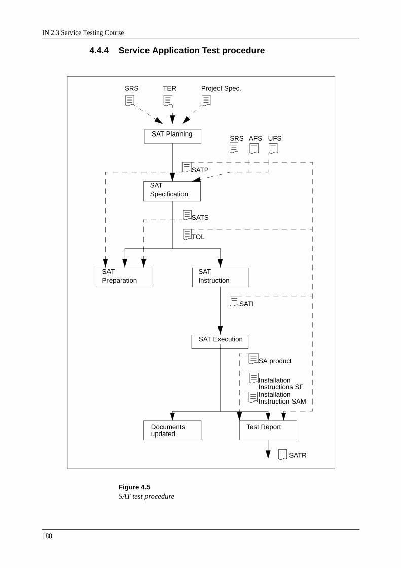
IN 2.3 Service Testing Course
188
4.4.4 Service Application Test procedure
Figure 4.5SAT test procedure
Documents
SAT Execution
SAT Planning
SAT Instruction
SAT Preparation
SAT Specification
SRS AFS UFS
SRS TER Project Spec.
SATS
TOL
SATI
Test Report
SATR
updated
Installation Instruction SAM
SATP
SA product
InstallationInstructions SF

BAT, SAT and NIT
189
Test PlanningWithin this activity, the basis for Service Application Test (SAT) is defined. This implies descriptions of tools to be used (for example simula-tor/emulator), test reports to be written and personnel required for testing.
An analysis is made of the requirements and other preconditions which will affect the scope of SAT. In addition to the Service Requirement Spec-ification (SRS), check the general test aspects that have been considered in the TEchnical Report (TER) during the prestudy phase.
To plan for SAT, a number of issues have to be considered:
• Test analysis giving the scope of test, estimation of man-hours for test design and execution, estimate time and resources for Test Configura-tion Management (TCM), specify if tests are excluded and subjects for special attention.Note: Should some performance tests not be possible to execute in SAT due to HW limitations, this must be communicated to the Network Inte-gration Test (NIT) test as early as possible!
• Initial TCM activities including test plant booking where requirements on AXE SW, AXE HW, SMAS environment and other environments must be specified. This is a critical activity which must be initiated as early as possible in order to get access to a testsite with the proper setup.
• Test decision where the object is to:
- Decide the scope of the tests that are to be performed.
- Approve the cost estimate for the tests.
Input
Service Requirement Specification, SRS
TEchnical Report, TER
Project information
Output
Service Application Test Plan, SATP
SAT SpecificationThe purpose of the Service Application Test Specification (SATS) activity is:
• To give an overview of the test environment, necessary equipment, test tools and their usage.
• Specify the test configuration and indicate if any deviations from a standard SAT configuration are required.
The way to perform each test case defined in the SAT plan shall be described and compiled into a SAT Specification where each test case is numbered. A test case is one of the following categories:

IN 2.3 Service Testing Course
190
• Requirement based test to verify behaviour and performance as stated in the requirements.
• Design based test to verify changes made to the SF, SAM and UI parts not related to any requirement.
• Miscellaneous test to verify aspects not covered in requirement based or design based tests, e.g. user friendliness.
In addition to the Service Application Test Specification (SATS), a Test Object List (TOL) used for checking the progress during test execution should be created. The TOL is a matrix with each test case against all rele-vant information for that test case.
Input
Service Application Test Plan, SATP
Service Requirement Specification, SRS
Service Function Specification, SFS
Administration Function Specification, AFS
User information Function Specification, UFS
Output
Service Application Test Specification, SATS
Test Object List, TOL
SAT InstructionThe purpose of a Service Application Test Instruction (SATI) is to give a detailed, step-by-step description of how each test case should be exe-cuted, and the expected result of each action. Depending on the complex-ity, several SAT instructions may be created.
Each SAT instruction should also contain information about the test envi-ronment, part of the exchange configuration involved, and manual prepa-rations or modifications needed. All modifications must be restored after the test.
Input
Service Application Test Specification, SATS
Test Object List, TOL
Output
Service Application Test Instructions, SATI
For an example of what the content list of a SATI would look like se figure 1.6, figure 1.7. shows an example of a test case layout according to MIND:

BAT, SAT and NIT
191
Figure 4.6SATI content list example
Freephone
Contents 1 Preparations 1.1 Test Environment 1.2 Data for loading of Freephone 1.3 Data for removal of Freephone
2
Requirement-Based tests 2.1 Ordinary calls (Successful calls) 2.2 Ordinary calls (Unsuccessful calls) 2.3 Modification calls (Successful calls) 2.4 Modification calls (Unsuccessful calls) 2.5 Call for access to other services (Successful calls)
3
Design based tests 3.1 Normal user reactions 3.2 Abnormal user reactions
4
References

IN 2.3 Service Testing Course
192
Figure 4.7A Test case example
SAT PreparationThe objective of Service Application Test (SAT) preparation is to setup the test plants in accordance with the SAT plan. This includes AXE, SAM-servers, workstations, and other HW needed in addition to the standard setup.
The setup should be conducted using correct versions of AXE software and SMAS. Exchange data should be loaded (and modified if necessary), parameter corrections and service related corrections should be loaded.
All test tools specified shall be made available.
Before the preparation is ready, the basics shall be verified, for example by making some test calls.
Input
Service Application Test Specification, SATS
Service Application Test Plan, SATP
Output
Test site ready for execution
2.1.1 Successful call - connection to 800011
ACTION: Dial the access number for the service 30 12345678.
RESULT: The phone with the number 800011 rings.
ACTION: Answer the phone and check that you are in speech position.
RESULT: Speech path okey.
ACTION: Onhook all phones and check that no devices are hanging:
> TOBJI:ALL;
RESULT: No devices are hanging.
COMMENT: -
Calls from one of the A-numbers 1-4. Make sure that 800011 will be chosen by the load distribution function.

BAT, SAT and NIT
193
SAT ExecutionDuring test execution, the progress should be monitored by the Test Man-ager, who also reports to the main project. Operative decisions concerning the test execution are made by the Test leader. Please note that it is not only the functions and characteristics of the service that should be tested, but also instructions such as Installation Instructions.
The exchange data files should be stored and a Service Application Test Report should be written. When the SA product has passed the service application test and all product documents have been updated, they are stored in GASK.
It is important that experiences and opportunities for improvement are identified and described before the SAT execution activity is finished.
Input
SA product
Installation Instructions, II (SF)
Installation Instructions, II (SMS)
Service Application Test Instructions, SATI
Test Object List, TOL
Service Application Test Plan, SATP
Output
Service Application Test Report, SATR
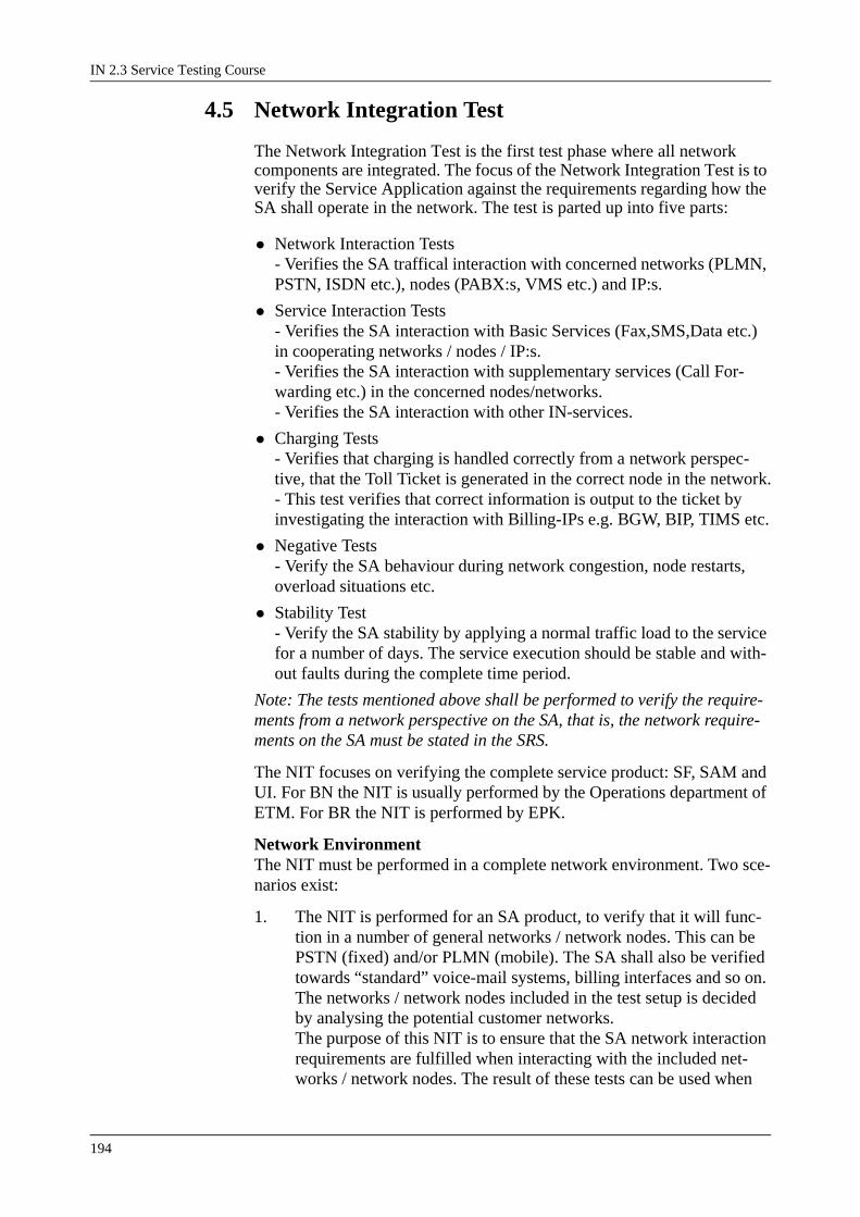
IN 2.3 Service Testing Course
194
4.5 Network Integration Test
The Network Integration Test is the first test phase where all network components are integrated. The focus of the Network Integration Test is to verify the Service Application against the requirements regarding how the SA shall operate in the network. The test is parted up into five parts:
• Network Interaction Tests- Verifies the SA traffical interaction with concerned networks (PLMN, PSTN, ISDN etc.), nodes (PABX:s, VMS etc.) and IP:s.
• Service Interaction Tests- Verifies the SA interaction with Basic Services (Fax,SMS,Data etc.) in cooperating networks / nodes / IP:s.- Verifies the SA interaction with supplementary services (Call For-warding etc.) in the concerned nodes/networks.- Verifies the SA interaction with other IN-services.
• Charging Tests- Verifies that charging is handled correctly from a network perspec-tive, that the Toll Ticket is generated in the correct node in the network.- This test verifies that correct information is output to the ticket by investigating the interaction with Billing-IPs e.g. BGW, BIP, TIMS etc.
• Negative Tests- Verify the SA behaviour during network congestion, node restarts, overload situations etc.
• Stability Test- Verify the SA stability by applying a normal traffic load to the service for a number of days. The service execution should be stable and with-out faults during the complete time period.
Note: The tests mentioned above shall be performed to verify the require-ments from a network perspective on the SA, that is, the network require-ments on the SA must be stated in the SRS.
The NIT focuses on verifying the complete service product: SF, SAM and UI. For BN the NIT is usually performed by the Operations department of ETM. For BR the NIT is performed by EPK.
Network EnvironmentThe NIT must be performed in a complete network environment. Two sce-narios exist:
1. The NIT is performed for an SA product, to verify that it will func-tion in a number of general networks / network nodes. This can be PSTN (fixed) and/or PLMN (mobile). The SA shall also be verified towards “standard” voice-mail systems, billing interfaces and so on. The networks / network nodes included in the test setup is decided by analysing the potential customer networks.The purpose of this NIT is to ensure that the SA network interaction requirements are fulfilled when interacting with the included net-works / network nodes. The result of these tests can be used when
BAT, SAT and NIT
195
selling the SA.
2. The NIT is performed as a system test, to verify that the SA func-tions as required in a specific customer network. The test environ-ment (trunk interfaces, parameter settings etc.) must be set-up as close as possible to the customer network. If a NIT of the first type has already been performed this NIT will only verify customer spe-cific interaction requirements not included in the first NIT.
The NIT must be performed with the proper software generation in every network node included in the test configuration. The NIT is only applica-ble for one software generation network configuration.
Entry Criteria
The following input is required to start the Network Integration Test:
• Approved Network Integration Test Plan
• Network Integration Test environment must be established and veri-fied.
• Approved Network Integration Test Specifications must be available.
• All Service Application Test cases must be passed.
• Deviation Descriptions and Product Revision Information must be available.
• All Trouble Reports from previous test phases are corrected or have proven workarounds
• All preliminary User Documentation
Exit Criteria
The following exit criteria must be met to finalize the Network Integration Test:
• All errors found are reported.
• All testcases, as mentioned in the Network Integration Test Specifica-tion, must be passed.
• Input to Network Integration Test Report has been provided.
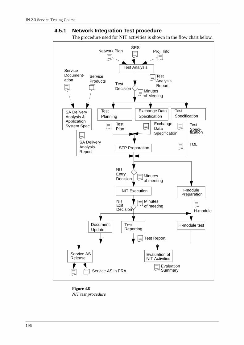
IN 2.3 Service Testing Course
196
4.5.1 Network Integration Test procedureThe procedure used for NIT activities is shown in the flow chart below.
Figure 4.8NIT test procedure
Test Analysis
Network PlanSRS
Proj. Info.
Test Planning
STP Preparation
Test Specification
Exchange Data Specification
NIT Execution
TestDecision
Minutesof Meeting
TestAnalysisReport
TestSpeci-fication
ExchangeDataSpecification
TOLSA DeliveryAnalysisReport
TestPlan
SA DeliveryAnalysis &
NITEntryDecision
Minutesof meeting
ServiceDocument-ation
ServiceProducts
Document H-module testUpdate
TestReporting
H-modulePreparation
Evaluation ofNIT Activities
ApplicationSystem Spec.
Minutesof meeting
Service ASRelease
NITExitDecision H-module
Test Report
EvaluationSummaryService AS in PRA

BAT, SAT and NIT
197
Test AnalysisThe Test Analysis is performed to analyse the technical scope of the planned NIT. The amount of work required to perform a test according to this scope is also analysed. A suggested test environment including all necessary network components to perform the test with the required qual-ity should be defined on block level.
Technical assistance from System Experts should be available to analyse certain complicated issues. The Test Leader should focus on the technical issues. The Project Manager should focus on project related issues like the estimation of man-hours and risks.
Input documents:
• A Network Plan of the target network. This plan should indicate the nodes and networks cooperating with the IN service. The interface used towards these nodes and networks should also be stated. If a customer specific Network Plan is unavailable a general network configuration should be used.
• A Service Requirement Specification with a number of requirements affecting network interaction.
• Project information stating the requirements on the NIT test period like required quality, auxiliary networks included by strategic reasons etc.
• Previous Test Analysis Reports, NIT Evaluation summaries and Min-utes of the Test Decision Meetings from other test projects should be used as a source of information.
The Test Analysis Report, which is the output of the Test Analysis, must state the following:
• A list of all included test cases. This list should be made with headings according to the standard list of test categories for NIT (Network Inter-action, Service Interaction, Charging, Negative and Stability tests). If possible, priorities shall be defined for the test cases, at least in two lev-els: high priority and low priority. If available a reference to the rele-vant network interaction requirement should be stated together with each test case.
• Estimate required man-hours for the activities during the following test period (The activities are; Test planning, Test Specification, Exchange Data Specification, STP preparation and NIT execution). The man-hours shall be calculated using information accumulated from previous test projects (x man-hours per test case).
• Excluded tests should be explicitly stated together with the reason why they where excluded ("excluded tests" means tests that are included in the normal scope of NIT but are not included in this particular test project).
• Indicate risks and opportunities that have been found during the analy-sis.

IN 2.3 Service Testing Course
198
Test PlanningThe Test Planning can be divided into three sections: test, TCM and qual-ity. It is performed to allocate the necessary STP resources for the NIT, plan the test execution, plan the TCM activities and also to outline quality considerations. The Test Plan for the NIT shall be prepared by the Project Manager and the TCM responsible in cooperation.
As input to the Test planning the following should be used:
• The Test Analysis Report. This document should indicate the various network components needed in a suitable STP environment.
• Project Quality Plan. This document will outline the quality require-ments for the project.
The objective of the Test planning is:
• To describe all components included in the test plant. This is normally the first activity to perform. It is a critical activity since test plants are normally heavily booked. SW and HW may have to be purchased / rented and this has to be planned well in advance. When booking, a number of test requirements must be taken into account like:- AXE SW and HW requirements.- SMAS SW and HW requirements.- Other Network component requirements (PABX, BGW, VMS etc.)- The number of test phones (mobile, fixed).- The number of AT terminals.- A-law or u-law speech coding.- Test position and tools like UNIX applications, FIOL, PlexView, DocView etc.- Other test tools like TURBO-7 signalling generator.
• Book the required STP configuration.
• To state the SW level for the included nodes in the test plant.
• To plan the test execution phase. This should be in the form of a time plan and routines to follow for e.g. trouble shooting.
• To state the NIT test organisation and the procedures for test execution.
The objective of the TCM planning is:
• To describe the generation handling procedures to follow. This allows the introduction of changes to the test environment in an organised and traceable way. Items described should be how to use the Log-Book, how to handle emergency corrections and how to handle product updates. Handling and labelling of the AXE-dumps, SMAS-dump etc. should also be described.
• To state how trouble reporting shall be handled e.g. by using MHS. If MHS is used, state TR-identities etc.
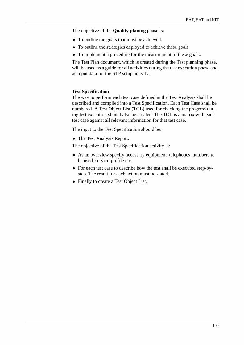
BAT, SAT and NIT
199
The objective of the Quality planing phase is:
• To outline the goals that must be achieved.
• To outline the strategies deployed to achieve these goals.
• To implement a procedure for the measurement of these goals.
The Test Plan document, which is created during the Test planning phase, will be used as a guide for all activities during the test execution phase and as input data for the STP setup activity.
Test SpecificationThe way to perform each test case defined in the Test Analysis shall be described and compiled into a Test Specification. Each Test Case shall be numbered. A Test Object List (TOL) used for checking the progress dur-ing test execution should also be created. The TOL is a matrix with each test case against all relevant information for that test case.
The input to the Test Specification should be:
• The Test Analysis Report.
The objective of the Test Specification activity is:
• As an overview specify necessary equipment, telephones, numbers to be used, service-profile etc.
• For each test case to describe how the test shall be executed step-by-step. The result for each action must be stated.
• Finally to create a Test Object List.

IN 2.3 Service Testing Course
200
Figure 4.9NIT Specification
BAT, SAT and NIT
201
Exchange Data SpecificationThe Exchange Data Specification activity is performed in order to create a document describing the service oriented exchange data. The document shall define the exchange data and parameters needed to get the SA opera-tional in the network included in the NIT scope. This may cover data changes in i.e. the SSP, MSC, PABX and other nodes. The following items should be handled in the document:
• Exchange data to get the service in operation. This will include service triggering data, valid subscriber categories, B-no. analysis data, charg-ing data etc.
• Parameter corrections needed to support charging etc.
• Service related corrections needed in the SSP or in the other network nodes.
STP PreparationThe goal of this activity is to setup the System Test Plant (STP) according to the network configuration described in the Test Plan. The exchange data for the service should be setup using the Exchange Data Specification.
• The setup of each node should be done with the relevant AXE software release (according to the Test plan). The basic exchange data should be loaded and on top of this the service related exchange data. Parameter corrections and service related corrections necessary for the service should be loaded.
• When the STP preparations are finalised the TCM responsible should be informed about the configuration of each node. The software backup, a software record and the exchange data files should all be stored according to the routines stated in the Test Plan. Note that a SMAS backup without any service should also be stored.
Note: This "starting point reference" including all nodes in the setup is very important to produce in order to have a stable "fall-back" during test execution. All experience shows that this is really needed in the complex testing environment that the NIT concept creates.
SA Delivery Analysis and Application System SpecificationThe Application System Specification will take place as part of the NIT, the procedure involves registering the service application system and related documentation in PRIM.
The SA Delivery Analysis is performed in order to verify that a complete delivery has been received from the design department. As a result of the analysis a short summary should be written describing the state of the delivery. A number of items should be checked:
• Verify that all service products have been delivered and that these prod-ucts are in a released state.
• Verify that all applicable SA documentation to install, test, deliver and

IN 2.3 Service Testing Course
202
maintain the service is delivered and in a released state.
Network Integration Test ExecutionDuring this phase of the project the NIT testing will be executed. The NIT shall include Network Interaction tests, Service Interaction tests and Charging tests, Negative tests and Stability tests unless otherwise stated as excluded in the Test Analysis Report. The tests will be carried out accord-ing to procedures outlined in the test plan. The Test Object List (TOL) will be updated throughout the test execution phase.
H-Module PreparationThe H-Module is a binder containing all information related to the installa-tion of a service product. The binder should contain:
• Installation Test Specification.
• Demonstration Test Specification.
• Acceptance Test Specification.
All the above documentation will ensure that the service product can be installed and made operational in a customer site. The Demonstration and Acceptance Test Specification outlines the procedure to get the service product operational. The H-Module may be part of the customer documen-tation package.
Test ReportThis document should be completed by the testleader and approved by the project manager. It should describe the results of the NIT in detail and may contain information like:
• Test Object
• Test Result
• List of failed Test Cases (with explanation).
• Completed Test Object list (TOL).
• List of Service related corrections.
H-Module TestThe Installation, Demonstration and Acceptance Test Specifications should be fully tested to ensure the service can be made fully operational on delivery to the customer site as quickly as possible.
In order to complete these tests correctly it is necessary to execute a com-plete maiden installation of the Service Application within the test config-uration.

BAT, SAT and NIT
203
Service Application System ReleaseThe NIT execution phase is now complete. The Service AS is now fully tested with all relevant documentation updated and reviewed. The Service AS is now ready for delivery. The Service AS may now be released with all documentation complete and approved.
The service product may be market specific and as such will be released as PRA. It will then become part of a First Office Application (FOA) or Delta delivery. In this situation the Industrialisation activity is not complete as the Service Delivery procedure is also the responsibility of the Industriali-sation project, this procedure will be described in the next section.
The service product may also be a general product for "off the shelf" sales. In which case the Industrialisation project activities are now complete. Some parts of the NIT may need to be repeated for this product under mar-ket conditions when they are known but this is not always the case.
Evaluation of NIT ActivitiesAll personnel will be involved in this phase of the project. They will each be responsible for submitting their opinions on how the project could have been improved, new test tools or better procedures perhaps. This Evalua-tion summary should also contain statistical information about the project resources, man-hours, STP and test cases for example.
This information will allow for better planning in future projects and will give statistical output on time periods involved for projects.

IN 2.3 Service Testing Course
204
4.6 Delivery ProcedureThe procedure used for Delivery activities is shown in the flow chart below. Each activity will be described separately in the following chapters
Figure 4.10Delivery procedure
4.6.1 GeneralFor a Delta or FOA delivery the installation and initial market support are part of the Industrialisation procedure. A Delta delivery is the customisa-tion of an existing product for re-release in a new market application. This is due to the fact that the NIT was performed as a system test to verify the SA functions for a specific customer network. Parts of the NIT may then need to be repeated in the future should the service product be sold in a different market environment.
4.6.2 Customer PackageThis process customises a service product for a specific customer market. Each customer will have different requirements and these must be taken into consideration when the service product is being delivered. Some cus-
CustomerPackage
Installation
InstallationTest
Acceptance
Service AS in PRA/PRB
FOA Support
Yes
No
Handoverto PLM
Service AS in PRB ?

BAT, SAT and NIT
205
tomers will require assistance with network configuration, they may require all the service product documentation whereas other customers may not.
4.6.3 InstallationUsing the Installation Instruction as prepared for the H-Module the service product is loaded into the customer network. Any modifications to the cus-tomer network will be completed to ensure the service product will func-tion correctly. Details and decisions regarding the installation will take place between the project manager, testleader and customer representa-tives. Before the installation all relevant documentation as specified in the customer requirements will be given to the customer for inspection.
4.6.4 Installation TestThis test is completed after the installation. The entry criteria are:
• Correct HW and SW generations available
• H-Module
• Relevant Docview and Plexview
• Network information
• Service product information
The installation test activity is performed according to the test plan and the exit criteria are:
• All tests are completed and signed off
• A summary of all trouble reports, their classifications and status must exist
The project manager and the test leader are responsible to ensure the entry and exit criteria are met.
4.6.5 AcceptanceThis phase uses the Demonstration and Acceptance test specifications from the H-Module. The service product is verified in the customer net-work using a small cross section of test cases from the NIT. The network configuration and exchange data may need to be modified for these tests to be completed. Any service or market parameter corrections will also be loaded at this time.
4.6.6 First Office Application (FOA) supportAfter the acceptance is complete the NIT team (or part thereof) will be responsible for the support of the product until the status changes to PRB. The product is then handed over to PLM and the NIT responsibilities are finally complete.

IN 2.3 Service Testing Course
206
4.7 Module SummaryAn IN service roughly consists of 3 parts:
• Service Functionality (SF)
• Service Management System (SMS (SAM))
• User Inwindowation (UI)
The table below shows the test phases, the type of document that describes the tests to be executed and the way to handle Trouble Reports.
Test Phase Document Trouble Reports
Remarks
Basic Test - Phase 1 Checklist Checklist
Basic Test - Phase 2 Test Specifica-tion
SCN Tool SF: Use Red Line Trace
Service Application Test
Test Specifica-tion and Test Instruction
TR Tool SF-SMS: test on STP or use emulator
Network Integration Test
Test Specifica-tion
TR Tool

BAT, SAT and NIT
207
Glossary
AAS Administrative Application Specification
BAT Basic Test; the first test phase, performed bydesigners/programmers
BGW Billing Gateway
FOA First Office Application
IP Information Provider
ISDN Integrated Services Digital Network
GUI Graphical User Interface
MEDAX Method products for AXE 10 Development and Maintenance
MIND Method for IN service Development
NIT Network Integration Test; called System Test inMEDAX and TSE.
PABX Private Automatic Branch Exchange
PSTN Public Switched Telephone Network
PLMN Public Land Mobile Network
SA Service Application
SAT Service Application Test; called Function Test inMEDAX and TSE.
SCNTool An Ericsson tool used to register fault found duringphase 2 of the Basic Test.
SDC Service Design Centre
SF Service Functionality; the implemented service logic inSMAS.
SFS Service Function Specification
SMABase A new SMS, developed for the fixed market (BN),based on Powerbuilder.
SMAS Service Management Application System; the application used to implemented the service logic.
IN 2.3 Service Testing Course
208
SMS Service Management System; the user interface implemented on top of SMAS for entering subscriptiondata.
SRS Service Requirement Specification
SSD Service Script Description
SSL Service Script Logic
STP System Test Plant
TCM Test Configuration Management
TER Technical Report
TOL Test Object List
TRTool An Ericsson tool to register trouble reports.
TSE TMOS development Support Environment
UI User Inwindowation
UIS User Information Specification
VMS Virtual Memory System

IN Charging
209
5. IN Charging
5.1 Introduction
5.1.1 ObjectivesTo Network Operators, Charging is the most important function of any network. There is little point in providing services to customers unless these services can be charged in order to generate revenue. For Intelligent Networks, charging is even more important, as the raison d’etre of IN services is to generate additional revenue. Furthermore, IN services require more flexible and innovative charging methods than that tradition-ally used for Plain Old Telephony Services (POTS).
Figure 5.1Module Objectives
In this module, we will review how charging takes place in an AXE exchange, and explain some of the more typical information fields con-tained in a TT (Toll-Ticket) record.
We will then examine how charging takes place in an Intelligent Network, including the roles of the SCP and SSP in charging. We will examine the Control Types associated with charging, and the procedures and operation flows used by these to influence the charging function.
5.1.2 Charging MethodsThere are two different ways of recording charging information in an AXE exchange: Pulse Metering and Toll Ticketing. In any particular instance either or both of these methods may be employed.
Pulse Metering
ModuleObjectives
After completing this module the participants will be able to:
• Describe how charging takes place in AXE
• Explain the typical information fields in a TT record
• Describe the Control Types that influence charging
• Explain the Procedures and Operation flows involved with charg-ing.

IN 2.3 Service Testing Course
210
Pulse metering is the oldest method of automatically recording charging information. It is based on the old electro-mechanical equipment where electrical pulses were generated which stepped an electro-mechanical meter. The rate at which the pulses were generated determined the tariff for the call: the more frequent the pulses, the more expensive the tariff.
In AXE, the meter for local subscribers is simply a “counter” unique to that subscriber which is incremented for each “pulse”. The AXE can also send these pulses on to other network elements such as subordinate exchanges, pay-phones and customers equipment.
Toll TicketingFor each call charged using the TT method, the exchange collects different types of information. This information includes the A-number, the B-number, call start time, call length and outgoing route. This data is col-lected in a function block, CDR (Charging Data Recording) in CHS. When the call is terminated, the function block TT organises output of the data onto the I/O system. Normally the TT data is stored on hard disk and then dumped manually to magnetic tape or transmitted automatically to a bill-ing centre over data links.
Figure 5.2Toll Ticketing
5.1.3 Charging ArchitectureThere are two ways in which Charging analysis can be performed in AXE Local 4.1.
Informationaboutcalls CDR TT
FMS
Magnetic tape
Hard Disk
Computer
Billing centre
Bills

IN Charging
211
Figure 5.3Charging Architecture
For PSTN, old ISDN, BGS and BGC calls and services, the initial charg-ing analysis (i.e. Charging Case and Charging Program) is performed in the CHS (Charging Subsystem) within XSS. This is basically the same as the charging analysis in non-AM architecture (e.g. AXE Local 3).
Further charging analysis (i.e. Tariff Class, Switching Class and Tariff) is carried out by CHSS (Charging Services Subsystem) within the RMP (Resource Module Platform). In non-AM architecture, the same analysis is performed in CHS.
For ISDN-E (Ericsson ETSI ISDN implementation) calls, charging analy-sis may be carried out within the ISUAM (ISDN User Services Applica-tion Module). Basic Call charging for ISDN-E can be carried out either in XSS or ISUAM (depending on an application specific parameter), but service charging analysis for ISDN-E is always carried out in ISUAM. This kind of analysis is not available in non_AM architecture.
APSI
System Platform APZ
XSS
RMPGeneric ChargingService
FOAMIUSAMISOMAM
CHS
ChargingChargingAdministration

IN 2.3 Service Testing Course
212
5.1.4 IN Call ModelsFor IN calls, charging can be applied to each of the legs of the call. The incoming leg will be charged as appropriate depending on the whether the call is an ISDN-E call or not. The outgoing leg, however, will always be charged using CHS charging.
Figure 5.4Non-AM Environment
In a non-AM environment, all charging is carried out in subsystem CHS. The charging data is defined in the same way as described for non-ISDN-E charging for both legs of the IN Call.
Figure 5.5AM Environment - XSS Originating
In the AM environment, the incoming leg is charged in the same way as if the call was a non-IN call. The outgoing leg will be charged using CHS.
Figures 5.5 above shows the call model for a call with charging for the incoming leg being done in CHS (e.g. PSTN, old ISDN caller).
CHMON
CHOOR
TCS SSF CHMON TCS
CHOOR
A B
CHMON
CHOOR
TCS SSF CHMON TCS
CHOOR
MAINVIEW
CHS1
SUB-VIEW
IN1
SUB-VIEW
IN2
MAINVIEW
CHS2
A B
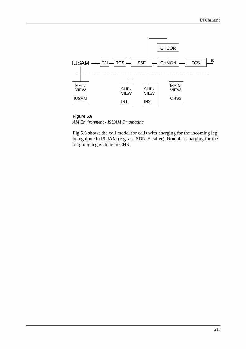
IN Charging
213
Figure 5.6AM Environment - ISUAM Originating
Fig 5.6 shows the call model for calls with charging for the incoming leg being done in ISUAM (e.g. an ISDN-E caller). Note that charging for the outgoing leg is done in CHS.
DJI TCS SSF CHMON TCS
CHOOR
MAINVIEW
IUSAM
SUB-VIEW
IN1
SUB-VIEW
IN2
MAINVIEW
CHS2
BIUSAM

IN 2.3 Service Testing Course
214
5.2 Charging DataFig 5.7 below shows the various data tables associated with charging in an AM - Architecture. Only the tables associated with “call” charging are shown.
Figure 5.7Call Charging Data - AM Architecture
B-NoAnalysis
Traffic ActivityDependantCharging CaseData (CHISP)
Charging CaseData (CIBSP)
Charging ProgData (CIPSP)
ISDN-E ChargingCall BranchingCondition Data(ICBSP)
ISDN-E ChargingCall ChargingProgram Data(ICASP)
Tariff ClassData (CHCSP)
Switching ClassData (CHSSP)
Tariff Data
(CHTSP)
Extended Chrg.Data (CHESP)
CHS (XSS)
IUSAMCHSS (RMP)

IN Charging
215
5.2.1 Call Charging (non-ISDN-E)The data tables for non-ISDN-E call charging is shown in fig 5.8 below:
Figure 5.8Non-ISDN-E Call Charging
The main input into the charging analysis is a Charging Case (CC). Nor-mally CC is specified in B-Number Analysis, but may also be specified from the IN functions. Essentially, the Charging Case depends on the des-tination of the call (e.g. Country and Area codes part of the B-Number).
B-NoAnalysis
Traffic ActivityDependantCharging CaseData (CHISP)
Charging CaseData (CIBSP)
Charging ProgData (CIPSP)
Tariff ClassData (CHCSP)
Switching ClassData (CHSSP)
Tariff Data
(CHTSP)
Extended Chrg.Data (CHESP)
CC
TSCCO,ACO,VPN,etc.CC CHP EAE
TC T
SWC

IN 2.3 Service Testing Course
216
Traffic Activity Dependant Charging Case DataThe Charging Case is first analysed in the table “Traffic Activity Depend-ant Charging Case Data”, which allows branching to a new charging case (NCC).
Branching for “Calls” is based on the TSC (Telecommunications Service Code) and CI (Call Indicator) parameters*. The value of the TSC parame-ter is assigned by “Telecommunications Service Analysis Data” and depends on the bearer capabilities, teleservice, etc. requested by an ISDN call. The value of the TSC code is dependant on the administration.
So, essentially this table allows charging to be dependant on what the call is being used for. Typically, administrations may charge low rates for 3.1 kHz Audio and Speech calls, and higher rates for 56 and 64 kbit/sec calls.
Figure 5.9Traffic Activity Dependant Charging Case Data.
Branching for “calls” can also be done according to the CI (Call Indicator). This indicates the type of call, for example CI-1 indicates ordinary call, CI-2 indicates operator handled call, CI-3 indicates test call, etc.
Both TSC and CI are included as part of the TAC (Traffic Activity Code). See the Application Information for Traffic Activity code for more details.
*Note: Branching is also possible for call event data, this will be discussed in services charging in section 5.2.3
<chisp:cc=31;TRAFFIC ACTIVITY DEPENDENT CHARGING CASE DATAOPERATINGCC BC NCC31 TSC-1 31 TSC-2 31 TSC-5 31 TSC-10 100 TSC-11 100 TSC-14 100 TSC-33 231 TSC-35 231 TSC-40 231END

IN Charging
217
Charging Case DataThe Charging Case (CC) is then analysed in the table “Charging Case Data”, which assigns a Charging Program (CHP). Branching to different charging programs is possible based on a number of parameters:
• VPN-vpn Virtual private network
• PTNCZ-ptncz Private Telecommunication Network (PTN)charging zone
• BGCZ-bgcz Business group charging zone.
• CO-co Origin for charging
• ACO-aco Origin for charging from A-number analysis
• CL-cl Type of A-subscriber
• ACG-acg A-subscriber charging group
• CDC-cdc Call Documentation Class
So essentially, this table allows charging to be dependant on the origin of the call. (e.g. if the caller is a VPN and/or Business Group user, location of calling party, etc.)
Figure 5.10Charging Case Data.
<cibsp:cc=100;CHARGING CASE DATAOPERATINGCC BC CHP100 VPN-0 CO-0 2001 CO-1 1 CO-2 4001 CO-3 4051 CO-4 3001 VPN-1&&-2 PTNCZ-0 2001 PTNCZ-1 CO-0 2100 CO-1 100 PTNCZ-2&-4 101 PTNCZ-3 103 PTNCZ-6 501 END

IN 2.3 Service Testing Course
218
Charging Program DataThe charging program (CHP) is analysed in the table “Charging Program Data” where a number of parameters are assigned to determine how charg-ing will occur for the call.
Figure 5.11Charging Program Data.
The main parameters in Charging Program Data are:
CD The Charging Determination Code.e.g. CD=3 means “own exchange is charging determina-tion point and charging point.”
CP The Charged Party can be:AP: The A-partyBP: The B-partyNP: No Party is charged for the call.
CHM Charge MethodTT: Toll Tickets onlyPM: Pulse Metering onlyTTD: Toll Tickets and Pulse Metering
TC Tariff ClassInput to Tariff Class Data table.
The charging program data can also provide an input to Extended charging analysis and fall back analysis:
EAE Extended Analysis Entry
FBE Fallback Analysis Entry
For more details of these and the other parameters in Charging Program Data refer to the printout description and Traffic Data: Charging Pro-grams.
<cipsp:chp=1; CHARGING PROGRAM DATAOPERATING CHP CD CP TC REG ITI CMA CMAS CS MIS1 EAE MIS3 CHM TC1 ML OTI IS MIS2 PRI FBE 1 3 AP 1 0 1 2 1 TTD 0 0 3
END

IN Charging
219
Extended Charging Analysis DataExtended Charging Analysis provides the ability to over-ride the charging parameters as in the charging program data, based on certain branching conditions.
Figure 5.12Charging Program Data.
The Branching Conditions are:
CHT B-Subscriber Charging Category
NCT Network Conversion Type
Basically the same parameters are available as in charging program data, with some parameters to over-ride items specified in the basic charging program. For example:
NOCHM The Charging Method specified in the basic chargingprogram (i.e. TTD in this case) is cancelled for thisbranch.
For more details of these and the other parameters refer to the printout description and Traffic Data: Extended Charging Analysis.
<chesp:eae=1;EXTENDED CHARGING ANALYSIS DATAOPERATINGEAE/BC CD CP TC REG ITI CMA CSB CHM TC1 ML OTI ISB MIS1 MIS2 MIS3 FBE CMAS 1 CHT-0&-2&&-15 0 0 CHT-1 3 NP 0 0 NOCHM 0 0END

IN 2.3 Service Testing Course
220
Tariff Class and Switching Class DataThe Tariff Class data table essentially points out the tariff to be used. It is possible that the one tariff is always used for the tariff class, but in most cases it is used in association with a switching class to point to a number of different tariffs which will be used at different times.
Figure 5.13Tariff Class and Switching Class Data.
The example above shows a typical Tariff Class and the associated Switching Class. This data specifies which tariff applies on which day, and at which time as follows:
DCAT 0 Normal Weekday00:00 to 08:00 Tariff 2 applies08:00 to 17:00 Tariff 1 applies17:00 to 00:00 Tariff 2 applies
DCAT 1,2, etc. Holidays (e.g. weekends), Public Holidays, etc.All day Tariff 2 applies
We can expect that tariff 1 specifies the tariff for “peak” traffic, whereas tariff 2 specifies the tariff for “off-peak” traffic.
<chcsp:tc=1;TARIFF CLASS DATA OPERATING TC SWC DCAT T 1 1 0 2 1 1 2 3 4 5 6 7 8 9 2END
<chssp:swc=1;SWITCHING CLASS DATA OPERATING SWC DCAT TIME 1 0 0800 1700 1 2 3 4 5 6 7 8 9 END

IN Charging
221
Tariff DataThe Tariff Data specifies the pulses for the particular tariff:
Figure 5.14Tariff Data.
The tariffs 1 and 2 as set for the Tariff Class and Switching Class data is shown in the example above. The parameters shown are:
TDS Time duration in seconds between pulses
NSP Number of start pulses
IDS Initial duration in seconds (between 1st and 2nd pulse)
NPP Number oif periodic pulses
As can be seen in the example, the time durations for each tariff reflect the relative expense of the tariff:
Tariff 1 TDS=180 indicates the “peak” tariffTariff 2 TDS=540 indicates the “off-peak” tariff.
The actual expense of the tariff, of course, depends on how much the net-work operator charges per pulse.
<chtsp:t=1&2;TARIFF DATAOPERATING T TDS NSP IDS NPP 1 180 1 180 1 2 540 1 540 1
END

IN 2.3 Service Testing Course
222
5.2.2 ISDN-E Call Charging DataThe diagram below shows the data tables used for call charging of ISDN-E subscribers*.
Figure 5.15ISDN-E Call Charging Data.
Tariff Class, Switching Class and Tariff Data are implemented in the RMP, and have therefore already been discussed in the previous section.
As mentioned for non-ISDN-E Call Charging, the main input into the charging analysis is a Charging Case (CC). As far as IN is concerned, since ISDN-E charging can only be used for the incoming leg, the CC will always be applied from B-Number analysis. It therefore indicates charging based on the destination (as indicated from parts of the B-number).
*Note: An application dependant parameter specifies whether ISDN-E Charging data or the XSS (non-ISDN-E) charging data is used for ISDN-E subscribers’ calls.
B-NoAnalysis
ISDN-E ChargingCall BranchingCondition Data(ICBSP)
ISDN-E ChargingCall ChargingProgram Data(ICASP)
Tariff ClassData (CHCSP)
Switching ClassData (CHSSP)
Tariff Data
(CHTSP)
CC
TC T
SWCCHP
BSCC,CO,CHT,etc.

IN Charging
223
ISDN-E Charging Call Branching Condition DataThe diagram below shows typical ISDN-E Charging Call Branching Con-dition data:
Figure 5.16ISDN-E Charging Call Branching Condition Data.
This allows the selection of a charging program, for a given CC, based on the where the call originates (e.g. BC=CO-x, etc.) and based on what basic service the call requires (e.g. BC=BSCC-x).
The branching conditions are:
BSCC Basic service charging codeThis is similar to the TSC code in non-ISDN-E charging, and indicates the services required for an ISDN-E call. for example, 3.1 kHz Audio bearer, 64 kbit/sec bearer, teleservice information, etc.Use command IXBCP:BCH=all; to see the BSCC values.
CI Call IndicatorIndicates the type of calle.g. CI-1 means ordinary call, CI-4 means Forwarded call.See application information for Traffic Activity Code.
CO Charging OriginParameter value assigned to a route using EXRBCPROPerty assigned to ISDN-E subscriber using IUSCC
TGR Tariff GroupCPC Calling Party CategoryCHT Called Subscriber Charging Category
PROPerties assigned to ISDN-E subscriber using IUSCC
<icbsp:cc=110;ISDN-E CHARGING CALL BRANCHING CONDITION DATA OPERATING AREA CC BC CHP 110 BSCC-0&&-10 CO-0 1 CO-1 2 CO-2 3 CO-3 4 CO-4 5 BSCC-10&&-16 CO-0 11 CO-1 12 CO-2 13 CO-3 14 CO-4 15END

IN 2.3 Service Testing Course
224
ISDN-E Call Charging Program DataThe diagram below shows typical ISDN-E Call Charging Program Data:
Figure 5.17ISDN-E Charging Call Charging Program Data.
The information in this data table is essentially the same as in the non-ISDN-E Charging Program Data.
CD The Charging Determination Code.e.g. CD=3 means “own exchange is charging determina-tion point and charging point.”
CP The Charged Party can be:AP: The A-partyBP: The B-partyNP: No Party is charged for the call.
TC Tariff ClassInput to Tariff Class Data table.
The Charging Method is defined slightly differently
CHM Charge MethodPM: Pulse Metering onlyPG: Pulse Generation
TT Toll Ticketing Format Entry PointTT=FEP-3 indicates Format Entry Point 3
The charging program data can also provide an input to fall back analysis:
FBE Fallback Analysis Entry
For more details of these and the other parameters in ISDN-E Charging Call Charging Program Data refer to the printout description and Traffic Data: Call Charging Analysis Program ISDN-E.
<icasp:chp=1;ISDN-E CHARGING CALL CHARGING PROGRAM DATA OPERATING AREA CHP CD CP TC TC1 TT IS CMA MLI MIS1 MIS3 CHM TC2 OTI CS CMAS MIS2 FBE 1 3 AP 1 1 PM 1
END
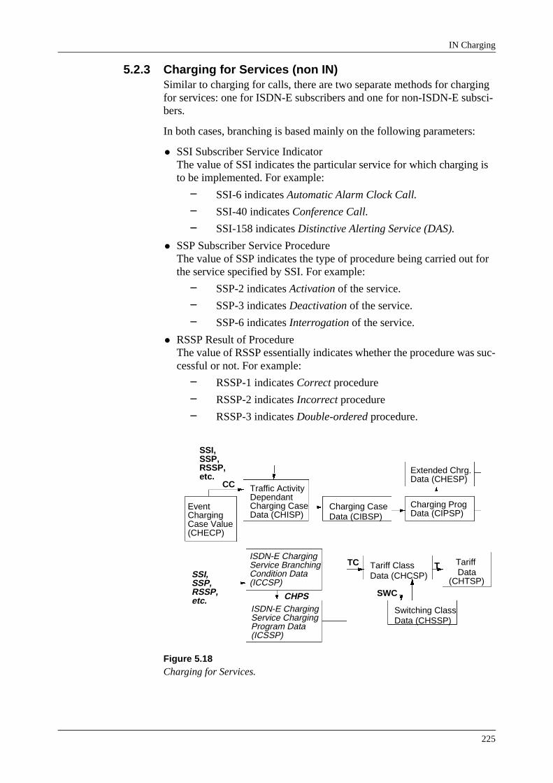
IN Charging
225
5.2.3 Charging for Services (non IN)Similar to charging for calls, there are two separate methods for charging for services: one for ISDN-E subscribers and one for non-ISDN-E subsci-bers.
In both cases, branching is based mainly on the following parameters:
• SSI Subscriber Service IndicatorThe value of SSI indicates the particular service for which charging is to be implemented. For example:
− SSI-6 indicates Automatic Alarm Clock Call.
− SSI-40 indicates Conference Call.
− SSI-158 indicates Distinctive Alerting Service (DAS).
• SSP Subscriber Service ProcedureThe value of SSP indicates the type of procedure being carried out for the service specified by SSI. For example:
− SSP-2 indicates Activation of the service.
− SSP-3 indicates Deactivation of the service.
− SSP-6 indicates Interrogation of the service.
• RSSP Result of ProcedureThe value of RSSP essentially indicates whether the procedure was suc-cessful or not. For example:
− RSSP-1 indicates Correct procedure
− RSSP-2 indicates Incorrect procedure
− RSSP-3 indicates Double-ordered procedure.
Figure 5.18Charging for Services.
ISDN-E ChargingService BranchingCondition Data(ICCSP)
ISDN-E ChargingService ChargingProgram Data(ICSSP)
Tariff ClassData (CHCSP)
Switching ClassData (CHSSP)
Tariff Data
(CHTSP)
TC T
SWCCHPS
SSI,SSP,RSSP,etc.
Traffic ActivityDependantCharging CaseData (CHISP)
Charging CaseData (CIBSP)
Charging ProgData (CIPSP)
Extended Chrg.Data (CHESP)
CC
SSI,SSP,RSSP,etc.
EventChargingCase Value(CHECP)
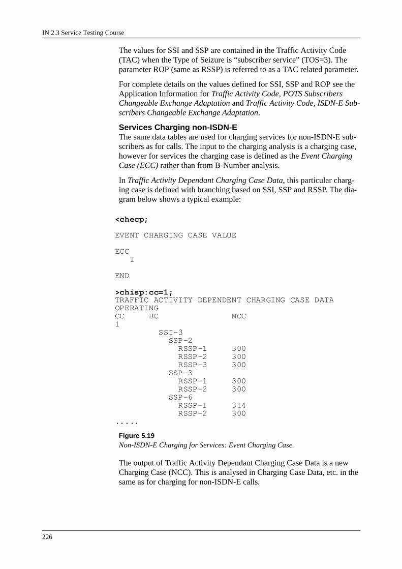
IN 2.3 Service Testing Course
226
The values for SSI and SSP are contained in the Traffic Activity Code (TAC) when the Type of Seizure is “subscriber service” (TOS=3). The parameter ROP (same as RSSP) is referred to as a TAC related parameter.
For complete details on the values defined for SSI, SSP and ROP see the Application Information for Traffic Activity Code, POTS Subscribers Changeable Exchange Adaptation and Traffic Activity Code, ISDN-E Sub-scribers Changeable Exchange Adaptation.
Services Charging non-ISDN-EThe same data tables are used for charging services for non-ISDN-E sub-scribers as for calls. The input to the charging analysis is a charging case, however for services the charging case is defined as the Event Charging Case (ECC) rather than from B-Number analysis.
In Traffic Activity Dependant Charging Case Data, this particular charg-ing case is defined with branching based on SSI, SSP and RSSP. The dia-gram below shows a typical example:
Figure 5.19Non-ISDN-E Charging for Services: Event Charging Case.
The output of Traffic Activity Dependant Charging Case Data is a new Charging Case (NCC). This is analysed in Charging Case Data, etc. in the same as for charging for non-ISDN-E calls.
<checp; EVENT CHARGING CASE VALUE ECC 1 END
>chisp:cc=1;TRAFFIC ACTIVITY DEPENDENT CHARGING CASE DATAOPERATINGCC BC NCC1 SSI-3 SSP-2 RSSP-1 300 RSSP-2 300 RSSP-3 300 SSP-3 RSSP-1 300 RSSP-2 300 SSP-6 RSSP-1 314 RSSP-2 300.....

IN Charging
227
ISDN-E Services ChargingCharging for ISDN-E services is analysed in two data tables:
Figure 5.20ISDN-E Charging Service Branching Condition Data.
The ISDN-E Charging Service Branching Condition Data, provides branching based on SSI, SSP and RSSP and indicates a Charging Program for Services (CHPS).
Figure 5.21ISDN-E Charging Service Charging Program Data.
The ISDN-E Charging Service Program Data specifies the charging pro-gram for the service (CHPS), in a similar way to a charging program for calls (CHP). See ISDN-E Charging Call Charging Program Data.
The output from this table is a tariff class (TC) which is analysed as described for Calls.
<iccsp;ISDN-E CHARGING SERVICE BRANCHING CONDITION DATA OPERATING AREA BC CHPSSSI-3 SSP-2 RSSP-1&&-3 1 SSP-3 RSSP-1&&-3 1 SSP-6 RSSP-1&-2 1 SSP-33 RSSP-1 2 SSP-34 RSSP-1 2 SSP-35 RSSP-1 2 SSP-36 RSSP-1 2 SSP-45 RSSP-1 2
.....
<icssp:chps=all;ISDN-E CHARGING SERVICE CHARGING PROGRAM DATA OPERATING AREA CHPS CP TC TT IS CMA MLI MIS1 MIS3 CHM CS MIS2 1 AP 30 FEP-3 1 1 2 AP 42 FEP-3 1 1END

IN 2.3 Service Testing Course
228
5.2.4 Fallback AnalysesThere are tow fallback analysis tables, for non-ISDN-E charging and ISDN-E charging respectively.
Figure 5.22Fallback Analyses.
The entry point to fall back analysis is specified in:
ISDN-E Charging Call Charging Program Data (for ISDN-E) or
Charging Program Data (for non-ISDN-E)
Branching is based on BSCC (for ISDN-E) or TSC (for non-ISDN-E), which are basically the same.
For ISDN-E Charging:-
<icfsp:fbe=1;ISDN-E CHARGING FALLBACK CHARGING DATA OPERATING AREA FBE BC TC 1 BSCC-11 3
END
For non ISDN-E Charging:-
<cifsp:fbe=1;FALLBACK CHARGING ANALYSIS DATAOPERATINGFBE BC TC 1 TSC-30 3END
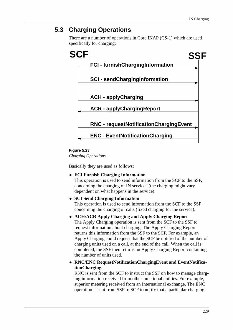
IN Charging
229
5.3 Charging OperationsThere are a number of operations in Core INAP (CS-1) which are used specifically for charging:
Figure 5.23Charging Operations.
Basically they are used as follows:
• FCI Furnish Charging InformationThis operation is used to send information from the SCF to the SSF, concerning the charging of IN services (the charging might vary dependent on what happens in the service).
• SCI Send Charging InformationThis operation is used to send information from the SCF to the SSF concerning the charging of calls (fixed charging for the service).
• ACH/ACR Apply Charging and Apply Charging ReportThe Apply Charging operation is sent from the SCF to the SSF to request information about charging. The Apply Charging Report returns this information from the SSF to the SCF. For example, an Apply Charging could request that the SCF be notified of the number of charging units used on a call, at the end of the call. When the call is completed, the SSF then returns an Apply Charging Report containing the number of units used.
• RNC/ENC RequestNotificationChargingEvent and EventNotifica-tionCharging.RNC is sent from the SCF to instruct the SSF on how to manage charg-ing information received from other functional entities. For example, superior metering received from an International exchange. The ENC operation is sent from SSF to SCF to notify that a particular charging
SCF SSFFCI - furnishChargingInformation
SCI - sendChargingInformation
ACH - applyCharging
ACR - applyChargingReport
RNC - requestNotificationChargingEvent
ENC - EventNotificationCharging

IN 2.3 Service Testing Course
230
event as specified in an RNC, has been received.
5.3.1 Furnish Charging Information (FCI)The purpose of the FCI operation is to send charging information from SCF to SSF, to be stored in the call record. This information being con-cerned with the charging of IN services.
It is possible to send a number of FCI operations during the one call.
Figure 5.24Furnish Charging Information
FCI FunctionsThe FCI operation can specify a number of different items of charging information. It is possible to group these items for descriptive purposes into a number of distinct “functions”. However please note that the one FCI operation could possibly carry out more than one function.
3. Create Billing RecordIt is possible to order the SSF to create an IN Billing record, if a record does not already exist.
4. Add Billing DataData can be specified in an FCI to be added to the call record.For example:Service Feature Codes: These would indicate that a particular feature within a service had been activated.Generic Charging Numbers and Digits: These specify service infor-mation, for use by the off-line billing systems. For example, the number of a Prepaid Calling Card could be stored as a generic charg-ing number.
5. Change TariffBy sending the parameter TariffInformation, the tariff used in the SSP can be changed.
SCP SSP
I.N. ServiceChargingInformation TT File
CallRecord
FCI
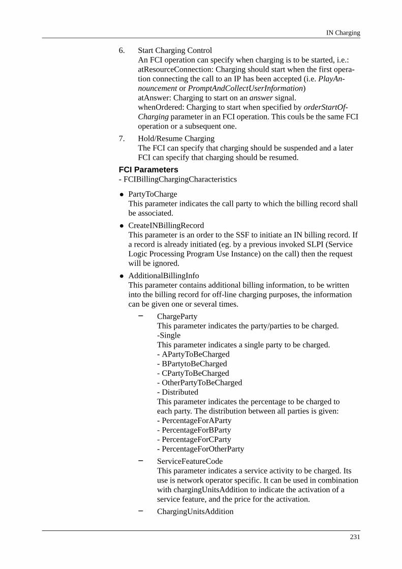
IN Charging
231
6. Start Charging ControlAn FCI operation can specify when charging is to be started, i.e.:atResourceConnection: Charging should start when the first opera-tion connecting the call to an IP has been accepted (i.e. PlayAn-nouncement or PromptAndCollectUserInformation)atAnswer: Charging to start on an answer signal.whenOrdered: Charging to start when specified by orderStartOf-Charging parameter in an FCI operation. This couls be the same FCI operation or a subsequent one.
7. Hold/Resume ChargingThe FCI can specify that charging should be suspended and a later FCI can specify that charging should be resumed.
FCI Parameters- FCIBillingChargingCharacteristics
• PartyToChargeThis parameter indicates the call party to which the billing record shall be associated.
• CreateINBillingRecordThis parameter is an order to the SSF to initiate an IN billing record. If a record is already initiated (eg. by a previous invoked SLPI (Service Logic Processing Program Use Instance) on the call) then the request will be ignored.
• AdditionalBillingInfoThis parameter contains additional billing information, to be written into the billing record for off-line charging purposes, the information can be given one or several times.
− ChargePartyThis parameter indicates the party/parties to be charged.-SingleThis parameter indicates a single party to be charged.- APartyToBeCharged- BPartytoBeCharged- CPartyToBeCharged- OtherPartyToBeCharged- DistributedThis parameter indicates the percentage to be charged toeach party. The distribution between all parties is given:- PercentageForAParty- PercentageForBParty- PercentageForCParty- PercentageForOtherParty
− ServiceFeatureCodeThis parameter indicates a service activity to be charged. Its use is network operator specific. It can be used in combination with chargingUnitsAddition to indicate the activation of a service feature, and the price for the activation.
− ChargingUnitsAddition

IN 2.3 Service Testing Course
232
This parameter indicates a number of units to be added to the charging record.
− GenericChargingDigitsThis parameter indicates a set of generic digits, to be included in the charging record. Makes it possible to provide generic charging information as a digit string for off-line billing pur-poses. The information can be BCD, binary or IA5 coded. The use is operator specific, and is intended for flexible introduc-tion of service or operator specific charging information with-out impact on the on-line charging process.
− GenericChargingNumbersThis parameter indicates a set of generic numbers to be included in the charging record. Makes it possible to provide generic charging information in number format for off-line billing purposes. The use is operator specific, and is intended for flexible introduction of service or operator specific charg-ing information without impact on the on-line charging proc-ess.
• TariffInformationThis parameter contains a tariff to be sent against the charging instance in order to change the charging for the call. The tariff information can only be used to influence the charging in the SSP. The SSP must be pre-pared to accept SCP (IN) charging determination.
− NumberOfStartPulsesIndicates the number of charge units (eg. pulses) that is gener-ated when the tariff is activated.
− StartIntervalIndicates the period after which the first periodic charge unit(s) is generated.
− StartIntervalAccuracyIndicates the unit that the start interval is specified in (0.01 sec. 0.1 sec or 1 sec.).
− NumberOfPeriodicPulsesIndicates the number of charge units (eg. pulses) that is gener-ated after each periodic interval.
− PeriodicIntervalIndicates the duration of the periodic interval.
− PeriodicIntervalAccuracyIndicates the unit that the periodic interval is specified in (0.01 sec. 0.1 sec or 1 sec.).
− ActivationTimeIndicates the time at which the tariff is to be activated.
• StartOfChargingIndicationThis parameter indicates when to start charging. The start of charging indication has only effect in the SSP, ie. it can only indicate when to start charging in the SSP, and it does not cause signalling in the net-

IN Charging
233
work. The following conditions can be specified for when the charging is to be started:
− AtResourceConnectionwhen the first PlayAnnouncement or PromptAndCollectUser-Information operation is accepted.
− AtAnswerwhen answer message is sent or received on the indicated call party connection.
− WhenOrderedwhen the orderStartOfCharging is received from the SCF in a subsequent FurnishChargingInformation operation on the same call party. Charging will not be affected by resource acti-vations, or a sent or received answer message on the indicated call party connection.
• OrderStartOfChargingThis parameter indicates that charging in the SSP related to the indi-cated call party connection must be started immediately.
• ChargingChangeIndicatorThis parameter indicates that the charging in the SSP related to the indi-cated call party connection must be held, or resumed after it has previ-ously been held.
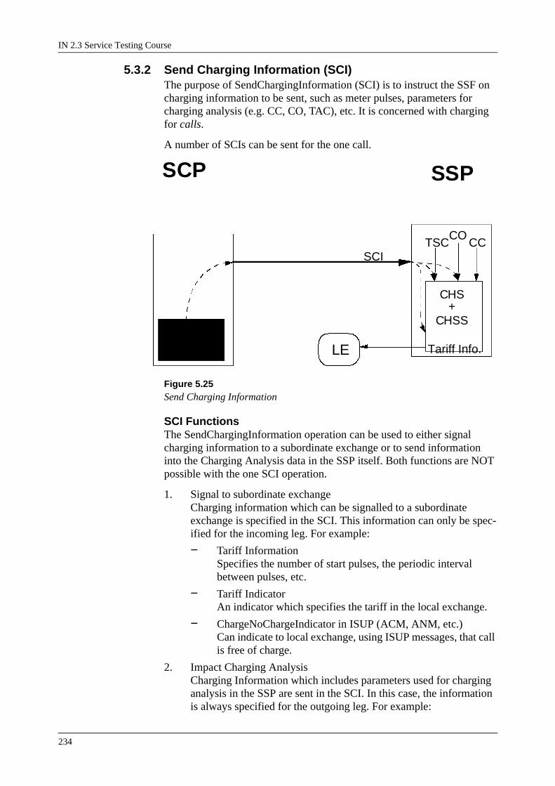
IN 2.3 Service Testing Course
234
5.3.2 Send Charging Information (SCI)The purpose of SendChargingInformation (SCI) is to instruct the SSF on charging information to be sent, such as meter pulses, parameters for charging analysis (e.g. CC, CO, TAC), etc. It is concerned with charging for calls.
A number of SCIs can be sent for the one call.
Figure 5.25Send Charging Information
SCI FunctionsThe SendChargingInformation operation can be used to either signal charging information to a subordinate exchange or to send information into the Charging Analysis data in the SSP itself. Both functions are NOT possible with the one SCI operation.
1. Signal to subordinate exchangeCharging information which can be signalled to a subordinate exchange is specified in the SCI. This information can only be spec-ified for the incoming leg. For example:
− Tariff InformationSpecifies the number of start pulses, the periodic interval between pulses, etc.
− Tariff IndicatorAn indicator which specifies the tariff in the local exchange.
− ChargeNoChargeIndicator in ISUP (ACM, ANM, etc.)Can indicate to local exchange, using ISUP messages, that call is free of charge.
2. Impact Charging AnalysisCharging Information which includes parameters used for charging analysis in the SSP are sent in the SCI. In this case, the information is always specified for the outgoing leg. For example:
SCP SSP
CallChargingInformation
SCI
CHS
CCCO
TSC
CHSS
Tariff Info.LE
+

IN Charging
235
− Charging OriginUsed as parameter CO in Charging Case Data
− Charging CodeThe charging code is mapped to a Charging Case (CC), for analysis in traffic activity dependant charging case data and charging case data.
− Traffic Activity CodeSee Application Information Traffic Activity Code, POTS Sub-scribers Changeable Exchange Adaptation for complete details. The TAC contains parameters TOS (TOS=4 for IN service), TSC, TOI, and TOP.
SCI ParametersSCIBillingChargingCharacteristics
This parameter provides information that is used to influence the billing and/or charging characteristics.
• ChargingInformationThis parameter provides information that is used to influence the billing and/or charging characteristics in the SSF or subordinate exchanges, ie. the information may be signalled backward in the network. The infor-mation is only applicable for call party connections towards the SSF (ie. incoming legs).
− OrderStartOfChargingIndicates that charging is to be initiated immediately for the call party connection towards SSF. SSF will initiate sending of answer backwards in the network to start charging, unless answer has already previously been sent.
− ChargeMessageThis parameter provides charging information to be signalled backward in the network in order to influence the charging in a subordinate exchange.-EventTypeChargingThe following types of charging information can beprovided:-TariffInformation-TariffIndicator-ChargeNoChargeIndicator
-EventSpecificInfoChargingProvides the charging information to be signalled backwardin the network.- TariffInformationContains tariff information to be sent towards a subordi-nate exchange. The tariff information contains informa-tion about the amount of charge units to be generated.- NumberOfStartPulsesIndicates the number of charge units (eg. pulses) that is generated when the tariff is activated.

IN 2.3 Service Testing Course
236
- StartIntervalIndicates the period after which the first periodic charge unit(s) is generated.- StartIntervalAccuracyIndicates the unit that the start interval is specified in(0.01 sec. 0.1 sec or 1 sec.).- NumberOfPeriodicPulsesIndicates the number of charge units (eg. pulses) that is generated after each periodic interval.- PeriodicIntervalIndicates the duration of the periodic interval.- PeriodicIntervalAccuracyIndicates the unit that the periodic interval is spec-fied in (0.01 sec. 0.1 sec or 1 sec.).- ActivationTimeIndicates the time at which the tariff is to be activated.- TariffIndicatorThis parameter contains a tariff indicator to be sent against incoming leg. The content of the parameter can also influence charging instance in subordinate exchanges.- ChargeNoChargeIndicationCorresponds to the ChargeNoChargeIndication in the ISUP BackwardCallIndicators in the messages ACM, ANM, CON and CPG, or similar information in other signalling systems. The interpretation of the indication isnetwork operator specific. The ChargeNoChargeIndica-tion provided by SCF will be used both in messages gen-erated by SSF (eg. ACM and ANM generated to providethrough connection for user interaction) and in messagespropagated through SSF from an outgoing call partyconnection.When ’callFreeOfCharge’ is indicated charging related tothe incoming call party connection in SSF will be can-celled.
− PulseBurstThis parameter specifies the number of pulses to be sent as a pulse burst towards the originating side, the contents of this parameter can influence charging registration in a subordinate exchange.
− CreateDefaultBillingRecordThis parameter indicates that a default charging record must be prepared in an already existing charging instance for the call.
• ChargingAnalysisInputDataThis parameter contains information to be used as input for the charg-ing analysis related to the establishment of an outgoing call party con-nection.
− ChargingOrigin

IN Charging
237
Indicates an entry point in the charging analysis. The entry point can be used to provide different charging for different types of calls (eg. originating or transit) and/or types of sub-scribers.
− ChargingCodeThe chargingCode is an input parameter to the charging analy-sis. The chargingCode normally reflects the destination of the call, ie. for non IN calls the chargingCode is obtained by anal-ysis of the destination address.
− TrafficActivityCodeInput to charging analysis used to indicate the type of traffic activity.
• LegIDThis parameter indicates the call party connection the charging infor-mation refers to.
• ExtensionsThis parameter allows for network operator specific extensions.
− ExtensionFieldThis parameter contains one extension parameter.-TypeThis parameter indicates the type of extension.- CriticalityThis parameter indicates to the receiver how to treat thisextension when unrecognized.- ValueThis parameter contains the value of the extensionparameter.

IN 2.3 Service Testing Course
238
5.3.3 Apply Charging and Apply Charging ReportThe apply charging and apply charging report procedure is used to interact between the SCF and the SSF charging functions. Apply charging is sent from the SCF to request charging information, which is returned by the SSF using Apply Charging Report.
Figure 5.26Apply Charging and Apply Charging Report
ACH and ACR FunctionsThe ACH/ACR procedure requests charging information from the SSF. The sending of the information can be requested in three different ways
1. Report at End of ConnectionInformation can be requested, which will be reported when the Par-tyToCharge (i.e. incoming leg or outgoing leg) is released from the call. The information which can be requested is:
− Accumulated Chargei.e. the number of pulses (charge units) used for the call.
− Actual Tariffi.e. number of start pulses, periodic interval, etc.
− Tariff Changei.e. if the tariff is changed, the new periodic interval, etc.
− Chargeable Durationi.e. duration in tenths of seconds, for which the call was charged.
− Time of AnswerTime stamp indication when an answer signal was received.
2. Report at Charge Limit ReachedA charge limit is specified in the ACH operation, together with the information requested. When this limit is reached, an ACR message returned from SSF with the requested information. If end of connec-tion is detected before the charge limit is reached, the information is returned at this stage. The same information as at “EndOfConnec-tion” can be requested.
3. Report Immediately
SCP SSP
ACH?
ChargingInformationCollected
ACR

IN Charging
239
An ACH can be sent requesting the immediate return of an ACR containing the specified information. Tariff Change information can not be requested in this case, and Time of Answer can only be requested after an answer has already been received.
ACH ParametersAChBillChargCharacteristicsThis parameter specifies the charging related information to be provided by the SSF and the conditions on which this information has to be reported back to the SCF via the ApplyChargingReport operation.
• ReportCondition
− ReportAtEndOfConnectionThis parameter indicates that a report containing the requested information is to be sent to the SCF at the release of the party indicated as party to charge.
− ReportAtChargeLimitThis parameter indicates that a report containing the requested information is to be sent to the SCF when the given threshold value is reached. The total accumulated charge for the call is reported.
− ReportImmediatelyThis parameter indicates that a report containing the requested information is to be sent to the SCF immediately.
• RequestedReportInfoThis parameter specifies a list of specific items of information which is requested by SCF and shall be reported in accordance with the indi-cated report condition. The list may contain:
− AccumulatedCharge This parameter indicates that the accumulated number of charge units (generated and received pulses) is to be reported to the SCF.
− ActualTariffThis parameter indicates that tariff information is to be reported to the SCF. Tariff information will be recorded when ApplyChargingReport operation is reported to the SSF.
− TariffChangeInformationThis parameter indicates that tariff information is to be reported to the SCF. Tariff information will be recorded when-ever a tariff change occurs.
− ChargeableDurationThis parameter indicates that the chargeable duration is to be reported to the SCF.
− TimeOfAnswerThis parameter indicates that the time of answer is to be reported to the SCF.
• SendCalculationToSCPIndicationThis parameter indicates that ApplyChargingReport operations, (at

IN 2.3 Service Testing Course
240
least one) is expected from the SSF. This parameter must always be set to TRUE.
• PartyToChargeThis parameter indicates the party to which the ApplyCharging opera-tion should be applied. When omitted it is interpreted that a report on charging related to the A-party (leg 1) is requested.
• ExtensionsThis parameter allows for network operator specific extensions.
− ExtensionFieldThis parameter contains one extension parameter.- TypeThis parameter indicates the type of extension.- CriticalityThis parameter indicates to the receiver how to treat thisextension when not understood.- ValueThis parameter contains the value of the extensionparameter.
ACR Parameters- CallResultThis mandatory parameter contains the detailed charging information col-lected by the SSF. The contents is network operator specific.
• ReportCondition
− EndOfConnectionThis parameter indicates the end of the connection condition is reached.
− ChargeLimitThis parameter indicates that threshold value condition is reached.
− ImmediatelyThis parameter indicates immediately requested information.
• TimeStampThis parameter contains the time of the day when the report is sent.
• PartyToChargeThis parameter indicates the call party connection (leg) or the party in the call to which the report applies. The contents of this parameter cor-responds to the PartyToCharge parameter provided in the ApplyCharg-ing operation, ie. legId.
• AccumulatedChargeThis parameter contains the number of charge units counted from the beginning of the call or connection until the report is sent. The counter is never reset during a call or a connection. If unavailable, this parame-ter is not reported.
• ActualTariffThis parameter contains the actual tariff information applied to the charged party. If unavailable, this parameter is not reported. Contains

IN Charging
241
parameters as per TariffInformation in SCI. i.e.
− NumberOfStartPulses
− StartInterval
− StartIntervalAccuracy
− NumberOfPeriodicPulses
− PeriodicInterval
− PeriodicIntervalAccuracy
− ActivationTime
• TariffChangeInformationThis parameter contains a list of tariff informations. A tariff informa-tion is applied to the list if tariff change has occured during a call. If unavailable , this parameter is not reported.
− NumberOfStartPulses
− StartInterval
− StartIntervalAccuracy
− NumberOfPeriodicPulses
− PeriodicInterval
− PeriodicIntervalAccuracy
− ActivationTime
• ChargeableDurationThis parameter contains chargeable duration of the call party connec-tion indicated by PartyToCharge. The duration is measured in tenths of seconds. If unavailable, then a value of ZERO is reported for this parameter.
• TimeOfAnswerThis parameter contains a time stamp that indicates the time at which answer was sent or received on the call party connection indicated by PartyToCharge. If unavailable, this parameter is not reported.

IN 2.3 Service Testing Course
242
5.3.4 RequestNotificationChargingEvent & EventNotification-ChargingThe RequestNotificationChargingEvent (RNC) is used to instruct the SSF on how to manage charging events received from other functional entities (FEs). For example, tariff information received from an international exchange. The EventNotificationCharging (ENC) is used to report such events as specified for monitoring in an RNC operation.
Figure 5.27RNC - RequestNotificationChargingEvent & ENC - EventNotificationCharging
RNC FunctionRequestNotificationChargingEvent instructs the SSF how to manage charging events. The charging events which can be monitored are:
• Tariff InformationThe tariff information received from a superior exchange, including number of start pulses, periodic interval, etc.
• Tariff IndicatorA tariff indicator received from a superior exchange.
• ChargeNoChargeIndicator in ISUP (ACM, ANM, etc.)Received as a BackwardCallIndicator to indicate that a call whether a call is to be charged or not.
The RNC will also specify the monitoring mode
Figure 5.28RNC Function - Monitor Modes
• Interrupt ModeEvents received will be notified to SCF, but will not be propogated on
SCP SSP
RNCMonitoring
ENC
MonitorCriteria
SuperiorExchange
LEt
SCF
SSF
SCF
SSF
SCF
SSF
Interrupt NotifyAndContinue Transparent

IN Charging
243
the incoming leg
• NotifyAndContinueEvents received will be notified to SCF and will be propogated on the incoming leg
• TransparetEvents will be propogated on the incoming leg and will not be notified to SCF.
RNC Parameters- ChargingEventIndicates which charging events from superior exchange that the SSP shall monitor for, and the mode in which it shall monitor.
• EventTypeChargingIndicates which of the following charging events that is to be moni-tored:
− TariffInformationIndicates that a tariff received from a superior exchange is to be monitored, according to the MonitorMode.
− TariffIndicatorIndicates that a tariff indicator received from a superior exchange is to be monitored, according to the MonitorMode.
− ChargeNoChargeIndicationIndicates that a received ChargeNoCargeIndication in the BackwardCallIndicator of the ISUP messages ACM, ANM, CON or CPG, or similar information in other signalling sys-tems is to be monitored according to the monitor mode. The interpretation of the ChargeNoChargeIndication is network operator specific.
• MonitorModeIndicates the mode to monitor the charging event in. The applicable modes are ’Interrupted’, ’NotifyAndContinue’ or ’Transparent’.When the mode is ’Interrupted’ or ’NotifyAndContinue’ the occurence of the indicated event will be reported to the SCF. When the mode is ’transparent’ or ’NotifyAndContinue’ the event (eg. the ISUP CRG mes-sage) will be propagated to the incoming leg if applicable (charging events received on legs created with InitiateCallAttempt is never propa-gated). When the mode is ’Interrupted’ the charging event will be dis-carded in the SSP. The ChargeNoChargeIndication will be set to ’No indication’ if monitored in ’Interrupted’ mode.
• LegIdThis parameter indicates the LegId of the call party connection at which the indicated charging event is to be monitored. It is only possible to monitor charging events on call party connections setup from SSF.

IN 2.3 Service Testing Course
244
ENC Parameters
• EventTypeChargingThis parameter contains one of the following charging events.
− TariffInformationIndicates that a tariff has been received from a superior exchange.
− TariffIndicatorIndicates that a tariff indicator has been received from a supe-rior exchange.
− ChargeNochargeIndictorIndicates that a charge or no charge indication has been received from a superior exchange.
• EventSpecificInfoChargingThis parameter contains charging related information specific to the event.
− TariffInformationThis parameter contains a tariff that defines the amount of charge units, that must be generated in a certain case, in which the tariff information is valid.- NumberOfStartPulses- StartInterval- StartIntervalAccuracy-NumberOfPeriodicPulses- PeriodicInterval- PeriodicIntervalAccuracy- ActivationTime
− TariffIndicatorThe tariffIndicator indicates the tariff digits received in a charging message on the call party connection to the terminat-ing party. The interpretation of tariff digits is network operator specific.
− ChargeNoChargeIndicationContains the ChargeNoChargeIndication received as a part of BackwardCallIndicators in the ISUP messages ACM, ANM, CON and CPG, or similar information in other signalling sys-tems. The interpretation is network operator specific.- CallFreeOfChargeIndicates the call is free of charge.- ChargeableCallIndicates the call is chargable.
• LegID
Indicates the party the charging event was received on.
• Extensions
This parameter allows for network operator specific extensions.
− ExtensionField

IN Charging
245
- Type- Criticality- Value
• MonitorModeThis parameter indicates the MonitorMode applicable for the corre-sponding EventTypeCharging subparameter. Monitor may be ’inter-rupted’ or ’notifyAndContinue’.

IN 2.3 Service Testing Course
246
5.4 Charging ControltypesThere are three controltypes in CS1, specifically designed for charging.
Figure 5.29Charging Controltypes
• CHARDAT - Manipulate Charging InformationThe charging of a specified call party can be manipulated by using either:
− Furnish Mode: to add information to a call record or
− Send Mode: to order SSF to send charging information.
• CHARLIM - Check Charging LimitThis controltype supervises the number of charging units used by a call party and compares them to a specified charging limit. There are four modes available:
− Apply Surcharge Mode checks that there are charging units left before the call and then updates the number of units remaining at the end of the connection. An option is available to apply a surcharge.
− Supervise Units Left mode checks that there are charging units left before the call, sets a charging limit and supervises that limt and updates the number of units remaining at the end of the connection (or sets units remaining to 0 if the limit was reached). An surcharge is optional
− Check Units Left mode simply checks the number of units left and selects the appropriate outlet.
− Supervise Units and Offset Mode works similar to the super-vise units left mode, however in this mode an additional offset
Charging Controltypes
Chardat - Manipulate Charging InformationFurnish ModeSend Mode
Charlim - Check Charging Limit apply surcharge modesupervise units left modecheck units left modesupervise units and offset mode
Charrep - Collect Charging InformationApplyChargingRequestNotificationChargingEvent

IN Charging
247
is specified. The SCF is notified both when the reduced limit (i.e. limit minus offset) and the actual limit are reached.
• CHARREP - Collect Charging InformationThis controltype collects charging information of the specified call party. There are two possible argument selections.
− ApplyCharging: This uses the ACH/ACR procedures to report charging information such as accumulated charge, actual tar-iff, chargeable duration, etc. when a specified condition exists (e.g. end of connection).
− RequestNotificationChargingEvent: This uses the RNC/ENC procedures to monitor and report certain charging events, for example the receipt of a “ChargeNoCharge” indicator in an ANM message.

IN 2.3 Service Testing Course
248
5.4.1 CHARDAT - Manipulate Charging InformationThis controltype is used to manipulate charging information by either add-ing information to a call record (using Furnish Mode) or by ordering the SSF to send charging information for input to charging analysis or to be sent to a subordinate exchange (using Send Mode).
The service logic parameters specified for this control type consists of an indication of where to store the error code.
The service data parameters to be specified depend on the mode. The mode is set by service data in the procedure parameter.
Furnish ModeUsed to add information to a call record, in order to specify charging for IN services. This is done by invoking the FurnishChargingInformation (FCI) operation.
Figure 5.30CHARDAT - Furnish Mode
For Furnish Mode, the service data contains:
• Service Data for both modes (at Data Module Level):
− Call Party (Leg ID)Specifies the Call party to Charge (i.e. the leg id)
− Procedure (Arg. Sel. - Argument Selection)Specifes FurnishChargingInformation in this instance
− Dialogue Type (Dialogue)Indicates initiating or assisting.
• Service Data for Furnish Mode (at Row Level for FCI Arguments)
− Create IN Billing RecordTo create a call record if one does not already exist.
− Additional Billing Info
Where to store error codeService Logic Parameters
continue
error
Call Party
Additional Billing InfoTariff InformationStart of ChargingCharging Change Indicator
Create IN Billing Record
Procedure = FCIDialogue Type
FCI
Service Data

IN Charging
249
Information to be added to the call record
− Tariff InformationTo change the tariff by specifying periodic interval, start pulses, etc.
− Start of ChargingSpecifies when charging should start.
− Order to Start ChargingUsed if Start of Charging = whenOrdered.
− Charging Change IndicatorUsed to hold/resume charging.
You will notice that the specific Service Data for furnish mode, simply maps to the parameters provided for in a FurnishChargingInformation operation as described in the previous section on Charging Operations.
If the FCI procedure is successfully invoked outlet 0 of the CHARDAT controltype is selected
If an error occurs (i.e. the FCI procedure is not started), outlet 1 is selected.

IN 2.3 Service Testing Course
250
Send ModeUsed to order the SSF to send charging information either to Charging Analysis or a subordinate exchange in order to influence charging for calls. This is done by invoking the SendChargingInformation (SCI) opera-tion.
Figure 5.31CHARDAT - Send Mode
For Send Mode, the service data contains:
• Service Data for both modes (at Data Module level):
− Call Party (Leg ID)Specifies the Call party to Charge (i.e. the leg id)
− Procedure (Arg. Sel. - Argument Selection)Specifes SendChargingInformation in this instance
− Dialogue Type (Dialogue)Indicates initiating or assisting.
• Service Data for Send Mode (at Row level for SCI arguments)
− Order start of ChargingTo order start of charging if not already done so, by propogat-ing an answer signal to the network.
− Charge MessageCan contain Tariff information (i.e. periodic interval, etc.), a tariff indicator and/or ChargeNoChargeIndication
− Pulse BurstSpecifies a number of pulses to be sent in a pulse burst to a subordinate exchange.
− Create Default Billing RecordTo indicate that a default billing record must be prepared.
− Charging Analysis Input Datai.e. Charging Origin, Charging Code and/or Traffic Activity
Where to store error codeService Logic Parameters
continue
error
Call Party
Charge MessagePulse BurstCreate Default Billing RecordCharging Analysis Input Data
Order Start of Charging
Procedure = SCIDialogue Type
SCI
Service Data

IN Charging
251
Code can be sent as inputs to charging analysis.
You will notice that the specific Service Data for send mode, simply maps to the parameters provided for in a SendChargingInformation operation as described in the previous section on Charging Operations.
If the SCI procedure is successfully invoked outlet 0 of the CHARDAT controltype is selected
If an error occurs (i.e. the SCI procedure is not started), outlet 1 is selected.
Applications for CHARDATTypical applications for the CHARDAT controltype would be:
• FreephoneBy using furnish mode we could specify the charged party to specify that:
− Free of charge for A-party
− Charged to B-party’s account
• Information ServicesBy using furnish mode with the startOfChargingIndicator set to whenOrdered and a new tariff specified. This tariff can then be turned on when appropriate to ensure that:
− Charge depends on type of information
− Low tariff for "menus"
− High tariff for "information"
• Split Charging ServiceBy using furnish mode, with startOfChargingIndicator set for atAnswer and by specifying the percentage of charging to be paid by each of the parties (i.e. A-party, B-party, C-party and Other-party), it is possible to specify that:
− Charges distributed between the parties
• Free Call ServiceBy using send mode, with chargingInformation set to callFreeOf-Charge and the charging event to ChargeNoChargeIndication, it is possible to specify that:
− Nobody pays for the call
Generic Charging Digits and NumbersGeneric Charging Digits and Numbers can be defined as “User Call Data” or “Call Related Event Data”
• User Call Data (UCD)The value is stored in the call record with the appropriate Tag-id.
• Call Related Event Data (CRED)TAC is assigned (TOS, TOP, TOI, TSC) so that the event can be charged.
See Application Parameters for block SSFCHM.

IN 2.3 Service Testing Course
252
5.4.2 CHARLIM - Check Charging LimitThe CHARLIM controltype provides the possibility to control a call depending on the number of charging units used.
Figure 5.32CHARLIM - Check Charging Limit.
The Service Logic Parameters (IR parameters) set for CHARLIM are:
• ModeSee next section “CHARLIM Modes & Subfunctions”
• Call Party (Leg ID)
• Priority
• KoV to store charging units left
• KoV to load limit almost reached offset
• KoV to load limit in units per call
• KoV to load number of units left
• KoV to load additional charge units
The Service Data (MIS parameters)contains
• Number of units left
• Limit in units per call
• Reset period in days
• Reset value
• Surcharge units
• Offset Value
• Dialogue Type0: Initiating1: Assisting
Mode
Where to read Limit offsetWhere to read limit per callWhere to read units left
Where to store Units Left
Call PartyPriority
Where to read surcharge
Service Logic ParametersCharging Units Left
Reset periodReset ValueDialogue Type
Surcharge
Charging Limit OffsetCharging Limit per Call
Service Data
ResultDependson Mode

IN Charging
253
CHARLIM Modes and SubfunctionsThe CHARLIM can carry out a selection of 5 different subfunctions, the particular subfunctions carried out depend on the mode set for the particu-lar logic module. Briefly the 5 subfunctions are:
1. Check on charging units remainingChecks that >0 charging units are left, if 0 units left appropriate out-let selected.
2. Determine the number of charging units available for the call.The number of units available is the lesser of the “charging limit per call” and “charging units remaining”.
3. Check if Charging Units available are usedSupervises the number of units used during a call using the ACH/ACR procedures. An “offset” may be specified, which results in two charging limits - the actual limit and a reduced limit (i.e. actual limit minus offset).
4. Update Charging Units remainingThe number of units used during the call is subtracted from the orig-inal units available and stored as the number of units remaining.
5. Apply a surchargeAn optional surcharge can be applied for the call. This is sent using the FCI procedure.
The particular subfunctions executed for each mode are shown in the table below:
Where:
Subfuntion 3a refers to supervision of a charging limit without offset and 3b refers to supervision of a charging limit with offset.
Subfunction 5 (apply a surcharge) is optional in all applicable modes.
Subfunction
Mode 1 2 3a 3b 4 5
0: Send additional charging units(“Apply surcharge”)
➼ ➼ ➼ ➼
1: Send real charge limit and addi-tional charging units(“Supervise units used”)
➼ ➼ ➼ ➼ ➼
2: Perform only SCF check on charging units left(“Check units left”)
➼
3: Send Advise, real charging limit and additional charging units(“Supervise units and offset”)
➼ ➼ ➼ ➼ ➼

IN 2.3 Service Testing Course
254
Mode 0: “Apply Surcharge”The diagram below shows the operation of a CHARLIM in mode 0
Figure 5.33CHARLIM - Apply Surcharge Mode.
In this mode the following actions are performed:
1. The SCF prepares the data for the request to Check Charging Limit.
2. The SCF invokes procedure ApplyCharging (ACH) with the request for report at end of connection.
3. If a surcharge is specified the procedure FurnishChargingInforma-tion (FCI) is invoked.
4. At the end of the connection the SSF sends the Apply Charging Report with the number of used charging units to the SCF.
5. The charging units left are updated. If the number of used charging units exceeds the number of charging units left the value 0 is stored as number of charging units left.
The outlet selected will be:
Outlet 0: Continue or Success. ACH (and FCI if surcharge) successfully invoked
Outlet 1: Insufficient charging units available
Mode = "Apply surcharge".....
Service Logic Parameters
success
not enough units
ACH(FCI)
ACR
1. Check Units2. ACH - report at end of conn.3. FCI (if surcharge)4. ACR received5. Update units left
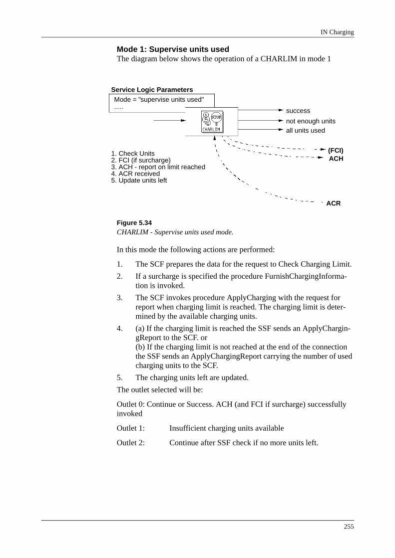
IN Charging
255
Mode 1: Supervise units usedThe diagram below shows the operation of a CHARLIM in mode 1
Figure 5.34CHARLIM - Supervise units used mode.
In this mode the following actions are performed:
1. The SCF prepares the data for the request to Check Charging Limit.
2. If a surcharge is specified the procedure FurnishChargingInforma-tion is invoked.
3. The SCF invokes procedure ApplyCharging with the request for report when charging limit is reached. The charging limit is deter-mined by the available charging units.
4. (a) If the charging limit is reached the SSF sends an ApplyChargin-gReport to the SCF. or(b) If the charging limit is not reached at the end of the connection the SSF sends an ApplyChargingReport carrying the number of used charging units to the SCF.
5. The charging units left are updated.
The outlet selected will be:
Outlet 0: Continue or Success. ACH (and FCI if surcharge) successfully invoked
Outlet 1: Insufficient charging units available
Outlet 2: Continue after SSF check if no more units left.
Mode = "supervise units used".....
Service Logic Parameters
success
not enough units
ACH(FCI)
ACR
all units used
1. Check Units2. FCI (if surcharge)3. ACH - report on limit reached4. ACR received5. Update units left

IN 2.3 Service Testing Course
256
Mode 2: Check Units LeftThe diagram below shows the operation of a CHARLIM in mode 2
Figure 5.35CHARLIM - Check Units Left Mode.
In this mode the following actions are performed:
1. The check of charging units left is an SCF-internal action.
The outlet selected will be:
Outlet 0: Success: Charging units left
Outlet 1: Insufficient charging units available
Mode 3: Supervise Units and OffsetThe diagram below shows the operation of a CHARLIM in mode 3
Figure 5.36CHARLIM - Supervise Units + Offset Mode.
In this mode the following actions are performed:
1. The SCF prepares the data for the request to Check Charging Limit
Mode = "check units left".....
Service Logic Parameters
success
not enough units
1. Check Units
Mode = "supervise units + offset".....
Service Logic Parameters
successnot enough units
ACH(FCI)
ACR
all units used
1. Check Units2. FCI (if surcharge)3. ACH - report on limit with offset4. ACR received5. ACH - report on limit
ACH
ACR
6. ACR received7. Update units left
only offset left

IN Charging
257
with offset.
2. If a surcharge is specified the procedure FurnishChargingInforma-tion is invoked.
3. The SCF invokes procedure ApplyCharging with the request for report when the charging limit is reached. The charging limit is determined by the available charging units reduced by the offset.
4. When only the offset charging units are left the SSF sends an Apply-ChargingReport to the SCF.
5. The SCF invokes procedure ApplyCharging with the request for report when charging limit is reached. Now the charging limit is determined by the totally available charging units.
6. If the charging limit is reached the SSF sends an ApplyChargingRe-port to the SCF.If the call is disconnected before either charging limit is reached (as apecified in actions 3 and 5) the SSF sends an ApplyChargingReport carrying the number of used charging units to the SCF.
7. The charging units left are updated.
The outlet selected will be:
Outlet 0: Continue or Success. ACH (and FCI if surcharge) successfully invoked
Outlet 1: Insufficient charging units available
Outlet 2: Continue after SSF check if no more units left.
Outlet 3: Continue after SSF check with Advise-charge limit.
CHARLIM ApplicationsTypical applications for the CHARLIM controltype include:
• Calling Card ServicesA number of services are used such as account card calling, prepaid calling cards, credit card calling, etc.
− Keep track of units used.Allows announcement of units available on this account.
− Supervises limits - units available and/or limit per call.Prepaid Cards limited on total amount per card.Limit per call is a common feature of credit and account card services
− Offset - account is nearly empty, play announcement.Allows an announcement before the actual limit is reached to inform the user that the call will be terminated shortly.
• Other Services
− Any services/features depending on the number of used units.

IN 2.3 Service Testing Course
258
5.4.3 CHARREP - Collect Charging InformationThis controltype allow charging information to be requested. It also allows the possibility to control the call depending on this information.
There are two distinct modes, specified by the Argument Selection param-eter.
Arg. Sel. = 0: ApplyCharging (default)
Arg. Sel. =1: RequestNotificationChargingEvent
CHARREP - ApplyChargingThe diagram below describes the operation of a CHARREP with the ApplyCharging arguments selected:
Figure 5.37CHARREP - ApplyCharging arguments selected.
In this mode the following parameters are applied:
• Service Logic Parameters
− Mode=0 (Dummy)
− Priority
• Service Data Parameters at Data Module Level
− Arg. Sel. = 0 for ApplyCharging
− LegID (Call Party)
− Rep./CharSince ApplyCharging is selected this specifies requested report conditions (i.e. Rep.):1 = Report at end of connection3 = Report immediately
− Dial./Mon.Since ApplyCharging is selected this specifies dialogue type
PriorityService Logic Parameters
Arg-Sel=ApplyCharging
Send calculation to SCP Ind.Call Party
Requested Report Info.
Dialogue TypeRequested Report Cond.
Service Data
continue
end of connection
immediately
ACH
ACR
1. Prepare Data2. Send ACH3. ACR received

IN Charging
259
(i.e. Dial.)
• Service Data Parameters at Row level:
− Specifies parameters as per ACH operation(refer to Charging Operations section)
In this mode the following actions are executed:
1. The SCF sends a request to Apply Charging to the SSF and outlet 0: "continue" is selected.
2. When the SCF receives a Apply Charging Report with report condi-tion end of connection from the SSF. Outlet 1 "end of connection" is selected. The report information is stored in event data.
3. When the SCF receives a Apply Charging Report with report condi-tion immediately from the SSF and Outlet 3 "immediately" is selected. The report information is stored in event data.
Note: Outlet 2 is not used in this mode.
CHARREP - RequestNotificationChargingEventThe diagram below describes the operation of a CHARREP with the RequestNotificationChargingEvent arguments selected:
Figure 5.38CHARREP - RequestNotificationChargingEvent arguments selected.
In this mode the following parameters are applied:
• Service Logic Parameters
− Mode=0 (Dummy)
− Priority
− Discard Monitor Indicator
• Service Data Parameters at Data Module Level
− Arg. Sel. = 1 for RequestNotificationChargingEvent
− LegID (Call Party)
− Rep./Char
PriorityService Logic Parameters
Arg-Sel=RequestNotification.
Call Party
Event type chargingMonitor Mode
Service Data
continuetariff information
charge/no charge
RNC
ENC
1. Prepare Data2. Send RNC3. ENC received
tariff indicator
Discard Monitor Indicator

IN 2.3 Service Testing Course
260
Since RequestNottificationChargingEvent is selected this specifies requested charging events (i.e. Char.):1Tariff Information2Tariff Indication3Tariff information and indication4ChargeNoCharge indication5Tariff information and ChargeNoCharge indication6Tariff indication and ChargeNoCharge indication7Tariff information, Tariff indication and ChargeNoCharge indication
− Dial./Mon.Since RequestNotificationChargingEvent is selected this spec-ifies Monitor mode (i.e. Mon.)0Interrupted1Notify and Continue
• Service Data Parameters at Row level:
− Specifies parameters as per RNC operation(refer to Charging Operations section)
CHARREP Applications
• Advice On Charge FeatureAdvice on Charge is a feature which informs the user of charging infor-mation. Thus CHARREP could be used to determine charging informa-tion concerning the call (using ACH argument selection). This information could then be passed on to the user with a USERINT con-troltype.
− CHARREP to determine charging info.
− Userint to inform user
• Superior TariffingCHARREP using RCH argument selection, determines how charging information received into SSF from other functional entities are han-dled.
− Tariff information can be requested from an international exchange, for example.

IN Charging
261
5.5 Commands Affecting ChargingThere are three commands, used when setting up the SSF data, that have an influence on charging.
5.5.1 SWIDI - Service Switching IN Service Trigger DataThe following groups of parameters affect charging:
• CCCan specify a default Charging Case to be used for the outgoing leg
• TAC (TOI, TOS, TOP, TSC)The parts of the Traffic Activity Code (TOI, TOS, TOP, TSC) can be specified to be used as an input to the charging analysis for the outgoing leg (i.e. as branching in traffic activity dependant charging case data)
• Indicators: CHINIC, FWINDIC, MPINDICCHINDIC: Sets default setting for ChargeNoCharge indicator in ISUP ANM message.FWINDIC: Specifies if outgoing leg looks like a forwarded callMPINDIC: Indicates whether meter pulses received on outgoing leg should be transferred to incoming leg or not.
• Transfer I/C > O/G: CHZTR, COTR, TACTRSpecifies if parameters received on incoming leg should be transferred to outgoing leg:CHZTR: Whether BGCZ and PTNCZ should be transferred or not.COTR: Whether CO should be transferred or not.TACTR: Whether TAC (TSC, TOI, TOS, TOP) should be transferred.(BGCZ, PTNCZ and CO are used for branching in Charging Case Data,TSC, TOI, TOS, TOP are used for branching in Traffic Activity Dependant Charging Case Data)
• Transfer O/G > I/C: TAFINFOSpecifies if Tariff Information and Tariff Indicators received on outgo-ing leg should be transferred to the incoming leg.

IN 2.3 Service Testing Course
262
The values of these parameters on an existing IST can be printed using SWISP
Figure 5.39SWISP Command.
5.5.2 SWSEC - Service Switching Exchange Data ChangeThe following parameters affect charging:
• CCSets a default Charging Case to be transferred to the outgoing side.
• TAC (TOI, TOS, TOP, TSC)Sets default values for TOI, TOS, TOP, TSC to be transferred to the outgoing side.
The current settings for Service Switching Exchange Data can be printed using SWSEP:
Figure 5.40SWSEP Command.
<swisp:ist=1;SSF IN SERVICE TRIGGER DATA DATA PRINTED FROM THE OPERATING AREA IST1 ACAT BSI TOI TOTR TACTR CHINDIC SSC10 0 0 0 0 0 0 BOTR CC TOP SHREQ TAFINFO FWINDIC PSCF0 NO 0 0 0 1 NO COTR RI TOS OBCAT CPAI SSFTYPE PCID0 1 0 7 0 0 NO ROTR SEC TSC CHZTR IMPAIND MPINDIC TSUS0 0 0 0 1 0 60 TDP ROUTING2 DATA..........
<swsep;SSF EXCHANGE DATA LOC3BIT NUMBER IN IPSSPCAPNO OBCAT ACAT IMPAIND CC TOI TOS TOP TSCETC 7 0 1ICA 7 0 1 NO 0 0 0 0CON 7 0 1 NO 0 0 0 0 END
IN Charging
263
5.5.3 EXRBC Exchange Data Specification for Route Data ChangeThe following parameter affects charging:
• CO - Charge Origin
Thus by specifying this parameter on the appropriate “incoming” SSFDCF routes (i.e. FNC=1, 2, 3 or 5), a default CO (Charge Origin) can be speci-fied for the outgoing leg.
5.5.4 InterferenceAs we have seen, parameters used for charging analyses can be provided from SCF (using INAP operations), from SSF per IST, Transferred from the incoming side or from SSF per exchange.
In general the following rules apply:
• Parameters received from SCF overrule all other values for the parame-ter (e.g. chargingOrigin in SCI operation)
• If SWISP indicates that a parameter can be transferred from the incom-ing side to the outgoing side, this will over rule the default values. The default values will be used in these instances only when the information id not available from the incoming side.
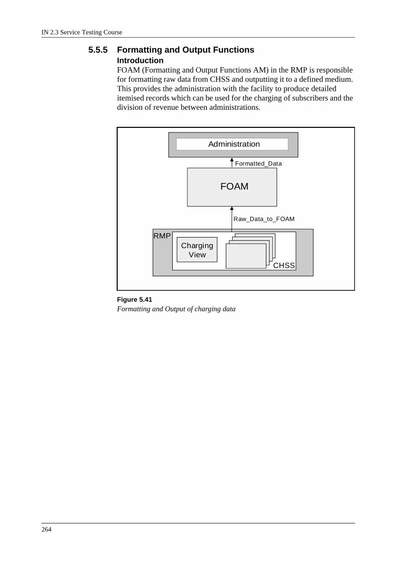
IN 2.3 Service Testing Course
264
5.5.5 Formatting and Output FunctionsIntroductionFOAM (Formatting and Output Functions AM) in the RMP is responsible for formatting raw data from CHSS and outputting it to a defined medium. This provides the administration with the facility to produce detailed itemised records which can be used for the charging of subscribers and the division of revenue between administrations.
Figure 5.41Formatting and Output of charging data
RMP
CHSS
ChargingView
Administration
FOAM
Formatted_Data
Raw_Data_to_FOAM

IN Charging
265
FOAM ArchitectureThe diagram below illustrates the internal structure and the location of each block within FOAM.
Figure 5.42FOAM Architecture
The blocks in FOAM may be categorised as handling one of the following functional areas:
Data Collection
The Protocol Adaptor (PA) block provides the interface between CHSS in the RMP and FOAM.
Formatting and Output
The blocks Charging Check Output (CHACO), Immediate Service (IS) and most of the blocks of the Common Charging Output (CCO) Complex are responsible for the formatting and output of data to a prede-fined output medium
AdministrationThere following data tables are used for common charging output:
• Common Charging Output Limit Data (CHOLP)
• Common Charging Output User Function Data (CHOTP)
• Common Charging Output Congestion Data (CHOCP)
• Common Charging Output Record Output Data (CHROP)
• Common Charging Output File Attribute Data (CHOTP)
• Common Charging Output File Status Data (CHOFP)
FOAMCHOD
ISC
IS CHACO
PA
RMP
CCO Complex
CHOFCAS
CHOFTT
CHOFICI
CHOFCS
CHOC
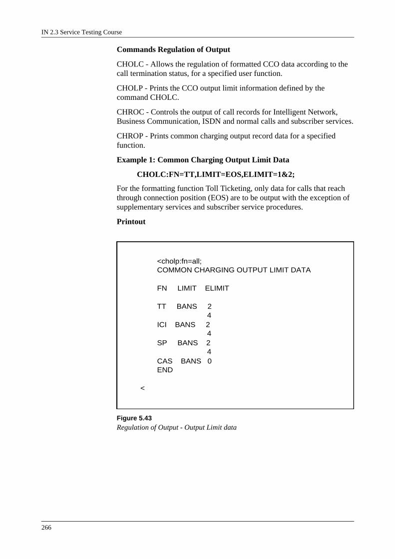
IN 2.3 Service Testing Course
266
Commands Regulation of Output
CHOLC - Allows the regulation of formatted CCO data according to the call termination status, for a specified user function.
CHOLP - Prints the CCO output limit information defined by the command CHOLC.
CHROC - Controls the output of call records for Intelligent Network, Business Communication, ISDN and normal calls and subscriber services.
CHROP - Prints common charging output record data for a specified function.
Example 1: Common Charging Output Limit Data
CHOLC:FN=TT,LIMIT=EOS,ELIMIT=1&2;
For the formatting function Toll Ticketing, only data for calls that reach through connection position (EOS) are to be output with the exception of supplementary services and subscriber service procedures.
Printout
Figure 5.43Regulation of Output - Output Limit data
<cholp:fn=all; COMMON CHARGING OUTPUT LIMIT DATA FN LIMIT ELIMIT TT BANS 2 4 ICI BANS 2 4 SP BANS 2 4 CAS BANS 0 END <

IN Charging
267
Example 2: Common Charging Output Record Data
CHROC:FN=ICI,CALL=OFF,INCALL=OFF,BCCA-LL=OFF,ISDNCALL=ON,SUS=OFF;
Only ISDN calls will be output for the output function Immediate Call Itemisation.
Printout
Figure 5.44Regulation of Output - Record Output Data
<chrop:fn=all; COMMON CHARGING OUTPUT RECORD OUTPUT DATA FN CALL INCALL BCCALL ISDNCALL SUS TT ON ON ON ON ON ICI ON ON ON ON ON SP ON ON ON ON ON CAS ON ON ON ON ON END <

IN 2.3 Service Testing Course
268
Commands Output Congestion
Congestion may occur in the output of formatted data.
CHOCC - Is used to specify and change the predefined/full congestion parameters.
CHOCP - Prints the values of the congestion parameters.
Example 3: Common Charging Output Congestion Data
CHOCC:FN=TT,PL=13,PLE=12;
The number of individuals for Toll Ticketing set to a predefined limit for congestion 13%, the end limit is set to 12%.
Printout
Figure 5.45Common Charging Output Congestion Data
<chocp:fn=all; COMMON CHARGING OUTPUT CONGESTION DATA FN PL PLE AF AEF TT 100 100 1 1 ICI 100 100 1 1 SP 100 100 1 1 CAS 100 100 1 1 END <
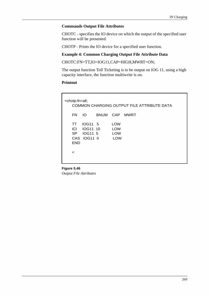
IN Charging
269
Commands Output File Attributes
CHOTC - specifies the IO device on which the output of the specified user function will be presented.
CHOTP - Prints the IO device for a specified user function.
Example 4: Common Charging Output File Attribute Data
CHOTC:FN=TT,IO=IOG11,CAP=HIGH,MWRT=ON;
The output function Toll Ticketing is to be output on IOG 11, using a high capacity interface, the function multiwrite is on.
Printout
Figure 5.46Output File Attributes
<chotp:fn=all; COMMON CHARGING OUTPUT FILE ATTRIBUTE DATA FN IO BNUM CAP MWRT TT IOG11 5 LOW ICI IOG11 10 LOW SP IOG11 5 LOW CAS IOG11 0 LOW END <
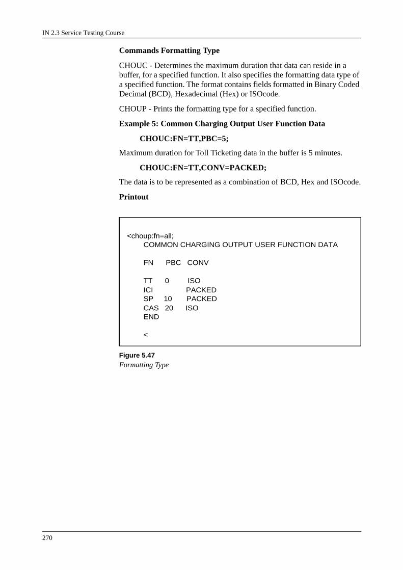
IN 2.3 Service Testing Course
270
Commands Formatting Type
CHOUC - Determines the maximum duration that data can reside in a buffer, for a specified function. It also specifies the formatting data type of a specified function. The format contains fields formatted in Binary Coded Decimal (BCD), Hexadecimal (Hex) or ISOcode.
CHOUP - Prints the formatting type for a specified function.
Example 5: Common Charging Output User Function Data
CHOUC:FN=TT,PBC=5;
Maximum duration for Toll Ticketing data in the buffer is 5 minutes.
CHOUC:FN=TT,CONV=PACKED;
The data is to be represented as a combination of BCD, Hex and ISOcode.
Printout
Figure 5.47Formatting Type
<choup:fn=all; COMMON CHARGING OUTPUT USER FUNCTION DATA FN PBC CONV TT 0 ISO ICI PACKED SP 10 PACKED CAS 20 ISO END <
IN Charging
271
5.6 Module Summary• Charging is a key function for network operators as it is the means by
which they translate network traffic into revenue. Therefore, it is essen-tial that accurate and detailed charging data is available for billing and statistical purposes.
• These Charging functions are performed by different components, Sys-tem Modules, of the AXE 106 architecture.For example IUSAM and XSS perform Charging Analysis, for ISDN-E and non ISDN-E respectively. Outgoing IN Charging Analysis is always per-formed in XSS.The RMP performs Charging Generation and Charging Statistics and FOAM performs the majority of Charging Output.
• There are six operations in Core INAP (CS-1) used specifically for charging.FCI - Furnish Charging Information, SCF to SSF.Sends information for the charging of IN services.
SCI - Send Charging Information, SCF to SSF.Sends information for the charging of IN calls.
ACH - Apply CHarging, SCF to SSF.Requests charging information, such as units used, from SSF. It can also specify a “charge limit”.ACR - Apply Charging Report, SSF to SCF.Returns the charging information requested in an ACH operation.
RNC - Request Notification Charging Event, SCF to SSF.Specifies how charging events received by other FEs should be handled by SSF.ENC - Event Notification Charging, SSF to SCF.Reports charging events as specified by RNC operation.
• There are three controltypes in AXE IN2.2 specifically related to charg-ing.CHARDAT - Is used to send charging information to SSF, using fur-nish-mode (FCI) for charging of services or send-mode (SCI) for charg-ing of calls.CHARLIM - Is used to control a call depending on the number of units used. The ACH/ACR procedures are used to specify charge limits and to report on the number of units used.CHARREP - Used to collect charging information. The argument selection specifies whether ACH/ACR procedures are used to report tariffs, number of units used, etc. or RNC/ENC procedures are used to monitor and report charging events from other FE’s, such as ChargeNo-Charge indications.
IN 2.3 Service Testing Course
272
• There are three commands related to SSF, which can affect charging:SWIDI - SSF IN Service Trigger DataSWSEC - SSF Exchange DataEXRBC - Exchange Data Specification for Route Data (when applied to SSFDCF routes).
• FOAM - Formatting and Output Application Module is responsible for the output of charging information. The following data tables are applied:CCO Limit Data (CHOLP)CCO User Function Data (CHOUP)CCO Output Congestion Data (CHOCP)CCO Record Output Data (CHROP)CCO File Attribute Data (CHOTP)CCO File Status Data (CHOFP)
• When testing IN services, charging should be verified.Pulse metering should be verified by printing call meter values before and after the test case using CHSIP.
Toll Tickets should be verified by creating a new subfile for each test case using IOIFE. The contents of the subfile can be viewed using the IOFAT command.The Toll Ticket contains fixed fields and Tagged Data. Tagged Data for IN calls, can be determined by translating the tag-id to a Charging Data ID which can be found in the application information for block SSFCHM.Application Parameter CRECPERBUFF can be set to zero to ensure immediate output of Toll-tickets, in a test exchange.
Related Documents