BRAKE SYSTEM 1988 Toyota Celica 1988-89 BRAKES Toyota Celica, Corolla, MR2, Tercel DESCRIPTION The hydraulic brake system uses a tandem master cylinder with a vacuum power assist servo. MR2 and some Celica models are equipped with 4-wheel disc brakes. Corolla and Corolla FX are available with either rear drum or rear disc brakes. Tercel models are equipped with front disc and rear drum brakes. A load sensing proportioning valve is used on some models to regulate brake pressure between the front and rear circuits. The rear brakes on all models are self-adjusting. The parking brake lever mechanically activates the rear brakes. On models with rear drum brakes, a cable applies the rear shoes. On MR2, Corolla and Corolla FX models with rear disc brakes, the parking brake applies the rear pads. On Celica models, the parking brake is a duo servo mechanical drum brake design built into the bell of rear rotor assemblies. DRUM BRAKES ADJUSTMENTS NOTE: All rear drum brakes have a self-adjuster which is activated when brake pedal is applied as vehicle travels in reverse. To manually adjust rear brakes, raise and support vehicle. Remove plug from adjustment hole in backing plate. Turn adjusting nut until shoes lock wheel. Back adjuster off until wheel turns freely or with very slight drag. Measured clearance between linings and braking surface of drum should be .024" (.60 mm). BRAKE PEDAL HEIGHT ADJUSTMENTS 1) Brake pedal height is measured from face of pedal pad to asphalt sheet under carpet. To adjust clearance, loosen stoplight switch and lock nut on brake push rod. See Fig. 1. 2) Adjust pedal height by turning push rod. See BRAKE PEDAL HEIGHT table for correct specification. After setting pedal height, tighten lock nut on push rod. Adjust stoplight switch and tighten switch lock nut. BRAKE PEDAL HEIGHT TABLE Application In. (mm) Celica ............................ 6.0-6.4 (152-163) Corolla ........................... 5.5-5.9 (139-149) MR2 ............................... 6.1-6.5 (154-165) Tercel Sedan ........................... 5.8-6.2 (147-157) Wagon ........................... 7.2-7.6 (183-193) BRAKE PEDAL FREE PLAY ADJUSTMENTS

Welcome message from author
This document is posted to help you gain knowledge. Please leave a comment to let me know what you think about it! Share it to your friends and learn new things together.
Transcript
BRAKE SYSTEM
�1988 Toyota Celica
1988-89 BRAKES Toyota
Celica, Corolla, MR2, Tercel
DESCRIPTION
The hydraulic brake system uses a tandem master cylinder witha vacuum power assist servo. MR2 and some Celica models are equippedwith 4-wheel disc brakes. Corolla and Corolla FX are available witheither rear drum or rear disc brakes. Tercel models are equipped withfront disc and rear drum brakes. A load sensing proportioning valve is used on some models toregulate brake pressure between the front and rear circuits. The rearbrakes on all models are self-adjusting. The parking brake lever mechanically activates the rearbrakes. On models with rear drum brakes, a cable applies the rearshoes. On MR2, Corolla and Corolla FX models with rear disc brakes,the parking brake applies the rear pads. On Celica models, the parkingbrake is a duo servo mechanical drum brake design built into the bellof rear rotor assemblies.
DRUM BRAKES ADJUSTMENTS
NOTE: All rear drum brakes have a self-adjuster which is activated when brake pedal is applied as vehicle travels in reverse.
To manually adjust rear brakes, raise and support vehicle.Remove plug from adjustment hole in backing plate. Turn adjusting nutuntil shoes lock wheel. Back adjuster off until wheel turns freely orwith very slight drag. Measured clearance between linings and brakingsurface of drum should be .024" (.60 mm).
BRAKE PEDAL HEIGHT ADJUSTMENTS
1) Brake pedal height is measured from face of pedal pad toasphalt sheet under carpet. To adjust clearance, loosen stoplightswitch and lock nut on brake push rod. See Fig. 1. 2) Adjust pedal height by turning push rod. See BRAKE PEDALHEIGHT table for correct specification. After setting pedal height,tighten lock nut on push rod. Adjust stoplight switch and tightenswitch lock nut.
BRAKE PEDAL HEIGHT TABLE�������������������������������������������������������������������������������������������������������������
Application In. (mm)
Celica ............................ 6.0-6.4 (152-163)Corolla ........................... 5.5-5.9 (139-149)MR2 ............................... 6.1-6.5 (154-165)Tercel Sedan ........................... 5.8-6.2 (147-157) Wagon ........................... 7.2-7.6 (183-193)�������������������������������������������������������������������������������������������������������������
BRAKE PEDAL FREE PLAY ADJUSTMENTS
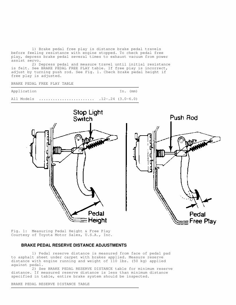
1) Brake pedal free play is distance brake pedal travelsbefore feeling resistance with engine stopped. To check pedal freeplay, depress brake pedal several times to exhaust vacuum from powerassist servo. 2) Depress pedal and measure travel until initial resistanceis felt. See BRAKE PEDAL FREE PLAY table. If free play is incorrect,adjust by turning push rod. See Fig. 1. Check brake pedal height iffree play is adjusted.
BRAKE PEDAL FREE PLAY TABLE�������������������������������������������������������������������������������������������������������������
Application In. (mm)
All Models ........................ .12-.24 (3.0-6.0)�������������������������������������������������������������������������������������������������������������
Fig. 1: Measuring Pedal Height & Free PlayCourtesy of Toyota Motor Sales, U.S.A., Inc.
BRAKE PEDAL RESERVE DISTANCE ADJUSTMENTS
1) Pedal reserve distance is measured from face of pedal padto asphalt sheet under carpet with brakes applied. Measure reservedistance with engine running and weight of 110 lbs. (50 kg) appliedagainst pedal. 2) See BRAKE PEDAL RESERVE DISTANCE table for minimum reservedistance. If measured reserve distance is less than minimum distancespecified in table, entire brake system should be inspected.
BRAKE PEDAL RESERVE DISTANCE TABLE�������������������������������������������������������������������������������������������������������������
Application In. (mm)
Celica .................................... 3.15 (80)Corolla Rear Disc Brake ........................ 2.36 (60) Rear Drum Brake ........................ 2.17 (55)MR2 ....................................... 3.43 (87)Tercel Sedan ................................... 2.20 (56) Wagon ................................... 3.54 (90)�������������������������������������������������������������������������������������������������������������
PARKING BRAKE ADJUSTMENTS
NOTE: Service brake must be correctly adjusted before adjusting parking brake.
Pull on parking brake lever with weight of 44 lbs. (20 kg) tocheck parking brake adjustment. Count number of notches (clicks) untilparking brake is fully applied. Compare actual count to specificationin PARKING BRAKE ADJUSTMENT table. Adjust parking brake if travel isincorrect.
MR2
1) Pull parking brake lever up and down several times. Leavelever in released position. Pump brake pedal several times. Removefuel tank protector. Loosen adjusting nuts at equalizer until there isslack in cable. 2) Ensure that cable bellcrank on caliper is touching stoppin. Tighten adjusting nut until cable is taut, but not so much thatbellcrank is pulled off stop pin. Tighten adjusting nuts withequalizer in horizontal position. Install fuel tank protector.
ALL OTHERS
Remove console box or parking brake lever boot to uncoverbase of lever. Turn adjusting nut on cable until lever travel iscorrect. Tighten lock nut or adjusting cap. Install console or boot.
PARKING BRAKE ADJUSTMENT TABLE�������������������������������������������������������������������������������������������������������������
Application Notches
Celica .......................................... 4-7Corolla Disc ......................................... 5-8 Drum ......................................... 4-7MR2 ............................................. 5-8Tercel Sedan ......................................... 7-9 Wagon ......................................... 6-8�������������������������������������������������������������������������������������������������������������
STOPLIGHT SWITCH ADJUSTMENTS
Stoplight switch is located above brake pedal. See Fig. 1. Toadjust, remove panel and air duct (if necessary). Loosen lock nuts andturn switch until it touches pedal stop. Tighten lock nut. Check pedalheight and brake light operation.
REMOVAL & INSTALLATION
NOTE: Location or numbers of anti-rattle springs, anti-squeal shims, pad support and guide plates will vary between models. Note component locations during removal process for reassembly reference.
FRONT PADS R & I
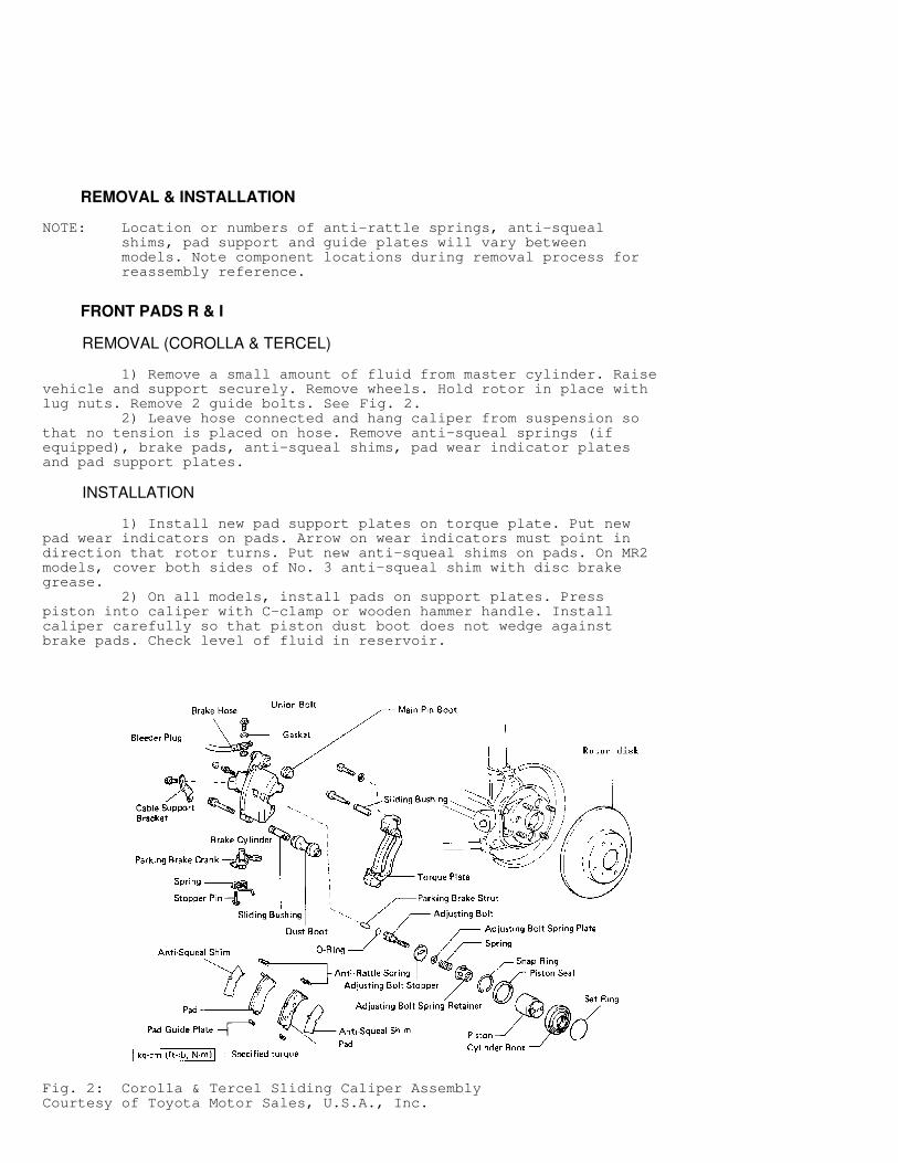
REMOVAL (COROLLA & TERCEL)
1) Remove a small amount of fluid from master cylinder. Raisevehicle and support securely. Remove wheels. Hold rotor in place withlug nuts. Remove 2 guide bolts. See Fig. 2. 2) Leave hose connected and hang caliper from suspension sothat no tension is placed on hose. Remove anti-squeal springs (ifequipped), brake pads, anti-squeal shims, pad wear indicator platesand pad support plates.
INSTALLATION
1) Install new pad support plates on torque plate. Put newpad wear indicators on pads. Arrow on wear indicators must point indirection that rotor turns. Put new anti-squeal shims on pads. On MR2models, cover both sides of No. 3 anti-squeal shim with disc brakegrease. 2) On all models, install pads on support plates. Presspiston into caliper with C-clamp or wooden hammer handle. Installcaliper carefully so that piston dust boot does not wedge againstbrake pads. Check level of fluid in reservoir.
Fig. 2: Corolla & Tercel Sliding Caliper AssemblyCourtesy of Toyota Motor Sales, U.S.A., Inc.
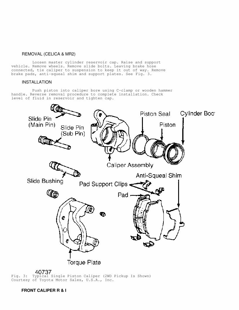
REMOVAL (CELICA & MR2)
Loosen master cylinder reservoir cap. Raise and supportvehicle. Remove wheels. Remove slide bolts. Leaving brake hoseconnected, tie caliper to suspension to keep it out of way. Removebrake pads, anti-squeal shim and support plates. See Fig. 3.
INSTALLATION
Push piston into caliper bore using C-clamp or wooden hammerhandle. Reverse removal procedure to complete installation. Checklevel of fluid in reservoir and tighten cap.
Fig. 3: Typical Single Piston Caliper (2WD Pickup Is Shown)Courtesy of Toyota Motor Sales, U.S.A., Inc.
FRONT CALIPER R & I
REMOVAL
1) Raise vehicle and remove wheel(s). Disconnect hydraulicline and spring clip. Plug line to prevent fluid spillage. Removecaliper mounting bolts or slide pins as necessary. 2) On models with fixed main pin, pivot caliper up to clearedge of rotor. Slide caliper off main pin. On all other models, removecaliper from knuckle or torque plate.
INSTALLATION
To install, reverse removal procedure. On units with fixedmain pin, boot end must be installed in groove of main pin.
REMOVAL & INSTALLATION (CELICA, COROLLA FWD, MR2 & TERCEL)
Remove caliper assembly with hose connected. Support caliperfrom frame with wire. Remove torque plate from knuckle. Slide rotoroff hub assembly. To install, reverse removal procedure.
FRONT WHEEL BEARING & OIL SEAL R & I
REMOVAL (CELICA, COROLLA FWD & TERCEL)
1) Remove cotter pin and bearing lock nut cap. Hold foot onbrake pedal and loosen bearing lock nut. Remove brake caliper fromsteering knuckle and suspend on wire. Remove brake disc. 2) Remove cotter pin and nut from end of tie rod. Removespeed sensor (if equipped). Separate tie rod end from steeringknuckle. Place matchmarks on strut housing lower bracket and camberadjustment cam for reassembly reference. 3) Separate steering knuckle from strut housing. Remove 2bolts holding lower control arm to steering knuckle. On Celica andTercel Wagon use a 2-jaw puller to remove axle hub from drive shaft.On all others, use a plastic hammer to tap drive shaft through hub. 4) Place steering knuckle in vise. Using screwdriver, removedust deflector. Using slide hammer with inside puller, pull oil sealout of steering knuckle. Remove snap ring from inside housing. Remove3 bolts holding brake dust cover to steering knuckle. 5) Using 2-jaw puller, push axle hub out of steering knuckle.Remove inside bearing inner race from bearing. Using inside puller,pull oil seal out of steering knuckle. 6) Using 2-jaw puller, pull inner race of outer bearing fromaxle hub. Install outside bearing inner race on bearing to be removed.Using press with driver and support for knuckle, press bearing out ofsteering knuckle.
INSTALLATION
1) Using press and Bearing Replacer (09316-60010) for TercelSedan, Bearing Replacer (09309-35010) for Tercel Wagon or SteeringKnuckle Oil Seal Replacer (09608-32010) for all others, press newbearing into steering knuckle. Install outside bearing inner race tobearing. 2) To install new outside oil seal to steering knuckle, useOil Seal Driver (09608-10010) for Tercel, Oil Seal Driver (09515-35010for Tercel Wagon) or Oil Seal Replacer (09608-32010) and Bushing Tool(09710-14012) for all other models. 3) Apply liquid sealer to dust cover and steering knuckleconnection and assemble. Insert axle hub into steering knuckle. Invert
steering knuckle and install inside bearing inner race. 4) For all models except Tercel Sedan, using an arbor press,Adapter (09228-22020) and Countershaft Bearing Replacer (09310-35010),press inside bearing inner race until it is tightly against shoulderof hub.
NOTE: DO NOT interchange inner and outer bearing races when installing.
5) Place steering knuckle in vise with hub facing down. Usingsnap ring pliers, install snap ring into hole of steering knuckle.Place new inside oil seal on steering knuckle hole. 6) Use Oil Seal Driver (09608-10010) for Tercel Sedan, OilSeal Driver (09309-35010) for Tercel Wagon, or Oil Seal Replacer(09608-32010) and Bushing Tool (09710-14012) for all other models. OnTercel Wagon, seal should be positioned .13" (3.3 mm) from endsurface. 7) Using Adapter (09608-16050) for Tercel Wagon or CrankshaftRear Oil Seal Replacer (09223-41020) for all models except Tercel,drive new dust deflector into steering knuckle. On Tercel, installbolts. On all models, install steering knuckle assembly to lower arm.Install axle hub to drive shaft.
CAUTION: Be careful not to damage oil seal lip or drive shaft boot.
8) Reverse removal procedure to complete installation. Whiledepressing brake pedal, tighten lock nut to 137 ft. lbs. (186 N.m).Install lock nut cap and cotter pin. Check front wheel alignment.
REAR PADS R & I
NOTE: Pushing piston into caliper bore will force fluid back into master cylinder reservoir.
REMOVAL
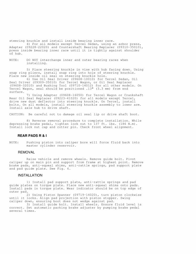
Raise vehicle and remove wheels. Remove guide bolt. Pivotcaliper up on main pin and support from frame at highest point. Removebrake pads, anti-squeal shims, anti-rattle springs, pad support plateand pad guide plate. See Fig. 4.
INSTALLATION
1) Install pad support plate, anti-rattle springs and padguide plates on torque plate. Place new anti-squeal shims onto pads.Install pads in torque plate. Wear indicator should be on top edge ofouter pad. 2) Using Piston Spanner (09719-14020), turn piston clockwiseuntil it locks. Align pad projection with piston stopper. Swingcaliper down, ensuring boot does not wedge against pad. 3) Install guide bolt. Install wheels. Ensure fluid level iscorrect. Set automatic parking brake adjuster by pumping brake pedalseveral times.
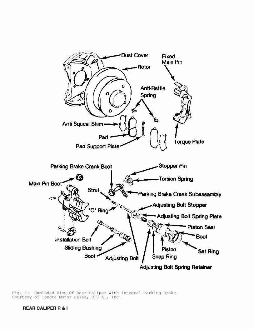
Fig. 4: Exploded View Of Rear Caliper With Integral Parking BrakeCourtesy of Toyota Motor Sales, U.S.A., Inc.
REAR CALIPER R & I
REMOVAL
Disconnect brake hose and mounting bolts. Disconnect parkingbrake cable if attached to caliper. On fixed pin type caliper, pivotcaliper up to clear rotor and slide it off main pin. On all othermodels, remove caliper from knuckle or torque plate.
INSTALLATION
To install, reverse removal procedure. On fixed pin typecaliper, ensure that boot end is installed in groove of pin. On modelswith integral parking brake, align pad projection with piston stoppergroove.
REAR ROTOR R & I
REMOVAL & INSTALLATION
Remove caliper and suspend from underbody with hoseconnected. Remove torque plate from backing plate. Slide rotor offaxle flange. To install, reverse removal procedure.
REAR PARKING BRAKE R & I
REMOVAL (INTERNAL SHOE BRAKE)
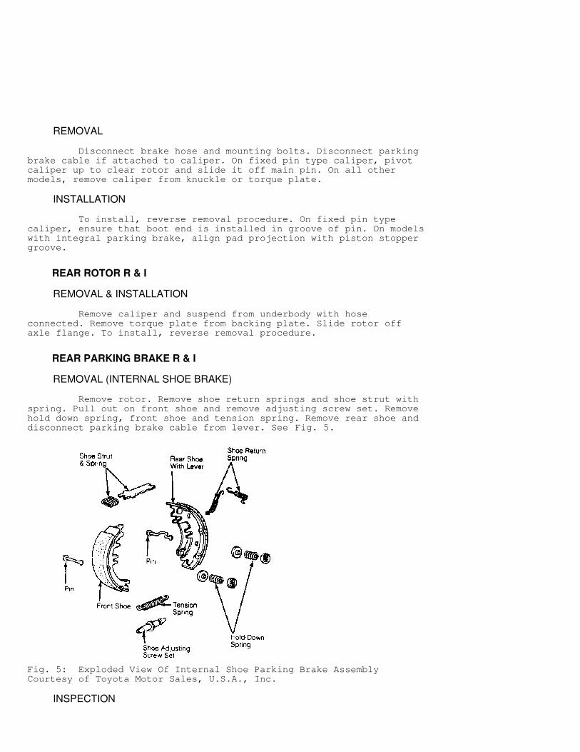
Remove rotor. Remove shoe return springs and shoe strut withspring. Pull out on front shoe and remove adjusting screw set. Removehold down spring, front shoe and tension spring. Remove rear shoe anddisconnect parking brake cable from lever. See Fig. 5.
Fig. 5: Exploded View Of Internal Shoe Parking Brake AssemblyCourtesy of Toyota Motor Sales, U.S.A., Inc.
INSPECTION
Clearance between parking brake shoe and lever must be within.014" (.35 mm). If not, replace shim under parking brake lever. Shimsare available in .008-.035" (.20-.90 mm) and .004" (.10 mm)increments. Use new "C" washer when installing lever.
INSTALLATION
Reverse removal procedure to complete installation. Applynon-melting grease to sliding surfaces of shoes and adjusting screwthreads. Align groove of rear axle shaft flange with service hole ondisc and install disc.
REAR DRUM R & I
REMOVAL (TERCEL SEDAN)
Raise and support vehicle. Remove tire and wheel. Removegrease cap, cotter pin, lock nut and bearing nut. Remove brake hubtogether with outer bearing and thrust washer.
REMOVAL (ALL OTHERS)
Raise and support vehicle. Remove tire and wheel. Remove setscrews from brake drum (if equipped). Pull drum from axle flange. Itmay be necessary to loosen brake adjustment before removing drum.
INSTALLATION
1) Measure inside diameter of brake drum and diameter ofbrake shoes. Turn brake adjuster until difference between diameters is.02" (.6 mm). On all models except Tercel Sedan, install brake drumand adjust brakes, if required. 2) On Tercel Sedan, pack wheel bearings with MP grease.Tighten wheel bearings to 22 ft. lbs. (30 N.m) while turning drum.Loosen nut until it can be turned by hand. Install cotter pin. If pinwill not go into hole in spindle, loosen nut to obtain alignment.
REAR BRAKE SHOES R & I
REMOVAL (TERCEL SEDAN)
1) With brake drum removed, disconnect return spring. Removehold-down springs and pins. Disconnect front shoe from parking brakestrut and disconnect lower spring. Remove front shoe. Disconnectparking brake lever return spring. 2) Remove rear shoe from backing plate. Disconnect parkingbrake cable from lever. Remove "C" washer, adjusting lever and parkingbrake lever from rear shoe. Remove "C" washer retaining parking brakelever on adjusting lever and separate levers. See Fig. 6.
INSTALLATION
Install parking brake lever onto adjusting lever with new "C"washer. Ensure that lever moves. Complete installation by reversingremoval procedure. Install drum and bleed hydraulic system.
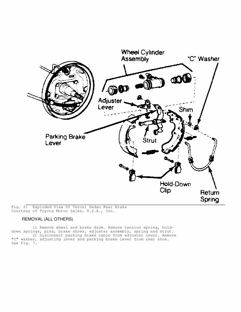
Fig. 6: Exploded View Of Tercel Sedan Rear BrakeCourtesy of Toyota Motor Sales, U.S.A., Inc.
REMOVAL (ALL OTHERS)
1) Remove wheel and brake drum. Remove tension spring, hold-down springs, pins, brake shoes, adjuster assembly, spring and strut. 2) Disconnect parking brake cable from adjuster lever. Remove"C" washer, adjusting lever and parking brake lever from rear shoe.See Fig. 7.
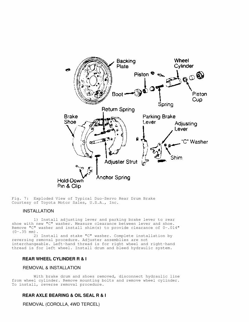
Fig. 7: Exploded View of Typical Duo-Servo Rear Drum BrakeCourtesy of Toyota Motor Sales, U.S.A., Inc.
INSTALLATION
1) Install adjusting lever and parking brake lever to rearshoe with new "C" washer. Measure clearance between lever and shoe.Remove "C" washer and install shim(s) to provide clearance of 0-.014"(0-.35 mm). 2) Install and stake "C" washer. Complete installation byreversing removal procedure. Adjuster assemblies are notinterchangeable. Left-hand thread is for right wheel and right-handthread is for left wheel. Install drum and bleed hydraulic system.
REAR WHEEL CYLINDER R & I
REMOVAL & INSTALLATION
With brake drum and shoes removed, disconnect hydraulic linefrom wheel cylinder. Remove mounting bolts and remove wheel cylinder.To install, reverse removal procedure.
REAR AXLE BEARING & OIL SEAL R & I
REMOVAL (COROLLA, 4WD TERCEL)
1) With wheel and brake drum removed, remove 4 backing platemounting nuts. Using Axle Shaft Puller (09520-00031), remove axleshaft. Maximum shaft runout is .059" (1.5 mm). 2) Maximum flange runout is .004" (.1 mm). Using grinder,grind down inner bearing retainer of axle shaft and cut off withchisel and hammer. 3) Using Adapter (09527-30010 for Corolla with disc brake or09527-20011 for all others) and press, remove bearing from axle shaft.Use seal puller to remove oil seal from housing. Clean all parts.
INSTALLATION
1) Position outer bearing retainer and new bearing on axleshaft. Using press and Adapter (09515-21010) for Corolla, or Adapter(09515-20010) for Tercel, press bearing onto axle shaft. 2) Heat new inner bearing retainer to 302
�
F (150�
C) in oilbath. While still hot, face non-beveled side toward bearing and pressonto axle shaft, using Adapter (09515-21010) for Corolla, or Adapter(09515-20010) for Tercel.
NOTE: When installing hot inner bearing retainer, make sure there is no oil or grease on axle shaft.
3) Use seal driver to install new oil seal in rear axlehousing. Set oil seal depth .079" (2.0 mm) for Corolla with discbrakes, .232" (5.9 mm) for Corolla with drum brakes, and .220" (5.6mm) for Tercel below outer edge of housing. 4) With bearing retainer and gasket assembly on axle shaft,align and position with notches facing down. Install axle shaft intohousing and tighten mounting nuts to 44-53 ft. lbs. (60-72 N.m).Complete installation by reversing removal procedures.
MASTER CYLINDER R & I
REMOVAL
On MR2, remove luggage compartment trim cover. On all models,unplug sensor lead (if equipped). Remove brake fluid from reservoir.Disconnect and plug hydraulic lines. Remove nuts holding mastercylinder to power assist servo. Remove master cylinder.
INSTALLATION
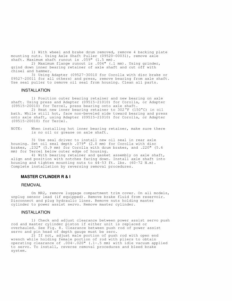
1) Check and adjust clearance between power assist servo pushrod and master cylinder piston if either unit is replaced oroverhauled. See Fig. 8. Clearance between push rod of power assistservo and pin head of depth gauge must be zero. 2) If not, adjust male portion of push rod with open endwrench while holding female portion of rod with pliers to obtainoperating clearance of .004-.020" (.1-.5 mm) with idle vacuum appliedto servo. To install, reverse removal procedures and bleed brakesystem.
Fig. 8: Measuring Clearance Between Master Cylinder & PowerAssist ServoCourtesy of Toyota Motor Sales, U.S.A., Inc.
POWER ASSIST SERVO R & I
REMOVAL & INSTALLATION
Remove master cylinder assembly from vehicle. On MR2, removeinstrument panel lower trim panel. On all models, disconnect push rodclevis at brake pedal. Remove power booster attaching hardware andbooster assembly from vehicle. To install, reverse removal procedure.
LOAD SENSING PROPORTIONING VALVE (LSPV) R & I
REMOVAL
Raise and support vehicle. Disconnect No. 2 shackle frombracket. Disconnect and plug hydraulic lines from LSPV. Remove clipfrom brake hose. Remove mounting bolts from valve bracket and removeLSPV assembly. Separate valve body from bracket.
INSTALLATION
To install, reverse removal procedure. Apply rubber grease toall rubbing areas. Install new rubber plate on valve body side ofspring. Adjust length of upper and lower shackle to original height.Bleed hydraulic system and check brake pressures.
FRONT CALIPER OVERHAUL
NOTE: When overhauling caliper, if cylinder bores are pitted or scored more than light honing will repair, replace entire assembly.
DISASSEMBLY
Remove retainer ring (if equipped) and dust boot. Insertsmall wooden block between pistons. Apply light air pressure to fluidinlet port to remove piston from cylinder. Remove seal from cylinderwithout damaging bore.
CLEANING & INSPECTION
Clean all parts in clean brake fluid or alcohol. Inspect bore
and piston for excessive wear or damage. Replace defective parts.
REASSEMBLY
Coat piston, seal and cylinder bore with clean brake fluid orassembly lube. To reassemble, reverse disassembly procedure.
REAR CALIPER OVERHAUL
DISASSEMBLY (CELICA)
Remove sliding bushing and boot. Remove piston from caliperusing compressed air in fluid hole to force piston. DO NOT placefingers in front of piston while blowing into caliper with compressedair. Remove caliper boot and retaining ring from cylinder. Removepiston seal from caliper.
CLEANING & INSPECTION
Wash all parts in clean brake fluid or alcohol. Inspect allparts for excessive wear, damage and corrosion. Replace defectiveparts.
REASSEMBLY
Coat main pin boot, sliding pin and boot, piston seal, pistonand dust boot with lithium soap base glycol. Install piston seal andpiston into caliper. Install dust boot and retaining ring in caliper.Install sliding bushing and boot. Bushing flange must face towardinside of caliper.
DISASSEMBLY (COROLLA & MR2)
1) Remove sliding bushing and boot. On MR2 model, remove mainpin boot. On all models use screwdriver to remove retaining ring anddust boot. Using Piston Spanner (09719-14020), remove piston from boreby turning it clockwise. Remove piston seal from bore of cylinder. 2) Using Spring Compressor (09756-00010) over adjusting bolt,gently tighten spring with 14 mm socket. Remove snap ring from bore ofcaliper. Remove Spring Compressor.
CAUTION: Always use Spring Compressor (09756-00010) when removing snap ring to prevent involuntary spring disengagement. DO NOT overtighten spring compressor as spring retainer could be damaged.
3) Pull spring retainer, spring, spring plate and stopper outwith adjusting bolt connected. DO NOT use excessive force to pry outadjusting bolt. Be very careful of "O" ring on adjusting bolt.Disassemble adjusting bolt by removing retainer, spring, spring plateand stopper. Remove "O" ring from bolt. 4) Remove strut. Remove spring from parking brake lever.Remove parking brake lever from caliper. On Corolla models, turn leverso it will not catch on stop pin. Do not disassemble lever anyfurther. If lever boot is to be replaced, remove it. On MR2, removecable support bracket and stopper pin.
REASSEMBLY
1) Put lithium soap base glycol grease on main pin, slidingbushing, strut pin, adjusting bolt, piston and all rubber parts. On
MR2 models, install stopper pin. Pin should be .098" (2.5 mm) fromcaliper to underside of head. 2) Install cable support bracket. On all models, installlever boot. Install lever, ensuring boot aligns with groove in leverseal. On MR2 models, ensure lever clears overlap on caliper. On allmodels, install spring and ensure that lever touches stopper pin. 3) On Corolla, make sure that clearance between cable supportbracket and upper side of lever is .0197-.0275" (.5-.7 mm). Use cablesupport bracket mount bolt to adjust clearance. 4) On all models, install strut. Ensure needle rollers do notcatch on caliper hole. Install new "O" ring on adjusting bolt.Reassemble adjuster bolt with stopper, plate, spring and springretainer. 5) Use threaded compressor to tighten component parts ofadjusting bolt assembly. Ensure that inscribed surface of stopperfaces UP and notches of spring case line up with notches on stopper. 6) Install adjusting bolt assembly. Install snap ring withopening toward bleeder side. Remove threaded compressor. Move parkingbrake lever by hand. Ensure adjusting bolt moves smoothly. Installpiston seal in bore of cylinder. 7) Using piston spanner, slowly turn piston clockwise intocaliper until it bottoms. Center of piston stopper groove must alignwith projection on caliper. Place dust boot and retaining ring intocaliper. Install sliding bushing and boot. Ensure seal does not foldunder piston.
MASTER CYLINDER OVERHAUL
DISASSEMBLY
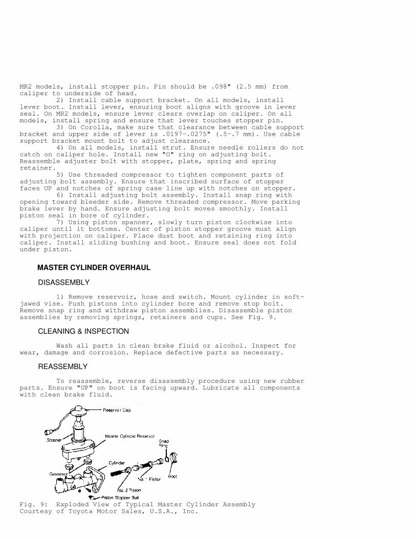
1) Remove reservoir, hose and switch. Mount cylinder in soft-jawed vise. Push pistons into cylinder bore and remove stop bolt.Remove snap ring and withdraw piston assemblies. Disassemble pistonassemblies by removing springs, retainers and cups. See Fig. 9.
CLEANING & INSPECTION
Wash all parts in clean brake fluid or alcohol. Inspect forwear, damage and corrosion. Replace defective parts as necessary.
REASSEMBLY
To reassemble, reverse disassembly procedure using new rubberparts. Ensure "UP" on boot is facing upward. Lubricate all componentswith clean brake fluid.
Fig. 9: Exploded View of Typical Master Cylinder AssemblyCourtesy of Toyota Motor Sales, U.S.A., Inc.
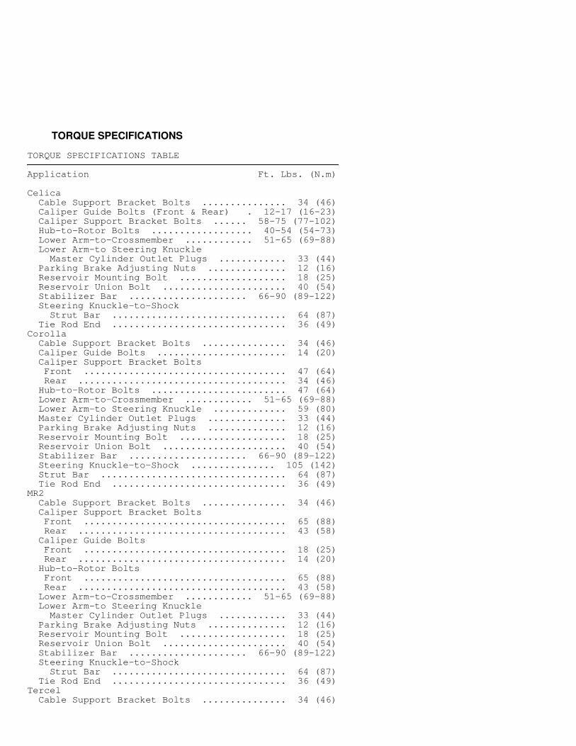
TORQUE SPECIFICATIONS
TORQUE SPECIFICATIONS TABLE�������������������������������������������������������������������������������������������������������������
Application Ft. Lbs. (N.m)
Celica Cable Support Bracket Bolts ............... 34 (46) Caliper Guide Bolts (Front & Rear) . 12-17 (16-23) Caliper Support Bracket Bolts ...... 58-75 (77-102) Hub-to-Rotor Bolts .................. 40-54 (54-73) Lower Arm-to-Crossmember ............ 51-65 (69-88) Lower Arm-to Steering Knuckle Master Cylinder Outlet Plugs ............ 33 (44) Parking Brake Adjusting Nuts .............. 12 (16) Reservoir Mounting Bolt ................... 18 (25) Reservoir Union Bolt ...................... 40 (54) Stabilizer Bar ..................... 66-90 (89-122) Steering Knuckle-to-Shock Strut Bar ............................... 64 (87) Tie Rod End ............................... 36 (49)Corolla Cable Support Bracket Bolts ............... 34 (46) Caliper Guide Bolts ....................... 14 (20) Caliper Support Bracket Bolts Front .................................... 47 (64) Rear ..................................... 34 (46) Hub-to-Rotor Bolts ........................ 47 (64) Lower Arm-to-Crossmember ............ 51-65 (69-88) Lower Arm-to Steering Knuckle ............. 59 (80) Master Cylinder Outlet Plugs .............. 33 (44) Parking Brake Adjusting Nuts .............. 12 (16) Reservoir Mounting Bolt ................... 18 (25) Reservoir Union Bolt ...................... 40 (54) Stabilizer Bar ..................... 66-90 (89-122) Steering Knuckle-to-Shock ............... 105 (142) Strut Bar ................................. 64 (87) Tie Rod End ............................... 36 (49)MR2 Cable Support Bracket Bolts ............... 34 (46) Caliper Support Bracket Bolts Front .................................... 65 (88) Rear ..................................... 43 (58) Caliper Guide Bolts Front .................................... 18 (25) Rear ..................................... 14 (20) Hub-to-Rotor Bolts Front .................................... 65 (88) Rear ..................................... 43 (58) Lower Arm-to-Crossmember ............ 51-65 (69-88) Lower Arm-to Steering Knuckle Master Cylinder Outlet Plugs ............ 33 (44) Parking Brake Adjusting Nuts .............. 12 (16) Reservoir Mounting Bolt ................... 18 (25) Reservoir Union Bolt ...................... 40 (54) Stabilizer Bar ..................... 66-90 (89-122) Steering Knuckle-to-Shock Strut Bar ............................... 64 (87) Tie Rod End ............................... 36 (49)Tercel Cable Support Bracket Bolts ............... 34 (46)
Caliper Support Bracket Bolts ............. 65 (88) Caliper Guide Bolts ....................... 18 (25) Hub-to-Rotor Bolts .................. 29-39 (39-53) Lower Arm-to-Crossmember ............ 51-65 (69-88) Lower Arm-to Steering Knuckle Master Cylinder Outlet Plugs ............ 33 (44) Parking Brake Adjusting Nuts .............. 12 (16) Reservoir Mounting Bolt ................... 18 (25) Reservoir Union Bolt ...................... 40 (54) Stabilizer Bar ..................... 66-90 (89-122) Steering Knuckle-to-Shock Strut Bar ............................... 64 (87) Tie Rod End ............................... 36 (49)
INCH Lbs. (N.m)
Bleeder Plug ............................... 72 (8) Brake Booster Mounting Nuts .............. 108 (13) Line-to-Wheel Cylinder ................... 132 (15) Master Cylinder Brake Hoses .............. 132 (15)�������������������������������������������������������������������������������������������������������������
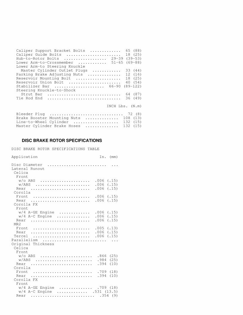
DISC BRAKE ROTOR SPECIFICATIONS
DISC BRAKE ROTOR SPECIFICATIONS TABLE�����������������������������������������������������������������������������������������
Application In. (mm)
Disc Diameter ......................... ...Lateral Runout Celica Front w/o ABS ..................... .006 (.15) w/ABS ....................... .006 (.15) Rear ......................... .006 (.15) Corolla Front ........................ .006 (.15) Rear ......................... .006 (.15) Corolla FX Front w/4 A-GE Engine ............. .006 (.15) w/4 A-C Engine .............. .006 (.15) Rear ......................... .006 (.15) MR2 Front ........................ .005 (.13) Rear ......................... .006 (.15) Tercel ........................ .006 (.15)Parallelism ........................... ...Original Thickness Celica Front w/o ABS ...................... .866 (25) w/ABS ........................ .984 (25) Rear .......................... .394 (10) Corolla Front ......................... .709 (18) Rear .......................... .394 (10) Corolla FX Front w/4 A-GE Engine .............. .709 (18) w/4 A-C Engine ............. .531 (13.5) Rear ........................... .354 (9)
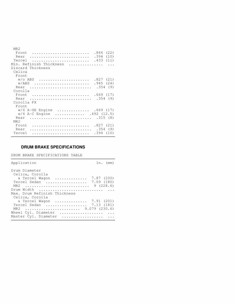
MR2 Front ......................... .866 (22) Rear .......................... .394 (10) Tercel ......................... .433 (11)Min. Refinish Thickness ............... ...Discard Thickness Celica Front w/o ABS ...................... .827 (21) w/ABS ........................ .945 (24) Rear ........................... .354 (9) Corolla Front ......................... .669 (17) Rear ........................... .354 (9) Corolla FX Front w/4 A-GE Engine .............. .669 (17) w/4 A-C Engine ............. .492 (12.5) Rear ........................... .315 (8) MR2 Front ......................... .827 (21) Rear ........................... .354 (9) Tercel ......................... .394 (10)�����������������������������������������������������������������������������������������
DRUM BRAKE SPECIFICATIONS
DRUM BRAKE SPECIFICATIONS TABLE�����������������������������������������������������������������������������������������
Application In. (mm)
Drum Diameter Celica, Corolla & Tercel Wagon .............. 7.87 (200) Tercel Sedan .................. 7.09 (180) MR2 ............................ 9 (228.6)Drum Width ............................ ...Max. Drum Refinish Thickness Celica, Corolla & Tercel Wagon .............. 7.91 (201) Tercel Sedan .................. 7.13 (181) MR2 ........................ 9.079 (230.6)Wheel Cyl. Diameter ................... ...Master Cyl. Diameter .................. ...�����������������������������������������������������������������������������������������
Related Documents