Rapid Prototyping

Welcome message from author
This document is posted to help you gain knowledge. Please leave a comment to let me know what you think about it! Share it to your friends and learn new things together.
Transcript
Rapid Prototyping
2
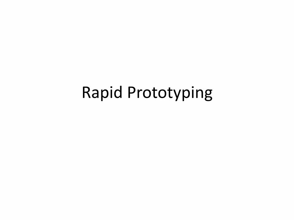
What is Prototyping?
Prototype is the first or original example of something that has been developed; it is a model or preliminary version.
Need for a prototype: It is a tool for a designer to validate his design before starting the actual production of the component.
Methods of making prototypes:
Manual prototyping (Traditional practice)
Machining/CNC method (Recent practice)
Issues: Time consuming and costly

3
Product Development
4
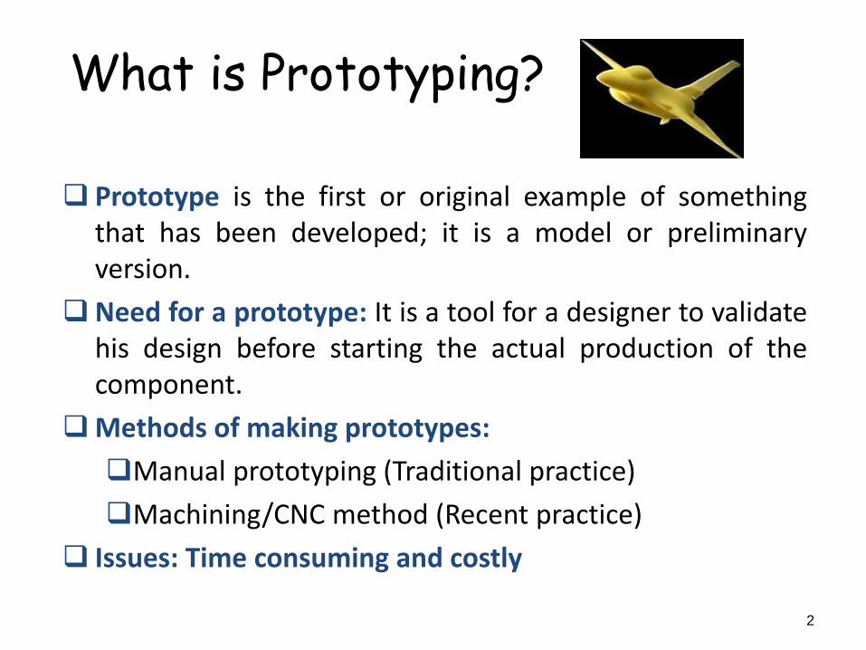
What is Rapid Prototyping????
• A technology that produces models and prototype
parts from 3D computer-aided design (CAD) model
data, CT and MRI scan data, and model data
created from 3D object digitizing systems.
• Direct fabrication of parts, components, or models
from 3D CAD drawings WITHOUT part-specific
tooling or human intervention”.
5
Benefits of Rapid Prototyping
Reduced lead times to produce prototyped components
Improved ability to visualize the part geometry due to its physical existence
Earlier detection and reduction of design errors
Increased capability to compute mass properties of components and assemblies
Eliminates waste and costly late changes
6
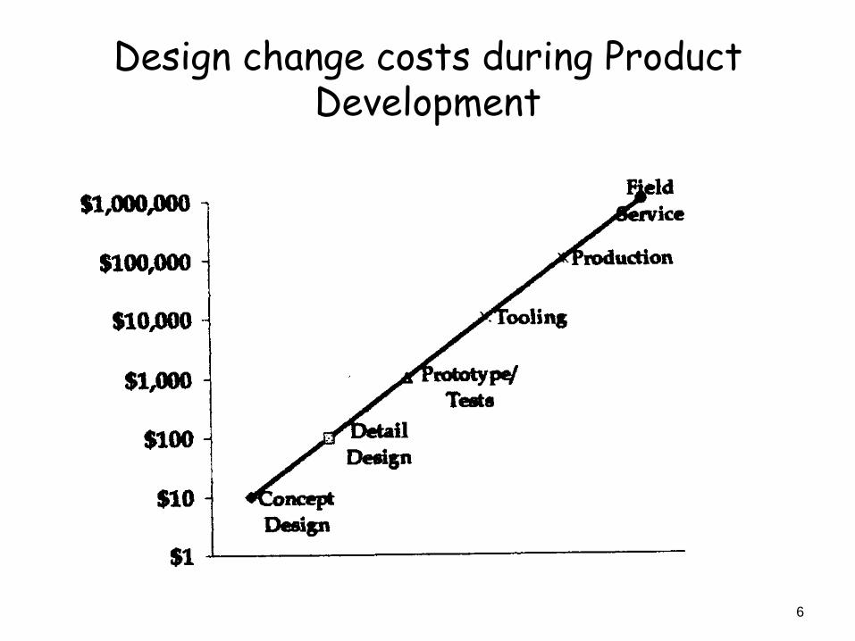
Design change costs during Product Development

Principle of Rapid Prototyping
CAD Model 1
2
3
Sliced Model
Layered Manufacturing
8
The first step in RP is the creation of a CAD solid model
RP requires that we make a fully closed, water-tight model such that even if we were to pour water into the volume of the model, it would not leak
Solid models can be created using a CAD softwares/tools
Step 1: Creating CAD Model
9
Step 2: Conversion of CAD Model into STL
Since various CAD software packages use different algorithms to represent solid objects, STL file format has been selected as the de facto standard in the RP industry
The STL file represents a 3D surface of an assembly as planar triangles
The file contains the coordinates of the vertices and the direction of the outward normal of each triangle
The STL file format is the best file format to represent all surfaces, in preparation for the slicing algorithm
10
Step 3: Slicing the STL file
Slicing the STL file using a proprietary software program, provided by the manufacturer of the RP machine in which the model is to be produced
The software imports the STL file and lets the user orient the part and adjust the size and slice thickness (0.01 to 0.7mm) of the model
The software also generate support structure, these are necessary for creating features such as overhangs, internal cavities and thin-walled sections
It also provides information about how much time and material will be required to make the prototype
11
Step 4: Growing the prototype
It involves the actual making of the prototype
Once the STL file is processed and saved, it is sent to the RP machine
At this time, the RP machine acts as a printer
Building the prototype one layer at a time
Most of the modern RP machines can operate unattended once the initial setup is completed
12
Step 5: Postprocessing
The final step is removing the part from the machine and cleaning it before use
It also involves post curing of photosensitive materials, sintering powder materials, and removing the support materials
Some prototypes are also subjected to surface treatment, such as sanding, scaling or painting to improve their appearance and durability
13
Classification
• RP systems can be classified in a variety of
ways depending on the physics of the
process, the source of energy, type of
material, size of prototypes, and the like
• Classification based on the initial form of the
material
1. Liquid-based (SLA)
2. Solid-based (FDM)
3. Powder-based (SLS, LENS,3DP)
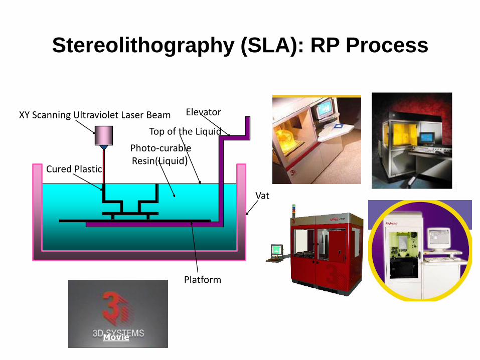
Stereolithography (SLA): RP Process
Cured Plastic
XY Scanning Ultraviolet Laser Beam
Photo-curable Resin(Liquid)
Top of the Liquid
Elevator
Vat
Platform
Movie
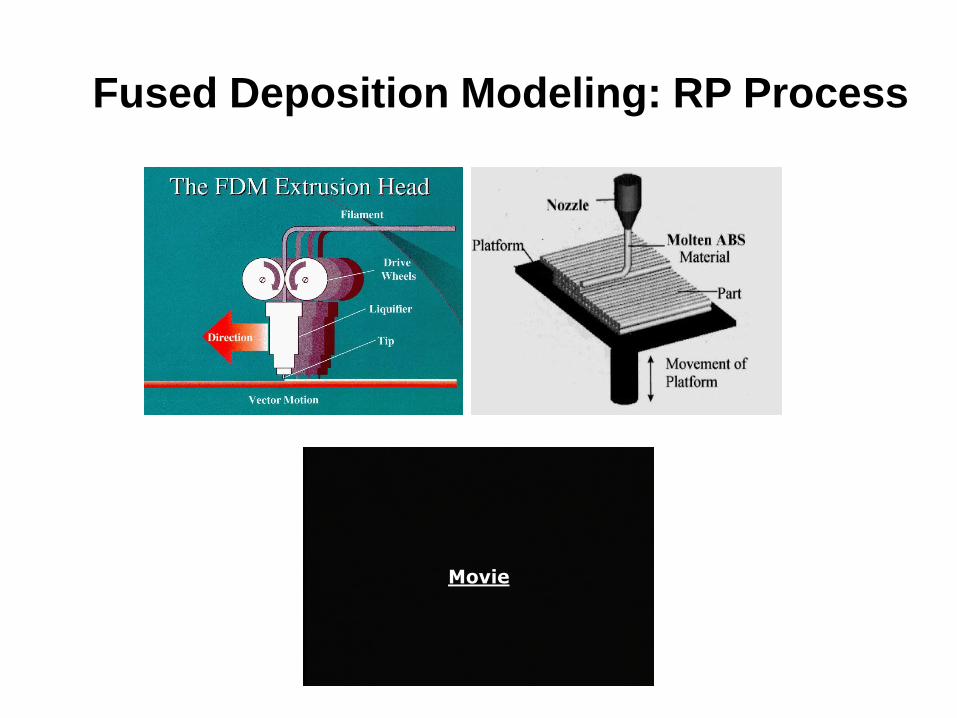
Fused Deposition Modeling: RP Process
Movie
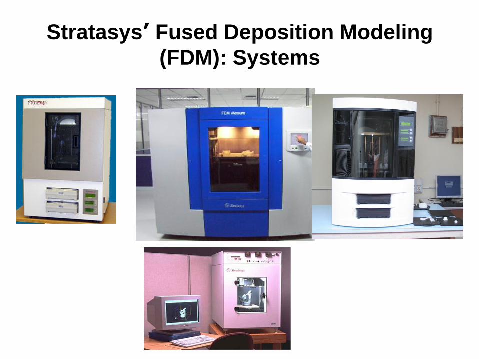
Stratasys’ Fused Deposition Modeling
(FDM): Systems
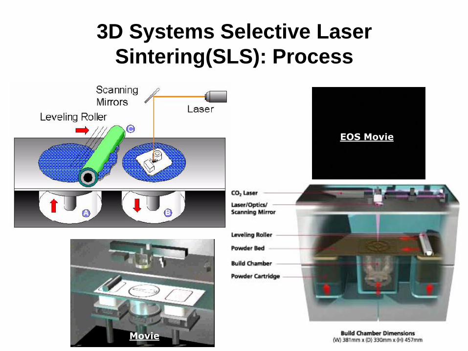
3D Systems Selective Laser
Sintering(SLS): Process
Movie
EOS Movie
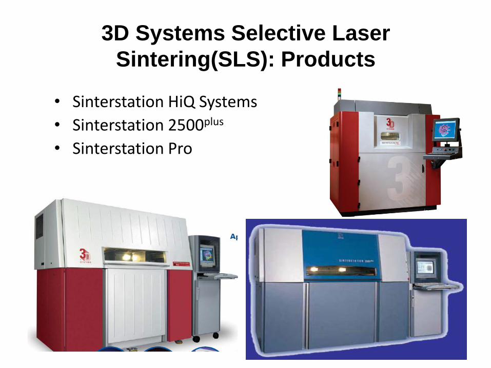
3D Systems Selective Laser
Sintering(SLS): Products
• Sinterstation HiQ Systems
• Sinterstation 2500plus
• Sinterstation Pro

Z Corporation’s 3 Dimensional Printing
(3DP): RP Process
Movie
4/22/2013 NIT, Warangal 20
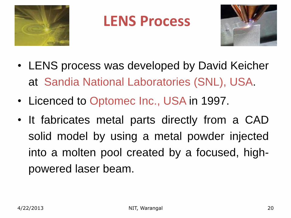
LENS Process
• LENS process was developed by David Keicher
at Sandia National Laboratories (SNL), USA.
• Licenced to Optomec Inc., USA in 1997.
• It fabricates metal parts directly from a CAD
solid model by using a metal powder injected
into a molten pool created by a focused, high-
powered laser beam.
4/22/2013 NIT, Warangal 21
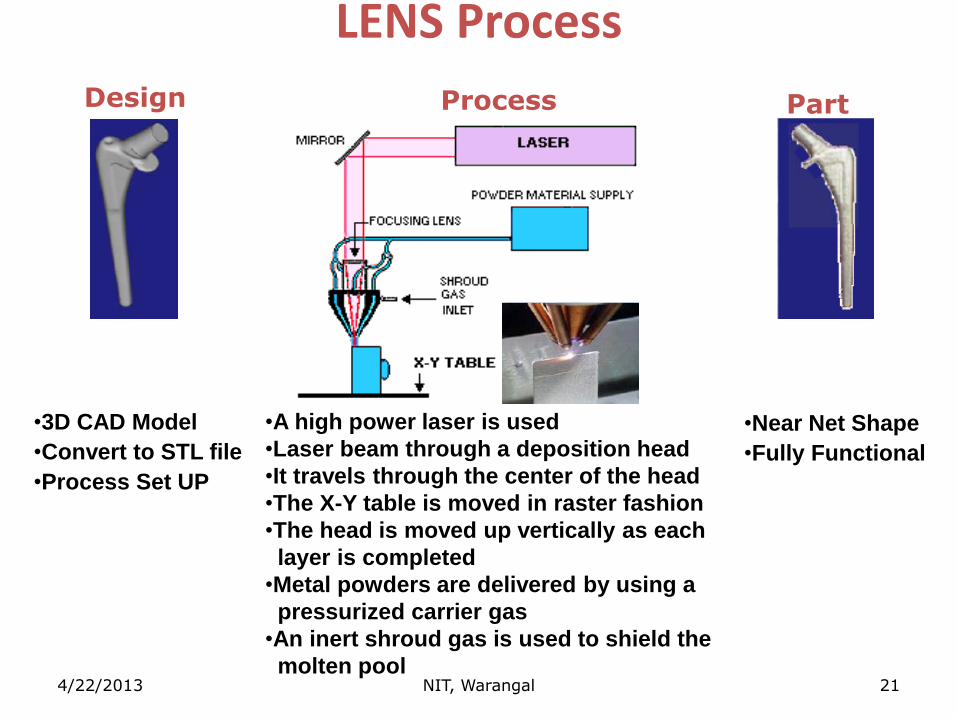
LENS Process
•3D CAD Model
•Convert to STL file
•Process Set UP
•A high power laser is used
•Laser beam through a deposition head
•It travels through the center of the head
•The X-Y table is moved in raster fashion
•The head is moved up vertically as each
layer is completed
•Metal powders are delivered by using a
pressurized carrier gas
•An inert shroud gas is used to shield the
molten pool
•Near Net Shape
•Fully Functional
Part Process Design
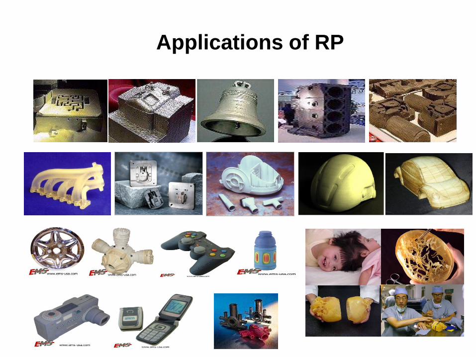
Applications of RP
Related Documents