High-Performance Embedded Systems: Architectures, Algorithms, and Applications Wayne Wolf Princeton University June 13, 2005 Description High-Performance Embedded Systems focuses on the unique complexities of embedded system design. Designed as a textbook for advanced undergraduates and graduate students in CS, CE, and EE advanced embedded computing courses, it covers advanced topics in embedded computing, including multiprocessors, a comprehensive view of processors (VLIW and superscalar architectures), and power consumption. It provides advanced treatment of all the components of the system as well as in-depth coverage of networks, reconfigurable systems, hardware-software co-design, security, and program analysis. A discussion of current industry development software includes Linux and Windows CE. Examples feature the Freescale DSP with the TI C5000 and C6000 series. Real-world applications will include DVD players and cell phones. Audience Advanced undergraduates and graduate students in CS, CE, and EE advanced embedded computing courses Pre-requisites C programming. Basic background in embedded computing: o Instruction sets and undergraduate-level computer architecture o I/O programming o Basic concepts in real-time scheduling Outline The outline below describes both the actual structure/content of completed first draft chapters and the proposed structure/content of chapters still in development. For unfinished chapters, keep in mind that the structure is approximate and the content subject to change. (Reviewers of early, incomplete drafts of 5 and 6 should note that these chapters will undergo significant revision based on their previous feedback. For the purposes of this outline, I am showing them as ‘in development’.) Changes from earlier versions of the outline are indicated in RED. Chapter 1: Embedded Computing (1 st draft completed) Covers: Fundamental problems in embedded computing Design methodologies for embedded systems

Welcome message from author
This document is posted to help you gain knowledge. Please leave a comment to let me know what you think about it! Share it to your friends and learn new things together.
Transcript
High-Performance Embedded Systems: Architectures, Algorithms, and Applications Wayne Wolf Princeton University June 13, 2005 Description High-Performance Embedded Systems focuses on the unique complexities of embedded system design. Designed as a textbook for advanced undergraduates and graduate students in CS, CE, and EE advanced embedded computing courses, it covers advanced topics in embedded computing, including multiprocessors, a comprehensive view of processors (VLIW and superscalar architectures), and power consumption. It provides advanced treatment of all the components of the system as well as in-depth coverage of networks, reconfigurable systems, hardware-software co-design, security, and program analysis. A discussion of current industry development software includes Linux and Windows CE. Examples feature the Freescale DSP with the TI C5000 and C6000 series. Real-world applications will include DVD players and cell phones. Audience Advanced undergraduates and graduate students in CS, CE, and EE advanced embedded computing courses Pre-requisites
C programming. Basic background in embedded computing:
o Instruction sets and undergraduate-level computer architecture o I/O programming o Basic concepts in real-time scheduling
Outline The outline below describes both the actual structure/content of completed first draft chapters and the proposed structure/content of chapters still in development. For unfinished chapters, keep in mind that the structure is approximate and the content subject to change. (Reviewers of early, incomplete drafts of 5 and 6 should note that these chapters will undergo significant revision based on their previous feedback. For the purposes of this outline, I am showing them as ‘in development’.) Changes from earlier versions of the outline are indicated in RED. Chapter 1: Embedded Computing (1st draft completed) Covers:
Fundamental problems in embedded computing Design methodologies for embedded systems
Models of computation Reliability and security Applications that make use of embedded computing
1.1 The Landscape of High-Performance Embedded Computing 1 1.2 Design Methodologies 4
1.2.1 Basic Design Methodologies 5 1.2.2 Embedded Systems Design Flows 7 1.2.3 Standards-Based Design Methodologies 9 1.2.4 A Methodology of Methodologies 12 1.2.5 Joint Algorithm and Architecture Development 12
1.3 Models of Computation 13 1.3.1 Why Study Models of Computation? 13 1.3.2 Finite vs. Infinite State 14 1.3.3 Parallelism and Communication 21 1.3.4 Control Flow and Data Flow Models 25
1.4 Reliability, Safety, and Security 1.4.1 Why Reliable Embedded Systems? 30 1.4.2 Fundamentals of Reliable System Design 31 1.4.3 Novel Attacks and Countermeasures 34
1.5 Example Applications 36 1.5.1 Radio and Networking 38 1.5.2 Multimedia 40
1.6 Summary What We Learned 44 Further Reading 44 Questions 44 Lab Exercises 45 Chapter 2: CPUs (1st draft completed) Covers:
Architectural mechanisms for embedded processors Parallelism in embedded CPUs Code compression and bus encoding Security mechanisms CPU simulation
2.1 Introduction 2.2 Comparing Processors 2.2.1 Evaluating Processors 2.2.2 A Taxonomy of Processors 2.3 RISC Processors and Digital Signal Processors 2.3.1 RISC Processors 2.3.2 Digital Signal Processors 2.4 Parallel Execution Mechanisms 2.4.1 Very Long Instruction Word Processors 2.4.2 Superscalar Processors 2.4.3 SIMD and Vector Processors 2.4.4 Thread-Level Parallelism
2.4.5 Processor Resource Utilization 2.5 Variable-Performance CPU Architectures 2.5.1 Dynamic Voltage and Frequency Scaling 2.5.2 Better-Than-Worst-Case Design 2.6 Processor Memory Hierarachy 2.6.1 Memory Component Models 2.6.2 Register Files 2.6.3 Caches 2.6.4 Scratch Pad Memories 2.7 Additional CPU Mechanisms 2.7.1 Code Compression 2.7.2 Low-Power Bus Encoding 2.7.3 Security 2.8 CPU Simulation 2.8.1 Trace-Based Analysis 2.8.2 Direct Execution 2.8.2 Microarchitecture-Modeling Simulators 2.9 Automated CPU Design 2.9.1 Configurable Processors 2.9.2 Instruction Set Synthesis 2.10 Summary What We Learned Further Reading Questions Lab Exercises
Chapter 3: Programs (in development) Proposed coverage:
Program performance and power analysis Emerging programming models Just-in-time compilation.
3.1 Program performance evaluation: direct measurement on hardware, simulation, worst-case execution time (WCET) analysis Direct measurement techniques Architecture simulators, how to gather traces, how to use the simulator How to compute WCET Example: motion estimation for video compression Example: Performance estimation of total MPEG-2 application 3.2 Just-in-time (JIT) code: compilation methods 3.3 Dynamically allocated data structures: usage in embedded systems; performance analysis 3.4 Program specification and synthesis (newly added) Synchronous dataflow graph: specification, synthesis Synchronous languages: specification, analysis, synthesis 3.5 Models of computation: composition of heterogeneous models (newly added) 3.6 Model-based program synthesis What is a model Model analysis Program synthesis from a model 3.7 Program testing and verification: Fault models for software Black box vs. white box Testing for real-time properties (newly added) Chapter 4: Processes and Operating Systems (in development) Proposed coverage:
The range of scheduling mechanisms (more deeply than is typical for an undergraduate embedded course)
Interprocess communication (in more detail) Structure of real-world operating systems Multiprogramming performance analysis
4.1 The role of processes in embedded systems (newly added) 4.2 Review of interprocess communication
Semaphores
Mailboxes Other communication mechanisms
4.3 Interprocess communication problems: deadlock, critical races Example: WinCE process model; WinCE interrupt handling Example: Linux process model; Linux interrupt handling 4.4 Taxonomy of real-time scheduling algorithms: Fixed vs. dynamic order Static vs. dynamic priority Examples: TDMA, RMS, EDF Problems with real-time scheduling: Priority inversion: causes, cures Statistical scheduling models 4.5 Performance analysis: abstract models of caches for multi-process performance analysis on the CPU. 4.6 Program development: problems with reference implementations, methodologies for adapting reference implementations to embedded platforms. Chapter 5: Hardware/Software Co-design (revised draft in development) Proposed coverage:
Heterogeneous architectures Design mechanisms for HW/SW partitioning (including performance
analysis) FPGAs as targets for co-design
5.1 Basic co-design concepts (newly added) Cost/performance enhancements via co-design Hardware accelerators 5.2 Hardware performance analysis--high-level synthesis 5.3 Design space exploration 5.4 Platform FPGAs as targets Example: Motion estimation for video compression.
Chapter 6: Multiprocessor Architectures (revised draft in development) Proposed coverage:
Generalize co-design concepts to arbitrary architectures Processors, memory, interconnect from a heterogeneous systems
point of view. 6.1 What is a multiprocessor? 6.2 Why heterogeneous multiprocessors Example: TI OMAP Example: ST Nexperia 6.3 Processing element characteristics and selection---how do you choose a processor. 6.4 Interconnection networks: bus, crossbar, mesh, application-specific 6.5 Interconnection network performance model 6.6 Memory systems: Why partitioned memory systems Role of caches Why non-uniform memory spaces Memory system performance model Example: Philips Nexperia and HDTV Example: ARM multiprocessor Chapter 7: Multiprocessor Software (1st draft completed) Covers:
Performance analysis of embedded software running on multiprocessors
Software stacks and middleware Design techniques for multiprocessor software
7.1 Introduction 157 7.2 What is Different About Multiprocessor Software? 7.3 Real-Time Multiprocessor Operating Systems 159
7.3.1 Role of the Operating System 159 7.3.2 Multiprocessor Scheduling 162 7.3.3 Scheduling with Dynamic Tasks 176 7.3.4 System Modes and Scheduling 177 7.3.5 Quality-of-Service 178
7.4 Services and Middleware for Embedded Multiprocessors 178 7.5 Design Methods 181
7.5.1 Verification and Validation 182
7.5.2 Performance Analysis 182 7.6 Consumer Electronics Architectures 184
7.6.1 File Systems in Embedded Devices 184 7.6.2 High-Level Services 187
7.7 Summary 189 What We Learned 189 Further Reading 190 Questions 190 Lab Exercises 190 Chapter 8: Networks (1st draft completed) Covers:
General network architectures and the ISO network layers Automotive and aircraft networks Consumer electronic networks Sensor networks
8.1 Introduction 191 8.2 Networking Principles 192
8.2.1 Network Abstractions 192 8.2.2 Internet 194
8.3 Networks for Real-Time Control 196 8.3.1 Real-Time Vehicle Control 197 8.3.2 The CAN Bus 198 8.3.3 FlexRay 201 8.3.4 Aircraft Networks 210
8.4 Consumer Networks 212 8.4.1 Bluetooth 212 8.4.2 WiFi 214 8.4.3 Networked Consumer Devices 214
8.5 Sensor Networks 216 8.6 Summary 219 What We Learned 219 Further Reading 220 Questions 220 Lab Exercises 220
1
Chapter
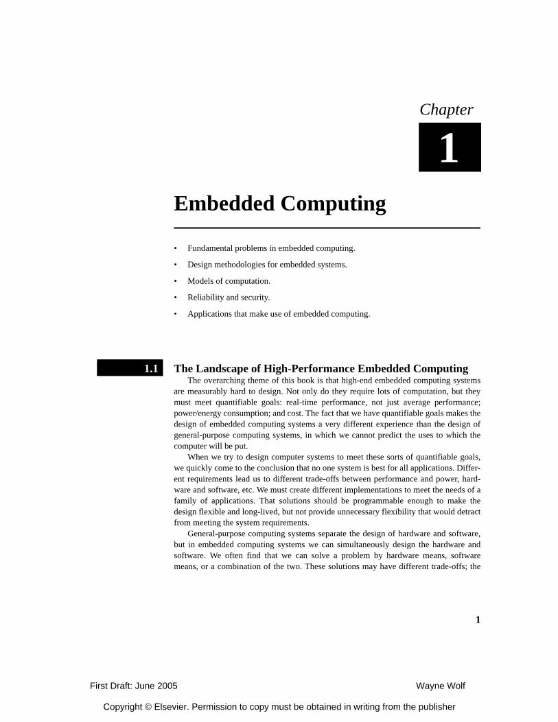
1Embedded Computing 1
• Fundamental problems in embedded computing.
• Design methodologies for embedded systems.
• Models of computation.
• Reliability and security.
• Applications that make use of embedded computing.
The Landscape of High-Performance Embedded ComputingThe overarching theme of this book is that high-end embedded computing systems
are measurably hard to design. Not only do they require lots of computation, but theymust meet quantifiable goals: real-time performance, not just average performance;power/energy consumption; and cost. The fact that we have quantifiable goals makes thedesign of embedded computing systems a very different experience than the design ofgeneral-purpose computing systems, in which we cannot predict the uses to which thecomputer will be put.
When we try to design computer systems to meet these sorts of quantifiable goals,we quickly come to the conclusion that no one system is best for all applications. Differ-ent requirements lead us to different trade-offs between performance and power, hard-ware and software, etc. We must create different implementations to meet the needs of afamily of applications. That solutions should be programmable enough to make thedesign flexible and long-lived, but not provide unnecessary flexibility that would detractfrom meeting the system requirements.
General-purpose computing systems separate the design of hardware and software,but in embedded computing systems we can simultaneously design the hardware andsoftware. We often find that we can solve a problem by hardware means, softwaremeans, or a combination of the two. These solutions may have different trade-offs; the
1.1
First Draft: June 2005 Wayne Wolf
Copyright © Elsevier. Permission to copy must be obtained in writing from the publisher
2 Chapter 1 Embedded Computing
larger design space afforded by joint hardware/software design allows us to find bettersolutions to design problems.
architectures, algorithms, applications
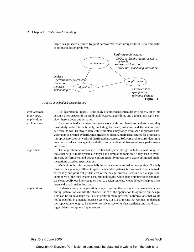
As illustrated in Figure 1-1, the study of embedded system design properly takes intoaccount three aspects of the field: architectures, algorithms, and applications. Let’s con-sider these aspects one at a time.
architectures Because embedded system designers work with both hardware and software, theymust study architectures broadly, including hardware, software, and the relationshipsbetween the two. Hardware architecture problems may range from special-purpose hard-ware units as created by hardware/software co-design, microarchitectures for processors,multiprocessors, or networks of distributed processors. Software architectures determinehow we can take advantage of parallelism and non-determinism to improve performanceand lower cost.
algorithms The algorithmic component of embedded system design includes a wide range oftools that help us build systems. Analysis and simulation tools are widely used to evalu-ate cost, performance, and power consumption. Synthesis tools create optimized imple-mentations based on specifications.
Methodologies play an especially important role in embedded computing. Not onlymust we design many different types of embedded systems, but we want to be able to doso reliably and predictably. The cost of the design process itself is often a significantcomponent of the total system cost. Methodologies, which may combine tools and man-ual steps, codify our knowledge on how to design systems. Methodologies help us makelarge and small design decisions.
applications Understanding your application is key to getting the most out of an embedded com-puting system. We can use the characteristics of the application to optimize our design.This can be an advantage that lets us perform many powerful optimizations that wouldnot be possible in a general-purpose system. But it also means that we must understandthe application enough to be able to take advantage of its characteristics and avoid creat-ing problems for system implementers.
Figure 1-1Aspects of embedded system design.
applications
architectures
algorithms
hardware architectures CPUs, co-design, multiprocessors
software architectures processes, scheduling, allocation
analysis performance, power, costsimulationsynthesismethodologies characteristics
specificationsreference designs
,networks
First Draft: June 2005 Wayne Wolf
Copyright © Elsevier. Permission to copy must be obtained in writing from the publisher
1.1 3
embedded computing is multidisciplinary
Embedded computing makes use of several related disciplines. Two core disciplinesare real-time computing and hardware/software co-design. The study of real-time sys-tems predates the emergence of embedded computing as a discipline. Real-time systemstakes a software-oriented view of how to design computers that complete computationsin a timely fashion. The scheduling techniques developed by the real-time systems com-munity stand at the core of the body of techniques used to design embedded systems.Hardware/software co-design emerged as a field at the dawn of the modern era ofembedded computing. Co-design takes a holistic view of the hardware and software usedto perform deadline-oriented computations.
Embedded computing also takes advantage of many basic disciplines in computerengineering and computer science:
• Low power design started off as primarily hardware-oriented but now encompassesboth software and hardware techniques.
• Programming languages and compilers have brought embedded system designerstools such as Java and highly-optimized code generators.
• Operating systems provide not only schedulers but also file systems and other facili-ties that are now commonplace in high-performance embedded systems.
• Networks are used to create distributed real-time control systems for vehicles andmany other applications, as well as to create Internet-enabled appliances.
• Security and reliability are an increasingly important aspect of embedded systemdesign. VLSI components are becoming less reliable at extremely fine geometrieswhile reliability requirements become more stringent. Security threats oncerestricted to general-purpose systems now loom over embedded systems as well.
this chapter In the remainder of this chapter, we will cover several topics that will serve as recur-ring themes throughout the book. First, we will look at design methodologies. We willsee how traditional hardware or software methodologies have merged and evolved toserve the needs of embedded system designers. Next, we will consider models of compu-tation, which serve as guides for programming and design analysis. We will then look attwo closely related topics—reliability and security—as they apply to embedded systems.We will then review the basics of some important applications of embedded computingso that we can refer to those algorithms and processes in design examples.
remainder of this book
The rest of this book will proceed roughly bottom-up from simpler components tocomplex systems. Chapters 2 through 4 concentrate on single processor systems:
• Chapter 2 will cover CPUs, including the range of microarchitectures available toembedded system designers, processor performance, and power consumption.
• Chapter 3 will look at programs, including languages and design and how to com-pile efficient executable versions of programs.
• Chapter 4 will study real-time scheduling and operating systems.
First Draft: June 2005 Wayne Wolf
Copyright © Elsevier. Permission to copy must be obtained in writing from the publisher

4 Chapter 1 Embedded Computing
Chapters 5 through 8 concentrate on problems specific to multiprocessors:• Chapter 5 describes methods for hardware/software co-design, which designs
accelerators to complement CPUs. • In Chapter 6 we will introduce a taxonomy of multiprocessor hardware architec-
tures and what sorts of multiprocessor structures are useful in optimizing embed-ded system designs.
• In Chapter 7 we will look at software for multiprocessors. • Chapter 8 moves from closely-coupled multiprocessors to networks; we will
study both hardware and software aspects of networked embedded systems.
Design Methodologies
A design methodology is not simply an abstraction—it must be defined in terms ofavailable tools and resources. The designers of high-performance embedded systemsface many challenges. Some of those challenges include:
• The design space is large and irregular. We do not have adequate synthesis tools formany important steps in the design process. As a result, designers must rely on anal-ysis and simulation for many design phases.
• We can’t afford to simulate everything in extreme detail. Not only do simulationstake time, but the cost of the server farm required to run large simulations is a signif-icant element of overall design cost. In particular, we can’t perform a cycle-accuratesimulation of the entire design for the large data sets that are required to validatelarge applications.
• We need to be able to develop simulators quickly. Simulators must reflect the struc-ture of application-specific designs. System architects need tools to help them con-struct application-specific simulators.
• Software developers for systems-on-chips need to be able to write and evaluate soft-ware before the hardware is done. They need to be able to evaluate not just function-ary but performance and power as well.
System designers need tools to help them quickly and reliably build heterogeneousarchitectures. They need tools to help them integrate several different types of proces-sors. They also need tools to help them build multiprocessors from networks, memories,and processing elements.
1.2
First Draft: June 2005 Wayne Wolf
Copyright © Elsevier. Permission to copy must be obtained in writing from the publisher
1.2 Design Methodologies 5
1.2.1 Basic Design Methodologies
Much of the early writings on design methodologies for computer systems cover soft-ware, but the methodologies for hardware tend to be more concrete since hardwaredesign makes more use of synthesis and simulation tools. An ideal embedded systemsmethodology makes use of the best of both hardware and software traditions.
waterfall and spiral
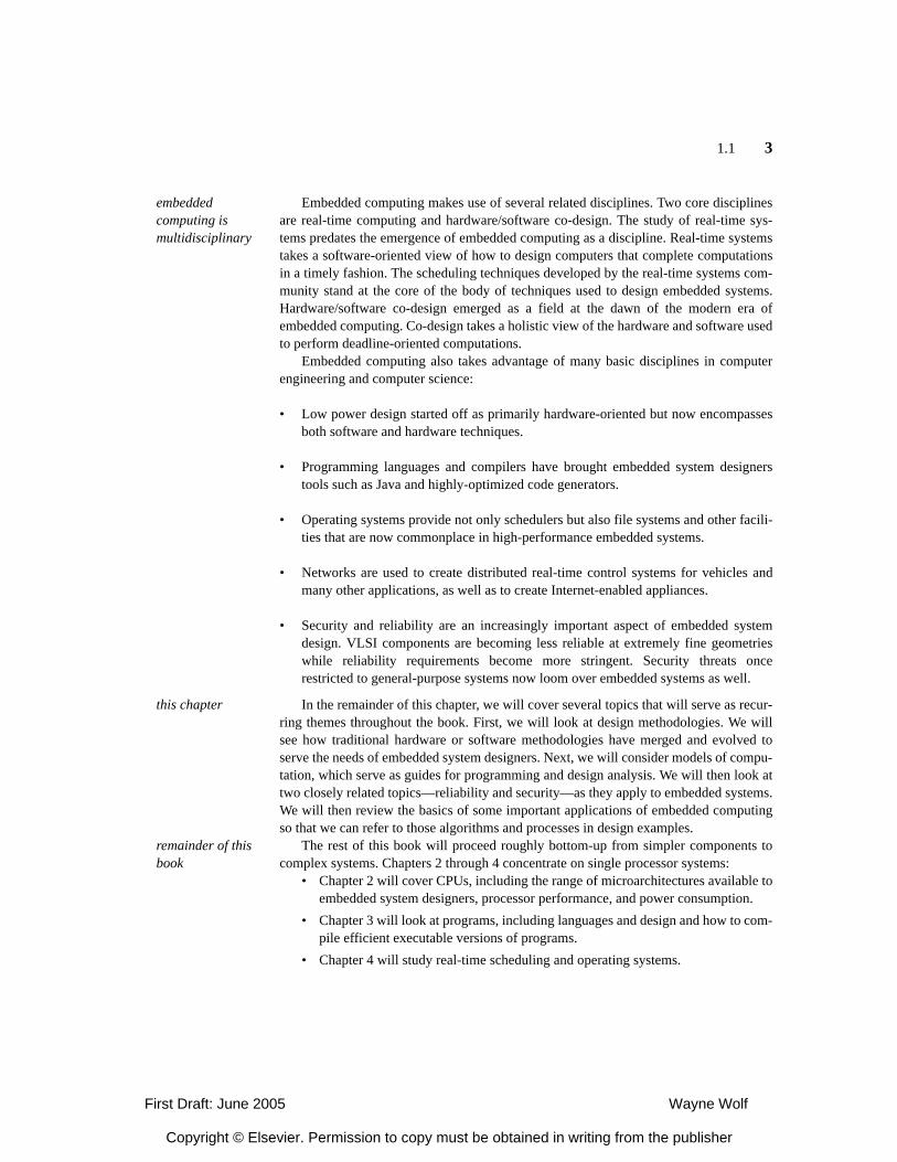
One of the earliest models for software development was the waterfall model illus-trated in Figure 1-2. The waterfall model is divided into five major stages: requirements,specification, architecture, coding, and maintenance. The software is successivelyrefined through these stages, with maintenance including software delivery and follow-on updates and fixes. Most of the information in this methodology flows from the topdown—that is, from more abstract stages to more concrete stages—although some infor-mation could flow back from one stage to the preceding stage to improve the design. Thegeneral flow of design information down the levels of abstraction gives the waterfallmodel its name. The waterfall model was important for codifying the basic steps of soft-ware development, but researchers soon realized that the limited flow of informationfrom detailed design back to improve the more abstract phases was both an unrealisticpicture of software design practices and an undesirable feature of an ideal methodology.In practice, designers can and should use experience from design steps to go back,rethink earlier decisions, and redo some work.
requirements
specification
architecture
coding
maintenance
requirements
architecturecoding prototype
requirements
architecturecoding initialdesign
requirements
architecturecoding refineddesign
waterfall spiral
Figure 1-2Two early models of software development.
First Draft: June 2005 Wayne Wolf
Copyright © Elsevier. Permission to copy must be obtained in writing from the publisher
6 Chapter 1 Embedded Computing
The spiral model, also shown in Figure 1-2, was a reaction to and a refinement ofthe waterfall model. This model envisions software design as an iterative process inwhich several versions of the system, each better than the last, is created. At each phase,designers go through a requirements/architecture/coding cycle. The results of one cycleare used to guide the decisions in the next round of development. Experience from onestage should both help give a better design at the next stage and allow the design team tocreate that improved design more quickly.
hardware design methodologies
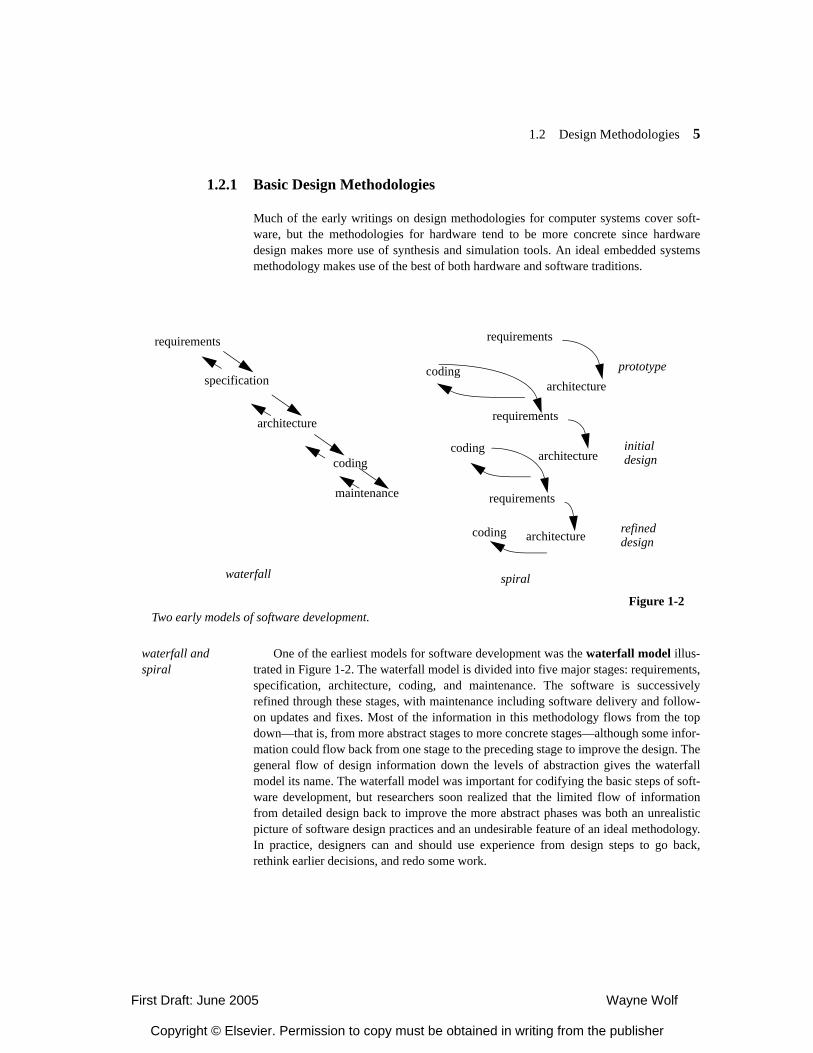
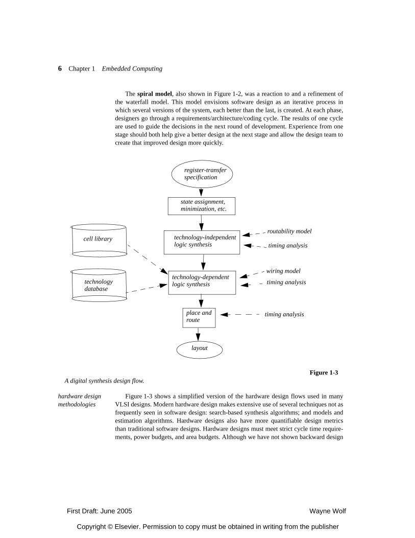
Figure 1-3 shows a simplified version of the hardware design flows used in manyVLSI designs. Modern hardware design makes extensive use of several techniques not asfrequently seen in software design: search-based synthesis algorithms; and models andestimation algorithms. Hardware designs also have more quantifiable design metricsthan traditional software designs. Hardware designs must meet strict cycle time require-ments, power budgets, and area budgets. Although we have not shown backward design
register-transferspecification
state assignment,minimization, etc.
technology-independentcell library
technologydatabase
place androute
layout
logic synthesis
technology-dependentlogic synthesis
Figure 1-3A digital synthesis design flow.
routability model
wiring model
timing analysis
timing analysis
timing analysis
First Draft: June 2005 Wayne Wolf
Copyright © Elsevier. Permission to copy must be obtained in writing from the publisher
1.2 Design Methodologies 7
flow from lower to higher levels of abstraction, most design flows allow such iterativedesign.
Modern hardware synthesis uses many types of models. In Figure 1-3, the celllibrary describes the cells used for logic gates and registers, both concretely in terms oflayout primitives and more abstractly in terms of delay, area, etc. The technology data-base captures data not directly associated with cells, such as wire characteristics. Thesedatabases generally carry static data in the form of tables. Algorithms are also used toevaluate models. For example, several types of wirability models are used to estimate theproperties of the wiring in the layout before that wiring is complete. Timing and powermodels evaluate the performance and power consumption of designs before all thedetails of the design are known; for example, although both timing and power depend onthe exact wiring, wire length estimates can be used to help estimate timing and powerbefore the delay is complete. Good estimators help keep design iterations local. Thetools may search the design space to find a good design, but within a given level ofabstraction and based up on models at that level. Good models combined with effectiveheuristic search can minimize the need for backtracking and throwing out design results.
1.2.2 Embedded Systems Design Flows
Embedded computing systems combine hardware and software components that mustwork closely together. Embedded system designers have evolved design methodologiesthat play into our ability to embody part of the functionality of the system in software.
co-design flows Early researchers in hardware/software co-design emphasized the importance ofconcurrent design. Once the system architecture has been defined, the hardware and soft-ware components can be designed relatively separately. The goal of co-design is to makeappropriate architectural decisions that allow later implementation phases to be carriedout separately. Good architectural decisions, because they must satisfy hard metrics likereal-time performance and power consumption, require appropriate analysis methods.
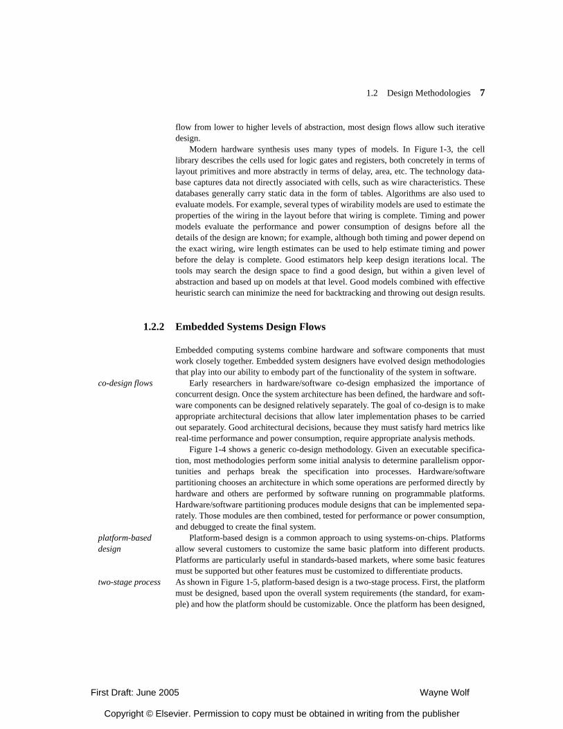
Figure 1-4 shows a generic co-design methodology. Given an executable specifica-tion, most methodologies perform some initial analysis to determine parallelism oppor-tunities and perhaps break the specification into processes. Hardware/softwarepartitioning chooses an architecture in which some operations are performed directly byhardware and others are performed by software running on programmable platforms.Hardware/software partitioning produces module designs that can be implemented sepa-rately. Those modules are then combined, tested for performance or power consumption,and debugged to create the final system.
platform-based design
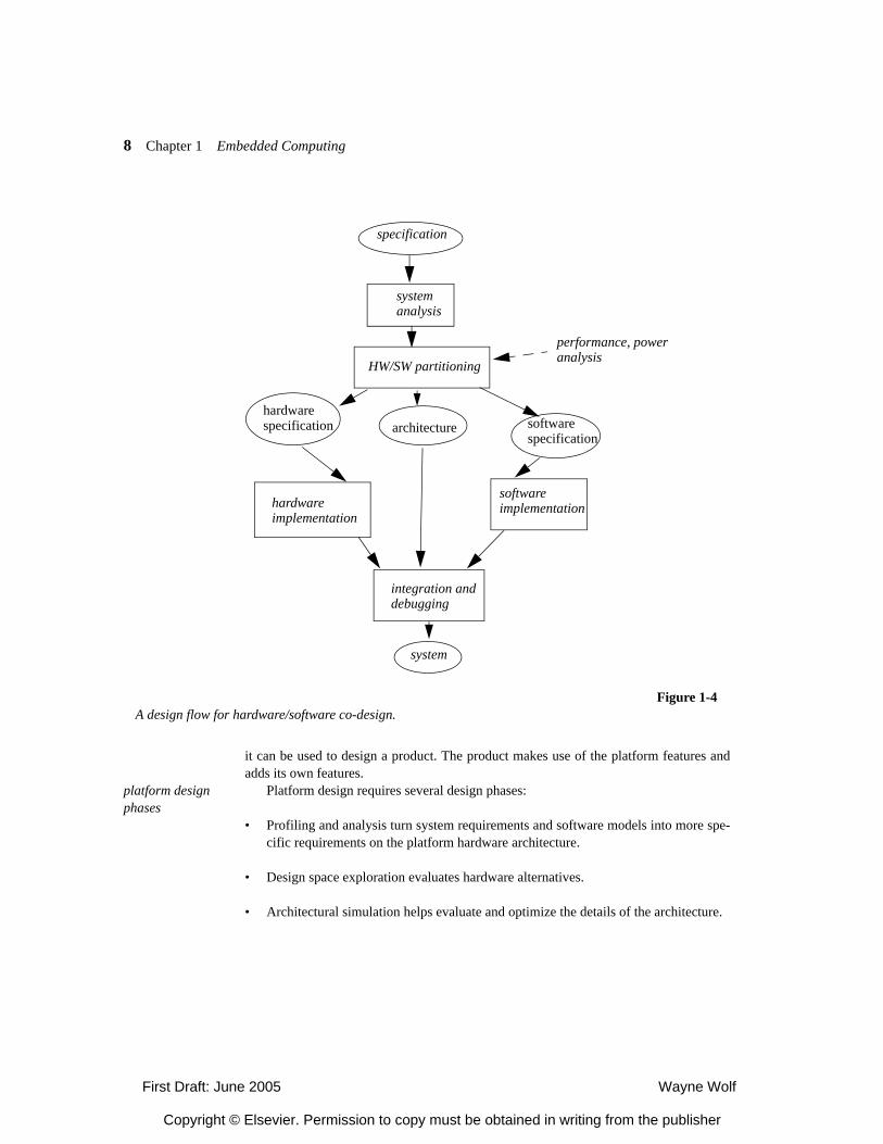
Platform-based design is a common approach to using systems-on-chips. Platformsallow several customers to customize the same basic platform into different products.Platforms are particularly useful in standards-based markets, where some basic featuresmust be supported but other features must be customized to differentiate products.
two-stage process As shown in Figure 1-5, platform-based design is a two-stage process. First, the platformmust be designed, based upon the overall system requirements (the standard, for exam-ple) and how the platform should be customizable. Once the platform has been designed,
First Draft: June 2005 Wayne Wolf
Copyright © Elsevier. Permission to copy must be obtained in writing from the publisher
8 Chapter 1 Embedded Computing
it can be used to design a product. The product makes use of the platform features andadds its own features.
platform design phases
Platform design requires several design phases:
• Profiling and analysis turn system requirements and software models into more spe-cific requirements on the platform hardware architecture.
• Design space exploration evaluates hardware alternatives.
• Architectural simulation helps evaluate and optimize the details of the architecture.
Figure 1-4A design flow for hardware/software co-design.
specification
systemanalysis
HW/SW partitioning
hardwareimplementation
softwareimplementation
integration anddebugging
system
performance, poweranalysis
architecturehardwarespecification software
specification
First Draft: June 2005 Wayne Wolf
Copyright © Elsevier. Permission to copy must be obtained in writing from the publisher
1.2 Design Methodologies 9
• Base software—hardware abstraction layers, operating system ports, communica-tion, application libraries, debugging—must be developed for the platform.
programming platforms
Platform use is challenging in part because the platform requires a custom program-ming environment. Programmers are used to rich development environments for stan-dard platforms. Those environments provide a number of tools—compilers, editors,debuggers, simulators—in a single graphical user interface. However, rich programmingenvironments are typically available for uniprocessors. Multiprocessors are harder toprogram and heterogeneous multiprocessors are harder than homogeneous multiproces-sors. The platform developers must provide tools that allow software developers to usethe platform. Some of these tools come from the component CPUs but other tools mustbe developed from scratch. Debugging is particularly important and difficult, sincedebugging access is hardware-dependent. Interprocess communication is also challeng-ing but is a critical tool for application developers.
1.2.3 Standards-Based Design Methodologies
Many high-performance embedded computing systems implement standards. Multi-media, communications, and networking all provide standards for various capabilities.One product may even implement several different standards. In this section we willconsider the effects that the standards have on embedded system design methodologies[Wol04].
Figure 1-5Platform-based design.
systemrequirements
customizationneeds
platformdesign
platform
productrequirements
platform use
product
First Draft: June 2005 Wayne Wolf
Copyright © Elsevier. Permission to copy must be obtained in writing from the publisher
10 Chapter 1 Embedded Computing
pros and cons of standards
On the one hand, standards enable products and in particular systems-on-chips. Stan-dards create large markets for particular types of functions: they allow devices to inter-operate and they reassure customers that the device provides the required functions.Large markets help justify any system design project, but they are particularly importantin system-on-chip design. In order to cover the costs of SoC design and manufacturing,several million of the chips must be sold in many cases. Such large markets are generallycreated by standards.
On the other hand, the fact that the standard exists means that the chip designershave much less control over the specification of what they need to design. Standardsdefine complex behavior that must be adhered to. As a result, some features of the archi-tecture will be dictated by the standard.
Most standards do provide for improvements. Many standards define that certainoperations must be performed, but they do not specify how they may be performed. Theimplementer can choose a method based upon performance, power, cost, quality, or easeof implementation. For example, video compression standards define basic parametersof motion estimation but not what motion estimation algorithm should be performed.
The intellectual property and effort required to implement a standard goes into dif-ferent parts of the system than would be the case for a blank-sheet design. Algorithmdesign effort goes into unspecified parts of the standard and parts of the system that liebeyond the standard. For example, cell phones must adhere to communication standardsbut are free to design many aspects of their user interfaces.
Standards are often complex, and standards in a given field often become more com-plex over time. As a field evolves, practitioners learn more about how to do a better joband tend to build that knowledge into the standard. While these improvements may leadto higher quality systems, they also make the system implementation larger.
reference implementations
Standards bodies typically provide a reference implementation. This is an execut-able program that conforms to the standard. It is often written in C, but may be written inJava or some other language. The reference implementation is first used to aid the stan-dard developers. It is then distributed to implementers of the specification. (The refer-ence implementation may be available free of charge, but in many cases an implementermust pay a license fee to the standards body to build a system that conforms to the spec-ification. The license fee goes primarily to patent holders whose inventions are usedwithin the standard.) There may be several reference implementations if multiple groupsexperiment with the standard and release their results.
The reference implementation is something of a mixed blessing for system design-ers. On the one hand, the reference implementation saves the system designers a greatdeal of time. On the other hand, it comes with some liabilities. Of course, learning some-one else’s code is always time-consuming. Furthermore, the code generally cannot beused as-is. Reference implementations are typically written to run on a large workstationwith infinite memory; it is generally not designed to operate in real time. The code mustoften be restructured in many ways: eliminating features that will not be implemented;replacing heap allocation with custom memory management; improving cache utiliza-tion; function inlining; and many other tasks.
design tasks The implementer of a standard must perform several design tasks:
First Draft: June 2005 Wayne Wolf
Copyright © Elsevier. Permission to copy must be obtained in writing from the publisher
1.2 Design Methodologies 11
• The unspecified parts of the implementation must be designed.
• Parts of the system that are not specified by the standard (user interface, for exam-ple), must be designed.
• An initial round of platform-independent optimization must be used to improve thechosen reference implementation.
• The reference implementation and other code must be profiled and analyzed.
• The hardware platform must be designed based upon initial characterization.
• The system software must be further optimized to better match the platform.
• The platform itself must be further optimized based upon additional profiling.
• The platform and software must be verified for conformance to the standard as wellas non-functional parameters such as performance and energy consumption.
The next example introduces the Advanced Video Coding standard.
Application Example 1-1
AVC/H.264
The latest generation of video compression standards is known by several names. It isofficially part 10 of the MPEG-4 standard, known as Advanced Video Coding (AVC).However, the MPEG group joined forces with the H.26x group, so it is also known asH.264.
The MPEG family of standards is primarily oriented toward broadcast, in which thetransmitter is more complex in favor of cheaper receivers. The H.26x family of stan-dards, in contrast, has traditionally targeted videoconferencing, in which systems mustboth transmit and receive, giving little incentive to trade transmitter complexity forreceiver complexity.
The H.264 standard provides many features that give improved picture quality andcompression ratio. H.264 codecs typically generate encoded streams that are half the sizeof MPEG-2 encodings. For example, the H.264 standard allows multiple referenceframes, so that motion estimation can use pixels from several frames to handle occlu-sion. This is an example of a feature that improves quality at the cost of increasedreceiver complexity.
The reference implementation for H.264 is over 700,000 lines of C code. This refer-ence implementation uses only fairly simple algorithm for some unspecified parts of the
First Draft: June 2005 Wayne Wolf
Copyright © Elsevier. Permission to copy must be obtained in writing from the publisher
12 Chapter 1 Embedded Computing
standard, such as motion estimation. However, it implements both video coding anddecoding and it does so for the full range of display sizes supported by the standard,ranging from QCIF to HDTV.
1.2.4 A Methodology of Methodologies
The design of high-performance embedded systems is not described well by simplemethodologies. Given that these systems implement specifications that are millions oflines long, it should not be surprising that we have to use many different types of designprocesses to build complex embedded systems.
Methodologies that we use in embedded system design include:
• software performance analysis Executable specifications must be analyzed todetermine how much computing horsepower is needed and what types of operationsneed to be performed.
• architectural optimization Cycle-accurate simulation and other architectural meth-ods can be used to optimize systems.
• hardware/software co-design Co-design helps us create efficient heterogeneousarchitectures.
• network design Whether in distributed embedded systems or systems-on-chips, net-works must provide the necessary bandwidth at reasonable energy levels.
• software testing Software must be evaluated for functional correctness and perfor-mance on the target platform.
• software tool generation Tools to program the system must be generated from thehardware and software architectures.
1.2.5 Joint Algorithm and Architecture Development
Embedded systems architectures may be designed along with the algorithms they willexecute. This is true even in standards-based systems, since standards generally allowfor algorithmic enhancements. Joint algorithm/architecture development creates somespecial challenges for system designers.
Algorithm designers need estimates and models to help them tailor the algorithm tothe architecture. Even though the architecture is not complete, the hardware architects
First Draft: June 2005 Wayne Wolf
Copyright © Elsevier. Permission to copy must be obtained in writing from the publisher
1.3 Models of Computation 13
should be able to supply estimates of performance and power consumption. Theseshould be useful for simulators that take models of the underlying architecture.
Algorithm designers also need to be able to develop software. This requires func-tional simulators that run as fast as possible. If hardware were available, algorithmdesigners could run code at native speeds. Functional simulators can provide adequatelevels of performance for many applications even if they don’t run at hardware speeds.Fast turnaround of compilation and simulation is very important to successful softwaredevelopment.
Models of Computation
A model of computation defines the basic capabilities of an abstract computer. In theearly days of computer science, models of computation helped researchers understandthe basic capabilities of computers. In embedded computing, models of computationhelp us understand how to correctly and easily program complex systems. In this sectionwe will consider several models of computation and the relationships between them. Thestudy of models of computation have influenced the way real embedded systems aredesigned; we will balance the theory in this section with mentions of how some of thesetheoretical techniques have influenced embedded software design.
1.3.1 Why Study Models of Computation?
expressiveness Models of computation help us understand the expressiveness of various program-ming languages. Expressiveness has several different aspects. On the one hand, we canprove that some models are more expressive than others---that some styles of computingcan do some things that other styles can’t. But expressiveness also has implications forprogramming style that are at least as important for embedded system designers. Twolanguages that rae both formally equally expressive may be good at very different typesof applications. For example, control and data are often programmed in very differentways; a language may express one only with difficulty but the other easily.
language styles Experienced programmers can think of several types of expressiveness that can beuseful when writing programs:
• control vs. data This is one of the most basic dichotomies in programming.Although control and data are formally equivalent. we tend to think about them verydifferently. Many programming languages have been developed for control-intensiveapplications like protocol design. Similarly, many other programming languageshave been designed for data-intensive applications like signal processing.
1.3
First Draft: June 2005 Wayne Wolf
Copyright © Elsevier. Permission to copy must be obtained in writing from the publisher
14 Chapter 1 Embedded Computing
• sequential vs. parallel This is another basic theme in computer programming. Manylanguages have been developed to make it easy to describe parallel programs in away that is both intuitive and formally verifiable. However, programmers still feelcomfortable with sequential programming when they can get away with it.
• communication The nature of communication between units in a program is relatedto the way that parallelism is described. Sequential languages communicate by pass-ing control. Various communication mechanisms have been developed for differentapplications. These may describe control-oriented vs. data-oriented communication.They may also embody different methods of buffering communicated data.
The astute reader will note that we aren’t concerned here about some traditional pro-gramming language issues such as modularity. While modularity and maintainability areimportant, they are not unique to embedded computing. Some of the other aspects of lan-guages that we mention are more central to embedded systems that must implement sev-eral different styles of computation so that they work together smoothly.
interoperability Expressiveness may lead us to use more than one programming language to build asystem.—we call these systems heterogeneously programmed. When we mix pro-gramming languages, we must satisfy the extra burden of correctly designing the com-munication between modules of different programming languages. Within a givenlanguage, the language system often helps us verify certain basic operations and it ismuch easier to think about how the program works. When we mix and match multiplelanguages, it is much more difficult for us to convince ourselves that the programs willwork together properly. Understanding the model under which each programming lan-guage works and the conditions under which they can reliably communicate is a criticalstep in the design of heterogeneously programmed systems.
1.3.2 Finite vs. Infinite State
finite vs. infinite state
The amount of state that can be described by a model is one of the most fundamentalaspects of any model of computation. Early work on computability emphasized the capa-bilities of finite-state vs. infinite-state machines; infinite state was generally consideredto be good because it showed that the machine was more capable. However, finite-statemodels are much easier to verify in both theory and practice. As a result, finite-state pro-gramming models have an important place in embedded computing.
finite-state machine
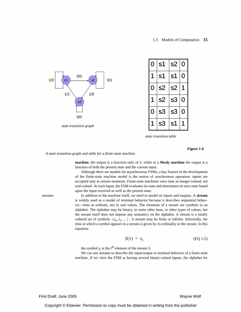
Finite-state machines (FSMs) are well understood to both software and hardwaredesigners. An example is shown in Figure 1-6. An FSM is typically defined as
(EQ 1-1)
where I and O are the inputs and outputs of the machine, S is its current state, and ∆and Τ are the states and transitions respectively of the state transition graph. In a Moore
M I O S ∆ T, , , ,{ }=
First Draft: June 2005 Wayne Wolf
Copyright © Elsevier. Permission to copy must be obtained in writing from the publisher
1.3 Models of Computation 15
machine, the output is a function only of S, while in a Mealy machine the output is afunction of both the present state and the current input.
Although there are models for asynchronous FSMs, a key feature in the developmentof the finite-state machine model is the notion of synchronous operation: inputs areaccepted only at certain moments. Finite-state machines view time as integer-valued, notreal-valued. At each input, the FSM evaluates its state and determines its next state basedupon the input received as well as the present state.
streams In addition to the machine itself, we need to model its inputs and outputs. A streamis widely used as a model of terminal behavior because it describes sequential behav-ior—time as ordinals, not in real values. The elements of a stream are symbols in analphabet. The alphabet may be binary, in some other base, or other types of values, butthe stream itself does not impose any semantics on the alphabet. A stream is a totallyordered set of symbols . A stream may be finite or infinite. Informally, thetime at which a symbol appears in a stream is given by its ordinality in the stream. In thisequation:
(EQ 1-2)
the symbol st is the tth element of the stream S.We can use streams to describe the input/output or terminal behavior of a finite-state
machine. If we view the FSM as having several binary-valued inputs, the alphabet for
Figure 1-6A state transition graph and table for a finite-state machine.
s3
s1 s20/0
0/1
1/0
0/0
1/1
1/0
state transition graph 1s1s31
0s3s30
0s3s21
1s2s20
0s1s11
0s2s10
1s1s31
0s3s30
0s3s21
1s2s20
0s1s11
0s2s10
state transition table
s0 s1 …, ,⟨ ⟩
S t( ) st=
First Draft: June 2005 Wayne Wolf
Copyright © Elsevier. Permission to copy must be obtained in writing from the publisher
16 Chapter 1 Embedded Computing
the input stream will be binary numbers; in some cases it is useful to think of the inputsas forming a group whose values are determined by a single symbol that defines thestates of all the inputs. Similar thinking can be applied to the outputs. The behavior ofthe inputs is then described as one or more streams, depending on the alphabet used.Similarly, the output behavior is described as one or more streams. At time i, the FSMconsumes a symbol on each of its input streams and produces a symbol on each of itsoutput streams. The mapping from inputs to outputs is determined by the state transitiongraph and the machine’s internal state. From the terminal view, the FSM is synchronousbecause the consumption of inputs and generation of outputs is coordinated.
verification and finite state
Although synchronous finite-state machines may be most familiar to hardwaredesigners, synchronous behavior is a growing trend in the design of languages forembedded computing. Finite-state machines make interesting models for softwarebecause they can be more easily verified than infinite-state machines. Because an FSMhas a finite number of states, we can visit all the states and exercise all the transitions ina finite amount of time. If a system has infinite state, we cannot visit all its states in finitetime. Although it may seem impractical to walk through all the states of an FSM in prac-tice, research over the past 20 years has led us to very efficient algorithms for exploringlarge state spaces. The ordered Boolean decision diagram (OBDD) [cite Randy Bryanthere] can be used to describe combinational Boolean functions. Techniques have beendeveloped to describe state spaces in terms of OBDDs such that properties of those statespaces can be efficiently checked in many cases. OBDDs do not take away the basic NP-completeness of combinational and state space search problems; in some cases theOBDDs can become very large and slow to evaluate. But in many cases they run veryfast and even in pathological cases can be faster than competing methods.
OBDDs allow us to perform many checks that are useful tests of the correctness ofpractical systems:
• product machines It is often easier to express complex functions as systems of com-municating machines. However, hidden bugs may lurk in the communicationbetween those components. Building the product of the communicating machines isthe first step in many correctness checks.
• reachability Many bugs manifest themselves as inabilities to reach certain states inthe machine. In some cases, unreachable states may simply describe useless butunimportant behavior. In other cases, unreachable states may signal a missing featurein the system.
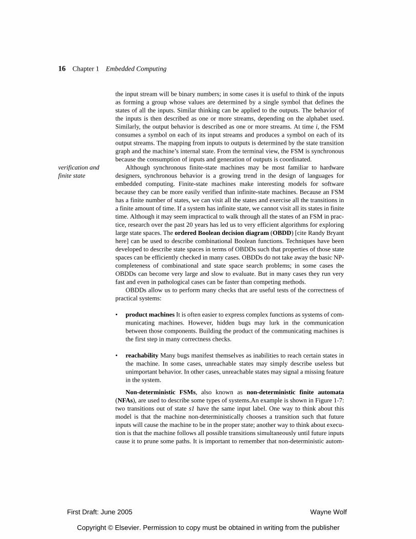
Non-deterministic FSMs, also known as non-deterministic finite automata(NFAs), are used to describe some types of systems.An example is shown in Figure 1-7:two transitions out of state s1 have the same input label. One way to think about thismodel is that the machine non-deterministically chooses a transition such that futureinputs will cause the machine to be in the proper state; another way to think about execu-tion is that the machine follows all possible transitions simultaneously until future inputscause it to prune some paths. It is important to remember that non-deterministic autom-
First Draft: June 2005 Wayne Wolf
Copyright © Elsevier. Permission to copy must be obtained in writing from the publisher
1.3 Models of Computation 17
ata are not formally more expressive than deterministic FSMs. An algorithm can trans-form any NFA into an equivalent deterministic machine. But NFAs can be exponentiallysmaller than its equivalent deterministic machine. This is a simple but clear example ofthe stylistic aspect of expressiveness.
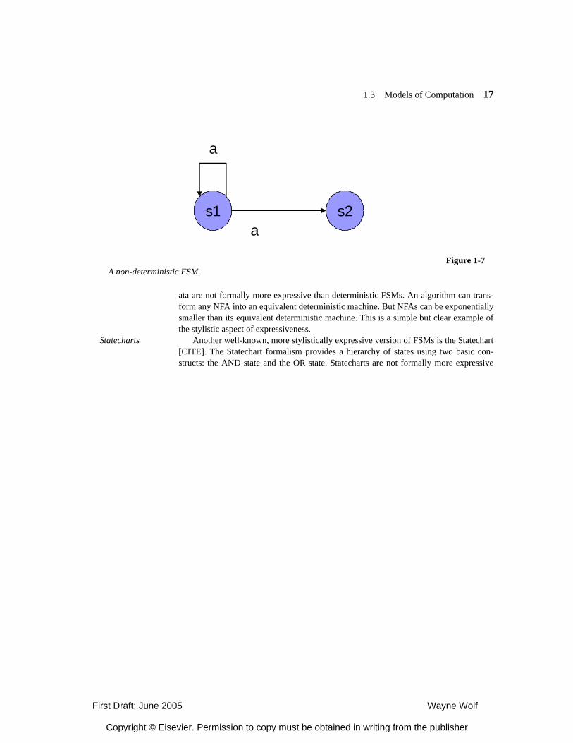
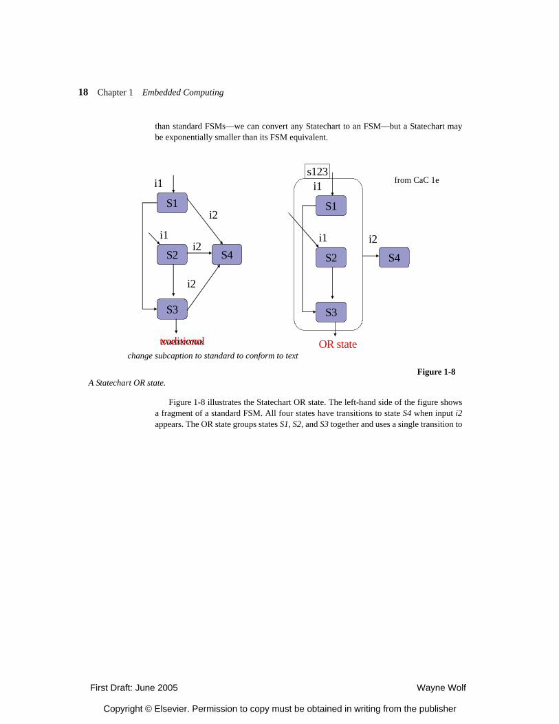
Statecharts Another well-known, more stylistically expressive version of FSMs is the Statechart[CITE]. The Statechart formalism provides a hierarchy of states using two basic con-structs: the AND state and the OR state. Statecharts are not formally more expressive
Figure 1-7A non-deterministic FSM.
s1 s2a
a
First Draft: June 2005 Wayne Wolf
Copyright © Elsevier. Permission to copy must be obtained in writing from the publisher
18 Chapter 1 Embedded Computing
than standard FSMs—we can convert any Statechart to an FSM—but a Statechart maybe exponentially smaller than its FSM equivalent.
Figure 1-8 illustrates the Statechart OR state. The left-hand side of the figure showsa fragment of a standard FSM. All four states have transitions to state S4 when input i2appears. The OR state groups states S1, S2, and S3 together and uses a single transition to
Figure 1-8A Statechart OR state.
S1
S2
S3
S4
i1
i1
i2
i2
i2
traditional
S1
S2
S3
S4
i1
i1 i2
OR state
s123from CaC 1e
xxxxxxxxxxx
change subcaption to standard to conform to text
First Draft: June 2005 Wayne Wolf
Copyright © Elsevier. Permission to copy must be obtained in writing from the publisher
1.3 Models of Computation 19
specify that input i2 causes a transition from any state in the OR state (named s123) tostate S4.
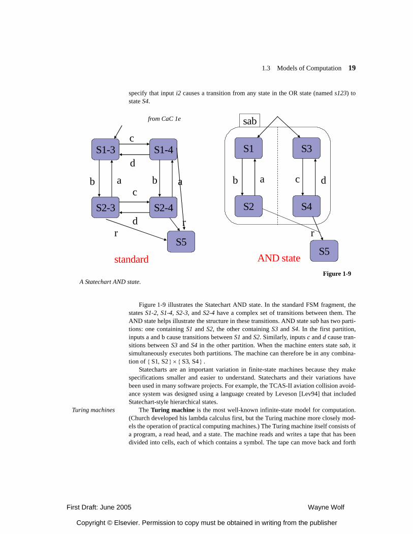
Figure 1-9 illustrates the Statechart AND state. In the standard FSM fragment, thestates S1-2, S1-4, S2-3, and S2-4 have a complex set of transitions between them. TheAND state helps illustrate the structure in these transitions. AND state sab has two parti-tions: one containing S1 and S2, the other containing S3 and S4. In the first partition,inputs a and b cause transitions between S1 and S2. Similarly, inputs c and d cause tran-sitions between S3 and S4 in the other partition. When the machine enters state sab, itsimultaneously executes both partitions. The machine can therefore be in any combina-tion of .
Statecharts are an important variation in finite-state machines because they makespecifications smaller and easier to understand. Statecharts and their variations havebeen used in many software projects. For example, the TCAS-II aviation collision avoid-ance system was designed using a language created by Leveson [Lev94] that includedStatechart-style hierarchical states.
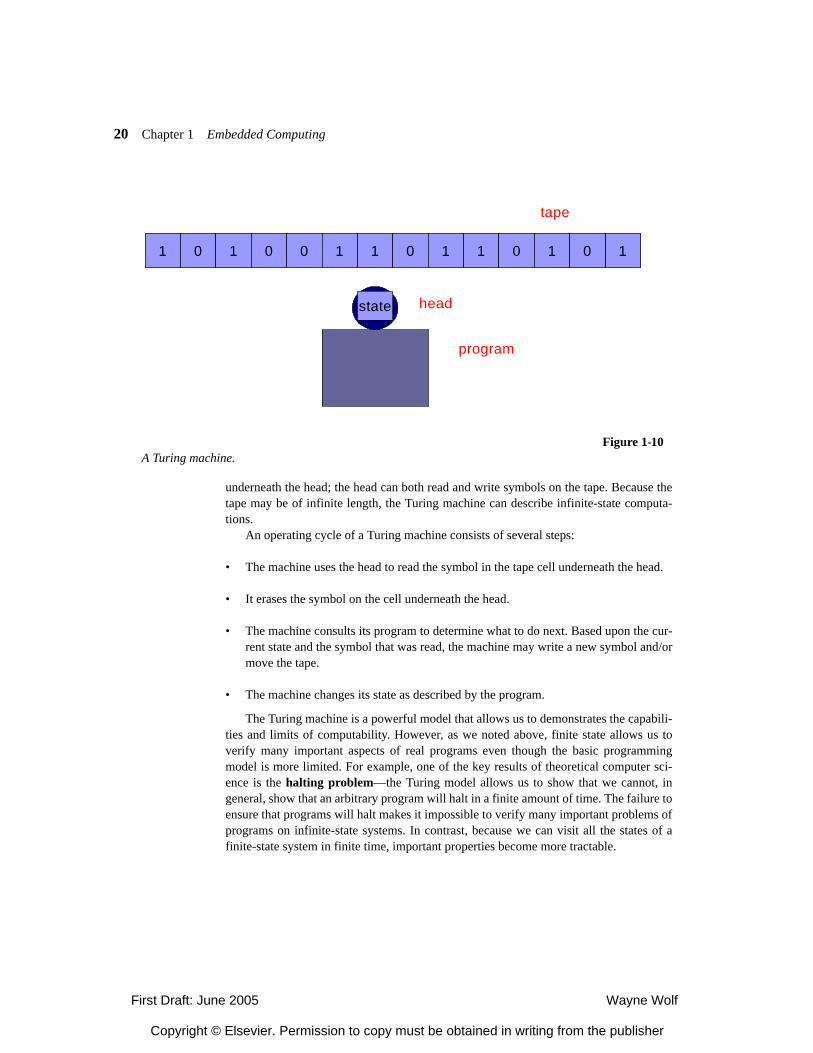
Turing machines The Turing machine is the most well-known infinite-state model for computation.(Church developed his lambda calculus first, but the Turing machine more closely mod-els the operation of practical computing machines.) The Turing machine itself consists ofa program, a read head, and a state. The machine reads and writes a tape that has beendivided into cells, each of which contains a symbol. The tape can move back and forth
Figure 1-9A Statechart AND state.
S1-3 S1-4
S2-3 S2-4
S5standard
c
db a
r
c
d
b a
S1 S3
S2 S4
S5AND state
c d
r
b a
sab
r
from CaC 1e
S1 S2,{ } S3 S4,{ }×
First Draft: June 2005 Wayne Wolf
Copyright © Elsevier. Permission to copy must be obtained in writing from the publisher
20 Chapter 1 Embedded Computing
underneath the head; the head can both read and write symbols on the tape. Because thetape may be of infinite length, the Turing machine can describe infinite-state computa-tions.
An operating cycle of a Turing machine consists of several steps:
• The machine uses the head to read the symbol in the tape cell underneath the head.
• It erases the symbol on the cell underneath the head.
• The machine consults its program to determine what to do next. Based upon the cur-rent state and the symbol that was read, the machine may write a new symbol and/ormove the tape.
• The machine changes its state as described by the program.
The Turing machine is a powerful model that allows us to demonstrates the capabili-ties and limits of computability. However, as we noted above, finite state allows us toverify many important aspects of real programs even though the basic programmingmodel is more limited. For example, one of the key results of theoretical computer sci-ence is the halting problem—the Turing model allows us to show that we cannot, ingeneral, show that an arbitrary program will halt in a finite amount of time. The failure toensure that programs will halt makes it impossible to verify many important problems ofprograms on infinite-state systems. In contrast, because we can visit all the states of afinite-state system in finite time, important properties become more tractable.
Figure 1-10A Turing machine.
1 0 1 0 10 1 0 1 1 0 11 01 0 1 0 10 1 0 1 1 0 11 0
program
head
tape
state
First Draft: June 2005 Wayne Wolf
Copyright © Elsevier. Permission to copy must be obtained in writing from the publisher
1.3 Models of Computation 21
1.3.3 Parallelism and Communication
Parallelism is a fundamental concept in computer science and of great practical impor-tance in embedded systems. Many embedded systems perform many tasks simulta-neously. The real parallelism embodied in the hardware must be matched by apparentparallelism in the programs.
parallelism and architecture
We need to capture parallelism during the early stages of design so that we can use itto optimize our design. Parallel algorithms describe time as partially ordered—the exactsequence of operations is not determined up front. As we bind operations to the architec-ture, we move the description toward a totally ordered description (although some oper-ations may be left partially ordered to be managed by the operating system). Differentchoices for ordering require different amounts of hardware resources, affecting cost andpower consumption.
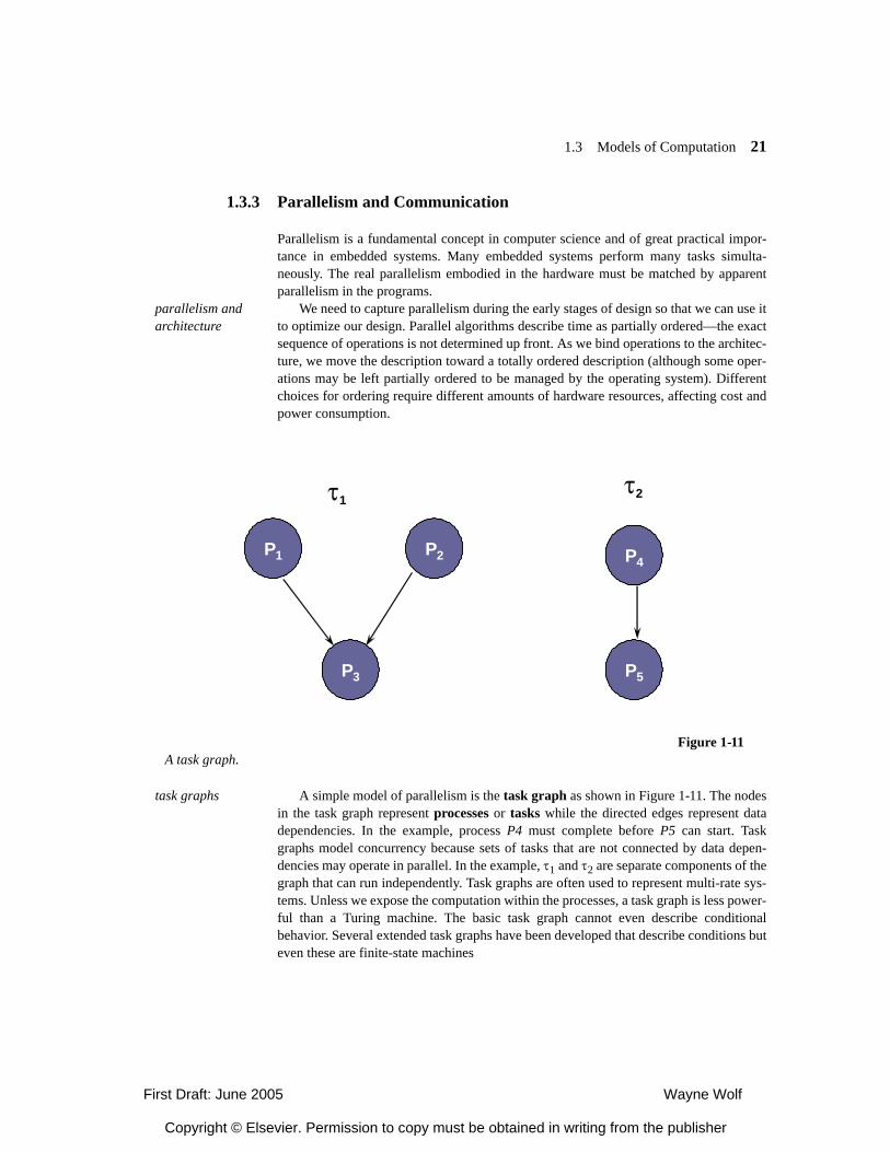
task graphs A simple model of parallelism is the task graph as shown in Figure 1-11. The nodesin the task graph represent processes or tasks while the directed edges represent datadependencies. In the example, process P4 must complete before P5 can start. Taskgraphs model concurrency because sets of tasks that are not connected by data depen-dencies may operate in parallel. In the example, τ1 and τ2 are separate components of thegraph that can run independently. Task graphs are often used to represent multi-rate sys-tems. Unless we expose the computation within the processes, a task graph is less power-ful than a Turing machine. The basic task graph cannot even describe conditionalbehavior. Several extended task graphs have been developed that describe conditions buteven these are finite-state machines
Figure 1-11A task graph.
τ1τ2
P1 P2
P3
P4
P5
First Draft: June 2005 Wayne Wolf
Copyright © Elsevier. Permission to copy must be obtained in writing from the publisher
22 Chapter 1 Embedded Computing
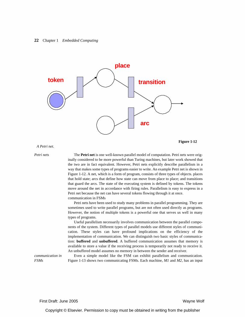
Petri nets The Petri net is one well-known parallel model of computation. Petri nets were orig-inally considered to be more powerful than Turing machines, but later work showed thatthe two are in fact equivalent. However, Petri nets explicitly describe parallelism in away that makes some types of programs easier to write. An example Petri net is shown inFigure 1-12. A net, which is a form of program, consists of three types of objects. placesthat hold state; arcs that define how state can move from place to place; and transitionsthat guard the arcs. The state of the executing system is defined by tokens. The tokensmove around the net in accordance with firing rules. Parallelism is easy to express in aPetri net because the net can have several tokens flowing through it at once.communication in FSMs
Petri nets have been used to study many problems in parallel programming. They aresometimes used to write parallel programs, but are not often used directly as programs.However, the notion of multiple tokens is a powerful one that serves us well in manytypes of programs.
Useful parallelism necessarily involves communication between the parallel compo-nents of the system. Different types of parallel models use different styles of communi-cation. These styles can have profound implications on the efficiency of theimplementation of communication. We can distinguish two basic styles of communica-tion: buffered and unbuffered. A buffered communication assumes that memory isavailable to store a value if the receiving process is temporarily not ready to receive it.An unbuffered model assumes no memory in between the sender and receiver.
communication in FSMs
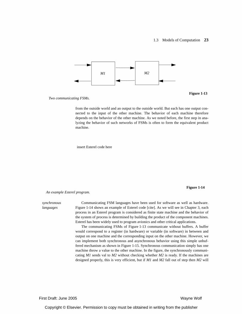
Even a simple model like the FSM can exhibit parallelism and communication.Figure 1-13 shows two communicating FSMs. Each machine, M1 and M2, has an input
Figure 1-12A Petri net.
place
arc
token transition
First Draft: June 2005 Wayne Wolf
Copyright © Elsevier. Permission to copy must be obtained in writing from the publisher
1.3 Models of Computation 23
from the outside world and an output to the outside world. But each has one output con-nected to the input of the other machine. The behavior of each machine thereforedepends on the behavior of the other machine. As we noted before, the first step in ana-lyzing the behavior of such networks of FSMs is often to form the equivalent productmachine.
synchronous languages
Communicating FSM languages have been used for software as well as hardware.Figure 1-14 shows an example of Esterel code [cite]. As we will see in Chapter 3, eachprocess in an Esterel program is considered as finite state machine and the behavior ofthe system of process is determined by building the product of the component machines.Esterel has been widely used to program avionics and other critical applications.
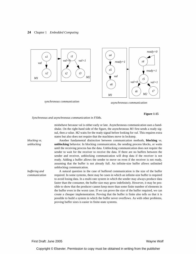
The communicating FSMs of Figure 1-13 communicate without buffers. A bufferwould correspond to a register (in hardware) or variable (in software) in between andoutput on one machine and the corresponding input on the other machine. However, wecan implement both synchronous and asynchronous behavior using this simple unbuf-fered mechanism as shown in Figure 1-15. Synchronous communication simply has onemachine throw a value to the other machine. In the figure, the synchronously communi-cating M1 sends val to M2 without checking whether M2 is ready. If the machines aredesigned properly, this is very efficient, but if M1 and M2 fall out of step then M2 will
Figure 1-13Two communicating FSMs.
M1 M2
insert Esterel code here
Figure 1-14An example Esterel program.
First Draft: June 2005 Wayne Wolf
Copyright © Elsevier. Permission to copy must be obtained in writing from the publisher
24 Chapter 1 Embedded Computing
misbehave because val is either early or late. Asynchronous communication uses a hand-shake. On the right-hand side of the figure, the asynchronous M1 first sends a ready sig-nal, then a value. M2 waits for the ready signal before looking for val. This requires extrastates but also does not require that the machines move in lockstep.
blocking vs. unblocking
Another fundamental distinction between communication methods, blocking vs.unblocking behavior. In blocking communication, the sending process blocks, or waitsuntil the receiving process has the data. Unblocking communication does not require thesender to wait for the receiver to receive the data. If there are no buffers between thesender and receiver, unblocking communication will drop data if the receiver is notready. Adding a buffer allows the sender to move on even if the receiver is not ready,assuming that the buffer is not already full. An infinite-size buffer allows unlimitedunblocking communication.
buffering and communication
A natural question in the case of buffered communication is the size of the bufferrequired. In some systems, there may be cases in which an infinite-size buffer is requiredto avoid losing data. In a multi-rate system in which the sender may always produce datafaster than the consumer, the buffer size may grow indefinitely. However, it may be pos-sible to show that the producer cannot keep more than some finite number of elements inthe buffer even in the worst case. If we can prove the size of the buffer required, we cancreate a cheaper implementation. Proving that the buffer is finite also tells us that it ispossible to build a system in which the buffer never overflows. As with other problems,proving buffer sizes is easier in finite-state systems.
Figure 1-15Synchronous and asynchronous communication in FSMs.
synchronous communication asynchronous communication
s1
s2
t1
t2 t3M1 M2
valval=0 val=1
s4
s5
s6
t4
t5
t6 t7
val
ready=1
ready=0
ready=1
val=0 val=1
M1 M2
First Draft: June 2005 Wayne Wolf
Copyright © Elsevier. Permission to copy must be obtained in writing from the publisher
1.3 Models of Computation 25
1.3.4 Control Flow and Data Flow Models
Control and data are fundamental units of programming. Although control and data arefundamentally equivalent, we tend to think of data operations as more regular, such asarithmetic, and control as less regular and more likely to involve state.
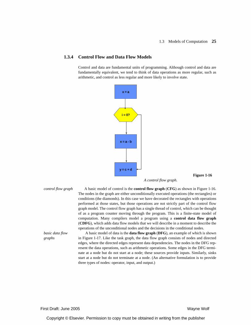
control flow graph A basic model of control is the control flow graph (CFG) as shown in Figure 1-16.The nodes in the graph are either unconditionally executed operations (the rectangles) orconditions (the diamonds). In this case we have decorated the rectangles with operationsperformed at those states, but those operations are not strictly part of the control flowgraph model. The control flow graph has a single thread of control, which can be thoughtof as a program counter moving through the program. This is a finite-state model ofcomputation. Many compilers model a program using a control data flow graph(CDFG), which adds data flow models that we will describe in a moment to describe theoperations of the unconditional nodes and the decisions in the conditional nodes.
basic data flow graphs
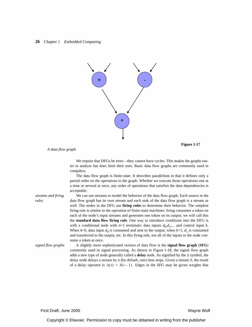
A basic model of data is the data flow graph (DFG), an example of which is shownin Figure 1-17. Like the task graph, the data flow graph consists of nodes and directededges, where the directed edges represent data dependencies. The nodes in the DFG rep-resent the data operations, such as arithmetic operations. Some edges in the DFG termi-nate at a node but do not start at a node; these sources provide inputs. Similarly, sinksstart at a node but do not terminate at a node. (An alternative formulation is to providethree types of nodes: operator, input, and output.)
Figure 1-16A control flow graph.
x = a - b
i = 0?
y = c + d
x = a
First Draft: June 2005 Wayne Wolf
Copyright © Elsevier. Permission to copy must be obtained in writing from the publisher
26 Chapter 1 Embedded Computing
We require that DFGs be trees—they cannot have cycles. This makes the graphs eas-ier to analyze but does limit their uses. Basic data flow graphs are commonly used incompilers.
The data flow graph is finite-state. It describes parallelism in that it defines only apartial order on the operations in the graph. Whether we execute those operations one ata time or several at once, any order of operations that satisfies the data dependencies isacceptable.
streams and firing rules
We can use streams to model the behavior of the data flow graph. Each source in thedata flow graph has its own stream and each sink of the data flow graph is a stream aswell. The nodes in the DFG use firing rules to determine their behavior. The simplestfiring rule is similar to the operation of finite-state machines: firing consumes a token oneach of the node’s input streams and generates one token on its output; we will call thisthe standard data flow firing rule. One way to introduce conditions into the DFG iswith a conditional node with n+1 terminals: data inputs d0,d1,... and control input k.When k=0, data input d0 is consumed and sent to the output; when k=1, d1 is consumedand transferred to the output, etc. In this firing rule, not all of the inputs to the node con-sume a token at once.
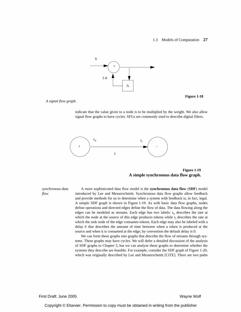
signal flow graphs A slightly more sophisticated version of data flow is the signal flow graph (SFG)commonly used in signal processing. As shown in Figure 1-18, the signal flow graphadds a new type of node generally called a delay node. As signified by the ∆ symbol, thedelay node delays a stream by n (by default, one) time steps. Given a stream S, the resultof a delay operator is . Edges in the SFG may be given weights that
Figure 1-17A data flow graph.
+ -
*
∆ t( ) S t 1–( )=
First Draft: June 2005 Wayne Wolf
Copyright © Elsevier. Permission to copy must be obtained in writing from the publisher
1.3 Models of Computation 27
indicate that the value given to a node is to be multiplied by the weight. We also allowsignal flow graphs to have cycles. SFGs are commonly used to describe digital filters.
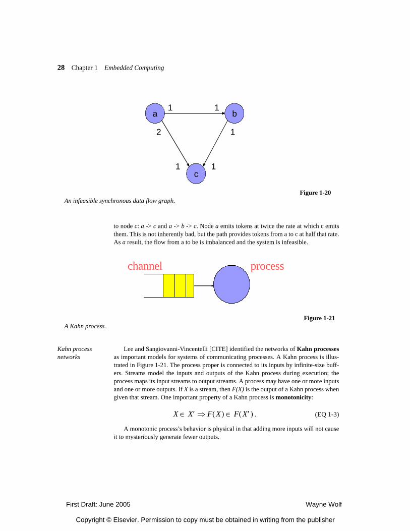
synchronous data flow
A more sophisticated data flow model is the synchronous data flow (SDF) modelintroduced by Lee and Messerschmitt. Synchronous data flow graphs allow feedbackand provide methods for us to determine when a system with feedback is, in fact, legal.A simple SDF graph is shown in Figure 1-19. As with basic data flow graphs, nodesdefine operations and directed edges define the flow of data. The data flowing along theedges can be modeled as streams. Each edge has two labels: ro describes the rate atwhich the node at the source of this edge produces tokens while ri describes the rate atwhich the sink node of the edge consumes tokens. Each edge may also be labeled with adelay δ that describes the amount of time between when a token is produced at thesource and when it is consumed at the edge; by convention the default delay is 0.
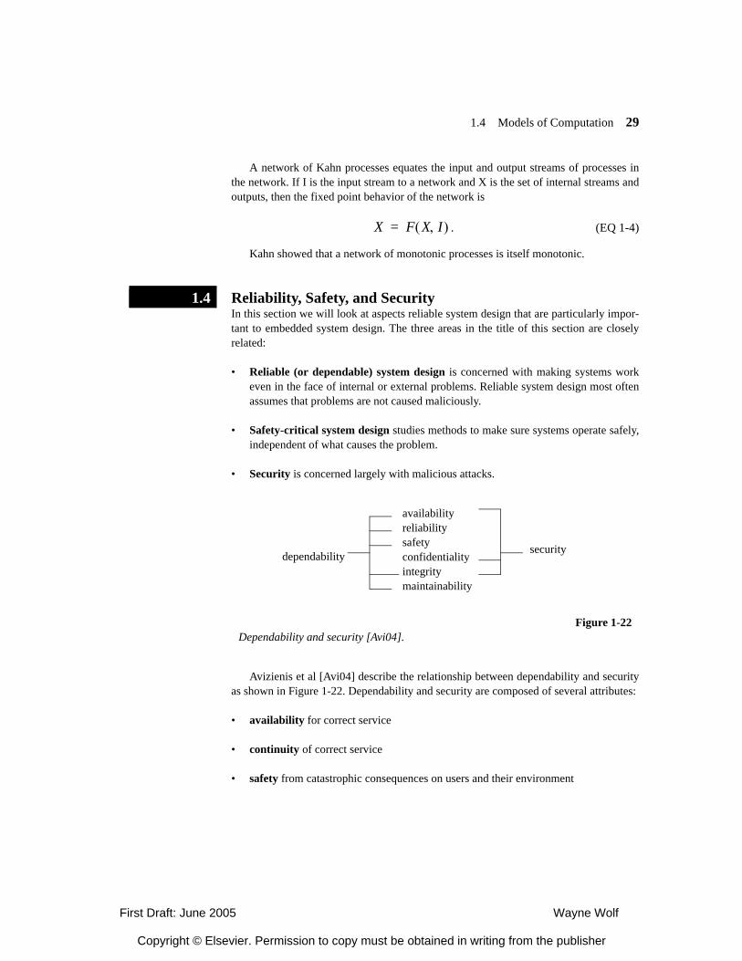
We can form these graphs into graphs that describe the flow of streams through sys-tems. These graphs may have cycles. We will defer a detailed discussion of the analysisof SDF graphs to Chapter 3, but we can analyze these graphs to determine whether thesystems they describe are feasible. For example, consider the SDF graph of Figure 1-20,which was originally described by Lee and Messerschmitt [CITE]. There are two paths
Figure 1-18A signal flow graph.
+
∆
k
1-k
Figure 1-19A simple synchronous data flow graph.
+ -
ro ri
δ
First Draft: June 2005 Wayne Wolf
Copyright © Elsevier. Permission to copy must be obtained in writing from the publisher
28 Chapter 1 Embedded Computing
to node c: a -> c and a -> b -> c. Node a emits tokens at twice the rate at which c emitsthem. This is not inherently bad, but the path provides tokens from a to c at half that rate.As a result, the flow from a to be is imbalanced and the system is infeasible.
Kahn process networks
Lee and Sangiovanni-Vincentelli [CITE] identified the networks of Kahn processesas important models for systems of communicating processes. A Kahn process is illus-trated in Figure 1-21. The process proper is connected to its inputs by infinite-size buff-ers. Streams model the inputs and outputs of the Kahn process during execution; theprocess maps its input streams to output streams. A process may have one or more inputsand one or more outputs. If X is a stream, then F(X) is the output of a Kahn process whengiven that stream. One important property of a Kahn process is monotonicity:
. (EQ 1-3)
A monotonic process’s behavior is physical in that adding more inputs will not causeit to mysteriously generate fewer outputs.
Figure 1-20An infeasible synchronous data flow graph.
a b
c
1 1
2
1 1
1
processchannel
Figure 1-21A Kahn process.
X X′∈ F X( ) F X′( )∈⇒
First Draft: June 2005 Wayne Wolf
Copyright © Elsevier. Permission to copy must be obtained in writing from the publisher
1.4 Models of Computation 29
A network of Kahn processes equates the input and output streams of processes inthe network. If I is the input stream to a network and X is the set of internal streams andoutputs, then the fixed point behavior of the network is
. (EQ 1-4)
Kahn showed that a network of monotonic processes is itself monotonic.
1.3.5 Reliability, Safety, and SecurityIn this section we will look at aspects reliable system design that are particularly impor-tant to embedded system design. The three areas in the title of this section are closelyrelated:
• Reliable (or dependable) system design is concerned with making systems workeven in the face of internal or external problems. Reliable system design most oftenassumes that problems are not caused maliciously.
• Safety-critical system design studies methods to make sure systems operate safely,independent of what causes the problem.
• Security is concerned largely with malicious attacks.
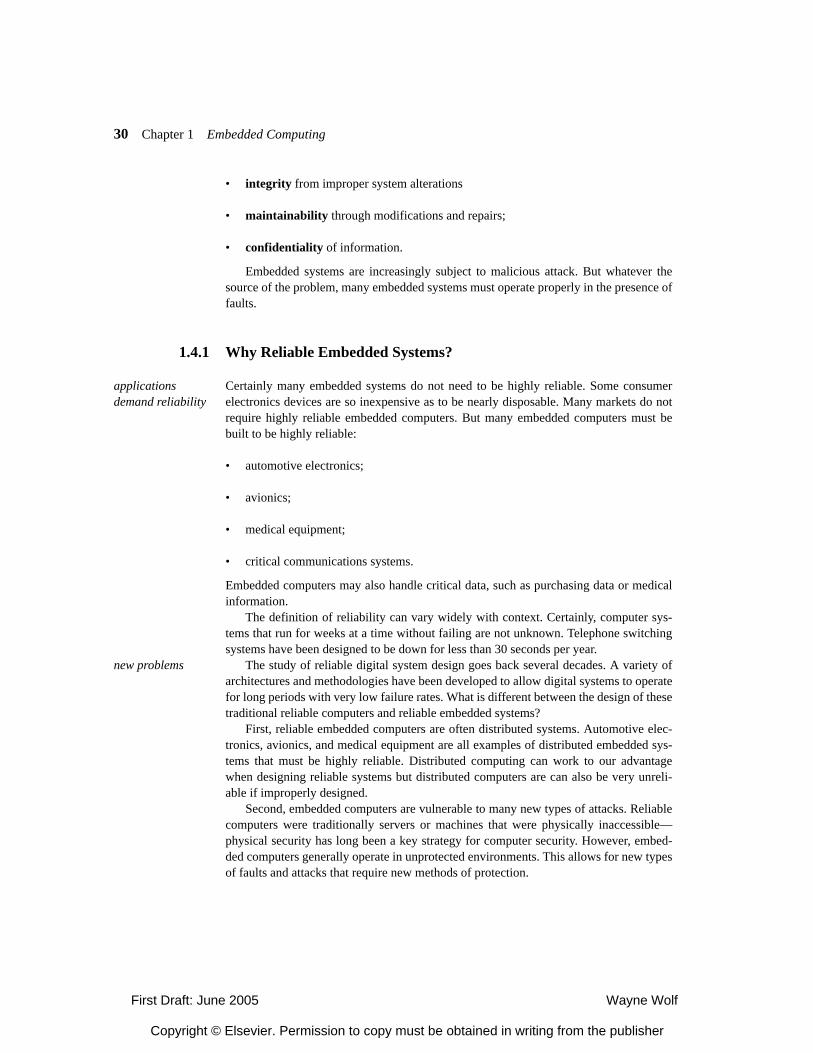
Avizienis et al [Avi04] describe the relationship between dependability and securityas shown in Figure 1-22. Dependability and security are composed of several attributes:
• availability for correct service
• continuity of correct service
• safety from catastrophic consequences on users and their environment
X F X I,( )=
1.4
availabilityreliabilitysafetyconfidentialityintegritymaintainability
dependability security
Figure 1-22Dependability and security [Avi04].
First Draft: June 2005 Wayne Wolf
Copyright © Elsevier. Permission to copy must be obtained in writing from the publisher
30 Chapter 1 Embedded Computing
• integrity from improper system alterations
• maintainability through modifications and repairs;
• confidentiality of information.
Embedded systems are increasingly subject to malicious attack. But whatever thesource of the problem, many embedded systems must operate properly in the presence offaults.
1.4.1 Why Reliable Embedded Systems?
applications demand reliability
Certainly many embedded systems do not need to be highly reliable. Some consumerelectronics devices are so inexpensive as to be nearly disposable. Many markets do notrequire highly reliable embedded computers. But many embedded computers must bebuilt to be highly reliable:
• automotive electronics;
• avionics;
• medical equipment;
• critical communications systems.
Embedded computers may also handle critical data, such as purchasing data or medicalinformation.
The definition of reliability can vary widely with context. Certainly, computer sys-tems that run for weeks at a time without failing are not unknown. Telephone switchingsystems have been designed to be down for less than 30 seconds per year.
new problems The study of reliable digital system design goes back several decades. A variety ofarchitectures and methodologies have been developed to allow digital systems to operatefor long periods with very low failure rates. What is different between the design of thesetraditional reliable computers and reliable embedded systems?
First, reliable embedded computers are often distributed systems. Automotive elec-tronics, avionics, and medical equipment are all examples of distributed embedded sys-tems that must be highly reliable. Distributed computing can work to our advantagewhen designing reliable systems but distributed computers are can also be very unreli-able if improperly designed.
Second, embedded computers are vulnerable to many new types of attacks. Reliablecomputers were traditionally servers or machines that were physically inaccessible—physical security has long been a key strategy for computer security. However, embed-ded computers generally operate in unprotected environments. This allows for new typesof faults and attacks that require new methods of protection.
First Draft: June 2005 Wayne Wolf
Copyright © Elsevier. Permission to copy must be obtained in writing from the publisher
1.4 Models of Computation 31
1.4.2 Fundamentals of Reliable System Design
sources of faults Reliable systems are designed to recover from faults. A fault may be permanent ortransient. A fault may have many sources:
• Physical faults come from manufacturing defects, radiation hazards, etc.
• Design faults are the result of improperly designed systems.
• Operational faults come from human error, security breaches, poorly designedhuman-computer interfaces, etc.
While the details of how these faults happen and how they affect the system may vary,the system’s users do not really care what caused a problem, only that the system reactedproperly to the problem. Whether a fault comes from a manufacturing defect or a secu-rity problem, the system must react in such a way to minimize the fault’s effect on theuser.
system reliability metrics
Users judge systems by how reliable they are, not by the problems that cause them tofail. Several metrics are used to quantify system reliability {Sie98].
Mean time to failure (MTTF) is one well-known metric. Given a set of perfectlyfunctioning systems at time 0, MTTF is the expected time for the first system in that setto fail. Although it is defined for a large set of systems, it is also often used to character-ize the reliability of a single system. The mean time to failure can be calculated by
(EQ 1-5)
where R(t) is the reliability function of the system.The reliability function of a system describes the probability that the system will
operate correctly in the time period . R(0) = 1 and R(t) monotonically decreases withtime.
The hazard function z(t) is the failure rate of components. For a given probabilityfunction, the hazard function is defined as
. (EQ 1-6)
characterizing faults
Faults may be measured empirically or modeled by a probability distribution. Empir-ical studies are usually the basis for choosing an appropriate probability distribution.One common model for failures is the exponential distribution. In this case, the hazardfunction is
MTTF R t( )d0
∞
∫=
0 t,[ ]
t( ) pdf1 CDF–-------------------=
First Draft: June 2005 Wayne Wolf
Copyright © Elsevier. Permission to copy must be obtained in writing from the publisher
32 Chapter 1 Embedded Computing
. (EQ 1-7)
Another function used to model failures is the Weibull distribution:
. (EQ 1-8)
In this formula, α is known as the shape parameter and λ is known as the scaleparameter. The Weibull distribution must normally be solved numerically.
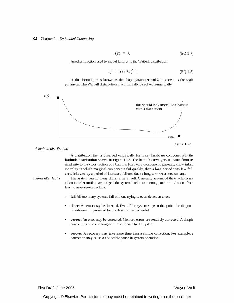
A distribution that is observed empirically for many hardware components is thebathtub distribution shown in Figure 1-23. The bathtub curve gets its name from itssimilarity to the cross section of a bathtub. Hardware components generally show infantmortality in which marginal components fail quickly, then a long period with few fail-ures, followed by a period of increased failures due to long-term wear mechanisms.
actions after faults The system can do many things after a fault. Generally several of these actions aretaken in order until an action gets the system back into running condition. Actions fromleast to most severe include:
n fail All too many systems fail without trying to even detect an error.
• detect An error may be detected. Even if the system stops at this point, the diagnos-tic information provided by the detector can be useful.
• correct An error may be corrected. Memory errors are routinely corrected. A simplecorrection causes no long-term disturbance to the system.
• recover A recovery may take more time than a simple correction. For example, acorrection may cause a noticeable pause in system operation.
z t( ) λ=
t( ) αλ λt( )α –=
Figure 1-23A bathtub distribution.
time
z(t)
this should look more like a bathtubwith a flat bottom
First Draft: June 2005 Wayne Wolf
Copyright © Elsevier. Permission to copy must be obtained in writing from the publisher
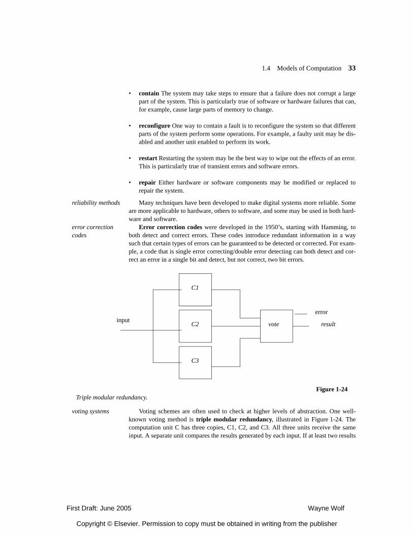
1.4 Models of Computation 33
• contain The system may take steps to ensure that a failure does not corrupt a largepart of the system. This is particularly true of software or hardware failures that can,for example, cause large parts of memory to change.
• reconfigure One way to contain a fault is to reconfigure the system so that differentparts of the system perform some operations. For example, a faulty unit may be dis-abled and another unit enabled to perform its work.
• restart Restarting the system may be the best way to wipe out the effects of an error.This is particularly true of transient errors and software errors.
• repair Either hardware or software components may be modified or replaced torepair the system.
reliability methods Many techniques have been developed to make digital systems more reliable. Someare more applicable to hardware, others to software, and some may be used in both hard-ware and software.
error correction codes
Error correction codes were developed in the 1950’s, starting with Hamming, toboth detect and correct errors. These codes introduce redundant information in a waysuch that certain types of errors can be guaranteed to be detected or corrected. For exam-ple, a code that is single error correcting/double error detecting can both detect and cor-rect an error in a single bit and detect, but not correct, two bit errors.
voting systems Voting schemes are often used to check at higher levels of abstraction. One well-known voting method is triple modular redundancy, illustrated in Figure 1-24. Thecomputation unit C has three copies, C1, C2, and C3. All three units receive the sameinput. A separate unit compares the results generated by each input. If at least two results
Figure 1-24Triple modular redundancy.
C1
C2
C3
resultvoteinputerror
First Draft: June 2005 Wayne Wolf
Copyright © Elsevier. Permission to copy must be obtained in writing from the publisher
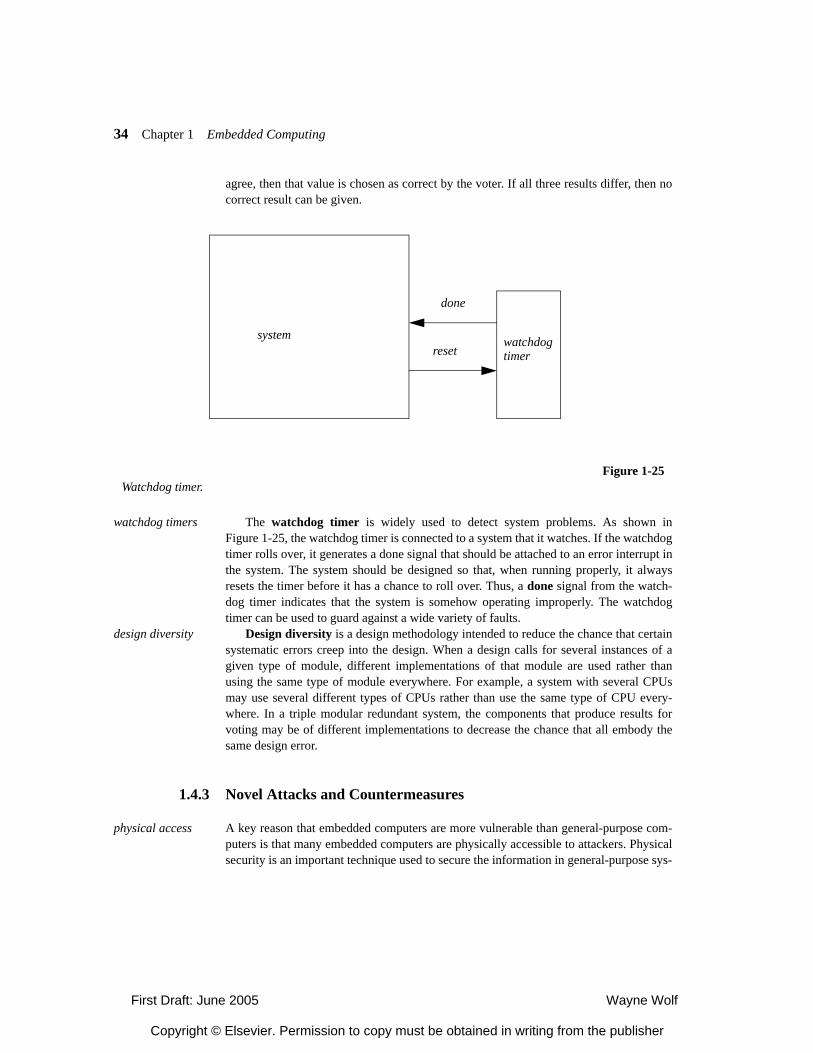
34 Chapter 1 Embedded Computing
agree, then that value is chosen as correct by the voter. If all three results differ, then nocorrect result can be given.
watchdog timers The watchdog timer is widely used to detect system problems. As shown inFigure 1-25, the watchdog timer is connected to a system that it watches. If the watchdogtimer rolls over, it generates a done signal that should be attached to an error interrupt inthe system. The system should be designed so that, when running properly, it alwaysresets the timer before it has a chance to roll over. Thus, a done signal from the watch-dog timer indicates that the system is somehow operating improperly. The watchdogtimer can be used to guard against a wide variety of faults.
design diversity Design diversity is a design methodology intended to reduce the chance that certainsystematic errors creep into the design. When a design calls for several instances of agiven type of module, different implementations of that module are used rather thanusing the same type of module everywhere. For example, a system with several CPUsmay use several different types of CPUs rather than use the same type of CPU every-where. In a triple modular redundant system, the components that produce results forvoting may be of different implementations to decrease the chance that all embody thesame design error.
1.4.3 Novel Attacks and Countermeasures
physical access A key reason that embedded computers are more vulnerable than general-purpose com-puters is that many embedded computers are physically accessible to attackers. Physicalsecurity is an important technique used to secure the information in general-purpose sys-
Figure 1-25Watchdog timer.
watchdogtimer
systemreset
done
First Draft: June 2005 Wayne Wolf
Copyright © Elsevier. Permission to copy must be obtained in writing from the publisher
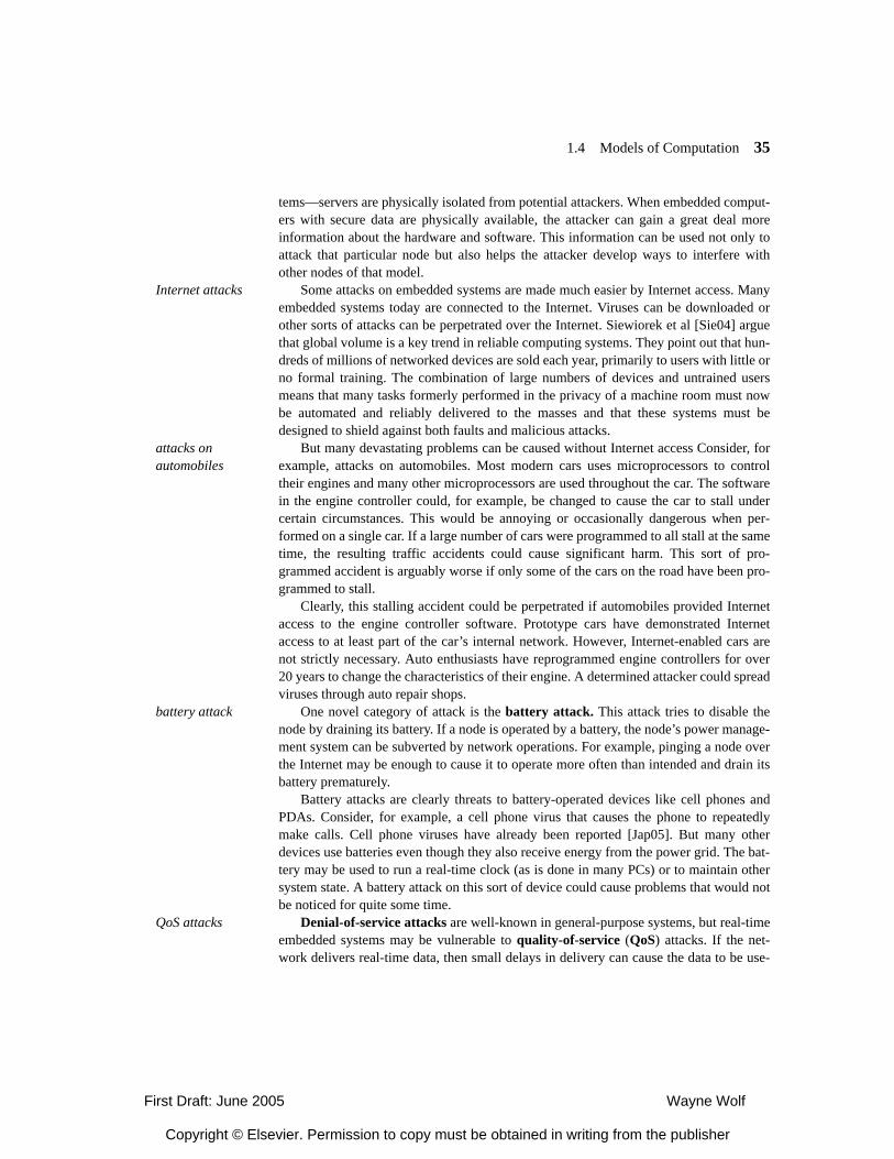
1.4 Models of Computation 35
tems—servers are physically isolated from potential attackers. When embedded comput-ers with secure data are physically available, the attacker can gain a great deal moreinformation about the hardware and software. This information can be used not only toattack that particular node but also helps the attacker develop ways to interfere withother nodes of that model.
Internet attacks Some attacks on embedded systems are made much easier by Internet access. Manyembedded systems today are connected to the Internet. Viruses can be downloaded orother sorts of attacks can be perpetrated over the Internet. Siewiorek et al [Sie04] arguethat global volume is a key trend in reliable computing systems. They point out that hun-dreds of millions of networked devices are sold each year, primarily to users with little orno formal training. The combination of large numbers of devices and untrained usersmeans that many tasks formerly performed in the privacy of a machine room must nowbe automated and reliably delivered to the masses and that these systems must bedesigned to shield against both faults and malicious attacks.
attacks on automobiles
But many devastating problems can be caused without Internet access Consider, forexample, attacks on automobiles. Most modern cars uses microprocessors to controltheir engines and many other microprocessors are used throughout the car. The softwarein the engine controller could, for example, be changed to cause the car to stall undercertain circumstances. This would be annoying or occasionally dangerous when per-formed on a single car. If a large number of cars were programmed to all stall at the sametime, the resulting traffic accidents could cause significant harm. This sort of pro-grammed accident is arguably worse if only some of the cars on the road have been pro-grammed to stall.
Clearly, this stalling accident could be perpetrated if automobiles provided Internetaccess to the engine controller software. Prototype cars have demonstrated Internetaccess to at least part of the car’s internal network. However, Internet-enabled cars arenot strictly necessary. Auto enthusiasts have reprogrammed engine controllers for over20 years to change the characteristics of their engine. A determined attacker could spreadviruses through auto repair shops.
battery attack One novel category of attack is the battery attack. This attack tries to disable thenode by draining its battery. If a node is operated by a battery, the node’s power manage-ment system can be subverted by network operations. For example, pinging a node overthe Internet may be enough to cause it to operate more often than intended and drain itsbattery prematurely.
Battery attacks are clearly threats to battery-operated devices like cell phones andPDAs. Consider, for example, a cell phone virus that causes the phone to repeatedlymake calls. Cell phone viruses have already been reported [Jap05]. But many otherdevices use batteries even though they also receive energy from the power grid. The bat-tery may be used to run a real-time clock (as is done in many PCs) or to maintain othersystem state. A battery attack on this sort of device could cause problems that would notbe noticed for quite some time.
QoS attacks Denial-of-service attacks are well-known in general-purpose systems, but real-timeembedded systems may be vulnerable to quality-of-service (QoS) attacks. If the net-work delivers real-time data, then small delays in delivery can cause the data to be use-
First Draft: June 2005 Wayne Wolf
Copyright © Elsevier. Permission to copy must be obtained in writing from the publisher
36 Chapter 1 Embedded Computing
less. If that data is used for real-time control, then those small delays can cause thesystem to fail. We also refer to this as a timing attack because it changes the real-timecharacteristics of the system. A QoS or timing attack is powerful because its effects arenot just limited to information. The dynamics of the system being controlled help todetermine the response of the system. A relatively small change in timing can cause agreat deal of damage if a large, heavy, fast-moving object is being controlled.
attacks on sensor networks
Wood and Stankovic [Woo02] identified a number of ways to perform denial-of-ser-vice attacks on sensor networks at different levels of the network hierarchy:
• physical layer jamming, tampering
• link layer collision, exhaustion, unfairness
• network and routing layer neglect and greed, horning, misdirection, black holes,authorization, probing, redundancy
• transport layer flooding, desynchronization
power attack An example of an attack that is much more easily used against embedded computersthan general-purpose computers is the power attack. Karcher showed that measure-ments of the power supply current of a CPU can be used to determine a great deal aboutthe processor’s internal activity. Karcher used differential power analysis to determinethe bits in cryptokeys—the processor performed different operations for the 1 and 0 case,which consumed different amounts of power. This attack was originally aimed at smartcards, which draw their power from the external card reader, but it can be applied tomany embedded systems.
Figure 1-26 illustrates two methods of power attacks developed by Karcher. Simplepower analysis inspects a trace manually and tries to determine the location of programactions such as branches, based upon knowledge of the power consumption of variousCPU operations. Based upon program actions, the attacker then deduces bits of the key.Differential power analysis uses correlation to identify actions and key bits.
physical security In some cases it may be possible to build tamper-resistant embedded systems. Mak-ing the electronic devices hard to reveal and analyze will slow down attackers. Limitinginformation within a chip also helps make data harder for attackers to reveal.
Kahn networks Example Applications
Some knowledge of the applications that will run on an embedded system will run is ofgreat help to system designers. In this section we will look at some basic concepts in twocommon applications, communications/networking and multimedia.
1.5
First Draft: June 2005 Wayne Wolf
Copyright © Elsevier. Permission to copy must be obtained in writing from the publisher
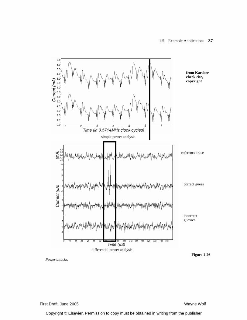
1.5 Example Applications 37
Figure 1-26Power attacks.
simple power analysis
differential power analysis
reference trace
correct guess
incorrectguesses
from Karchercheck cite,copyright
First Draft: June 2005 Wayne Wolf
Copyright © Elsevier. Permission to copy must be obtained in writing from the publisher
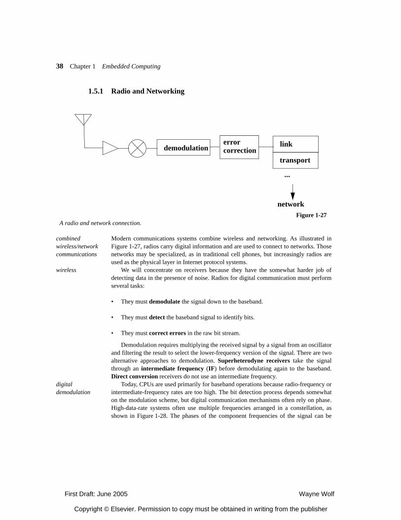
38 Chapter 1 Embedded Computing
1.5.1 Radio and Networking
combined wireless/network communications
Modern communications systems combine wireless and networking. As illustrated inFigure 1-27, radios carry digital information and are used to connect to networks. Thosenetworks may be specialized, as in traditional cell phones, but increasingly radios areused as the physical layer in Internet protocol systems.
wireless We will concentrate on receivers because they have the somewhat harder job ofdetecting data in the presence of noise. Radios for digital communication must performseveral tasks:
• They must demodulate the signal down to the baseband.
• They must detect the baseband signal to identify bits.
• They must correct errors in the raw bit stream.
Demodulation requires multiplying the received signal by a signal from an oscillatorand filtering the result to select the lower-frequency version of the signal. There are twoalternative approaches to demodulation. Superheterodyne receivers take the signalthrough an intermediate frequency (IF) before demodulating again to the baseband.Direct conversion receivers do not use an intermediate frequency.
digital demodulation
Today, CPUs are used primarily for baseband operations because radio-frequency orintermediate-frequency rates are too high. The bit detection process depends somewhaton the modulation scheme, but digital communication mechanisms often rely on phase.High-data-rate systems often use multiple frequencies arranged in a constellation, asshown in Figure 1-28. The phases of the component frequencies of the signal can be
demodulationerrorcorrection
link
transport
...
networkFigure 1-27
A radio and network connection.
First Draft: June 2005 Wayne Wolf
Copyright © Elsevier. Permission to copy must be obtained in writing from the publisher
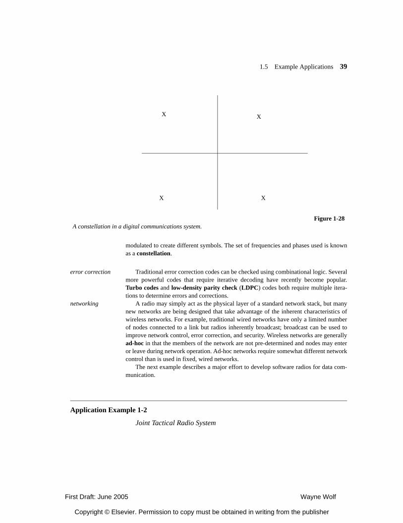
1.5 Example Applications 39
modulated to create different symbols. The set of frequencies and phases used is knownas a constellation.
error correction Traditional error correction codes can be checked using combinational logic. Severalmore powerful codes that require iterative decoding have recently become popular.Turbo codes and low-density parity check (LDPC) codes both require multiple itera-tions to determine errors and corrections.
networking A radio may simply act as the physical layer of a standard network stack, but manynew networks are being designed that take advantage of the inherent characteristics ofwireless networks. For example, traditional wired networks have only a limited numberof nodes connected to a link but radios inherently broadcast; broadcast can be used toimprove network control, error correction, and security. Wireless networks are generallyad-hoc in that the members of the network are not pre-determined and nodes may enteror leave during network operation. Ad-hoc networks require somewhat different networkcontrol than is used in fixed, wired networks.
The next example describes a major effort to develop software radios for data com-munication.
Application Example 1-2
Joint Tactical Radio System
X
XX
X
Figure 1-28A constellation in a digital communications system.
First Draft: June 2005 Wayne Wolf
Copyright © Elsevier. Permission to copy must be obtained in writing from the publisher
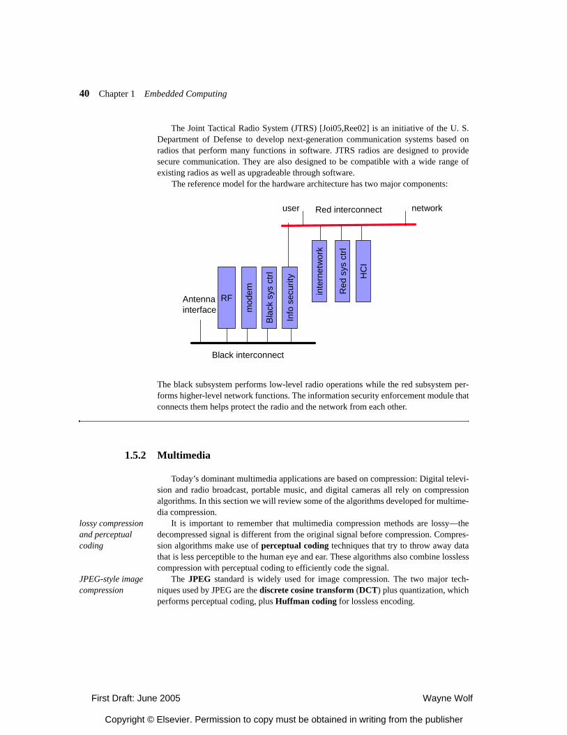
40 Chapter 1 Embedded Computing
The Joint Tactical Radio System (JTRS) [Joi05,Ree02] is an initiative of the U. S.Department of Defense to develop next-generation communication systems based onradios that perform many functions in software. JTRS radios are designed to providesecure communication. They are also designed to be compatible with a wide range ofexisting radios as well as upgradeable through software.
The reference model for the hardware architecture has two major components:
The black subsystem performs low-level radio operations while the red subsystem per-forms higher-level network functions. The information security enforcement module thatconnects them helps protect the radio and the network from each other.
1.5.2 Multimedia
Today’s dominant multimedia applications are based on compression: Digital televi-sion and radio broadcast, portable music, and digital cameras all rely on compressionalgorithms. In this section we will review some of the algorithms developed for multime-dia compression.
lossy compression and perceptual coding
It is important to remember that multimedia compression methods are lossy—thedecompressed signal is different from the original signal before compression. Compres-sion algorithms make use of perceptual coding techniques that try to throw away datathat is less perceptible to the human eye and ear. These algorithms also combine losslesscompression with perceptual coding to efficiently code the signal.
JPEG-style image compression
The JPEG standard is widely used for image compression. The two major tech-niques used by JPEG are the discrete cosine transform (DCT) plus quantization, whichperforms perceptual coding, plus Huffman coding for lossless encoding.
Black interconnect
Antennainterface
RF
mod
em
Bla
ck s
ys c
trl
Info
sec
urity
Red interconnectuser network
Red
sys
ctrl
HC
I
inte
rnet
wor
k
First Draft: June 2005 Wayne Wolf
Copyright © Elsevier. Permission to copy must be obtained in writing from the publisher
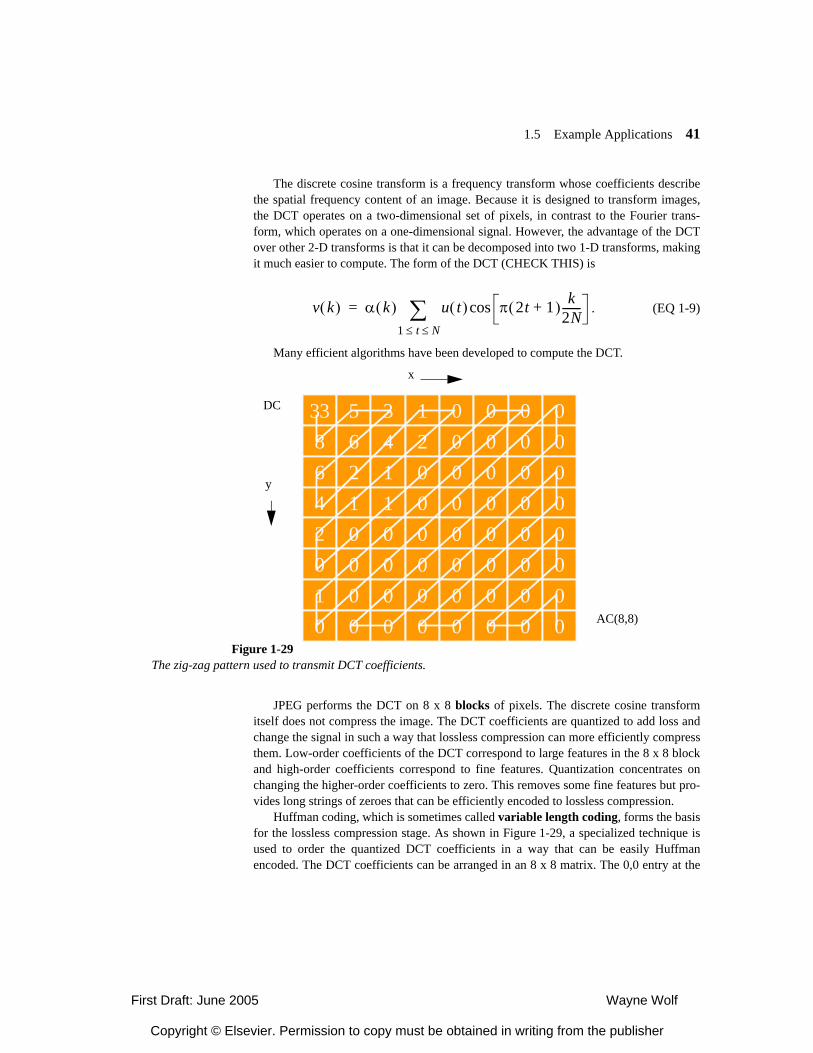
1.5 Example Applications 41
The discrete cosine transform is a frequency transform whose coefficients describethe spatial frequency content of an image. Because it is designed to transform images,the DCT operates on a two-dimensional set of pixels, in contrast to the Fourier trans-form, which operates on a one-dimensional signal. However, the advantage of the DCTover other 2-D transforms is that it can be decomposed into two 1-D transforms, makingit much easier to compute. The form of the DCT (CHECK THIS) is
. (EQ 1-9)
Many efficient algorithms have been developed to compute the DCT.
JPEG performs the DCT on 8 x 8 blocks of pixels. The discrete cosine transformitself does not compress the image. The DCT coefficients are quantized to add loss andchange the signal in such a way that lossless compression can more efficiently compressthem. Low-order coefficients of the DCT correspond to large features in the 8 x 8 blockand high-order coefficients correspond to fine features. Quantization concentrates onchanging the higher-order coefficients to zero. This removes some fine features but pro-vides long strings of zeroes that can be efficiently encoded to lossless compression.
Huffman coding, which is sometimes called variable length coding, forms the basisfor the lossless compression stage. As shown in Figure 1-29, a specialized technique isused to order the quantized DCT coefficients in a way that can be easily Huffmanencoded. The DCT coefficients can be arranged in an 8 x 8 matrix. The 0,0 entry at the
v k( ) α k( ) u t( ) π 2t 1+( ) k2N-------cos
1 t N≤ ≤∑=
33 5 3 1 0 0 0 08 6 4 2 0 0 0 0642010
2 1 0 0 0 0 01 1 0 0 0 0 00 0 0 0 0 0 00 0 0 0 0 0 00 0 0 0 0 0 00 0 0 0 0 0 0
Figure 1-29The zig-zag pattern used to transmit DCT coefficients.
DC
x
y
AC(8,8)
First Draft: June 2005 Wayne Wolf
Copyright © Elsevier. Permission to copy must be obtained in writing from the publisher
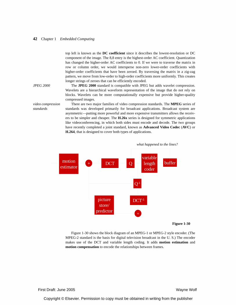
42 Chapter 1 Embedded Computing
top left is known as the DC coefficient since it describes the lowest-resolution or DCcomponent of the image. The 8,8 entry is the highest-order AC coefficient. Quantizationhas changed the higher-order AC coefficients to 0. If we were to traverse the matrix inrow or column order, we would intersperse non-zero lower-order coefficients withhigher-order coefficients that have been zeroed. By traversing the matrix in a zig-zagpattern, we move from low-order to high-order coefficients more uniformly. This createslonger strings of zeroes that can be efficiently encoded.
JPEG 2000 The JPEG 2000 standard is compatible with JPEG but adds wavelet compression.Wavelets are a hierarchical waveform representation of the image that do not rely onblocks. Wavelets can be more computationally expensive but provide higher-qualitycompressed images.
video compression standards
There are two major families of video compression standards. The MPEG series ofstandards was developed primarily for broadcast applications. Broadcast system areasymmetric—putting more powerful and more expensive transmitters allows the receiv-ers to be simpler and cheaper. The H.26x series is designed for symmetric applicationslike videoconferencing, in which both sides must encode and decode. The two groupshave recently completed a joint standard, known as Advanced Video Codec (AVC) orH.264, that is designed to cover both types of applications.
Figure 1-30 shows the block diagram of an MPEG-1 or MPEG-2 style encoder. (TheMPEG-2 standard is the basis for digital television broadcast in the U. S.) The encodermakes use of the DCT and variable length coding. It adds motion estimation andmotion compensation to encode the relationships between frames.
Figure 1-30
motionestimator
+ DCT Qvariablelengthcoder
buffer
Q-1
DCT-1
+
picturestore/
predictor
what happened to the lines?
First Draft: June 2005 Wayne Wolf
Copyright © Elsevier. Permission to copy must be obtained in writing from the publisher

1.6 Example Applications 43
motion estimation Motion estimation allows one frame to be encoded as translational motion fromanother frame. Motion estimation is performed on 16 x 16 macroblocks. A macroblockfrom one frame is selected and a search area in the reference frame is searched to findan identical or closely matching macroblock. Search reports an offset for the macroblockin the search area that provides the best match. That position describes a motion vectorfor the macroblock. During decompression, motion compensation copies the block to theposition specified by the motion vector, thus saving the system from transmitting theentire image.
error signal Motion estimation does not perfectly predict a frame because elements of the blockmay move, the search may not provide the exact match, etc. An error signal is also trans-mitted to correct for small imperfections in the signal. The inverse DCT and picture/storepredictor in the feedback are used to generate the uncompressed version of the lossilycompressed signal that would be seen by the receiver; that reconstruction is used to gen-erate the error signal.
SummaryThe designers of high-performance embedded computing systems are required to masterseveral skill. They must be expert at system specification, not only in the informal sensebut also in creating executable models. They must understand the basic architecturaltechniques for both hardware and software. They must be able to analyze performanceand energy consumption for both hardware and software. And they must be able to maketrade-offs between hardware and software at all stages in the design process.
Figure 1-31Motion estimation.
searcharea
motionvector
searcharea
1.6
First Draft: June 2005 Wayne Wolf
Copyright © Elsevier. Permission to copy must be obtained in writing from the publisher
44 Chapter 1 Embedded Computing
During the remainder of this book, we will see many important design techniquesthat can be used in embedded system design methodologies. We will proceed largelybottom-up. We will first study hardware and software for uniprocessor systems. We willthen consider hardware/software co-design. We will then move on to the multiprocessortechniques that underlie modern high-performance embedded systems.
What We Learned
• Many embedded computing systems are based upon standards. The form in whichthe standard is expressed affects the methodology we use to design the embeddedsystem.
• Embedded systems are open to new types of security and reliability threats. Embed-ded computers that perform real-time control pose particular concerns.
Further Reading
The team of Lee and Sangiovanni-Vincentelli created the study of models of computa-tion for embedded computing. Siewiorek and Swarz [Sie96] is the classical text on reli-able computer system design. Storey [Sto96] provides a detailed description of safety-critical computers. Lee’s book describes digital communication.
Questions
Q1-1 What are the essential characteristics of embedded computing systems?
Q1-2 What are the important characteristics of a software design methodology for embeddedcomputing systems? A hardware design methodology? A complete hardware/softwaremethodology?
Q1-3 What are the essential properties of a data flow graph?
Q1-4 What are the essential properties of a Petri net?
First Draft: June 2005 Wayne Wolf
Copyright © Elsevier. Permission to copy must be obtained in writing from the publisher
1.6 Example Applications 45
Lab Exercises
L1-1 Select a device of your choice and determine whether it uses embedded computers.Determine, to the extent possible, the internal hardware architecture of the device.
L1-2 How can you make an FSM and a data flow graph communicate in a reliable fashion?
L1-3 How much computation must be done to demodulate a CMDA2000 signal?
First Draft: June 2005 Wayne Wolf
Copyright © Elsevier. Permission to copy must be obtained in writing from the publisher

46 Chapter 1 Embedded Computing
First Draft: June 2005 Wayne Wolf
Copyright © Elsevier. Permission to copy must be obtained in writing from the publisher
First Draft: Aug 2005 Wayne Wolf
Copyright © Elsevier. Permission to copy must be obtained in writing from the publisher
2
Chapter
2CPUs 1
• Architectural mechanisms for embedded processors.
• Parallelism in embedded CPUs.
• Code compression and bus encoding.
• Security mechanisms.
• CPU simulation.
Introduction
CPUs are at the heart of embedded systems. Whether we use one CPU or combine sev-eral CPUs to build a multiprocessor, instruction set execution provides the combinationof efficiency and generality that make embedded computing powerful.
A number of CPUs have been designed especially for embedded applications oradapted from other uses. We can also use design tools to create CPUs to match the char-acteristics of our application. In either case, a variety of mechanisms can be used tomatch the CPU characteristics to the job at hand. Some of these mechanisms are bor-rowed from general-purpose computing; others have been developed especially forembedded systems.
We will start with a brief introduction to the CPU design space. We will then look atthe major categories of processors: RISC and DSP in Section 2.3; VLIW, superscalar,and related methods in Section 2.4. Section 2.5 considers novel variable-performancetechniques such as better-than-worst-case design. In Section 2.6 we will study the designof memory hierarchies. Section 2.7 looks at additional CPU mechanisms like code com-pression and bus encoding. Section 2.8 surveys techniques for CPU simulation.Section 2.9 introduces some methodologies and techniques for the design of custom pro-cessors.
2.1
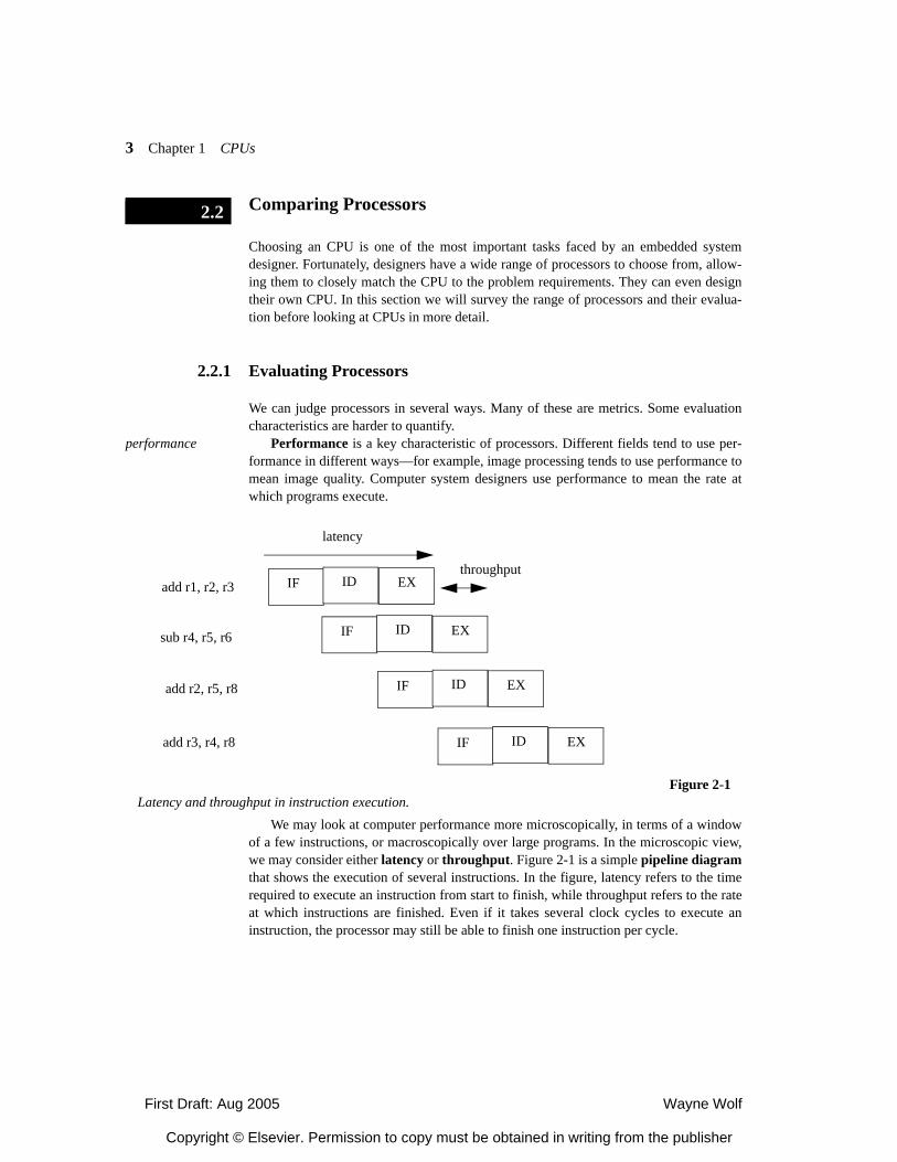
First Draft: Aug 2005 Wayne Wolf
Copyright © Elsevier. Permission to copy must be obtained in writing from the publisher
3 Chapter 1 CPUs
Comparing Processors
Choosing an CPU is one of the most important tasks faced by an embedded systemdesigner. Fortunately, designers have a wide range of processors to choose from, allow-ing them to closely match the CPU to the problem requirements. They can even designtheir own CPU. In this section we will survey the range of processors and their evalua-tion before looking at CPUs in more detail.
2.2.1 Evaluating Processors
We can judge processors in several ways. Many of these are metrics. Some evaluationcharacteristics are harder to quantify.
performance Performance is a key characteristic of processors. Different fields tend to use per-formance in different ways—for example, image processing tends to use performance tomean image quality. Computer system designers use performance to mean the rate atwhich programs execute.
We may look at computer performance more microscopically, in terms of a windowof a few instructions, or macroscopically over large programs. In the microscopic view,we may consider either latency or throughput. Figure 2-1 is a simple pipeline diagramthat shows the execution of several instructions. In the figure, latency refers to the timerequired to execute an instruction from start to finish, while throughput refers to the rateat which instructions are finished. Even if it takes several clock cycles to execute aninstruction, the processor may still be able to finish one instruction per cycle.
2.2
add r1, r2, r3
sub r4, r5, r6
add r2, r5, r8
add r3, r4, r8
Figure 2-1Latency and throughput in instruction execution.
latency
throughputIF ID EX
IF ID EX
IF ID EX
IF ID EX
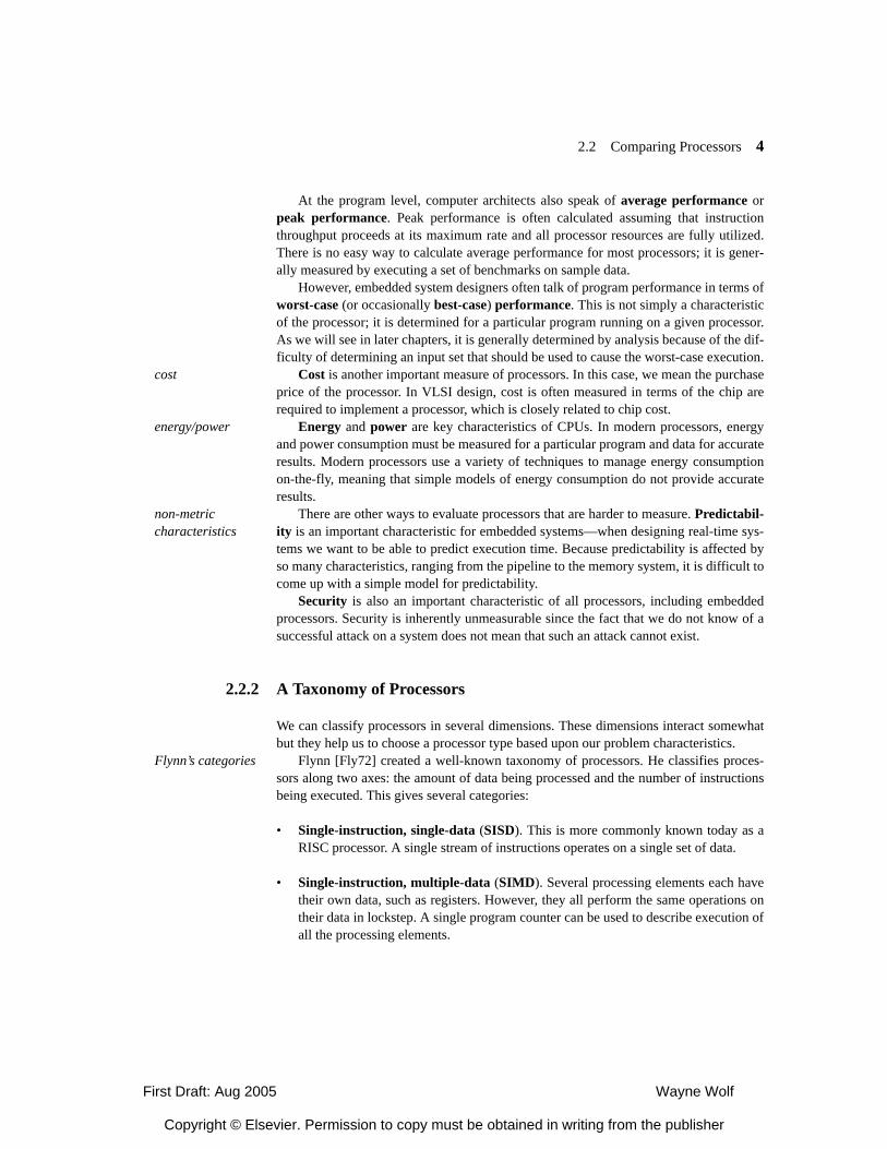
First Draft: Aug 2005 Wayne Wolf
Copyright © Elsevier. Permission to copy must be obtained in writing from the publisher
2.2 Comparing Processors 4
At the program level, computer architects also speak of average performance orpeak performance. Peak performance is often calculated assuming that instructionthroughput proceeds at its maximum rate and all processor resources are fully utilized.There is no easy way to calculate average performance for most processors; it is gener-ally measured by executing a set of benchmarks on sample data.
However, embedded system designers often talk of program performance in terms ofworst-case (or occasionally best-case) performance. This is not simply a characteristicof the processor; it is determined for a particular program running on a given processor.As we will see in later chapters, it is generally determined by analysis because of the dif-ficulty of determining an input set that should be used to cause the worst-case execution.
cost Cost is another important measure of processors. In this case, we mean the purchaseprice of the processor. In VLSI design, cost is often measured in terms of the chip arerequired to implement a processor, which is closely related to chip cost.
energy/power Energy and power are key characteristics of CPUs. In modern processors, energyand power consumption must be measured for a particular program and data for accurateresults. Modern processors use a variety of techniques to manage energy consumptionon-the-fly, meaning that simple models of energy consumption do not provide accurateresults.
non-metric characteristics
There are other ways to evaluate processors that are harder to measure. Predictabil-ity is an important characteristic for embedded systems—when designing real-time sys-tems we want to be able to predict execution time. Because predictability is affected byso many characteristics, ranging from the pipeline to the memory system, it is difficult tocome up with a simple model for predictability.
Security is also an important characteristic of all processors, including embeddedprocessors. Security is inherently unmeasurable since the fact that we do not know of asuccessful attack on a system does not mean that such an attack cannot exist.
2.2.2 A Taxonomy of Processors
We can classify processors in several dimensions. These dimensions interact somewhatbut they help us to choose a processor type based upon our problem characteristics.
Flynn’s categories Flynn [Fly72] created a well-known taxonomy of processors. He classifies proces-sors along two axes: the amount of data being processed and the number of instructionsbeing executed. This gives several categories:
• Single-instruction, single-data (SISD). This is more commonly known today as aRISC processor. A single stream of instructions operates on a single set of data.
• Single-instruction, multiple-data (SIMD). Several processing elements each havetheir own data, such as registers. However, they all perform the same operations ontheir data in lockstep. A single program counter can be used to describe execution ofall the processing elements.
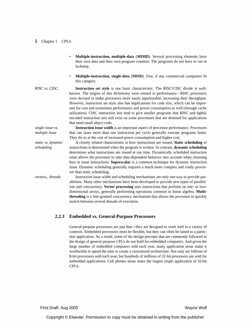
First Draft: Aug 2005 Wayne Wolf
Copyright © Elsevier. Permission to copy must be obtained in writing from the publisher
5 Chapter 1 CPUs
• Multiple-instruction, multiple-data (MIMD). Several processing elements havetheir own data and their own program counters. The programs do not have to run inlockstep.
• Multiple-instruction, single-data (MISD). Few, if any commercial computers fitthis category.
RISC vs. CISC Instruction set style is one basic characteristic. The RISC/CISC divide is well-known. The origins of this dichotomy were related to performance—RISC processorswere devised to make processors more easily pipelineable, increasing their throughput.However, instruction set style also has implications for code size, which can be impor-tant for cost and sometimes performance and power consumption as well (through cacheutilization). CISC instruction sets tend to give smaller programs that RISC and tightlyencoded instruction sets still exist on some processors that are destined for applicationsthat need small object code.
single issue vs. multiple issue
Instruction issue width is an important aspect of processor performance. Processorsthat can issue more than one instruction per cycle generally execute programs faster.They do so at the cost of increased power consumption and higher cost.
static vs. dynamic scheduling
A closely related characteristic is how instructions are issued. Static scheduling ofinstructions is determined when the program is written. In contrast, dynamic schedulingdetermines what instructions are issued at run time. Dynamically scheduled instructionissue allows the processor to take data-dependent behavior into account when choosinghow to issue instructions. Superscalar is a common technique for dynamic instructionissue. Dynamic scheduling generally requires a much more complex and costly proces-sor than static scheduling.
vectors,. threads Instruction issue width and scheduling mechanisms are only one way to provide par-allelism. Many other mechanisms have been developed to provide new types of parallel-ism and concurrency. Vector processing uses instructions that perform on one- or two-dimensional arrays, generally performing operations common in linear algebra. Multi-threading is a fine-grained concurrency mechanism that allows the processor to quicklyswitch between several threads of execution.
2.2.3 Embedded vs. General-Purpose Processors
General-purpose processors are just that—they are designed to work well in a variety ofcontexts. Embedded processors must be flexible, but they can often be tuned to a partic-ular application. As a result, some of the design precepts that are commonly followed inthe design of general-purpose CPUs do not hold for embedded computers. And given thelarge number of embedded computers sold each year, many application areas make itworthwhile to spend the time to create a customized architecture. Not only are billions of8-bit processors sold each year, but hundreds of millions of 32-bit processors are sold forembedded applications. Cell phones alone make the largest single application of 32-bitCPUs.
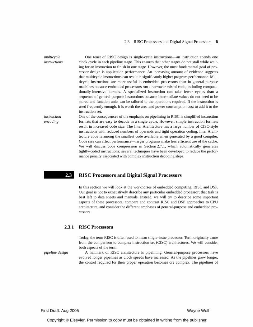
First Draft: Aug 2005 Wayne Wolf
Copyright © Elsevier. Permission to copy must be obtained in writing from the publisher
2.3 RISC Processors and Digital Signal Processors 6
multicycle instructions
One tenet of RISC design is single-cycle instructions—an instruction spends oneclock cycle in each pipeline stage. This ensures that other stages do not stall while wait-ing for an instruction to finish in one stage. However, the most fundamental goal of pro-cessor design is application performance. An increasing amount of evidence suggeststhat multicycle instructions can result in significantly higher program performance. Mul-ticycle instructions are more useful in embedded processors than in general-purposemachines because embedded processors run a narrower mix of code, including computa-tionally-intensive kernels. A specialized instruction can take fewer cycles than asequence of general-purpose instructions because intermediate values do not need to bestored and function units can be tailored to the operations required. If the instruction isused frequently enough, it is worth the area and power consumption cost to add it to theinstruction set.
instruction encoding
One of the consequences of the emphasis on pipelining in RISC is simplified instructionformats that are easy to decode in a single cycle. However, simple instruction formatsresult in increased code size. The Intel Architecture has a large number of CISC-styleinstructions with reduced numbers of operands and tight operation coding. Intel Archi-tecture code is among the smallest code available when generated by a good compiler.Code size can affect performance—larger programs make less efficient use of the cache.We will discuss code compression in Section 2.7.1, which automatically generatestightly-coded instructions; several techniques have been developed to reduce the perfor-mance penalty associated with complex instruction decoding steps.
RISC Processors and Digital Signal Processors
In this section we will look at the workhorses of embedded computing, RISC and DSP.Our goal is not to exhaustively describe any particular embedded processor; that task isbest left to data sheets and manuals. Instead, we will try to describe some importantaspects of these processors, compare and contrast RISC and DSP approaches to CPUarchitecture, and consider the different emphases of general-purpose and embedded pro-cessors.
2.3.1 RISC Processors
Today, the term RISC is often used to mean single-issue processor. Term originally camefrom the comparison to complex instruction set (CISC) architectures. We will considerboth aspects of the term.
pipeline design A hallmark of RISC architecture is pipelining. General-purpose processors haveevolved longer pipelines as clock speeds have increased. As the pipelines grow longer,the control required for their proper operation becomes ore complex. The pipelines of
2.3
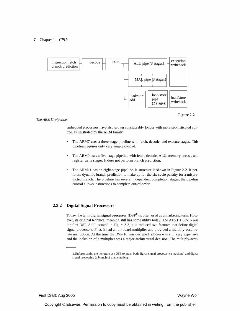
First Draft: Aug 2005 Wayne Wolf
Copyright © Elsevier. Permission to copy must be obtained in writing from the publisher
7 Chapter 1 CPUs
embedded processors have also grown considerably longer with more sophisticated con-trol, as illustrated by the ARM family:
• The ARM7 uses a three-stage pipeline with fetch, decode, and execute stages. Thispipeline requires only very simple control.
• The ARM9 uses a five-stage pipeline with fetch, decode, ALU, memory access, andregister write stages. It does not perform branch prediction.
• The ARM11 has an eight-stage pipeline. It structure is shown in Figure 2-2. It per-forms dynamic branch prediction to make up for the six cycle penalty for a mispre-dicted branch. The pipeline has several independent completion stages; the pipelinecontrol allows instructions to complete out-of-order.
2.3.2 Digital Signal Processors
Today, the term digital signal processor (DSP1) is often used as a marketing term. How-ever, its original technical meaning still has some utility today. The AT&T DSP-16 wasthe first DSP. As illustrated in Figure 2-3, it introduced two features that define digitalsignal processors. First, it had an on-board multiplier and provided a multiply-accumu-late instruction. At the time the DSP-16 was designed, silicon was still very expensiveand the inclusion of a multiplier was a major architectural decision. The multiply-accu-
instruction fetchbranch prediction
decode issue ALU pipe (3 stages)
MAC pipe (3 stages)
executionwriteback
load/storewriteback
load/storeadd
load/storepipe(2 stages)
Figure 2-2The ARM11 pipeline.
1.Unfortunately, the literature use DSP to mean both digital signal processor (a machine) and digitalsignal processing (a branch of mathematics).
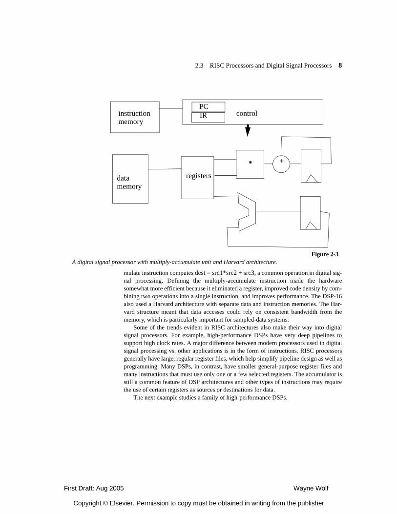
First Draft: Aug 2005 Wayne Wolf
Copyright © Elsevier. Permission to copy must be obtained in writing from the publisher
2.3 RISC Processors and Digital Signal Processors 8
mulate instruction computes dest = src1*src2 + src3, a common operation in digital sig-nal processing. Defining the multiply-accumulate instruction made the hardwaresomewhat more efficient because it eliminated a register, improved code density by com-bining two operations into a single instruction, and improves performance. The DSP-16also used a Harvard architecture with separate data and instruction memories. The Har-vard structure meant that data accesses could rely on consistent bandwidth from thememory, which is particularly important for sampled-data systems.
Some of the trends evident in RISC architectures also make their way into digitalsignal processors. For example, high-performance DSPs have very deep pipelines tosupport high clock rates. A major difference between modern processors used in digitalsignal processing vs. other applications is in the form of instructions. RISC processorsgenerally have large, regular register files, which help simplify pipeline design as well asprogramming. Many DSPs, in contrast, have smaller general-purpose register files andmany instructions that must use only one or a few selected registers. The accumulator isstill a common feature of DSP architectures and other types of instructions may requirethe use of certain registers as sources or destinations for data.
The next example studies a family of high-performance DSPs.
* +
registersdata memory
controlinstructionmemory
PCIR
Figure 2-3A digital signal processor with multiply-accumulate unit and Harvard architecture.
First Draft: Aug 2005 Wayne Wolf
Copyright © Elsevier. Permission to copy must be obtained in writing from the publisher
9 Chapter 1 CPUs
Application Example 2-1
The Texas Instruments C5x DSP familyThe C5x family [Tex01,Tex01B] is an architecture for high-performance signal pro-
cessing. The C5x supports several features:
• A 40-bit arithmetic unit, which may be interpreted as 32-bit values plus 8 guard bitsfor improved rounding control. The ALU can also be split to perform two 16-bitoperands.
• A barrel shifter performs arbitrary shifts for the ALU.
• A 17x17 multiplier and adder can perform multiply-accumulate operations.
• A comparison unit compares the high and low accumulator words to help accelerateViterbi encoding/decoding.
• A single-cycle exponent encoder can be used for wide-dynamic-range arithmetic.
• Two dedicated address generators.
The C5x includes a variety of registers:
• Status registers include flags for arithmetic results, processor status, etc.
• Auxiliary registers are used to generate 16-bit addresses.
• A temporary register can hold a multiplicand or a shift count.
• A transition register is used for Viterbi operations.
• The stack pointer holds the top of the system stack.
• A circular buffer size register is used for circular buffers common in signal process-ing.
• Block-repeat registers help implement block-repeat instructions.
• Interrupt registers provide the interface to the interrupt system.
The C5x family defines a variety of addressing modes. Some of them include:
• ARn mode performs indirect addressing through the auxiliary registers.
• DP mode performs direct addressing from the DP register.
• K23 mode uses an absolute address.
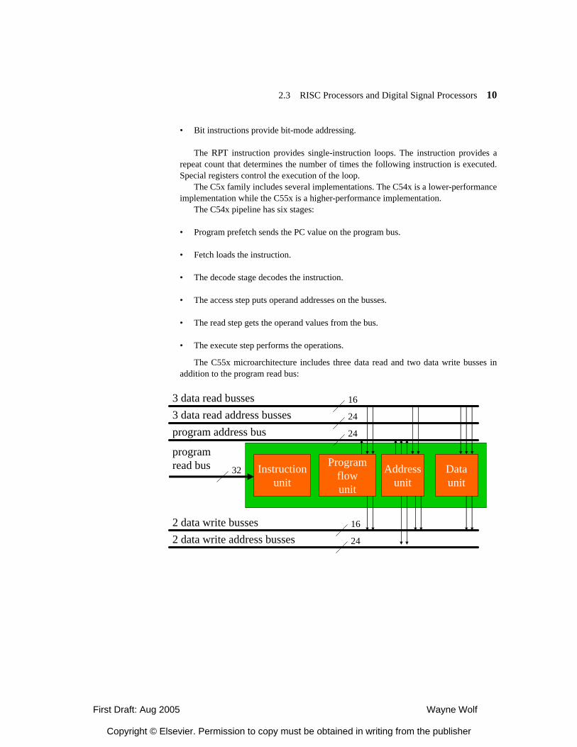
First Draft: Aug 2005 Wayne Wolf
Copyright © Elsevier. Permission to copy must be obtained in writing from the publisher
2.3 RISC Processors and Digital Signal Processors 10
• Bit instructions provide bit-mode addressing.
The RPT instruction provides single-instruction loops. The instruction provides arepeat count that determines the number of times the following instruction is executed.Special registers control the execution of the loop.
The C5x family includes several implementations. The C54x is a lower-performanceimplementation while the C55x is a higher-performance implementation.
The C54x pipeline has six stages:
• Program prefetch sends the PC value on the program bus.
• Fetch loads the instruction.
• The decode stage decodes the instruction.
• The access step puts operand addresses on the busses.
• The read step gets the operand values from the bus.
• The execute step performs the operations.
The C55x microarchitecture includes three data read and two data write busses inaddition to the program read bus:
Instructionunit
Programflowunit
Addressunit
Dataunit
3 data read busses3 data read address bussesprogram address bus
programread bus
2 data write busses2 data write address busses
16
24
24
16
24
32
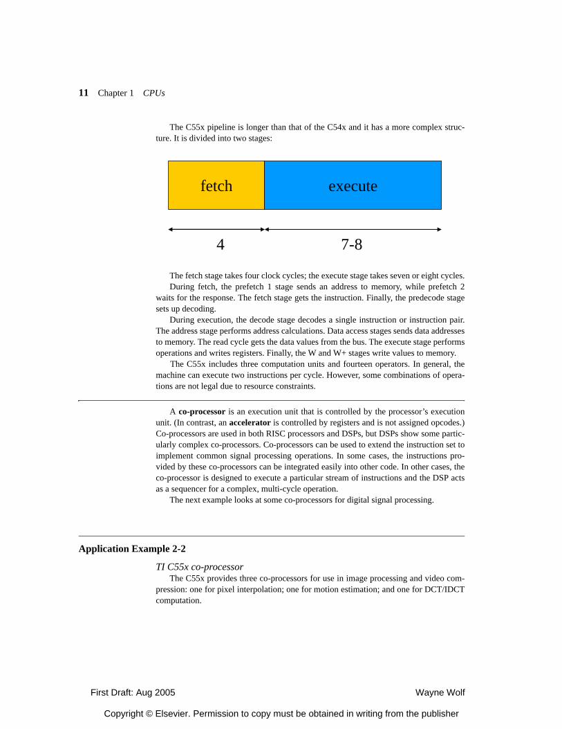
First Draft: Aug 2005 Wayne Wolf
Copyright © Elsevier. Permission to copy must be obtained in writing from the publisher
11 Chapter 1 CPUs
The C55x pipeline is longer than that of the C54x and it has a more complex struc-ture. It is divided into two stages:
The fetch stage takes four clock cycles; the execute stage takes seven or eight cycles.During fetch, the prefetch 1 stage sends an address to memory, while prefetch 2
waits for the response. The fetch stage gets the instruction. Finally, the predecode stagesets up decoding.
During execution, the decode stage decodes a single instruction or instruction pair.The address stage performs address calculations. Data access stages sends data addressesto memory. The read cycle gets the data values from the bus. The execute stage performsoperations and writes registers. Finally, the W and W+ stages write values to memory.
The C55x includes three computation units and fourteen operators. In general, themachine can execute two instructions per cycle. However, some combinations of opera-tions are not legal due to resource constraints.
A co-processor is an execution unit that is controlled by the processor’s executionunit. (In contrast, an accelerator is controlled by registers and is not assigned opcodes.)Co-processors are used in both RISC processors and DSPs, but DSPs show some partic-ularly complex co-processors. Co-processors can be used to extend the instruction set toimplement common signal processing operations. In some cases, the instructions pro-vided by these co-processors can be integrated easily into other code. In other cases, theco-processor is designed to execute a particular stream of instructions and the DSP actsas a sequencer for a complex, multi-cycle operation.
The next example looks at some co-processors for digital signal processing.
Application Example 2-2
TI C55x co-processorThe C55x provides three co-processors for use in image processing and video com-
pression: one for pixel interpolation; one for motion estimation; and one for DCT/IDCTcomputation.
fetch execute
4 7-8
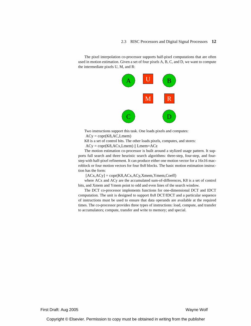
First Draft: Aug 2005 Wayne Wolf
Copyright © Elsevier. Permission to copy must be obtained in writing from the publisher
2.3 RISC Processors and Digital Signal Processors 12
The pixel interpolation co-processor supports half-pixel computations that are oftenused in motion estimation. Given a set of four pixels A, B, C, and D, we want to computethe intermediate pixels U, M, and R:
Two instructions support this task. One loads pixels and computes:ACy = copr(K8,AC,Lmem)
K8 is a set of control bits. The other loads pixels, computes, and stores:ACy = copr(K8,ACx,Lmem) || Lmem=ACz
The motion estimation co-processor is built around a stylized usage pattern. It sup-ports full search and three heuristic search algorithms: three-step, four-step, and four-step with half-pixel refinement. It can produce either one motion vector for a 16x16 mac-roblock or four motion vectors for four 8x8 blocks. The basic motion estimation instruc-tion has the form:
[ACx,ACy] = copr(K8,ACx,ACy,Xmem,Ymem,Coeff)where ACx and ACy are the accumulated sum-of-differences, K8 is a set of control
bits, and Xmem and Ymem point to odd and even lines of the search window.The DCT co-processor implements functions for one-dimensional DCT and IDCT
computation. The unit is designed to support 8x8 DCT/IDCT and a particular sequenceof instructions must be used to ensure that data operands are available at the requiredtimes. The co-processor provides three types of instructions: load, compute, and transferto accumulators; compute, transfer and write to memory; and special.
A B
C D
U
M R
U
M R
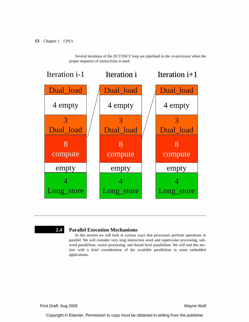
First Draft: Aug 2005 Wayne Wolf
Copyright © Elsevier. Permission to copy must be obtained in writing from the publisher
13 Chapter 1 CPUs
Several iterations of the DCT/IDCT loop are pipelined in the co-processor when theproper sequence of instructions is used:
Parallel Execution MechanismsIn this section we will look at various ways that processors perform operations in
parallel. We will consider very long instruction word and superscalar processing, sub-word parallelism, vector processing, and thread level parallelism. We will end this sec-tion with a brief consideration of the available parallelism in some embeddedapplications.
Iteration i-1
Dual_load
8compute
4Long_store
4 empty
3Dual_load
empty
Iteration i
Dual_load
8compute
4Long_store
4 empty
3Dual_load
empty
Iteration i
Dual_load
8compute
4Long_store
4 empty
3Dual_load
empty
Iteration i+1
Dual_load
8compute
4Long_store
4 empty
3Dual_load
empty
Iteration i+1
Dual_load
8compute
4Long_store
4 empty
3Dual_load
empty
2.4
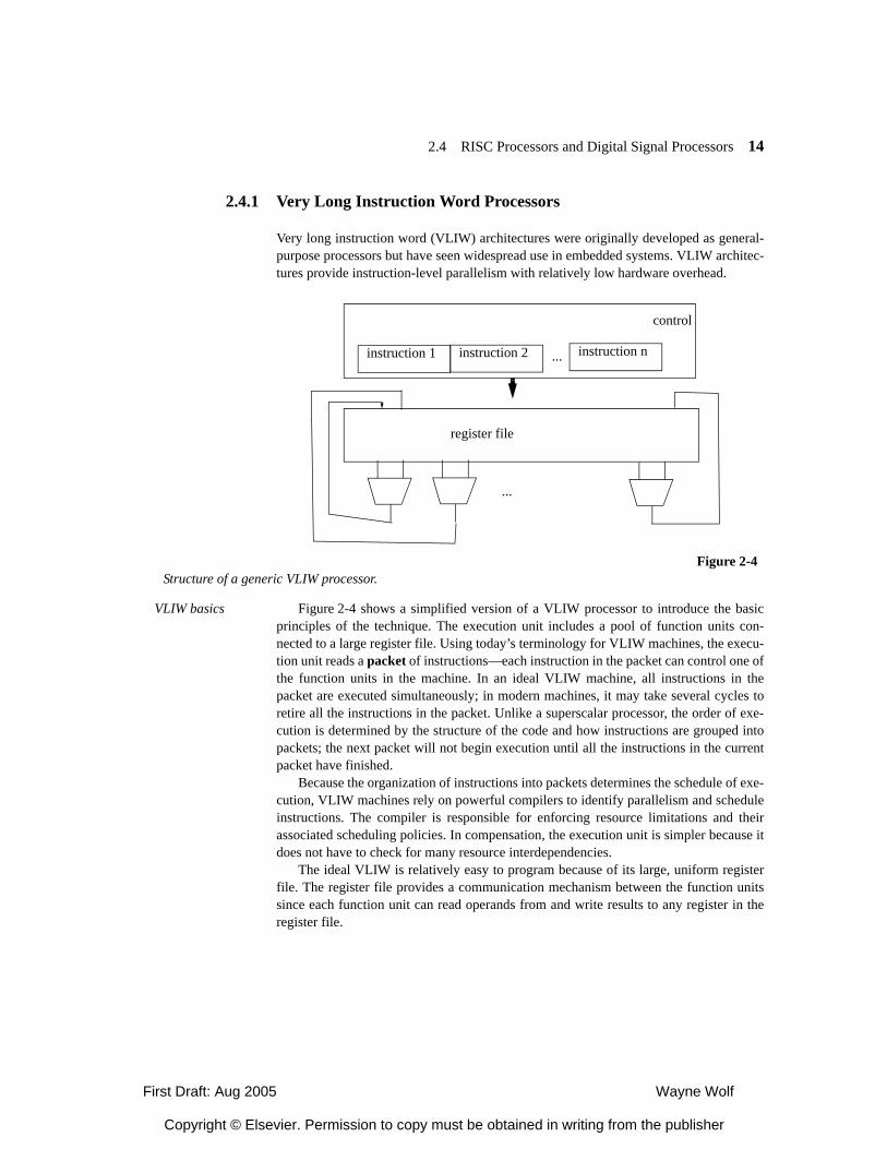
First Draft: Aug 2005 Wayne Wolf
Copyright © Elsevier. Permission to copy must be obtained in writing from the publisher
2.4 RISC Processors and Digital Signal Processors 14
2.4.1 Very Long Instruction Word Processors
Very long instruction word (VLIW) architectures were originally developed as general-purpose processors but have seen widespread use in embedded systems. VLIW architec-tures provide instruction-level parallelism with relatively low hardware overhead.
VLIW basics Figure 2-4 shows a simplified version of a VLIW processor to introduce the basicprinciples of the technique. The execution unit includes a pool of function units con-nected to a large register file. Using today’s terminology for VLIW machines, the execu-tion unit reads a packet of instructions—each instruction in the packet can control one ofthe function units in the machine. In an ideal VLIW machine, all instructions in thepacket are executed simultaneously; in modern machines, it may take several cycles toretire all the instructions in the packet. Unlike a superscalar processor, the order of exe-cution is determined by the structure of the code and how instructions are grouped intopackets; the next packet will not begin execution until all the instructions in the currentpacket have finished.
Because the organization of instructions into packets determines the schedule of exe-cution, VLIW machines rely on powerful compilers to identify parallelism and scheduleinstructions. The compiler is responsible for enforcing resource limitations and theirassociated scheduling policies. In compensation, the execution unit is simpler because itdoes not have to check for many resource interdependencies.
The ideal VLIW is relatively easy to program because of its large, uniform registerfile. The register file provides a communication mechanism between the function unitssince each function unit can read operands from and write results to any register in theregister file.
...
register file
control
instruction 1 instruction 2 instruction n...
Figure 2-4Structure of a generic VLIW processor.
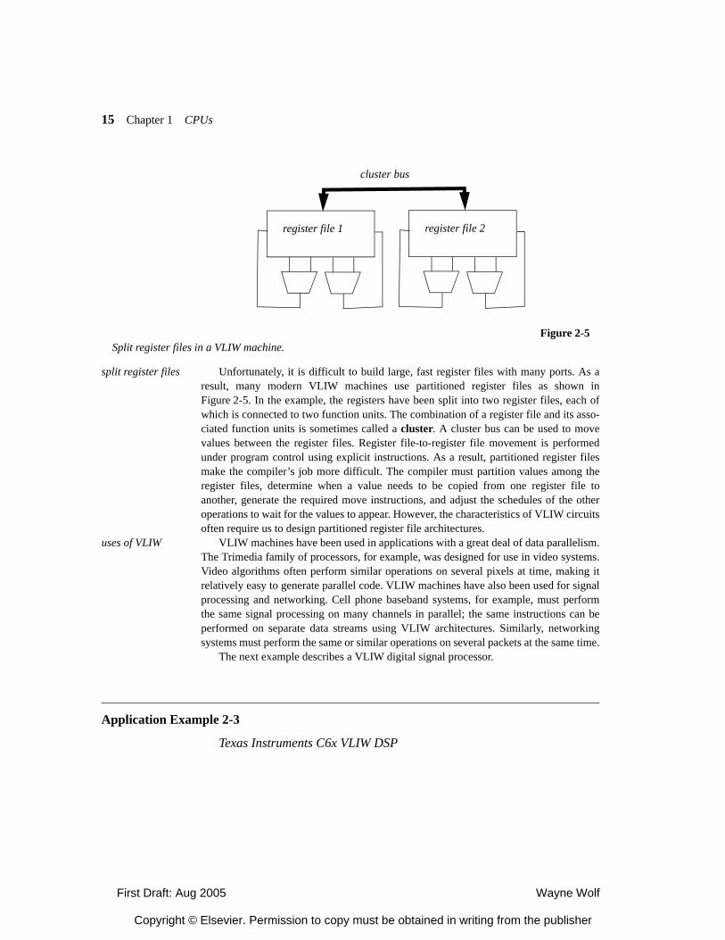
First Draft: Aug 2005 Wayne Wolf
Copyright © Elsevier. Permission to copy must be obtained in writing from the publisher
15 Chapter 1 CPUs
split register files Unfortunately, it is difficult to build large, fast register files with many ports. As aresult, many modern VLIW machines use partitioned register files as shown inFigure 2-5. In the example, the registers have been split into two register files, each ofwhich is connected to two function units. The combination of a register file and its asso-ciated function units is sometimes called a cluster. A cluster bus can be used to movevalues between the register files. Register file-to-register file movement is performedunder program control using explicit instructions. As a result, partitioned register filesmake the compiler’s job more difficult. The compiler must partition values among theregister files, determine when a value needs to be copied from one register file toanother, generate the required move instructions, and adjust the schedules of the otheroperations to wait for the values to appear. However, the characteristics of VLIW circuitsoften require us to design partitioned register file architectures.
uses of VLIW VLIW machines have been used in applications with a great deal of data parallelism.The Trimedia family of processors, for example, was designed for use in video systems.Video algorithms often perform similar operations on several pixels at time, making itrelatively easy to generate parallel code. VLIW machines have also been used for signalprocessing and networking. Cell phone baseband systems, for example, must performthe same signal processing on many channels in parallel; the same instructions can beperformed on separate data streams using VLIW architectures. Similarly, networkingsystems must perform the same or similar operations on several packets at the same time.
The next example describes a VLIW digital signal processor.
Application Example 2-3
Texas Instruments C6x VLIW DSP
Figure 2-5Split register files in a VLIW machine.
register file 1 register file 2
cluster bus
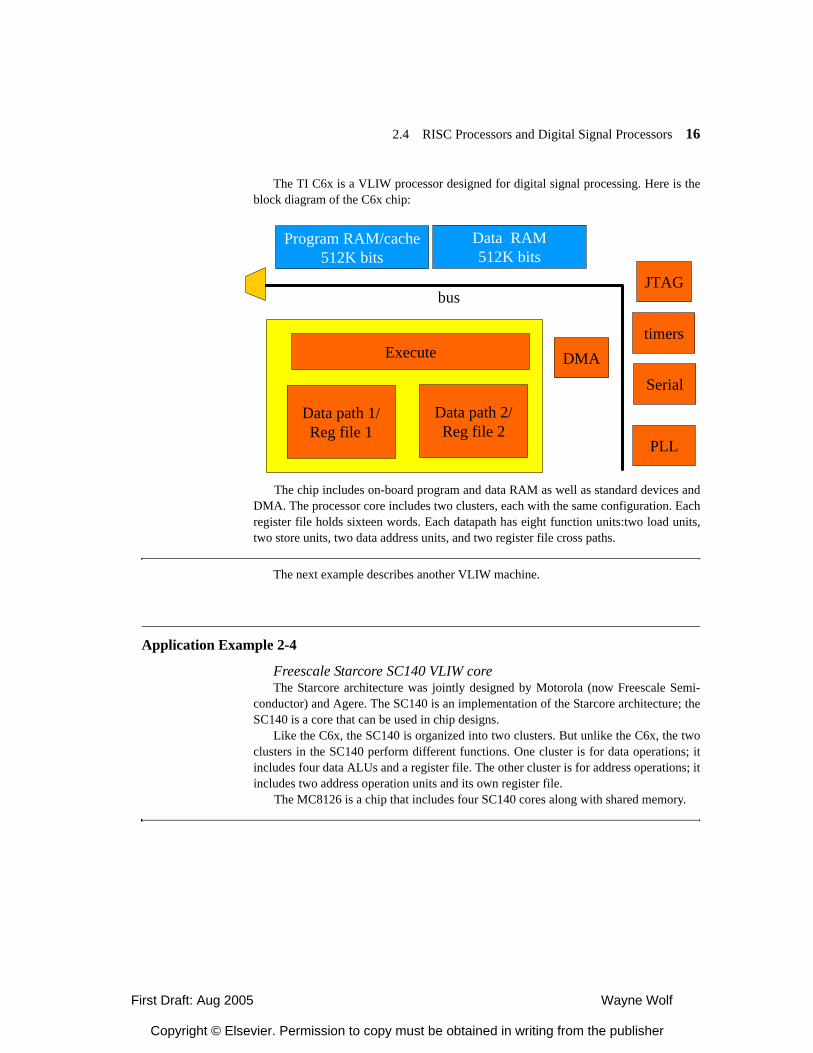
First Draft: Aug 2005 Wayne Wolf
Copyright © Elsevier. Permission to copy must be obtained in writing from the publisher
2.4 RISC Processors and Digital Signal Processors 16
The TI C6x is a VLIW processor designed for digital signal processing. Here is theblock diagram of the C6x chip:
The chip includes on-board program and data RAM as well as standard devices andDMA. The processor core includes two clusters, each with the same configuration. Eachregister file holds sixteen words. Each datapath has eight function units:two load units,two store units, two data address units, and two register file cross paths.
The next example describes another VLIW machine.
Application Example 2-4
Freescale Starcore SC140 VLIW coreThe Starcore architecture was jointly designed by Motorola (now Freescale Semi-
conductor) and Agere. The SC140 is an implementation of the Starcore architecture; theSC140 is a core that can be used in chip designs.
Like the C6x, the SC140 is organized into two clusters. But unlike the C6x, the twoclusters in the SC140 perform different functions. One cluster is for data operations; itincludes four data ALUs and a register file. The other cluster is for address operations; itincludes two address operation units and its own register file.
The MC8126 is a chip that includes four SC140 cores along with shared memory.
Data path 1/Reg file 1
Data path 2/Reg file 2
Execute DMAtimers
Serial
Program RAM/cache512K bits
Data RAM512K bits
JTAG
PLL
bus
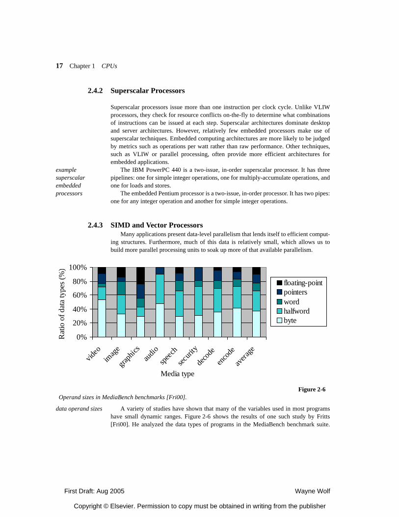
First Draft: Aug 2005 Wayne Wolf
Copyright © Elsevier. Permission to copy must be obtained in writing from the publisher
17 Chapter 1 CPUs
2.4.2 Superscalar Processors
Superscalar processors issue more than one instruction per clock cycle. Unlike VLIWprocessors, they check for resource conflicts on-the-fly to determine what combinationsof instructions can be issued at each step. Superscalar architectures dominate desktopand server architectures. However, relatively few embedded processors make use ofsuperscalar techniques. Embedded computing architectures are more likely to be judgedby metrics such as operations per watt rather than raw performance. Other techniques,such as VLIW or parallel processing, often provide more efficient architectures forembedded applications.
example superscalar embedded processors
The IBM PowerPC 440 is a two-issue, in-order superscalar processor. It has threepipelines: one for simple integer operations, one for multiply-accumulate operations, andone for loads and stores.
The embedded Pentium processor is a two-issue, in-order processor. It has two pipes:one for any integer operation and another for simple integer operations.
2.4.3 SIMD and Vector ProcessorsMany applications present data-level parallelism that lends itself to efficient comput-
ing structures. Furthermore, much of this data is relatively small, which allows us tobuild more parallel processing units to soak up more of that available parallelism.
data operand sizes A variety of studies have shown that many of the variables used in most programshave small dynamic ranges. Figure 2-6 shows the results of one such study by Fritts[Fri00]. He analyzed the data types of programs in the MediaBench benchmark suite.
0%
20%
40%
60%
80%
100%
video
imag
e
graph
icsau
dio
speec
h
securi
ty
deco
deen
code
avera
ge
Media type
Rat
io o
f dat
a ty
pes (
%)
floating-pointpointerswordhalfwordbyte
Figure 2-6Operand sizes in MediaBench benchmarks [Fri00].
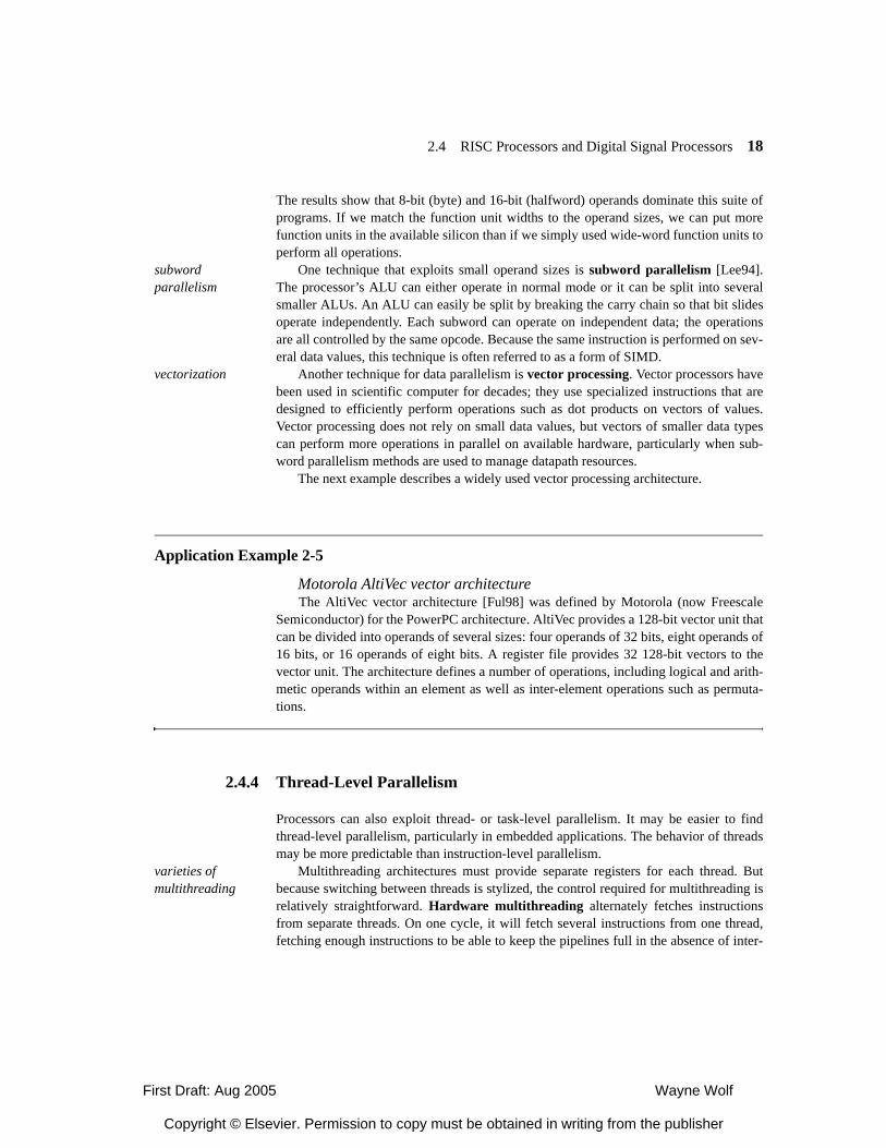
First Draft: Aug 2005 Wayne Wolf
Copyright © Elsevier. Permission to copy must be obtained in writing from the publisher
2.4 RISC Processors and Digital Signal Processors 18
The results show that 8-bit (byte) and 16-bit (halfword) operands dominate this suite ofprograms. If we match the function unit widths to the operand sizes, we can put morefunction units in the available silicon than if we simply used wide-word function units toperform all operations.
subword parallelism
One technique that exploits small operand sizes is subword parallelism [Lee94].The processor’s ALU can either operate in normal mode or it can be split into severalsmaller ALUs. An ALU can easily be split by breaking the carry chain so that bit slidesoperate independently. Each subword can operate on independent data; the operationsare all controlled by the same opcode. Because the same instruction is performed on sev-eral data values, this technique is often referred to as a form of SIMD.
vectorization Another technique for data parallelism is vector processing. Vector processors havebeen used in scientific computer for decades; they use specialized instructions that aredesigned to efficiently perform operations such as dot products on vectors of values.Vector processing does not rely on small data values, but vectors of smaller data typescan perform more operations in parallel on available hardware, particularly when sub-word parallelism methods are used to manage datapath resources.
The next example describes a widely used vector processing architecture.
Application Example 2-5
Motorola AltiVec vector architectureThe AltiVec vector architecture [Ful98] was defined by Motorola (now Freescale
Semiconductor) for the PowerPC architecture. AltiVec provides a 128-bit vector unit thatcan be divided into operands of several sizes: four operands of 32 bits, eight operands of16 bits, or 16 operands of eight bits. A register file provides 32 128-bit vectors to thevector unit. The architecture defines a number of operations, including logical and arith-metic operands within an element as well as inter-element operations such as permuta-tions.
2.4.4 Thread-Level Parallelism
Processors can also exploit thread- or task-level parallelism. It may be easier to findthread-level parallelism, particularly in embedded applications. The behavior of threadsmay be more predictable than instruction-level parallelism.
varieties of multithreading
Multithreading architectures must provide separate registers for each thread. Butbecause switching between threads is stylized, the control required for multithreading isrelatively straightforward. Hardware multithreading alternately fetches instructionsfrom separate threads. On one cycle, it will fetch several instructions from one thread,fetching enough instructions to be able to keep the pipelines full in the absence of inter-
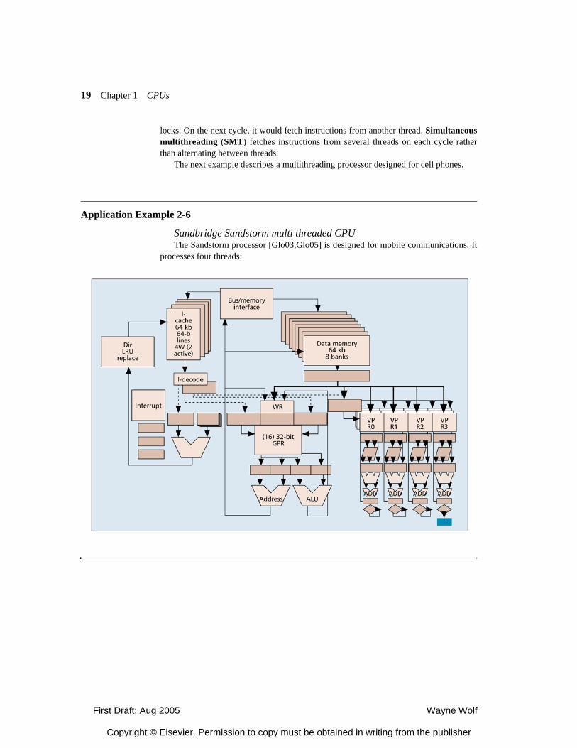
First Draft: Aug 2005 Wayne Wolf
Copyright © Elsevier. Permission to copy must be obtained in writing from the publisher
19 Chapter 1 CPUs
locks. On the next cycle, it would fetch instructions from another thread. Simultaneousmultithreading (SMT) fetches instructions from several threads on each cycle ratherthan alternating between threads.
The next example describes a multithreading processor designed for cell phones.
Application Example 2-6
Sandbridge Sandstorm multi threaded CPUThe Sandstorm processor [Glo03,Glo05] is designed for mobile communications. It
processes four threads:
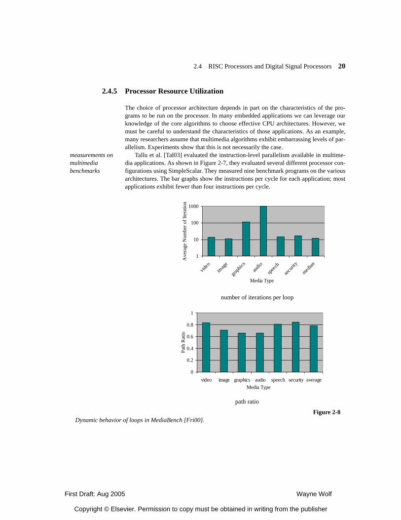
First Draft: Aug 2005 Wayne Wolf
Copyright © Elsevier. Permission to copy must be obtained in writing from the publisher
2.4 RISC Processors and Digital Signal Processors 20
2.4.5 Processor Resource Utilization
The choice of processor architecture depends in part on the characteristics of the pro-grams to be run on the processor. In many embedded applications we can leverage ourknowledge of the core algorithms to choose effective CPU architectures. However, wemust be careful to understand the characteristics of those applications. As an example,many researchers assume that multimedia algorithms exhibit embarrassing levels of par-allelism. Experiments show that this is not necessarily the case.
measurements on multimedia benchmarks
Tallu et al. [Tal03] evaluated the instruction-level parallelism available in multime-dia applications. As shown in Figure 2-7, they evaluated several different processor con-figurations using SimpleScalar. They measured nine benchmark programs on the variousarchitectures. The bar graphs show the instructions per cycle for each application; mostapplications exhibit fewer than four instructions per cycle.
1
10
100
1000
video
imag
e
graph
icsau
dio
speec
h
securi
ty
median
Media Type
Ave
rage
Num
ber o
f Ite
ratio
ns
number of iterations per loop
0
0.2
0.4
0.6
0.8
1
video image graphics audio speech security averageMedia Type
Path
Rat
io
path ratio
Figure 2-8Dynamic behavior of loops in MediaBench [Fri00].
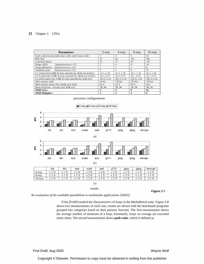
First Draft: Aug 2005 Wayne Wolf
Copyright © Elsevier. Permission to copy must be obtained in writing from the publisher
21 Chapter 1 CPUs
Fritts [Fri00] studied the characteristics of loops in the MediaBench suite. Figure 2-8shows two measurements; in each case, results are shown with the benchmark programsgrouped into categories based on their primary function. The first measurement showsthe average number of iterations of a loop; fortunately, loops on average are executedmany times. The second measurement shows path ratio, which is defined as
processor configurations
resultsFigure 2-7
An evaluation of the available parallelism in multimedia applications [Tal03].
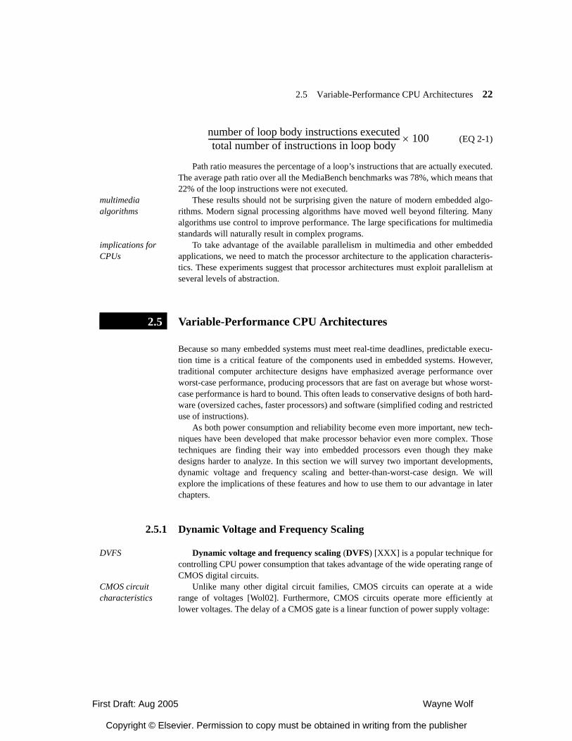
First Draft: Aug 2005 Wayne Wolf
Copyright © Elsevier. Permission to copy must be obtained in writing from the publisher
2.5 Variable-Performance CPU Architectures 22
(EQ 2-1)
Path ratio measures the percentage of a loop’s instructions that are actually executed.The average path ratio over all the MediaBench benchmarks was 78%, which means that22% of the loop instructions were not executed.
multimedia algorithms
These results should not be surprising given the nature of modern embedded algo-rithms. Modern signal processing algorithms have moved well beyond filtering. Manyalgorithms use control to improve performance. The large specifications for multimediastandards will naturally result in complex programs.
implications for CPUs
To take advantage of the available parallelism in multimedia and other embeddedapplications, we need to match the processor architecture to the application characteris-tics. These experiments suggest that processor architectures must exploit parallelism atseveral levels of abstraction.
Variable-Performance CPU Architectures
Because so many embedded systems must meet real-time deadlines, predictable execu-tion time is a critical feature of the components used in embedded systems. However,traditional computer architecture designs have emphasized average performance overworst-case performance, producing processors that are fast on average but whose worst-case performance is hard to bound. This often leads to conservative designs of both hard-ware (oversized caches, faster processors) and software (simplified coding and restricteduse of instructions).
As both power consumption and reliability become even more important, new tech-niques have been developed that make processor behavior even more complex. Thosetechniques are finding their way into embedded processors even though they makedesigns harder to analyze. In this section we will survey two important developments,dynamic voltage and frequency scaling and better-than-worst-case design. We willexplore the implications of these features and how to use them to our advantage in laterchapters.
2.5.1 Dynamic Voltage and Frequency Scaling
DVFS Dynamic voltage and frequency scaling (DVFS) [XXX] is a popular technique forcontrolling CPU power consumption that takes advantage of the wide operating range ofCMOS digital circuits.
CMOS circuit characteristics
Unlike many other digital circuit families, CMOS circuits can operate at a widerange of voltages [Wol02]. Furthermore, CMOS circuits operate more efficiently atlower voltages. The delay of a CMOS gate is a linear function of power supply voltage:
number of loop body instructions executedtotal number of instructions in loop body------------------------------------------------------------------------------------------------------ 100×
2.5
First Draft: Aug 2005 Wayne Wolf
Copyright © Elsevier. Permission to copy must be obtained in writing from the publisher
23 Chapter 1 CPUs
, (EQ 2-2)
where the effective resistance of the MOS transistor is largely a linear function ofpower supply voltage. The energy consumed during operation of the gate is proportionalto the square of the operating voltage:
. (EQ 2-3)
The speed-power product for CMOS (ignoring leakage) is also CV2. Therefore, bylowering the power supply voltage, we can reduce energy consumption by V2 whilereducing performance by only V.
Because we can operate CMOS logic at many different points, a CPU can be oper-ated across a design space. Figure 2-9 illustrates the relationship between power supplyvoltage (V), operating speed (T), and power (P).
DVFS architecture An architecture for dynamic voltage and frequency scaling operates the CPU withinthis space under a control algorithm. Figure 2-10 shows the architecture of a DVFSarchitecture. The clock and power supply are generated by circuits that can supply arange of values; these circuits generally operate at discrete points rather than continu-ously-varying values. Both the clock generator and voltage generator are operated by acontroller that determines when the clock frequency and voltage will change and by howmuch.
DVFS control strategy
A DVFS controller must operate under constraints in order to optimize a design met-ric. The constraints are related to clock speed and power supply voltage: not only theirminimum and maximum values, but how quickly clock speed or power supply voltage
tp 2.2RC=
E CV2=
Figure 2-9The voltage/speed/power operating space.
V
T
P draw a better graph
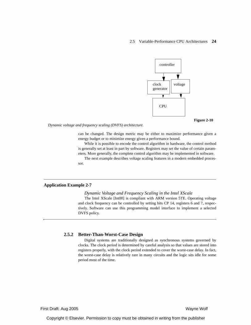
First Draft: Aug 2005 Wayne Wolf
Copyright © Elsevier. Permission to copy must be obtained in writing from the publisher
2.5 Variable-Performance CPU Architectures 24
can be changed. The design metric may be either to maximize performance given aenergy budget or to minimize energy given a performance bound.
While it is possible to encode the control algorithm in hardware, the control methodis generally set at least in part by software. Registers may set the value of certain param-eters. More generally, the complete control algorithm may be implemented in software.
The next example describes voltage scaling features in a modern embedded proces-sor.
Application Example 2-7
Dynamic Voltage and Frequency Scaling in the Intel XScaleThe Intel XScale [Int00] is compliant with ARM version 5TE. Operating voltage
and clock frequency can be controlled by setting bits CP 14, registers 6 and 7, respec-tively. Software can use this programming model interface to implement a selectedDVFS policy.
2.5.2 Better-Than-Worst-Case DesignDigital systems are traditionally designed as synchronous systems governed by
clocks. The clock period is determined by careful analysis so that values are stored intoregisters properly, with the clock period extended to cover the worst-case delay. In fact,the worst-case delay is relatively rare in many circuits and the logic sits idle for someperiod most of the time.
CPU
voltageclockgenerator
controller
Figure 2-10Dynamic voltage and frequency scaling (DVFS) architecture.
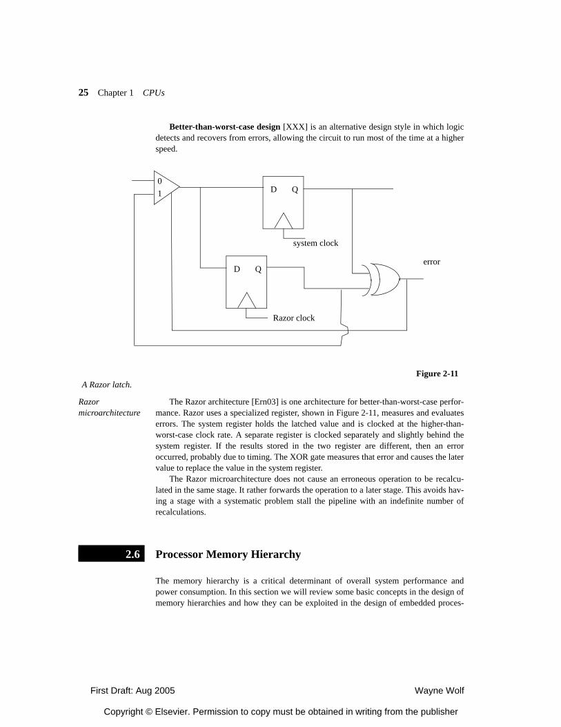
First Draft: Aug 2005 Wayne Wolf
Copyright © Elsevier. Permission to copy must be obtained in writing from the publisher
25 Chapter 1 CPUs
Better-than-worst-case design [XXX] is an alternative design style in which logicdetects and recovers from errors, allowing the circuit to run most of the time at a higherspeed.
Razor microarchitecture
The Razor architecture [Ern03] is one architecture for better-than-worst-case perfor-mance. Razor uses a specialized register, shown in Figure 2-11, measures and evaluateserrors. The system register holds the latched value and is clocked at the higher-than-worst-case clock rate. A separate register is clocked separately and slightly behind thesystem register. If the results stored in the two register are different, then an erroroccurred, probably due to timing. The XOR gate measures that error and causes the latervalue to replace the value in the system register.
The Razor microarchitecture does not cause an erroneous operation to be recalcu-lated in the same stage. It rather forwards the operation to a later stage. This avoids hav-ing a stage with a systematic problem stall the pipeline with an indefinite number ofrecalculations.
Processor Memory Hierarchy
The memory hierarchy is a critical determinant of overall system performance andpower consumption. In this section we will review some basic concepts in the design ofmemory hierarchies and how they can be exploited in the design of embedded proces-
Figure 2-11A Razor latch.
D Q
D Q
system clock
Razor clock
error
01
2.6
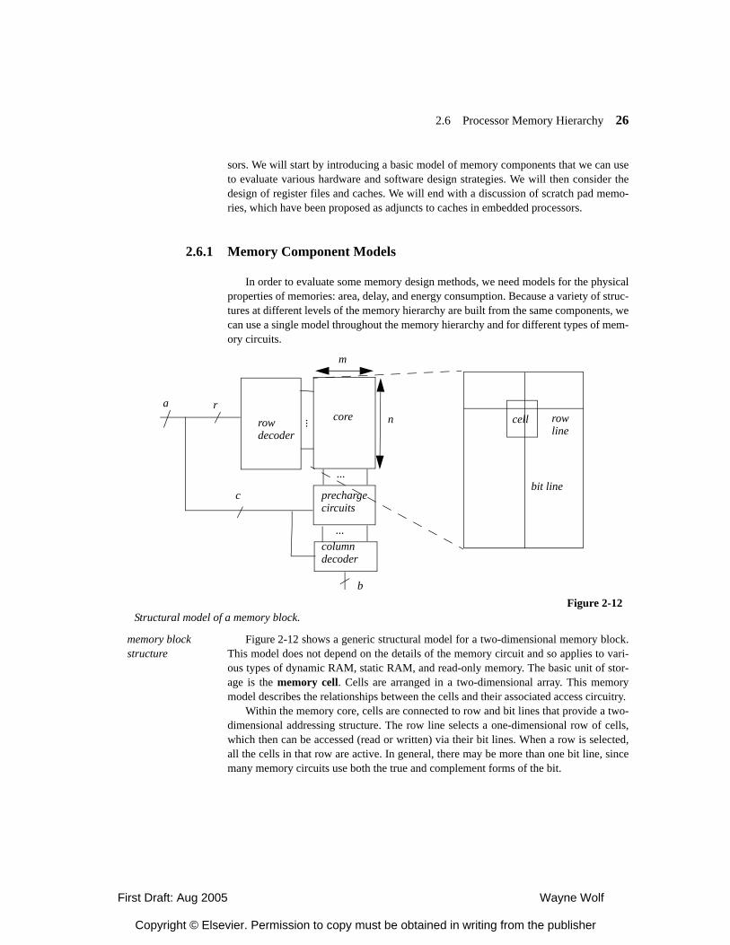
First Draft: Aug 2005 Wayne Wolf
Copyright © Elsevier. Permission to copy must be obtained in writing from the publisher
2.6 Processor Memory Hierarchy 26
sors. We will start by introducing a basic model of memory components that we can useto evaluate various hardware and software design strategies. We will then consider thedesign of register files and caches. We will end with a discussion of scratch pad memo-ries, which have been proposed as adjuncts to caches in embedded processors.
2.6.1 Memory Component Models
In order to evaluate some memory design methods, we need models for the physicalproperties of memories: area, delay, and energy consumption. Because a variety of struc-tures at different levels of the memory hierarchy are built from the same components, wecan use a single model throughout the memory hierarchy and for different types of mem-ory circuits.
memory block structure
Figure 2-12 shows a generic structural model for a two-dimensional memory block.This model does not depend on the details of the memory circuit and so applies to vari-ous types of dynamic RAM, static RAM, and read-only memory. The basic unit of stor-age is the memory cell. Cells are arranged in a two-dimensional array. This memorymodel describes the relationships between the cells and their associated access circuitry.
Within the memory core, cells are connected to row and bit lines that provide a two-dimensional addressing structure. The row line selects a one-dimensional row of cells,which then can be accessed (read or written) via their bit lines. When a row is selected,all the cells in that row are active. In general, there may be more than one bit line, sincemany memory circuits use both the true and complement forms of the bit.
corerowdecoder
...
prechargecircuits
columndecoder
...
...
m
n cell
bit line
rowline
b
a r
c
Figure 2-12Structural model of a memory block.
First Draft: Aug 2005 Wayne Wolf
Copyright © Elsevier. Permission to copy must be obtained in writing from the publisher
27 Chapter 1 CPUs
The row decoder circuitry is a demultiplexer that drives one of the n row lines in thecore by decoding the r bits of row address. A column decoder selects a b-bit wide subsetof the bit lines based upon the c bits of column address. Some memories also require pre-charge circuits to control the bit lines.
area model The area model of the memory block has components for the elements of the blockmodel:
(EQ 2-4)
The row decoder area is
, (EQ 2-5)
where ar is the area of a one-bit slice of the row decoder. The core area is
, (EQ 2-6)
where ax is the area of a one-bit core cell, including its share of the row and bit lines. The precharge circuit area is
, (EQ 2-7)
where ap is the area of a one-bit slice of the precharge circuit. The column decoder area is
, (EQ 2-8)
where ac is the area of a one-bit slice of the column decoder.delay model The delay model of the memory block follows the flow of information in a memory
access. Some of its elements are independent of m and n while others depend on thelength of the row or column lines in the cell:
. (EQ 2-9)
is the time required for the precharge circuitry. It is generally independent ofthe number of columns but may depend on the number of rows due to the time requiredto precharge the bit line. is the row decoder time, including the row line propagationtime. The delay through the decoding logic generally depends upon the value of m butthe dependence may vary due to the type of decoding circuit used. is the reactiontime of the core cell itself. is the time required for the values to propagate throughthe bit line. is the delay through the column decoder, which once again may dependon the value of n.
A Ar Ax Ap Ac+ + +=
Ar arn=
Ax axmn=
Ap apn=
Ac acn=
∆ ∆setup ∆r ∆x ∆bit ∆c+ + + +=
∆setup
∆
∆x∆bit
∆c
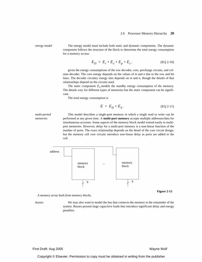
First Draft: Aug 2005 Wayne Wolf
Copyright © Elsevier. Permission to copy must be obtained in writing from the publisher
2.6 Processor Memory Hierarchy 28
energy model The energy model must include both static and dynamic components. The dynamiccomponent follows the structure of the block to determine the total energy consumptionfor a memory access:
, (EQ 2-10)
given the energy consumptions of the row decoder, core, precharge circuits, and col-umn decoder. The core energy depends on the values of m and n due to the row and bitlines. The decoder circuitry energy also depends on m and n, though the details of thatrelationships depend on the circuits used.
The static component models the standby energy consumption of the memory.The details vary for different types of memories but the static component can be signifi-cant.
The total energy consumption is
. (EQ 2-11)
multi-ported memories
This model describes a single-port memory in which a single read or write can beperformed at any given time. A multi-port memory accepts multiple addresses/data forsimultaneous accesses. Some aspects of the memory block model extend easily to multi-port memories. However, delay for a multi-port memory is a non-linear function of thenumber of ports. The exact relationship depends on the detail of the core circuit design,but the memory cell core circuits introduce non-linear delay as ports are added to thecell.
busses We may also want to model the bus that connects the memory to the remainder of thesystem. Busses present large capacitive loads that introduce significant delay and energypenalties.
ED Er Ex Ep Ec+ + +=
ES
E ED ES+=
memoryblock
memoryblock
...
b b
Figure 2-13A memory array built from memory blocks.
address
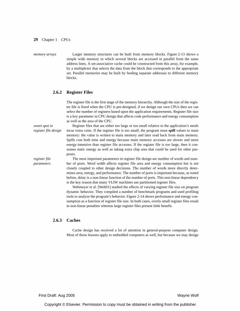
First Draft: Aug 2005 Wayne Wolf
Copyright © Elsevier. Permission to copy must be obtained in writing from the publisher
29 Chapter 1 CPUs
memory arrays Larger memory structures can be built from memory blocks. Figure 2-13 shows asimple wide memory in which several blocks are accessed in parallel from the sameaddress lines. A set-associative cache could be constructed from this array, for example,by a multiplexer that selects the data from the block that corresponds to the appropriateset. Parallel memories may be built by feeding separate addresses to different memoryblocks.
2.6.2 Register Files
The register file is the first stage of the memory hierarchy. Although the size of the regis-ter file is fixed when the CPU is pre-designed, if we design our own CPUs then we canselect the number of registers based upon the application requirements. Register file sizeis a key parameter in CPU design that affects code performance and energy consumptionas well as the area of the CPU.
sweet spot in register file design
Register files that are either too large or too small relative to the application’s needsincur extra costs. If the register file is too small, the program must spill values to mainmemory: the value is written to main memory and later read back from main memory.Spills cost both time and energy because main memory accesses are slower and moreenergy-intensive than register file accesses. If the register file is too large, then it con-sumes static energy as well as taking extra chip area that could be used for other pur-poses.
register file parameters
The most important parameters in register file design are number of words and num-ber of ports. Word width affects register file area and energy consumption but is notclosely coupled to other design decisions. The number of words more directly deter-mines area, energy, and performance. The number of ports is important because, as notedbefore, delay is a non-linear function of the number of ports. This non-linear dependencyis the key reason that many VLIW machines use partitioned register files.
Wehmeyer et al. [Weh01] studied the effects of varying register file size on programdynamic behavior. They compiled a number of benchmark programs and used profilingtools to analyze the program’s behavior. Figure 2-14 shows performance and energy con-sumption as a function of register file size. In both cases, overly small register files resultin non-linear penalties whereas large register files present little benefit.
2.6.3 Caches
Cache design has received a lot of attention in general-purpose computer design.Most of those lessons apply to embedded computers as well, but because we may design
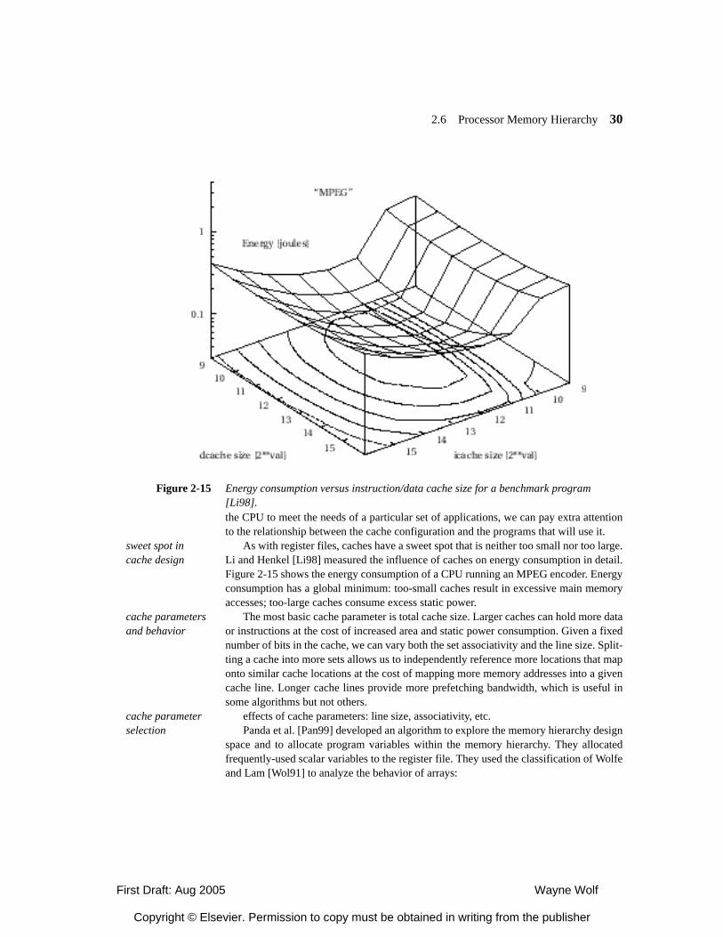
First Draft: Aug 2005 Wayne Wolf
Copyright © Elsevier. Permission to copy must be obtained in writing from the publisher
2.6 Processor Memory Hierarchy 30
the CPU to meet the needs of a particular set of applications, we can pay extra attentionto the relationship between the cache configuration and the programs that will use it.
sweet spot in cache design
As with register files, caches have a sweet spot that is neither too small nor too large.Li and Henkel [Li98] measured the influence of caches on energy consumption in detail.Figure 2-15 shows the energy consumption of a CPU running an MPEG encoder. Energyconsumption has a global minimum: too-small caches result in excessive main memoryaccesses; too-large caches consume excess static power.
cache parameters and behavior
The most basic cache parameter is total cache size. Larger caches can hold more dataor instructions at the cost of increased area and static power consumption. Given a fixednumber of bits in the cache, we can vary both the set associativity and the line size. Split-ting a cache into more sets allows us to independently reference more locations that maponto similar cache locations at the cost of mapping more memory addresses into a givencache line. Longer cache lines provide more prefetching bandwidth, which is useful insome algorithms but not others.
cache parameter selection
effects of cache parameters: line size, associativity, etc.Panda et al. [Pan99] developed an algorithm to explore the memory hierarchy design
space and to allocate program variables within the memory hierarchy. They allocatedfrequently-used scalar variables to the register file. They used the classification of Wolfeand Lam [Wol91] to analyze the behavior of arrays:
Figure 2-15 Energy consumption versus instruction/data cache size for a benchmark program [Li98].
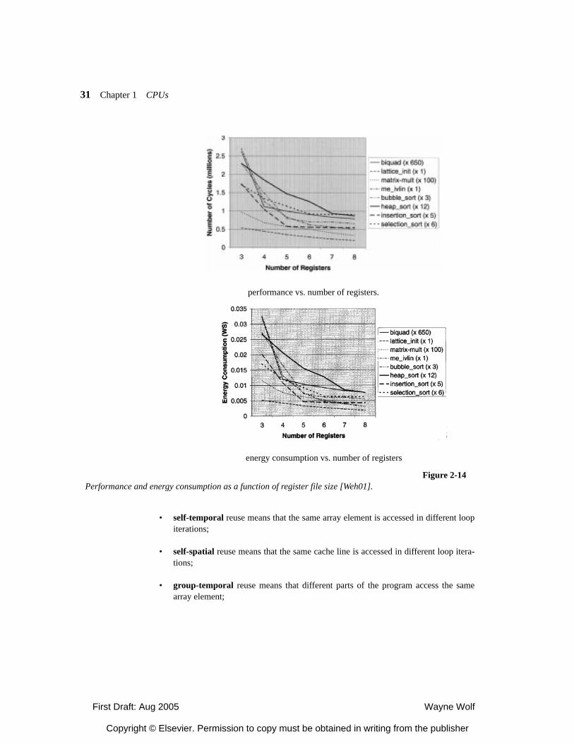
First Draft: Aug 2005 Wayne Wolf
Copyright © Elsevier. Permission to copy must be obtained in writing from the publisher
31 Chapter 1 CPUs
• self-temporal reuse means that the same array element is accessed in different loopiterations;
• self-spatial reuse means that the same cache line is accessed in different loop itera-tions;
• group-temporal reuse means that different parts of the program access the samearray element;
energy consumption vs. number of registers
performance vs. number of registers.
Figure 2-14Performance and energy consumption as a function of register file size [Weh01].
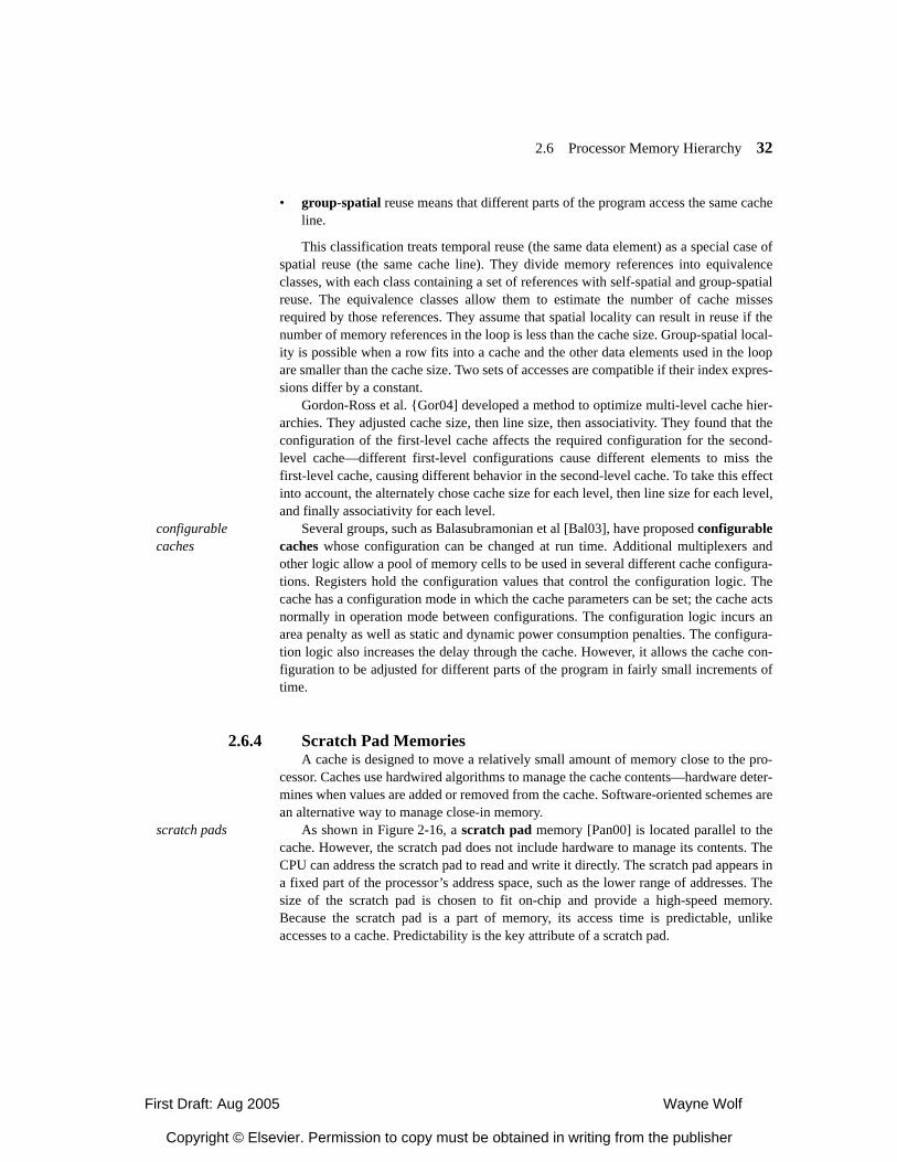
First Draft: Aug 2005 Wayne Wolf
Copyright © Elsevier. Permission to copy must be obtained in writing from the publisher
2.6 Processor Memory Hierarchy 32
• group-spatial reuse means that different parts of the program access the same cacheline.
This classification treats temporal reuse (the same data element) as a special case ofspatial reuse (the same cache line). They divide memory references into equivalenceclasses, with each class containing a set of references with self-spatial and group-spatialreuse. The equivalence classes allow them to estimate the number of cache missesrequired by those references. They assume that spatial locality can result in reuse if thenumber of memory references in the loop is less than the cache size. Group-spatial local-ity is possible when a row fits into a cache and the other data elements used in the loopare smaller than the cache size. Two sets of accesses are compatible if their index expres-sions differ by a constant.
Gordon-Ross et al. {Gor04] developed a method to optimize multi-level cache hier-archies. They adjusted cache size, then line size, then associativity. They found that theconfiguration of the first-level cache affects the required configuration for the second-level cache—different first-level configurations cause different elements to miss thefirst-level cache, causing different behavior in the second-level cache. To take this effectinto account, the alternately chose cache size for each level, then line size for each level,and finally associativity for each level.
configurable caches
Several groups, such as Balasubramonian et al [Bal03], have proposed configurablecaches whose configuration can be changed at run time. Additional multiplexers andother logic allow a pool of memory cells to be used in several different cache configura-tions. Registers hold the configuration values that control the configuration logic. Thecache has a configuration mode in which the cache parameters can be set; the cache actsnormally in operation mode between configurations. The configuration logic incurs anarea penalty as well as static and dynamic power consumption penalties. The configura-tion logic also increases the delay through the cache. However, it allows the cache con-figuration to be adjusted for different parts of the program in fairly small increments oftime.
2.6.4 Scratch Pad MemoriesA cache is designed to move a relatively small amount of memory close to the pro-
cessor. Caches use hardwired algorithms to manage the cache contents—hardware deter-mines when values are added or removed from the cache. Software-oriented schemes arean alternative way to manage close-in memory.
scratch pads As shown in Figure 2-16, a scratch pad memory [Pan00] is located parallel to thecache. However, the scratch pad does not include hardware to manage its contents. TheCPU can address the scratch pad to read and write it directly. The scratch pad appears ina fixed part of the processor’s address space, such as the lower range of addresses. Thesize of the scratch pad is chosen to fit on-chip and provide a high-speed memory.Because the scratch pad is a part of memory, its access time is predictable, unlikeaccesses to a cache. Predictability is the key attribute of a scratch pad.
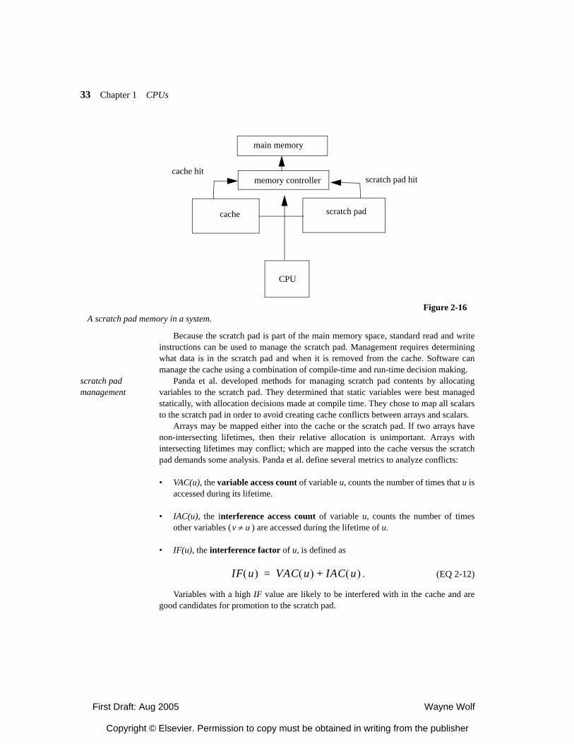
First Draft: Aug 2005 Wayne Wolf
Copyright © Elsevier. Permission to copy must be obtained in writing from the publisher
33 Chapter 1 CPUs
Because the scratch pad is part of the main memory space, standard read and writeinstructions can be used to manage the scratch pad. Management requires determiningwhat data is in the scratch pad and when it is removed from the cache. Software canmanage the cache using a combination of compile-time and run-time decision making.
scratch pad management
Panda et al. developed methods for managing scratch pad contents by allocatingvariables to the scratch pad. They determined that static variables were best managedstatically, with allocation decisions made at compile time. They chose to map all scalarsto the scratch pad in order to avoid creating cache conflicts between arrays and scalars.
Arrays may be mapped either into the cache or the scratch pad. If two arrays havenon-intersecting lifetimes, then their relative allocation is unimportant. Arrays withintersecting lifetimes may conflict; which are mapped into the cache versus the scratchpad demands some analysis. Panda et al. define several metrics to analyze conflicts:
• VAC(u), the variable access count of variable u, counts the number of times that u isaccessed during its lifetime.
• IAC(u), the interference access count of variable u, counts the number of timesother variables ( ) are accessed during the lifetime of u.
• IF(u), the interference factor of u, is defined as
. (EQ 2-12)
Variables with a high IF value are likely to be interfered with in the cache and aregood candidates for promotion to the scratch pad.
cache scratch pad
CPU
Figure 2-16A scratch pad memory in a system.
main memory
memory controller scratch pad hitcache hit
v u≠
IF u( ) VAC u( ) IAC u( )+=
First Draft: Aug 2005 Wayne Wolf
Copyright © Elsevier. Permission to copy must be obtained in writing from the publisher
2.6 Processor Memory Hierarchy 34
They then use these metrics to define a loop-oriented conflict metric, known as theloop conflict factor or LCF:
. (EQ 2-13)
In this formula, the outer summation is over all p loops in which u is accessed andthe inner summation is over all variables accessed in the ith loop.
The total conflict factor TCF for an array u is
. (EQ 2-14)
• data partitioning formulation
scratch pad allocation algorithms
These metrics are used by algorithms to allocate variables between the scratch padand main memory/cache. We can formulate the problem as follows:
• Given a set of arrays, each with a TCF value and a size
• and an SRAM of size S,
• find an optimal subset of arrays Q such that and is maxi-mized.
This problem is a generalized knapsack problem in that several arrays with non-overlapping lifetimes can intersect in the scratch pad. Panda et al.’s algorithm starts byclustering together arrays that could share scratch pad space. It then uses an approxima-tion algorithm that first sorts the items by value per weight as given by access densityAD:
. (EQ 2-15)
Arrays are then greedily selected for allocation to the scratch pad, starting with thearray with the highest AD value, until the scratch pad is full.
Figure 2-17 shows the allocation algorithm of Panda et al. Scalar variables are allo-cated to the scratch pad and arrays that are too large to fit into the scratch pad are allo-cated to main memory. A compatibility graph is created to determine arrays withcompatible lifetimes. Cliques are then allocated, but the algorithm may allocate either afull clique or a proper subset of the clique to the scratch pad. Clique analysis takes
LCF u( ) k u( ) k v( )v∑⎝ ⎠⎜ ⎟⎛ ⎞
+1 i p≤ ≤∑=
v u≠
TCF u( ) LCF u( ) IF u( )+=
A1 TCF A1( ) S1, ,{ } … An TCF An( ) Sn, ,{ }, ,
S Sii Q∈∑≥ TCF i( )
i Q∈∑
AD c( )
TCF v( )v c∈∑
max size v( ) v c∈,{ }---------------------------------------------------=
First Draft: Aug 2005 Wayne Wolf
Copyright © Elsevier. Permission to copy must be obtained in writing from the publisher
35 Chapter 1 CPUs
time and the algorithm can iterate n times, so the overall complexity of the algo-rithm is .
multitasking and scratch pads
When several programs execute on the CPU, all the programs compete for thescratch pad, much as they compete for the cache. However, because the scratch pad ismanaged in software, the allocation algorithm must take multitasking into account.Panda et al. propose dividing the scratch pad into segments and assigning each task itsown segment. This approach reduces run-time overhead for scratch pad management but
[Pan00] fig. 5
Figure 2-17An algorithm for scratch pad allocation [Pan00].
O n3( )O n4( )
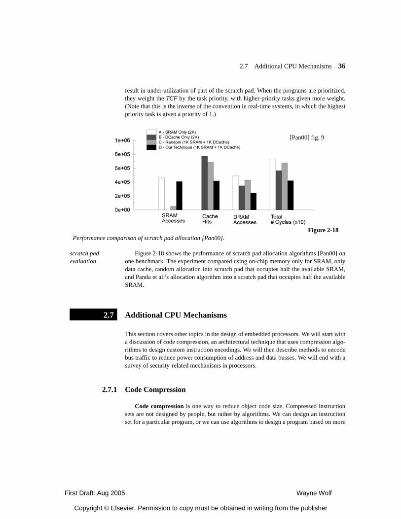
First Draft: Aug 2005 Wayne Wolf
Copyright © Elsevier. Permission to copy must be obtained in writing from the publisher
2.7 Additional CPU Mechanisms 36
result in under-utilization of part of the scratch pad. When the programs are prioritized,they weight the TCF by the task priority, with higher-priority tasks given more weight.(Note that this is the inverse of the convention in real-time systems, in which the highestpriority task is given a priority of 1.)
scratch pad evaluation
Figure 2-18 shows the performance of scratch pad allocation algorithms [Pan00] onone benchmark. The experiment compared using on-chip memory only for SRAM, onlydata cache, random allocation into scratch pad that occupies half the available SRAM,and Panda et al.’s allocation algorithm into a scratch pad that occupies half the availableSRAM.
Additional CPU Mechanisms
This section covers other topics in the design of embedded processors. We will start witha discussion of code compression, an architectural technique that uses compression algo-rithms to design custom instruction encodings. We will then describe methods to encodebus traffic to reduce power consumption of address and data busses. We will end with asurvey of security-related mechanisms in processors.
2.7.1 Code Compression
Code compression is one way to reduce object code size. Compressed instructionsets are not designed by people, but rather by algorithms. We can design an instructionset for a particular program, or we can use algorithms to design a program based on more
[Pan00] fig. 9
Figure 2-18Performance comparison of scratch pad allocation [Pan00].
2.7
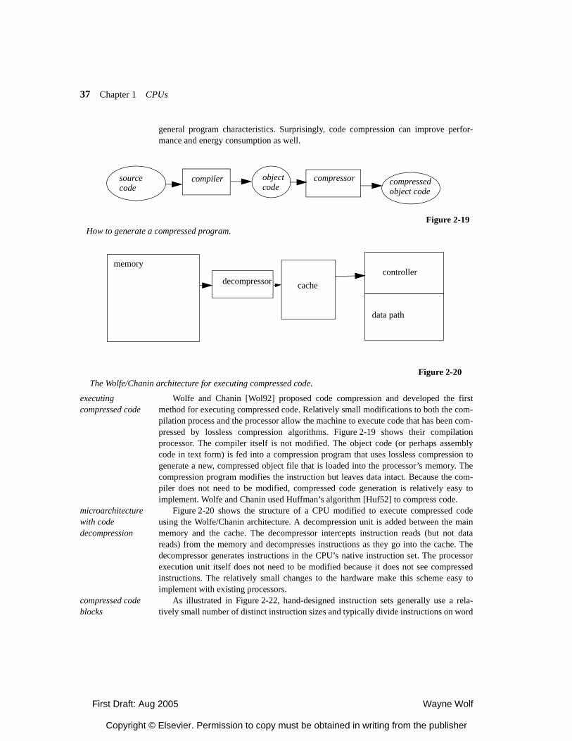
First Draft: Aug 2005 Wayne Wolf
Copyright © Elsevier. Permission to copy must be obtained in writing from the publisher
37 Chapter 1 CPUs
general program characteristics. Surprisingly, code compression can improve perfor-mance and energy consumption as well.
executing compressed code
Wolfe and Chanin [Wol92] proposed code compression and developed the firstmethod for executing compressed code. Relatively small modifications to both the com-pilation process and the processor allow the machine to execute code that has been com-pressed by lossless compression algorithms. Figure 2-19 shows their compilationprocessor. The compiler itself is not modified. The object code (or perhaps assemblycode in text form) is fed into a compression program that uses lossless compression togenerate a new, compressed object file that is loaded into the processor’s memory. Thecompression program modifies the instruction but leaves data intact. Because the com-piler does not need to be modified, compressed code generation is relatively easy toimplement. Wolfe and Chanin used Huffman’s algorithm [Huf52] to compress code.
microarchitecture with code decompression
Figure 2-20 shows the structure of a CPU modified to execute compressed codeusing the Wolfe/Chanin architecture. A decompression unit is added between the mainmemory and the cache. The decompressor intercepts instruction reads (but not datareads) from the memory and decompresses instructions as they go into the cache. Thedecompressor generates instructions in the CPU’s native instruction set. The processorexecution unit itself does not need to be modified because it does not see compressedinstructions. The relatively small changes to the hardware make this scheme easy toimplement with existing processors.
compressed code blocks
As illustrated in Figure 2-22, hand-designed instruction sets generally use a rela-tively small number of distinct instruction sizes and typically divide instructions on word
Figure 2-19How to generate a compressed program.
sourcecode
compiler objectcode
compressor compressedobject code
Figure 2-20The Wolfe/Chanin architecture for executing compressed code.
controller
data path
memory
decompressor cache
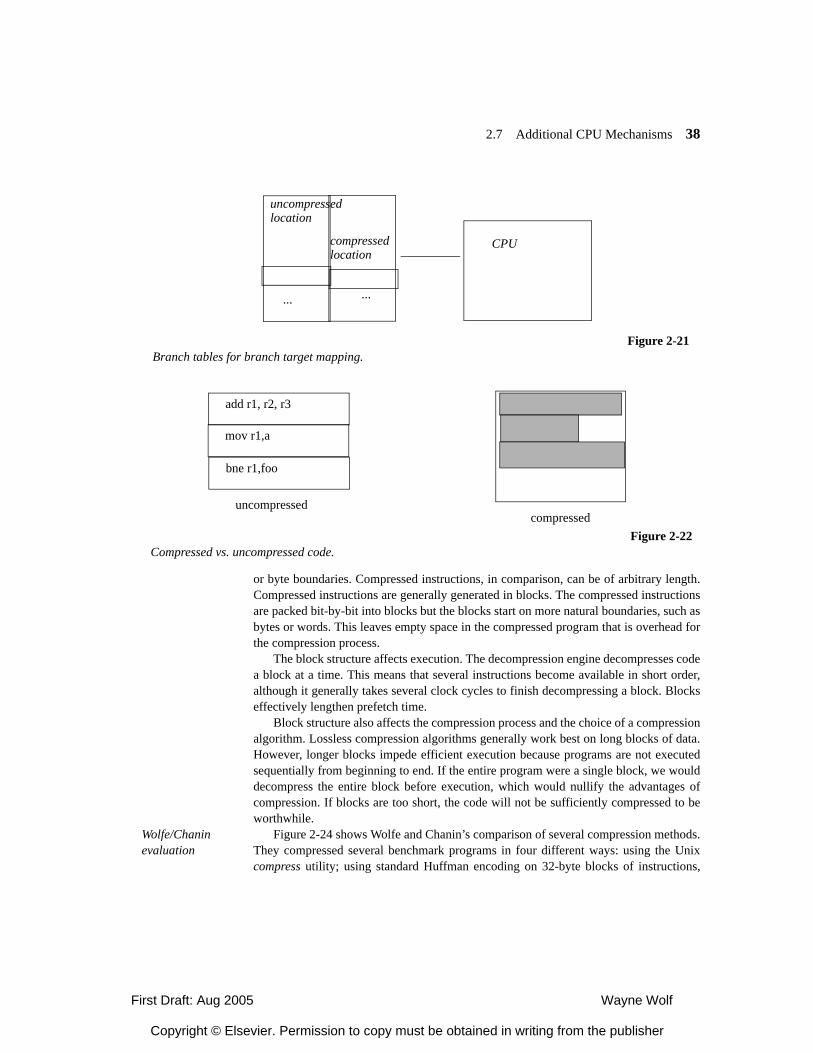
First Draft: Aug 2005 Wayne Wolf
Copyright © Elsevier. Permission to copy must be obtained in writing from the publisher
2.7 Additional CPU Mechanisms 38
or byte boundaries. Compressed instructions, in comparison, can be of arbitrary length.Compressed instructions are generally generated in blocks. The compressed instructionsare packed bit-by-bit into blocks but the blocks start on more natural boundaries, such asbytes or words. This leaves empty space in the compressed program that is overhead forthe compression process.
The block structure affects execution. The decompression engine decompresses codea block at a time. This means that several instructions become available in short order,although it generally takes several clock cycles to finish decompressing a block. Blockseffectively lengthen prefetch time.
Block structure also affects the compression process and the choice of a compressionalgorithm. Lossless compression algorithms generally work best on long blocks of data.However, longer blocks impede efficient execution because programs are not executedsequentially from beginning to end. If the entire program were a single block, we woulddecompress the entire block before execution, which would nullify the advantages ofcompression. If blocks are too short, the code will not be sufficiently compressed to beworthwhile.
Wolfe/Chanin evaluation
Figure 2-24 shows Wolfe and Chanin’s comparison of several compression methods.They compressed several benchmark programs in four different ways: using the Unixcompress utility; using standard Huffman encoding on 32-byte blocks of instructions,
Figure 2-21Branch tables for branch target mapping.
CPU
uncompressedlocation
compressedlocation
... ...
add r1, r2, r3
mov r1,a
bne r1,foo
uncompressedcompressed
Figure 2-22Compressed vs. uncompressed code.
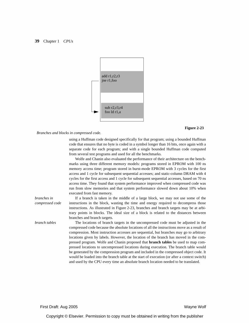
First Draft: Aug 2005 Wayne Wolf
Copyright © Elsevier. Permission to copy must be obtained in writing from the publisher
39 Chapter 1 CPUs
using a Huffman code designed specifically for that program; using a bounded Huffmancode that ensures that no byte is coded in a symbol longer than 16 bits, once again with aseparate code for each program; and with a single bounded Huffman code computedfrom several test programs and used for all the benchmarks.
Wolfe and Chanin also evaluated the performance of their architecture on the bench-marks using three different memory models: programs stored in EPROM with 100 nsmemory access time; program stored in burst-mode EPROM with 3 cycles for the firstaccess and 1 cycle for subsequent sequential accesses; and static-column DRAM with 4cycles for the first access and 1 cycle for subsequent sequential accesses, based on 70 nsaccess time. They found that system performance improved when compressed code wasrun from slow memories and that system performance slowed down about 10% whenexecuted from fast memory.
branches in compressed code
If a branch is taken in the middle of a large block, we may not use some of theinstructions in the block, wasting the time and energy required to decompress thoseinstructions. As illustrated in Figure 2-23, branches and branch targets may be at arbi-trary points in blocks. The ideal size of a block is related to the distances betweenbranches and branch targets.
branch tables The locations of branch targets in the uncompressed code must be adjusted in thecompressed code because the absolute locations of all the instructions move as a result ofcompression. Most instruction accesses are sequential, but branches may go to arbitrarylocations given by labels. However, the location of the branch has moved in the com-pressed program. Wolfe and Chanin proposed that branch tables be used to map com-pressed locations to uncompressed locations during execution. The branch table wouldbe generated by the compression program and included in the compressed object code. Itwould be loaded into the branch table at the start of execution (or after a context switch)and used by the CPU every time an absolute branch location needed to be translated.
add r1,r2,r3jne r1,foo
sub r2,r3,r4foo ld r1,a
Figure 2-23Branches and blocks in compressed code.
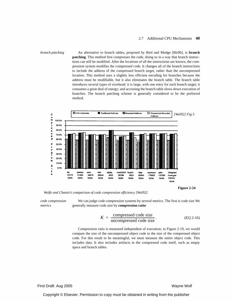
First Draft: Aug 2005 Wayne Wolf
Copyright © Elsevier. Permission to copy must be obtained in writing from the publisher
2.7 Additional CPU Mechanisms 40
branch patching An alternative to branch tables, proposed by Bird and Mudge [Bir96], is branchpatching. This method first compresses the code, doing so in a way that branch instruc-tions can still be modified. After the locations of all the instructions are known, the com-pression system modifies the compressed code. It changes all of the branch instructionsto include the address of the compressed branch target, rather than the uncompressedlocation. This method uses a slightly less efficient encoding for branches because theaddress must be modifiable, but it also eliminates the branch table. The branch tableintroduces several types of overhead: it is large, with one entry for each branch target; itconsumes a great deal of energy; and accessing the branch table slows down execution ofbranches. The branch patching scheme is generally considered to be the preferredmethod.
code compression metrics
We can judge code compression systems by several metrics. The first is code size Wegenerally measure code size by compression ratio:
. (EQ 2-16)
Compression ratio is measured independent of execution; in Figure 2-19, we wouldcompare the size of the uncompressed object code to the size of the compressed objectcode. For this result to be meaningful, we must measure the entire object code. Thisincludes data. It also includes artifacts in the compressed code itself, such as emptyspace and branch tables.
Figure 2-24Wolfe and Chanin’s comparison of code compression efficiency [Wol92]
[Wol92] Fig 5
K compressed code sizeuncompressed code size----------------------------------------------------------=
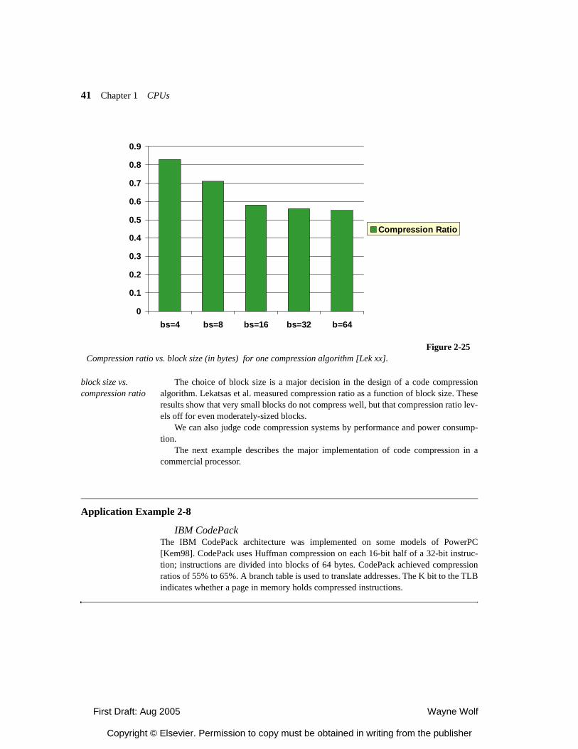
First Draft: Aug 2005 Wayne Wolf
Copyright © Elsevier. Permission to copy must be obtained in writing from the publisher
41 Chapter 1 CPUs
block size vs. compression ratio
The choice of block size is a major decision in the design of a code compressionalgorithm. Lekatsas et al. measured compression ratio as a function of block size. Theseresults show that very small blocks do not compress well, but that compression ratio lev-els off for even moderately-sized blocks.
We can also judge code compression systems by performance and power consump-tion.
The next example describes the major implementation of code compression in acommercial processor.
Application Example 2-8
IBM CodePackThe IBM CodePack architecture was implemented on some models of PowerPC[Kem98]. CodePack uses Huffman compression on each 16-bit half of a 32-bit instruc-tion; instructions are divided into blocks of 64 bytes. CodePack achieved compressionratios of 55% to 65%. A branch table is used to translate addresses. The K bit to the TLBindicates whether a page in memory holds compressed instructions.
0
0.1
0.2
0.3
0.4
0.5
0.6
0.7
0.8
0.9
bs=4 bs=8 bs=16 bs=32 b=64
Compression Ratio
Figure 2-25Compression ratio vs. block size (in bytes) for one compression algorithm [Lek xx].
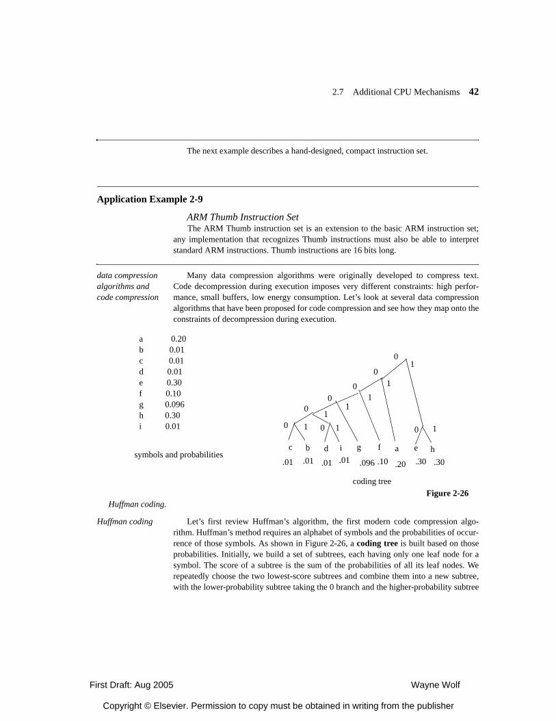
First Draft: Aug 2005 Wayne Wolf
Copyright © Elsevier. Permission to copy must be obtained in writing from the publisher
2.7 Additional CPU Mechanisms 42
The next example describes a hand-designed, compact instruction set.
Application Example 2-9
ARM Thumb Instruction SetThe ARM Thumb instruction set is an extension to the basic ARM instruction set;
any implementation that recognizes Thumb instructions must also be able to interpretstandard ARM instructions. Thumb instructions are 16 bits long.
data compression algorithms and code compression
Many data compression algorithms were originally developed to compress text.Code decompression during execution imposes very different constraints: high perfor-mance, small buffers, low energy consumption. Let’s look at several data compressionalgorithms that have been proposed for code compression and see how they map onto theconstraints of decompression during execution.
Huffman coding Let’s first review Huffman’s algorithm, the first modern code compression algo-rithm. Huffman’s method requires an alphabet of symbols and the probabilities of occur-rence of those symbols. As shown in Figure 2-26, a coding tree is built based on thoseprobabilities. Initially, we build a set of subtrees, each having only one leaf node for asymbol. The score of a subtree is the sum of the probabilities of all its leaf nodes. Werepeatedly choose the two lowest-score subtrees and combine them into a new subtree,with the lower-probability subtree taking the 0 branch and the higher-probability subtree
Figure 2-26Huffman coding.
a 0.20b 0.01c 0.01d 0.01e 0.30f 0.10g 0.096h 0.30i 0.01
symbols and probabilities
coding tree
c b d i f a e hg
.01 .01 .01 .01 .096 .10 .20 .30 .30
0 1 0
00
0
0
1
11
1
1
1
10
0
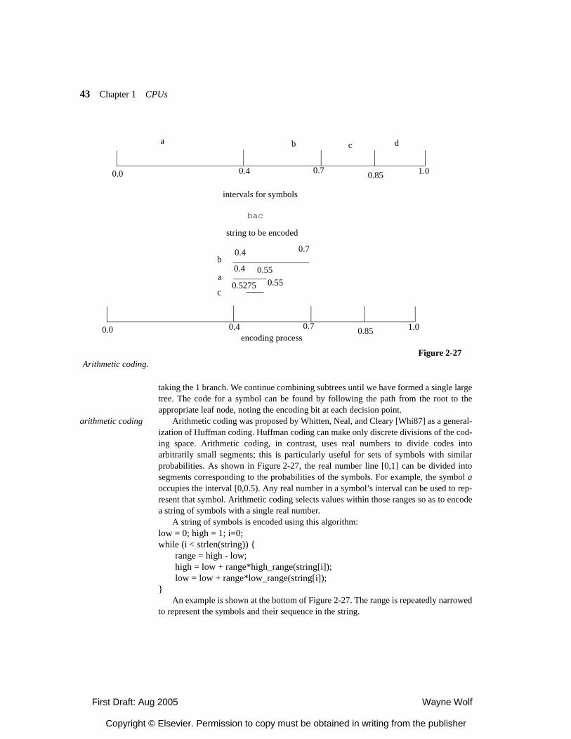
First Draft: Aug 2005 Wayne Wolf
Copyright © Elsevier. Permission to copy must be obtained in writing from the publisher
43 Chapter 1 CPUs
taking the 1 branch. We continue combining subtrees until we have formed a single largetree. The code for a symbol can be found by following the path from the root to theappropriate leaf node, noting the encoding bit at each decision point.
arithmetic coding Arithmetic coding was proposed by Whitten, Neal, and Cleary [Whi87] as a general-ization of Huffman coding. Huffman coding can make only discrete divisions of the cod-ing space. Arithmetic coding, in contrast, uses real numbers to divide codes intoarbitrarily small segments; this is particularly useful for sets of symbols with similarprobabilities. As shown in Figure 2-27, the real number line [0,1] can be divided intosegments corresponding to the probabilities of the symbols. For example, the symbol aoccupies the interval [0,0.5). Any real number in a symbol’s interval can be used to rep-resent that symbol. Arithmetic coding selects values within those ranges so as to encodea string of symbols with a single real number.
A string of symbols is encoded using this algorithm:low = 0; high = 1; i=0;while (i < strlen(string)) {
range = high - low;high = low + range*high_range(string[i]);low = low + range*low_range(string[i]);
}An example is shown at the bottom of Figure 2-27. The range is repeatedly narrowed
to represent the symbols and their sequence in the string.
Figure 2-27Arithmetic coding.
a b c d
0.0 0.4 0.7 0.85 1.0
intervals for symbols
bac
string to be encoded
0.0 0.4 0.7 0.85 1.0
b0.4 0.7
a
c
0.4 0.55
0.5275 0.55
encoding process
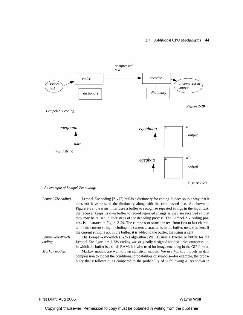
First Draft: Aug 2005 Wayne Wolf
Copyright © Elsevier. Permission to copy must be obtained in writing from the publisher
2.7 Additional CPU Mechanisms 44
Lempel-Ziv coding Lempel-Ziv coding [Ziv77] builds a dictionary for coding. It does so in a way that itdoes not have to send the dictionary along with the compressed text. As shown inFigure 2-28, the transmitter uses a buffer to recognize repeated strings in the input text;the receiver keeps its own buffer to record repeated strings as they are received so thatthey may be reused in later steps of the decoding process. The Lempel-Ziv coding pro-cess is illustrated in Figure 2-29. The compressor scans the text from first to last charac-ter. If the current string, including the current character, is in the buffer, no text is sent. Ifthe current string is not in the buffer, it is added to the buffer, the string is sent.
Lempel-Ziv-Welch coding
The Lempel-Ziv-Welch (LZW) algorithm [Wel84] uses a fixed-size buffer for theLempel-Ziv algorithm. LZW coding was originally designed for disk drive compression,in which the buffer is a small RAM; it is also used for image encoding in the GIF format.
Markov models Markov models are well-known statistical models. We use Markov models in datacompression to model the conditional probabilities of symbols—for example, the proba-bility that z follows a, as compared to the probability of w following a. As shown in
Figure 2-28Lempel-Ziv coding.
dictionary
sourcetext
compressedtext
uncompressedsource
coder
dictionary
decoder
Figure 2-29An example of Lempel-Ziv coding.
egegbaaa
start
input string
aegegbaaa a
output
aegegbaa aT
output
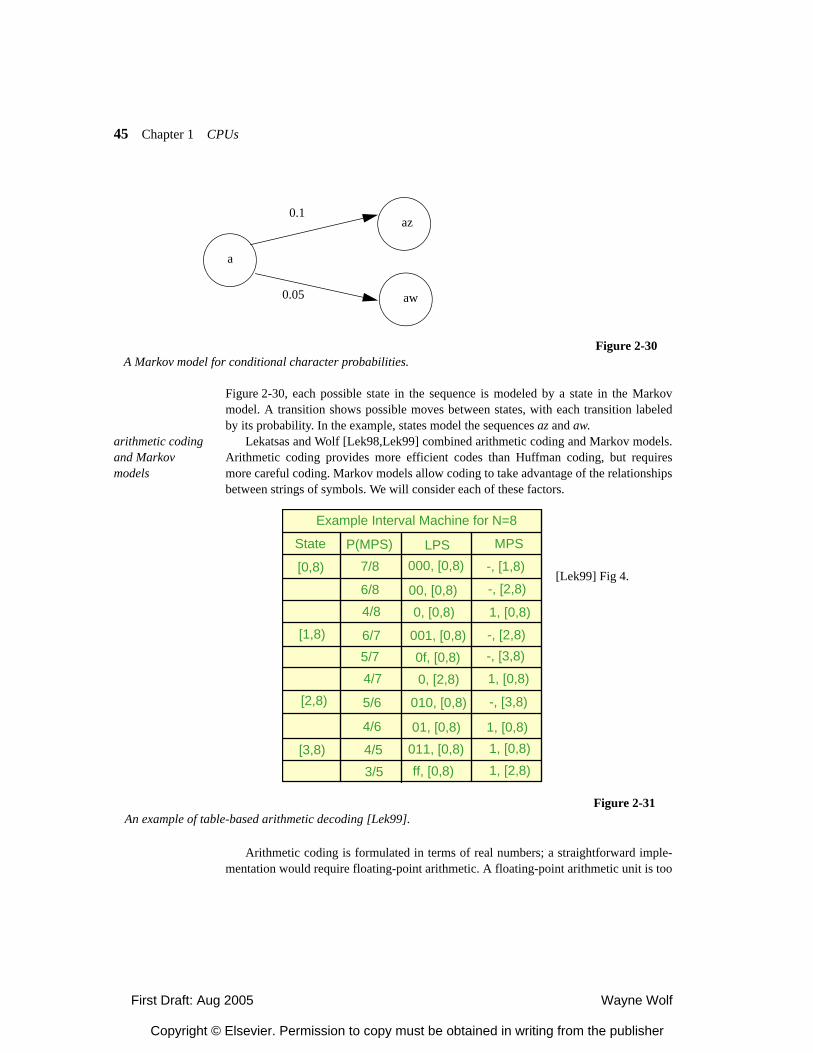
First Draft: Aug 2005 Wayne Wolf
Copyright © Elsevier. Permission to copy must be obtained in writing from the publisher
45 Chapter 1 CPUs
Figure 2-30, each possible state in the sequence is modeled by a state in the Markovmodel. A transition shows possible moves between states, with each transition labeledby its probability. In the example, states model the sequences az and aw.
arithmetic coding and Markov models
Lekatsas and Wolf [Lek98,Lek99] combined arithmetic coding and Markov models.Arithmetic coding provides more efficient codes than Huffman coding, but requiresmore careful coding. Markov models allow coding to take advantage of the relationshipsbetween strings of symbols. We will consider each of these factors.
Arithmetic coding is formulated in terms of real numbers; a straightforward imple-mentation would require floating-point arithmetic. A floating-point arithmetic unit is too
a
az
aw
0.1
0.05
Figure 2-30A Markov model for conditional character probabilities.
Figure 2-31An example of table-based arithmetic decoding [Lek99].
Example Interval Machine for N=8
State
[0,8)
P(MPS) LPS MPS
7/8
3/54/5
4/6
5/6
4/75/76/7
4/86/8
[1,8)
[3,8)
[2,8)
000, [0,8)
00, [0,8)0, [0,8)
001, [0,8)0f, [0,8)0, [2,8)
010, [0,8)
011, [0,8)01, [0,8)
ff, [0,8) 1, [2,8)1, [0,8)1, [0,8)
-, [3,8)
1, [0,8)
-, [3,8)-, [2,8)
1, [0,8)
-, [2,8)
-, [1,8)[Lek99] Fig 4.
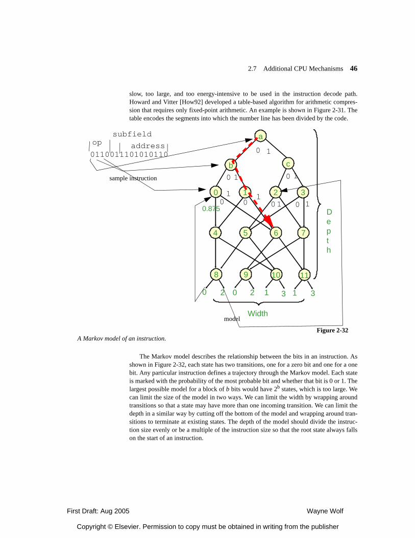
First Draft: Aug 2005 Wayne Wolf
Copyright © Elsevier. Permission to copy must be obtained in writing from the publisher
2.7 Additional CPU Mechanisms 46
slow, too large, and too energy-intensive to be used in the instruction decode path.Howard and Vitter [How92] developed a table-based algorithm for arithmetic compres-sion that requires only fixed-point arithmetic. An example is shown in Figure 2-31. Thetable encodes the segments into which the number line has been divided by the code.
The Markov model describes the relationship between the bits in an instruction. Asshown in Figure 2-32, each state has two transitions, one for a zero bit and one for a onebit. Any particular instruction defines a trajectory through the Markov model. Each stateis marked with the probability of the most probable bit and whether that bit is 0 or 1. Thelargest possible model for a block of b bits would have 2b states, which is too large. Wecan limit the size of the model in two ways. We can limit the width by wrapping aroundtransitions so that a state may have more than one incoming transition. We can limit thedepth in a similar way by cutting off the bottom of the model and wrapping around tran-sitions to terminate at existing states. The depth of the model should divide the instruc-tion size evenly or be a multiple of the instruction size so that the root state always fallson the start of an instruction.
0110011101010110
opsubfield
address
1 2 3
4 5 6 7
8 9
0
10 11
Depth
Width
0.875
0 2 0 2 1 1 3
b c
a
3
0 1
0 1 0 1
01
01
0 01 1
Figure 2-32A Markov model of an instruction.
sample instruction
model
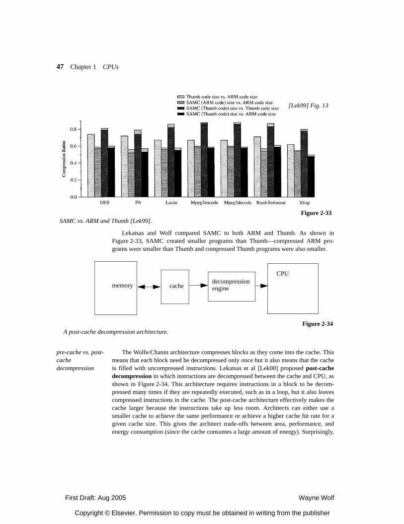
First Draft: Aug 2005 Wayne Wolf
Copyright © Elsevier. Permission to copy must be obtained in writing from the publisher
47 Chapter 1 CPUs
Lekatsas and Wolf compared SAMC to both ARM and Thumb. As shown inFigure 2-33, SAMC created smaller programs than Thumb—compressed ARM pro-grams were smaller than Thumb and compressed Thumb programs were also smaller.
pre-cache vs. post-cache decompression
The Wolfe/Chanin architecture compresses blocks as they come into the cache. Thismeans that each block need be decompressed only once but it also means that the cacheis filled with uncompressed instructions. Lekatsas et al [Lek00] proposed post-cachedecompression in which instructions are decompressed between the cache and CPU, asshown in Figure 2-34. This architecture requires instructions in a block to be decom-pressed many times if they are repeatedly executed, such as in a loop, but it also leavescompressed instructions in the cache. The post-cache architecture effectively makes thecache larger because the instructions take up less room. Architects can either use asmaller cache to achieve the same performance or achieve a higher cache hit rate for agiven cache size. This gives the architect trade-offs between area, performance, andenergy consumption (since the cache consumes a large amount of energy). Surprisingly,
Figure 2-33SAMC vs. ARM and Thumb [Lek99].
[Lek99] Fig. 13
CPU
cachedecompressionenginememory
Figure 2-34A post-cache decompression architecture.
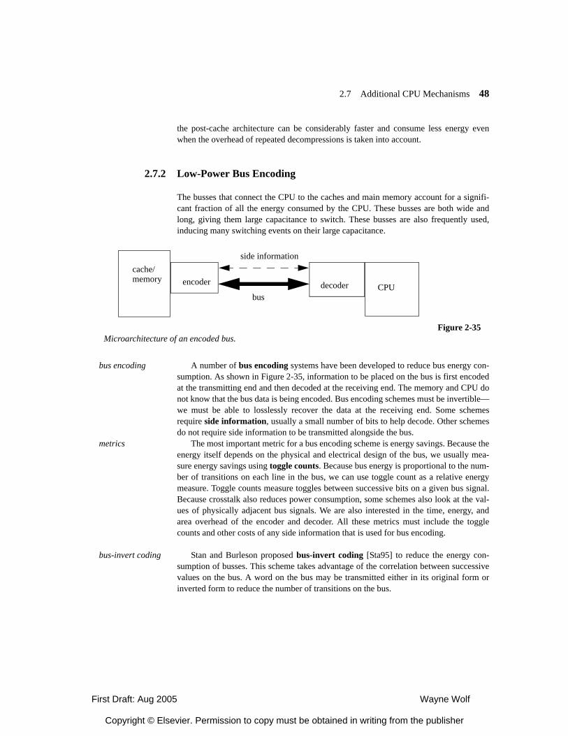
First Draft: Aug 2005 Wayne Wolf
Copyright © Elsevier. Permission to copy must be obtained in writing from the publisher
2.7 Additional CPU Mechanisms 48
the post-cache architecture can be considerably faster and consume less energy evenwhen the overhead of repeated decompressions is taken into account.
2.7.2 Low-Power Bus Encoding
The busses that connect the CPU to the caches and main memory account for a signifi-cant fraction of all the energy consumed by the CPU. These busses are both wide andlong, giving them large capacitance to switch. These busses are also frequently used,inducing many switching events on their large capacitance.
bus encoding A number of bus encoding systems have been developed to reduce bus energy con-sumption. As shown in Figure 2-35, information to be placed on the bus is first encodedat the transmitting end and then decoded at the receiving end. The memory and CPU donot know that the bus data is being encoded. Bus encoding schemes must be invertible—we must be able to losslessly recover the data at the receiving end. Some schemesrequire side information, usually a small number of bits to help decode. Other schemesdo not require side information to be transmitted alongside the bus.
metrics The most important metric for a bus encoding scheme is energy savings. Because theenergy itself depends on the physical and electrical design of the bus, we usually mea-sure energy savings using toggle counts. Because bus energy is proportional to the num-ber of transitions on each line in the bus, we can use toggle count as a relative energymeasure. Toggle counts measure toggles between successive bits on a given bus signal.Because crosstalk also reduces power consumption, some schemes also look at the val-ues of physically adjacent bus signals. We are also interested in the time, energy, andarea overhead of the encoder and decoder. All these metrics must include the togglecounts and other costs of any side information that is used for bus encoding.
bus-invert coding Stan and Burleson proposed bus-invert coding [Sta95] to reduce the energy con-sumption of busses. This scheme takes advantage of the correlation between successivevalues on the bus. A word on the bus may be transmitted either in its original form orinverted form to reduce the number of transitions on the bus.
CPUdecoder
cache/memory encoder
side information
bus
Figure 2-35Microarchitecture of an encoded bus.
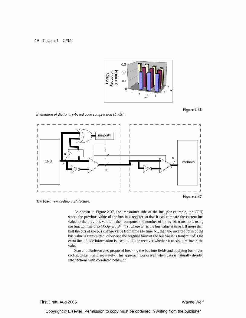
First Draft: Aug 2005 Wayne Wolf
Copyright © Elsevier. Permission to copy must be obtained in writing from the publisher
49 Chapter 1 CPUs
As shown in Figure 2-37, the transmitter side of the bus (for example, the CPU)stores the previous value of the bus in a register so that it can compare the current busvalue to the previous value. It then computes the number of bit-by-bit transitions usingthe function , where is the bus value at time t. If more thanhalf the bits of the bus change value from time t to time t-1, then the inverted form of thebus value is transmitted, otherwise the original form of the bus value is transmitted. Oneextra line of side information is used to tell the receiver whether it needs to re-invert thevalue.
Stan and Burleson also proposed breaking the bus into fields and applying bus-invertcoding to each field separately. This approach works well when data is naturally dividedinto sections with correlated behavior.
3 4 5 6
4
60
0.1
0.2
0.3
Ener
gyR
educ
tion
(1 =
100%
)
wo
wi
Figure 2-36Evaluation of dictionary-based code compression [Lv03].
memoryCPU
majority
n1
n
n
Figure 2-37The bus-invert coding architecture.
majority XOR Bt Bt 1–,( )( ) Bt
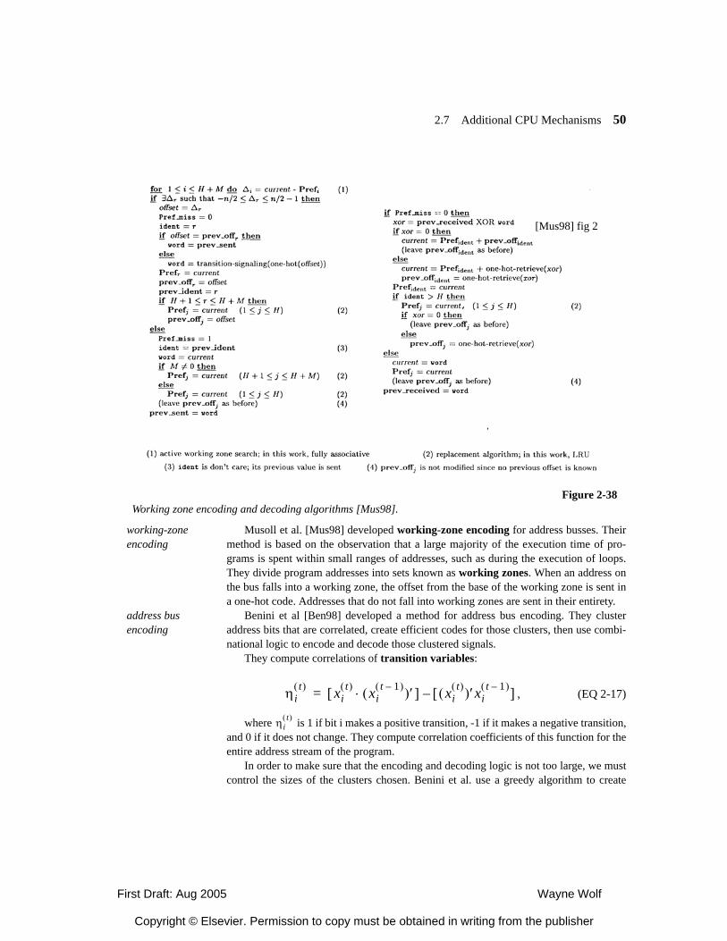
First Draft: Aug 2005 Wayne Wolf
Copyright © Elsevier. Permission to copy must be obtained in writing from the publisher
2.7 Additional CPU Mechanisms 50
working-zone encoding
Musoll et al. [Mus98] developed working-zone encoding for address busses. Theirmethod is based on the observation that a large majority of the execution time of pro-grams is spent within small ranges of addresses, such as during the execution of loops.They divide program addresses into sets known as working zones. When an address onthe bus falls into a working zone, the offset from the base of the working zone is sent ina one-hot code. Addresses that do not fall into working zones are sent in their entirety.
address bus encoding
Benini et al [Ben98] developed a method for address bus encoding. They clusteraddress bits that are correlated, create efficient codes for those clusters, then use combi-national logic to encode and decode those clustered signals.
They compute correlations of transition variables:
, (EQ 2-17)
where is 1 if bit i makes a positive transition, -1 if it makes a negative transition,and 0 if it does not change. They compute correlation coefficients of this function for theentire address stream of the program.
In order to make sure that the encoding and decoding logic is not too large, we mustcontrol the sizes of the clusters chosen. Benini et al. use a greedy algorithm to create
Figure 2-38Working zone encoding and decoding algorithms [Mus98].
[Mus98] fig 2
ηit( ) xi
t( ) xit 1–( )( )′⋅[ ] xi
t( )( )′xit 1–( )[ ]–=
ηit( )
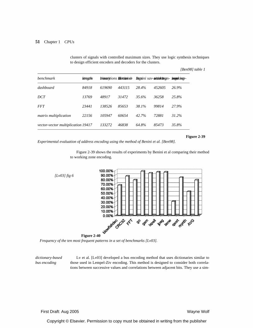
First Draft: Aug 2005 Wayne Wolf
Copyright © Elsevier. Permission to copy must be obtained in writing from the publisher
51 Chapter 1 CPUs
clusters of signals with controlled maximum sizes. They use logic synthesis techniquesto design efficient encoders and decoders for the clusters.
Figure 2-39 shows the results of experiments by Benini et al comparing their methodto working zone encoding.
dictionary-based bus encoding
Lv et al. [Lv03] developed a bus encoding method that uses dictionaries similar tothose used in Lempel-Ziv encoding. This method is designed to consider both correla-tions between successive values and correlations between adjacent bits. They use a sim-
benchmark stream length binary transitions Benini et al transi-tions Benini sav-ings working zone tran-sitions working zone sav-ings
dashboard 84918 619690 443115 28.4% 452605 26.9%
DCT 13769 48917 31472 35.6% 36258 25.8%
FFT 23441 138526 85653 38.1% 99814 27.9%
matrix multiplication 22156 105947 60654 42.7% 72881 31.2%
vector-vector multiplication 19417 133272 46838 64.8% 85473 35.8%
[Ben98] table 1
Figure 2-39Experimental evaluation of address encoding using the method of Benini et al. [Ben98].
Figure 2-40Frequency of the ten most frequent patterns in a set of benchmarks [Lv03].
[Lv03] fig 6
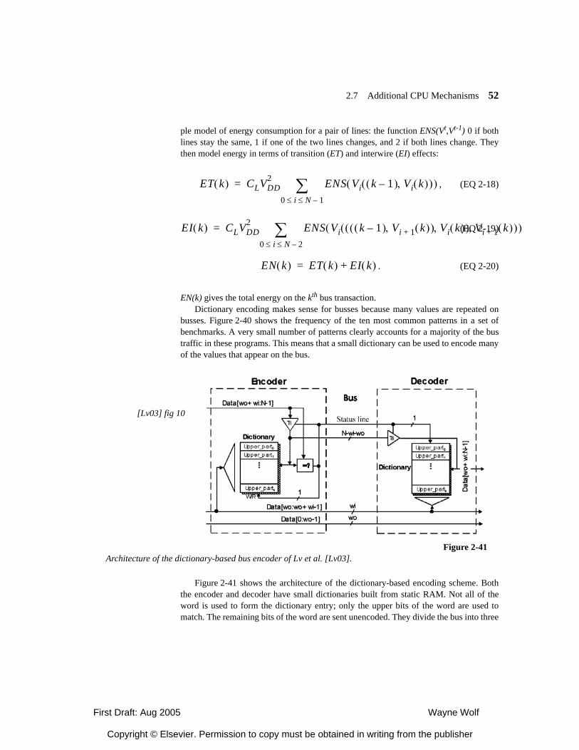
First Draft: Aug 2005 Wayne Wolf
Copyright © Elsevier. Permission to copy must be obtained in writing from the publisher
2.7 Additional CPU Mechanisms 52
ple model of energy consumption for a pair of lines: the function ENS(Vt,Vt-1) 0 if bothlines stay the same, 1 if one of the two lines changes, and 2 if both lines change. Theythen model energy in terms of transition (ET) and interwire (EI) effects:
, (EQ 2-18)
(EQ 2-19)
. (EQ 2-20)
EN(k) gives the total energy on the kth bus transaction.Dictionary encoding makes sense for busses because many values are repeated on
busses. Figure 2-40 shows the frequency of the ten most common patterns in a set ofbenchmarks. A very small number of patterns clearly accounts for a majority of the bustraffic in these programs. This means that a small dictionary can be used to encode manyof the values that appear on the bus.
Figure 2-41 shows the architecture of the dictionary-based encoding scheme. Boththe encoder and decoder have small dictionaries built from static RAM. Not all of theword is used to form the dictionary entry; only the upper bits of the word are used tomatch. The remaining bits of the word are sent unencoded. They divide the bus into three
ET k( ) CLVDD2 ENS Vi k 1–( ) Vi k( ),( )( )
0 i N 1–≤ ≤∑=
EI k( ) CLVDD2 ENS Vi k 1–( ) Vi 1+ k( ),( ) Vi k( ),( ) Vi 1+ k( ),( )( )
0 i N 2–≤ ≤∑=
EN k( ) ET k( ) EI k( )+=
Figure 2-41Architecture of the dictionary-based bus encoder of Lv et al. [Lv03].
[Lv03] fig 10
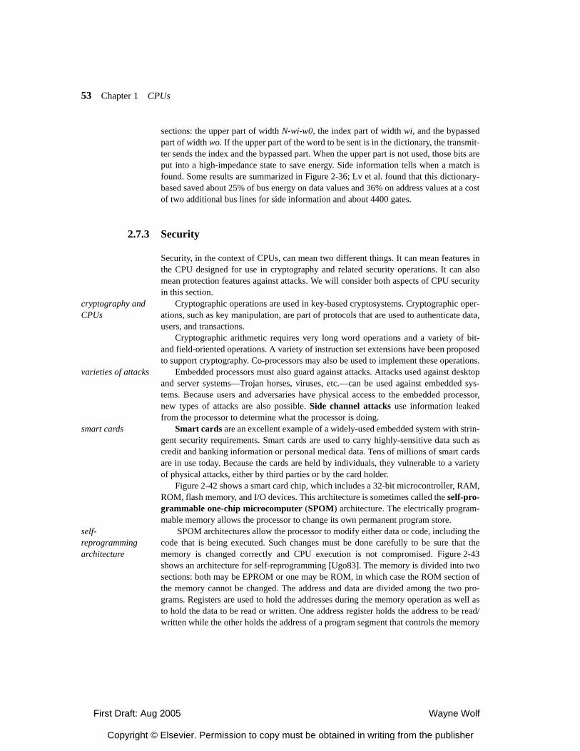
First Draft: Aug 2005 Wayne Wolf
Copyright © Elsevier. Permission to copy must be obtained in writing from the publisher
53 Chapter 1 CPUs
sections: the upper part of width N-wi-w0, the index part of width wi, and the bypassedpart of width wo. If the upper part of the word to be sent is in the dictionary, the transmit-ter sends the index and the bypassed part. When the upper part is not used, those bits areput into a high-impedance state to save energy. Side information tells when a match isfound. Some results are summarized in Figure 2-36; Lv et al. found that this dictionary-based saved about 25% of bus energy on data values and 36% on address values at a costof two additional bus lines for side information and about 4400 gates.
2.7.3 Security
Security, in the context of CPUs, can mean two different things. It can mean features inthe CPU designed for use in cryptography and related security operations. It can alsomean protection features against attacks. We will consider both aspects of CPU securityin this section.
cryptography and CPUs
Cryptographic operations are used in key-based cryptosystems. Cryptographic oper-ations, such as key manipulation, are part of protocols that are used to authenticate data,users, and transactions.
Cryptographic arithmetic requires very long word operations and a variety of bit-and field-oriented operations. A variety of instruction set extensions have been proposedto support cryptography. Co-processors may also be used to implement these operations.
varieties of attacks Embedded processors must also guard against attacks. Attacks used against desktopand server systems—Trojan horses, viruses, etc.—can be used against embedded sys-tems. Because users and adversaries have physical access to the embedded processor,new types of attacks are also possible. Side channel attacks use information leakedfrom the processor to determine what the processor is doing.
smart cards Smart cards are an excellent example of a widely-used embedded system with strin-gent security requirements. Smart cards are used to carry highly-sensitive data such ascredit and banking information or personal medical data. Tens of millions of smart cardsare in use today. Because the cards are held by individuals, they vulnerable to a varietyof physical attacks, either by third parties or by the card holder.
Figure 2-42 shows a smart card chip, which includes a 32-bit microcontroller, RAM,ROM, flash memory, and I/O devices. This architecture is sometimes called the self-pro-grammable one-chip microcomputer (SPOM) architecture. The electrically program-mable memory allows the processor to change its own permanent program store.
self-reprogramming architecture
SPOM architectures allow the processor to modify either data or code, including thecode that is being executed. Such changes must be done carefully to be sure that thememory is changed correctly and CPU execution is not compromised. Figure 2-43shows an architecture for self-reprogramming [Ugo83]. The memory is divided into twosections: both may be EPROM or one may be ROM, in which case the ROM section ofthe memory cannot be changed. The address and data are divided among the two pro-grams. Registers are used to hold the addresses during the memory operation as well asto hold the data to be read or written. One address register holds the address to be read/written while the other holds the address of a program segment that controls the memory
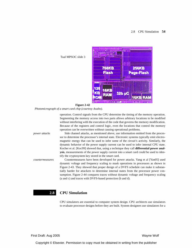
First Draft: Aug 2005 Wayne Wolf
Copyright © Elsevier. Permission to copy must be obtained in writing from the publisher
2.8 CPU Simulation 54
operation. Control signals from the CPU determine the timing of the memory operation.Segmenting the memory access into two parts allows arbitrary locations to be modifiedwithout interfering with the execution of the code that governs the memory modification.Because of the registers and control logic, even the locations that control the memoryoperation can be overwritten without causing operational problems.
power attacks Side channel attacks, as mentioned above, use information emitted from the proces-sor to determine the processor’s internal state. Electronic systems typically emit electro-magnetic energy that can be used to infer some of the circuit’s activity. Similarly, thedynamic behavior of the power supply current can be used to infer internal CPU state.Kocher et al. [Koc99] showed that, using a technique they call differential power anal-ysis, measurements of the power supply current into a smart card could be used to iden-tify the cryptosystem key stored in the smart card.
countermeasures Countermeasures have been developed for power attacks. Yang et al [Yan05] useddynamic voltage and frequency scaling to mask operations in processors as shown inFigure 2-43. They showed that proper design of a DVFS schedule can make it substan-tially harder for attackers to determine internal states from the processor power con-sumption. Figure 2-44 compares traces without dynamic voltage and frequency scaling(a and c) and traces with DVFS-based protection (b and d).
CPU Simulation
CPU simulators are essential to computer system design. CPU architects use simulatorsto evaluate processor designs before they are built. System designers use simulators for a
Tual MPSOC slide 3
Figure 2-42Photomicrograph of a smart card chip (courtesy Axalto).
2.8
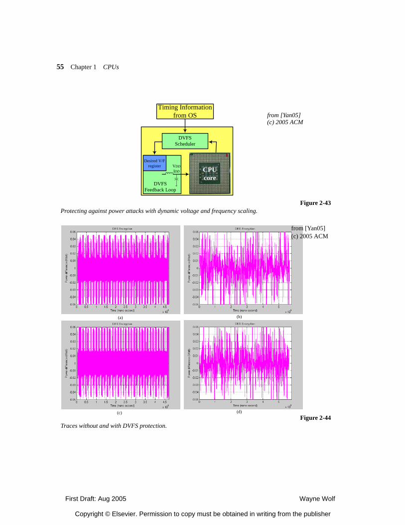
First Draft: Aug 2005 Wayne Wolf
Copyright © Elsevier. Permission to copy must be obtained in writing from the publisher
55 Chapter 1 CPUs
Figure 2-43Protecting against power attacks with dynamic voltage and frequency scaling.
DVFSFeedback Loop
Desired V/Fregister VDD
IDD
DVFSScheduler
Timing Informationfrom OS
CPUcore
from [Yan05](c) 2005 ACM
(a) (b)
(c) (d)
from [Yan05](c) 2005 ACM
Figure 2-44Traces without and with DVFS protection.
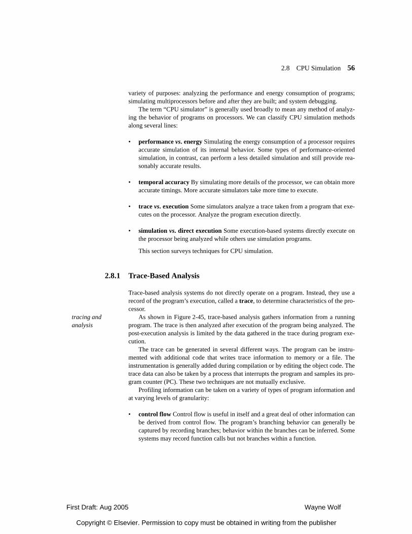
First Draft: Aug 2005 Wayne Wolf
Copyright © Elsevier. Permission to copy must be obtained in writing from the publisher
2.8 CPU Simulation 56
variety of purposes: analyzing the performance and energy consumption of programs;simulating multiprocessors before and after they are built; and system debugging.
The term “CPU simulator” is generally used broadly to mean any method of analyz-ing the behavior of programs on processors. We can classify CPU simulation methodsalong several lines:
• performance vs. energy Simulating the energy consumption of a processor requiresaccurate simulation of its internal behavior. Some types of performance-orientedsimulation, in contrast, can perform a less detailed simulation and still provide rea-sonably accurate results.
• temporal accuracy By simulating more details of the processor, we can obtain moreaccurate timings. More accurate simulators take more time to execute.
• trace vs. execution Some simulators analyze a trace taken from a program that exe-cutes on the processor. Analyze the program execution directly.
• simulation vs. direct execution Some execution-based systems directly execute onthe processor being analyzed while others use simulation programs.
This section surveys techniques for CPU simulation.
2.8.1 Trace-Based Analysis
Trace-based analysis systems do not directly operate on a program. Instead, they use arecord of the program’s execution, called a trace, to determine characteristics of the pro-cessor.
tracing and analysis
As shown in Figure 2-45, trace-based analysis gathers information from a runningprogram. The trace is then analyzed after execution of the program being analyzed. Thepost-execution analysis is limited by the data gathered in the trace during program exe-cution.
The trace can be generated in several different ways. The program can be instru-mented with additional code that writes trace information to memory or a file. Theinstrumentation is generally added during compilation or by editing the object code. Thetrace data can also be taken by a process that interrupts the program and samples its pro-gram counter (PC). These two techniques are not mutually exclusive.
Profiling information can be taken on a variety of types of program information andat varying levels of granularity:
• control flow Control flow is useful in itself and a great deal of other information canbe derived from control flow. The program’s branching behavior can generally becaptured by recording branches; behavior within the branches can be inferred. Somesystems may record function calls but not branches within a function.
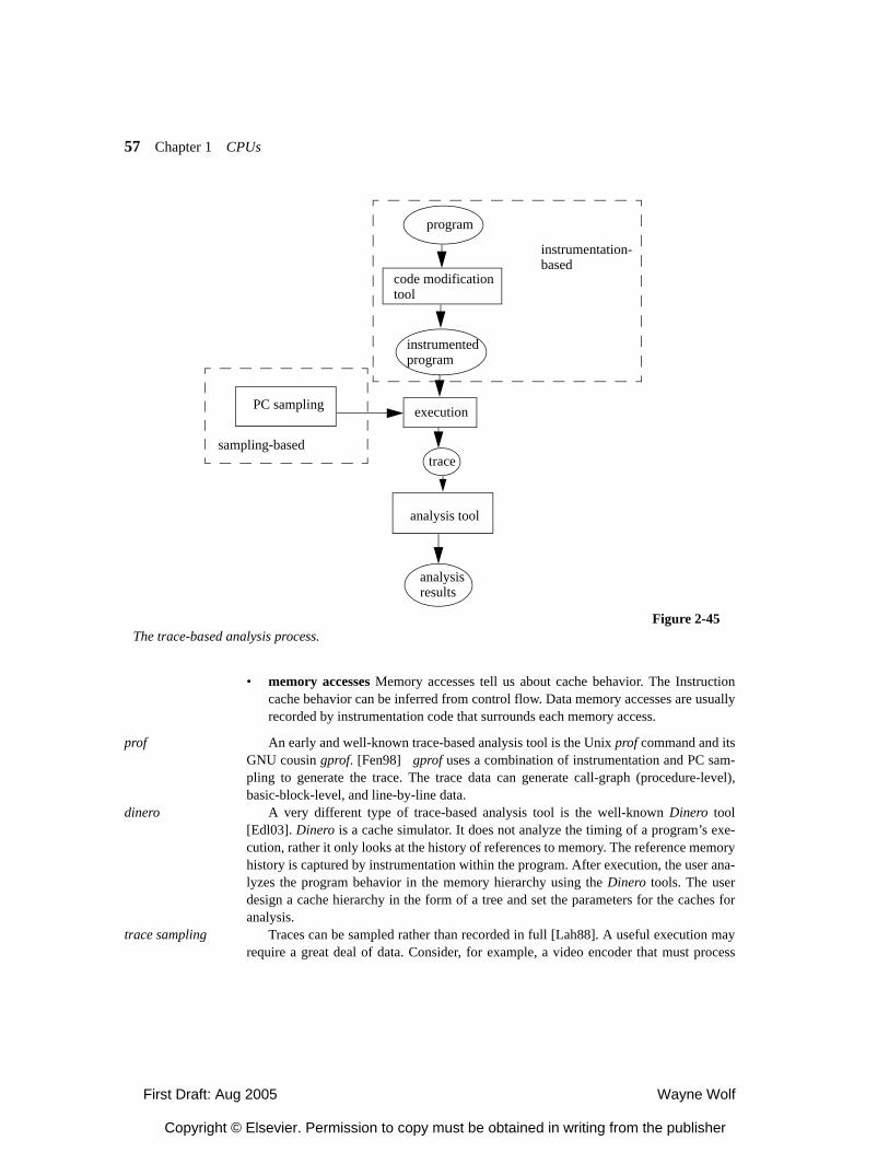
First Draft: Aug 2005 Wayne Wolf
Copyright © Elsevier. Permission to copy must be obtained in writing from the publisher
57 Chapter 1 CPUs
• memory accesses Memory accesses tell us about cache behavior. The Instructioncache behavior can be inferred from control flow. Data memory accesses are usuallyrecorded by instrumentation code that surrounds each memory access.
prof An early and well-known trace-based analysis tool is the Unix prof command and itsGNU cousin gprof. [Fen98] gprof uses a combination of instrumentation and PC sam-pling to generate the trace. The trace data can generate call-graph (procedure-level),basic-block-level, and line-by-line data.
dinero A very different type of trace-based analysis tool is the well-known Dinero tool[Edl03]. Dinero is a cache simulator. It does not analyze the timing of a program’s exe-cution, rather it only looks at the history of references to memory. The reference memoryhistory is captured by instrumentation within the program. After execution, the user ana-lyzes the program behavior in the memory hierarchy using the Dinero tools. The userdesign a cache hierarchy in the form of a tree and set the parameters for the caches foranalysis.
trace sampling Traces can be sampled rather than recorded in full [Lah88]. A useful execution mayrequire a great deal of data. Consider, for example, a video encoder that must process
program
code modificationtool
instrumentedprogram
execution
trace
analysis tool
analysisresults
Figure 2-45The trace-based analysis process.
PC sampling
sampling-based
instrumentation-based
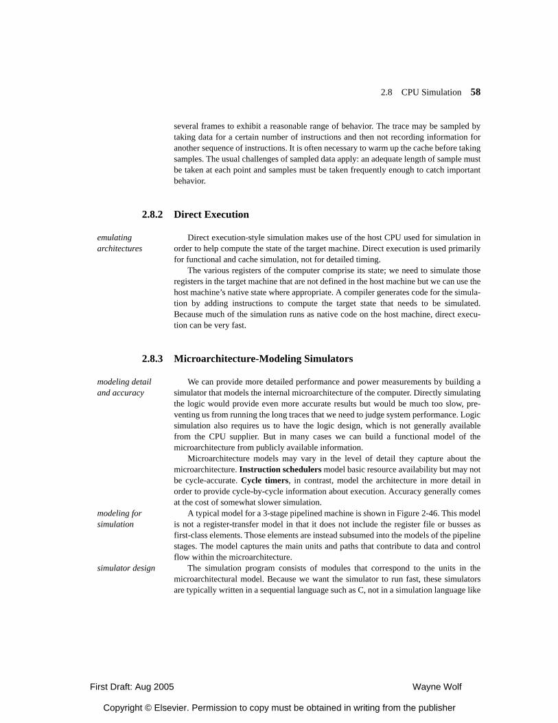
First Draft: Aug 2005 Wayne Wolf
Copyright © Elsevier. Permission to copy must be obtained in writing from the publisher
2.8 CPU Simulation 58
several frames to exhibit a reasonable range of behavior. The trace may be sampled bytaking data for a certain number of instructions and then not recording information foranother sequence of instructions. It is often necessary to warm up the cache before takingsamples. The usual challenges of sampled data apply: an adequate length of sample mustbe taken at each point and samples must be taken frequently enough to catch importantbehavior.
2.8.2 Direct Execution
emulating architectures
Direct execution-style simulation makes use of the host CPU used for simulation inorder to help compute the state of the target machine. Direct execution is used primarilyfor functional and cache simulation, not for detailed timing.
The various registers of the computer comprise its state; we need to simulate thoseregisters in the target machine that are not defined in the host machine but we can use thehost machine’s native state where appropriate. A compiler generates code for the simula-tion by adding instructions to compute the target state that needs to be simulated.Because much of the simulation runs as native code on the host machine, direct execu-tion can be very fast.
2.8.3 Microarchitecture-Modeling Simulators
modeling detail and accuracy
We can provide more detailed performance and power measurements by building asimulator that models the internal microarchitecture of the computer. Directly simulatingthe logic would provide even more accurate results but would be much too slow, pre-venting us from running the long traces that we need to judge system performance. Logicsimulation also requires us to have the logic design, which is not generally availablefrom the CPU supplier. But in many cases we can build a functional model of themicroarchitecture from publicly available information.
Microarchitecture models may vary in the level of detail they capture about themicroarchitecture. Instruction schedulers model basic resource availability but may notbe cycle-accurate. Cycle timers, in contrast, model the architecture in more detail inorder to provide cycle-by-cycle information about execution. Accuracy generally comesat the cost of somewhat slower simulation.
modeling for simulation
A typical model for a 3-stage pipelined machine is shown in Figure 2-46. This modelis not a register-transfer model in that it does not include the register file or busses asfirst-class elements. Those elements are instead subsumed into the models of the pipelinestages. The model captures the main units and paths that contribute to data and controlflow within the microarchitecture.
simulator design The simulation program consists of modules that correspond to the units in themicroarchitectural model. Because we want the simulator to run fast, these simulatorsare typically written in a sequential language such as C, not in a simulation language like
First Draft: Aug 2005 Wayne Wolf
Copyright © Elsevier. Permission to copy must be obtained in writing from the publisher
59 Chapter 1 CPUs
Verilog or VHDL. Simulation languages have mechanisms to ensure that modules areevaluated in the proper order when the simulation state changes; when we write simula-tors in sequential languages, we must design the control flow in the program to ensurethat all the implications of a given state change are properly evaluated.
SimpleScalar SimpleScalar [Sim05] is a well-known toolkit for simulator design. Simplescalarprovides modules that model typical components of CPUs as well as tools for data col-lection. These tools can be put together in various ways, modified, or added to in order tocreate a custom simulator. A machine description file describes the microarchitectureand is used to generate parts of the simulation engine as well as programming tools likedisassemblers.
power simulation Power simulators take cycle-accurate microarchitecture simulators one step furtherin detail. Determining the energy/power consumption of a CPU generally requires evenmore accurate modeling than performance simulation. For example, a cycle-accuratetiming simulator may not directly model the bus. But the bus is a major consumer ofenergy in a microprocessor, so a power simulator needs to model the bus, as well as reg-ister files and other major structural components. In general, a power simulator mostmodel all significant sources of capacitance in the processor since dynamic power con-sumption is directly related to capacitance. However, power simulators must trade-offaccuracy for simulation performance just like other cycle-accurate simulators.
Figure 2-46A microarchitectural model for simulation.
fetch decode execute
I$ IMMU D$ DMMU
main memory

First Draft: Aug 2005 Wayne Wolf
Copyright © Elsevier. Permission to copy must be obtained in writing from the publisher
2.9 CPU Simulation 60
Wattch and SimplePower
The two best-known power simulators are Wattch [Bro00] and SimplePower [Ye00].Both are built on top of SimpleScalar and add capacitance models for the major units inthe microarchitecture.
2.8.4 Automated CPU Design
System designers have long used custom processors to run applications at higher speeds.Custom processors were popular in the 1970’s and 1980’s thanks to bit-slice CPU com-ponents. Chips for data paths and controllers, such as the AMD 2910 series, could becombined and microprogrammed to implement a wide range of instruction sets. Today,custom integrated circuits and FPGAs offer complete freedom to designers who are will-ing to put the effort into creating a CPU architecture for their application. Custom CPUsare often known as application-specific instruction processors (ASIPs) or config-urable processors.
why automate CPU design
Custom CPU design is an area that cries out for methodological and tool support.System designers need help determining what sorts of modifications to the CPU arefruitful. They also need help implementing those modifications. Today, system designershave a wide range of tools available to help them design their own processors.
axes of customization
We can customize processors in many different ways:
• Instruction sets can be adapted to the application.
— New instructions can provide compound sets of existing operations, such as mul-tiply-accumulate.
— Instructions can supply new operations, such as primitives for Viterbi encodingor block motion estimation.
— Instructions that operate on non-standard operand sizes can be added to avoidmasking and reduce energy consumption.
— Instructions not important to the application can be removed.
• Pipelines can be specialized to take into account the characteristics of function unitsused in new instructions, implement specialized branch prediction schemes, etc.
• Memory hierarchy can be modified by adding and removing cache levels, choosinga cache configuration, or choosing the banking scheme in a partitioned memory sys-tem.
• Busses and peripherals can be selected and optimized to meet bandwidth and I/Orequirements.
software tools ASIPs require customized versions of the tool chains that software developers havecome to rely upon. Compilers, assemblers, linkers, debuggers, simulators, and IDEs
2.9
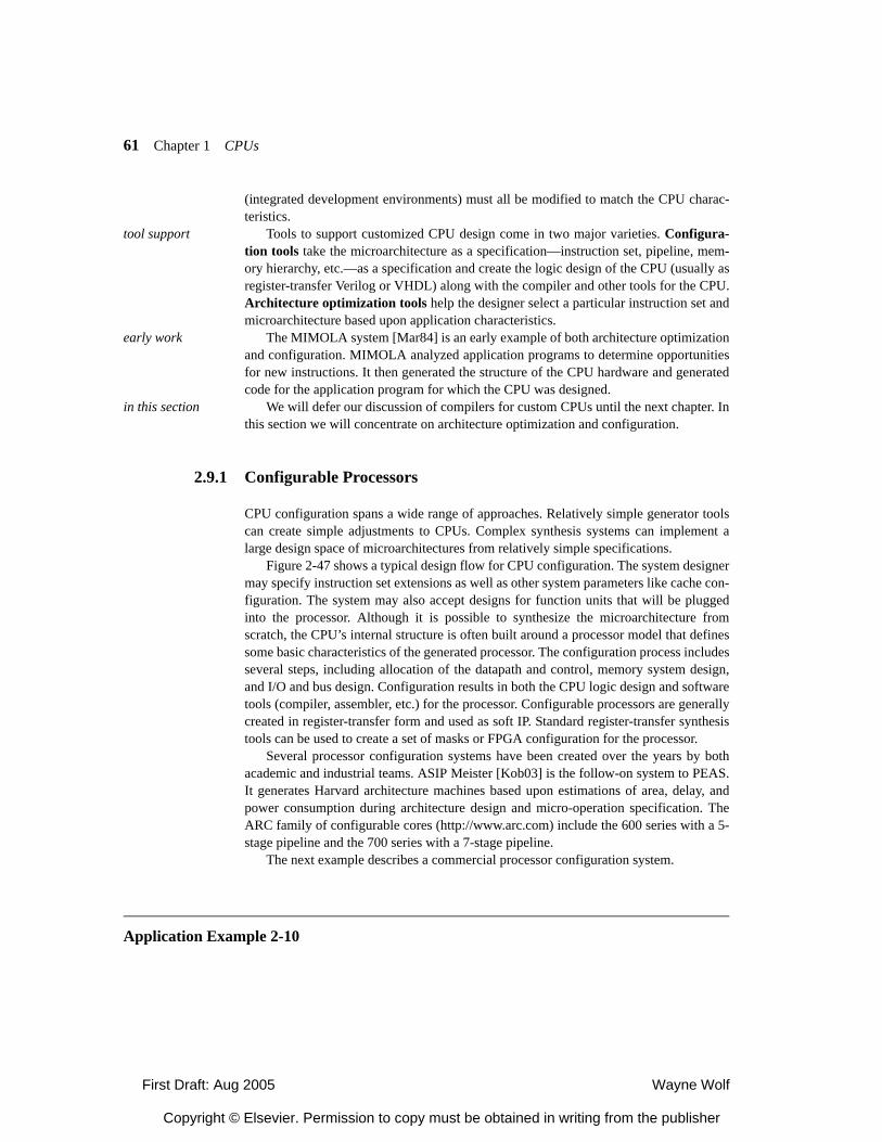
First Draft: Aug 2005 Wayne Wolf
Copyright © Elsevier. Permission to copy must be obtained in writing from the publisher
61 Chapter 1 CPUs
(integrated development environments) must all be modified to match the CPU charac-teristics.
tool support Tools to support customized CPU design come in two major varieties. Configura-tion tools take the microarchitecture as a specification—instruction set, pipeline, mem-ory hierarchy, etc.—as a specification and create the logic design of the CPU (usually asregister-transfer Verilog or VHDL) along with the compiler and other tools for the CPU.Architecture optimization tools help the designer select a particular instruction set andmicroarchitecture based upon application characteristics.
early work The MIMOLA system [Mar84] is an early example of both architecture optimizationand configuration. MIMOLA analyzed application programs to determine opportunitiesfor new instructions. It then generated the structure of the CPU hardware and generatedcode for the application program for which the CPU was designed.
in this section We will defer our discussion of compilers for custom CPUs until the next chapter. Inthis section we will concentrate on architecture optimization and configuration.
2.9.1 Configurable Processors
CPU configuration spans a wide range of approaches. Relatively simple generator toolscan create simple adjustments to CPUs. Complex synthesis systems can implement alarge design space of microarchitectures from relatively simple specifications.
Figure 2-47 shows a typical design flow for CPU configuration. The system designermay specify instruction set extensions as well as other system parameters like cache con-figuration. The system may also accept designs for function units that will be pluggedinto the processor. Although it is possible to synthesize the microarchitecture fromscratch, the CPU’s internal structure is often built around a processor model that definessome basic characteristics of the generated processor. The configuration process includesseveral steps, including allocation of the datapath and control, memory system design,and I/O and bus design. Configuration results in both the CPU logic design and softwaretools (compiler, assembler, etc.) for the processor. Configurable processors are generallycreated in register-transfer form and used as soft IP. Standard register-transfer synthesistools can be used to create a set of masks or FPGA configuration for the processor.
Several processor configuration systems have been created over the years by bothacademic and industrial teams. ASIP Meister [Kob03] is the follow-on system to PEAS.It generates Harvard architecture machines based upon estimations of area, delay, andpower consumption during architecture design and micro-operation specification. TheARC family of configurable cores (http://www.arc.com) include the 600 series with a 5-stage pipeline and the 700 series with a 7-stage pipeline.
The next example describes a commercial processor configuration system.
Application Example 2-10
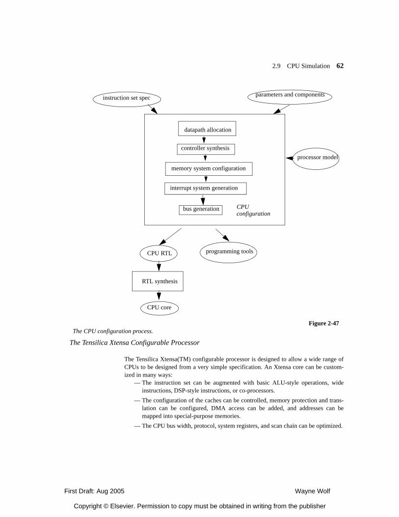
First Draft: Aug 2005 Wayne Wolf
Copyright © Elsevier. Permission to copy must be obtained in writing from the publisher
2.9 CPU Simulation 62
The Tensilica Xtensa Configurable Processor
The Tensilica Xtensa(TM) configurable processor is designed to allow a wide range ofCPUs to be designed from a very simple specification. An Xtensa core can be custom-ized in many ways:
— The instruction set can be augmented with basic ALU-style operations, wideinstructions, DSP-style instructions, or co-processors.
— The configuration of the caches can be controlled, memory protection and trans-lation can be configured, DMA access can be added, and addresses can bemapped into special-purpose memories.
— The CPU bus width, protocol, system registers, and scan chain can be optimized.
instruction set spec
processor model
parameters and components
CPU RTL programming tools
RTL synthesis
CPU core
Figure 2-47The CPU configuration process.
datapath allocation
controller synthesis
memory system configuration
interrupt system generation
bus generation CPUconfiguration
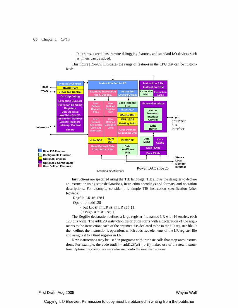
First Draft: Aug 2005 Wayne Wolf
Copyright © Elsevier. Permission to copy must be obtained in writing from the publisher
63 Chapter 1 CPUs
— Interrupts, exceptions, remote debugging features, and standard I/O devices suchas timers can be added.
This figure [Row05] illustrates the range of features in the CPU that can be custom-ized:
Instructions are specified using the TIE language. TIE allows the designer to declarean instruction using state declarations, instruction encodings and formats, and operationdescriptions. For example, consider this simple TIE instruction specification (afterRowen):
Regfile LR 16 128 lOperation add128
{ out LR sr, in LR ss, in LR st } {}{ assign sr = st + ss; }
The Regfile declaration defines a large register file named LR with 16 entries, each128 bits wide. The add128 instruction description starts with a declaration of the argu-ments to the instruction; each of the arguments is declared to be in the LR register file. Itthen defines the instruction’s operation, which adds two elements of the LR register fileand assigns it to a third register in LR.
New instructions may be used in programs with intrinsic calls that map onto instruc-tions. For example, the code out[i] = add128(a[i], b[i]) makes use of the new instruc-tion. Optimizing compilers may also map onto the new instructions.
External Interface
Base ISA FeatureConfigurable FunctionOptional Function
User Defined Features Optional & Configurable
JTAG Extended Instruction Align, Decode,
Dispatch
Xtensa Processor InterfaceControl
Write Buffer
XtensaLocal Memory Interface
TRACE PortJTAG Tap Control
On Chip Debug
User Defined
Execution Units and Interfaces
Instruction Decode/Dispat
ch
Base ALU
Floating Point
VLIW DSP
MAC 16 DSPMUL 16/32
User Defined Register
Files
Instruction Fetch / PC
Data Load/Store
Unit
Data ROMs
Data RAMs
DataCache
DataMMU
User Defined
Execution Units
User Defined Register
Files
VLIW DSP
Base Register File
User Defined Execution Unit
VLIW DSP
Processor Controls
Interrupt Control
Data Address Watch Registers
Instruction Address Watch Registers
Timers
Used Defined Data Load/Store Units
Instruction ROMInstruction RAM
InstructionCache
Instruction MMU
PIF
Exception SupportException Handling
Registers
Trace
Interrupts
Tensilica ConfidentialRowen DAC slide 20
processorbus interface
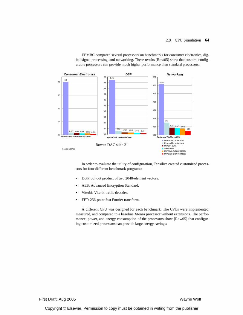
First Draft: Aug 2005 Wayne Wolf
Copyright © Elsevier. Permission to copy must be obtained in writing from the publisher
2.9 CPU Simulation 64
EEMBC compared several processors on benchmarks for consumer electronics, dig-ital signal processing, and networking. These results [Row05] show that custom, config-urable processors can provide much higher performance than standard processors:
In order to evaluate the utility of configuration, Tensilica created customized proces-sors for four different benchmark programs:
• DotProd: dot product of two 2048-element vectors.
• AES: Advanced Encryption Standard.
• Viterbi: Viterbi trellis decoder.
• FFT: 256-point fast Fourier transform.
A different CPU was designed for each benchmark. The CPUs were implemented,measured, and compared to a baseline Xtensa processor without extensions. The perfor-mance, power, and energy consumption of the processors show [Row05] that configur-ing customized processors can provide large energy savings:
2.0
0.087 0.080 0.059 0.058 0.0390.0
0.5
1.0
1.5
2.0
Optimized ConsumerMarks/MHz
0.473
0.030.016 0.013 0.0110.017
0.0
0.1
0.1
0.2
0.2
0.3
0.3
0.4
0.4
0.5
0.5
Optimized TeleMarks/MHz
0.123
0.03
0.018 0.017 0.0160.01
0.00
0.02
0.04
0.06
0.08
0.10
0.12
0.14
Extensible optimized Extensible out-of-box MIPS64 20Kc ARM1020E MIPS64b (NEC VR5000) MIPS32b (NEC VR4122)
Optimized NetMarks/MHz
Source: EEMBC
Consumer Electronics DSP Networking
Rowen DAC slide 21
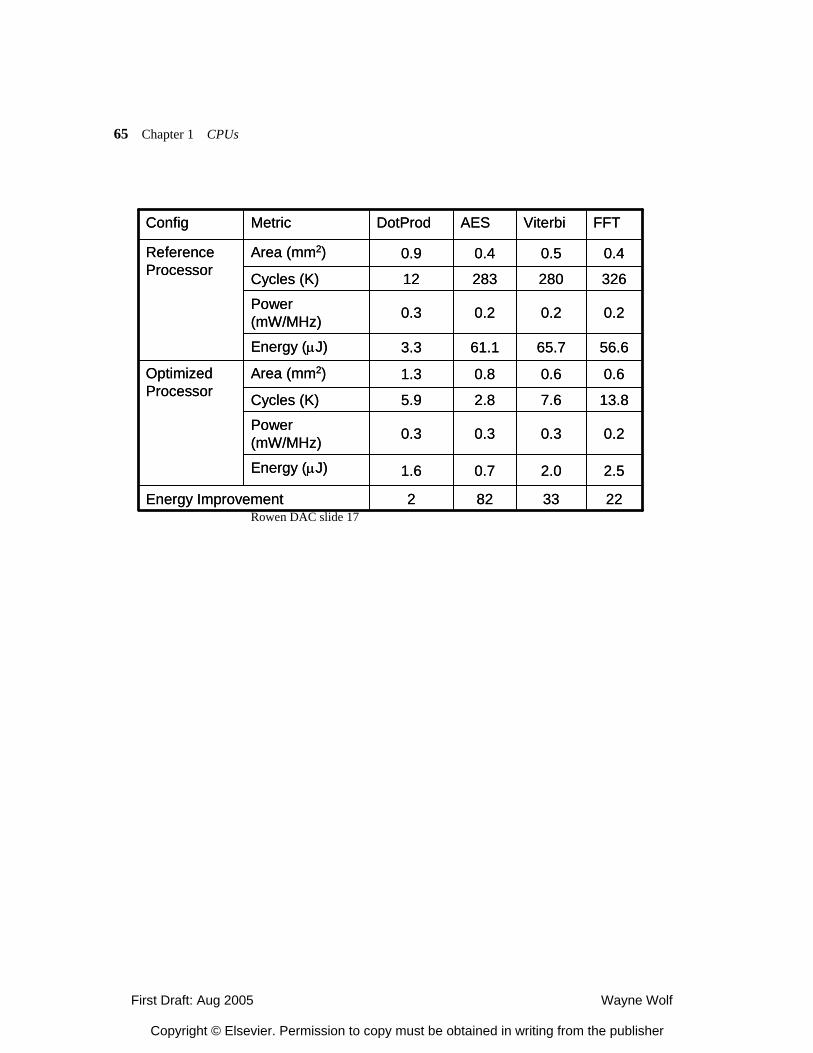
First Draft: Aug 2005 Wayne Wolf
Copyright © Elsevier. Permission to copy must be obtained in writing from the publisher
65 Chapter 1 CPUs
2233822Energy Improvement
2.52.00.71.6Energy (µJ)
0.20.30.30.3Power (mW/MHz)
13.87.62.85.9Cycles (K)
0.60.60.81.3Area (mm2)Optimized Processor
56.665.761.13.3Energy (µJ)
0.20.20.20.3Power (mW/MHz)
32628028312Cycles (K)
0.40.50.40.9Area (mm2)Reference Processor
FFTViterbiAESDotProdMetricConfig
2233822Energy Improvement
2.52.00.71.6Energy (µJ)
0.20.30.30.3Power (mW/MHz)
13.87.62.85.9Cycles (K)
0.60.60.81.3Area (mm2)Optimized Processor
56.665.761.13.3Energy (µJ)
0.20.20.20.3Power (mW/MHz)
32628028312Cycles (K)
0.40.50.40.9Area (mm2)Reference Processor
FFTViterbiAESDotProdMetricConfig
Rowen DAC slide 17
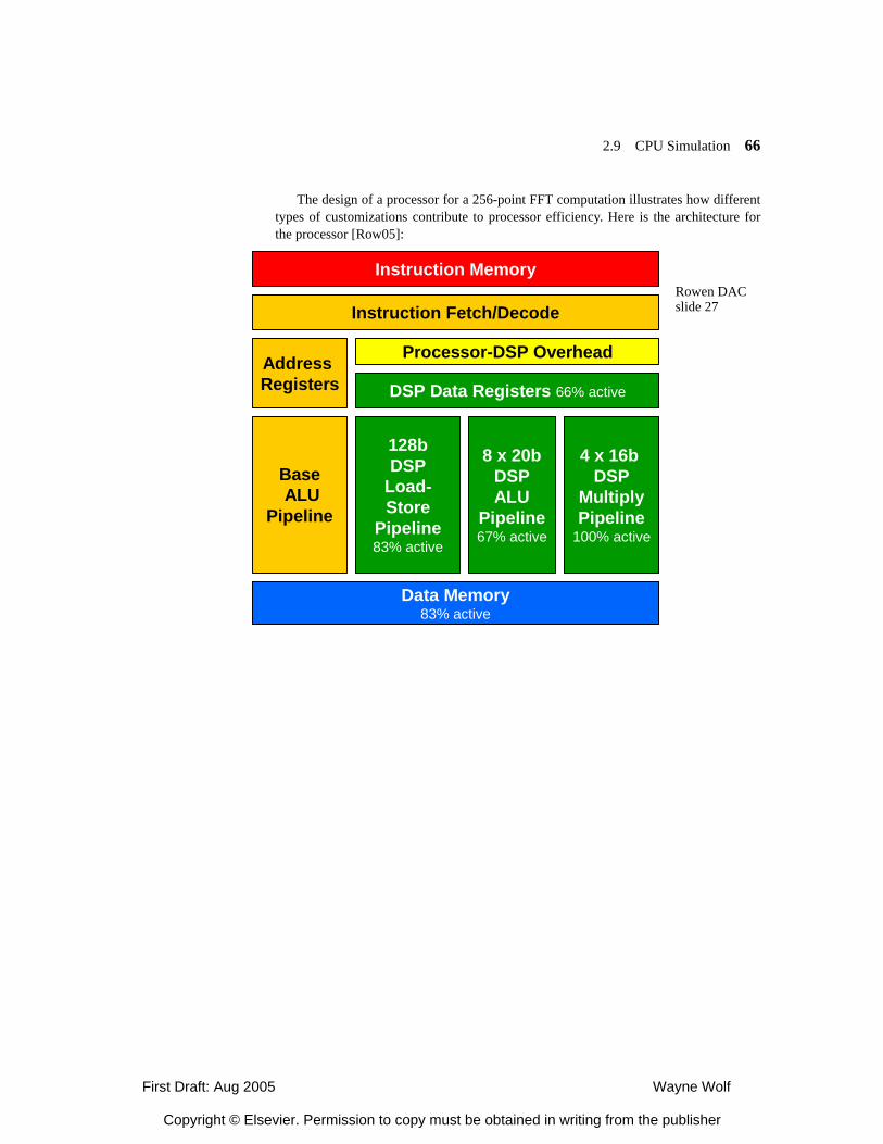
First Draft: Aug 2005 Wayne Wolf
Copyright © Elsevier. Permission to copy must be obtained in writing from the publisher
2.9 CPU Simulation 66
The design of a processor for a 256-point FFT computation illustrates how differenttypes of customizations contribute to processor efficiency. Here is the architecture forthe processor [Row05]:
Instruction Memory
Instruction Fetch/Decode
Address Registers
BaseALU
Pipeline
128bDSP
Load-Store
Pipeline83% active
8 x 20bDSPALU
Pipeline67% active
4 x 16b DSP
MultiplyPipeline
100% active
Processor-DSP Overhead
Data Memory83% active
DSP Data Registers 66% active
Rowen DACslide 27
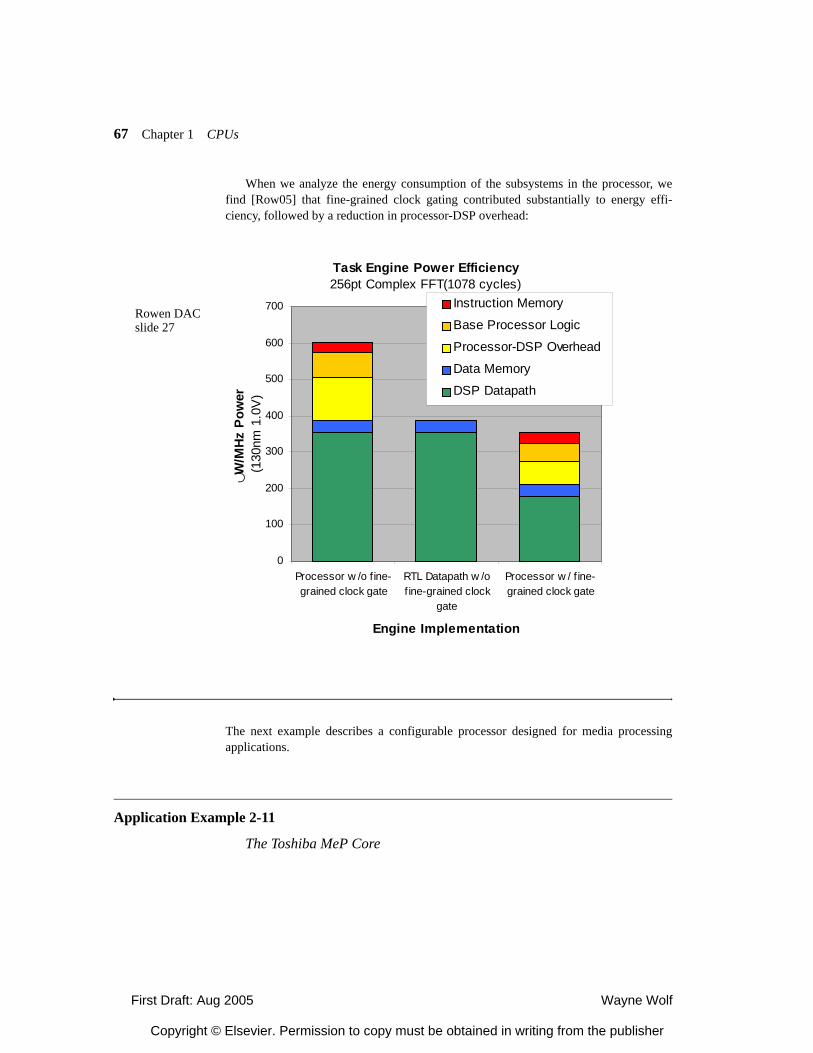
First Draft: Aug 2005 Wayne Wolf
Copyright © Elsevier. Permission to copy must be obtained in writing from the publisher
67 Chapter 1 CPUs
When we analyze the energy consumption of the subsystems in the processor, wefind [Row05] that fine-grained clock gating contributed substantially to energy effi-ciency, followed by a reduction in processor-DSP overhead:
The next example describes a configurable processor designed for media processingapplications.
Application Example 2-11
The Toshiba MeP Core
Task Engine Power Efficiency256pt Complex FFT(1078 cycles)
0
100
200
300
400
500
600
700
Processor w /o fine-grained clock gate
RTL Datapath w /ofine-grained clock
gate
Processor w / f ine-grained clock gate
Engine Implementation
∪W/M
Hz P
ower
(1
30nm
1.0
V)
Instruction Memory
Base Processor Logic
Processor-DSP Overhead
Data Memory
DSP Datapath
Rowen DACslide 27
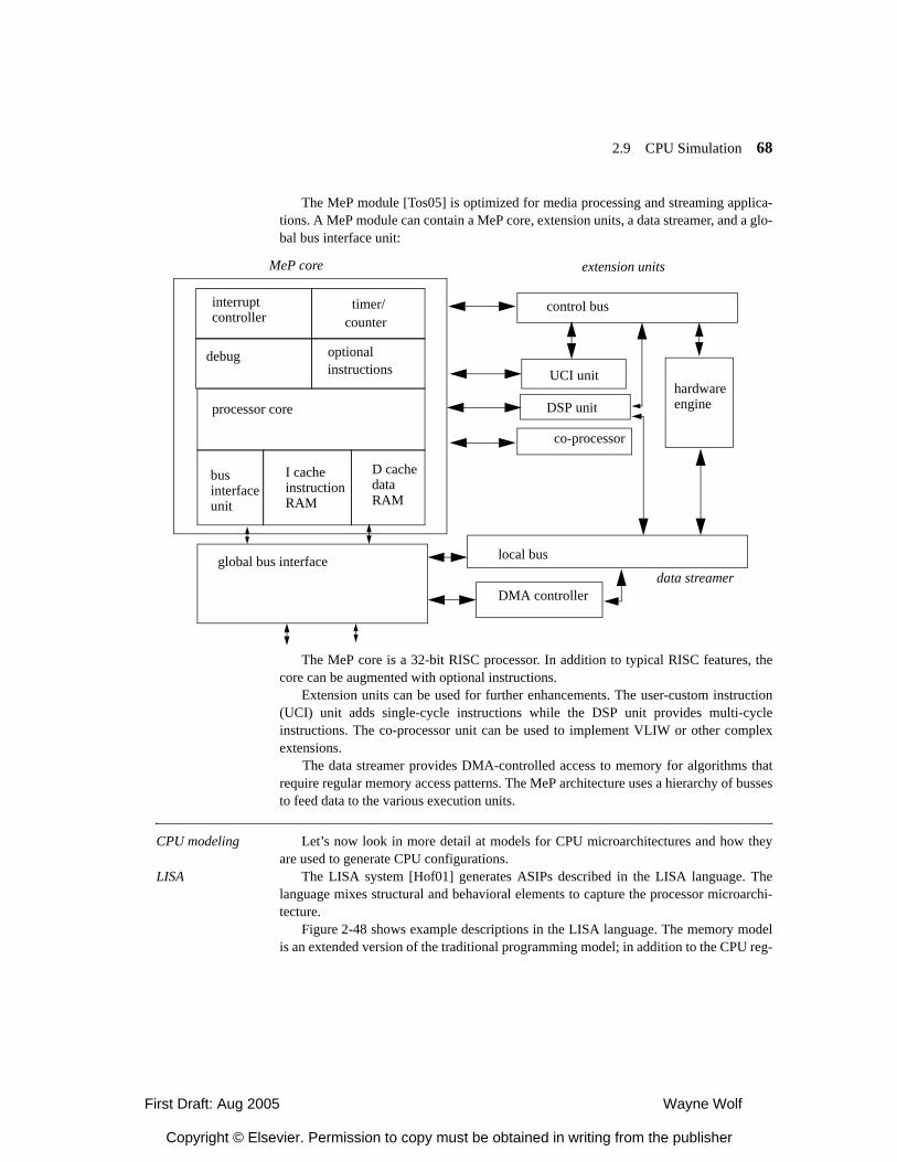
First Draft: Aug 2005 Wayne Wolf
Copyright © Elsevier. Permission to copy must be obtained in writing from the publisher
2.9 CPU Simulation 68
The MeP module [Tos05] is optimized for media processing and streaming applica-tions. A MeP module can contain a MeP core, extension units, a data streamer, and a glo-bal bus interface unit:
The MeP core is a 32-bit RISC processor. In addition to typical RISC features, thecore can be augmented with optional instructions.
Extension units can be used for further enhancements. The user-custom instruction(UCI) unit adds single-cycle instructions while the DSP unit provides multi-cycleinstructions. The co-processor unit can be used to implement VLIW or other complexextensions.
The data streamer provides DMA-controlled access to memory for algorithms thatrequire regular memory access patterns. The MeP architecture uses a hierarchy of bussesto feed data to the various execution units.
CPU modeling Let’s now look in more detail at models for CPU microarchitectures and how theyare used to generate CPU configurations.
LISA The LISA system [Hof01] generates ASIPs described in the LISA language. Thelanguage mixes structural and behavioral elements to capture the processor microarchi-tecture.
Figure 2-48 shows example descriptions in the LISA language. The memory modelis an extended version of the traditional programming model; in addition to the CPU reg-
processor core
debug optionalinstructions
interruptcontroller
timer/counter
businterfaceunit
I cacheinstructionRAM
D cachedataRAM
control bus
hardwareengine
UCI unit
DSP unit
co-processor
local bus
DMA controller
global bus interface
MeP core extension units
data streamer
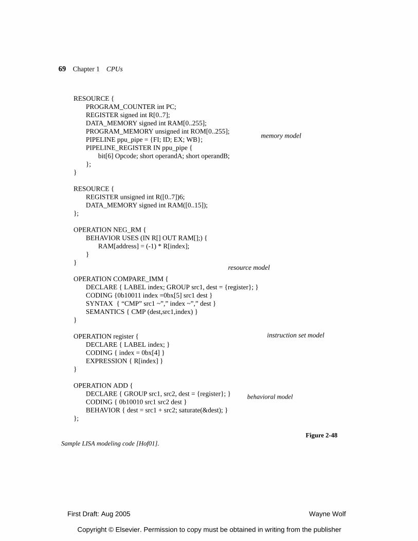
First Draft: Aug 2005 Wayne Wolf
Copyright © Elsevier. Permission to copy must be obtained in writing from the publisher
69 Chapter 1 CPUs
RESOURCE {PROGRAM_COUNTER int PC;REGISTER signed int R[0..7];DATA_MEMORY signed int RAM[0..255];PROGRAM_MEMORY unsigned int ROM[0..255];PIPELINE ppu_pipe = {FI; ID; EX; WB};PIPELINE_REGISTER IN ppu_pipe {
bit[6] Opcode; short operandA; short operandB;};
}
RESOURCE {REGISTER unsigned int R([0..7])6;DATA_MEMORY signed int RAM([0..15]);
};
OPERATION NEG_RM {BEHAVIOR USES (IN R[] OUT RAM[];) {
RAM[address] = (-1) * R[index];}
}
OPERATION COMPARE_IMM {DECLARE { LABEL index; GROUP src1, dest = {register}; }CODING {0b10011 index =0bx[5] src1 dest }SYNTAX { “CMP” src1 ~”,” index ~”,” dest }SEMANTICS { CMP (dest,src1,index) }
}
OPERATION register {DECLARE { LABEL index; }CODING { index = 0bx[4] }EXPRESSION { R[index] }
}
OPERATION ADD {DECLARE { GROUP src1, src2, dest = {register}; }CODING { 0b10010 src1 src2 dest }BEHAVIOR { dest = src1 + src2; saturate(&dest); }
};
memory model
resource model
instruction set model
Figure 2-48Sample LISA modeling code [Hof01].
behavioral model
First Draft: Aug 2005 Wayne Wolf
Copyright © Elsevier. Permission to copy must be obtained in writing from the publisher
2.9 CPU Simulation 70
isters, it also specifies other memories in the system. The resource model describes hard-ware resources as well as constraints on the usage of those resources. The USES clauseinside an OPERATION specifies what resources are used by that operation. The instruc-tion set model describes the assembly syntax, instruction coding, and the function ofinstructions. The behavioral model is used to generate the simulator; it relates hardwarestructures to the operations they perform. Timing information comes from several partsof the model: the PIPELINE declaration in the resource section gives the structure of thepipeline; the IN keyword as part of an OPERATION statement assigns operations topipeline stages; the ACTIVATION keyword in the OPERATION section launches otheroperations performed during the instruction. In addition, an ENTITY statement allowsoperations to be grouped together into functional units, such as an ALU made from sev-eral arithmetic and logical operators.
LISA hardware generation
LISA generates VHDL for the processor as a hierarchy of entities. The memory, reg-ister, and pipeline are the top-level entities. Each pipeline stage is an entity used as acomponent of the pipeline, while stage components like ALUs are described as entities.Groupings of operations into functional units are implemented as VHDL entities.
LISA generates VHDL for only some of the processor, leaving some entities to beimplemented by hand. Some of the processor components must be carefully coded toensure that register-transfer and physical synthesis will provide acceptable power andtiming. LISA generates HDL code for the top-level entities (pipeline/registers/memory),the instruction decoder, and the pipeline decoder.
PEAS/ASIP Meister
PEAS-III [Ito00,Sas01] synthesizes a processor based upon five types of descriptionfrom the designer:
• Architectural parameters for number of pipeline stages, number of branch delayslots, etc.
• Declaration of function units to be used to implement micro-operations.
• Instruction format definitions.
• Definitions of interrupt conditions and timing.
• Descriptions of instructions and interrupts in terms of micro-operations.
PEAS pipeline structure
Figure 2-49 shows the model used by PEAS-III for a single pipeline stage. The data-path portion of a stage can include one or more function units that implement operations;a function unit may take one or more clock cycles to complete. Each stage has its owncontroller that determines how the function units are used and when data moves forward.The datapath and controller both have registers that present their results to the next stage.
A pipeline stage controller may be in either the valid or invalid state. A stage maybecome invalid because of interrupts or other disruptions to the input of the instructionflow. A stage may also become invalid due to a multi-cycle operation, a branch, or otherdisruptions during the middle of instruction operation.
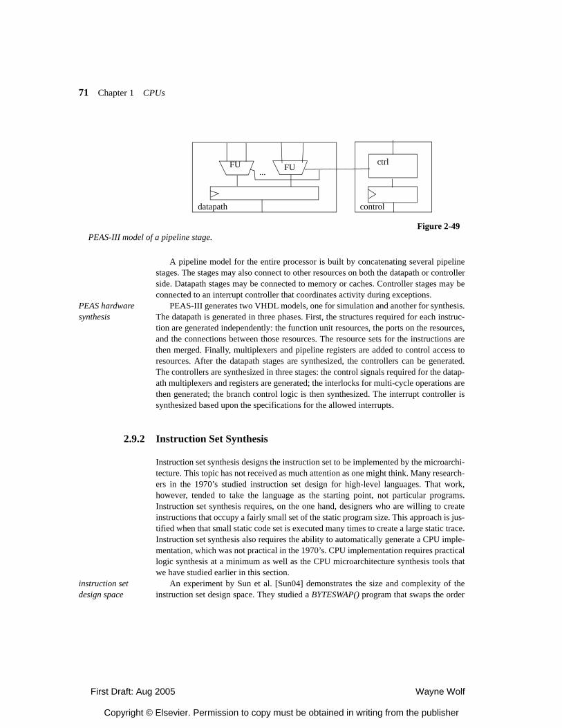
First Draft: Aug 2005 Wayne Wolf
Copyright © Elsevier. Permission to copy must be obtained in writing from the publisher
71 Chapter 1 CPUs
A pipeline model for the entire processor is built by concatenating several pipelinestages. The stages may also connect to other resources on both the datapath or controllerside. Datapath stages may be connected to memory or caches. Controller stages may beconnected to an interrupt controller that coordinates activity during exceptions.
PEAS hardware synthesis
PEAS-III generates two VHDL models, one for simulation and another for synthesis.The datapath is generated in three phases. First, the structures required for each instruc-tion are generated independently: the function unit resources, the ports on the resources,and the connections between those resources. The resource sets for the instructions arethen merged. Finally, multiplexers and pipeline registers are added to control access toresources. After the datapath stages are synthesized, the controllers can be generated.The controllers are synthesized in three stages: the control signals required for the datap-ath multiplexers and registers are generated; the interlocks for multi-cycle operations arethen generated; the branch control logic is then synthesized. The interrupt controller issynthesized based upon the specifications for the allowed interrupts.
2.9.2 Instruction Set Synthesis
Instruction set synthesis designs the instruction set to be implemented by the microarchi-tecture. This topic has not received as much attention as one might think. Many research-ers in the 1970’s studied instruction set design for high-level languages. That work,however, tended to take the language as the starting point, not particular programs.Instruction set synthesis requires, on the one hand, designers who are willing to createinstructions that occupy a fairly small set of the static program size. This approach is jus-tified when that small static code set is executed many times to create a large static trace.Instruction set synthesis also requires the ability to automatically generate a CPU imple-mentation, which was not practical in the 1970’s. CPU implementation requires practicallogic synthesis at a minimum as well as the CPU microarchitecture synthesis tools thatwe have studied earlier in this section.
instruction set design space
An experiment by Sun et al. [Sun04] demonstrates the size and complexity of theinstruction set design space. They studied a BYTESWAP() program that swaps the order
...FU FU ctrl
datapath control
Figure 2-49PEAS-III model of a pipeline stage.
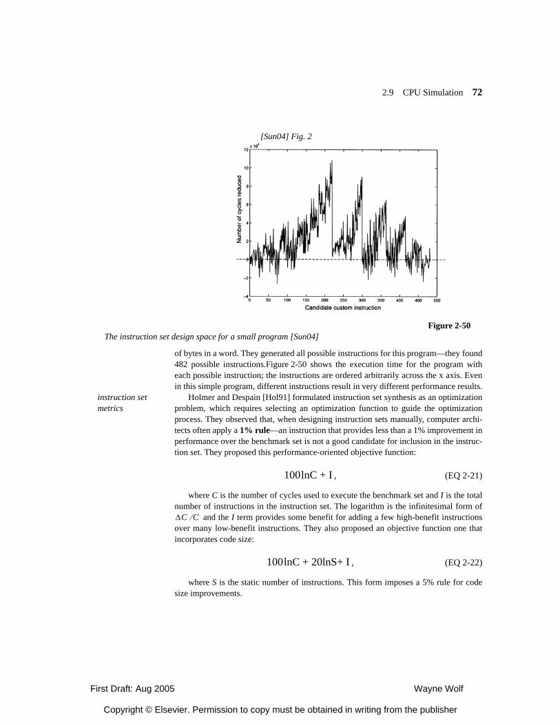
First Draft: Aug 2005 Wayne Wolf
Copyright © Elsevier. Permission to copy must be obtained in writing from the publisher
2.9 CPU Simulation 72
of bytes in a word. They generated all possible instructions for this program—they found482 possible instructions.Figure 2-50 shows the execution time for the program witheach possible instruction; the instructions are ordered arbitrarily across the x axis. Evenin this simple program, different instructions result in very different performance results.
instruction set metrics
Holmer and Despain [Hol91] formulated instruction set synthesis as an optimizationproblem, which requires selecting an optimization function to guide the optimizationprocess. They observed that, when designing instruction sets manually, computer archi-tects often apply a 1% rule—an instruction that provides less than a 1% improvement inperformance over the benchmark set is not a good candidate for inclusion in the instruc-tion set. They proposed this performance-oriented objective function:
, (EQ 2-21)
where C is the number of cycles used to execute the benchmark set and I is the totalnumber of instructions in the instruction set. The logarithm is the infinitesimal form of
and the I term provides some benefit for adding a few high-benefit instructionsover many low-benefit instructions. They also proposed an objective function one thatincorporates code size:
, (EQ 2-22)
where S is the static number of instructions. This form imposes a 5% rule for codesize improvements.
Figure 2-50The instruction set design space for a small program [Sun04]
[Sun04] Fig. 2
100lnC + I
∆C C⁄
100lnC + 20lnS+ I
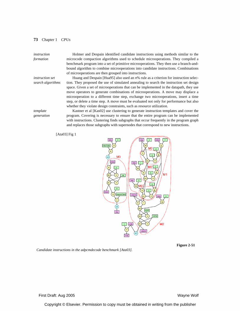
First Draft: Aug 2005 Wayne Wolf
Copyright © Elsevier. Permission to copy must be obtained in writing from the publisher
73 Chapter 1 CPUs
instruction formation
Holmer and Despain identified candidate instructions using methods similar to themicrocode compaction algorithms used to schedule microoperations. They compiled abenchmark program into a set of primitive microoperations. They then use a branch-and-bound algorithm to combine microoperations into candidate instructions. Combinationsof microoperations are then grouped into instructions.
instruction set search algorithms
Huang and Despain [Hua95] also used an n% rule as a criterion for instruction selec-tion. They proposed the use of simulated annealing to search the instruction set designspace. Given a set of microoperations that can be implemented in the datapath, they usemove operators to generate combinations of microoperations. A move may displace amicrooperation to a different time step, exchange two microoperations, insert a timestep, or delete a time step. A move must be evaluated not only for performance but alsowhether they violate design constraints, such as resource utilization.
template generation
Kastner et al [Kas02] use clustering to generate instruction templates and cover theprogram. Covering is necessary to ensure that the entire program can be implementedwith instructions. Clustering finds subgraphs that occur frequently in the program graphand replaces those subgraphs with supernodes that correspond to new instructions.
[Ata03] Fig 1
Figure 2-51Candidate instructions in the adpcmdecode benchmark [Ata03].
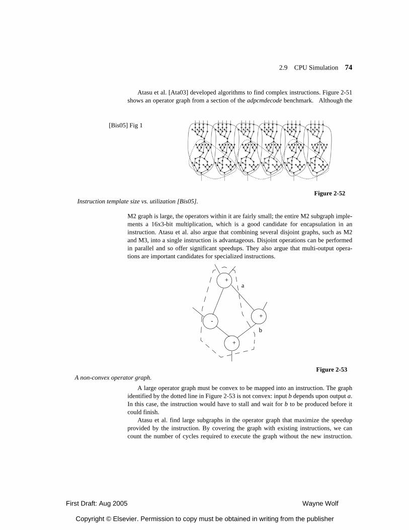
First Draft: Aug 2005 Wayne Wolf
Copyright © Elsevier. Permission to copy must be obtained in writing from the publisher
2.9 CPU Simulation 74
Atasu et al. [Ata03] developed algorithms to find complex instructions. Figure 2-51shows an operator graph from a section of the adpcmdecode benchmark. Although the
M2 graph is large, the operators within it are fairly small; the entire M2 subgraph imple-ments a 16x3-bit multiplication, which is a good candidate for encapsulation in aninstruction. Atasu et al. also argue that combining several disjoint graphs, such as M2and M3, into a single instruction is advantageous. Disjoint operations can be performedin parallel and so offer significant speedups. They also argue that multi-output opera-tions are important candidates for specialized instructions.
A large operator graph must be convex to be mapped into an instruction. The graphidentified by the dotted line in Figure 2-53 is not convex: input b depends upon output a.In this case, the instruction would have to stall and wait for b to be produced before itcould finish.
Atasu et al. find large subgraphs in the operator graph that maximize the speedupprovided by the instruction. By covering the graph with existing instructions, we cancount the number of cycles required to execute the graph without the new instruction.
[Bis05] Fig 1
Figure 2-52Instruction template size vs. utilization [Bis05].
+
+-
+
Figure 2-53A non-convex operator graph.
a
b
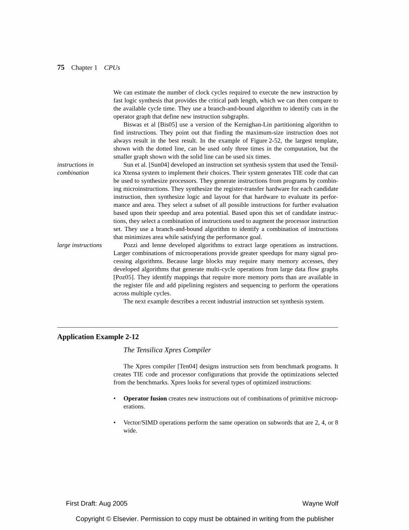
First Draft: Aug 2005 Wayne Wolf
Copyright © Elsevier. Permission to copy must be obtained in writing from the publisher
75 Chapter 1 CPUs
We can estimate the number of clock cycles required to execute the new instruction byfast logic synthesis that provides the critical path length, which we can then compare tothe available cycle time. They use a branch-and-bound algorithm to identify cuts in theoperator graph that define new instruction subgraphs.
Biswas et al [Bis05] use a version of the Kernighan-Lin partitioning algorithm tofind instructions. They point out that finding the maximum-size instruction does notalways result in the best result. In the example of Figure 2-52, the largest template,shown with the dotted line, can be used only three times in the computation, but thesmaller graph shown with the solid line can be used six times.
instructions in combination
Sun et al. [Sun04] developed an instruction set synthesis system that used the Tensil-ica Xtensa system to implement their choices. Their system generates TIE code that canbe used to synthesize processors. They generate instructions from programs by combin-ing microinstructions. They synthesize the register-transfer hardware for each candidateinstruction, then synthesize logic and layout for that hardware to evaluate its perfor-mance and area. They select a subset of all possible instructions for further evaluationbased upon their speedup and area potential. Based upon this set of candidate instruc-tions, they select a combination of instructions used to augment the processor instructionset. They use a branch-and-bound algorithm to identify a combination of instructionsthat minimizes area while satisfying the performance goal.
large instructions Pozzi and Ienne developed algorithms to extract large operations as instructions.Larger combinations of microoperations provide greater speedups for many signal pro-cessing algorithms. Because large blocks may require many memory accesses, theydeveloped algorithms that generate multi-cycle operations from large data flow graphs[Poz05]. They identify mappings that require more memory ports than are available inthe register file and add pipelining registers and sequencing to perform the operationsacross multiple cycles.
The next example describes a recent industrial instruction set synthesis system.
Application Example 2-12
The Tensilica Xpres Compiler
The Xpres compiler [Ten04] designs instruction sets from benchmark programs. Itcreates TIE code and processor configurations that provide the optimizations selectedfrom the benchmarks. Xpres looks for several types of optimized instructions:
• Operator fusion creates new instructions out of combinations of primitive microop-erations.
• Vector/SIMD operations perform the same operation on subwords that are 2, 4, or 8wide.
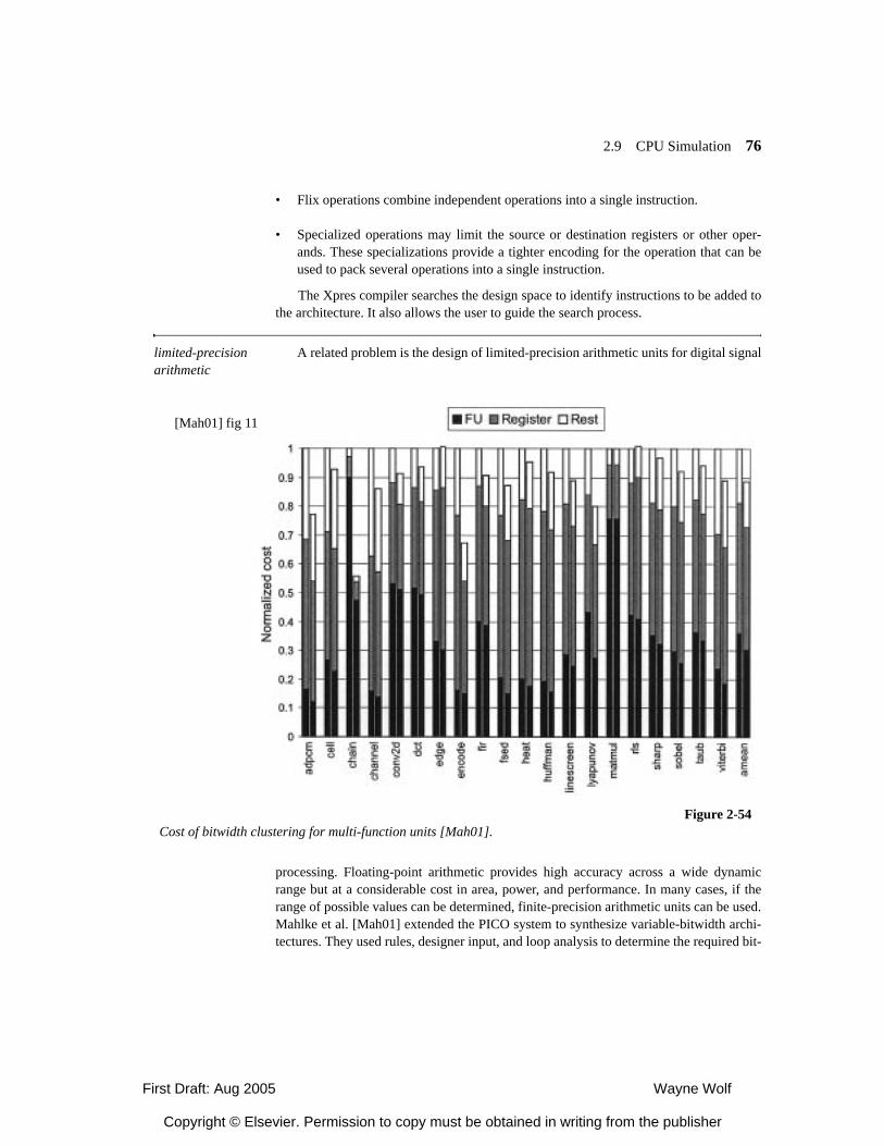
First Draft: Aug 2005 Wayne Wolf
Copyright © Elsevier. Permission to copy must be obtained in writing from the publisher
2.9 CPU Simulation 76
• Flix operations combine independent operations into a single instruction.
• Specialized operations may limit the source or destination registers or other oper-ands. These specializations provide a tighter encoding for the operation that can beused to pack several operations into a single instruction.
The Xpres compiler searches the design space to identify instructions to be added tothe architecture. It also allows the user to guide the search process.
limited-precision arithmetic
A related problem is the design of limited-precision arithmetic units for digital signal
processing. Floating-point arithmetic provides high accuracy across a wide dynamicrange but at a considerable cost in area, power, and performance. In many cases, if therange of possible values can be determined, finite-precision arithmetic units can be used.Mahlke et al. [Mah01] extended the PICO system to synthesize variable-bitwidth archi-tectures. They used rules, designer input, and loop analysis to determine the required bit-
[Mah01] fig 11
Figure 2-54Cost of bitwidth clustering for multi-function units [Mah01].
First Draft: Aug 2005 Wayne Wolf
Copyright © Elsevier. Permission to copy must be obtained in writing from the publisher
77 Chapter 1 CPUs
width of variables. They used def-use analysis to analyze the propagation of bitwidths.They clustered operations together to find a small number of distinct bitwidths to imple-ment the required accuracy with a small number of distinct units. They found that bit-width clustering was particularly effective when operations could be mapped onto multi-function units. The results of their synthesis experiments for a number of benchmarks areshown in Figure 2-54. The right bar shows hardware cost for bitwidth analysis alone,while the left bar shows hardware cost after bitwidth analysis and clustering. Each bardivides hardware cost into registers, function units, and other logic.
The traditional way to determine the dynamic range of an algorithm is by simulation,which requires careful design of the input data set as well as long run times. Fang et al.[Fan03] used affine arithmetic to analyze the numerical characteristics of algorithms.Affine arithmetic models the range of a variable as a linear equation. Terms in the affinemodel can describe the correlation between the ranges of other variables; accurate analy-sis of correlations allows the dynamic range of variables to be tightly bounded.
Summary
CPUs are at the heart of embedded computing. CPUs may be selected from a catalogfor use or they may be custom-designed for the task at hand. A variety of architecturaltechniques are available to optimize CPUs for performance, power consumption, andcost; these techniques can be combined in a number of ways. Processors may bedesigned by hand; a variety of analysis and optimization techniques have been devel-oped to help designers customize processors.
What We Learned
• RISC and DSP approaches can be used in embedded CPUs. The design trade-offs forembedded processors lead to some different conclusions than are typical for general-purpose processors.
• A variety of parallel execution methods can be used; they must be matched to theavailable parallelism.
• Encoding algorithms can be used to efficiently represent signals and instructions inprocessors.
• Embedded processors are prone to many attacks that are not realistic in desktop orserver systems.
• CPU simulation is an important tool for both processor design and software optimi-zation. Several techniques, varying in accuracy and speed, can be used to simulateperformance and energy consumption.
2.10
First Draft: Aug 2005 Wayne Wolf
Copyright © Elsevier. Permission to copy must be obtained in writing from the publisher
2.10 Summary 78
Further Reading
Conte [Con92] describes both CPU simulation and its uses in computer design. The SOSResearch Web site (http://www.sosresearch.org/caale/caalesimulators.html) providesextensive information about CPU simulators. The chapter by Rotenberg and Anantarara-man [Rot04] provides an excellent introduction to embedded CPU architectures. WitoldKinsner has created a good on-line introduction to smart cards at http://www.ee.umani-toba.ca/~kinsner/whatsnew/tutorials/tu1999/smcards.html. This chapter has made refer-ence to United States Patents; all U.S. Patents are available online at http://www.uspto.gov.
Questions
Q2-1 Draw a pipeline diagram for a multiply instruction followed by an addition. Compare tothe pipeline diagram for a multiply-accumulate instruction that requires two clock cyclesto execute. Use pipelines of length:
a. three stages;b. five stages;c. eight stages.
Q2-2 Compare and contrast performing a matrix multiplication using subword parallel instruc-tions and vector instructions. How do the code fragments for the two approaches differ?How do these differences affect performance?
Q2-3 Build a model for a two-way set-associative cache. Show the block-level organization ofthe cache. Create area, delay, and energy models for the cache based upon the formulasfor the block-level model.
Q2-4 Evaluate cache configurations for several block motion estimation algorithms. Themotion estimation search uses a 16 x 16 macroblock and a search area of 25 x 25. Eachpixel is eight bits wide. Consider full search, three-step, and four-step search. The cachesize is fixed at 4096 bytes. Evaluate direct-mapped, 2-way, and 4-way set associativecaches at three different line widths: four bytes, eight bytes, and 16 bytes. Compute thecache miss rate for each case.
Q2-5 Draw a pipeline diagram for a processor that uses a code decompression engine. Notcounting decode, the pipeline includes four stages. Assume that the code decompressionengine requires four cycles for decoding. Show the execution of an addition followed bya branch.
Q2-6 Evaluate the energy savings of bus-invert coding on a data bus for the address sequencesto the array a[10][10], where a starts at address 100s:
a. row-major sequential accesses;

First Draft: Aug 2005 Wayne Wolf
Copyright © Elsevier. Permission to copy must be obtained in writing from the publisher
79 Chapter 1 CPUs
b. column-major sequential access to a;c. diagonal accesses such as those used for JPEG DCT encoding (0,0 -> 1,0 -> 0,1 ->
2,0 -> 1,1 -> 0,2 -> ...).Q2-7 Identify possible instructions in matrix multiplication.
Q2-8 Identify possible instructions in the fast Fourier transform.
Lab Exercises
L2-1 Develop a SimpleScalar model for a DSP with a Harvard architecture and multiply-accu-mulate instruction.
L2-2 Use your SimpleScalar model to compare performance of a matrix multiplication routinewith and without the multiply-accumulate instruction.
L2-3 Use simulation tools to analyze the effects of register file size on performance.
L2-4 Develop a SimpleScalar model for a code decompression engine. Evaluate CPU perfor-mance as the decompression time varies from one to 10 cycles.
191
Chapter
8Networks 8
• General network architectures and the ISO network layers.
• Automotive and aircraft networks.
• Consumer electronics networks.
• Sensor networks.
Introduction
In this chapter we study networks that can be used to build distributed embedded sys-tems. In a distributed embedded system, several processing elements (either micropro-cessors or ASICs) are connected by a network that allows them to communicate. Theapplication is distributed over the processing elements, and some of the work is done ateach node in the network.
There are several reasons to build network-based embedded systems. When the pro-cessing tasks are physically distributed, it may be necessary to put some of the comput-ing power near where the events occur. Consider, for example, an automobile: The shorttime delays required for tasks such as engine control generally mean that at least parts ofthe task are done physically close to the engine. Data reduction is another important rea-son for distributed processing. It may be possible to perform some initial signal process-ing on captured data to reduce its volume—for example, detecting a certain type of eventin a sampled data stream. Reducing the data on a separate processor may significantlyreduce the load on the processor that makes use of that data. Modularity is another moti-vation for network-based design. For instance, when a large system is assembled out ofexisting components, those components may use a network port as a clean interface thatdoes not interfere with the internal operation of the component in ways that using themicroprocessor bus would. A distributed system can also be easier to debug—the micro-processors in one part of the network can be used to probe components in another part ofthe network. Finally, in some cases, networks are used to build fault tolerance into sys-
8.1
First Draft: June 2005 Wayne Wolf
Copyright © Elsevier. Permission to copy must be obtained in writing from the publisher
192 Chapter 8 Networks
tems. Distributed embedded system design is another example of hardware/software co-design, since we must design the network topology as well as the software running onthe network nodes.
Of course, the microprocessor bus is a simple type of network. However, we use theterm network to mean an interconnection scheme that does not provide shared memorycommunication. In the next section, we develop the basic principles of hardware andsoftware architectures for networks. Section 8.3 looks at automotive and aircraft datanetworks. Section 8.4 considers consumer electronics networks. Section 8.5 focuses onsensor networks.
Networking Principles
In this section we will consider network abstractions, then move onto the structure of theInternet stack.
8.2.1 Network Abstractions
Networks are complex systems. Ideally, they provide high-level services while hidingmany of the details of data transmission from the other components in the system. Inorder to help understand (and design) networks, the International Standards Organization(ISO) has developed a seven-layer model for networks known as Open Systems Inter-connection (OSI) models [Sta97A]. Understanding the OSI layers will help us to under-stand the details of real networks.
8.2
First Draft: June 2005 Wayne Wolf
Copyright © Elsevier. Permission to copy must be obtained in writing from the publisher

8.2 Networking Principles 193
The seven layers of the OSI model, shown in Figure 8-1, are intended to cover abroad spectrum of networks and their uses. Some networks may not need the services ofone or more layers because the higher layers may be totally missing or an intermediatelayer may not be necessary. However, any data network should fit into the OSI model.The OSI layers from lowest to highest level of abstraction are described below.
• Physical: The physical layer defines the basic properties of the interface betweensystems, including the physical connections (plugs and wires), electrical properties,basic functions of the electrical and physical components, and the basic proceduresfor exchanging bits.
• Data link: The primary purpose of this layer is error detection and control across asingle link. However, if the network requires multiple hops over several data links,the data link layer does not define the mechanism for data integrity between hops,but only within a single hop.
• Network: This layer defines the basic end-to-end data transmission service. The net-work layer is particularly important in multihop networks.
• Transport: The transport layer defines connection-oriented services that ensurethat data are delivered in the proper order and without errors across multiple links.This layer may also try to optimize network resource utilization.
• Session: A session provides mechanisms for controlling the interaction of end-userservices across a network, such as data grouping and checkpointing.
Figure 8-1 The OSI model layers.
Application
Presentation
Session
Transport
Network
Data link
Physical
End-use interface
Data format
Application dialog control
Connections
End-to-end service
Reliable data transport
Mechanical, electrical
First Draft: June 2005 Wayne Wolf
Copyright © Elsevier. Permission to copy must be obtained in writing from the publisher
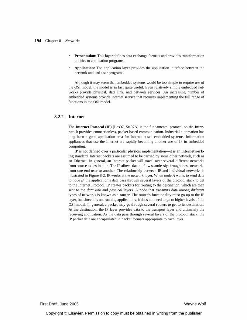
194 Chapter 8 Networks
• Presentation: This layer defines data exchange formats and provides transformationutilities to application programs.
• Application: The application layer provides the application interface between thenetwork and end-user programs.
Although it may seem that embedded systems would be too simple to require use ofthe OSI model, the model is in fact quite useful. Even relatively simple embedded net-works provide physical, data link, and network services. An increasing number ofembedded systems provide Internet service that requires implementing the full range offunctions in the OSI model.
8.2.2 Internet
The Internet Protocol (IP) [Los97, Sta97A] is the fundamental protocol on the Inter-net. It provides connectionless, packet-based communication. Industrial automation haslong been a good application area for Internet-based embedded systems. Informationappliances that use the Internet are rapidly becoming another use of IP in embeddedcomputing.
IP is not defined over a particular physical implementation—it is an internetwork-ing standard. Internet packets are assumed to be carried by some other network, such asan Ethernet. In general, an Internet packet will travel over several different networksfrom source to destination. The IP allows data to flow seamlessly through these networksfrom one end user to another. The relationship between IP and individual networks isillustrated in Figure 8-2. IP works at the network layer. When node A wants to send datato node B, the application’s data pass through several layers of the protocol stack to getto the Internet Protocol. IP creates packets for routing to the destination, which are thensent to the data link and physical layers. A node that transmits data among differenttypes of networks is known as a router. The router’s functionality must go up to the IPlayer, but since it is not running applications, it does not need to go to higher levels of theOSI model. In general, a packet may go through several routers to get to its destination.At the destination, the IP layer provides data to the transport layer and ultimately thereceiving application. As the data pass through several layers of the protocol stack, theIP packet data are encapsulated in packet formats appropriate to each layer.
First Draft: June 2005 Wayne Wolf
Copyright © Elsevier. Permission to copy must be obtained in writing from the publisher
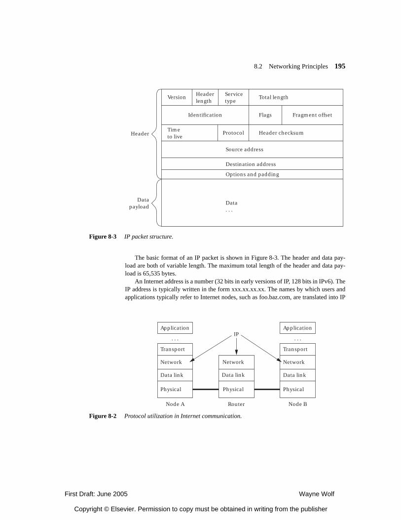
8.2 Networking Principles 195
The basic format of an IP packet is shown in Figure 8-3. The header and data pay-load are both of variable length. The maximum total length of the header and data pay-load is 65,535 bytes.
An Internet address is a number (32 bits in early versions of IP, 128 bits in IPv6). TheIP address is typically written in the form xxx.xx.xx.xx. The names by which users andapplications typically refer to Internet nodes, such as foo.baz.com, are translated into IP
Figure 8-2 Protocol utilization in Internet communication.
Application
Transport
Network
Data link
Network
IP
Physical
Data link
Physical
Node A Node BRouter
Application
. . . . . .
Transport
Network
Data link
Physical
Figure 8-3 IP packet structure.
Version Headerlength
Timeto live
Protocol
Source address
Destination address
Options and padding
Data. . .
Header checksum
Servicetype
Total length
Identification Flags Fragment offset
Header
Datapayload
First Draft: June 2005 Wayne Wolf
Copyright © Elsevier. Permission to copy must be obtained in writing from the publisher
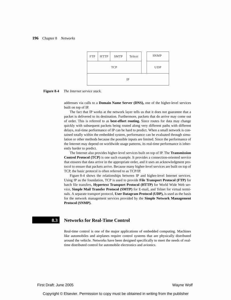
196 Chapter 8 Networks
addresses via calls to a Domain Name Server (DNS), one of the higher-level servicesbuilt on top of IP.
The fact that IP works at the network layer tells us that it does not guarantee that apacket is delivered to its destination. Furthermore, packets that do arrive may come outof order. This is referred to as best-effort routing. Since routes for data may changequickly with subsequent packets being routed along very different paths with differentdelays, real-time performance of IP can be hard to predict. When a small network is con-tained totally within the embedded system, performance can be evaluated through simu-lation or other methods because the possible inputs are limited. Since the performance ofthe Internet may depend on worldwide usage patterns, its real-time performance is inher-ently harder to predict.
The Internet also provides higher-level services built on top of IP. The TransmissionControl Protocol (TCP) is one such example. It provides a connection-oriented servicethat ensures that data arrive in the appropriate order, and it uses an acknowledgment pro-tocol to ensure that packets arrive. Because many higher-level services are built on top ofTCP, the basic protocol is often referred to as TCP/IP.
Figure 8-4 shows the relationships between IP and higher-level Internet services.Using IP as the foundation, TCP is used to provide File Transport Protocol (FTP) forbatch file transfers, Hypertext Transport Protocol (HTTP) for World Wide Web ser-vice, Simple Mail Transfer Protocol (SMTP) for E-mail, and Telnet for virtual termi-nals. A separate transport protocol, User Datagram Protocol (UDP), is used as the basisfor the network management services provided by the Simple Network ManagementProtocol (SNMP).
Networks for Real-Time Control
Real-time control is one of the major applications of embedded computing. Machineslike automobiles and airplanes require control systems that are physically distributedaround the vehicle. Networks have been designed specifically to meet the needs of real-time distributed control for automobile electronics and avionics.
Figure 8-4 The Internet service stack.
FTP HTTP
TCP
IP
UDP
Telnet SNMPSMTP
8.3
First Draft: June 2005 Wayne Wolf
Copyright © Elsevier. Permission to copy must be obtained in writing from the publisher
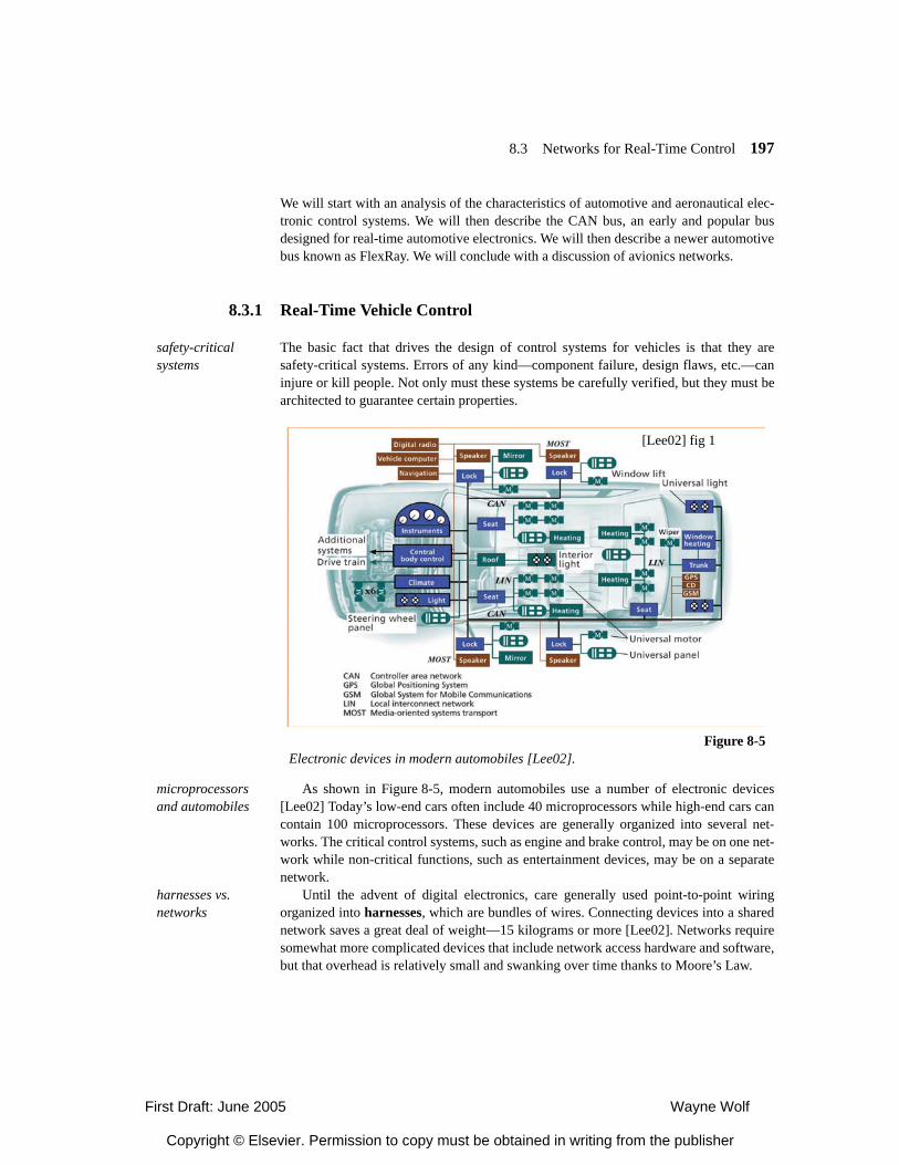
8.3 Networks for Real-Time Control 197
We will start with an analysis of the characteristics of automotive and aeronautical elec-tronic control systems. We will then describe the CAN bus, an early and popular busdesigned for real-time automotive electronics. We will then describe a newer automotivebus known as FlexRay. We will conclude with a discussion of avionics networks.
8.3.1 Real-Time Vehicle Control
safety-critical systems
The basic fact that drives the design of control systems for vehicles is that they aresafety-critical systems. Errors of any kind—component failure, design flaws, etc.—caninjure or kill people. Not only must these systems be carefully verified, but they must bearchitected to guarantee certain properties.
microprocessors and automobiles
As shown in Figure 8-5, modern automobiles use a number of electronic devices[Lee02] Today’s low-end cars often include 40 microprocessors while high-end cars cancontain 100 microprocessors. These devices are generally organized into several net-works. The critical control systems, such as engine and brake control, may be on one net-work while non-critical functions, such as entertainment devices, may be on a separatenetwork.
harnesses vs. networks
Until the advent of digital electronics, care generally used point-to-point wiringorganized into harnesses, which are bundles of wires. Connecting devices into a sharednetwork saves a great deal of weight—15 kilograms or more [Lee02]. Networks requiresomewhat more complicated devices that include network access hardware and software,but that overhead is relatively small and swanking over time thanks to Moore’s Law.
[Lee02] fig 1
Figure 8-5Electronic devices in modern automobiles [Lee02].
First Draft: June 2005 Wayne Wolf
Copyright © Elsevier. Permission to copy must be obtained in writing from the publisher
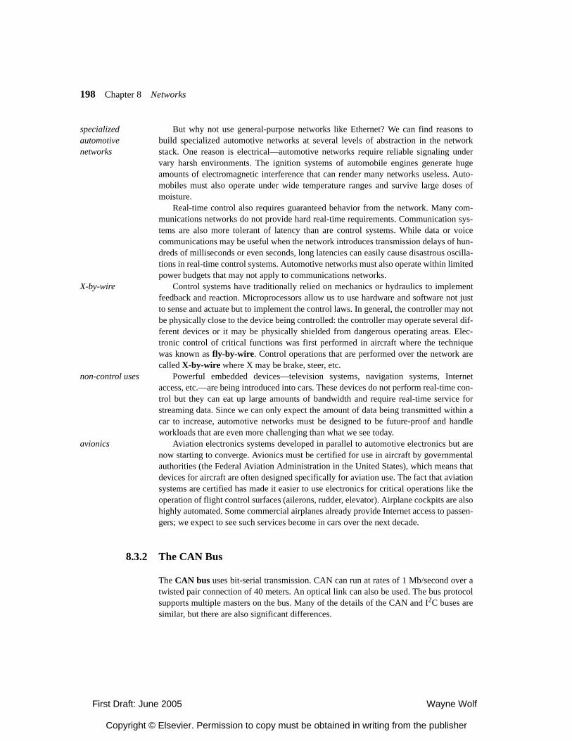
198 Chapter 8 Networks
specialized automotive networks
But why not use general-purpose networks like Ethernet? We can find reasons tobuild specialized automotive networks at several levels of abstraction in the networkstack. One reason is electrical—automotive networks require reliable signaling undervary harsh environments. The ignition systems of automobile engines generate hugeamounts of electromagnetic interference that can render many networks useless. Auto-mobiles must also operate under wide temperature ranges and survive large doses ofmoisture.
Real-time control also requires guaranteed behavior from the network. Many com-munications networks do not provide hard real-time requirements. Communication sys-tems are also more tolerant of latency than are control systems. While data or voicecommunications may be useful when the network introduces transmission delays of hun-dreds of milliseconds or even seconds, long latencies can easily cause disastrous oscilla-tions in real-time control systems. Automotive networks must also operate within limitedpower budgets that may not apply to communications networks.
X-by-wire Control systems have traditionally relied on mechanics or hydraulics to implementfeedback and reaction. Microprocessors allow us to use hardware and software not justto sense and actuate but to implement the control laws. In general, the controller may notbe physically close to the device being controlled: the controller may operate several dif-ferent devices or it may be physically shielded from dangerous operating areas. Elec-tronic control of critical functions was first performed in aircraft where the techniquewas known as fly-by-wire. Control operations that are performed over the network arecalled X-by-wire where X may be brake, steer, etc.
non-control uses Powerful embedded devices—television systems, navigation systems, Internetaccess, etc.—are being introduced into cars. These devices do not perform real-time con-trol but they can eat up large amounts of bandwidth and require real-time service forstreaming data. Since we can only expect the amount of data being transmitted within acar to increase, automotive networks must be designed to be future-proof and handleworkloads that are even more challenging than what we see today.
avionics Aviation electronics systems developed in parallel to automotive electronics but arenow starting to converge. Avionics must be certified for use in aircraft by governmentalauthorities (the Federal Aviation Administration in the United States), which means thatdevices for aircraft are often designed specifically for aviation use. The fact that aviationsystems are certified has made it easier to use electronics for critical operations like theoperation of flight control surfaces (ailerons, rudder, elevator). Airplane cockpits are alsohighly automated. Some commercial airplanes already provide Internet access to passen-gers; we expect to see such services become in cars over the next decade.
8.3.2 The CAN Bus
The CAN bus uses bit-serial transmission. CAN can run at rates of 1 Mb/second over atwisted pair connection of 40 meters. An optical link can also be used. The bus protocolsupports multiple masters on the bus. Many of the details of the CAN and I2C buses aresimilar, but there are also significant differences.
First Draft: June 2005 Wayne Wolf
Copyright © Elsevier. Permission to copy must be obtained in writing from the publisher
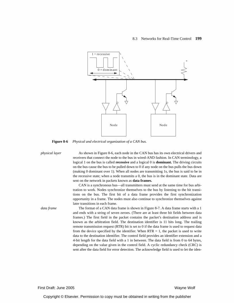
8.3 Networks for Real-Time Control 199
physical layer As shown in Figure 8-6, each node in the CAN bus has its own electrical drivers andreceivers that connect the node to the bus in wired-AND fashion. In CAN terminology, alogical 1 on the bus is called recessive and a logical 0 is dominant. The driving circuitson the bus cause the bus to be pulled down to 0 if any node on the bus pulls the bus down(making 0 dominant over 1). When all nodes are transmitting 1s, the bus is said to be inthe recessive state; when a node transmits a 0, the bus is in the dominant state. Data aresent on the network in packets known as data frames.
CAN is a synchronous bus—all transmitters must send at the same time for bus arbi-tration to work. Nodes synchronize themselves to the bus by listening to the bit transi-tions on the bus. The first bit of a data frame provides the first synchronizationopportunity in a frame. The nodes must also continue to synchronize themselves againstlater transitions in each frame.
data frame The format of a CAN data frame is shown in Figure 8-7. A data frame starts with a 1and ends with a string of seven zeroes. (There are at least three bit fields between dataframes.) The first field in the packet contains the packet’s destination address and isknown as the arbitration field. The destination identifier is 11 bits long. The trailingremote transmission request (RTR) bit is set to 0 if the data frame is used to request datafrom the device specified by the identifier. When RTR = 1, the packet is used to writedata to the destination identifier. The control field provides an identifier extension and a4-bit length for the data field with a 1 in between. The data field is from 0 to 64 bytes,depending on the value given in the control field. A cyclic redundancy check (CRC) issent after the data field for error detection. The acknowledge field is used to let the iden-
Figure 8-6 Physical and electrical organization of a CAN bus.
Node Node
1 = recessive
+
0 = dominant
First Draft: June 2005 Wayne Wolf
Copyright © Elsevier. Permission to copy must be obtained in writing from the publisher
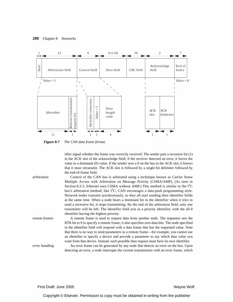
200 Chapter 8 Networks
tifier signal whether the frame was correctly received: The sender puts a recessive bit (1)in the ACK slot of the acknowledge field; if the receiver detected an error, it forces thevalue to a dominant (0) value. If the sender sees a 0 on the bus in the ACK slot, it knowsthat it must retransmit. The ACK slot is followed by a single bit delimiter followed bythe end-of-frame field.
arbitration Control of the CAN bus is arbitrated using a technique known as Carrier SenseMultiple Access with Arbitration on Message Priority (CSMA/AMP). (As seen inSection 8.3.3, Ethernet uses CSMA without AMP.) This method is similar to the I2Cbus’s arbitration method; like I2C, CAN encourages a data-push programming style.Network nodes transmit synchronously, so they all start sending their identifier fieldsat the same time. When a node hears a dominant bit in the identifier when it tries tosend a recessive bit, it stops transmitting. By the end of the arbitration field, only onetransmitter will be left. The identifier field acts as a priority identifier, with the all-0identifier having the highest priority.
remote frames A remote frame is used to request data from another node. The requestor sets theRTR bit to 0 to specify a remote frame; it also specifies zero data bits. The node specifiedin the identifier field will respond with a data frame that has the requested value. Notethat there is no way to send parameters in a remote frame—for example, you cannot usean identifier to specify a device and provide a parameter to say which data value youwant from that device. Instead, each possible data request must have its own identifier.
error handling An error frame can be generated by any node that detects an error on the bus. Upondetecting an error, a node interrupts the current transmission with an error frame, which
Star
t
Arbitration field Control field Data field CRC fieldAcknowledgefield
End offrame
IdentifierDatalengthcode
Rem
ote
tran
smis
sio
n
req
ues
t bit
Iden
tifi
er e
xten
sio
n
Val
ue
= 1
ACKdelimiter
ACKslot
Value = 1 Value = 0
1 12 6 0 to 64 16 2 7
1 11111 1 4
Figure 8-7 The CAN data frame format.
First Draft: June 2005 Wayne Wolf
Copyright © Elsevier. Permission to copy must be obtained in writing from the publisher
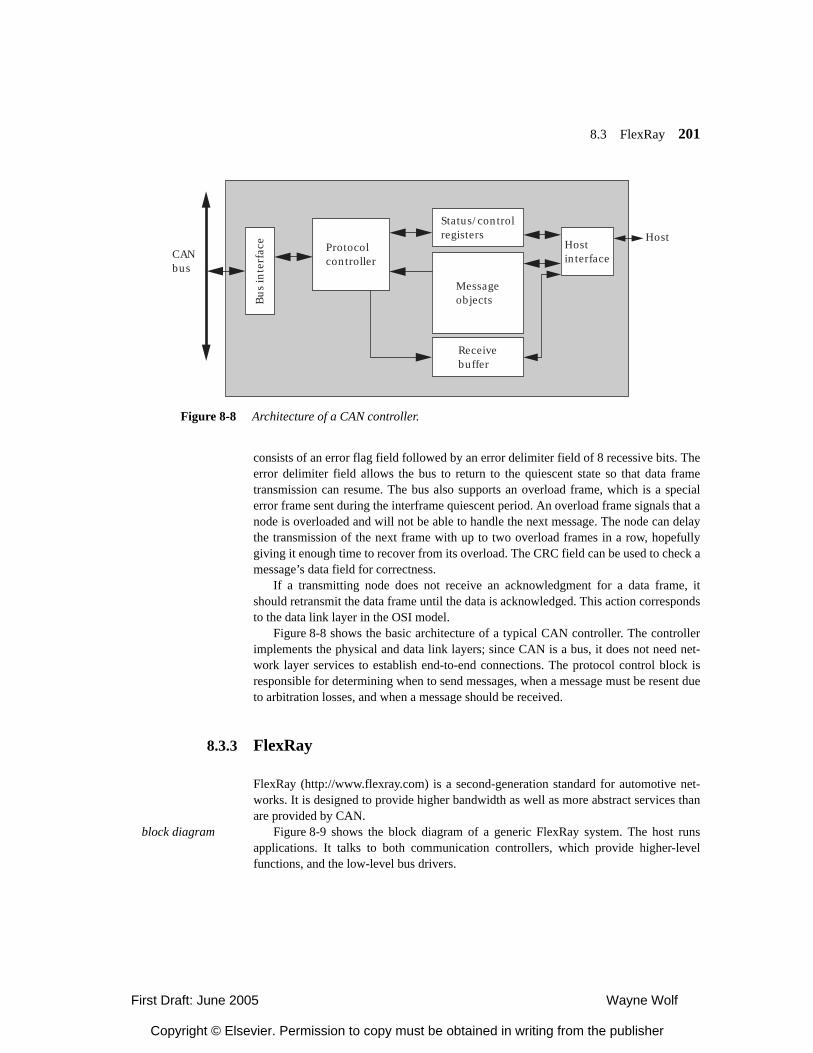
8.3 FlexRay 201
consists of an error flag field followed by an error delimiter field of 8 recessive bits. Theerror delimiter field allows the bus to return to the quiescent state so that data frametransmission can resume. The bus also supports an overload frame, which is a specialerror frame sent during the interframe quiescent period. An overload frame signals that anode is overloaded and will not be able to handle the next message. The node can delaythe transmission of the next frame with up to two overload frames in a row, hopefullygiving it enough time to recover from its overload. The CRC field can be used to check amessage’s data field for correctness.
If a transmitting node does not receive an acknowledgment for a data frame, itshould retransmit the data frame until the data is acknowledged. This action correspondsto the data link layer in the OSI model.
Figure 8-8 shows the basic architecture of a typical CAN controller. The controllerimplements the physical and data link layers; since CAN is a bus, it does not need net-work layer services to establish end-to-end connections. The protocol control block isresponsible for determining when to send messages, when a message must be resent dueto arbitration losses, and when a message should be received.
8.3.3 FlexRay
FlexRay (http://www.flexray.com) is a second-generation standard for automotive net-works. It is designed to provide higher bandwidth as well as more abstract services thanare provided by CAN.
block diagram Figure 8-9 shows the block diagram of a generic FlexRay system. The host runsapplications. It talks to both communication controllers, which provide higher-levelfunctions, and the low-level bus drivers.
Status/controlregisters
Receivebuffer
MessageobjectsB
us
inte
rfac
eProtocolcontroller
HostinterfaceCAN
bus
Host
Figure 8-8 Architecture of a CAN controller.
First Draft: June 2005 Wayne Wolf
Copyright © Elsevier. Permission to copy must be obtained in writing from the publisher
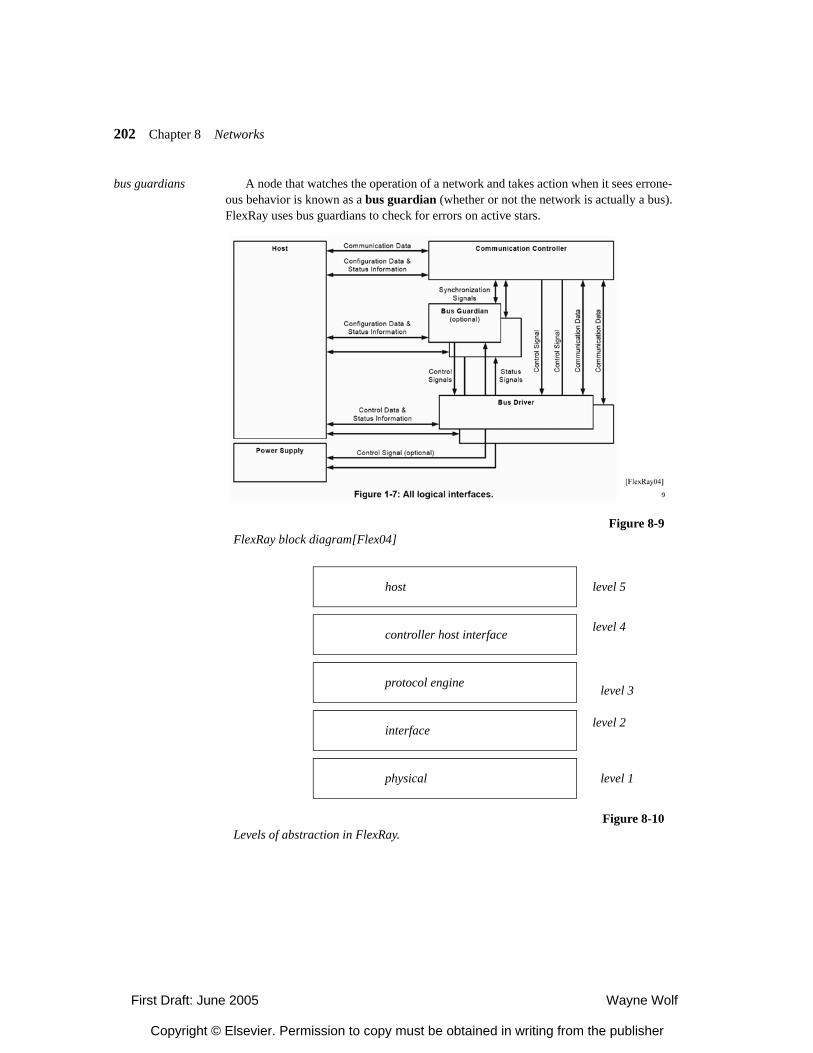
202 Chapter 8 Networks
bus guardians A node that watches the operation of a network and takes action when it sees errone-ous behavior is known as a bus guardian (whether or not the network is actually a bus).FlexRay uses bus guardians to check for errors on active stars.
Figure 8-9FlexRay block diagram[Flex04]
Figure 8-10Levels of abstraction in FlexRay.
physical
interface
protocol engine
controller host interface
host
level 1
level 2
level 3
level 4
level 5
First Draft: June 2005 Wayne Wolf
Copyright © Elsevier. Permission to copy must be obtained in writing from the publisher
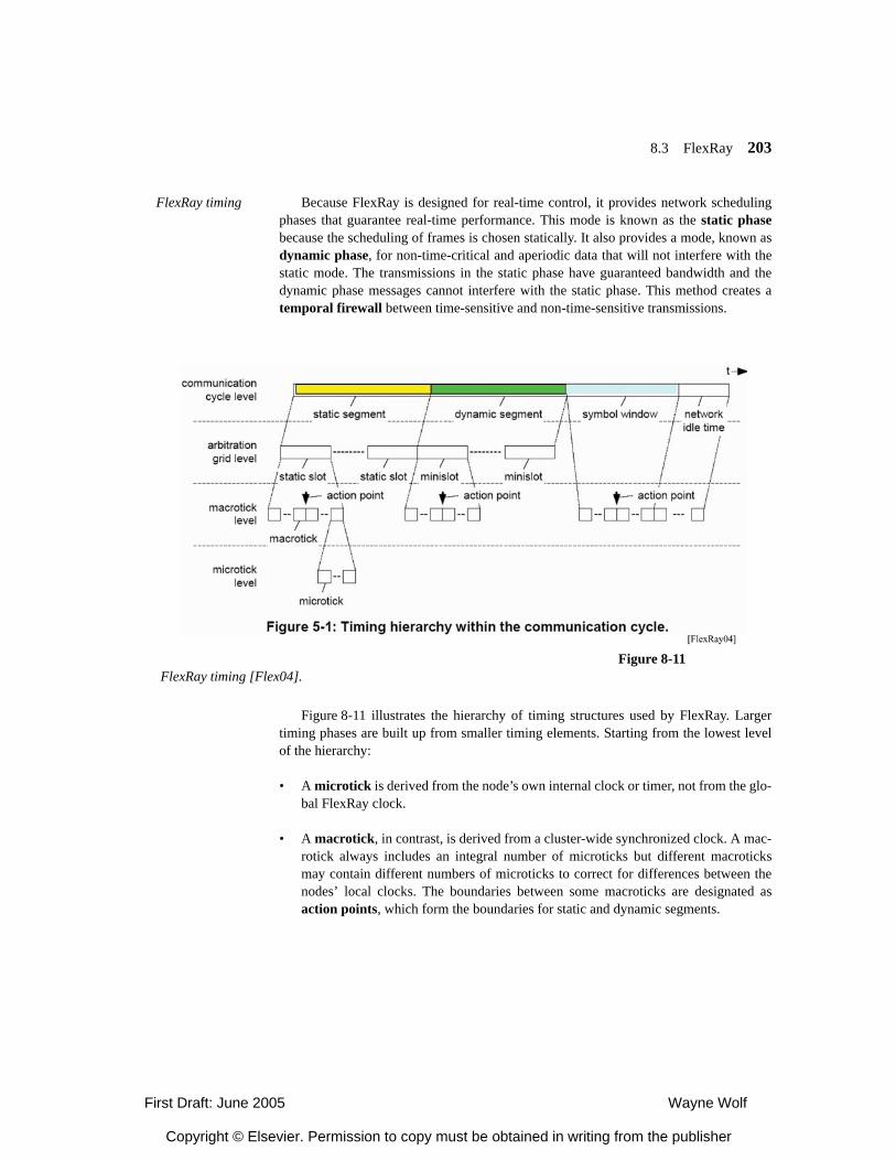
8.3 FlexRay 203
FlexRay timing Because FlexRay is designed for real-time control, it provides network schedulingphases that guarantee real-time performance. This mode is known as the static phasebecause the scheduling of frames is chosen statically. It also provides a mode, known asdynamic phase, for non-time-critical and aperiodic data that will not interfere with thestatic mode. The transmissions in the static phase have guaranteed bandwidth and thedynamic phase messages cannot interfere with the static phase. This method creates atemporal firewall between time-sensitive and non-time-sensitive transmissions.
Figure 8-11 illustrates the hierarchy of timing structures used by FlexRay. Largertiming phases are built up from smaller timing elements. Starting from the lowest levelof the hierarchy:
• A microtick is derived from the node’s own internal clock or timer, not from the glo-bal FlexRay clock.
• A macrotick, in contrast, is derived from a cluster-wide synchronized clock. A mac-rotick always includes an integral number of microticks but different macroticksmay contain different numbers of microticks to correct for differences between thenodes’ local clocks. The boundaries between some macroticks are designated asaction points, which form the boundaries for static and dynamic segments.
Figure 8-11FlexRay timing [Flex04].
First Draft: June 2005 Wayne Wolf
Copyright © Elsevier. Permission to copy must be obtained in writing from the publisher
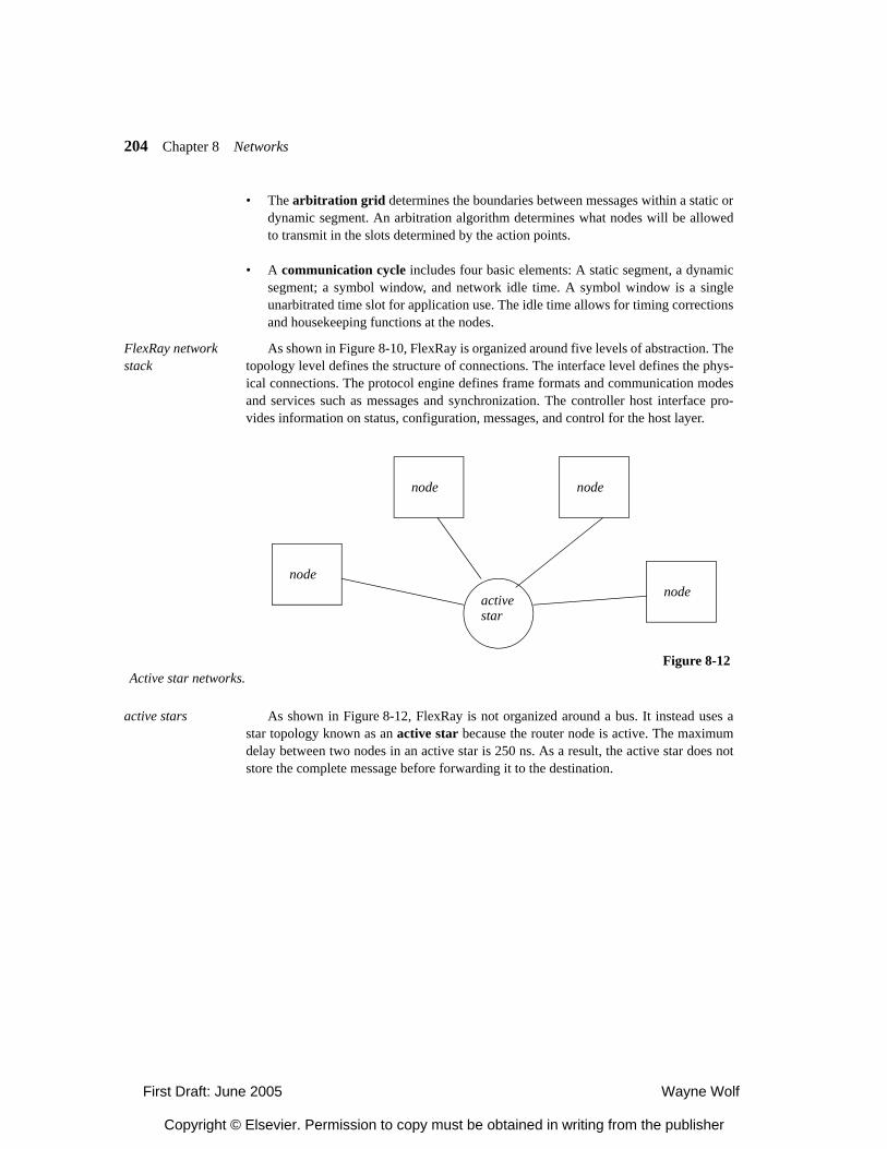
204 Chapter 8 Networks
• The arbitration grid determines the boundaries between messages within a static ordynamic segment. An arbitration algorithm determines what nodes will be allowedto transmit in the slots determined by the action points.
• A communication cycle includes four basic elements: A static segment, a dynamicsegment; a symbol window, and network idle time. A symbol window is a singleunarbitrated time slot for application use. The idle time allows for timing correctionsand housekeeping functions at the nodes.
FlexRay network stack
As shown in Figure 8-10, FlexRay is organized around five levels of abstraction. Thetopology level defines the structure of connections. The interface level defines the phys-ical connections. The protocol engine defines frame formats and communication modesand services such as messages and synchronization. The controller host interface pro-vides information on status, configuration, messages, and control for the host layer.
active stars As shown in Figure 8-12, FlexRay is not organized around a bus. It instead uses astar topology known as an active star because the router node is active. The maximumdelay between two nodes in an active star is 250 ns. As a result, the active star does notstore the complete message before forwarding it to the destination.
Figure 8-12Active star networks.
node
node node
nodeactivestar
First Draft: June 2005 Wayne Wolf
Copyright © Elsevier. Permission to copy must be obtained in writing from the publisher
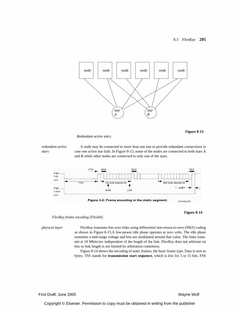
8.3 FlexRay 205
redundant active stars
A node may be connected to more than one star to provide redundant connections incase one active star fails. In Figure 8-13, some of the nodes are connected to both stars Aand B while other nodes are connected to only one of the stars.
physical layer FlexRay transmits bits over links using differential non-return-to-zero (NRZ) codingas shown in Figure 8-15.A low-power idle phase operates at zero volts. The idle phasetransmits a mid-range voltage and bits are modulated around that value. The links trans-mit at 10 Mbits/sec independent of the length of the link. FlexRay does not arbitrate onbits so link length is not limited by arbitration contention.
Figure 8-14 shows the encoding of static frames, the basic frame type. Data is sent asbytes. TSS stands for transmission start sequence, which is low for 5 to 15 bits. FSS
Figure 8-13Redundant active stars.
node node node node node node
starA
starB
Figure 8-14FlexRay frame encoding [Flex04].
First Draft: June 2005 Wayne Wolf
Copyright © Elsevier. Permission to copy must be obtained in writing from the publisher
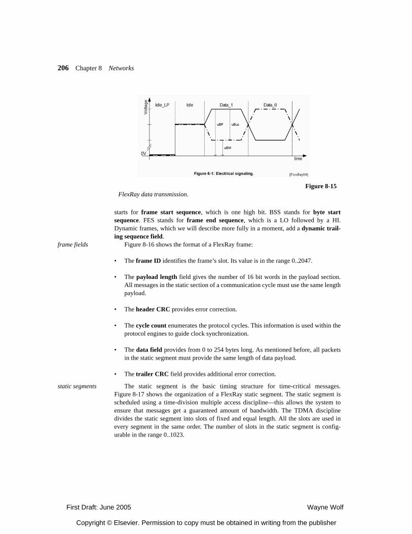
206 Chapter 8 Networks
starts for frame start sequence, which is one high bit. BSS stands for byte startsequence. FES stands for frame end sequence, which is a LO followed by a HI.Dynamic frames, which we will describe more fully in a moment, add a dynamic trail-ing sequence field.
frame fields Figure 8-16 shows the format of a FlexRay frame:
• The frame ID identifies the frame’s slot. Its value is in the range 0..2047.
• The payload length field gives the number of 16 bit words in the payload section.All messages in the static section of a communication cycle must use the same lengthpayload.
• The header CRC provides error correction.
• The cycle count enumerates the protocol cycles. This information is used within theprotocol engines to guide clock synchronization.
• The data field provides from 0 to 254 bytes long. As mentioned before, all packetsin the static segment must provide the same length of data payload.
• The trailer CRC field provides additional error correction.
static segments The static segment is the basic timing structure for time-critical messages.Figure 8-17 shows the organization of a FlexRay static segment. The static segment isscheduled using a time-division multiple access discipline—this allows the system toensure that messages get a guaranteed amount of bandwidth. The TDMA disciplinedivides the static segment into slots of fixed and equal length. All the slots are used inevery segment in the same order. The number of slots in the static segment is config-urable in the range 0..1023.
Figure 8-15FlexRay data transmission.
First Draft: June 2005 Wayne Wolf
Copyright © Elsevier. Permission to copy must be obtained in writing from the publisher
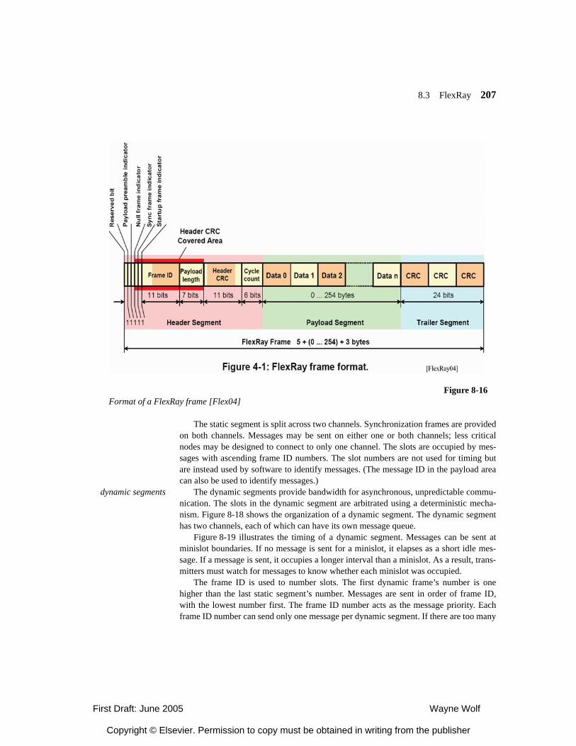
8.3 FlexRay 207
The static segment is split across two channels. Synchronization frames are providedon both channels. Messages may be sent on either one or both channels; less criticalnodes may be designed to connect to only one channel. The slots are occupied by mes-sages with ascending frame ID numbers. The slot numbers are not used for timing butare instead used by software to identify messages. (The message ID in the payload areacan also be used to identify messages.)
dynamic segments The dynamic segments provide bandwidth for asynchronous, unpredictable commu-nication. The slots in the dynamic segment are arbitrated using a deterministic mecha-nism. Figure 8-18 shows the organization of a dynamic segment. The dynamic segmenthas two channels, each of which can have its own message queue.
Figure 8-19 illustrates the timing of a dynamic segment. Messages can be sent atminislot boundaries. If no message is sent for a minislot, it elapses as a short idle mes-sage. If a message is sent, it occupies a longer interval than a minislot. As a result, trans-mitters must watch for messages to know whether each minislot was occupied.
The frame ID is used to number slots. The first dynamic frame’s number is onehigher than the last static segment’s number. Messages are sent in order of frame ID,with the lowest number first. The frame ID number acts as the message priority. Eachframe ID number can send only one message per dynamic segment. If there are too many
Figure 8-16Format of a FlexRay frame [Flex04]
First Draft: June 2005 Wayne Wolf
Copyright © Elsevier. Permission to copy must be obtained in writing from the publisher
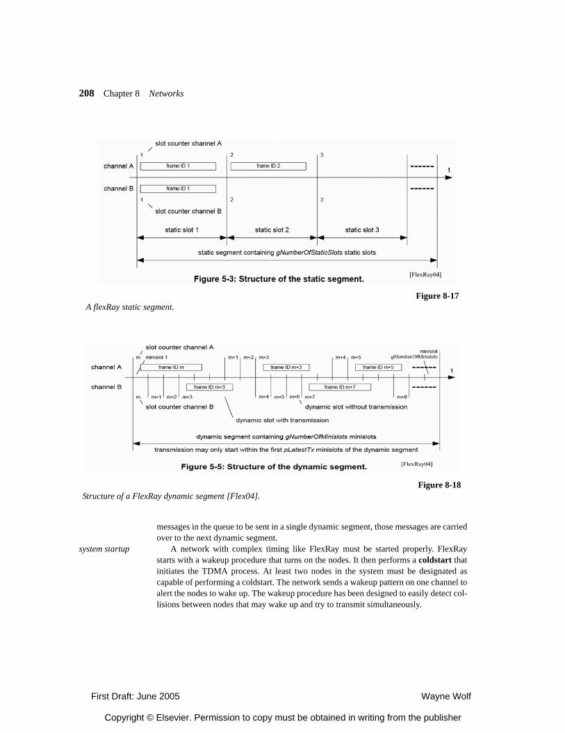
208 Chapter 8 Networks
messages in the queue to be sent in a single dynamic segment, those messages are carriedover to the next dynamic segment.
system startup A network with complex timing like FlexRay must be started properly. FlexRaystarts with a wakeup procedure that turns on the nodes. It then performs a coldstart thatinitiates the TDMA process. At least two nodes in the system must be designated ascapable of performing a coldstart. The network sends a wakeup pattern on one channel toalert the nodes to wake up. The wakeup procedure has been designed to easily detect col-lisions between nodes that may wake up and try to transmit simultaneously.
Figure 8-17A flexRay static segment.
Figure 8-18Structure of a FlexRay dynamic segment [Flex04].
First Draft: June 2005 Wayne Wolf
Copyright © Elsevier. Permission to copy must be obtained in writing from the publisher
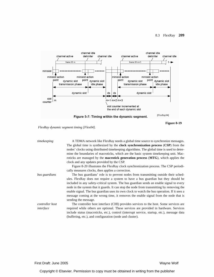
8.3 FlexRay 209
timekeeping A TDMA network like FlexRay needs a global time source to synchronize messages.The global time is synthesized by the clock synchronization process (CSP) from thenodes’ clocks using distributed timekeeping algorithms. The global time is used to deter-mine the boundaries of macroticks, which are the basic system timekeeping unit. Mac-roticks are managed by the macrotick generation process (MTG), which applies theclock and any updates provided by the CSP.
Figure 8-20 illustrates the FlexRay clock synchronization process. The CSP periodi-cally measures clocks, then applies a correction.
bus guardians The bus guardians’ role is to prevent nodes from transmitting outside their sched-ules. FlexRay does not require a system to have a bus guardian but they should beincluded in any safety-critical system. The bus guardian sends an enable signal to everynode in the system that it guards. It can stop the node from transmitting by removing theenable signal. The bus guardian uses its own clock to watch the bus operation. If it sees amessage coming at the wrong time, it removes the enable signal from the node that issending the message.
controller host interface
The controller host interface (CHI) provides services to the host. Some services arerequired while others are optional. These services are provided in hardware. Servicesinclude status (macroticks, etc.), control (interrupt service, startup, etc.), message data(buffering, etc.), and configuration (node and cluster).
Figure 8-19FlexRay dynamic segment timing [Flex04].
First Draft: June 2005 Wayne Wolf
Copyright © Elsevier. Permission to copy must be obtained in writing from the publisher
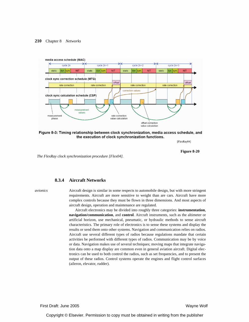
210 Chapter 8 Networks
8.3.4 Aircraft Networks
avionics Aircraft design is similar in some respects to automobile design, but with more stringentrequirements. Aircraft are more sensitive to weight than are cars. Aircraft have morecomplex controls because they must be flown in three dimensions. And most aspects ofaircraft design, operation and maintenance are regulated.
Aircraft electronics may be divided into roughly three categories: instrumentation,navigation/communication, and control. Aircraft instruments, such as the altimeter orartificial horizon, use mechanical, pneumatic, or hydraulic methods to sense aircraftcharacteristics. The primary role of electronics is to sense these systems and display theresults or send them onto other systems. Navigation and communication relies on radios.Aircraft use several different types of radios because regulations mandate that certainactivities be performed with different types of radios. Communication may be by voiceor data. Navigation makes use of several techniques; moving maps that integrate naviga-tion data onto a map display are common even in general aviation aircraft. Digital elec-tronics can be used to both control the radios, such as set frequencies, and to present theoutput of these radios. Control systems operate the engines and flight control surfaces(aileron, elevator, rudder).
Figure 8-20The FlexRay clock synchronization procedure [Flex04].
First Draft: June 2005 Wayne Wolf
Copyright © Elsevier. Permission to copy must be obtained in writing from the publisher
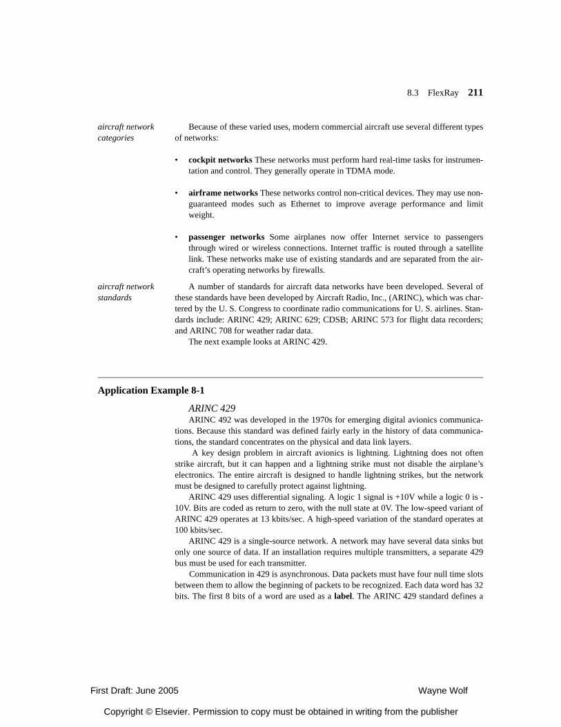
8.3 FlexRay 211
aircraft network categories
Because of these varied uses, modern commercial aircraft use several different typesof networks:
• cockpit networks These networks must perform hard real-time tasks for instrumen-tation and control. They generally operate in TDMA mode.
• airframe networks These networks control non-critical devices. They may use non-guaranteed modes such as Ethernet to improve average performance and limitweight.
• passenger networks Some airplanes now offer Internet service to passengersthrough wired or wireless connections. Internet traffic is routed through a satellitelink. These networks make use of existing standards and are separated from the air-craft’s operating networks by firewalls.
aircraft network standards
A number of standards for aircraft data networks have been developed. Several ofthese standards have been developed by Aircraft Radio, Inc., (ARINC), which was char-tered by the U. S. Congress to coordinate radio communications for U. S. airlines. Stan-dards include: ARINC 429; ARINC 629; CDSB; ARINC 573 for flight data recorders;and ARINC 708 for weather radar data.
The next example looks at ARINC 429.
Application Example 8-1
ARINC 429ARINC 492 was developed in the 1970s for emerging digital avionics communica-
tions. Because this standard was defined fairly early in the history of data communica-tions, the standard concentrates on the physical and data link layers.
A key design problem in aircraft avionics is lightning. Lightning does not oftenstrike aircraft, but it can happen and a lightning strike must not disable the airplane’selectronics. The entire aircraft is designed to handle lightning strikes, but the networkmust be designed to carefully protect against lightning.
ARINC 429 uses differential signaling. A logic 1 signal is +10V while a logic 0 is -10V. Bits are coded as return to zero, with the null state at 0V. The low-speed variant ofARINC 429 operates at 13 kbits/sec. A high-speed variation of the standard operates at100 kbits/sec.
ARINC 429 is a single-source network. A network may have several data sinks butonly one source of data. If an installation requires multiple transmitters, a separate 429bus must be used for each transmitter.
Communication in 429 is asynchronous. Data packets must have four null time slotsbetween them to allow the beginning of packets to be recognized. Each data word has 32bits. The first 8 bits of a word are used as a label. The ARINC 429 standard defines a
First Draft: June 2005 Wayne Wolf
Copyright © Elsevier. Permission to copy must be obtained in writing from the publisher
212 Chapter 8 Networks
number of labels for various uses, such as frequency, heading, acknowledgment, etc. Theword has a 18 bit data payload.
8.3.5 Consumer NetworksConsumer electronics devices may be connected into networks to make them easier
to use and to provide access to audio and video data across the home. This section willlook at some networks used in consumer devices, then consider the challenges of inte-grating networks into consumer devices.
8.4.1 Bluetooth
personal area networks
Bluetooth is a personal area network—designed to connect devices in close prox-imity to a person. The Bluetooth radio operates in the 2.5 GHz spectrum. Its wirelesslinks typically operate within 2 meters, although advanced antennas can extend thatrange to 30 meters. A Bluetooth network can have one master and up to 7 active slaves;more slaves can be parked for a total of 255. Although its low-level communicationmechanisms do require master-slave synchronization, the higher levels of Bluetooth pro-tocols generally operate as a peer-to-peer network, without masters or slaves.
transport group protocols
Figure 8-21 shows the transport group protocols, which belong to layers 1 and 2 ofthe OSI model:
• The physical layer provides basic radio functions.
• The baseband layer defines master/slave relationships and frequency hopping.
8.4
Figure 8-21Bluetooth transport protocols.
physical
baseband
link manager
logical link control and adaptation (L2CAP)
First Draft: June 2005 Wayne Wolf
Copyright © Elsevier. Permission to copy must be obtained in writing from the publisher
8.4 FlexRay 213
• The link manager provides mechanisms for negotiating link properties such asbandwidth and quality-of-service.
• The logical link control and adaptation protocol (L2CAP) hides baseband layeroperations like frequency hopping.
physical layer The Bluetooth radio transmits using frequency-hopping spread spectrum, whichallows several radios to operate in the same frequency band without interference. Theband is divided into 79 1 MHz-wide channels; the Bluetooth radio hops between thesefrequencies at a rate of 1,600 hops/per second. The radio’s transmission power may alsobe controlled.
baseband layer The baseband layer chooses frequency hops according to a pseudo-random sequencethat is agreed upon by the radios; it also controls the radio signal strength to ensure thatthe receiver can properly decode the spread spectrum signal. The baseband layer alsoprovides medium access control, determining packet types and processing. It controlsthe radio power. It provides a real-time clock. It also provides basic security algorithms.
link manager The link manager builds upon the baseband layer to provide several functions. Itschedules transmissions, choosing which data packets to send next. Transmission sched-uling takes quality-of-service contracts into account. It manages overall power consump-tion. The link manager also manages security and encrypts transmissions as specified.
L2CAP layer The L2CAP layer serves as an interface between general-purpose protocols to thelower levels of the Bluetooth stack. It primarily provides asynchronous transmissions. Italso allows higher layers to exchange QoS information.
middleware group protocols
The middleware group protocols provide several widely-used protocols. It pro-vides a serial port abstraction for general-purpose communication. It provides protocolsto interoperate with IrDA infrared networks. It provides a service discovery protocol.And because Bluetooth is widely used for telephone headsets, it provides a telephonycontrol protocol.
RFCOMM The Bluetooth serial interface is known as RFCOMM. It multiplexes several logicalserial communications onto the radio channel. Its signals are compatible with the tradi-tional RS-232 serial standard. It provides several enhancements, including remote statusand configuration, specialized status and configuration and connection establishmentand termination. RFCOMM can emulate a serial port within a single device to provideseamless data service whether the ends of the link are on the same processor or not.
service discovery protocol
The service discovery protocol allows a Bluetooth client device to determinewhether a server device in the network provides a particular service. Services are definedby service records, which consists of a set of <ID,value> attributes. All service recordsinclude a few basic attributes such as class and protocol stack information. A servicemay define its own attributes, such as capabilities. To discover a service, the client asks aserver for a type of service. The server then responds with a service record.
First Draft: June 2005 Wayne Wolf
Copyright © Elsevier. Permission to copy must be obtained in writing from the publisher
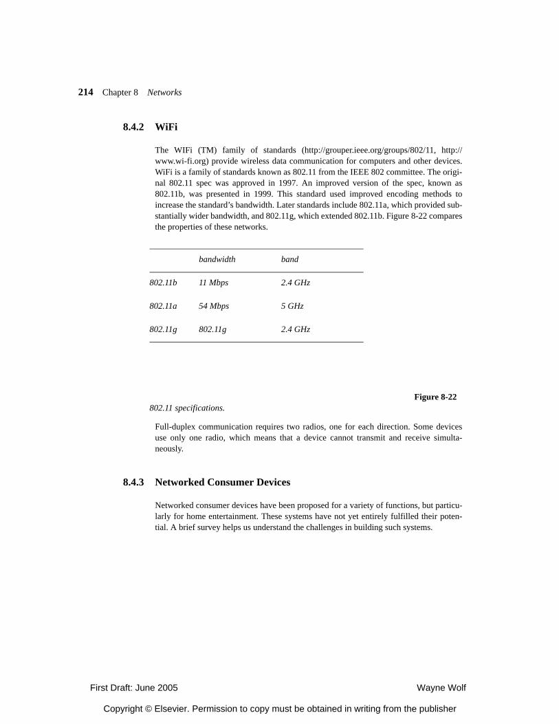
214 Chapter 8 Networks
8.4.2 WiFi
The WIFi (TM) family of standards (http://grouper.ieee.org/groups/802/11, http://www.wi-fi.org) provide wireless data communication for computers and other devices.WiFi is a family of standards known as 802.11 from the IEEE 802 committee. The origi-nal 802.11 spec was approved in 1997. An improved version of the spec, known as802.11b, was presented in 1999. This standard used improved encoding methods toincrease the standard’s bandwidth. Later standards include 802.11a, which provided sub-stantially wider bandwidth, and 802.11g, which extended 802.11b. Figure 8-22 comparesthe properties of these networks.
Full-duplex communication requires two radios, one for each direction. Some devicesuse only one radio, which means that a device cannot transmit and receive simulta-neously.
8.4.3 Networked Consumer Devices
Networked consumer devices have been proposed for a variety of functions, but particu-larly for home entertainment. These systems have not yet entirely fulfilled their poten-tial. A brief survey helps us understand the challenges in building such systems.
Figure 8-22802.11 specifications.
bandwidth band
802.11b 11 Mbps 2.4 GHz
802.11a 54 Mbps 5 GHz
802.11g 802.11g 2.4 GHz
First Draft: June 2005 Wayne Wolf
Copyright © Elsevier. Permission to copy must be obtained in writing from the publisher
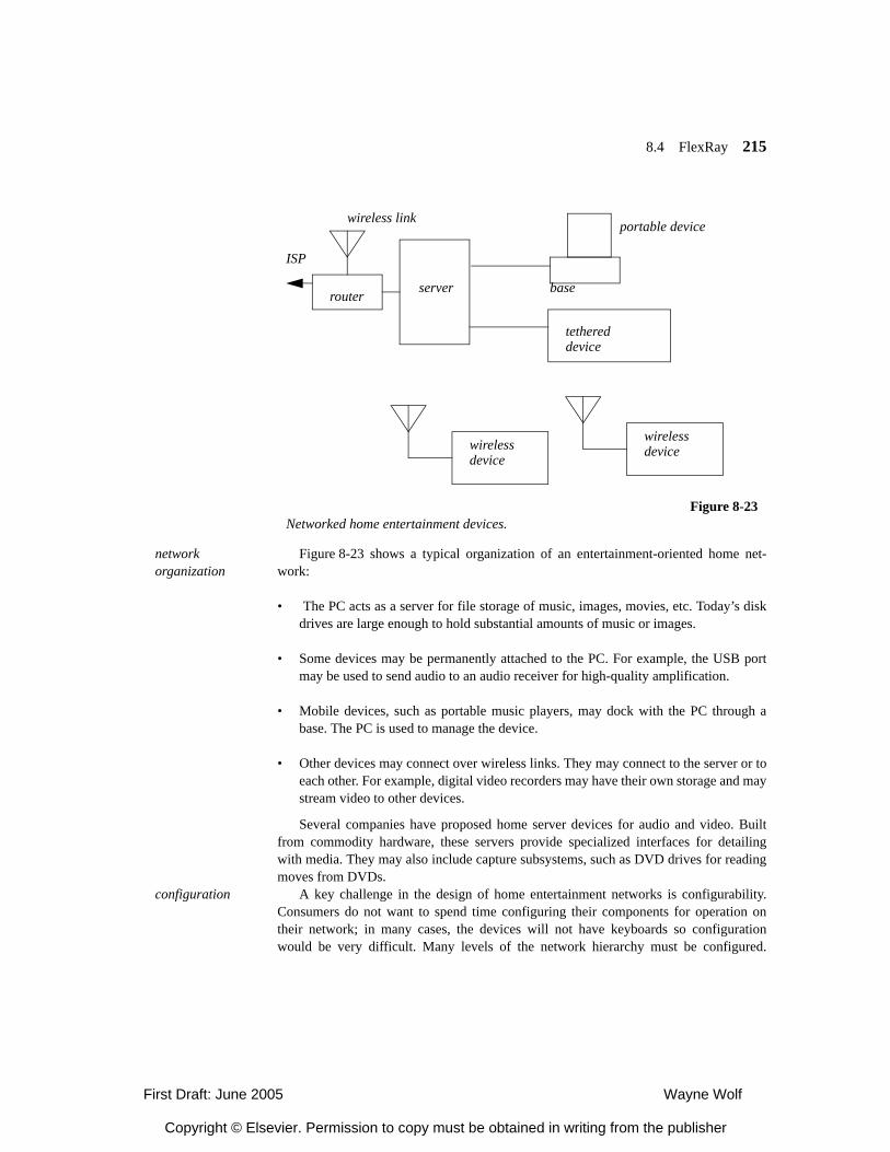
8.4 FlexRay 215
network organization
Figure 8-23 shows a typical organization of an entertainment-oriented home net-work:
• The PC acts as a server for file storage of music, images, movies, etc. Today’s diskdrives are large enough to hold substantial amounts of music or images.
• Some devices may be permanently attached to the PC. For example, the USB portmay be used to send audio to an audio receiver for high-quality amplification.
• Mobile devices, such as portable music players, may dock with the PC through abase. The PC is used to manage the device.
• Other devices may connect over wireless links. They may connect to the server or toeach other. For example, digital video recorders may have their own storage and maystream video to other devices.
Several companies have proposed home server devices for audio and video. Builtfrom commodity hardware, these servers provide specialized interfaces for detailingwith media. They may also include capture subsystems, such as DVD drives for readingmoves from DVDs.
configuration A key challenge in the design of home entertainment networks is configurability.Consumers do not want to spend time configuring their components for operation ontheir network; in many cases, the devices will not have keyboards so configurationwould be very difficult. Many levels of the network hierarchy must be configured.
Figure 8-23Networked home entertainment devices.
server
ISP
base
portable device
router
wireless link
tethereddevice
wirelessdevice
wirelessdevice
First Draft: June 2005 Wayne Wolf
Copyright © Elsevier. Permission to copy must be obtained in writing from the publisher
216 Chapter 8 Networks
Clearly, physical and link-level parameters must be configured. But another importantaspect of configuration is service discovery and configuration. Each device added to thenetwork must be able to determine what other devices it can work with, what services itcan get from other devices, and what services it needs to provide to the rest of the net-work. Service discovery protocols help devices adapt themselves to the network.
software architecture
Java has been used to develop middleware for consumer networks. Java can be effi-ciently executed on a number of different platforms. This not only simplifies softwaredevelopment but also allows devices to trade Java code to provide services.
8.4.4 Sensor Networks
Sensor networks are distributed systems designed to capture and process data. They typ-ically use radio links to transmit data between themselves and to servers. Sensor net-works can be used to monitor buildings, equipment, and people.
ad hoc computing A key aspect of the design of sensor networks is the use of ad hoc networks. Sensornetworks can be deployed in a variety of configurations and nodes may be added orremoved at any time. As a result, both the network and the applications running on thesensor nodes must be designed to dynamically determine their configuration and take thenecessary steps to operate under that network configuration.
For example, when data is transmitted to a server, the nodes do not know in advancethe path that data should take to arrive at the server. The nodes must provide multi-hoprouting services to transmit data from node to node in order to arrive to the network.This problem is challenging because not all nodes are within radio range and it may takenetwork effort and computation to determine the topology of the network.
The next two examples describe a sensor network node and its operating system.
Application Example 8-2
The Intel Mote sensor node
8.5
First Draft: June 2005 Wayne Wolf
Copyright © Elsevier. Permission to copy must be obtained in writing from the publisher
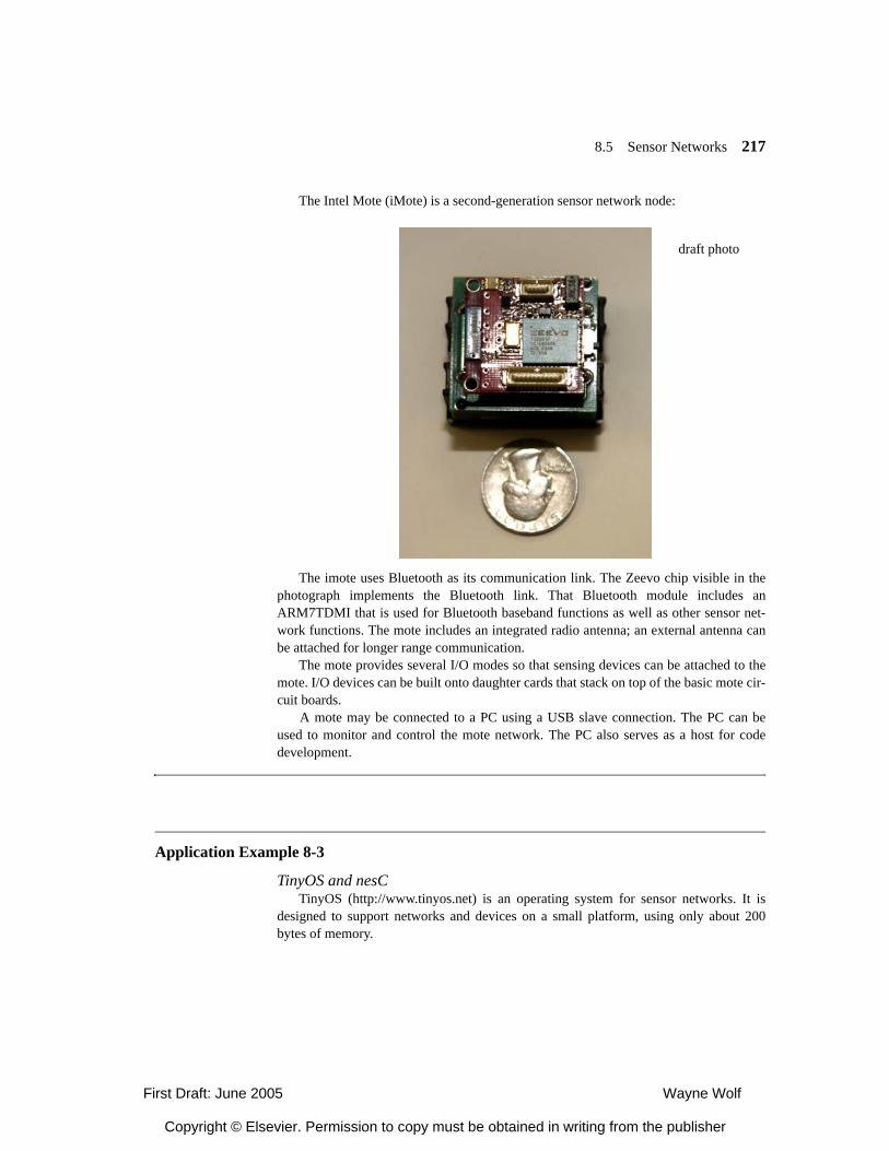
8.5 Sensor Networks 217
The Intel Mote (iMote) is a second-generation sensor network node:
The imote uses Bluetooth as its communication link. The Zeevo chip visible in thephotograph implements the Bluetooth link. That Bluetooth module includes anARM7TDMI that is used for Bluetooth baseband functions as well as other sensor net-work functions. The mote includes an integrated radio antenna; an external antenna canbe attached for longer range communication.
The mote provides several I/O modes so that sensing devices can be attached to themote. I/O devices can be built onto daughter cards that stack on top of the basic mote cir-cuit boards.
A mote may be connected to a PC using a USB slave connection. The PC can beused to monitor and control the mote network. The PC also serves as a host for codedevelopment.
Application Example 8-3
TinyOS and nesCTinyOS (http://www.tinyos.net) is an operating system for sensor networks. It is
designed to support networks and devices on a small platform, using only about 200bytes of memory.
draft photo
First Draft: June 2005 Wayne Wolf
Copyright © Elsevier. Permission to copy must be obtained in writing from the publisher
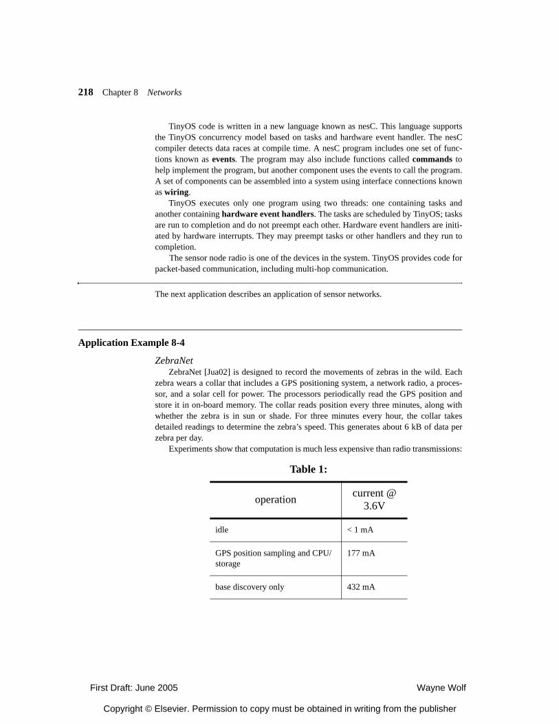
218 Chapter 8 Networks
TinyOS code is written in a new language known as nesC. This language supportsthe TinyOS concurrency model based on tasks and hardware event handler. The nesCcompiler detects data races at compile time. A nesC program includes one set of func-tions known as events. The program may also include functions called commands tohelp implement the program, but another component uses the events to call the program.A set of components can be assembled into a system using interface connections knownas wiring.
TinyOS executes only one program using two threads: one containing tasks andanother containing hardware event handlers. The tasks are scheduled by TinyOS; tasksare run to completion and do not preempt each other. Hardware event handlers are initi-ated by hardware interrupts. They may preempt tasks or other handlers and they run tocompletion.
The sensor node radio is one of the devices in the system. TinyOS provides code forpacket-based communication, including multi-hop communication.
The next application describes an application of sensor networks.
Application Example 8-4
ZebraNetZebraNet [Jua02] is designed to record the movements of zebras in the wild. Each
zebra wears a collar that includes a GPS positioning system, a network radio, a proces-sor, and a solar cell for power. The processors periodically read the GPS position andstore it in on-board memory. The collar reads position every three minutes, along withwhether the zebra is in sun or shade. For three minutes every hour, the collar takesdetailed readings to determine the zebra’s speed. This generates about 6 kB of data perzebra per day.
Experiments show that computation is much less expensive than radio transmissions:
Table 1:
operation current @ 3.6V
idle < 1 mA
GPS position sampling and CPU/storage
177 mA
base discovery only 432 mA
First Draft: June 2005 Wayne Wolf
Copyright © Elsevier. Permission to copy must be obtained in writing from the publisher
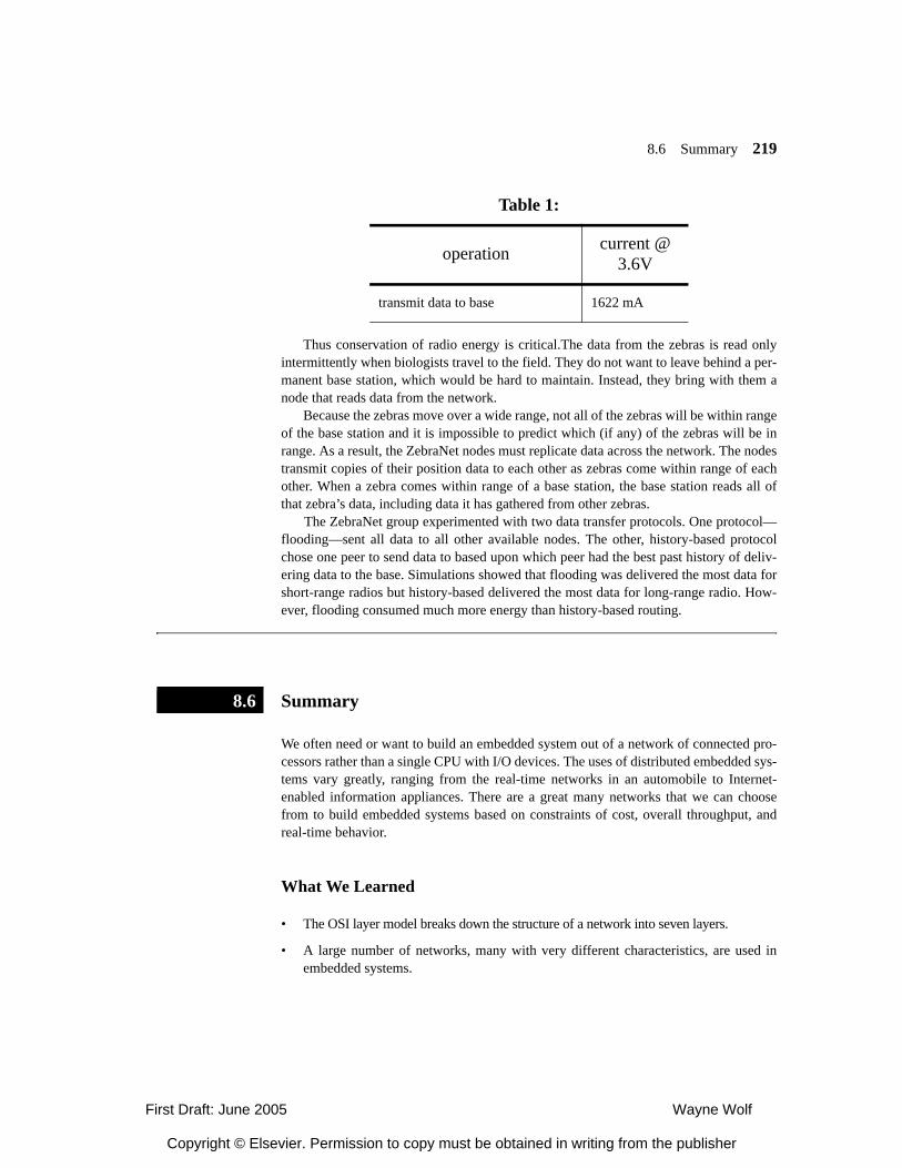
8.6 Summary 219
Thus conservation of radio energy is critical.The data from the zebras is read onlyintermittently when biologists travel to the field. They do not want to leave behind a per-manent base station, which would be hard to maintain. Instead, they bring with them anode that reads data from the network.
Because the zebras move over a wide range, not all of the zebras will be within rangeof the base station and it is impossible to predict which (if any) of the zebras will be inrange. As a result, the ZebraNet nodes must replicate data across the network. The nodestransmit copies of their position data to each other as zebras come within range of eachother. When a zebra comes within range of a base station, the base station reads all ofthat zebra’s data, including data it has gathered from other zebras.
The ZebraNet group experimented with two data transfer protocols. One protocol—flooding—sent all data to all other available nodes. The other, history-based protocolchose one peer to send data to based upon which peer had the best past history of deliv-ering data to the base. Simulations showed that flooding was delivered the most data forshort-range radios but history-based delivered the most data for long-range radio. How-ever, flooding consumed much more energy than history-based routing.
Summary
We often need or want to build an embedded system out of a network of connected pro-cessors rather than a single CPU with I/O devices. The uses of distributed embedded sys-tems vary greatly, ranging from the real-time networks in an automobile to Internet-enabled information appliances. There are a great many networks that we can choosefrom to build embedded systems based on constraints of cost, overall throughput, andreal-time behavior.
What We Learned
• The OSI layer model breaks down the structure of a network into seven layers.
• A large number of networks, many with very different characteristics, are used inembedded systems.
transmit data to base 1622 mA
Table 1:
operation current @ 3.6V
8.6
First Draft: June 2005 Wayne Wolf
Copyright © Elsevier. Permission to copy must be obtained in writing from the publisher
220 Chapter 8 Networks
• Real-time networks use TDMA to guarantee delivery times.
Further Reading
Kopetz [Kop97] provides a thorough introduction to the design of distributed embeddedsystems. Stallings [Sta97A] provides a good introduction to data networking. Helfrick[Hel04] discusses avionics, including aircraft networks. For those interested in the prin-ciples of instrument flight, Dogan [Dog99] provides an excellent introduction.
Questions
Q8-1 Describe a FlexRay bus at the following OSI-compliant levels of detail:a. physical.b. data link.c. network.d. transport.
Q8-2 How do the requirements of aircraft and automobile networks differ? How are they sim-ilar?
Q8-3 How could you use a broadcast network like WiFi for hard real-time control? Whatassumptions would you have to make? What control mechanisms would need to beadded to the network?
Q8-4 Plot computation vs. communication energy in a wireless network.
a. Determine the computation and communication required for a node to receive two16-bit integers and multiply them together.
a. Plot total system energy as a function of computation vs. communication energy.Q8-5 Lab Exercises
L8-1 Build an experimental setup that lets you monitor messages on an embedded network.
L8-2 Measure energy for a single instruction vs. transmission of a single packet for a sensornetwork node.
First Draft: June 2005 Wayne Wolf
Copyright © Elsevier. Permission to copy must be obtained in writing from the publisher
Related Documents