1 SPRAC84 – May 2017 Submit Documentation Feedback Copyright © 2017, Texas Instruments Incorporated Fan Inverter Using PMSM Sensorless FOC Algorithm, Compliant With IEC 60730 (UL1998), Based on TMS320F28021 MCU Application Report SPRAC84 – May 2017 Fan Inverter Using PMSM Sensorless FOC Algorithm, Compliant With IEC 60730 (UL1998), Based on TMS320F28021 MCU Terry Deng ABSTRACT This application note presents a detailed solution to implement in fan motor applications based on TMS320F28021 microcontrollers. The solution uses the PMSM sensorless FOC algorithm, and also designed to comply with the IEC 60730 (UL1998) standard. TMS320F2802x devices are part of the family of C2000 microcontrollers, which enable cost-effective design of intelligent controllers for 3-phase motors by reducing the system components, and also increase efficiency. With these devices it is possible to realize far more precise digital vector control algorithms like the field oriented control (FOC). Implementation of this algorithm is described in this document. The FOC algorithm maintains efficiency in a wide range of speeds, and takes into consideration torque changes with transient phases by processing a dynamic model of the motor. Among the proposed solutions are ways to eliminate the phase current sensors and use an observer for speed sensorless control. Manufacturers of household appliances must take steps to ensure safe and reliable operation of their products to meet the IEC 60730 standard. The IEC 60730 standard covers mechanical, electrical, electronic, EMC, and abnormal operation of AC appliances. Most home appliances including washing machines, dryers, refrigerators, freezers, and cookers or stoves fall into the Class B classification. How to design solutions to fulfill Class B compliance is discussed in this document. Also, the document lists which MCU components must be tested, which faults must be detected, and the appropriate reactive measures.

Welcome message from author
This document is posted to help you gain knowledge. Please leave a comment to let me know what you think about it! Share it to your friends and learn new things together.
Transcript
1SPRAC84–May 2017Submit Documentation Feedback
Copyright © 2017, Texas Instruments Incorporated
Fan Inverter Using PMSM Sensorless FOC Algorithm, Compliant With IEC60730 (UL1998), Based on TMS320F28021 MCU
Application ReportSPRAC84–May 2017
Fan Inverter Using PMSM Sensorless FOC Algorithm,Compliant With IEC 60730 (UL1998), Based on
TMS320F28021 MCU
TerryDeng
ABSTRACTThis application note presents a detailed solution to implement in fan motor applications based onTMS320F28021 microcontrollers. The solution uses the PMSM sensorless FOC algorithm, and alsodesigned to comply with the IEC 60730 (UL1998) standard.
TMS320F2802x devices are part of the family of C2000 microcontrollers, which enable cost-effectivedesign of intelligent controllers for 3-phase motors by reducing the system components, and also increaseefficiency. With these devices it is possible to realize far more precise digital vector control algorithms likethe field oriented control (FOC). Implementation of this algorithm is described in this document. The FOCalgorithm maintains efficiency in a wide range of speeds, and takes into consideration torque changes withtransient phases by processing a dynamic model of the motor. Among the proposed solutions are ways toeliminate the phase current sensors and use an observer for speed sensorless control.
Manufacturers of household appliances must take steps to ensure safe and reliable operation of theirproducts to meet the IEC 60730 standard. The IEC 60730 standard covers mechanical, electrical,electronic, EMC, and abnormal operation of AC appliances. Most home appliances including washingmachines, dryers, refrigerators, freezers, and cookers or stoves fall into the Class B classification. How todesign solutions to fulfill Class B compliance is discussed in this document. Also, the document lists whichMCU components must be tested, which faults must be detected, and the appropriate reactive measures.
www.ti.com
2 SPRAC84–May 2017Submit Documentation Feedback
Copyright © 2017, Texas Instruments Incorporated
Fan Inverter Using PMSM Sensorless FOC Algorithm, Compliant With IEC60730 (UL1998), Based on TMS320F28021 MCU
Contents1 Introduction ................................................................................................................... 32 System Specification ........................................................................................................ 33 MCU Use Overview ......................................................................................................... 44 Hardware Design ............................................................................................................ 55 Firmware Design ............................................................................................................. 86 Fault Handle ................................................................................................................ 117 Microelectronic Fault Protection Function............................................................................... 158 Final Product Performance................................................................................................ 189 Related Documentation.................................................................................................... 20
List of Figures
1 System Overall Structure ................................................................................................... 52 Three-Phase Driver Circuit ................................................................................................. 63 Current Sample Circuit...................................................................................................... 74 Comparator Protection Circuit.............................................................................................. 75 FOC Algorithm Structure.................................................................................................... 86 Main Procedure Flow........................................................................................................ 97 Overcurrent Protection Flow .............................................................................................. 118 Loss Phase Protection Flow .............................................................................................. 129 Lock of Rotor Protection Flow ............................................................................................ 1310 System Config Header File ............................................................................................... 1511 Error Simulation Header File ............................................................................................. 1512 Power Consumption Record ............................................................................................. 1813 60-Hz Current Waveform.................................................................................................. 1914 100-Hz Current Waveform ................................................................................................ 19
List of Tables
1 System Specifications....................................................................................................... 32 MCU Pin Assignment........................................................................................................ 4
TrademarksPiccolo is a trademark of Texas Instruments.All other trademarks are the property of their respective owners.
www.ti.com Introduction
3SPRAC84–May 2017Submit Documentation Feedback
Copyright © 2017, Texas Instruments Incorporated
Fan Inverter Using PMSM Sensorless FOC Algorithm, Compliant With IEC60730 (UL1998), Based on TMS320F28021 MCU
1 IntroductionThis application report presents a fan inverter solution which uses the PMSM sensorless FOC controlalgorithm and complies with the IEC 60730 (UL1998) requirement, based on the TMS320F28021 device.
The goal of the FOC algorithm is to drive the motor magnetic field by generating a sine-wave current, sothat the device can achieve stable output torque, high efficiency, low noise, and vibration. Sensorless FOCtechnology improves motor control system reliability, saves cost, and can be used for any applicationenvironment in which it is difficult to install a sensor.
The fan inverter provides rich functions including a bidirection speed controller, flying start-up, fieldweakening, and power calculation. The fan inverter also provides reliable protection including, OV/UV,OC, loss of phase, lock of rotor, circuit shortage, and power limitation. This solution also complies with theIEC 60730 (UL1998) standard, which is required for international home appliances.
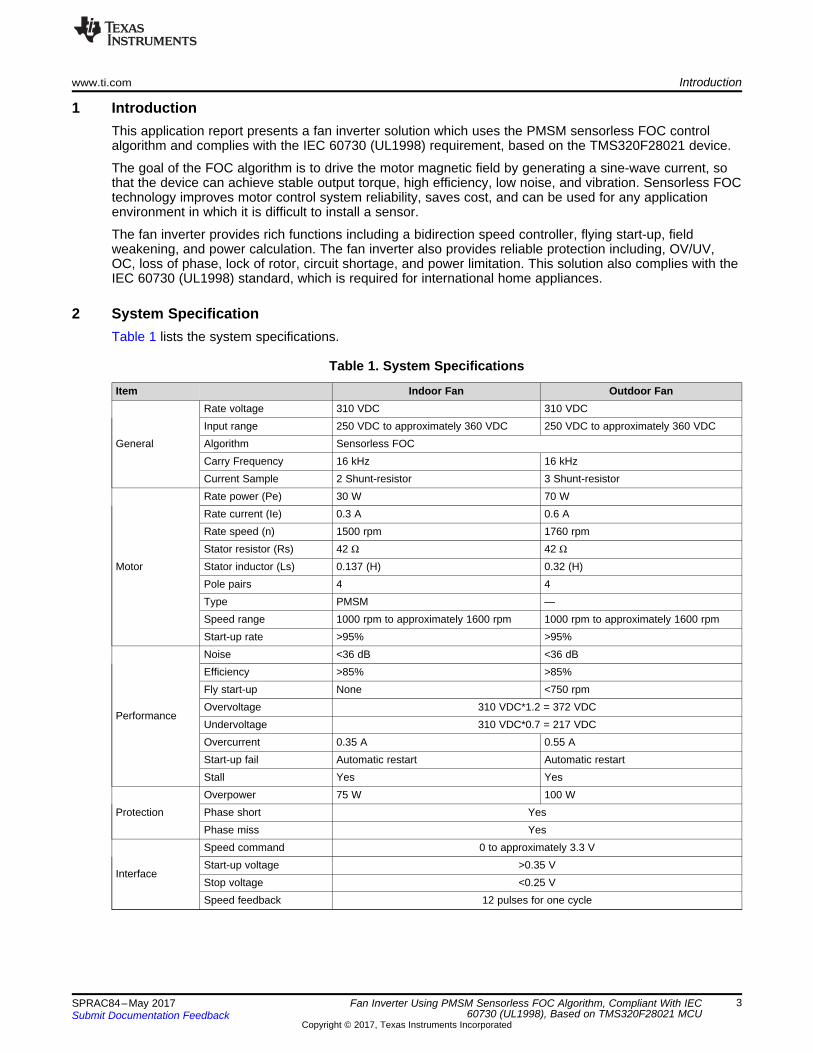
2 System SpecificationTable 1 lists the system specifications.
Table 1. System Specifications
Item Indoor Fan Outdoor Fan
General
Rate voltage 310 VDC 310 VDCInput range 250 VDC to approximately 360 VDC 250 VDC to approximately 360 VDCAlgorithm Sensorless FOCCarry Frequency 16 kHz 16 kHzCurrent Sample 2 Shunt-resistor 3 Shunt-resistor
Motor
Rate power (Pe) 30 W 70 WRate current (Ie) 0.3 A 0.6 ARate speed (n) 1500 rpm 1760 rpmStator resistor (Rs) 42 Ω 42 Ω
Stator inductor (Ls) 0.137 (H) 0.32 (H)Pole pairs 4 4Type PMSM —Speed range 1000 rpm to approximately 1600 rpm 1000 rpm to approximately 1600 rpmStart-up rate >95% >95%
Performance
Noise <36 dB <36 dBEfficiency >85% >85%Fly start-up None <750 rpmOvervoltage 310 VDC*1.2 = 372 VDCUndervoltage 310 VDC*0.7 = 217 VDCOvercurrent 0.35 A 0.55 AStart-up fail Automatic restart Automatic restartStall Yes Yes
ProtectionOverpower 75 W 100 WPhase short YesPhase miss Yes
Interface
Speed command 0 to approximately 3.3 VStart-up voltage >0.35 VStop voltage <0.25 VSpeed feedback 12 pulses for one cycle
MCU Use Overview www.ti.com
4 SPRAC84–May 2017Submit Documentation Feedback
Copyright © 2017, Texas Instruments Incorporated
Fan Inverter Using PMSM Sensorless FOC Algorithm, Compliant With IEC60730 (UL1998), Based on TMS320F28021 MCU
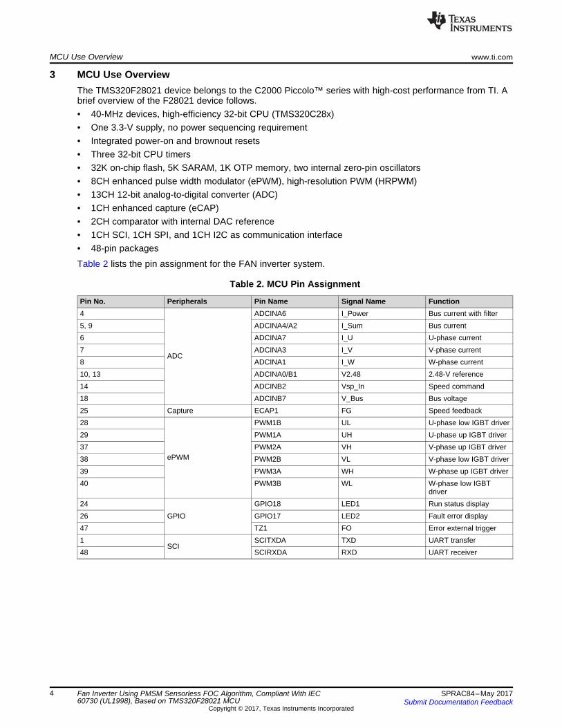
3 MCU Use OverviewThe TMS320F28021 device belongs to the C2000 Piccolo™ series with high-cost performance from TI. Abrief overview of the F28021 device follows.• 40-MHz devices, high-efficiency 32-bit CPU (TMS320C28x)• One 3.3-V supply, no power sequencing requirement• Integrated power-on and brownout resets• Three 32-bit CPU timers• 32K on-chip flash, 5K SARAM, 1K OTP memory, two internal zero-pin oscillators• 8CH enhanced pulse width modulator (ePWM), high-resolution PWM (HRPWM)• 13CH 12-bit analog-to-digital converter (ADC)• 1CH enhanced capture (eCAP)• 2CH comparator with internal DAC reference• 1CH SCI, 1CH SPI, and 1CH I2C as communication interface• 48-pin packages
Table 2 lists the pin assignment for the FAN inverter system.
Table 2. MCU Pin Assignment
Pin No. Peripherals Pin Name Signal Name Function4
ADC
ADCINA6 I_Power Bus current with filter5, 9 ADCINA4/A2 I_Sum Bus current6 ADCINA7 I_U U-phase current7 ADCINA3 I_V V-phase current8 ADCINA1 I_W W-phase current10, 13 ADCINA0/B1 V2.48 2.48-V reference14 ADCINB2 Vsp_In Speed command18 ADCINB7 V_Bus Bus voltage25 Capture ECAP1 FG Speed feedback28
ePWM
PWM1B UL U-phase low IGBT driver29 PWM1A UH U-phase up IGBT driver37 PWM2A VH V-phase up IGBT driver38 PWM2B VL V-phase low IGBT driver39 PWM3A WH W-phase up IGBT driver40 PWM3B WL W-phase low IGBT
driver24
GPIOGPIO18 LED1 Run status display
26 GPIO17 LED2 Fault error display47 TZ1 FO Error external trigger1
SCISCITXDA TXD UART transfer
48 SCIRXDA RXD UART receiver
VoltageSensing
PhaseCurrent
Feedback
3 PhaseMotor
DC-Bus
IPM
Inverter BusVoltage
Feedback
PWM-1A
PWM-1B
PWM-2A
PWM-2B
PWM-3A
PWM-3B
15 V1H
2H
3H
1L
2L
3L
2H 3H
2L 3L
www.ti.com Hardware Design
5SPRAC84–May 2017Submit Documentation Feedback
Copyright © 2017, Texas Instruments Incorporated
Fan Inverter Using PMSM Sensorless FOC Algorithm, Compliant With IEC60730 (UL1998), Based on TMS320F28021 MCU
4 Hardware Design
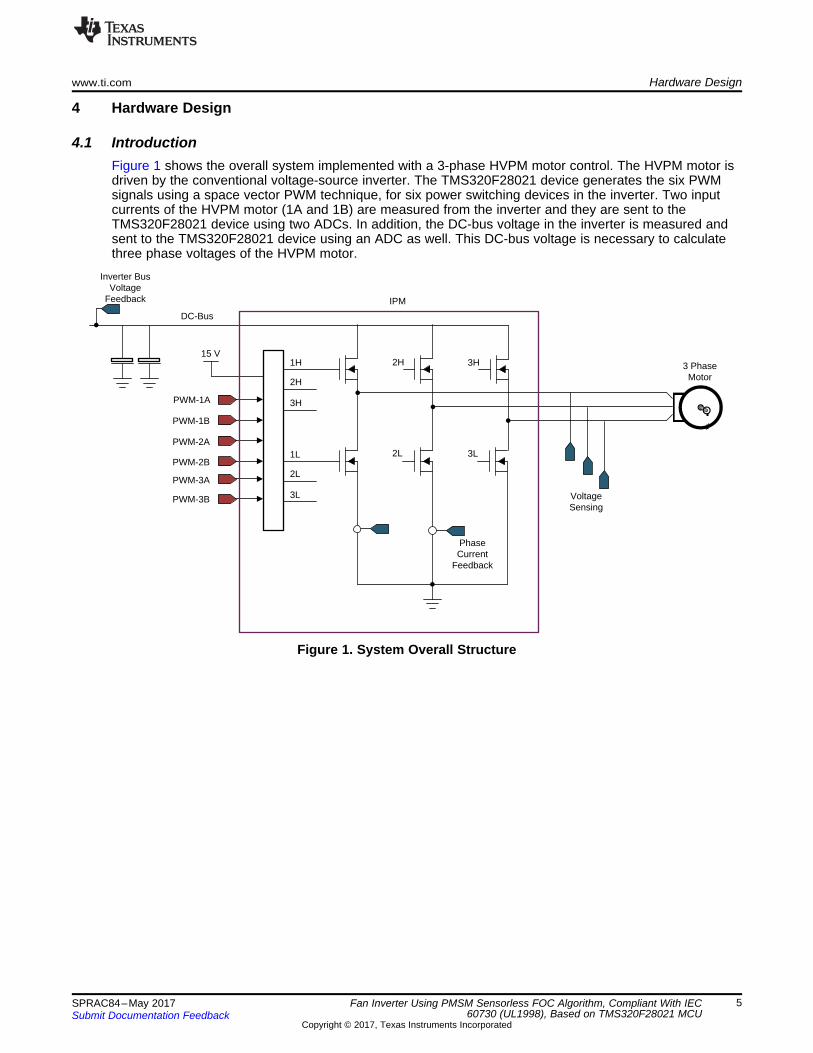
4.1 IntroductionFigure 1 shows the overall system implemented with a 3-phase HVPM motor control. The HVPM motor isdriven by the conventional voltage-source inverter. The TMS320F28021 device generates the six PWMsignals using a space vector PWM technique, for six power switching devices in the inverter. Two inputcurrents of the HVPM motor (1A and 1B) are measured from the inverter and they are sent to theTMS320F28021 device using two ADCs. In addition, the DC-bus voltage in the inverter is measured andsent to the TMS320F28021 device using an ADC as well. This DC-bus voltage is necessary to calculatethree phase voltages of the HVPM motor.
Figure 1. System Overall Structure
Hardware Design www.ti.com
6 SPRAC84–May 2017Submit Documentation Feedback
Copyright © 2017, Texas Instruments Incorporated
Fan Inverter Using PMSM Sensorless FOC Algorithm, Compliant With IEC60730 (UL1998), Based on TMS320F28021 MCU
4.2 Key MCU Peripheral and Circuit Module
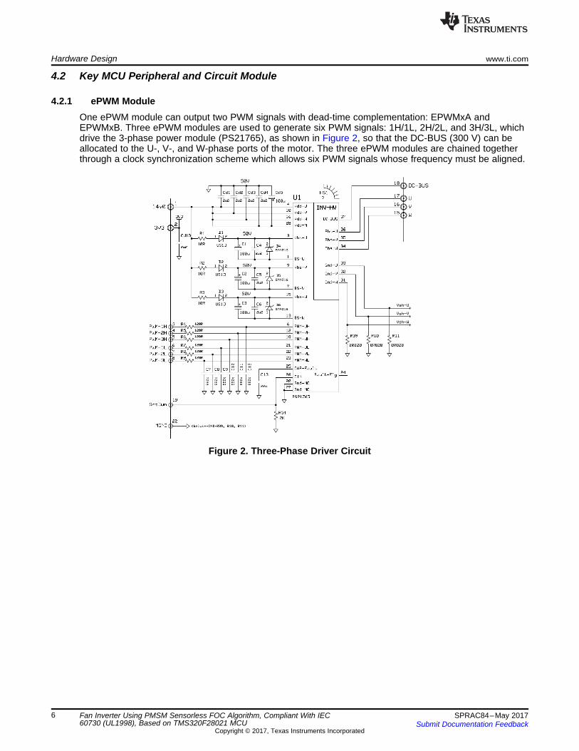
4.2.1 ePWM ModuleOne ePWM module can output two PWM signals with dead-time complementation: EPWMxA andEPWMxB. Three ePWM modules are used to generate six PWM signals: 1H/1L, 2H/2L, and 3H/3L, whichdrive the 3-phase power module (PS21765), as shown in Figure 2, so that the DC-BUS (300 V) can beallocated to the U-, V-, and W-phase ports of the motor. The three ePWM modules are chained togetherthrough a clock synchronization scheme which allows six PWM signals whose frequency must be aligned.
Figure 2. Three-Phase Driver Circuit
www.ti.com Hardware Design
7SPRAC84–May 2017Submit Documentation Feedback
Copyright © 2017, Texas Instruments Incorporated
Fan Inverter Using PMSM Sensorless FOC Algorithm, Compliant With IEC60730 (UL1998), Based on TMS320F28021 MCU
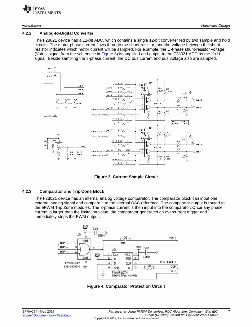
4.2.2 Analog-to-Digital ConverterThe F28021 device has a 12-bit ADC, which contains a single 12-bit converter fed by two sample and holdcircuits. The motor phase current flows through the shunt-resistor, and the voltage between the shunt-resistor indicates which motor current will be sampled. For example, the U-Phase shunt-resistor voltage(Vsh-U signal from the schematic in Figure 3) is amplified and output to the F28021 ADC as the Ifb-Usignal. Beside sampling the 3-phase current, the DC bus current and bus voltage also are sampled.
Figure 3. Current Sample Circuit
4.2.3 Comparator and Trip-Zone BlockThe F28021 device has an internal analog voltage comparator. The comparator block can input oneexternal analog signal and compare it to the internal DAC reference. The comparator output is routed tothe ePWM Trip Zone modules. The 3-phase current is then input into the comparator. Once any phasecurrent is larger than the limitation value, the comparator generates an overcurrent trigger andimmediately stops the PWM output.
Figure 4. Comparator Protection Circuit
PI PI
PI
Inv. Park Trans. Space-
VectorPWM
Generator
ParkTrans.
VoltageSourceInverter
SpeedCalculatorbased onestimated
rotorposition
Sliding-modebasedrotor
positionestimator
Phase voltagereconstruction
ClarkeTrans.
VSdref
VSqref
iSdref+
- iSd
iSqref
+-
iSq iS.�
iS��
VS.ref
VS�ref
VS.�
VS��
iS.�
iS��
�
�
�
DC Bus
PWM1
PWM2
PWM3
PWM4
PWM5
PWM6
iSa
iSb
PMSM
PWM1
PWM3
PWM5
Vdc
+-
Ir
Ir
+
^
Firmware Design www.ti.com
8 SPRAC84–May 2017Submit Documentation Feedback
Copyright © 2017, Texas Instruments Incorporated
Fan Inverter Using PMSM Sensorless FOC Algorithm, Compliant With IEC60730 (UL1998), Based on TMS320F28021 MCU
5 Firmware Design
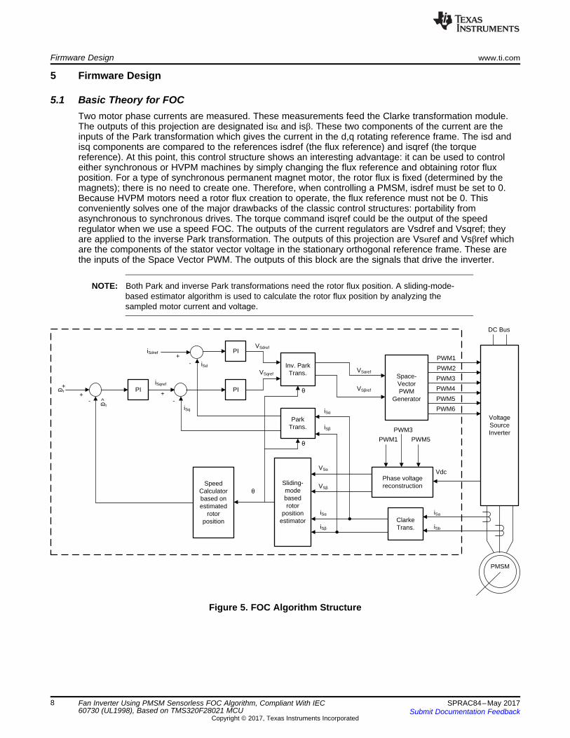
5.1 Basic Theory for FOCTwo motor phase currents are measured. These measurements feed the Clarke transformation module.The outputs of this projection are designated isα and isβ. These two components of the current are theinputs of the Park transformation which gives the current in the d,q rotating reference frame. The isd andisq components are compared to the references isdref (the flux reference) and isqref (the torquereference). At this point, this control structure shows an interesting advantage: it can be used to controleither synchronous or HVPM machines by simply changing the flux reference and obtaining rotor fluxposition. For a type of synchronous permanent magnet motor, the rotor flux is fixed (determined by themagnets); there is no need to create one. Therefore, when controlling a PMSM, isdref must be set to 0.Because HVPM motors need a rotor flux creation to operate, the flux reference must not be 0. Thisconveniently solves one of the major drawbacks of the classic control structures: portability fromasynchronous to synchronous drives. The torque command isqref could be the output of the speedregulator when we use a speed FOC. The outputs of the current regulators are Vsdref and Vsqref; theyare applied to the inverse Park transformation. The outputs of this projection are Vsαref and Vsβref whichare the components of the stator vector voltage in the stationary orthogonal reference frame. These arethe inputs of the Space Vector PWM. The outputs of this block are the signals that drive the inverter.
NOTE: Both Park and inverse Park transformations need the rotor flux position. A sliding-mode-based estimator algorithm is used to calculate the rotor flux position by analyzing thesampled motor current and voltage.
Figure 5. FOC Algorithm Structure
Reset
System Initiation
Power Up Test
System Stop
System Running
Action_Running
Period Test
Action_Testing
Fault Action
Action_Stop
www.ti.com Firmware Design
9SPRAC84–May 2017Submit Documentation Feedback
Copyright © 2017, Texas Instruments Incorporated
Fan Inverter Using PMSM Sensorless FOC Algorithm, Compliant With IEC60730 (UL1998), Based on TMS320F28021 MCU
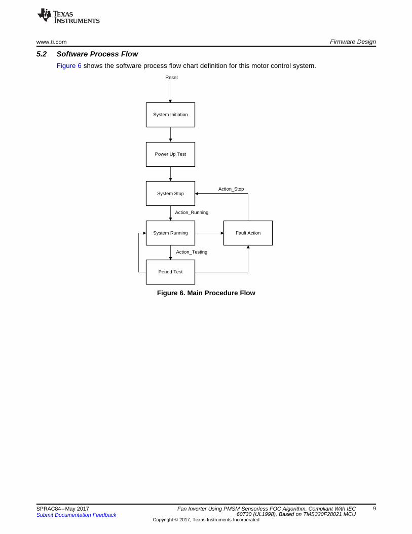
5.2 Software Process FlowFigure 6 shows the software process flow chart definition for this motor control system.
Figure 6. Main Procedure Flow
Firmware Design www.ti.com
10 SPRAC84–May 2017Submit Documentation Feedback
Copyright © 2017, Texas Instruments Incorporated
Fan Inverter Using PMSM Sensorless FOC Algorithm, Compliant With IEC60730 (UL1998), Based on TMS320F28021 MCU
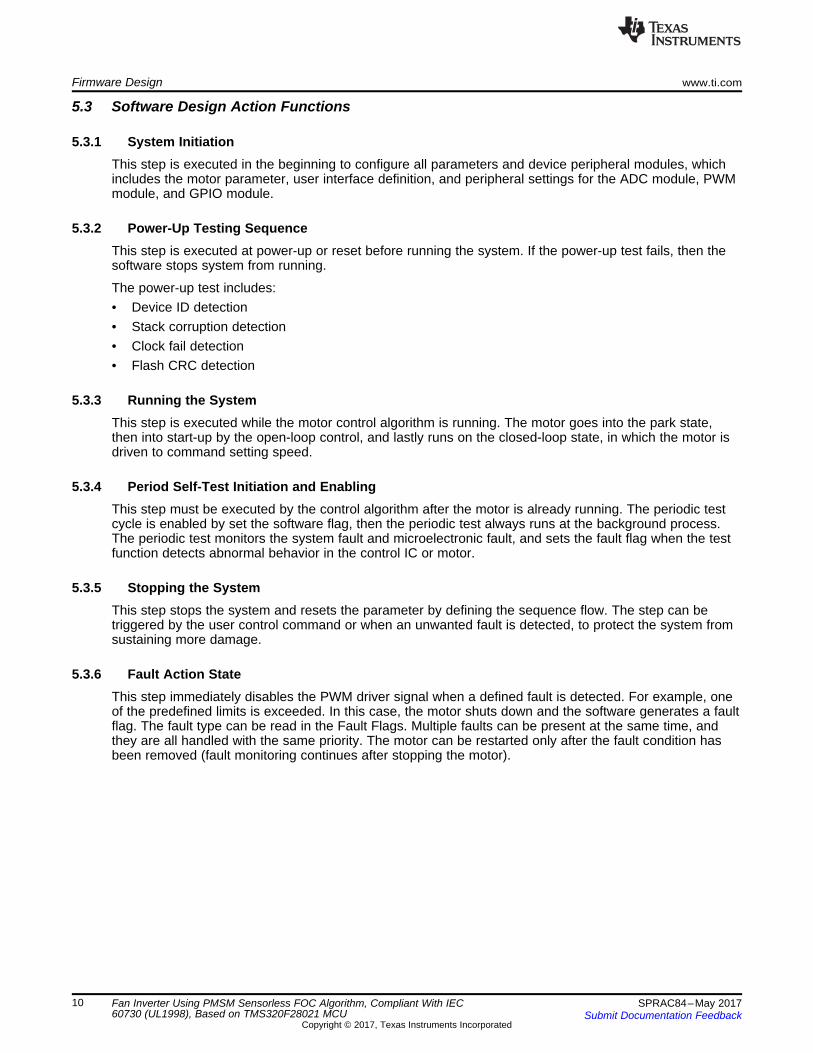
5.3 Software Design Action Functions
5.3.1 System InitiationThis step is executed in the beginning to configure all parameters and device peripheral modules, whichincludes the motor parameter, user interface definition, and peripheral settings for the ADC module, PWMmodule, and GPIO module.
5.3.2 Power-Up Testing SequenceThis step is executed at power-up or reset before running the system. If the power-up test fails, then thesoftware stops system from running.
The power-up test includes:• Device ID detection• Stack corruption detection• Clock fail detection• Flash CRC detection
5.3.3 Running the SystemThis step is executed while the motor control algorithm is running. The motor goes into the park state,then into start-up by the open-loop control, and lastly runs on the closed-loop state, in which the motor isdriven to command setting speed.
5.3.4 Period Self-Test Initiation and EnablingThis step must be executed by the control algorithm after the motor is already running. The periodic testcycle is enabled by set the software flag, then the periodic test always runs at the background process.The periodic test monitors the system fault and microelectronic fault, and sets the fault flag when the testfunction detects abnormal behavior in the control IC or motor.
5.3.5 Stopping the SystemThis step stops the system and resets the parameter by defining the sequence flow. The step can betriggered by the user control command or when an unwanted fault is detected, to protect the system fromsustaining more damage.
5.3.6 Fault Action StateThis step immediately disables the PWM driver signal when a defined fault is detected. For example, oneof the predefined limits is exceeded. In this case, the motor shuts down and the software generates a faultflag. The fault type can be read in the Fault Flags. Multiple faults can be present at the same time, andthey are all handled with the same priority. The motor can be restarted only after the fault condition hasbeen removed (fault monitoring continues after stopping the motor).
Fault Timer run
Set OC Fault Flag
Start
Current > OCThreshold
Yes
Fault Time > Time Threshold
Yes
End
No
No
www.ti.com Fault Handle
11SPRAC84–May 2017Submit Documentation Feedback
Copyright © 2017, Texas Instruments Incorporated
Fan Inverter Using PMSM Sensorless FOC Algorithm, Compliant With IEC60730 (UL1998), Based on TMS320F28021 MCU
6 Fault Handle
6.1 IntroductionFor the motor control system, some critical faults can occur before the system starts or while the system isrunning. Therefore, the control system must monitor the fault condition to avoid any injury to users andprotect the system from harm. When any fault condition occurs, an interrupt is generated from the MCUand the fault is reported by setting the fault flags. During this time, the MCU immediately shuts down thesystem. When the motor has been stopped due to a fault condition, it cannot be restarted until the fault iscleared. To clear a fault condition, write 0 to the fault flags.
6.2 Key Risk and Fault Analysis
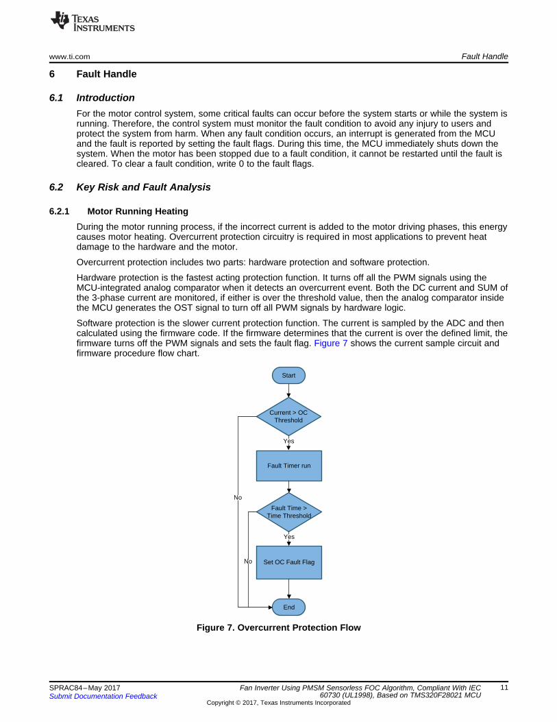
6.2.1 Motor Running HeatingDuring the motor running process, if the incorrect current is added to the motor driving phases, this energycauses motor heating. Overcurrent protection circuitry is required in most applications to prevent heatdamage to the hardware and the motor.
Overcurrent protection includes two parts: hardware protection and software protection.
Hardware protection is the fastest acting protection function. It turns off all the PWM signals using theMCU-integrated analog comparator when it detects an overcurrent event. Both the DC current and SUM ofthe 3-phase current are monitored, if either is over the threshold value, then the analog comparator insidethe MCU generates the OST signal to turn off all PWM signals by hardware logic.
Software protection is the slower current protection function. The current is sampled by the ADC and thencalculated using the firmware code. If the firmware determines that the current is over the defined limit, thefirmware turns off the PWM signals and sets the fault flag. Figure 7 shows the current sample circuit andfirmware procedure flow chart.
Figure 7. Overcurrent Protection Flow
Start
SysState=FAN_CHK_CTRL
Yes
Disable U Phase PWMEnable V Phase PWMDisable W Phase PWM
Set V Phase Duty = 6.25%
Enable U Phase PWMDisable V Phase PWMDisable W Phase PWM
Set U Phase Duty = 6.25%
Disable U Phase PWMDisable V Phase PWMEnable W Phase PWM
Set W Phase Duty = 6.25%
Phase = U Phase = V Phase = W
Dc Current < PhaseLoss Threshold
Dc Current < PhaseShort ThresholdFault Timer Run
Fault Time > Time ThresholdFault Timer Run
Fault Time > Time Threshold
Yes
Yes
Yes
Yes
Set PhaseShort Fault Flag
Set PhaseShort Fault Flag
End
No
No
Fault Handle www.ti.com
12 SPRAC84–May 2017Submit Documentation Feedback
Copyright © 2017, Texas Instruments Incorporated
Fan Inverter Using PMSM Sensorless FOC Algorithm, Compliant With IEC60730 (UL1998), Based on TMS320F28021 MCU
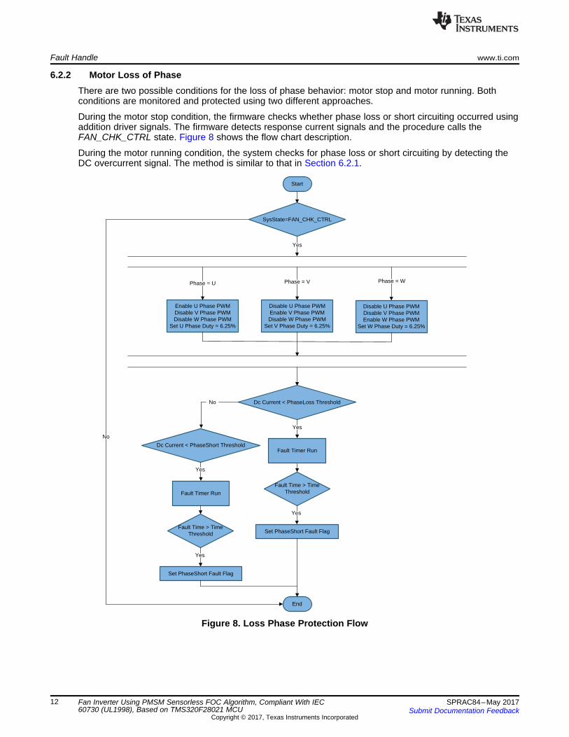
6.2.2 Motor Loss of PhaseThere are two possible conditions for the loss of phase behavior: motor stop and motor running. Bothconditions are monitored and protected using two different approaches.
During the motor stop condition, the firmware checks whether phase loss or short circuiting occurred usingaddition driver signals. The firmware detects response current signals and the procedure calls theFAN_CHK_CTRL state. Figure 8 shows the flow chart description.
During the motor running condition, the system checks for phase loss or short circuiting by detecting theDC overcurrent signal. The method is similar to that in Section 6.2.1.
Figure 8. Loss Phase Protection Flow
Start
MotorRunState = LSW_STEP_RAMP
Fault Timer Run
Fault Time > Time Threshold
Set Stall Fault Flag
MotorRunState = LSW_STEP_POSLOOP
Speed < Threshold &&Iq > IqRefMax &&
SpeedRef > ThresholdSpeed < Threshold
Fault Timer Run
End
Yes Yes
Yes Yes
Fault Time > Time Threshold
No No
No No
www.ti.com Fault Handle
13SPRAC84–May 2017Submit Documentation Feedback
Copyright © 2017, Texas Instruments Incorporated
Fan Inverter Using PMSM Sensorless FOC Algorithm, Compliant With IEC60730 (UL1998), Based on TMS320F28021 MCU
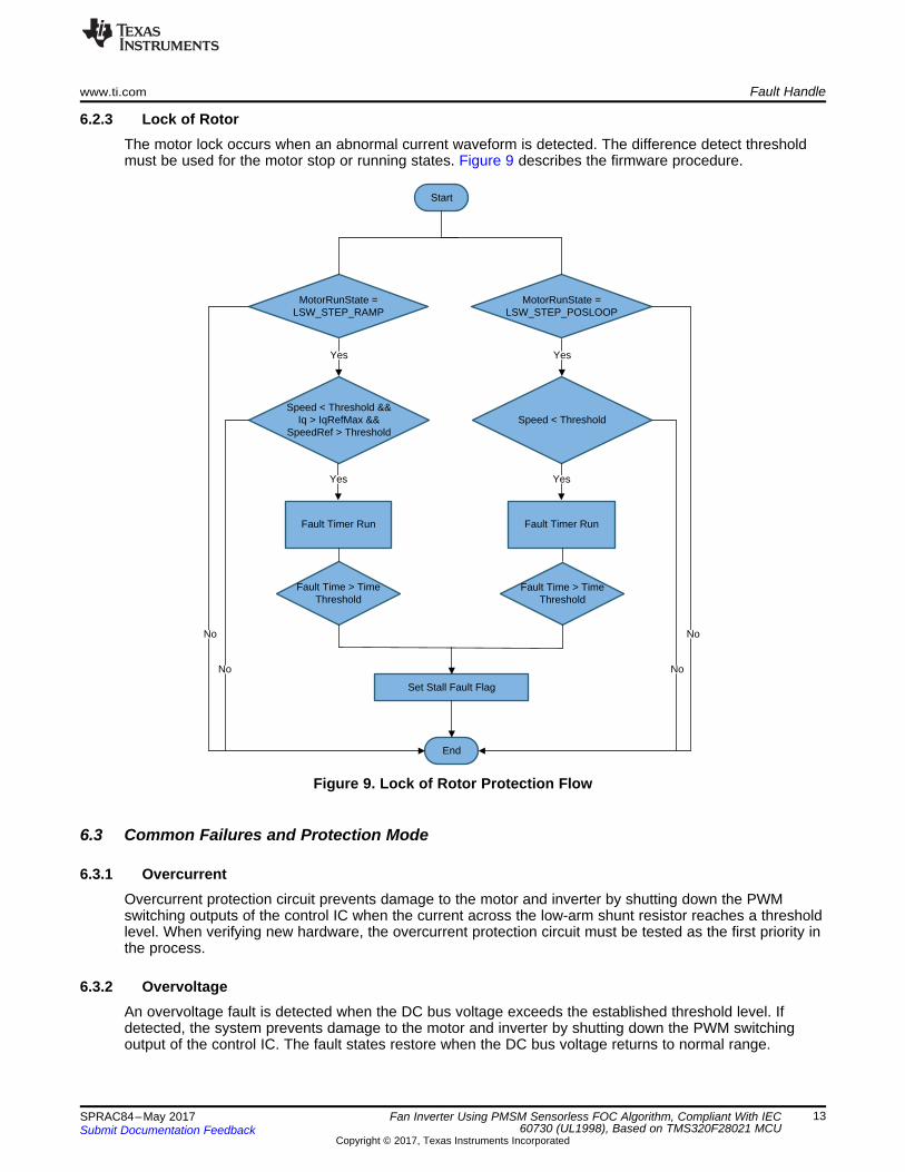
6.2.3 Lock of RotorThe motor lock occurs when an abnormal current waveform is detected. The difference detect thresholdmust be used for the motor stop or running states. Figure 9 describes the firmware procedure.
Figure 9. Lock of Rotor Protection Flow
6.3 Common Failures and Protection Mode
6.3.1 OvercurrentOvercurrent protection circuit prevents damage to the motor and inverter by shutting down the PWMswitching outputs of the control IC when the current across the low-arm shunt resistor reaches a thresholdlevel. When verifying new hardware, the overcurrent protection circuit must be tested as the first priority inthe process.
6.3.2 OvervoltageAn overvoltage fault is detected when the DC bus voltage exceeds the established threshold level. Ifdetected, the system prevents damage to the motor and inverter by shutting down the PWM switchingoutput of the control IC. The fault states restore when the DC bus voltage returns to normal range.
Fault Handle www.ti.com
14 SPRAC84–May 2017Submit Documentation Feedback
Copyright © 2017, Texas Instruments Incorporated
Fan Inverter Using PMSM Sensorless FOC Algorithm, Compliant With IEC60730 (UL1998), Based on TMS320F28021 MCU
6.3.3 UndervoltageAn undervoltage fault is detected when the DC bus voltage falls beneath the established threshold level. Ifdetected, the system prevents damage to the motor and inverter by shutting down the PWM switchingoutput of the control IC. The fault states restore when the DC bus voltage returns to normal range.
6.3.4 Start-Up FailIf the actual speed of the motor is far from the command speed, then it reaches the threshold level whenswitching from open-loop to closed-loop, and a start-up fault is detected. If detected, the system preventsdamage to the motor and inverter by shutting down the PWM switching output of the control IC. Thesystem tries to restart the motor until the motor can switch to closed-loop.
6.3.5 Stall FailThis function checks if the motor stops rotating and is executed during both start-up and normal running. Iffor some reason the rotor stops rotating and the motor speed falls below the threshold level, a stall fault isdetected. If detected, the system prevents damage to the motor and inverter by shutting down the PWMswitching output of the control IC. The system tries to restart the motor until it can run normally.
6.3.6 Current LimitationThis function checks if the motor reaches the threshold level during each phase current. It the motorreaches the threshold level, then a current limitation fault is detected. If detected, the system preventsdamage to the motor and inverter by decreasing the motor speed to keep the phase current at or belowthe threshold level. The system implements the speed limitation until the current returns to normal range.
6.3.7 Power LimitationThis function checks if the motor power consumption reaches the threshold level. If the powerconsumption reaches the threshold, then a power limitation fault is detected. If detected, the systemprevents damage to the motor and inverter by decreasing the motor speed to keep the powerconsumption at or below the threshold level. The system implements the speed limitation until the powerconsumption returns to normal range.
6.3.8 Phase LossThis function checks for phase loss, and it is executed during both during start-up and normal running.During start-up, each phase current is checked for whether it is equal to the command current. If thecurrent error is greater than the threshold level, a phase loss fault is generated.
During normal running, each phase rms current is checked for balance. If the current unbalance is greaterthan the threshold level, then a phase loss fault is generated. If detected, the system prevents damage tothe motor and inverter by shutting down the PWM switching output of the control IC. The system tries torestart the motor until the motor can switch to closed-loop.
6.3.9 OvertemperatureAn overtemperature fault is detected when the IPM temperature sensor signal reaches the establishedthreshold level. If detected, the system prevents damage to the motor and inverter by shutting down thePWM switching output of the control IC. The fault states restore when the IPM temperature sensor signalreturns to normal range.
6.3.10 Over SpeedIf the motor command speed exceeds the established threshold level, an over-speed fault is detected. Ifdetected, the system prevents damage to the motor and inverter by shutting down the PWM switchingoutput of the control IC. The fault states restore when the command speed returns to normal range.
www.ti.com Microelectronic Fault Protection Function
15SPRAC84–May 2017Submit Documentation Feedback
Copyright © 2017, Texas Instruments Incorporated
Fan Inverter Using PMSM Sensorless FOC Algorithm, Compliant With IEC60730 (UL1998), Based on TMS320F28021 MCU
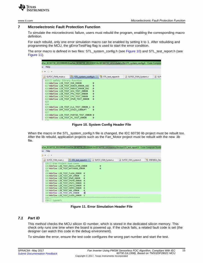
7 Microelectronic Fault Protection FunctionTo simulate the microelectronic failure, users must rebuild the program, enabling the corresponding macrodefinition.
For each rebuild, only one error simulation macro can be enabled by setting it to 1. After rebuilding andprogramming the MCU, the gErrorTestFlag flag is used to start the error condition.
The error macro is defined in two files: STL_system_config.h (see Figure 10) and STL_test_report.h (seeFigure 11).
Figure 10. System Config Header File
When the macro in the STL_system_config.h file is changed, the IEC 60730 lib project must be rebuilt too.After the lib rebuild, application projects such as the Fan_Motor project must be rebuilt with the new .libfile.
Figure 11. Error Simulation Header File
7.1 Part IDThis method checks the MCU silicon ID number, which is stored in the dedicated silicon memory. Thischeck only runs one time when the board is powered up. If the check fails, a related fault code is set (thedesigner can watch this code in the debug environment).
To simulate the error, ensure the test code configures the wrong part number and start the test.
Microelectronic Fault Protection Function www.ti.com
16 SPRAC84–May 2017Submit Documentation Feedback
Copyright © 2017, Texas Instruments Incorporated
Fan Inverter Using PMSM Sensorless FOC Algorithm, Compliant With IEC60730 (UL1998), Based on TMS320F28021 MCU
7.2 CPU TestThis function tests the CPU core registers for stuck bits periodically. The following registers are tested:• ACC• P• XAR0 to XAR7• XT• SP• IFR, IER, and DBGIER• ST0• DP
If the check fails, a related fault code is set (the designer can watch this code in the debug environment),and the motor is stopped.
Error simulation: set a different code pattern into the registers and start the tests.
7.3 PC_TESTThis function tests the program counter register for stuck bits.
If the check fails, a related fault code is set (the designer can watch this code in the debug environment),and the motor is stopped.
Error simulation: force a wrong program counter address before the test start.
7.4 RAM_TESTRAM test include the following:• Program RAM test• Data RAM test• SafeRam Stack Test• SafeRam Boot Test• SafeRam PsaCrc test• SafeRam Pie vector test• SafeRam PC test
The test writes and reads the RAM area periodically to verify the RAM functionality.
If the check fails, a related fault code is set (the designer can watch this code in the debug environment),and the motor is stopped.
Error simulation: force a wrong program counter address before the test starts.
7.5 FALSH_TESTThis function calculates the CRC value of the used flash area and checks the stored CRC valueperiodically.
If the check fails, a related fault code is set (the designer can watch this code in the debug environment),and the motor is stopped.
Error simulation: force a wrong golden code before the test starts.
7.6 SPC_TESTThis function is the MCU hardware stack watch point, which is configured to supervise the stackcorruption. If a stack corruption occurs, the SPC interrupt is generated.
If the check fails, a related fault code is set (the designer can watch this code in the debug environment),and the motor is stopped.
www.ti.com Microelectronic Fault Protection Function
17SPRAC84–May 2017Submit Documentation Feedback
Copyright © 2017, Texas Instruments Incorporated
Fan Inverter Using PMSM Sensorless FOC Algorithm, Compliant With IEC60730 (UL1998), Based on TMS320F28021 MCU
Error simulation: as the hardware watch point is configured, the SPC error occurs when the RAM stacktest executes. Normally, when the RAM stack test is processing, the SPC watch point function interruptservice routine (ISR) is ignored. For the SPC error simulation, do not ignore the stack watch pointcorruption ISR.
7.7 INTERRUPT_TESTUse the watchdog clock timer to check if the interrupt service function can be executed at the rightfrequency.
If the check fails, a related fault code is set (the designer can watch this code in the debug environment),and the motor is stopped.
Error simulation: force a wrong watch dog timer threshold before the test starts.
7.8 OSCILLATOR_TESTThis function tests whether the internal oscillator runs at the wrong frequency of 10 MHz.
If the check fails, a related fault code is set (the designer can watch this code in the debug environment),and the motor is stopped.
Error simulation: force a wrong Program counter address before the test starts.
7.9 ADC_TESTThis function tests the ADC module by measuring the ADC A0 and B1, which is linked with a 2.48-Vconstant signal, to verify the ADC functionality.
If the check fails, a related fault code is set (the designer can watch this code in the debug environment),and the motor is stopped.
Error simulation: force a wrong ADC check threshold value before the test starts.
7.10 COM_TESTThe overcurrent ADC signal is connected with two comparator modules of the MCU. The test functionchecks the output of the two compare modules. If the output of the modules is different the test fails;otherwise, the test passes.
If the check fails, a related fault code is set (the designer can watch this code in the debug environment),and the motor is stopped.
Error simulation: force a wrong comparator DVAL value to generate the wrong compare status forcomparator 1 before the test start.
7.11 WATCHDOG_TESTThis function uses the watchdog overflow interrupt to count the watchdog period count, to verify thewatchdog functionality.
If the check fails, a related fault code is set (the designer can watch this code in the debug environment),and the motor is stopped.
Error simulation: force a wrong delay time before the test starts.
7.12 TIMER_TESTThis function uses the watchdog timer count to tests CpuTimer0, CpuTimer1, and CpuTimer2.
If the check fails, a related fault code is set (the designer can watch this code in the debug environment),and the motor is stopped.
Error simulation: force a wrong watchdog timer threshold before the test starts.
Microelectronic Fault Protection Function www.ti.com
18 SPRAC84–May 2017Submit Documentation Feedback
Copyright © 2017, Texas Instruments Incorporated
Fan Inverter Using PMSM Sensorless FOC Algorithm, Compliant With IEC60730 (UL1998), Based on TMS320F28021 MCU
7.13 EPWM_TESTThis function uses the watchdog timer count to test the ePWM module period accuracy and functionality.
If the check fails, a related fault code is set (the designer can watch this code in the debug environment),and the motor is stopped.
Error simulation: force a wrong watchdog timer threshold before the test starts.
7.14 CLOCK_FAIL_DECTECTThis function uses the hardware monitor to supervise the clock missing issue. If a clock missing eventoccured, an NMI interrupt is generated.
If the check fails, a related fault code is set (the designer can watch this code in the debug environment),and the motor is stopped.
Error simulation: force the NMI clock fail flag to generate the clock fail event.
8 Final Product Performance
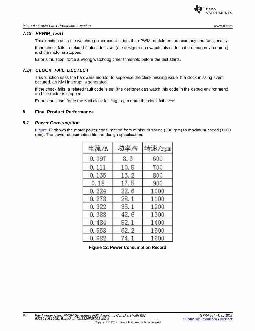
8.1 Power ConsumptionFigure 12 shows the motor power consumption from minimum speed (600 rpm) to maximum speed (1600rpm). The power consumption fits the design specification.
Figure 12. Power Consumption Record
www.ti.com Final Product Performance
19SPRAC84–May 2017Submit Documentation Feedback
Copyright © 2017, Texas Instruments Incorporated
Fan Inverter Using PMSM Sensorless FOC Algorithm, Compliant With IEC60730 (UL1998), Based on TMS320F28021 MCU
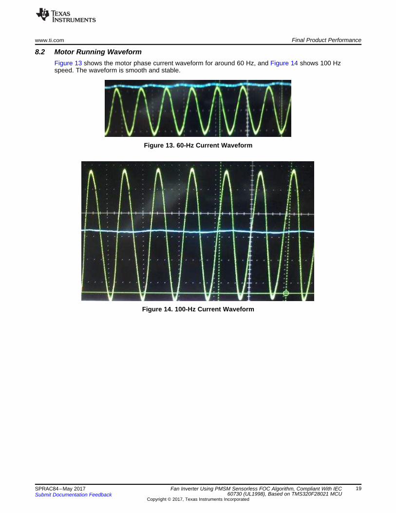
8.2 Motor Running WaveformFigure 13 shows the motor phase current waveform for around 60 Hz, and Figure 14 shows 100 Hzspeed. The waveform is smooth and stable.
Figure 13. 60-Hz Current Waveform
Figure 14. 100-Hz Current Waveform
Related Documentation www.ti.com
20 SPRAC84–May 2017Submit Documentation Feedback
Copyright © 2017, Texas Instruments Incorporated
Fan Inverter Using PMSM Sensorless FOC Algorithm, Compliant With IEC60730 (UL1998), Based on TMS320F28021 MCU
9 Related Documentation1. Texas Instruments, TMS320F2802x, Data Sheet2. Texas Instruments, TMS320F2802x, Technical Reference Manual3. Texas Instruments, Sensorless FOC of PMSM, C2000 Systems and Applications4. Texas Instruments, IEC60730_F2803x_STL_User_Manual
IMPORTANT NOTICE FOR TI DESIGN INFORMATION AND RESOURCES
Texas Instruments Incorporated (‘TI”) technical, application or other design advice, services or information, including, but not limited to,reference designs and materials relating to evaluation modules, (collectively, “TI Resources”) are intended to assist designers who aredeveloping applications that incorporate TI products; by downloading, accessing or using any particular TI Resource in any way, you(individually or, if you are acting on behalf of a company, your company) agree to use it solely for this purpose and subject to the terms ofthis Notice.TI’s provision of TI Resources does not expand or otherwise alter TI’s applicable published warranties or warranty disclaimers for TIproducts, and no additional obligations or liabilities arise from TI providing such TI Resources. TI reserves the right to make corrections,enhancements, improvements and other changes to its TI Resources.You understand and agree that you remain responsible for using your independent analysis, evaluation and judgment in designing yourapplications and that you have full and exclusive responsibility to assure the safety of your applications and compliance of your applications(and of all TI products used in or for your applications) with all applicable regulations, laws and other applicable requirements. Yourepresent that, with respect to your applications, you have all the necessary expertise to create and implement safeguards that (1)anticipate dangerous consequences of failures, (2) monitor failures and their consequences, and (3) lessen the likelihood of failures thatmight cause harm and take appropriate actions. You agree that prior to using or distributing any applications that include TI products, youwill thoroughly test such applications and the functionality of such TI products as used in such applications. TI has not conducted anytesting other than that specifically described in the published documentation for a particular TI Resource.You are authorized to use, copy and modify any individual TI Resource only in connection with the development of applications that includethe TI product(s) identified in such TI Resource. NO OTHER LICENSE, EXPRESS OR IMPLIED, BY ESTOPPEL OR OTHERWISE TOANY OTHER TI INTELLECTUAL PROPERTY RIGHT, AND NO LICENSE TO ANY TECHNOLOGY OR INTELLECTUAL PROPERTYRIGHT OF TI OR ANY THIRD PARTY IS GRANTED HEREIN, including but not limited to any patent right, copyright, mask work right, orother intellectual property right relating to any combination, machine, or process in which TI products or services are used. Informationregarding or referencing third-party products or services does not constitute a license to use such products or services, or a warranty orendorsement thereof. Use of TI Resources may require a license from a third party under the patents or other intellectual property of thethird party, or a license from TI under the patents or other intellectual property of TI.TI RESOURCES ARE PROVIDED “AS IS” AND WITH ALL FAULTS. TI DISCLAIMS ALL OTHER WARRANTIES ORREPRESENTATIONS, EXPRESS OR IMPLIED, REGARDING TI RESOURCES OR USE THEREOF, INCLUDING BUT NOT LIMITED TOACCURACY OR COMPLETENESS, TITLE, ANY EPIDEMIC FAILURE WARRANTY AND ANY IMPLIED WARRANTIES OFMERCHANTABILITY, FITNESS FOR A PARTICULAR PURPOSE, AND NON-INFRINGEMENT OF ANY THIRD PARTY INTELLECTUALPROPERTY RIGHTS.TI SHALL NOT BE LIABLE FOR AND SHALL NOT DEFEND OR INDEMNIFY YOU AGAINST ANY CLAIM, INCLUDING BUT NOTLIMITED TO ANY INFRINGEMENT CLAIM THAT RELATES TO OR IS BASED ON ANY COMBINATION OF PRODUCTS EVEN IFDESCRIBED IN TI RESOURCES OR OTHERWISE. IN NO EVENT SHALL TI BE LIABLE FOR ANY ACTUAL, DIRECT, SPECIAL,COLLATERAL, INDIRECT, PUNITIVE, INCIDENTAL, CONSEQUENTIAL OR EXEMPLARY DAMAGES IN CONNECTION WITH ORARISING OUT OF TI RESOURCES OR USE THEREOF, AND REGARDLESS OF WHETHER TI HAS BEEN ADVISED OF THEPOSSIBILITY OF SUCH DAMAGES.You agree to fully indemnify TI and its representatives against any damages, costs, losses, and/or liabilities arising out of your non-compliance with the terms and provisions of this Notice.This Notice applies to TI Resources. Additional terms apply to the use and purchase of certain types of materials, TI products and services.These include; without limitation, TI’s standard terms for semiconductor products http://www.ti.com/sc/docs/stdterms.htm), evaluationmodules, and samples (http://www.ti.com/sc/docs/sampterms.htm).
Mailing Address: Texas Instruments, Post Office Box 655303, Dallas, Texas 75265Copyright © 2017, Texas Instruments Incorporated
Related Documents