Sensored Field Oriented Control of 3-Phase Permanent Magnet Synchronous Motors Authors: Bilal Akin, Manish Bhardwaj Texas Instruments, Inc. C2000 Systems and Applications

Sensored FOC of PMSM
Feb 02, 2016
Sensored Foc of Permanent magnet Synchronous Machine
Welcome message from author
This document is posted to help you gain knowledge. Please leave a comment to let me know what you think about it! Share it to your friends and learn new things together.
Transcript
Sensored Field Oriented Control of 3-Phase Permanent Magnet Synchronous Motors
Authors: Bilal Akin, Manish Bhardwaj
Texas Instruments, Inc. C2000 Systems and Applications

2
Contents
Introduction ................................................................................................................................................ 3 PMSM Motors ............................................................................................................................................ 3 Field Oriented Control ............................................................................................................................... 5 Benefits of 32-bit C2000 Controllers for Digital Motor Control ............................................................... .11 TI Motor Control Literature and DMC Library .......................................................................................... 12 System Overview ..................................................................................................................................... 13 Hardware Configuration ........................................................................................................................... 17 Software Setup Instructions to Run HVPMSM_Sensored Project .......................................................... 20 Incremental System Build ........................................................................................................................ 22
Abstract This application note presents a solution to control a permanent magnet synchronous motor (PMSM) using the TMS320F2803x microcontrollers. TMS320F2803x devices are part of the family of C2000 microcontrollers which enable cost-effective design of intelligent controllers for three phase motors by reducing the system components and increase efficiency With these devices it is possible to realize far more precise digital vector control algorithms like the Field Orientated Control (FOC). This algorithm’s implementation is discussed in this document. The FOC algorithm maintains efficiency in a wide range of speeds and takes into consideration torque changes with transient phases by processing a dynamic model of the motor. This application note covers the following:
A theoretical background on field oriented motor control principle. Incremental build levels based on modular software blocks Experimental results

3
Introduction A brushless Permanent Magnet Synchronous motor (PMSM) has a wound stator, a permanent magnet rotor assembly and internal or external devices to sense rotor position. The sensing devices provide position feedback for adjusting frequency and amplitude of stator voltage reference properly to maintain rotation of the magnet assembly. The combination of an inner permanent magnet rotor and outer windings offers the advantages of low rotor inertia, efficient heat dissipation, and reduction of the motor size. Moreover, the elimination of brushes reduces noise, EMI generation and suppresses the need of brushes maintenance. This document presents a solution to control a permanent magnet synchronous motor using the TMS320F2803x. This new family of DSPs enables cost-effective design of intelligent controllers for brushless motors which can fulfill enhanced operations, consisting of fewer system components, lower system cost and increased performances. The control method presented relies on the field orientated control (FOC). This algorithm maintains efficiency in a wide range of speeds and takes into consideration torque changes with transient phases by controlling the flux directly from the rotor coordinates. This application report presents the implementation of a control for sinusoidal PMSM motor. The sinusoidal voltage waveform applied to this motor is created by using the Space Vector modulation technique. Minimum amount of torque ripple appears when driving this sinusoidal BEMF motor with sinusoidal currents. Permanent Magnet Motors There are primarily two types of three-phase permanent magnet synchronous motors. One uses rotor windings fed from the stator and the other uses permanent magnets. A motor fitted with rotor windings, requires brushes to obtain its current supply and generate rotor flux. The contacts are made of rings and have any commutator segments. The drawbacks of this type of structure are maintenance needs and lower reliability. Replacing the common rotor field windings and pole structure with permanent magnets puts the motor into the category of brushless motors. It is possible to build brushless permanent magnet motors with any even number of magnet poles. The use of magnets enables an efficient use of the radial space and replaces the rotor windings, therefore suppressing the rotor copper losses. Advanced magnet materials permit a considerable reduction in motor dimensions while maintaining a very high power density.
Fig. 1 A three-phase synchronous motor with a one permanent magnet pair pole rotor
4
Synchronous Motor Operation
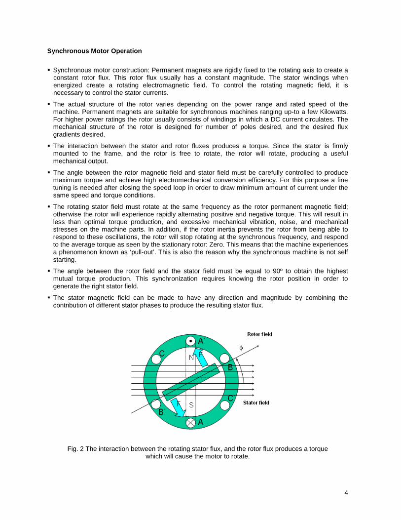
Synchronous motor construction: Permanent magnets are rigidly fixed to the rotating axis to create a constant rotor flux. This rotor flux usually has a constant magnitude. The stator windings when energized create a rotating electromagnetic field. To control the rotating magnetic field, it is necessary to control the stator currents.
The actual structure of the rotor varies depending on the power range and rated speed of the machine. Permanent magnets are suitable for synchronous machines ranging up-to a few Kilowatts. For higher power ratings the rotor usually consists of windings in which a DC current circulates. The mechanical structure of the rotor is designed for number of poles desired, and the desired flux gradients desired.
The interaction between the stator and rotor fluxes produces a torque. Since the stator is firmly mounted to the frame, and the rotor is free to rotate, the rotor will rotate, producing a useful mechanical output.
The angle between the rotor magnetic field and stator field must be carefully controlled to produce maximum torque and achieve high electromechanical conversion efficiency. For this purpose a fine tuning is needed after closing the speed loop in order to draw minimum amount of current under the same speed and torque conditions.
The rotating stator field must rotate at the same frequency as the rotor permanent magnetic field; otherwise the rotor will experience rapidly alternating positive and negative torque. This will result in less than optimal torque production, and excessive mechanical vibration, noise, and mechanical stresses on the machine parts. In addition, if the rotor inertia prevents the rotor from being able to respond to these oscillations, the rotor will stop rotating at the synchronous frequency, and respond to the average torque as seen by the stationary rotor: Zero. This means that the machine experiences a phenomenon known as ‘pull-out’. This is also the reason why the synchronous machine is not self starting.
The angle between the rotor field and the stator field must be equal to 90º to obtain the highest mutual torque production. This synchronization requires knowing the rotor position in order to generate the right stator field.
The stator magnetic field can be made to have any direction and magnitude by combining the contribution of different stator phases to produce the resulting stator flux.
Fig. 2 The interaction between the rotating stator flux, and the rotor flux produces a torque which will cause the motor to rotate.

5
Field Oriented Control
Introduction In order to achieve better dynamic performance, a more complex control scheme needs to be applied, to control the PM motor. With the mathematical processing power offered by the microcontrollers, we can implement advanced control strategies, which use mathematical transformations in order to decouple the torque generation and the magnetization functions in PM motors. Such de-coupled torque and magnetization control is commonly called rotor flux oriented control, or simply Field Oriented Control (FOC).
The main philosophy behind the FOC
In order to understand the spirit of the Field Oriented Control technique, let us start with an overview of the separately excited direct current (DC) Motor. In this type of motor, the excitation for the stator and rotor is independently controlled. Electrical study of the DC motor shows that the produced torque and the flux can be independently tuned. The strength of the field excitation (i.e. the magnitude of the field excitation current) sets the value of the flux. The current through the rotor windings determines how much torque is produced. The commutator on the rotor plays an interesting part in the torque production. The commutator is in contact with the brushes, and the mechanical construction is designed to switch into the circuit the windings that are mechanically aligned to produce the maximum torque. This arrangement then means that the torque production of the machine is fairly near optimal all the time. The key point here is that the windings are managed to keep the flux produced by the rotor windings orthogonal to the stator field.
AC machines do not have the same key features as the DC motor. In both cases we have only one source that can be controlled which is the stator currents. On the synchronous machine, the rotor excitation is given by the permanent magnets mounted onto the shaft. On the synchronous motor, the only source of power and magnetic field is the stator phase voltage. Obviously, as opposed to the DC motor, flux and torque depend on each other. The goal of the FOC (also called vector control) on synchronous and asynchronous machine is to be able to separately control the torque producing and magnetizing flux components. The control technique goal is to (in a sense), imitate the DC motor’s operation. FOC control will allow us to decouple the torque and the magnetizing flux components of stator current. With decoupled control of the magnetization, the torque producing component of the stator flux can now be thought of as independent torque control. To decouple the torque and flux, it is necessary to engage several mathematical transforms, and this is where the microcontrollers add the most value. The processing capability provided by the microcontrollers enables these mathematical transformations to be carried out very quickly. This in turn implies that the entire algorithm controlling the motor can be executed at a fast rate, enabling higher dynamic performance. In addition to the decoupling, a dynamic model of the motor is now used for the computation of many quantities such as rotor flux angle and rotor speed. This means that their effect is accounted for, and the overall quality of control is better.
Fig 3. Separated excitation DC motor model, flux and torque are independently controlled and the current through the rotor windings determines how much torque is produced.
)(..
..
e
em
IfKE
IKT
=ΦΩΦ=Φ=
Inductor (field excitation)
Armature Circuit

6
According to the electromagnetic laws, the torque produced in the synchronous machine is equal to vector cross product of the two existing magnetic fields:
rotorstatorem BBT
×= This expression shows that the torque is maximum if stator and rotor magnetic fields are orthogonal meaning if we are to maintain the load at 90 degrees. If we are able to ensure this condition all the time, if we are able to orient the flux correctly, we reduce the torque ripple and we ensure a better dynamic response. However, the constraint is to know the rotor position: this can be achieved with a position sensor such as incremental encoder. For low-cost application where the rotor is not accessible, different rotor position observer strategies are applied to get rid of position sensor. In brief, the goal is to maintain the rotor and stator flux in quadrature: the goal is to align the stator flux with the q axis of the rotor flux, i.e. orthogonal to the rotor flux. To do this the stator current component in quadrature with the rotor flux is controlled to generate the commanded torque, and the direct component is set to zero. The direct component of the stator current can be used in some cases for field weakening, which has the effect of opposing the rotor flux, and reducing the back-emf, which allows for operation at higher speeds. Technical Background The Field Orientated Control consists of controlling the stator currents represented by a vector. This control is based on projections which transform a three phase time and speed dependent system into a two co-ordinate (d and q co-ordinates) time invariant system. These projections lead to a structure similar to that of a DC machine control. Field orientated controlled machines need two constants as input references: the torque component (aligned with the q co-ordinate) and the flux component (aligned with d co-ordinate). As Field Orientated Control is simply based on projections the control structure handles instantaneous electrical quantities. This makes the control accurate in every working operation (steady state and transient) and independent of the limited bandwidth mathematical model. The FOC thus solves the classic scheme problems, in the following ways:
The ease of reaching constant reference (torque component and flux component of the stator current)
The ease of applying direct torque control because in the (d,q) reference frame the expression of the torque is:
SqR im ψ∝
By maintaining the amplitude of the rotor flux ( Rψ ) at a fixed value we have a linear relationship between torque and torque component (iSq). We can then control the torque by controlling the torque component of stator current vector.
Space Vector Definition and Projection The three-phase voltages, currents and fluxes of AC-motors can be analyzed in terms of complex space vectors. With regard to the currents, the space vector can be defined as follows. Assuming that ia, ib, ic are the instantaneous currents in the stator phases, then the complex stator current vector si is defined by:
cbas iiii 2αα ++=
where π
α 32j
e= and π
α 34
2 je= , represent the spatial operators. The following diagram shows the stator
current complex space vector:

7
Fig.4 Stator current space vector and its component in (a,b,c)
where (a,b,c) are the three phase system axes. This current space vector depicts the three phase sinusoidal system. It still needs to be transformed into a two time invariant co-ordinate system. This transformation can be split into two steps: (a,b,c) ),( βα⇒ (the Clarke transformation) which outputs a two co-ordinate time variant system ⇒),( βα (d,q) (the Park transformation) which outputs a two co-ordinate time invariant system
The (a,b,c) ),( βα⇒ Projection (Clarke transformation) The space vector can be reported in another reference frame with only two orthogonal axis called ),( βα . Assuming that the axis a and the axis α are in the same direction we have the following vector diagram:
Fig.5 Stator current space vector and its components in the stationary reference frame
The projection that modifies the three phase system into the ),( βα two dimension orthogonal system is presented below.
+=
=
bas
as
iii
ii
32
31
β
α
The two phase ),( βα currents are still depends on time and speed.

8
The ⇒),( βα (d,q) Projection (Park Transformation) This is the most important transformation in the FOC. In fact, this projection modifies a two phase orthogonal system ),( βα in the d,q rotating reference frame. If we consider the d axis aligned with the rotor flux, the next diagram shows, for the current vector, the relationship from the two reference frame:
Fig.6 Stator current space vector and its component in ),( βα and in the d,q
rotating reference frame where θ is the rotor flux position. The flux and torque components of the current vector are determined by the following equations:
+−=
+=
θθ
θθ
βα
βα
cossin
sincos
sssq
sssd
iii
iii
These components depend on the current vector ),( βα components and on the rotor flux position; if we know the right rotor flux position then, by this projection, the d,q component becomes a constant. Two phase currents now turn into dc quantity (time-invariant). At this point the torque control becomes easier where constant isd (flux component) and isq (torque component) current components controlled independently.
9
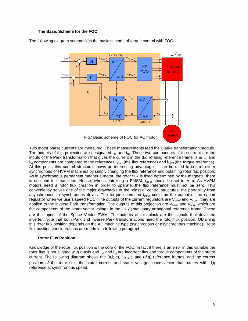
Fig7 Basic scheme of FOC for AC motor
The Basic Scheme for the FOC The following diagram summarizes the basic scheme of torque control with FOC:
Two motor phase currents are measured. These measurements feed the Clarke transformation module. The outputs of this projection are designated isα and isβ. These two components of the current are the inputs of the Park transformation that gives the current in the d,q rotating reference frame. The isd and isq components are compared to the references isdref (the flux reference) and isqref (the torque reference). At this point, this control structure shows an interesting advantage: it can be used to control either synchronous or HVPM machines by simply changing the flux reference and obtaining rotor flux position. As in synchronous permanent magnet a motor, the rotor flux is fixed determined by the magnets; there is no need to create one. Hence, when controlling a PMSM, isdref should be set to zero. As HVPM motors need a rotor flux creation in order to operate, the flux reference must not be zero. This conveniently solves one of the major drawbacks of the “classic” control structures: the portability from asynchronous to synchronous drives. The torque command isqref could be the output of the speed regulator when we use a speed FOC. The outputs of the current regulators are Vsdref and Vsqref; they are applied to the inverse Park transformation. The outputs of this projection are Vsαref and Vsβref which are the components of the stator vector voltage in the ),( βα stationary orthogonal reference frame. These are the inputs of the Space Vector PWM. The outputs of this block are the signals that drive the inverter. Note that both Park and inverse Park transformations need the rotor flux position. Obtaining this rotor flux position depends on the AC machine type (synchronous or asynchronous machine). Rotor flux position considerations are made in a following paragraph.
Rotor Flux Position
Knowledge of the rotor flux position is the core of the FOC. In fact if there is an error in this variable the rotor flux is not aligned with d-axis and isd and isq are incorrect flux and torque components of the stator current. The following diagram shows the (a,b,c), ),( βα and (d,q) reference frames, and the correct position of the rotor flux, the stator current and stator voltage space vector that rotates with d,q reference at synchronous speed.

10
Fig.9 Overall block diagram of sensored field oriented control
Fig.8 Current, voltage and rotor flux space vectors in the d,q rotating reference frame and their
relationship with a,b,c and ),( βα stationary reference frame The measure of the rotor flux position is different if we consider synchronous or asynchronous motors:
In the synchronous machine the rotor speed is equal to the rotor flux speed. Then θ (rotor flux position) is directly measured by position sensor or by integration of rotor speed.
In the asynchronous machine the rotor speed is not equal to the rotor flux speed (there is a slip speed), then it needs a particular method to calculate θ. The basic method is the use of the current model which needs two equations of the motor model in d,q reference frame.
Theoretically, the field oriented control for the PMSM drive allows the motor torque be controlled independently with the flux like DC motor operation. In other words, the torque and flux are decoupled from each other. The rotor position is required for variable transformation from stationary reference frame to synchronously rotating reference frame. As a result of this transformation (so called Park transformation), q-axis current will be controlling torque while d-axis current is forced to zero. Therefore, the key module of this system is the information of rotor position from QEP encoder. The overall block diagram of this project is depicted in Fig. 9.
11
Benefits of 32-bit C2000 Controllers for Digital Motor Control (DMC) C2000 family of devices posses the desired computation power to execute complex control algorithms along with the right mix of peripherals to interface with the various components of the DMC hardware like the ADC, ePWM, QEP, eCAP etc. These peripherals have all the necessary hooks for implementing systems which meet safety requirements, like the trip zones for PWMs and comparators. Along with this the C2000 ecosystem of software (libraries and application software) and hardware (application kits) help in reducing the time and effort needed to develop a Digital Motor Control solution. The DMC Library provides configurable blocks that can be reused to implement new control strategies. IQMath Library enables easy migration from floating point algorithms to fixed point thus accelerating the development cycle. Thus, with C2000 family of devices it is easy and quick to implement complex control algorithms (sensored and sensorless) for motor control. The use of C2000 devices and advanced control schemes provides the following system improvements
Favors system cost reduction by an efficient control in all speed range implying right dimensioning of power device circuits
Use of advanced control algorithms it is possible to reduce torque ripple, thus resulting in lower vibration and longer life time of the motor
Advanced control algorithms reduce harmonics generated by the inverter thus reducing filter cost.
Use of sensorless algorithms eliminates the need for speed or position sensor.
Decreases the number of look-up tables which reduces the amount of memory required
The Real-time generation of smooth near-optimal reference profiles and move trajectories, results in better-performance
Generation of high resolution PWM’s is possible with the use of ePWM peripheral for controlling the power switching inverters
Provides single chip control system
For advanced controls, C2000 controllers can also perform the following:
Enables control of multi-variable and complex systems using modern intelligent methods such as neural networks and fuzzy logic.
Performs adaptive control. C2000 controllers have the speed capabilities to concurrently monitor the system and control it. A dynamic control algorithm adapts itself in real time to variations in system behaviour.
Performs parameter identification for sensorless control algorithms, self commissioning, online parameter estimation update.
Performs advanced torque ripple and acoustic noise reduction.
Provides diagnostic monitoring with spectrum analysis. By observing the frequency spectrum of mechanical vibrations, failure modes can be predicted in early stages.
Produces sharp-cut-off notch filters that eliminate narrow-band mechanical resonance. Notch filters remove energy that would otherwise excite resonant modes and possibly make the system unstable.

12
TI Literature and Digital Motor Control (DMC) Library The Digital Motor Control (DMC) library is composed of functions represented as blocks. These blocks are categorized as Transforms & Estimators (Clarke, Park, Sliding Mode Observer, Phase Voltage Calculation, and Resolver, Flux, and Speed Calculators and Estimators), Control (Signal Generation, PID, BEMF Commutation, Space Vector Generation), and Peripheral Drivers (PWM abstraction for multiple topologies and techniques, ADC drivers, and motor sensor interfaces). Each block is a modular software macro is separately documented with source code, use, and technical theory. Check the folders below for the source codes and explanations of macro blocks: C:\TI\controlSUITE\libs\app_libs\motor_control\math_blocks\v4.0 C:\TI\controlSUITE\libs\app_libs\motor_control\drivers\f2803x_v2.0 These modules allow users to quickly build, or customize, their own systems. The Library supports the three motor types: ACI, BLDC, PMSM, and comprises both peripheral dependent (software drivers) and target dependent modules. The DMC Library components have been used by TI to provide system examples. At initialization all DMC Library variables are defined and inter-connected. At run-time the macro functions are called in order. Each system is built using an incremental build approach, which allows some sections of the code to be built at a time, so that the developer can verify each section of their application one step at a time. This is critical in real-time control applications where so many different variables can affect the system and many different motor parameters need to be tuned. Note: TI DMC modules are written in form of macros for optimization purposes (refer to application note SPRAAK2 for more details at TI website). The macros are defined in the header files. The user can open the respective header file and change the macro definition, if needed. In the macro definitions, there should be a backslash ”\” at the end of each line as shown below which means that the code continue in the next line. Any character including invisible ones like “space” after the backslash will cause compilation error. Therefore, make sure that the backslash is the last character in the line. In terms of code development, the macros are almost identical to C function, and the user can easily convert the macro definition to a C functions.
#define PARK_MACRO(v) \ \
v.Ds = _IQmpy(v.Alpha,v.Cosine) + _IQmpy(v.Beta,v.Sine); \ v.Qs = _IQmpy(v.Beta,v.Cosine) - _IQmpy(v.Alpha,v.Sine);
A typical DMC macro definition
13
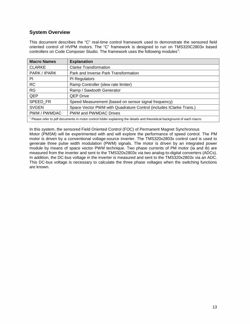
System Overview This document describes the “C” real-time control framework used to demonstrate the sensored field oriented control of HVPM motors. The “C” framework is designed to run on TMS320C2803x based controllers on Code Composer Studio. The framework uses the following modules1: Macro Names Explanation CLARKE Clarke Transformation PARK / IPARK Park and Inverse Park Transformation PI PI Regulators RC Ramp Controller (slew rate limiter) RG Ramp / Sawtooth Generator QEP QEP Drive SPEED_FR Speed Measurement (based on sensor signal frequency) SVGEN Space Vector PWM with Quadrature Control (includes IClarke Trans.) PWM / PWMDAC PWM and PWMDAC Drives 1 Please refer to pdf documents in motor control folder explaining the details and theoretical background of each macro In this system, the sensored Field Oriented Control (FOC) of Permanent Magnet Synchronous Motor (PMSM) will be experimented with and will explore the performance of speed control. The PM motor is driven by a conventional voltage-source inverter. The TMS320x2803x control card is used to generate three pulse width modulation (PWM) signals. The motor is driven by an integrated power module by means of space vector PWM technique. Two phase currents of PM motor (ia and ib) are measured from the inverter and sent to the TMS320x2803x via two analog-to-digital converters (ADCs). In addition, the DC-bus voltage in the inverter is measured and sent to the TMS320x2803x via an ADC. This DC-bus voltage is necessary to calculate the three phase voltages when the switching functions are known.

14
HVPM_Sensored project has the following properties:
C Framework
System Name Program Memory Usage 2803x
Data Memory Usage1
2803x HVPM_Sensored 3795 words2 1252 words
1 Excluding the stack size 2 Excluding “IQmath” Look-up Tables * At 10 kHz ISR frequency. Debug macros excluded (i.e. PWMDAC, Datalog and RG). IQSin/Cos tables used.
System Features Development /Emulation Code Composer Studio V4.0(or above) with Real Time debugging Target Controller TMS320F2803x PWM Frequency 10kHz PWM (Default), 60kHz PWMDAC PWM Mode Symmetrical with a programmable dead band Interrupts ADC, end of conversion – Implements 10 kHz ISR execution rate Peripherals Used PWM 1 / 2 / 3 for motor control
PWM 6A, 6B, 7A & 7B for DAC outputs QEP1 A,B, I or CAP1 ADC A7 for DC Bus voltage sensing, A1 & B1 for phase current sensing
CPU Utilization – PMSM Sensored Total Number of Cycles 725* CPU Utilization @ 60 Mhz 12.1% CPU Utilization @ 40 Mhz 18.1%
15
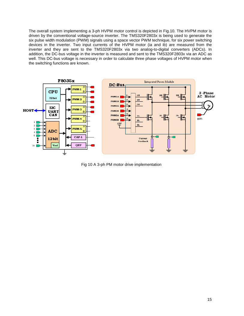
The overall system implementing a 3-ph HVPM motor control is depicted in Fig.10. The HVPM motor is driven by the conventional voltage-source inverter. The TMS320F2803x is being used to generate the six pulse width modulation (PWM) signals using a space vector PWM technique, for six power switching devices in the inverter. Two input currents of the HVPM motor (ia and ib) are measured from the inverter and they are sent to the TMS320F2803x via two analog-to-digital converters (ADCs). In addition, the DC-bus voltage in the inverter is measured and sent to the TMS320F2803x via an ADC as well. This DC-bus voltage is necessary in order to calculate three phase voltages of HVPM motor when the switching functions are known.
Fig 10 A 3-ph PM motor drive implementation

16
The software flow is described in the Figure 11 below.
c_int0
Initialize s/w modules
Initialize s/w modules
Enable end of conversion ISR
Initialize other system and module
parameters
Background Loop INT 1
SOC
EOC ISR
Save contexts and clear interrupt flag
Execute ADC conversion
Execute the park and clarke trans.
Execute the PID modules
Execute the ipark and svgen modules
Execute the QEP and speed meas.
module
Execute the PWM drive
Restore context Return

17
1 Since the motor is rated at 200V, the motor can run only at a certain speed and torque range properly without saturating the PID regulators in the control loop when the DC bus is fed from 110V AC entry. As an option, the user can run the PFC on HV DMC drive platform as boost converter to increase the DC bus voltage level or directly connect a DC power supply.
Hardware Configuration (HVDMC Kit R1.1) Please refer to the HVMotorCtrl+PFC How to Run Guide found:
C:\TI\controlSUITE\development_kits\HVMotorCtrl+PfcKit_v2.0\~Docs for an overview of the kit’s hardware and steps on how to setup this kit. Some of the hardware setup instructions are captured below for quick reference
HW Setup Instructions
1. Open the Lid of the HV Kit
2. Install the Jumpers [Main]-J3, J4 and J5, J9 for 3.3V, 5V and 15V power rails and JTAG reset line.
3. Unpack the DIMM style controlCARD and place it in the connector slot of [Main]-J1. Push vertically down using even pressure from both ends of the card until the clips snap and lock. (to remove the card simply spread open the retaining clip with thumbs)
4. Connect a USB cable to connector [M3]-JP1. This will enable isolated JTAG emulation to the C2000 device. [M3]-LD1 should turn on. Make sure [M3]-J5 is not populated. If the included Code Composer Studio is installed, the drivers for the onboard JTAG emulation will automatically be installed. If a windows installation window appears try to automatically install drivers from those already on your computer. The emulation drivers are found at http://www.ftdichip.com/Drivers/D2XX.htm. The correct driver is the one listed to support the FT2232.
5. If a third party JTAG emulator is used, connect the JTAG header to [M3]-J2 and additionally [M3]-J5 needs to be populated to put the onboard JTAG chip in reset.
6. Ensure that [M6]-SW1 is in the “Off” position. Connect 15V DC power supply to [M6]-JP1.
7. Turn on [M6]-SW1. Now [M6]-LD1 should turn on. Notice the control card LED would light up as well indicating the control card is receiving power from the board.
8. Note that the motor should be connected to the [M5]-TB3 terminals after you finish with the first incremental build step.
9. Note the DC Bus power should only be applied during incremental build levels when instructed to do so. The two options to get DC Bus power are discussed below,
(i) To use DC power supply, set the power supply output to zero and connect [Main]-BS5 and BS6 to DC power supply and ground respectively.
(ii) To use AC Mains Power, Connect [Main]-BS1 and BS5 to each other using banana plug cord. Now connect one end of the AC power cord to [Main]-P1. The other end needs to be connected to output of a variac. Make sure that the variac output is set to zero and it is connected to the wall supply through an isolator.
18
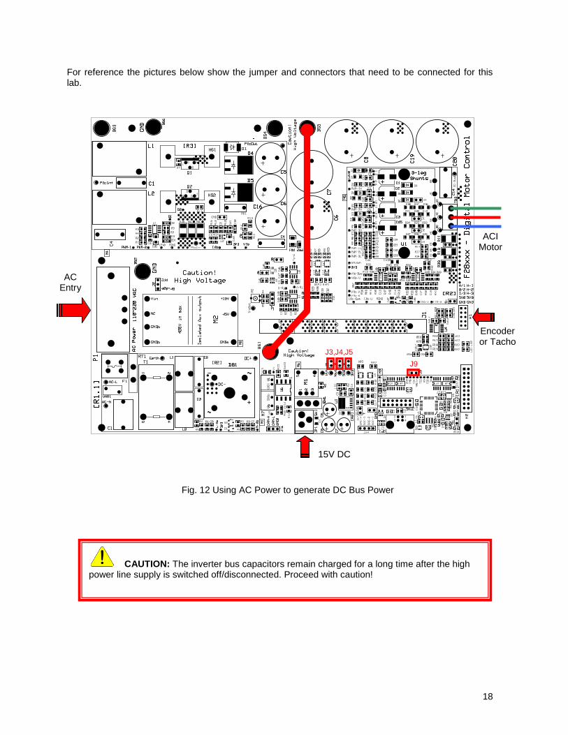
For reference the pictures below show the jumper and connectors that need to be connected for this lab.
CAUTION: The inverter bus capacitors remain charged for a long time after the high power line supply is switched off/disconnected. Proceed with caution!
ACI Motor
Encoder or Tacho
15V DC
AC Entry
J3,J4,J5 J9
Fig. 12 Using AC Power to generate DC Bus Power

19
CAUTION: The inverter bus capacitors remain charged for a long time after the high power line supply is switched off/disconnected. Proceed with caution!
ACI Motor
Encoder or Tacho
15V DC
J3,J4,J5 J9
DC Power Supply (max. 350V) + -
Fig. 13 Using External DC power supply to generate DC-Bus for the inverter
20
Software Setup Instructions to Run HVPM_Sensored Project
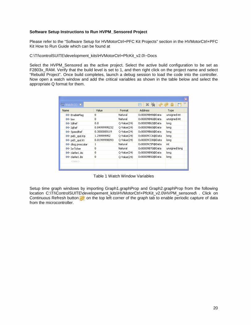
Please refer to the “Software Setup for HVMotorCtrl+PFC Kit Projects” section in the HVMotorCtrl+PFC Kit How to Run Guide which can be found at C:\TI\controlSUITE\development_kits\HVMotorCtrl+PfcKit_v2.0\~Docs Select the HVPM_Sensored as the active project. Select the active build configuration to be set as F2803x_RAM. Verify that the build level is set to 1, and then right click on the project name and select “Rebuild Project”. Once build completes, launch a debug session to load the code into the controller. Now open a watch window and add the critical variables as shown in the table below and select the appropriate Q format for them.
Table 1 Watch Window Variables
Setup time graph windows by importing Graph1.graphProp and Graph2.graphProp from the following location C:\TI\ControlSUITE\developement_kits\HVMotorCtrl+PfcKit_v2.0\HVPM_sensored\ . Click on Continuous Refresh button on the top left corner of the graph tab to enable periodic capture of data from the microcontroller.
21
Incremental System Build
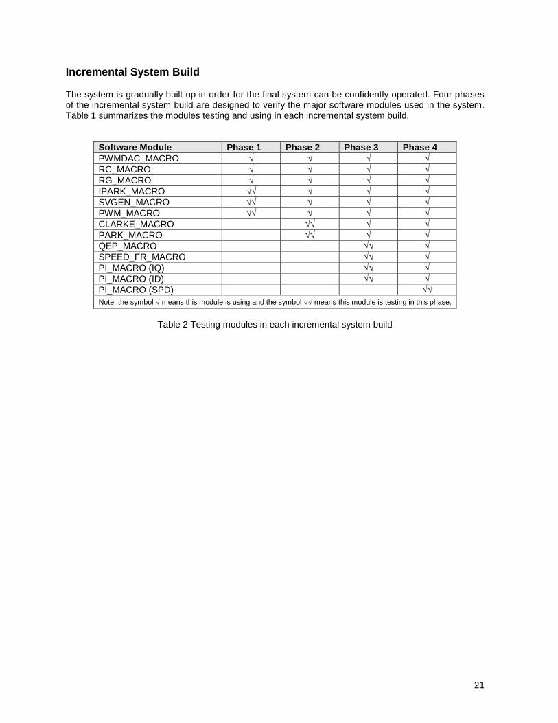
The system is gradually built up in order for the final system can be confidently operated. Four phases of the incremental system build are designed to verify the major software modules used in the system. Table 1 summarizes the modules testing and using in each incremental system build.
Software Module Phase 1 Phase 2 Phase 3 Phase 4 PWMDAC_MACRO √ √ √ √ RC_MACRO √ √ √ √ RG_MACRO √ √ √ √ IPARK_MACRO √√ √ √ √ SVGEN_MACRO √√ √ √ √ PWM_MACRO √√ √ √ √ CLARKE_MACRO √√ √ √ PARK_MACRO √√ √ √ QEP_MACRO √√ √ SPEED_FR_MACRO √√ √ PI_MACRO (IQ) √√ √ PI_MACRO (ID) √√ √ PI_MACRO (SPD) √√ Note: the symbol √ means this module is using and the symbol √√ means this module is testing in this phase.
Table 2 Testing modules in each incremental system build
22
Level 1 Incremental Build
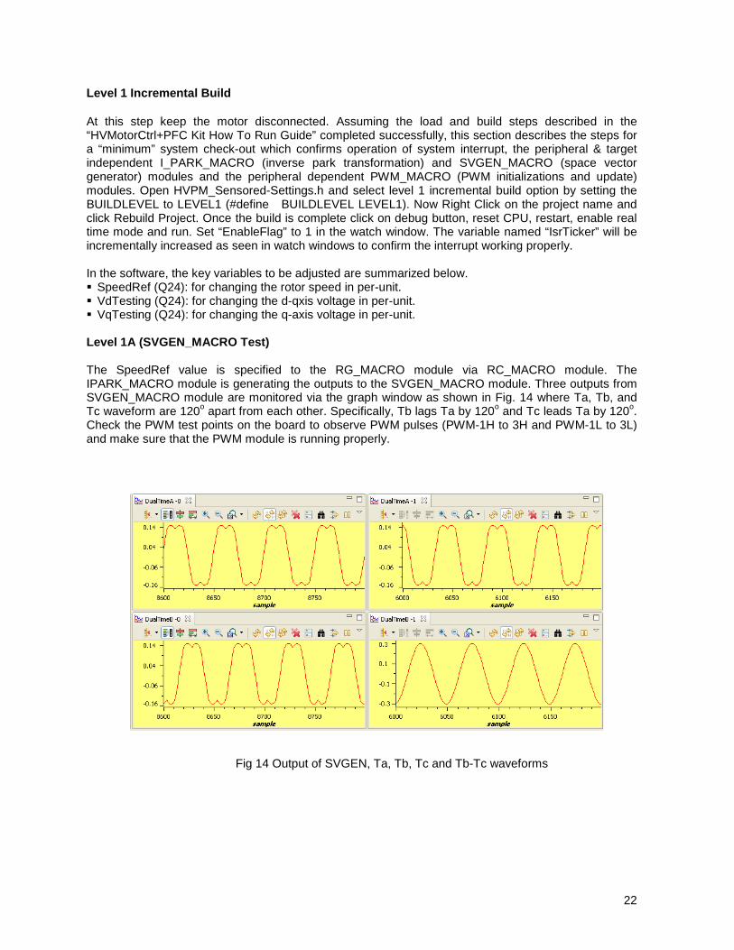
At this step keep the motor disconnected. Assuming the load and build steps described in the “HVMotorCtrl+PFC Kit How To Run Guide” completed successfully, this section describes the steps for a “minimum” system check-out which confirms operation of system interrupt, the peripheral & target independent I_PARK_MACRO (inverse park transformation) and SVGEN_MACRO (space vector generator) modules and the peripheral dependent PWM_MACRO (PWM initializations and update) modules. Open HVPM_Sensored-Settings.h and select level 1 incremental build option by setting the BUILDLEVEL to LEVEL1 (#define BUILDLEVEL LEVEL1). Now Right Click on the project name and click Rebuild Project. Once the build is complete click on debug button, reset CPU, restart, enable real time mode and run. Set “EnableFlag” to 1 in the watch window. The variable named “IsrTicker” will be incrementally increased as seen in watch windows to confirm the interrupt working properly. In the software, the key variables to be adjusted are summarized below. SpeedRef (Q24): for changing the rotor speed in per-unit. VdTesting (Q24): for changing the d-qxis voltage in per-unit. VqTesting (Q24): for changing the q-axis voltage in per-unit. Level 1A (SVGEN_MACRO Test) The SpeedRef value is specified to the RG_MACRO module via RC_MACRO module. The IPARK_MACRO module is generating the outputs to the SVGEN_MACRO module. Three outputs from SVGEN_MACRO module are monitored via the graph window as shown in Fig. 14 where Ta, Tb, and Tc waveform are 120o apart from each other. Specifically, Tb lags Ta by 120o and Tc leads Ta by 120o. Check the PWM test points on the board to observe PWM pulses (PWM-1H to 3H and PWM-1L to 3L) and make sure that the PWM module is running properly.
Fig 14 Output of SVGEN, Ta, Tb, Tc and Tb-Tc waveforms
23
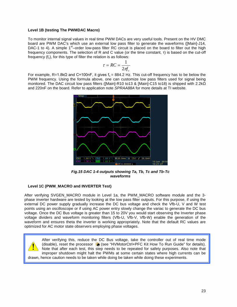
Level 1B (testing The PWMDAC Macro) To monitor internal signal values in real time PWM DACs are very useful tools. Present on the HV DMC board are PWM DAC’s which use an external low pass filter to generate the waveforms ([Main]-J14, DAC-1 to 4). A simple 1st–order low-pass filter RC circuit is placed on the board to filter out the high frequency components. The selection of R and C value (or the time constant, τ) is based on the cut-off frequency (fc), for this type of filter the relation is as follows:
cfRC
πτ
21
==
For example, R=1.8kΩ and C=100nF, it gives fc = 884.2 Hz. This cut-off frequency has to be below the PWM frequency. Using the formula above, one can customize low pass filters used for signal being monitored. The DAC circuit low pass filters ([Main]-R10 to13 & [Main]-C15 to18) is shipped with 2.2kΩ and 220nF on the board. Refer to application note SPRAA88A for more details at TI website. Level 1C (PWM_MACRO and INVERTER Test)
After verifying SVGEN_MACRO module in Level 1a, the PWM_MACRO software module and the 3-phase inverter hardware are tested by looking at the low pass filter outputs. For this purpose, if using the external DC power supply gradually increase the DC bus voltage and check the Vfb-U, V and W test points using an oscilloscope or if using AC power entry slowly change the variac to generate the DC bus voltage. Once the DC Bus voltage is greater than 15 to 20V you would start observing the Inverter phase voltage dividers and waveform monitoring filters (Vfb-U, Vfb-V, Vfb-W) enable the generation of the waveform and ensures theta the inverter is working appropriately. Note that the default RC values are optimized for AC motor state observers employing phase voltages.
After verifying this, reduce the DC Bus voltage, take the controller out of real time mode (disable), reset the processor (see “HVMotorCtrl+PFC Kit How To Run Guide” for details). Note that after each test, this step needs to be repeated for safety purposes. Also note that improper shutdown might halt the PWMs at some certain states where high currents can be
drawn, hence caution needs to be taken while doing be taken while doing these experiments.
Fig.15 DAC 1-4 outputs showing Ta, Tb, Tc and Tb-Tc waveforms

24
SVGENMACRO
PWM1 A/B
PWM2 A/B
PWM3 A/B
Mfunc_C1
Mfunc_C3
Mfunc_C2
Ta
Tc
TbUalpha
Ubeta
PWMDACMACRO MFuncC1
MFuncC2
PWMxA
PWMxB
Low Pass Filter Cct
DATALOG
Dlog1
Dlog2
Dlog3
Dlog4
Level 1 - Incremental System Build Block Diagram
Level 1 verifies the target independent modules, duty cycles and PWM updates. The motor is disconnected at this level.
Scope Graph Window
Alpha
Beta
IPARKMACRO
Ds
Angle
QsVdTesting
VqTesting
TargetValue
RCMACRO
SetPointValue
RGMACRO
Freq
SpeedRefWatch
Window
PWM MACRO
PWMHW
25
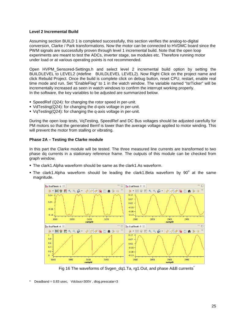
Level 2 Incremental Build Assuming section BUILD 1 is completed successfully, this section verifies the analog-to-digital conversion, Clarke / Park transformations. Now the motor can be connected to HVDMC board since the PWM signals are successfully proven through level 1 incremental build. Note that the open loop experiments are meant to test the ADCs, inverter stage, sw modules etc. Therefore running motor under load or at various operating points is not recommended. Open HVPM_Sensored-Settings.h and select level 2 incremental build option by setting the BUILDLEVEL to LEVEL2 (#define BUILDLEVEL LEVEL2). Now Right Click on the project name and click Rebuild Project. Once the build is complete click on debug button, reset CPU, restart, enable real time mode and run. Set “EnableFlag” to 1 in the watch window. The variable named “IsrTicker” will be incrementally increased as seen in watch windows to confirm the interrupt working properly. In the software, the key variables to be adjusted are summarized below. SpeedRef (Q24): for changing the rotor speed in per-unit. VdTesting(Q24): for changing the d-qxis voltage in per-unit. VqTesting(Q24): for changing the q-axis voltage in per-unit. During the open loop tests, VqTesting, SpeedRef and DC Bus voltages should be adjusted carefully for PM motors so that the generated Bemf is lower than the average voltage applied to motor winding. This will prevent the motor from stalling or vibrating. Phase 2A – Testing the Clarke module In this part the Clarke module will be tested. The three measured line currents are transformed to two phase dq currents in a stationary reference frame. The outputs of this module can be checked from graph window.
The clark1.Alpha waveform should be same as the clark1.As waveform.
The clark1.Alpha waveform should be leading the clark1.Beta waveform by 90o at the same magnitude.
* Deadband = 0.83 usec, Vdcbus=300V , dlog.prescalar=3
Fig 16 The waveforms of Svgen_dq1.Ta, rg1.Out, and phase A&B currents*
26
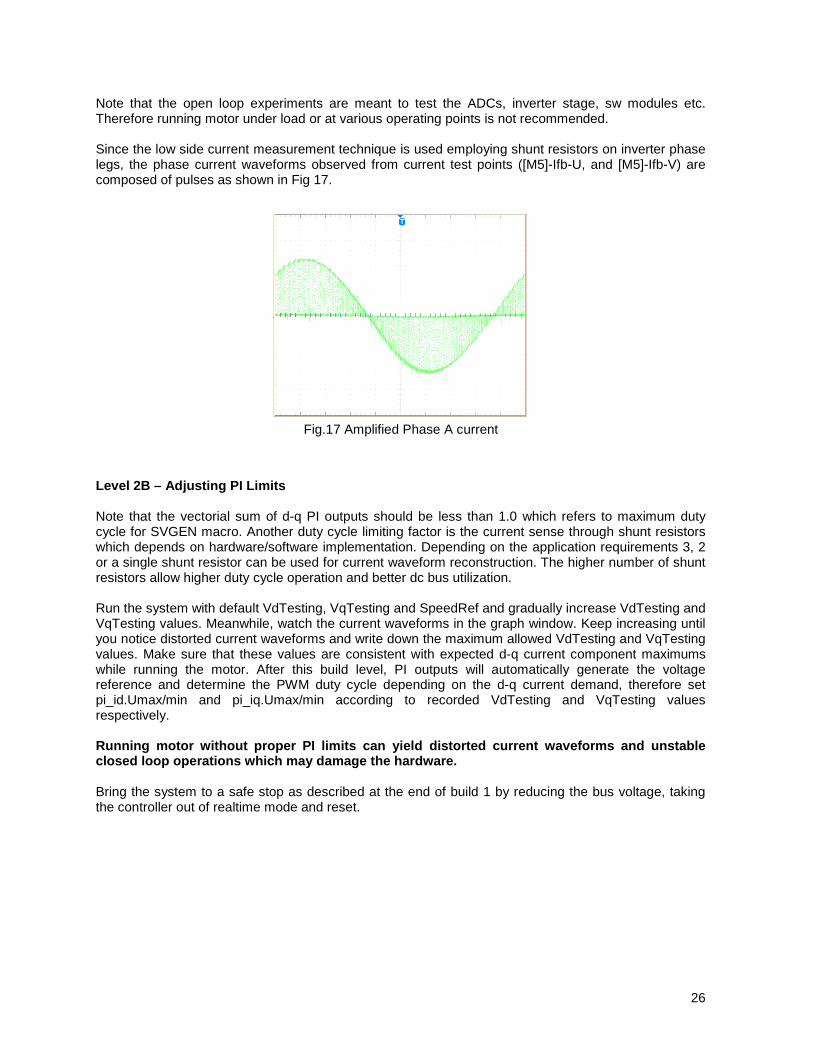
Note that the open loop experiments are meant to test the ADCs, inverter stage, sw modules etc. Therefore running motor under load or at various operating points is not recommended. Since the low side current measurement technique is used employing shunt resistors on inverter phase legs, the phase current waveforms observed from current test points ([M5]-Ifb-U, and [M5]-Ifb-V) are composed of pulses as shown in Fig 17. Level 2B – Adjusting PI Limits Note that the vectorial sum of d-q PI outputs should be less than 1.0 which refers to maximum duty cycle for SVGEN macro. Another duty cycle limiting factor is the current sense through shunt resistors which depends on hardware/software implementation. Depending on the application requirements 3, 2 or a single shunt resistor can be used for current waveform reconstruction. The higher number of shunt resistors allow higher duty cycle operation and better dc bus utilization. Run the system with default VdTesting, VqTesting and SpeedRef and gradually increase VdTesting and VqTesting values. Meanwhile, watch the current waveforms in the graph window. Keep increasing until you notice distorted current waveforms and write down the maximum allowed VdTesting and VqTesting values. Make sure that these values are consistent with expected d-q current component maximums while running the motor. After this build level, PI outputs will automatically generate the voltage reference and determine the PWM duty cycle depending on the d-q current demand, therefore set pi_id.Umax/min and pi_iq.Umax/min according to recorded VdTesting and VqTesting values respectively. Running motor without proper PI limits can yield distorted current waveforms and unstable closed loop operations which may damage the hardware. Bring the system to a safe stop as described at the end of build 1 by reducing the bus voltage, taking the controller out of realtime mode and reset.
Fig.17 Amplified Phase A current
27
SVGENMACRO
PWM1 A/B
PWM2 A/B
PWM3 A/B
Mfunc_C1
Mfunc_C3
Mfunc_C2
Ta
Tc
TbUalpha
Ubeta
PWMDACMACRO MFuncC1
MFuncC2
PWMxA
PWMxB
Low Pass Filter Cct
DATALOG
Dlog1
Dlog2
Dlog3
Dlog4
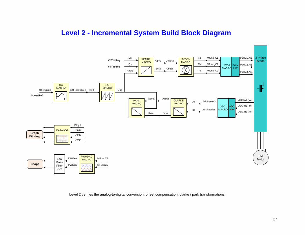
Level 2 - Incremental System Build Block Diagram
Level 2 verifies the analog-to-digital conversion, offset compensation, clarke / park transformations.
Scope
Graph Window
Alpha
Beta
Ds
Angle
QsVdTesting
VqTesting
TargetValue
RCMACRO
SetPointValue
RGMACRO
Freq
SpeedRef
PMMotor
3-Phase Inverter
PWM MACRO
PWMHW
ADCIn1 (Ia)
ADCIn2 (Ib)
ADCIn3 (Ic)
ADC MACRO
ADCHW
IPARKMACRO
CLARKEMACRO
AdcResult0
AdcResult1
As
Bs
Alpha
Beta
PARKMACRO
Alpha
Beta
Out

28
Level 3 Incremental Build Assuming the previous section is completed successfully, this section verifies the dq-axis current regulation performed by PI modules and speed measurement modules. To confirm the operation of current regulation, the gains of these two PI controllers are necessarily tuned for proper operation. Open HVPM_Sensored-Settings.h and select level 3 incremental build option by setting the BUILDLEVEL to LEVEL3 (#define BUILDLEVEL LEVEL3). Now Right Click on the project name and click Rebuild Project. Once the build is complete click on debug button, reset CPU, restart, enable real time mode and run. Set “EnableFlag” to 1 in the watch window. The variable named “IsrTicker” will be incrementally increased as seen in watch windows to confirm the interrupt working properly. In the software, the key variables to be adjusted are summarized below. SpeedRef (Q24): for changing the rotor speed in per-unit. IdRef(Q24): for changing the d-qxis voltage in per-unit. IqRef(Q24): for changing the q-axis voltage in per-unit. In this build, the motor is supplied by AC input voltage and the PM motor current is dynamically regulated by using PI module through the park transformation on the motor currents. The steps are explained as follows:
Compile/load/run program with real time mode.
Set SpeedRef to 0.3 pu (or another suitable value if the base speed is different), Idref to zero and Iqref to 0.05 pu (or another suitable value).
Gradually increase voltage at variac / dc power supply to get an appropriate DC-bus voltage.
Check pi_id.Fdb in the watch windows with continuous refresh feature whether or not it should be keeping track pi_id.Ref for PI module. If not, adjust its PI gains properly.
Check pi_iq.Fdb in the watch windows with continuous refresh feature whether or not it should be keeping track pi_iq.Ref for PI module. If not, adjust its PI gains properly.
To confirm these two PI modules, try different values of pi_id.Ref and pi_iq.Ref or SpeedRef.
For both PI controllers, the proportional, integral, derivative and integral correction gains may be re-tuned to have the satisfied responses.
Bring the system to a safe stop as described at the end of build 1 by reducing the bus voltage, taking the controller out of realtime mode and reset. Now the motor is stopping.
29
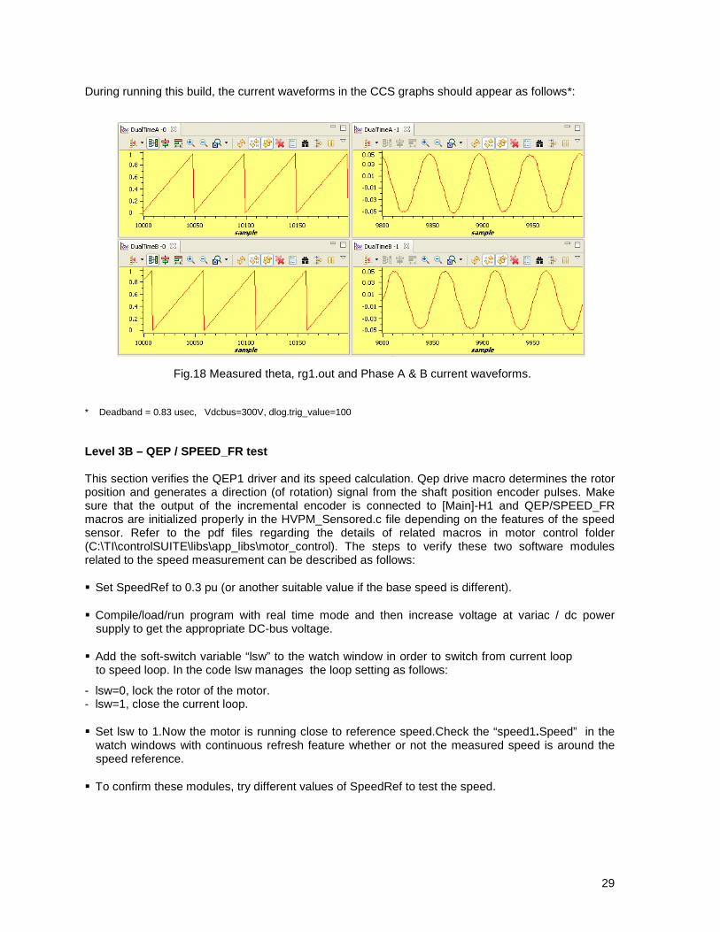
During running this build, the current waveforms in the CCS graphs should appear as follows*: * Deadband = 0.83 usec, Vdcbus=300V, dlog.trig_value=100 Level 3B – QEP / SPEED_FR test This section verifies the QEP1 driver and its speed calculation. Qep drive macro determines the rotor position and generates a direction (of rotation) signal from the shaft position encoder pulses. Make sure that the output of the incremental encoder is connected to [Main]-H1 and QEP/SPEED_FR macros are initialized properly in the HVPM_Sensored.c file depending on the features of the speed sensor. Refer to the pdf files regarding the details of related macros in motor control folder (C:\TI\controlSUITE\libs\app_libs\motor_control). The steps to verify these two software modules related to the speed measurement can be described as follows:
Set SpeedRef to 0.3 pu (or another suitable value if the base speed is different).
Compile/load/run program with real time mode and then increase voltage at variac / dc power supply to get the appropriate DC-bus voltage.
Add the soft-switch variable “lsw” to the watch window in order to switch from current loop to speed loop. In the code lsw manages the loop setting as follows:
- lsw=0, lock the rotor of the motor. - lsw=1, close the current loop.
Set lsw to 1.Now the motor is running close to reference speed.Check the “speed1.Speed” in the watch windows with continuous refresh feature whether or not the measured speed is around the speed reference.
To confirm these modules, try different values of SpeedRef to test the speed.
Fig.18 Measured theta, rg1.out and Phase A & B current waveforms.

30
Use oscilloscope to view the electrical angle output, ElecTheta, from QEP_MACRO module and the emulated rotor angle, rg1.Out, from RG_MACRO at PWMDAC outputs with external low-pass filters.
Check that both qep1.ElecTheta and rg1.Out are of saw-tooth wave shape and have the same period. If the measured angle is in opposite direction, then change the order of motor cables connected to inverter output (TB3 for HVDMC kit).
Check from Watch Window that qep1.IndexSyncFlag is set back to 0xF0 every time it reset to 0 by hand. Add the variable to the watch window if it is not already in the watch window.
Qep1.ElecTheta should be slightly lagging rg1.out, if the calibration angle needs to be adjusted due to the angle offset between index and locked rotor position.
Bring the system to a safe stop as described at the end of build 1 by reducing the bus voltage, taking the controller out of realtime mode and reset.
Next, the following steps are to verify and or perform calibration angle of the encoder. The steps are as follows:
Make sure EQep1Regs.QPOSCNT, EQep1Regs.QPOSILAT, Init_IFlag, qep1.CalibratedAngle, and lsw are displayed in watch window.
Set SpeedRef to 0.3 pu (or another suitable value if the base speed is different).
Compile/load/run program with real time mode and then increase voltage at variac / dc power supply to get the appropriate DC-bus voltage.
Now the rotor should be locked. Set lsw to 1 to spin the motor. When the first index signal is detected by QEP, the EQep1Regs.QPOSILAT register latches the angle offset in between initial rotor position and encoder index in the code. Later, EQep1Regs.QPOSILAT is set to maximum of EQep1Regs.QPOSCNT as it latches the counter value for each index signal. In the code qep1.CalibratedAngle keeps the initial offset value. This value can be recorded to initialize qep1.CalibratedAngle at the initialization section in HVPM_Sensored.c or it can be detected in the code each time the motor is restarted. The calibration angle might be different for different start-ups and can be formulated as follows:
Calibration Angle = Offset Angle ± n . Line Encoder
In the next section fine tune the detected calibration angle until minimum power is drawn under certain speed-load conditions for precise field orientation.
31
SVGENMACRO
PWM1 A/B
PWM2 A/B
PWM3 A/B
Mfunc_C1
Mfunc_C3
Mfunc_C2
Ta
Tc
TbUalpha
Ubeta
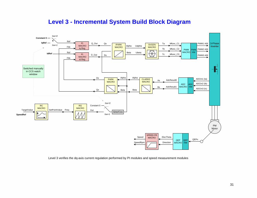
Level 3 - Incremental System Build Block Diagram
Level 3 verifies the dq-axis current regulation performed by PI modules and speed measurement modules
Alpha
Beta
Qs
Ds
IqRef
IdRef
TargetValue
RCMACRO
SetPointValue
RGMACRO
Freq
SpeedRef
PMMotor
3-Phase Inverter
PWM MACRO
PWMHW
ADCIn1 (Ia)
ADCIn2 (Ib)
ADCIn3 (Ic)
ADC MACRO
ADCHW
IPARKMACRO
CLARKEMACRO
AdcResult0
AdcResult1
As
Bs
Alpha
Beta
PARKMACRO
Alpha
Beta
QEPn
SPEED FRMACRO ElecTheta
DirectionQEP
MACROQEPHW
Speed
SpeedRpm
Q_OutRef
PI MACROIq Reg
PI MACROId Reg
D_Out
Fbk
Ref
Fbk
OutSine/Cos
Ds
Qs
Constant 0lsw=0
lsw=1
Constant 0lsw=0
lsw=1
Switched manually in CCS watch
window

32
Level 4 Incremental Build
Assuming the previous section is completed successfully; this section verifies the speed PI module and speed loop. Open HVPM_Sensored-Settings.h and select level 4 incremental build option by setting the BUILDLEVEL to LEVEL4 (#define BUILDLEVEL LEVEL4). Now Right Click on the project name and click Rebuild Project. Once the build is complete click on debug button, reset CPU, restart, enable real time mode and run. Set “EnableFlag” to 1 in the watch window. The variable named “IsrTicker” will be incrementally increased as seen in watch windows to confirm the interrupt working properly. In the software, the key variables to be adjusted are summarized below. SpeedRef (Q24): for changing the rotor speed in per-unit. IdRef (Q24): for changing the d-qxis voltage in per-unit. IqRef (Q24): for changing the q-axis voltage in per-unit. The key steps can be explained as follows:
Set Compile/load/run program with real time mode.
Set SpeedRef to 0.3 pu (or another suitable value if the base speed is different).
Gradually increase voltage at variac to get an appropriate DC-bus voltage and now the motor is running with this reference speed (0.3 pu).
Add the soft-switch variable “lsw” to the watch window in order to switch from current loop to speed loop. In the code lsw manages the loop setting as follows:
- lsw=0, lock the rotor of the motor. - lsw=1, close the current loop - lsw=2, close the speed loop (sensored FOC).
Set lsw to 1.Compare Speed with SpeedRef in the watch windows with continuous refresh feature whether or not it should be nearly the same.
To confirm this speed PI module, close the speed loop by setting lsw to 2 and try different values of SpeedRef (positive or negative).For speed PI controller, the proportional, integral, derivative and integral correction gains may be re-tuned to have the satisfied responses.
At very low speed range, the performance of speed response relies heavily on the good rotor position angle provided by QEP encoder.
Bring the system to a safe stop as described at the end of build 1 by reducing the bus voltage, taking the controller out of realtime mode and reset. Now the motor is stopping.
LEVEL 4B
Once the tuning process is completed, the motor can directly startup with closed speed loop as shown in the second block diagram (4B). During the direct startup, use the calibration angle detected in the previous level as initial value of qep1. CalibratedAngle and by-pass the calibration angle detection.
33
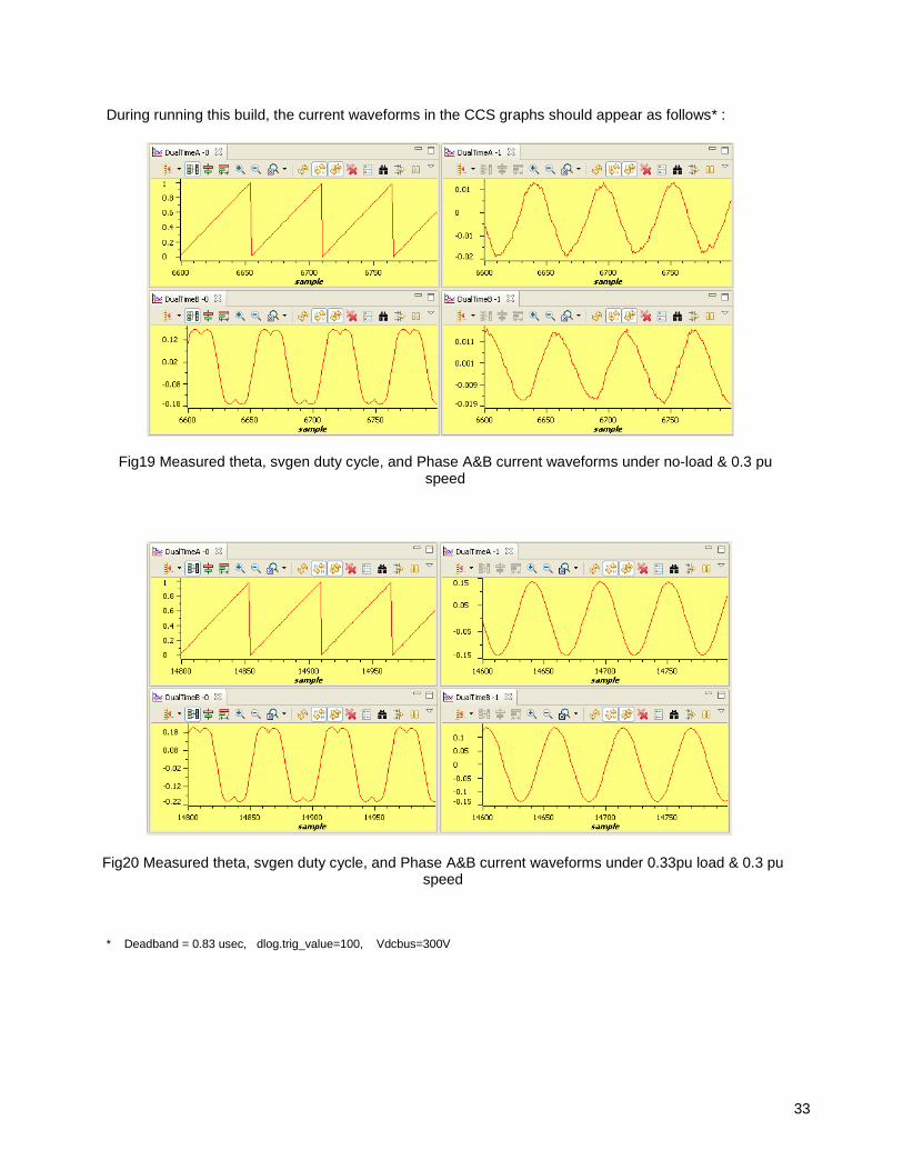
During running this build, the current waveforms in the CCS graphs should appear as follows* :
* Deadband = 0.83 usec, dlog.trig_value=100, Vdcbus=300V
Fig20 Measured theta, svgen duty cycle, and Phase A&B current waveforms under 0.33pu load & 0.3 pu speed
Fig19 Measured theta, svgen duty cycle, and Phase A&B current waveforms under no-load & 0.3 pu speed
34
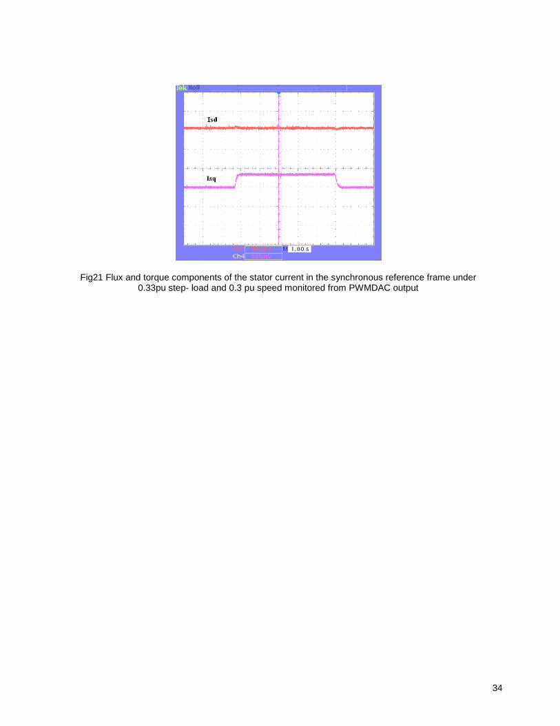
Fig21 Flux and torque components of the stator current in the synchronous reference frame under 0.33pu step- load and 0.3 pu speed monitored from PWMDAC output

35
SVGENMACRO
PWM1 A/B
PWM2 A/B
PWM3 A/B
Mfunc_C1
Mfunc_C3
Mfunc_C2
Ta
Tc
TbUalpha
Ubeta
Level 4A - Incremental System Build Block Diagram
Level 4 verifies the speed PI module and speed loop
Alpha
Beta
Qs
Ds
IqRef
IdRef
TargetValue
RCMACRO
SetPointValue
RGMACRO
Freq
SpeedRef
PMMotor
3-Phase Inverter
PWM MACRO
PWMHW
ADCIn1 (Ia)
ADCIn2 (Ib)
ADCIn3 (Ic)
ADC MACRO
ADCHW
IPARKMACRO
CLARKEMACRO
AdcResult0
AdcResult1
As
Bs
Alpha
Beta
PARKMACRO
Alpha
Beta
QEPn
SPEED FRMACRO ElecTheta
DirectionQEP
MACROQEPHW
Speed
SpeedRpm
Q_OutRef
PI MACROIq Reg
PI MACROId Reg
D_Out
Fbk
Ref
Fbk
OutSine/Cos
Ds
Qs
Constant 0 lsw=0
lsw=1
Constant 0 lsw=0
lsw=1
Switched manually in CCS watch
window
PI MACROSpd Reg Spd_Out
Ref
Fbk
SpeedRef
lsw=2
ElecTheta lsw=2

36
SVGENMACRO
PWM1 A/B
PWM2 A/B
PWM3 A/B
Mfunc_C1
Mfunc_C3
Mfunc_C2
Ta
Tc
TbUalpha
Ubeta
Level 4B - Incremental System Build Block Diagram
Level 4 verifies the speed PI module and speed loop
Alpha
Beta
Qs
Ds
IqRef
IdRef
PMMotor
3-Phase Inverter
PWM MACRO
PWMHW
ADCIn1 (Ia)
ADCIn2 (Ib)
ADCIn3 (Ic)
ADC MACRO
ADCHW
IPARKMACRO
CLARKEMACRO
AdcResult0
AdcResult1
As
Bs
Alpha
Beta
PARKMACRO
Alpha
Beta
QEPn
SPEED FRMACRO ElecTheta
DirectionQEP
MACROQEPHW
Speed
SpeedRpm
Q_OutRef
PI MACROIq Reg
PI MACROId Reg
D_Out
Fbk
Ref
Fbk
Sine/Cos
Ds
Qs
Constant 0 lsw=0
lsw=1
Constant 0 lsw = 0
Switched manually in CCS watch
window
PI MACROSpd Reg Spd_Out
Ref
Fbk
SpeedRef
lsw=2
ElecTheta lsw = 1, 2

Related Documents