XXX-X-XXXX-XXXX-X/XX/$XX.00 ©20XX IEEE SENSORLESS LOW SPEED PMSM MOTOR CONTROL WITH COGGING TORQUE COMPENSATION Jarosław Guziński Wydział Elektrotechniki i Automatyki Politechnika Gdańska Gdansk, Poland [email protected] Krzysztof Łuksza Wydział Elektrotechniki i Automatyki Politechnika Gdańska Gdansk, Poland [email protected] Marcin Morawiec Wydział Elektrotechniki i Automatyki Politechnika Gdańska Gdansk, Poland [email protected] Patryk Strankowski Wydział Elektrotechniki i Automatyki Politechnika Gdańska Gdansk, Poland [email protected] Zbigniew Krzemiński Wydział Elektrotechniki i Automatyki Politechnika Gdańska Gdansk, Poland [email protected] Abdellah Kouzou Faculty of Sciences and Technology, Ziane Achour University of Djelfa, Djelfa, Algiera [email protected] Abstract—The paper presents sensorless control of a low- speed permanent magnet synchronous machine with use of modified state observer. An overview of the PMSM motor used in the research setup was presented. The problem of drive torque ripple, resulting mainly from the occurrence of a significant cogging torque, was discussed. A solution compensating the torque ripple of the PMSM motor was proposed. A start-up procedure of the speed control system, allowing to run the drive system without speed and position sensors, was prepared. The field-oriented control with PI controllers of stator currents in the dq axes was implemented. The equations of a new, simplified version of the Krzeminski observer were presented. The observer has simpler structure of the gains, thus it is less computationally-intensive and easier to tune. The experimental results confirming the correct operation of the drive system were shown. Keywords—Permanent Magnet Synchronous Machine, PMSM, state observer, field oriented control, cogging torque. I. INTRODUCTION The Permanent Magnet Synchronous Motors (PMSM) are used in many industrial applications, especially those requiring high driving parameters, such as precise speed control and high operation dynamics [1], [2]. Most often these machines are used in direct drives, i.e. without mechanical gear usage, where a low-speed motor is connected directly to the load, and the rotational speed does not exceed several hundred rpm [10]. Low-speed drives allow increasing the efficiency of energy conversion by eliminating the mechanical transmission power losses. These drives are most often used in: numerically controlled machine tools, robotic drives, printing machines, bending machines, etc. as well traction vehicles [2]. Utilizing the drive capabilities of PMSM is possible thanks to the control maximizing torque to current ratio. A very widespread of such methods is Field Oriented- Control (FOC) [1]. This method requires knowledge of the rotor's angular position and rotational speed. It can be achieved with position sensors, as well as sensorless, e.g. using state observers [3], [4]. The Luenberger motor electromotive force (EMF) observer utilizes the relationship between the angular rotor position and the motor EMF. As the EMF is not measured directly, it must be estimated using the input variables (measured phase currents and the reference motor voltage) and the mathematical model of the PMSM. This observer treats the motor EMF as the estimated parameters. The Luenberger observer has less tendency to oscillate in the low speed range and is less computationally intensive than the Kalman Filter method [8]. In a MFC (Model Following Control) structure, the main controller generates a control signal for the object and its adjustable model. The additional controller, fed by a difference signal between the object output and model output, generates an additional control signal, which is added into the object input. Hence, if a tracking error occurs, an additional control signal is generated, whose task is to decrease the tracking error rapidly, and the object must follow the model. The reference model attempts to track the motor operating point. For example, in case of a step change in the motor load, the motor begins to slow down, and the motor's reference model begins to slow down too, because of the load estimator, which influences the drive model. Thus, the impact of distortion is eliminated by internal controllers in the drive model. This structure performs well for a speed range of single rpm (excluding standstill). It uses a back EMF observer to estimate the rotor position, but does not estimate the speed. This is a big advantage because of possible irregularity of estimated back EMF in this speed range, which makes the speed calculation difficult or impossible [5]. The Kalman filter is an estimator which provides optimal filtering with continuous Gaussian noises in the state and measurement, and known covariances of these noises. If the rotor speed and position (as extended states) are included in the dynamic model of the PMSM, the extended Kalman filter (EKF) can be used to linearize the non-linear state model for each new state estimate as it becomes available. The EKF is often used in PMSM drives to estimate the speed and position [6] [7]. Another interesting concept for this application is the Krzeminski disturbance observer. The idea of this observer is to treat the speed as the estimated parameter, and the EMF as a disturbance, and that's why from this point of view it is called the disturbance observer. The observer was © 2019 IEEE. Personal use of this material is permitted. Permission from IEEE must be obtained for all other uses, in any current or future media, including reprinting/republishing this material for advertising or promotional purposes, creating new collective works, for resale or redistribution to servers or lists, or reuse of any copyrighted component of this work in other works. Post-print of: J. Guziński, M. Morawiec, Z. Krzemiński, K. Łuksza, P. Strankowski and A. Kouzou, "Sensorless Low Speed PMSM Motor Control with Cogging Torque Compensation," 2019 2nd International Conference on Smart Grid and Renewable Energy (SGRE), Doha, Qatar, 2019, pp. 1-6, doi: 10.1109/SGRE46976.2019.9021019.

Welcome message from author
This document is posted to help you gain knowledge. Please leave a comment to let me know what you think about it! Share it to your friends and learn new things together.
Transcript

XXX-X-XXXX-XXXX-X/XX/$XX.00 ©20XX IEEE
SENSORLESS LOW SPEED PMSM MOTOR CONTROL WITH COGGING TORQUE
COMPENSATION
Jarosław Guziński Wydział Elektrotechniki i Automatyki
Politechnika Gdańska Gdansk, Poland
Krzysztof Łuksza Wydział Elektrotechniki i Automatyki
Politechnika Gdańska Gdansk, Poland
Marcin Morawiec Wydział Elektrotechniki i Automatyki
Politechnika Gdańska Gdansk, Poland
Patryk Strankowski Wydział Elektrotechniki i Automatyki
Politechnika Gdańska Gdansk, Poland
Zbigniew Krzemiński Wydział Elektrotechniki i Automatyki
Politechnika Gdańska Gdansk, Poland
Abdellah Kouzou Faculty of Sciences and Technology, Ziane Achour University of Djelfa,
Djelfa, Algiera [email protected]
Abstract—The paper presents sensorless control of a low-speed permanent magnet synchronous machine with use of modified state observer. An overview of the PMSM motor used in the research setup was presented. The problem of drive torque ripple, resulting mainly from the occurrence of a significant cogging torque, was discussed. A solution compensating the torque ripple of the PMSM motor was proposed. A start-up procedure of the speed control system, allowing to run the drive system without speed and position sensors, was prepared. The field-oriented control with PI controllers of stator currents in the dq axes was implemented. The equations of a new, simplified version of the Krzeminski observer were presented. The observer has simpler structure of the gains, thus it is less computationally-intensive and easier to tune. The experimental results confirming the correct operation of the drive system were shown.
Keywords—Permanent Magnet Synchronous Machine, PMSM, state observer, field oriented control, cogging torque.
I. INTRODUCTION
The Permanent Magnet Synchronous Motors (PMSM) are used in many industrial applications, especially those requiring high driving parameters, such as precise speed control and high operation dynamics [1], [2]. Most often these machines are used in direct drives, i.e. without mechanical gear usage, where a low-speed motor is connected directly to the load, and the rotational speed does not exceed several hundred rpm [10]. Low-speed drives allow increasing the efficiency of energy conversion by eliminating the mechanical transmission power losses. These drives are most often used in: numerically controlled machine tools, robotic drives, printing machines, bending machines, etc. as well traction vehicles [2].
Utilizing the drive capabilities of PMSM is possible thanks to the control maximizing torque to current ratio. A very widespread of such methods is Field Oriented-Control (FOC) [1]. This method requires knowledge of the rotor's angular position and rotational speed. It can be achieved with position sensors, as well as sensorless, e.g. using state observers [3], [4].
The Luenberger motor electromotive force (EMF) observer utilizes the relationship between the angular rotor position and the motor EMF. As the EMF is not measured
directly, it must be estimated using the input variables (measured phase currents and the reference motor voltage) and the mathematical model of the PMSM. This observer treats the motor EMF as the estimated parameters. The Luenberger observer has less tendency to oscillate in the low speed range and is less computationally intensive than the Kalman Filter method [8].
In a MFC (Model Following Control) structure, the main controller generates a control signal for the object and its adjustable model. The additional controller, fed by a difference signal between the object output and model output, generates an additional control signal, which is added into the object input. Hence, if a tracking error occurs, an additional control signal is generated, whose task is to decrease the tracking error rapidly, and the object must follow the model. The reference model attempts to track the motor operating point. For example, in case of a step change in the motor load, the motor begins to slow down, and the motor's reference model begins to slow down too, because of the load estimator, which influences the drive model. Thus, the impact of distortion is eliminated by internal controllers in the drive model. This structure performs well for a speed range of single rpm (excluding standstill). It uses a back EMF observer to estimate the rotor position, but does not estimate the speed. This is a big advantage because of possible irregularity of estimated back EMF in this speed range, which makes the speed calculation difficult or impossible [5].
The Kalman filter is an estimator which provides optimal filtering with continuous Gaussian noises in the state and measurement, and known covariances of these noises. If the rotor speed and position (as extended states) are included in the dynamic model of the PMSM, the extended Kalman filter (EKF) can be used to linearize the non-linear state model for each new state estimate as it becomes available. The EKF is often used in PMSM drives to estimate the speed and position [6] [7].
Another interesting concept for this application is the Krzeminski disturbance observer. The idea of this observer is to treat the speed as the estimated parameter, and the EMF as a disturbance, and that's why from this point of view it is called the disturbance observer. The observer was
© 2019 IEEE. Personal use of this material is permitted. Permission from IEEE must be obtained for all other uses, in any current or future media, including reprinting/republishing this material for advertising or promotional purposes, creating new collective works, for resale or redistribution to servers or lists, or reuse of any copyrighted component of this work in other works.
Post-print of: J. Guziński, M. Morawiec, Z. Krzemiński, K. Łuksza, P. Strankowski and A. Kouzou, "Sensorless Low Speed PMSM Motor Control with Cogging Torque Compensation," 2019 2nd International Conference on Smart Grid and Renewable Energy (SGRE), Doha, Qatar, 2019, pp. 1-6, doi: 10.1109/SGRE46976.2019.9021019.

successfully used in drive systems with a squirrel-cage or wound-rotor induction motors, as well as for synchronous machines with surface or internally mounted permanent magnets. The Krzeminski observer is able to achieve a high accuracy of variable estimation for a wide speed operating range [22].
For the practical aspects of the sensorless drive operation it should also be mentioned that in a low speed PMSM machine drive torque ripple is a serious problem. It is mostly caused by the interaction between the magnetic field of the permanent magnets and time-varying stator reluctance, [4] - [13]. The ripple may negatively affect the operation of field-oriented control and should be compensated in the control system, [13] - [16].
This paper presents a complete speed and position sensorless PMSM control system, with cogging torque compensation. The main contribution of this paper is the introduction of a simplified version of Krzeminski speed and position observer. The new version has fewer observer gains and is thus easier to tune. Initial experimental verification of the proposed PMSM drive was previously carried out in [9]. In this paper additional experiments were conducted, with a speed and position sensor (an incremental encoder) for reference.
II. PERMANENT MAGNET SYNCHRONOUS MOTOR ANDTHE RESEARCH SETUP
The drive system, evaluated in this article, uses a 500STK1M type brushless permanent magnet synchronous motor made by Alxion [18]. It is a low-speed machine with a large pair number of poles also known as torque motor. The motor is shown in Fig. 1 and Table 1 presents the machine's most important data.
Fig. 2, presents the EMF of the 500STK1M motor at 60 rpm. The presence of 5 and 7 harmonics is visible in the EMF waveform, however, the EMF deformation is small, because the THDEMF=3.3%, which should not have a significant effect on the electromagnetic torque generated.
The test set-up consists of two coupled 500STK1M machines. One machine, working as a motor, is the test object, the other, working as a generator, is used as the load. An MMB Drives type MMB005IM back-to-back frequency converter was used to supply the torque motor. The converter consists of two voltage inverters connected by dc link. A control system with FPGA and DSP processor was used. The FPGA unit is an Altera Cyclone II (type EP2C8F256, 8256 LEs, 182 I/O), while the DSP is an ADSP21363 (333 Mhz, 666 MIPS). The controller was designed the earlier laboratory projects for use in research as well for commercial setups. Its open-source code is prepared in C language. To generate the output voltage of the converter, pulse width modulation using the Space Vector Modulation (SVM) was utilized. The modulation period and sampling period of the control system are equal and set to 150 s. The converter control is connected to a PC via USB. The dedicated C++ application, launched on the PC, enabled to load the control program into the DSP, save and read the DSP program variables and to visualize their waveforms.
The experimental results, presented in the article, were expressed in arbitrary units relative to the motor nominal data given in Tab. 1.
TABLE I DATA OF 500STK1M PMSM TORQUE MOTOR [18]
Parameter Abbreviation Value Unit
Power Pn 12.6 kW Voltage Vn (max) 330 V Current In 37.3 A
Motor rotational speed nn 600 rpm Driving torque Tn 210 Nm
Number of poles p 36 - Number of stator slots Ns 108 -
Moment of inertia J 0.216 kgm2
Stator resistance Rs 0.206 Ω Stator inductance Ls 1 mH
EMF constant KE 3.69 V/rads-1
Fig. 1. An overview of the 500STK1M torque motor and a zoom-in on a couple of its magnetic poles
Fig. 2. The waveform of phase-to-phase electromotive force of 500STK1M torque motor at 60 rpm
III. COGGING TORQUE
In the case of PMSM motors there are two dominating torque ripple components [13]: cogging torque Tcog, resulting from the interaction
between permanent magnets placed on the rotor andtime-varying stator reluctance,
electromagnetic ripple torque Telmag resulting from a non-sinusoidal magnetic flux waveform.
The cogging torque component Tcog reaches up to several percent of the rated torque of the motor and is a function of the rotor position [10]:
2cog m
r
1 dT2 d
where: m is the magnetic flux of the permanent magnets, is the total reluctance of the magnetic circuit, and r is the angular position of the rotor.
Do
wnl
oad
ed f
rom
mo
stw
ied
zy.p
l

To minimize the cogging torque of the 500STK1M motor, stator slots are made skewed which is common in similar drives [17]. Despite this, the amplitude of Tcog is large and has a significant impact on the torque motor operation.
The frequency of the cogging torque depends on the number of stator slots Ns and the number of poles of the rotor p. The period of the cogging torque ripple is defined by the following equation [11]:
o
cogs
360LCM N , p
According to the 500STK1 motor data from Table 1 the
period of cogging torque ripple θcog=because the least common multiple (LCM) of the number of stator slots and number of poles is LCM(Ns, p) = 108.
Sample waveforms of the estimated electromagnetic torque of 500STK1 motor are shown in Fig. 3. It can be seen in Fig. 3 waveforms that the significant torque pulsations appear in the torque waveforms. The shape of the torque pulsation is characteristic for the cogging torque. The frequency fcog of these waveforms results from the mechanical frequency fmech of the motor, the number of stator slots Ns and the number of pole pairs 2p:
scog mech
Nf f
2 p
A significant cogging torque leads to the formation of
velocity ripples and may cause incorrect operation of the PMSM drive [13] - [15]. This problem can be solved by e.g. using advanced speed controllers or the implementation of cogging torque compensation. The method of cogging torque compensation presented in the following paper is based on the estimation of the instantaneous motor torque and the determination of a proper compensating q current component (these calculations are performed in the Tcog comp. block in Fig.5). In the field-oriented control (described in part 5 of this paper), the reference q component of the stator current isq
ref can be determined based on the output signal of the speed regulator isq
Rref and the compensating component isq
Cref [14]:
ref Rref Crefsq sq sqi i i
The correct determination of the torque ripple
compensating component iqCref can be achieved using e.g. a fast current regulator [13], artificial neural network [2] or a torque estimator [16].
In the control system proposed in this paper, the current compensation component isq
Cref is determined in the torque compensation block according to the following equation:
Cref
sq cog e e consti k T T
where: Te is the electromagnetic torque, Teconst is the constant component of the motor torque Te, and kcog is the torque compensation coefficient, which in this particular control system was chosen experimentally. The value of the electromagnetic torque Te was determined by the state observer.
Fig. 3. The waveforms of the estimated torque of the 500STK1M motor at r=0.1 p.u. (fcog=108 Hz) and r=0.15 p.u. (fcog=162 Hz)
Fig. 4. The current control system of the PMSM torque motor used for the
startup procedure
IV. STARTUP PROCEDURE OF THE DRIVE SYSTEM Start up of the PMSM drive system operating without
position and speed sensors requires an appropriate starting procedure [19], [20].
In the proposed solution, to allow the start-up of the PMSM motor, PI current controllers, operating in the fixed, orthogonal coordinate system (Fig. 4) were used. At the start of the system, sinusoidal reference current components isα
ref, isβref are applied, with the amplitude Isref and angular
frequency iref gradually increasing, so as to force the motor
to run at a low speed. Thanks to the current control, the inverter is protected against exceeding the allowed starting current.
After reaching the rotational speed of ca. 30 rpm, the state observer is switched on, which estimates all the parameters essential for the operation of the closed-loop control system. The next step is to switch the current controllers to work in the dq rotating coordinate system. In order to properly synchronize the position of the d-axis with the rotor position, the set-point value of the d-component of the stator current is set to isd
ref=0. The next step of the start-up procedure is switching on
the master speed regulator that sets the isqref current
component, allowing to obtain the classic PMSM motor control structure discussed in section 5. The cogging torque is compensated in field-oriented control system by controlling of q-component current.
V. CONTROL STRUCTURE The structure of the full control system is shown in
Fig. 5. The drive system operates with field-oriented control. The magnetizing current is kept at isdref=0, which allows to achieve the minimal current and maximum torque [24]. The isq
ref current component is set by the speed controller with adding of the compensation of the cogging torque.
Do
wnl
oad
ed f
rom
mo
stw
ied
zy.p
l

Fig. 5. Field oriented control system of the PMSM motor with cogging torque compensation
VI. THE OBSERVER OF ROTOR SPEED AND POSITION The torque motor control requires the knowledge of the
angular velocity and position of the rotor. These quantities can be measured using an encoder or resolver, or they can be estimated in the state variables observer [4].
The literature provides many solutions of observers that can be applied in the torque motor control system [21] - [22].
An interesting concept of the observer was proposed in [3], [22] and [23]. The PMSM version of this observer, in the previously known variants, has 7 gains and therefore requires considerable work with their selection. In the observer shown in [3] there is no correction block for the estimation of the rotor angular position. It was implemented in the observer version known from [23], however increasing the workload of calculations, extending the equations of the electromotive force model and introducing additional variables to stabilize the observer's operation.
In the torque motor drive system proposed in this paper, a simpler version of Krzeminski observer was used. The equations of the disturbance model were simplified and stabilizing variables were abandoned. The structure of the new version of the observer was selected and tested in a simulation program and then verified experimentally. The new version of the observer is less computationally-intensive and easier to tune, as it requires only three gains. The following observer equations were proposed:
refss s s 1 s s
s
ˆdi 1 ˆˆ ˆR i u k i id L
s refs s 1 s ss
s
ˆdi 1 ˆˆ ˆR i u k i id L
rˆd ˆd
rˆd ˆ
d
r 2 s s
ˆd ˆ ˆˆ k i id
r 2 s s
ˆd ˆ ˆˆ k i id
rr 3 rq
ˆd ˆ ˆkd
rFF r rF
ˆd ˆ ˆkd
r rr 2
r
ˆ ˆˆ ˆˆ
ˆ
In the observer described by (6)-(14) the angular rotor
position r and the angular velocity r. are estimated. The electromotive forces are calculated as follows:
s m rF rˆˆe sin
s m rF rˆˆe cos
where the electromagnetic torque is using the following equation:
s s s se
rF
ˆ ˆˆ ˆe i e iT
ˆ
(17)
The structure of the variable estimation system was
presented in Fig. 6. The estimated q component of the rotor magnetic flux is used in (12), where the angular position of the rotor is calculated. It allows correcting the error value of the estimated angular position of the dq coordinate system.
An incremental encoder was added to the research setup in order to obtain a measured speed for data acquisition purposes only. It allowed calculating the observer’s error and verifying its accuracy. A variable resistor was also used to load PMSM generator.
VII. EXPERIMENTAL RESULTS Experimental tests confirmed the correct operation of the
presented sensorless control system with torque ripple compensation.
Without a torque compensation system, the drive did not run steadily above the speed of about 0.25 p.u., due to significant current ripple activating the inverter's over current protection.
The effect of the torque compensation is presented in Fig.7. As can be observed, the torque ripple has been reduced by about 70%.
The reduction of the torque vibration allowed the correct operation of the speed control system. Figure 8 shows the waveforms of rotor speed (estimated by the observer and measured by the encoder) and isq current for a motor speed increase (a ramp function) to about 0.6 p.u. Such a speed range was impossible to achieve without the operation of the torque ripple compensation system.
Do
wnl
oad
ed f
rom
mo
stw
ied
zy.p
l
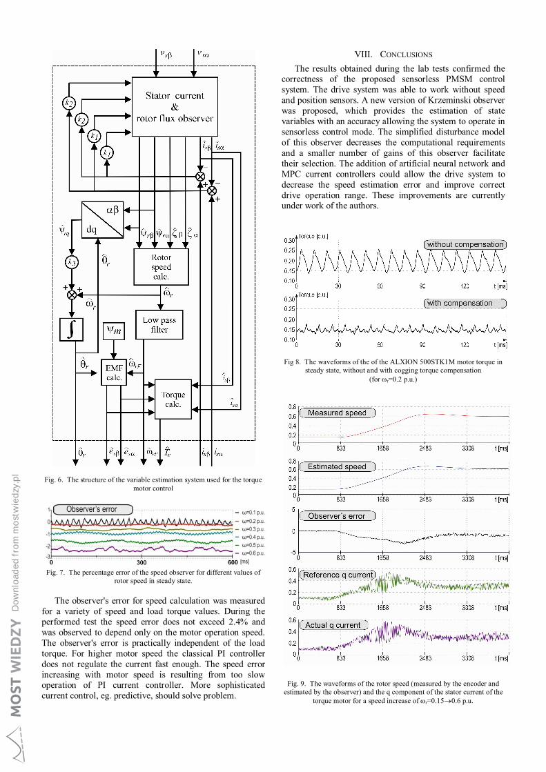
Fig. 6. The structure of the variable estimation system used for the torque motor control
Fig. 7. The percentage error of the speed observer for different values of
rotor speed in steady state.
The observer's error for speed calculation was measured for a variety of speed and load torque values. During the performed test the speed error does not exceed 2.4% and was observed to depend only on the motor operation speed. The observer's error is practically independent of the load torque. For higher motor speed the classical PI controller does not regulate the current fast enough. The speed error increasing with motor speed is resulting from too slow operation of PI current controller. More sophisticated current control, eg. predictive, should solve problem.
VIII. CONCLUSIONS The results obtained during the lab tests confirmed the
correctness of the proposed sensorless PMSM control system. The drive system was able to work without speed and position sensors. A new version of Krzeminski observer was proposed, which provides the estimation of state variables with an accuracy allowing the system to operate in sensorless control mode. The simplified disturbance model of this observer decreases the computational requirements and a smaller number of gains of this observer facilitate their selection. The addition of artificial neural network and MPC current controllers could allow the drive system to decrease the speed estimation error and improve correct drive operation range. These improvements are currently under work of the authors.
Fig 8. The waveforms of the of the ALXION 500STK1M motor torque in steady state, without and with cogging torque compensation
(for r=0.2 p.u.)
Fig. 9. The waveforms of the rotor speed (measured by the encoder and estimated by the observer) and the q component of the stator current of the
torque motor for a speed increase of r=0.150.6 p.u.
Do
wnl
oad
ed f
rom
mo
stw
ied
zy.p
l

IX. REFERENCES 1. M. Skiwski T. Tarczewski T. and L. M. Grzesiak, “PMSM drive
based on STM32F4 Microcontroller”, in Poznan University of Technology Academic Journals, no. 87, pp. 377-387, 2016.
2. D. Flieller, N. K. Nguyen, P. Wira, G. Sturtzer, D.O. Abdeslam and J. Merckle, “A Self-Learning Solution for Torque Ripple Reduction for Non-Sinusoidal Permanent Magnet Motor Drives Based on Artificial Neural Networks”, in IEEE Transactions on Industrial Electronics, vol. 61, no. 2, DOI 10.1109/TIE.2013.2257136, pp. 655–666, February 2014.
3. M. Morawiec, Z. Krzeminski and A. Lewicki, „Sterowanie silnikiem o magnesach trwałych PMSM z obserwatorem prędkości kątowej wirnika”, in Przegląd Elektrotechniczny, no. 8, pp. 48-52, 2009. (in Polish)
4. Li Yongdong and Zhu Hao, “Sensorless Control of Permanent Magnet Synchronous Motor – A Survey”, in IEEE Vehicle Power and Propulsion Conference proceedings, Harbin, China, September 3-5, 2008.
5. K. Urbanski, “A new sensorless speed control structure for PMSM using reference model”, in Bulletin of the Polish Academy of Sciences, Technical Sciences, vol. 65, no. 4, DOI: 10.1515/bpasts-2017-0054, pp. 489-496, 2017.
6. F. Benchabane, A. Titaouine, O. Bennis, K. Yahia, D. Tajbi and A. Guettaf, "Sensorless direct torque control for salient-pole PMSM based on extended Kalman filter fed by AC/DC/AC converter", in Frontiers of Energy, vol. 6, no. 3, DOI: 10.1007/s11708-012-0190-1, pp. 247-254, 2012.
7. S. Singh and A. N. Tiwari, “Various techniques of speed control of PMSM. A review”, in Second International Conference on Electrical, Computer and Communication Technologies (ICECCT) proceedings, Coimbatore, India, February 22-24, 2017, DOI: 10.1109/ICECCT.2017.8117995.
8. A. S. Mohamed, M. S. Zaky, A. Z. Zein El Din and H. A. Yasin, "Comparative Study of Sensorless Control Methods of PMSM Drives", in Innovative Systems Design and Engineering, vol. 2, no. 5, pp. 44-66, 2011.
9. J. Guziński, K. Łuksza, M. Morawiec, P. Strankowski and Z. Krzemiński, "Bezczujnikowe sterowanie wolnoobrotowym silnikiem PMSM z kompensacją momentu zaczepowego", in Scientific Bulletin of Electrical and Control Engineering Department of Gdańsk University of Technology, no 60, DOI: 10.32016/1.60.05, pp. 27-31, 2018. (in Polish)
10. J. Moravec, "Torque ripple of permanent magnet synchronous torque motor", in Studentské tvůrčí činnosti, STČ 2010.
11. Chun-Yu Hsiao, Sheng-Nian Yeh and Jonq-Chin Hwang, "A novel cogging torque simulation method for permanent-magnet synchronous machines" in Energies, vol. 4, no 12, DOI: 10.3390/en4122166, pp. 2165-2179, December 2011.
12. C. Studer, A. Keyhani, T. Sebastian and S.K. Murthy, "Study of Cogging Torque in Permanent Magnet Machines" in IAS '97.
Conference Record of the 1997 IEEE Industry Applications Conference Thirty-Second IAS Annual Meeting, New Orleans, LA, USA, 5-9 October 1997 , DOI: 10.1109/IAS.1997.643006, pp. 42-49.
13. J. Holtz and L. Springob, "Identification and compensation of torque ripple in high-precision permanent magnet motor drives", in IEEE Transactions on Industrial Electronics, vol. 43, no 2, DOI: 10.1109/41.491355, pp. 309–320, 1996.
14. S. Brock and J. Deskur, “A practical approach to compensation of torque ripple in high precision permanent magnet motor drives”, in 3th International Conference on Electrical Drives and Power Electronics proceedings, Dubrovnik, Croatia, 26-28 September 2005.
15. S. K. Panda, J. Xu and W. Qian, "Review of torque ripple minimization in PM synchronous motor drives" in 2008 IEEE Power and Energy Society General Meeting - Conversion and Delivery of Electrical Energy in the 21st Century, Pittsburgh, USA, 20-24 July 2008, DOI: 10.1109/PES.2008.4596931.
16. B. Grcar, P. Cafuta, G. Stumberger and A. M. Stanković, "Control-Based Reduction of Pulsating Torque for PMAC Machines" in IEEE Transactions on Energy Conversion, vol.17, nr 2, DOI: 10.1109/MPER.2002.4312050, pp. 169-175, June 2002.
17. N. Levin, S. Orlova, V. Pugachov, B. Ose-Zala and E. Jakobsons, “Methods to Reduce the Cogging Torque in Permanent Magnet Synchronous Machines”, in Elektronika ir Elektrotechnika, vol. 19, no. 1, DOI 10.5755/j01.eee.19.1.3248, pp. 23-26, 2013.
18. Frameless brushless motors for direct drive. Alxion STK, http://www.alxion.com/products/stk-motors/.
19. C. Ning, W. Zhihong, Y. Shouyi, G. Weihua and G. Yuqian, “A New Starting Method of Sensorless PMSM Motors Based on STM32F103B”, in 29th Chinese Control Conference proceedings, Beijing, China, July 29-31, 2010.
20. T. Yamakawa, S. Wakao, K. Kondo, T. Yoneyama, S. Taniguchi, S. Mochizuki, “Starting Procedure of Rotation Sensorless PMSM at Coasting Condition for Railway Vehicle Traction”, in Wiley Periodicals, Inc. Electrical Engineering in Japan, vol. 169, No. 2, pp. 56-63, 2009.
21. L. Wang, H. Zhang and X. Liu, "Sliding mode variable structure I/O feedback linearization design for the speed control of PMSM with load torque observer", in International Journal of Innovative Computing, Information and Control, vol. 9, no. 8, pp. 3485-3496, August 2013.
22. H. Abu-Rub, J. Guzinski and P. Strankowski, “Variable speed AC drives with inverter output filters”, Wiley, 2015.
23. Z. Krzemiński, "Obserwatory prędkości dla bezczujnikowego sterowania maszynami prądu przemiennego" in Przegląd Elektrotechniczny, vol. 90, no 5, 2014. (in Polish)
24. B. K. Bose, “Power Electronics and Variable Frequency Drives”, IEEE Press, 1997.
Do
wnl
oad
ed f
rom
mo
stw
ied
zy.p
l
Related Documents