Freescale Semiconductor Application Note Document Number: AN5014 Rev. 0, 10/2014 Contents © Freescale Semiconductor, Inc., 2014. All rights reserved. 1 Overview This application note represents an addendum to Freescale document DRM148: Sensorless PMSM Field-Oriented Control [1] 1 . It describes the MCU peripherals used in the application, the hardware setup, and the results of useful measurements for two of Freescale’s Digital Signal Controllers (DSC): MC56F82748 (see [2]) and MC56F84789 (see [3]). The MC56F82748 is derived from the higher-performance MC56F84789, so the peripherals used in the application will be identical. 2 Peripherals The present PMSM application uses only the essential peripherals for control technique implemented in the application code: • 12-bit cyclic analog-to-digital converter (ADC) 1. The numbers in square brackets refer to items listed in Appendix A, “References,” of this application note. 1 Overview . . . . . . . . . . . . . . . . . . . . . . . . . . . . . . . . . . . . . 1 2 Peripherals . . . . . . . . . . . . . . . . . . . . . . . . . . . . . . . . . . . 1 2.1 Enhanced Flex PWM (eFlexPWM) configuration . . 2 2.2 ADC configuration . . . . . . . . . . . . . . . . . . . . . . . . . . 3 2.3 ADC conversion timing, currents and voltage sam- pling . . . . . . . . . . . . . . . . . . . . . . . . . . . . . . . . . . . . . 3 2.4 Current measurement. . . . . . . . . . . . . . . . . . . . . . . 3 2.5 Overcurrent level . . . . . . . . . . . . . . . . . . . . . . . . . . . 6 2.6 SPI configuration . . . . . . . . . . . . . . . . . . . . . . . . . . . 6 2.7 SCI (UART) configuration . . . . . . . . . . . . . . . . . . . . 6 3 Interrupts . . . . . . . . . . . . . . . . . . . . . . . . . . . . . . . . . . . . . 7 3.1 ADC End of Scan interrupt . . . . . . . . . . . . . . . . . . . 7 3.2 Port interrupt . . . . . . . . . . . . . . . . . . . . . . . . . . . . . . 8 4 Application operation . . . . . . . . . . . . . . . . . . . . . . . . . . . . 8 4.1 FreeMASTER installation on the PC or notebook . . 9 4.2 Establishing a connection between the PC and the embedded application . . . . . . . . . . . . . . . . . . . . . . . 9 4.3 Application operation using FreeMASTER . . . . . . . 9 4.4 MCAT tool control . . . . . . . . . . . . . . . . . . . . . . . . . 13 5 Project file structure . . . . . . . . . . . . . . . . . . . . . . . . . . . . 14 5.1 Files in the \src folder . . . . . . . . . . . . . . . . . . . . . . 14 5.2 Files in main project folder: . . . . . . . . . . . . . . . . . . 14 6 Memory usage . . . . . . . . . . . . . . . . . . . . . . . . . . . . . . . . 15 7 Hardware setup . . . . . . . . . . . . . . . . . . . . . . . . . . . . . . . 15 7.1 Hardware set-up and jumper configuration . . . . . . 15 8 Measurement results . . . . . . . . . . . . . . . . . . . . . . . . . . . 20 8.1 CPU load and execution time . . . . . . . . . . . . . . . . 20 8.2 FreeMASTER results. . . . . . . . . . . . . . . . . . . . . . . 21 9 Conclusion . . . . . . . . . . . . . . . . . . . . . . . . . . . . . . . . . . . 22 Appendix A References . . . . . . . . . . . . . . . . . . . . . . . . . . . . . 22 Three-Phase PMSM Sensorless FOC using MC56F82748 and MC56F84789 with Automated Motor Parameter Identification by Pavel Sustek

Welcome message from author
This document is posted to help you gain knowledge. Please leave a comment to let me know what you think about it! Share it to your friends and learn new things together.
Transcript
Freescale SemiconductorApplication Note
Document Number: AN5014Rev. 0, 10/2014
Contents
Overview . . . . . . . . . . . . . . . . . . . . . . . . . . . . . . . . . . . . . 1Peripherals . . . . . . . . . . . . . . . . . . . . . . . . . . . . . . . . . . . 1
2.1 Enhanced Flex PWM (eFlexPWM) configuration . . 22.2 ADC configuration . . . . . . . . . . . . . . . . . . . . . . . . . . 32.3 ADC conversion timing, currents and voltage sam-
pling. . . . . . . . . . . . . . . . . . . . . . . . . . . . . . . . . . . . . 32.4 Current measurement. . . . . . . . . . . . . . . . . . . . . . . 32.5 Overcurrent level . . . . . . . . . . . . . . . . . . . . . . . . . . . 62.6 SPI configuration . . . . . . . . . . . . . . . . . . . . . . . . . . . 62.7 SCI (UART) configuration . . . . . . . . . . . . . . . . . . . . 6Interrupts . . . . . . . . . . . . . . . . . . . . . . . . . . . . . . . . . . . . . 7
3.1 ADC End of Scan interrupt . . . . . . . . . . . . . . . . . . . 73.2 Port interrupt . . . . . . . . . . . . . . . . . . . . . . . . . . . . . . 8Application operation . . . . . . . . . . . . . . . . . . . . . . . . . . . . 8
4.1 FreeMASTER installation on the PC or notebook . . 94.2 Establishing a connection between the PC and the
embedded application . . . . . . . . . . . . . . . . . . . . . . . 94.3 Application operation using FreeMASTER . . . . . . . 94.4 MCAT tool control . . . . . . . . . . . . . . . . . . . . . . . . . 13Project file structure. . . . . . . . . . . . . . . . . . . . . . . . . . . . 14
5.1 Files in the \src folder . . . . . . . . . . . . . . . . . . . . . . 145.2 Files in main project folder: . . . . . . . . . . . . . . . . . . 14Memory usage. . . . . . . . . . . . . . . . . . . . . . . . . . . . . . . . 15Hardware setup . . . . . . . . . . . . . . . . . . . . . . . . . . . . . . . 15
7.1 Hardware set-up and jumper configuration . . . . . . 15Measurement results . . . . . . . . . . . . . . . . . . . . . . . . . . . 20
8.1 CPU load and execution time . . . . . . . . . . . . . . . . 208.2 FreeMASTER results. . . . . . . . . . . . . . . . . . . . . . . 21Conclusion. . . . . . . . . . . . . . . . . . . . . . . . . . . . . . . . . . . 22
ppendix A References. . . . . . . . . . . . . . . . . . . . . . . . . . . . . 22
Three-Phase PMSM Sensorless FOC using MC56F82748 and MC56F84789 with Automated Motor Parameter Identificationby Pavel Sustek
1 OverviewThis application note represents an addendum to Freescale document DRM148: Sensorless PMSM Field-Oriented Control [1]1. It describes the MCU peripherals used in the application, the hardware setup, and the results of useful measurements for two of Freescale’s Digital Signal Controllers (DSC): MC56F82748 (see [2]) and MC56F84789 (see [3]). The MC56F82748 is derived from the higher-performance MC56F84789, so the peripherals used in the application will be identical.
2 PeripheralsThe present PMSM application uses only the essential peripherals for control technique implemented in the application code:
• 12-bit cyclic analog-to-digital converter (ADC)
1. The numbers in square brackets refer to items listed in Appendix A, “References,” of this application note.
12
3
4
5
67
8
9A
© Freescale Semiconductor, Inc., 2014. All rights reserved.
Peripherals
• eFlex pulse-width modulation (PWM)
• XBAR
• Serial peripheral interface (SPI)
• Serial communication interface (SCI)
Other peripherals are disabled. A peripheral initialization is done using the Freescale QuickStart tool (see [4]) which offers a simple-to-use interface for all device peripheral settings. Detailed descriptions of the peripherals used are in the following sections.
2.1 Enhanced Flex PWM (eFlexPWM) configuration
The eFlexPWM module is a dedicated peripheral enabling the generation of three-phase PWM signals connected to MOSFET H-bridge via MC33937 pre-driver. The three PWM submodules used in the application are configured using the Graphical Configuration Tool (GCT) as listed here:
• PWM_0
— IPBus clock source 100 MHz
— Running frequency of 10 kHz with 100 s period
— INIT register –5000, VAL1 4999 — 13-bit resolution
— Complementary mode with 0.5 s dead time
— PWM reload and synchronization signals generated every opportunity from this module
— Trigger 4 enabled to provide synchronization with ADC module via XBAR
— High-side switch PWM_A output in negative (active low) polarity
— Low-side switch PWM_B output in positive (active high) polarity
• PWM_1 and PWM_2
— PWM_0 clock source
— Running frequency of 10 kHz with 100 s period
— INIT register –5000, VAL1 4999 — 13-bit resolution
— Complementary mode with 0.5 s dead time
— PWM reload and synchronization signals generated every opportunity from this module
— High-side switch PWM_A output in negative (active low) polarity
— Low-side switch PWM_B output in positive (active high) polarity
• PWM FAULT
— Fault 0 signal with high-level detection connected via XBAR input from over-current MC33937 driver output
— Automatic fault clearing
— PWM_A, PWM1_A, and PWM2_A channels disabled and output pins set to high-level if a fault is detected
— PWM0_B, PWM1_B, and PWM2_B channels disabled and output pins set to low-level if a fault is detected
— Fault input filter disabled
Three-Phase PMSM Sensorless FOC using MC56F82748 and MC56F84789 with Automated Motor Parameter Identification, Rev. 0
Freescale Semiconductor2
Peripherals
2.2 ADC configuration
The on-chip ADC module is used to sample feedback signals (motor phase currents and DC bus voltage) that are necessary to successfully perform the vector control algorithm. The eFlexPWM serves the Trigger 4 signal via XBAR for the hardware triggering of both ADCs in parallel mode.
The ADC module clock is set to maximum frequency, 10 MHz for the MC56F82748 and 20 MHz for the MC56F84789.
2.3 ADC conversion timing, currents and voltage sampling
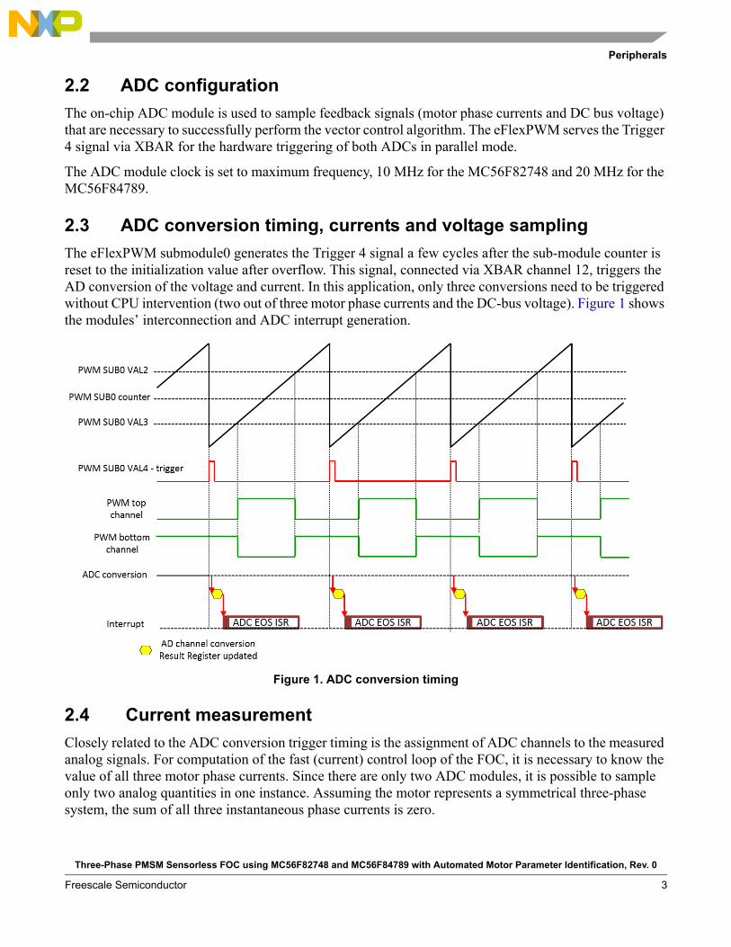
The eFlexPWM submodule0 generates the Trigger 4 signal a few cycles after the sub-module counter is reset to the initialization value after overflow. This signal, connected via XBAR channel 12, triggers the AD conversion of the voltage and current. In this application, only three conversions need to be triggered without CPU intervention (two out of three motor phase currents and the DC-bus voltage). Figure 1 shows the modules’ interconnection and ADC interrupt generation.
Figure 1. ADC conversion timing
2.4 Current measurement
Closely related to the ADC conversion trigger timing is the assignment of ADC channels to the measured analog signals. For computation of the fast (current) control loop of the FOC, it is necessary to know the value of all three motor phase currents. Since there are only two ADC modules, it is possible to sample only two analog quantities in one instance. Assuming the motor represents a symmetrical three-phase system, the sum of all three instantaneous phase currents is zero.
Three-Phase PMSM Sensorless FOC using MC56F82748 and MC56F84789 with Automated Motor Parameter Identification, Rev. 0
Freescale Semiconductor 3

Peripherals
0 = iA + iB + iC Eqn. 1
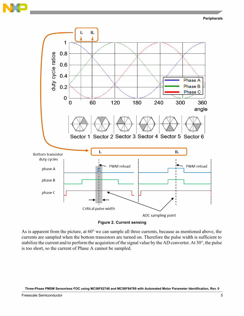
Since the phase currents are measured when the bottom transistors are conducting, in the case of high duty cycle ratios (current value is in the area of the maximum of the sine curve), the time when the current can be measured is too short. The bottom transistor must be switched on for at least a critical pulse width to get a stabilized current shunt resistor voltage drop.
The selection of the channels is done based on the section where the space vector of the stator current is generated. This assignment is performed at the end of the ADC End of Scan interrupt service routine. Therefore, it is enough to sample only two phase currents while the third is easily calculated according to Equation 2.
Sector 1,6: iA = - iB - iCSector 2,3: iB = - iA - iCSector 4,5: iC = - iB - iA
Eqn. 2
Figure 2 shows two instances of the electrical period (case I at 60°, case II at 30°) indicating why the calculation of the third current is necessary.
Three-Phase PMSM Sensorless FOC using MC56F82748 and MC56F84789 with Automated Motor Parameter Identification, Rev. 0
Freescale Semiconductor4
Peripherals
Figure 2. Current sensing
As is apparent from the picture, at 60° we can sample all three currents, because as mentioned above, the currents are sampled when the bottom transistors are turned on. Therefore the pulse width is sufficient to stabilize the current and to perform the acquistion of the signal value by the AD converter. At 30°, the pulse is too short, so the current of Phase A cannot be sampled.
Three-Phase PMSM Sensorless FOC using MC56F82748 and MC56F84789 with Automated Motor Parameter Identification, Rev. 0
Freescale Semiconductor 5
Peripherals
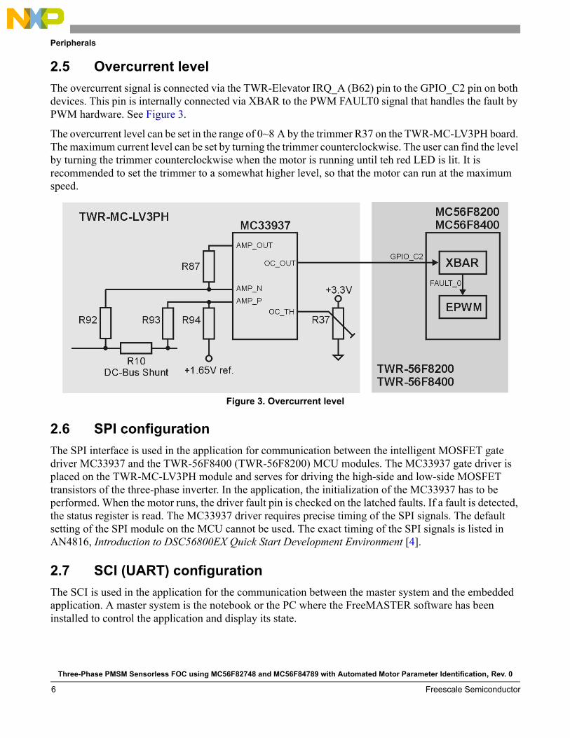
2.5 Overcurrent level
The overcurrent signal is connected via the TWR-Elevator IRQ_A (B62) pin to the GPIO_C2 pin on both devices. This pin is internally connected via XBAR to the PWM FAULT0 signal that handles the fault by PWM hardware. See Figure 3.
The overcurrent level can be set in the range of 0~8 A by the trimmer R37 on the TWR-MC-LV3PH board. The maximum current level can be set by turning the trimmer counterclockwise. The user can find the level by turning the trimmer counterclockwise when the motor is running until teh red LED is lit. It is recommended to set the trimmer to a somewhat higher level, so that the motor can run at the maximum speed.
Figure 3. Overcurrent level
2.6 SPI configuration
The SPI interface is used in the application for communication between the intelligent MOSFET gate driver MC33937 and the TWR-56F8400 (TWR-56F8200) MCU modules. The MC33937 gate driver is placed on the TWR-MC-LV3PH module and serves for driving the high-side and low-side MOSFET transistors of the three-phase inverter. In the application, the initialization of the MC33937 has to be performed. When the motor runs, the driver fault pin is checked on the latched faults. If a fault is detected, the status register is read. The MC33937 driver requires precise timing of the SPI signals. The default setting of the SPI module on the MCU cannot be used. The exact timing of the SPI signals is listed in AN4816, Introduction to DSC56800EX Quick Start Development Environment [4].
2.7 SCI (UART) configuration
The SCI is used in the application for the communication between the master system and the embedded application. A master system is the notebook or the PC where the FreeMASTER software has been installed to control the application and display its state.
Three-Phase PMSM Sensorless FOC using MC56F82748 and MC56F84789 with Automated Motor Parameter Identification, Rev. 0
Freescale Semiconductor6
Interrupts
On both DSC devices two UART modules are implemented. Due to the hardware solution being based on the Tower modules, UART1 is used. The communication speed is set to 19200 Bd.
3 InterruptsBecause it is possible for the MCU to initiate hardware triggering of the AD conversion, the application requires the minimum number of interrupts.
3.1 ADC End of Scan interrupt
This interrupt request is triggered when the channel conversion is completed. It has the highest priority.
During interrupt generation, sampled values of physical quantities are available in:
• Result register 0 (motor phase current 1)
• Result register 8 (motor phase current 2)
• Result register 9 (DC bus voltage)
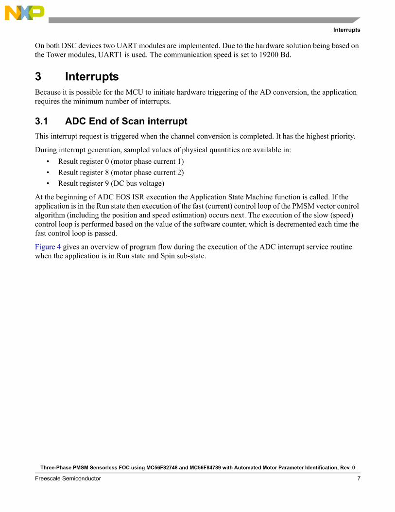
At the beginning of ADC EOS ISR execution the Application State Machine function is called. If the application is in the Run state then execution of the fast (current) control loop of the PMSM vector control algorithm (including the position and speed estimation) occurs next. The execution of the slow (speed) control loop is performed based on the value of the software counter, which is decremented each time the fast control loop is passed.
Figure 4 gives an overview of program flow during the execution of the ADC interrupt service routine when the application is in Run state and Spin sub-state.
Three-Phase PMSM Sensorless FOC using MC56F82748 and MC56F84789 with Automated Motor Parameter Identification, Rev. 0
Freescale Semiconductor 7
Application operation
Figure 4. ADC ISR flowchart
3.2 Port interrupt
Handling of the user’s buttons on the TWR-56F8400 (TWR-56F8200) board is performed in the ISR associated with the Port interrupt, generated whenever one of the buttons is pressed. At the beginning of the ISR, simple logic is executed to evaluate which button was pressed, and the interrupt flag is cleared.
The first press of the SW1 button causes the application switch from STOP to RUN mode. Consequent pressing of the SW1 button increases the speed in 10% steps of nominal speed. Pressing the SW2 button causes the speed to decrease in 10% steps and also transition back to STOP state.
4 Application operationThe application can be operated either via the user buttons on the TWR-56F8400 (TWR-56F8200) board (as mentioned in Section 3.2, “Port interrupt”) or via the FreeMASTER software, which also allows display of the application variables. The FreeMASTER application consists of two parts, the PC application used for variable display, and the set of software drivers running in the embedded application. The data is passed between the PC and the embedded application via the RS-232 interface.
Three-Phase PMSM Sensorless FOC using MC56F82748 and MC56F84789 with Automated Motor Parameter Identification, Rev. 0
Freescale Semiconductor8

Application operation
4.1 FreeMASTER installation on the PC or notebook
The FreeMASTER PC application can be downloaded from the Freescale website at “FreeMASTER Run-Time Debugging Tool.” From the “Downloads” tab, select “FreeMASTER 1.4 Application Installation.”
Because downloading the FreeMASTER application requires registration, it is necessary to create an account before you can log in. After you log into the system, the license agreement appears. You should read the license agreement and then you have to accept the agreement by clicking the “I Accept” button. If you are using Internet Explorer, then at the top of the web page you will see a bar asking to authorize the file download. Click on the bar and select “Download File”. A dialog box appears where you can choose to either Run or Save. In both cases, the installation archive will be stored on your machine. By selecting “Save,” you have the option to select your preferred location for saving the installation archive, otherwise it will be saved to a Temporary folder created by your system. The library installation archive will be now downloaded to your computer.
To run the installation, click the “Run” button. Follow the instructions on the screen to complete the installation process.
4.2 Establishing a connection between the PC and the embedded application
Using FreeMASTER allows the use of multiple communication interfaces between the embedded application and the PC or notebook (UART (RS-232), CAN, Ethernet, USB, BDM, etc.). For this application, the RS-232 was used because the software overhead for the data transfer represents the lowest additional load on the CPU. Nowadays, notebooks are not equipped with a COM port, so for this purpose the TWR-56F8400 (TWR-56F8200) module has in place a USB-to-RS-232 interface (CDC Serial Port). By connecting the TWR-56F8400 (TWR-56F8200) module with a notebook via the USB cable, a virtual serial port will be established in the Windows system.
4.3 Application operation using FreeMASTER
To run the FreeMASTER application, double click on the PMSM_FOC_MC56F84789.pmp (PMSM_FOC_MC56F82748.pmp) file located in the \freemaster\PMSM_Sensorless_FOC_MID folder. The FreeMASTER application starts and the environment will be automatically created, as it is defined in the *.pmp file.
4.3.1 Setting up communication
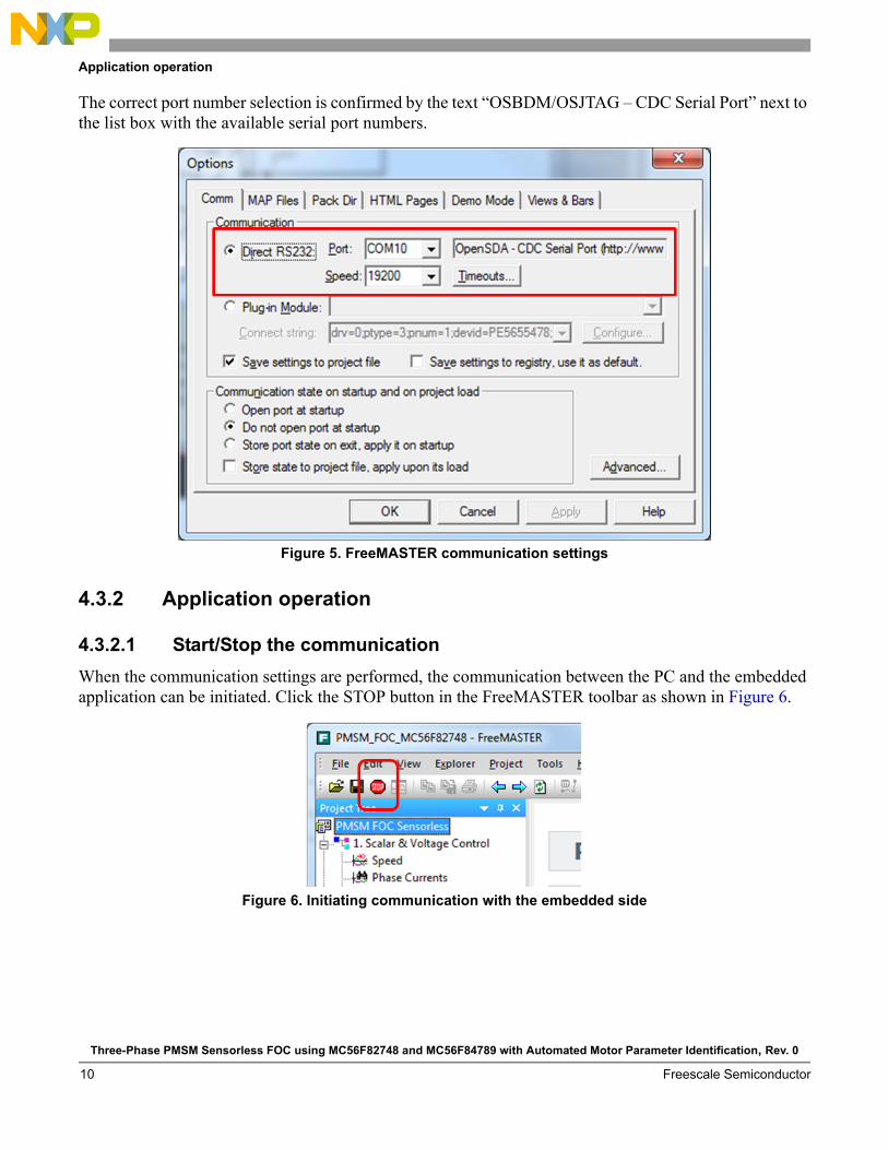
When the notebook is connected via USB cable with the TWR-56F8400 (TWR-56F8200) board, the operating system assigns the number of the COM port to the OSBDM/OSJTAG CDC Serial Port. This number is assigned randomly — therefore it is necessary to set the right communication port each time the connection is established (re-plugging the USB cable might cause a different port number assignment).
To set the port number, click the menu item Project \ Options …
Then assign the port number in the “Comm” tab of the opened window.
Three-Phase PMSM Sensorless FOC using MC56F82748 and MC56F84789 with Automated Motor Parameter Identification, Rev. 0
Freescale Semiconductor 9
Application operation
The correct port number selection is confirmed by the text “OSBDM/OSJTAG – CDC Serial Port” next to the list box with the available serial port numbers.
Figure 5. FreeMASTER communication settings
4.3.2 Application operation
4.3.2.1 Start/Stop the communication
When the communication settings are performed, the communication between the PC and the embedded application can be initiated. Click the STOP button in the FreeMASTER toolbar as shown in Figure 6.
Figure 6. Initiating communication with the embedded side
Three-Phase PMSM Sensorless FOC using MC56F82748 and MC56F84789 with Automated Motor Parameter Identification, Rev. 0
Freescale Semiconductor10
Application operation
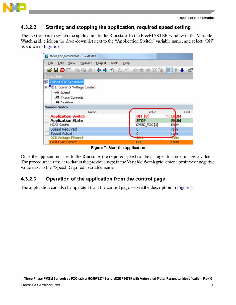
4.3.2.2 Starting and stopping the application, required speed setting
The next step is to switch the application to the Run state. In the FreeMASTER window in the Variable Watch grid, click on the drop-down list next to the “Application Switch” variable name, and select “ON” as shown in Figure 7.
Figure 7. Start the application
Once the application is set to the Run state, the required speed can be changed to some non-zero value. The procedure is similar to that in the previous step; in the Variable Watch grid, enter a positive or negative value next to the “Speed Required” variable name.
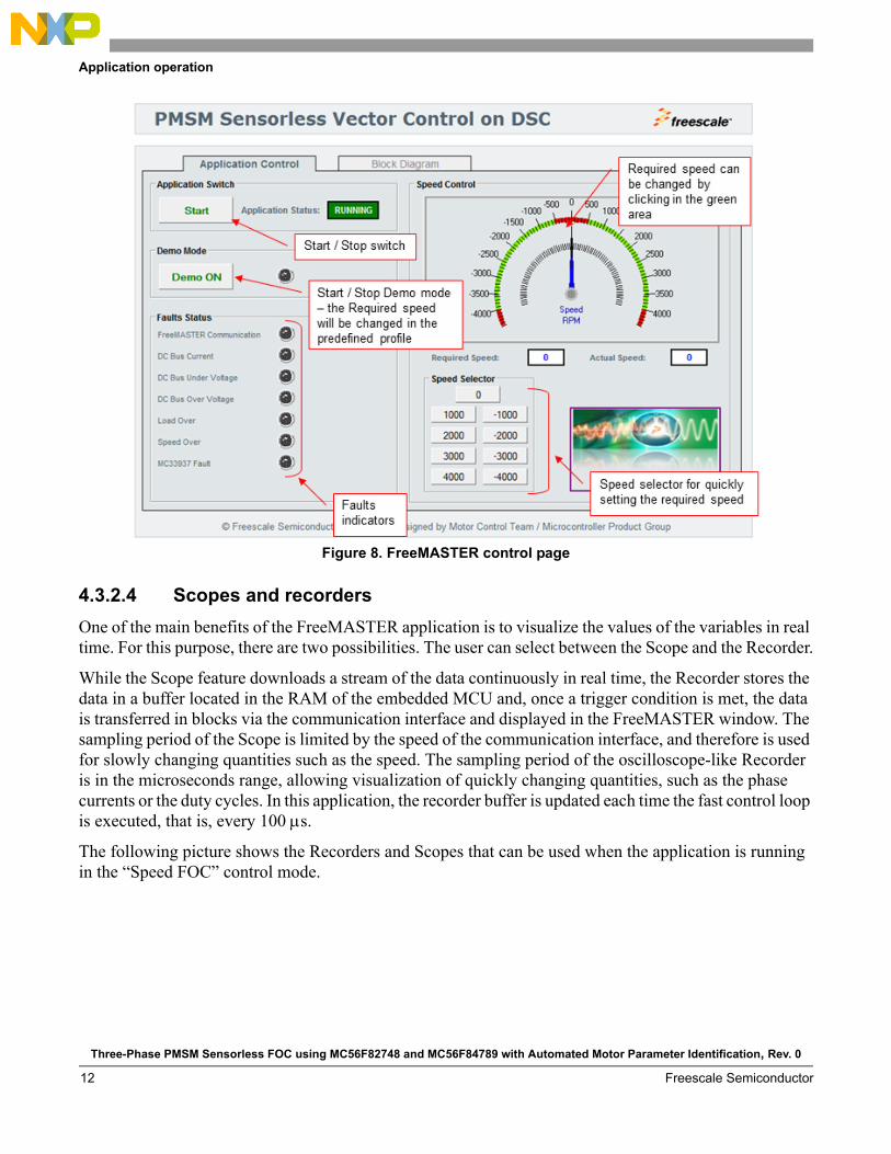
4.3.2.3 Operation of the application from the control page
The application can also be operated from the control page — see the description in Figure 8.
Three-Phase PMSM Sensorless FOC using MC56F82748 and MC56F84789 with Automated Motor Parameter Identification, Rev. 0
Freescale Semiconductor 11
Application operation
Figure 8. FreeMASTER control page
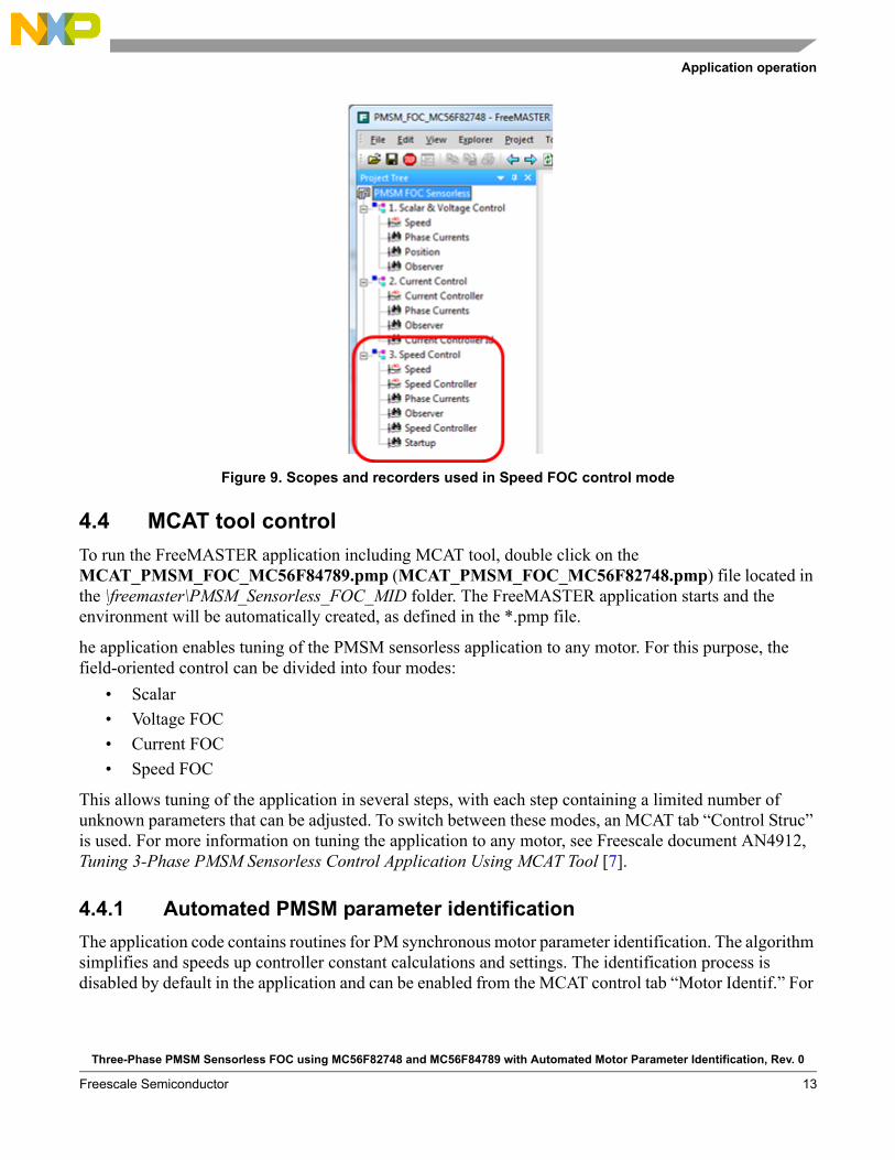
4.3.2.4 Scopes and recorders
One of the main benefits of the FreeMASTER application is to visualize the values of the variables in real time. For this purpose, there are two possibilities. The user can select between the Scope and the Recorder.
While the Scope feature downloads a stream of the data continuously in real time, the Recorder stores the data in a buffer located in the RAM of the embedded MCU and, once a trigger condition is met, the data is transferred in blocks via the communication interface and displayed in the FreeMASTER window. The sampling period of the Scope is limited by the speed of the communication interface, and therefore is used for slowly changing quantities such as the speed. The sampling period of the oscilloscope-like Recorder is in the microseconds range, allowing visualization of quickly changing quantities, such as the phase currents or the duty cycles. In this application, the recorder buffer is updated each time the fast control loop is executed, that is, every 100 s.
The following picture shows the Recorders and Scopes that can be used when the application is running in the “Speed FOC” control mode.
Three-Phase PMSM Sensorless FOC using MC56F82748 and MC56F84789 with Automated Motor Parameter Identification, Rev. 0
Freescale Semiconductor12
Application operation
Figure 9. Scopes and recorders used in Speed FOC control mode
4.4 MCAT tool control
To run the FreeMASTER application including MCAT tool, double click on the MCAT_PMSM_FOC_MC56F84789.pmp (MCAT_PMSM_FOC_MC56F82748.pmp) file located in the \freemaster\PMSM_Sensorless_FOC_MID folder. The FreeMASTER application starts and the environment will be automatically created, as defined in the *.pmp file.
he application enables tuning of the PMSM sensorless application to any motor. For this purpose, the field-oriented control can be divided into four modes:
• Scalar
• Voltage FOC
• Current FOC
• Speed FOC
This allows tuning of the application in several steps, with each step containing a limited number of unknown parameters that can be adjusted. To switch between these modes, an MCAT tab “Control Struc” is used. For more information on tuning the application to any motor, see Freescale document AN4912, Tuning 3-Phase PMSM Sensorless Control Application Using MCAT Tool [7].
4.4.1 Automated PMSM parameter identification
The application code contains routines for PM synchronous motor parameter identification. The algorithm simplifies and speeds up controller constant calculations and settings. The identification process is disabled by default in the application and can be enabled from the MCAT control tab “Motor Identif.” For
Three-Phase PMSM Sensorless FOC using MC56F82748 and MC56F84789 with Automated Motor Parameter Identification, Rev. 0
Freescale Semiconductor 13

Project file structure
more information on user motor identification, see Freescale document AN4986, Automated PMSM Parameter Identification [9].
5 Project file structureThe total number of source (*.c) and header files (*.h) in the project exceeds one hundred. Therefore, only the key project files will be described in detail, and the rest will be described in groups.
The main project folder is divided into seven directories:
• \FLASH_SDM — contains compiler’s output executable and object files
• \SAC folder (Sensor and Actuator Components) contains routines for accessing peripherals used by motor control algorithm to sense input feedback physical quantities (currents, voltage, speed, position) and to set the actuators based on calculated output variables (FlexTimer, MOSFET pre-driver)
• freemaster\PMSM_Sensorless_FOC_MID — contains the FreeMASTER configuration files and supporting files (control page in HTML format and the binary file with addresses of the variables)
• \src — contains QuickStart folders and the project source and header files — its contents are described below
• \FSLESL folder (Freescale Embedded Software Libraries) contains a set of functions used in control algorithms
• \ApplicationConfig contains the appconfig.h file that is the output file of the Graphical Configuration Tool (GCT), storing the actual MCU peripheral configuration
• \MID_codebase contains motor identification routine source codes
5.1 Files in the \src folder• M1_statemachine.c and M1_statemachine.h contain the software routines executed when the
application is in a particular state or state transition
• State_machine.c and state_machine.h contain the application state machine structure definition and manage switching between the application states and application state transitions
• Motor_structure.c and motor_structure.h contain the structure definitions and subroutines dedicated for execution of the motor control algorithm (vector control algorithm, position and speed estimation algorithm, speed control loop)
• Motor_def.h contains the main control and fault structure definition
5.2 Files in main project folder:
main.c contains basic application initialization (enabling interrupts), subroutines accessing the MCU peripherals, and interrupt service routines. In the background infinite loop FreeMASTER communication is performed.
PMSMFOC_appconfig.h contains definitions of constants for the application control processes (parameters of the motor and regulators and constants for other vector-control-related algorithms). When
Three-Phase PMSM Sensorless FOC using MC56F82748 and MC56F84789 with Automated Motor Parameter Identification, Rev. 0
Freescale Semiconductor14
Memory usage
the application is tailored for another motor using the Motor Control Application Tuning (MCAT) tool, this file is generated by the tool at the end of the tuning process.
6 Memory usageTable 1 summarizes chip memory usage.
Table 2 summarizes chip memory usage for selected algorithm blocks. Both DSC devices have the same core so the code size is listed together.
7 Hardware setupThe Tower modular development system is used as the hardware platform for the PMSM sensorless application on the MC56F84789 and MC56F82748. It consists of these modules:
• Tower elevator modules (TWR-ELEV)
• DSC tower module (TWR-56F8400 or TWR-56F8200)
• Three-phase low-voltage power module (TWR-MC-LV3PH) with included motor
All modules of the Tower system are available for order via the Freescale web page or from distributors, so the user can easily build the hardware platform for which the application is targeted.
7.1 Hardware set-up and jumper configuration
Building the system using the modules of the Tower system is not difficult. The peripheral modules and the MCU module are plugged into the elevator connectors, while the white stripe on the side of the module
Table 1. Total memory usage
Memory Total / Used on MC56F84789 Total / Used on MC56F82748
Program flash (application code) 256 KB / 20 KB 64 KB / 20 KB
Data flash (application constants) 200 Bytes 200 Bytes
Data RAM (application variables) 6,494 Bytes1
1 Includes 4 KB FreeMASTER buffer.
4,298 Bytes2
2 Includes 2 KB FreeMASTER buffer.
Table 2. Algorithm blocks memory usage
Algorithm blockProgram memory (code + constants)
[ Bytes ]
Data memory[ Bytes ]
FOC (fast + slow loops) 2,274 154
FreeMASTER 2,732 2,218
SAC (Sensor and Actuator Components) 4,658 168
MID (Motor Identification) 3,490 634
Application state machine 4,490 894
Three-Phase PMSM Sensorless FOC using MC56F82748 and MC56F84789 with Automated Motor Parameter Identification, Rev. 0
Freescale Semiconductor 15

Hardware setup
boards determines the orientation to the functional elevator (the elevator with the mini-USB connector, power supplies, and switch).
It is necessary to configure jumpers on the tower modules.
The jumper settings for the TWR-56F8400 and TWR-56F8200 boards are listed in Table 3.
Table 3. Jumper settings for TWR-56F8400 and TWR-56F8200 boards
Jumper Setting Jumper Setting
J1 open J11 2–3
J2 open J15 open
J4 2–3 J16 open
J5 2–3 J17 open
J7 2–3 J19 open
J8 3–4 J20 open
J9 3–4 J23 open
Three-Phase PMSM Sensorless FOC using MC56F82748 and MC56F84789 with Automated Motor Parameter Identification, Rev. 0
Freescale Semiconductor16
Hardware setup
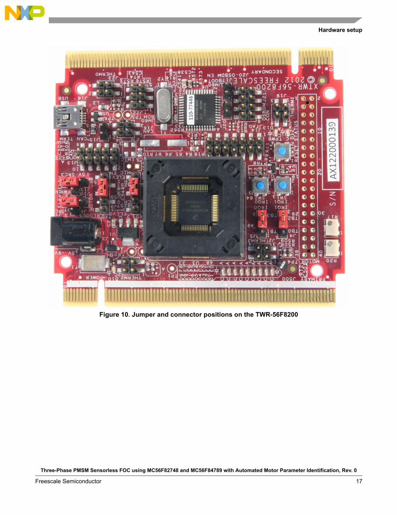
Figure 10. Jumper and connector positions on the TWR-56F8200
Three-Phase PMSM Sensorless FOC using MC56F82748 and MC56F84789 with Automated Motor Parameter Identification, Rev. 0
Freescale Semiconductor 17
Hardware setup
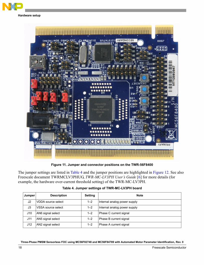
Figure 11. Jumper and connector positions on the TWR-56F8400
The jumper settings are listed in Table 4 and the jumper positions are highlighted in Figure 12. See also Freescale document TWRMCLV3PHUG, TWR-MC-LV3PH User’s Guide [6] for more details (for example, the hardware over-current threshold setting) of the TWR-MC-LV3PH.
Table 4. Jumper settings of TWR-MC-LV3PH board
Jumper Description Setting Note
J2 VDDA source select 1–2 Internal analog power supply
J3 VSSA source select 1–2 Internal analog power supply
J10 AN6 signal select 1–2 Phase C current signal
J11 AN5 signal select 1–2 Phase B current signal
J12 AN2 signal select 1–2 Phase A current signal
Three-Phase PMSM Sensorless FOC using MC56F82748 and MC56F84789 with Automated Motor Parameter Identification, Rev. 0
Freescale Semiconductor18
Hardware setup
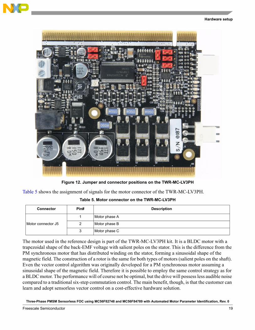
Figure 12. Jumper and connector positions on the TWR-MC-LV3PH
Table 5 shows the assignment of signals for the motor connector of the TWR-MC-LV3PH.
The motor used in the reference design is part of the TWR-MC-LV3PH kit. It is a BLDC motor with a trapezoidal shape of the back-EMF voltage with salient poles on the stator. This is the difference from the PM synchronous motor that has distributed winding on the stator, forming a sinusoidal shape of the magnetic field. The construction of a rotor is the same for both types of motors (salient poles on the shaft). Even the vector control algorithm was originally developed for a PM synchronous motor assuming a sinusoidal shape of the magnetic field. Therefore it is possible to employ the same control strategy as for a BLDC motor. The performance will of course not be optimal, but the drive will possess less audible noise compared to a traditional six-step commutation control. The main benefit, though, is that the customer can learn and adopt sensorless vector control on a cost-effective hardware solution.
Table 5. Motor connector on the TWR-MC-LV3PH
Connector Pin# Description
Motor connector J5
1 Motor phase A
2 Motor phase B
3 Motor phase C
Three-Phase PMSM Sensorless FOC using MC56F82748 and MC56F84789 with Automated Motor Parameter Identification, Rev. 0
Freescale Semiconductor 19

Measurement results
Here are the motor specifications.
NOTE
The application parameters (speed PI controller and value of the startup current) are set for a motor that has a plastic circle (part of the kit) mounted on the shaft. Otherwise, speed oscillation might occur.
8 Measurement results
8.1 CPU load and execution time
The CPU load is influenced mainly by the execution of the ADC_EOS_isr, in which the execution of the application state machine and calculation of the fast (current) and slow (speed) control loops of the PMSM vector control are performed.
Table 7 shows the machine cycle number measured from the ADC_EOS_isr routine (excluding FreeMASTER recorder function) for the worst case of Run state—a transition from open-loop startup to closed-loop speed control.
The ADC interrupt is generated periodically with the same frequency as the PWM reload event, when the values of the duty cycles are updated.
In this application, the ADC ISR is generated once per 100 s, which corresponds to 10 kHz of the PWM frequency. At 50 MHz on the DSC MC56F82748 device, it consumes 56.7% of CPU performance. At 100 MHz on the DSC MC56F84789 device, it consumes 32.3% of CPU performance.
Table 6. Specification of the motor
Motor specification
Manufacturer name Linix
Type 45ZWN24-40
Nominal voltage (line-to-line) 24 V DC
Nominal speed 4000 rpm
Rated power 40 W
Motor model parameters
Stator winding resistance(line-to-line)
1
Stator winding inductanced axis
367 H
Stator winding inductance q axis
413 H
Number of pole-pairs 2
Back-EMF constant ke 0.0136 V.s.rad–1
Three-Phase PMSM Sensorless FOC using MC56F82748 and MC56F84789 with Automated Motor Parameter Identification, Rev. 0
Freescale Semiconductor20
Measurement results
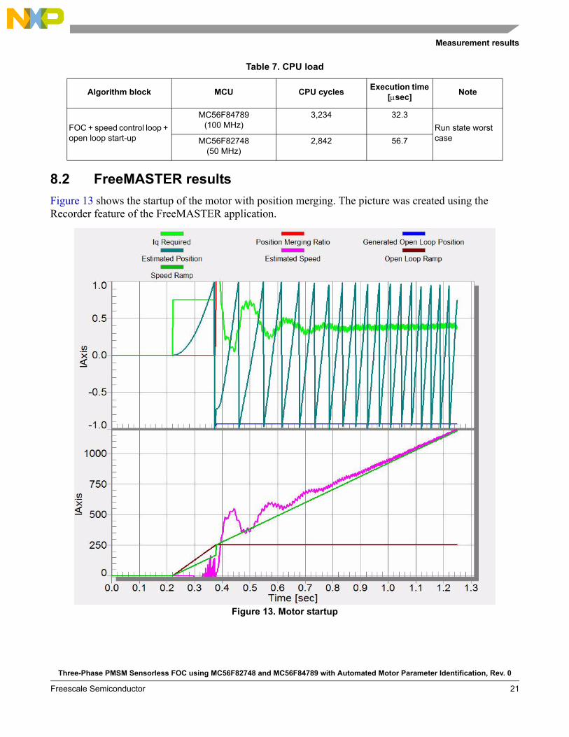
8.2 FreeMASTER results
Figure 13 shows the startup of the motor with position merging. The picture was created using the Recorder feature of the FreeMASTER application.
Figure 13. Motor startup
Table 7. CPU load
Algorithm block MCU CPU cyclesExecution time
[sec]Note
FOC + speed control loop + open loop start-up
MC56F84789(100 MHz)
3,234 32.3
Run state worst caseMC56F82748
(50 MHz)2,842 56.7
Three-Phase PMSM Sensorless FOC using MC56F82748 and MC56F84789 with Automated Motor Parameter Identification, Rev. 0
Freescale Semiconductor 21

Conclusion
9 ConclusionThe results of the execution time measurement show that the DSC MC56F84789 and MC56F82748 microcontrollers can be used to drive the PMSM sensorless vector control algorithm for high dynamic applications. The CPU load at 10 kHz PWM frequency represents 56% for MC56F82478 and only 32% for MC56F84789, so there is much room to either to increase the frequency of the fast control loop or to perform additional user tasks.
Appendix A ReferencesAll of these documents are available at freescale.com.
1. DRM148, Sensorless PMSM Field-Oriented Control
2. MC56F827XXRM, MC56F827xx Reference Manual
3. MC56F847XXRM, MC56F847XX Reference Manual
4. AN4816, Introduction to DSC56800EX Quick Start Development Environment
5. MC33937, Three Phase Field Effect Transistor Pre-driver
6. TWRMCLV3PHUG, TWR-MC-LV3PH User’s Guide
7. AN4912, Tuning 3-Phase PMSM Sensorless Control Application Using MCAT Tool
8. AN4675, Using eFlexPWM Module for ADC Synchronization in MC56F82xx and MC56F84xx Family of Digital Signal Controllers
9. AN4986, Automated PMSM Parameter Identification
Three-Phase PMSM Sensorless FOC using MC56F82748 and MC56F84789 with Automated Motor Parameter Identification, Rev. 0
Freescale Semiconductor22

Document Number: AN5014Rev. 0
10/2014
How to Reach Us:
Home Page:freescale.com
Web Support:freescale.com/support
Information in this document is provided solely to enable system and software
implementers to use Freescale products. There are no express or implied copyright
licenses granted hereunder to design or fabricate any integrated circuits based on the
information in this document.
Freescale reserves the right to make changes without further notice to any products
herein. Freescale makes no warranty, representation, or guarantee regarding the
suitability of its products for any particular purpose, nor does Freescale assume any
liability arising out of the application or use of any product or circuit, and specifically
disclaims any and all liability, including without limitation consequential or incidental
damages. “Typical” parameters that may be provided in Freescale data sheets and/or
specifications can and do vary in different applications, and actual performance may
vary over time. All operating parameters, including “typicals,” must be validated for each
customer application by customer’s technical experts. Freescale does not convey any
license under its patent rights nor the rights of others. Freescale sells products pursuant
to standard terms and conditions of sale, which can be found at the following address:
freescale.com/SalesTermsandConditions.
Freescale and the Freescale logo are trademarks of Freescale Semiconductor, Inc.,
Reg. U.S. Pat. & Tm. Off. Tower is a trademark of Freescale Semiconductor, Inc. All
other product or service names are the property of their respective owners.
© 2014 Freescale Semiconductor, Inc.
Related Documents