Experimental Implementation and Investigation of Real-Time Metrology for Exposure Controlled Projection Lithography Xiayun Zhao, Jenny M. Wang, Changxuan Zhao, Amit Jariwala, David W. Rosen* George W. Woodruff School of Mechanical Engineering Georgia Institute of Technology Atlanta, Georgia, 30332 *Corresponding author. Tel.: +1 404 894 9668 Email: [email protected] Abstract Exposure Controlled Projection Lithography (ECPL) is a stereolithography based process, curing photopolymer parts on a stationary substrate. To improve the process accuracy with closed-loop control, an in-situ interferometric curing monitoring and measurement (ICM&M) system was developed to infer the output of cured height. The previously reported ICM&M method incorporated a sensor model and online parameter estimation algorithms based on instantaneous frequency. In this paper, to validate the ICM&M method, an application program was created in MATLAB to integrate the ECPL and ICM&M systems and to acquire and analyze interferograms online. Given the limited computing power, the interferogram analysis is performed offline. Experiments were performed curing square samples by varying exposure time and intensity. They show that the ICM&M can provide a cost-effective metrology for cured heights with excellent accuracy and reliability, and decent capability of estimating lateral dimensions. The offline ICM&M is a convincing demonstration and benchmark for the real-time ICM&M metrology. 1. Introduction Lack of in-situ sensors and measurement methods for in-situ process control is identified as high priority research and development activities for overcoming the barriers in improving the quality and repeatability of additive manufacturing (AM) processes [1]. Improved sensors and controls used in AM equipment and processes can enhance monitoring and control capabilities to provide real-time visibility and control of the building part. Real-time inspection and material property determination during the manufacturing process can improve production of qualified parts directly from the AM machine. Process monitors and controls should be fully integrated with the AM process. In this study, the AM process is a mask-projection stereolithography based additive manufacturing process denoted as Exposure Controlled Projection Lithography (ECPL), which can cure photopolymer material into 3D parts on a stationary transparent substrate [2]. To improve the ECPL process accuracy, an in-situ metrology is designed to enable advanced closed- loop control. An interferometric curing monitoring (ICM) system has been developed to visualize the curing process and infer roughly the output of cured height by an implicit model and awkward phase counting which is not fast and accurate enough to measure in-process [3-5]. The author has previously reported a new interferometric curing monitoring and measurement 1439 Solid Freeform Fabrication Symposium – An Additive Manufacturing Conference Solid Freeform Fabrication 2016: Proceedings of the 27th Annual International

Welcome message from author
This document is posted to help you gain knowledge. Please leave a comment to let me know what you think about it! Share it to your friends and learn new things together.
Transcript
Experimental Implementation and Investigation of Real-Time Metrology for Exposure Controlled Projection Lithography
Xiayun Zhao, Jenny M. Wang, Changxuan Zhao, Amit Jariwala, David W. Rosen*
George W. Woodruff School of Mechanical Engineering
Georgia Institute of Technology
Atlanta, Georgia, 30332
*Corresponding author. Tel.: +1 404 894 9668 Email: [email protected]
AbstractExposure Controlled Projection Lithography (ECPL) is a stereolithography based process,
curing photopolymer parts on a stationary substrate. To improve the process accuracy with closed-loop control, an in-situ interferometric curing monitoring and measurement (ICM&M)system was developed to infer the output of cured height. The previously reported ICM&Mmethod incorporated a sensor model and online parameter estimation algorithms based on instantaneous frequency. In this paper, to validate the ICM&M method, an application program was created in MATLAB to integrate the ECPL and ICM&M systems and to acquire and analyze interferograms online. Given the limited computing power, the interferogram analysis is performed offline. Experiments were performed curing square samples by varying exposure time and intensity. They show that the ICM&M can provide a cost-effective metrology for curedheights with excellent accuracy and reliability, and decent capability of estimating lateral dimensions. The offline ICM&M is a convincing demonstration and benchmark for the real-time ICM&M metrology.
1. IntroductionLack of in-situ sensors and measurement methods for in-situ process control is identified as
high priority research and development activities for overcoming the barriers in improving the quality and repeatability of additive manufacturing (AM) processes [1]. Improved sensors and controls used in AM equipment and processes can enhance monitoring and control capabilities to provide real-time visibility and control of the building part. Real-time inspection and material property determination during the manufacturing process can improve production of qualified parts directly from the AM machine. Process monitors and controls should be fully integrated with the AM process.
In this study, the AM process is a mask-projection stereolithography based additive manufacturing process denoted as Exposure Controlled Projection Lithography (ECPL), whichcan cure photopolymer material into 3D parts on a stationary transparent substrate [2]. Toimprove the ECPL process accuracy, an in-situ metrology is designed to enable advanced closed-loop control. An interferometric curing monitoring (ICM) system has been developed to visualize the curing process and infer roughly the output of cured height by an implicit model and awkward phase counting which is not fast and accurate enough to measure in-process [3-5].The author has previously reported a new interferometric curing monitoring and measurement
1439
Solid Freeform Fabrication 2016: Proceedings of the 26th Annual InternationalSolid Freeform Fabrication Symposium – An Additive Manufacturing Conference
Solid Freeform Fabrication 2016: Proceedings of the 27th Annual International

(ICM&M) method distinguished by a sensor model based on instantaneous frequency and an online parameter estimation algorithm with moving horizon exponentially weighted Fourier curve fitting [6].
The paper details the authors’ initial efforts to validate the ICM&M model and algorithms, as described in [6]. Given the limited equipment configurations, the implementation of real-time ICM&M is mainly performed in a mimic form by playing a real-time acquired interferogram video and simultaneously performing estimation of cured height, which simulated real-time ICM&M practice is called in this research “offline ICM&M”, essentially a post-analysis of acquired video. Please note that the real-time ICM&M and offline ICM&M share exactly the same sensor model and algorithms, and the only reason we cannot achieve completely real-time ICM&M is because it demands much more computation power. In particular, the comparison of ICM&M and microscope measured cured parts dimensions results, including both lateral width and vertical height, is presented.
2. System OverviewThe overall physical system of the in-house designed additive manufacturing machine, as
illustrated in Figure 1, consists of two core modules: the ECPL system (shown in the bottom blue frame) and ICM&M system (shown in the top green frame).
Figure 1. Overall Physical System: the ECPL system integrated with the ICM&M system
The ECPL system aims to deliver a serials of timed and patterned UV light beams into the resin chamber where photopolymerization occurs to form 3D object. The UV light, homogenizedby the beam conditioning system and shaped by DMD, is projected through the bottom transparent substrate of the resin chamber into the photopolymer resin.
The ICM&M system is based on a Mach-Zehnder interferometer [3]. A coherent laser shinesthrough a beam expander, moveable iris, and beam splitter, onto the resin chamber. Light
1440
reflecting off the interface surfaces of the resin chamber reflects through the beam splitter and into the camera. Due to the optical path differences between the light beams reflected from different interface surfaces, an interference pattern is observed by the camera.
3. Experimental methodology
3.1 ICM&M methodTo improve the process accuracy with closed-loop control for ECPL, an interferometric
curing monitoring and measuring (ICM&M) method was developed addressing the sensor modeling and algorithms issues [6, 7]. In the previously reported literature, a physical sensor model for ICM&M was derived based on interference optics utilizing the concept ofinstantaneous frequency. The associated calibration procedure was outlined for ICM&Mmeasurement accuracy [7]. To solve the sensor model, particularly in real time, an onlineevolutionary parameter estimation algorithm was developed adopting moving horizonexponentially weighted Fourier curve fitting and numerical integration [6, 7].
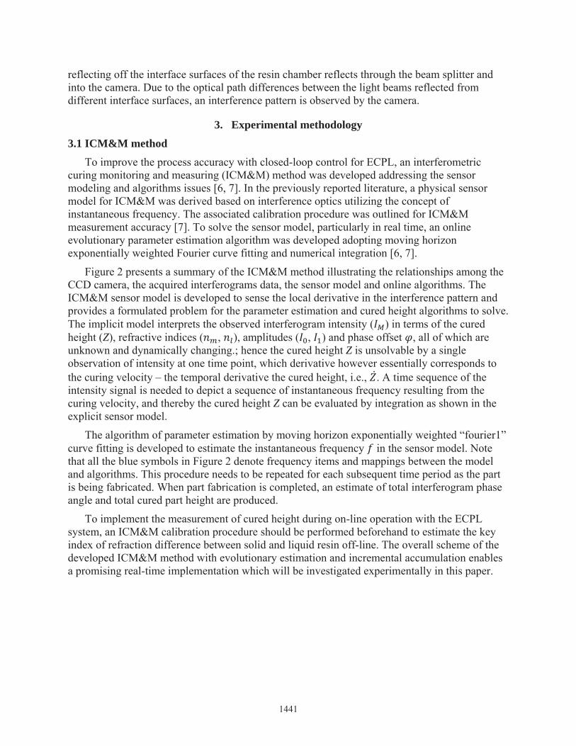
Figure 2 presents a summary of the ICM&M method illustrating the relationships among the CCD camera, the acquired interferograms data, the sensor model and online algorithms. TheICM&M sensor model is developed to sense the local derivative in the interference pattern andprovides a formulated problem for the parameter estimation and cured height algorithms to solve. The implicit model interprets the observed interferogram intensity ( ) in terms of the cured height (Z), refractive indices ( , ), amplitudes ( , ) and phase offset , all of which are unknown and dynamically changing.; hence the cured height Z is unsolvable by a single observation of intensity at one time point, which derivative however essentially corresponds to the curing velocity – the temporal derivative the cured height, i.e., ̇ . A time sequence of the intensity signal is needed to depict a sequence of instantaneous frequency resulting from the curing velocity, and thereby the cured height Z can be evaluated by integration as shown in the explicit sensor model.
The algorithm of parameter estimation by moving horizon exponentially weighted “fourier1” curve fitting is developed to estimate the instantaneous frequency in the sensor model. Note that all the blue symbols in Figure 2 denote frequency items and mappings between the model and algorithms. This procedure needs to be repeated for each subsequent time period as the part is being fabricated. When part fabrication is completed, an estimate of total interferogram phase angle and total cured part height are produced.
To implement the measurement of cured height during on-line operation with the ECPL system, an ICM&M calibration procedure should be performed beforehand to estimate the key index of refraction difference between solid and liquid resin off-line. The overall scheme of the developed ICM&M method with evolutionary estimation and incremental accumulation enables a promising real-time implementation which will be investigated experimentally in this paper.
1441
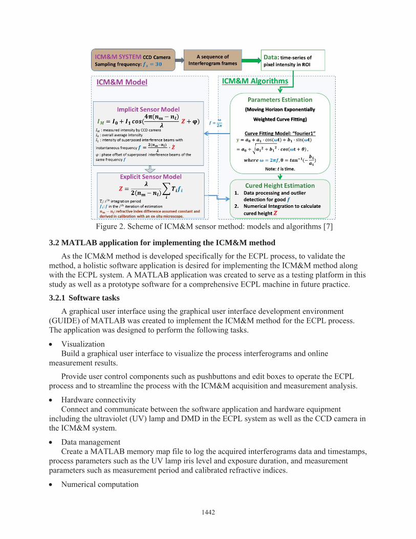
Figure 2. Scheme of ICM&M sensor method: models and algorithms [7]
3.2 MATLAB application for implementing the ICM&M methodAs the ICM&M method is developed specifically for the ECPL process, to validate the
method, a holistic software application is desired for implementing the ICM&M method along with the ECPL system. A MATLAB application was created to serve as a testing platform in thisstudy as well as a prototype software for a comprehensive ECPL machine in future practice.
3.2.1 Software tasksA graphical user interface using the graphical user interface development environment
(GUIDE) of MATLAB was created to implement the ICM&M method for the ECPL process.The application was designed to perform the following tasks.
VisualizationBuild a graphical user interface to visualize the process interferograms and online
measurement results.
Provide user control components such as pushbuttons and edit boxes to operate the ECPL process and to streamline the process with the ICM&M acquisition and measurement analysis.
Hardware connectivityConnect and communicate between the software application and hardware equipment
including the ultraviolet (UV) lamp and DMD in the ECPL system as well as the CCD camera in the ICM&M system.
Data management Create a MATLAB memory map file to log the acquired interferograms data and timestamps,
process parameters such as the UV lamp iris level and exposure duration, and measurement parameters such as measurement period and calibrated refractive indices.
Numerical computation
1442

Implement the ICM&M algorithms, and perform data analysis required for best estimation of the cured height profile of the ECPL cured part.
Report generationDocument and save into MAT-files all the data, curve fitting estimated parameters for the
sensor model, along with the measurement results of the cured heights. Display and save the results of time-height curve and ROI height profile in figures.
3.2.2 Graphical user interface and manual instructionsFigure 3 shows the application’s graphical user interface (GUI). To start with the application,
one should select from the left-bottom dropdown menu “Real-time Measurement” or “Offline Measurement”, for the former involves with real-time interferograms acquisition and simultaneous online measurement while the later replays off line an already acquired video of interferograms and performs ex-situ measurement. In this study, the application will perform measurement analysis while playing the frames, which could be taken as a simulation of the“Real-time ICM&M” doing acquisition and analysis simultaneously.
Figure 3. MATLAB application for the ECPL process measurement & control: Graphical User Interface
Measurement results show the measured height, estimated phase angle in unit of cycle which is equal to 2π rad, exposed cured height and dark cured height. If multiple points are measured, the height values are average values.
3.2.3 Computation environmentThe application is executable in MATLAB R2015b for 64-bit Operating System and can be
used in both experiment and post analysis. The real-time acquisition of the ECPL process was done in-situ on the lab desktop computer with a processor of Intel® Core(7M) i7 CPU 870 @2.93GHz 2.94GHz and an installed memory (RAM) of 16.0 GB (8.00 GB usable). All the offline ICM&M analysis was done on an ex-situ Lenovo laptop with Intel(R) Core(TM) i7-4510U CPU @ 2.00GHz 2.6 GHz and an installed memory (RAM) of 8.00 GB. Provided a more
1443

powerful multi-core processor and a high-speed camera, the ICM&M is expected to be able to run faster and more accurate measurement online with a full-field measurement capability if necessary.
3.3 Experiment designThe MATLAB application, equipped with the ICM&M method, provides a user-friendly
platform for streamlining the ECPL process and the ICM&M implementation as well as a powerful tool for testing the ICM&M method. According to the ICM&M sensor model andcalibration process [7], the experiment design incorporates a calibration experiment and a set of validation experiment.
3.3.1 Design philosophy and experiment planAs presented in the previous paper [7], a calibration procedure is required to determine the
uncertain material property of refractive index in the ICM&M method. The design of ICM&M method possesses measurement traceability by relating its measurements to a known standard –an existing well-characterized measurement system. In this study, the Olympus LEXT OLS4000 3D material confocal microscope [8] is used as a scientifically sound measurement apparatus to transfer the primary standard value of sample heights profile to the ICM&M measured object –ECPL cured part heights profile. For each new batch of material, calibration is performed once at the beginning and more times later if necessary, for instance, the material has been exposed in air too long and is likely to change in properties with oxygen diffusion etc. The derived refractive index value from calibration is assumed to be constant under the normal ECPL operating conditions so that the ICM&M measurement results are within engineering tolerance over some reasonable period of time. In this study, a bottle of material resin was prepared and used in all theexperiments which were done over a period about two weeks.
To validate the feasibility and explore the capability of the developed ICM&M method, twoseries of validation experiments were designed to cure 3D square blocks for various exposure time and under different UV intensities, respectively. Each experiment category above has its own particular purpose; meanwhile together they serve to provide a thorough investigation withone common theme - to demonstrate that the ICM&M method is reproducible and robust in measuring cured parts with precision and accuracy. Table 1 presents the overall scheme of the designed experiment that consists of one calibration experiment and two validation groups. The varying process conditions for each validation group are highlighted in red.
Table 1. Experimental Design Matrix
1444

3.3.2 ICM&M implementationIn the implementation and investigation of the ICM&M method, there are a few practical
thoughts to address in the experiment design.
First of all, choosing square blocks as target 3D objects in the experiments is because the resultant cured part with lateral aspect ratio close to if not equal 1:1 from the square bitmap projection could vividly demonstrate that ECPL process is isotropic and homogeneous and that the ICM&M method is omnidirectional.
To apply the ICM&M method in an off line mode, we replayed the curing process video, and in the last frame of the interferogram that presents a better shape of the cured part we selected a line or an area of pixels as the region of interest (ROI) to measure. Since the cured parts analyzed in this study are cuboid, theoretically it should not matter much which line to choose for measuring the height. However, considering the not-perfectly-uniform UV irradiation and stochastic process variations in the ECPL system along with some possible defects due to post-curing operation, as well as for easy visual match with the microscope measurement in later comparison of results, it is recommended to choose some features such as center lines or entire area with edge lines. The larger the ROI is chosen to be measured, the more computational time the ICM&M method needs. In the calibration, the entire area would be selected as ROI for a comprehensive analysis because its result forms the critical foundation for subsequent measurement. In the validation experiment, to speed up the analysis without influencing the results significantly, a representative profile line would be chosen as the ROI to be measured by ICM&M.
Ideally, measuring a height profile with ICM&M means measuring the cured heights of all voxels based on all pixels in the region of interest, which would be computationally tedious and costly especially in real-time ICM&M. The cured part is supposed to have a uniform heights profile due to ideally uniform UV light intensity and material properties across the curing area; hence the adjacent pixels are supposed to have very similar if not identical changed phase angles during the curing process. Interferograms pixels signal were compared, confirming the assumption of the proximity similarity in neighboring pixels’ profile. It has been found that to evaluate the height profile, measuring heights for pixels in the ROI at an interval of five pixels would not affect the accuracy significantly but requires much less computation expense than measuring every pixel for the whole area. According to the recommended practice, the pixels in measured area’s lines profile is denoted in the form of Pixels (starting pixel width coordinate:interval: ending pixel width coordinate, starting pixel height coordinate: interval: ending pixel height coordinate). For example, Pixels (245:5:365, 220) denotes a horizontal line of 25 pixels starting from Pixel (245, 220) to Pixel (365, 220) with 5 pixels between each two neighboringmeasured pixels.
Lastly, because the UV lamp in the ECPL system is designed for users to adjust its intensity in percentage scale of the “iris level”, for example, 100% means fully open iris and maximum intensity, 0% means completely closed and no irradiation at all. Hence, we used the iris level as a nominal indication of the exposure intensity applied in the ECPL process.
3.3.3 Microscope measurement practiceIn both calibration and validation experiments, we need measure the cured part using a
microscope, specifically the Olympus LEXT OLS4000 3D material confocal microscope [8],
1445

which displays directly the profile of a selected line with height measurement result. Since the cured part is designed to be a flat-top block, a profile line is supposed to be able to reveal the sample’s height regardless of the its position. In practice, however, cured samples are sometimes impacted by the post ECPL operations (e.g. removing and washing) and cannot present a perfectly smooth surface as will be seen in the experiment results. Hence, one should locate the to-be-measured line in a proper position where the surface is as intact as possible to obtain theactual height of the cured part. Preferably, two profile lines in X and Y directions (i.e. length and width dimensions), respectively, are measured and the average result is used as a better estimation of the actual height.
As a well-characterized scientific metrology equipment, the confocal microscope provides a standard reference but could also present some measurement uncertainty due to equipment operation and sample properties. In this study, to get as accurate result as possible, we tried to use higher magnification for all the sample measurement, and used two lines average asmicroscope measurement result.
4. Results and Discussion
4.1 Material formulationAs specified in earlier research [2], a trifunctional acrylate monomer - trimethylolpropane
triacrylate (TMPTA, SR-351) obtained from Sartomer was used as obtained, with thephotoinitiator 2, 2-dimethoxy-1, 2-diphenylethan-1-one (DMPA, IRGACURE-651) obtained from Ciba Specialty Chemicals, as the resin composition for the ECPL process. The DMPA photointiator concentration in the TMPTA monomer was recommended to be 20% by weight to ensure a homogenous solution. This specific formulation required less than 30 seconds to cure athick (hundreds of microns) layer of resin. In principle, a resin formulation with higher sensitivity could have been appropriate for ECPL. However, a fast curing resin system would impose a higher demand on faster and more accurate measurement and control; hence, the 20%resin formulation mentioned above was used. All the experiments done in this paper used the same bottle of material which consists of a 4:1 ratio by weight of TMPTA monomer (16 gram)and DMPA initiator (4 grams). The mixture was stirred for approximately 4 hours to form a homogeneous solution.
4.2 Calibration experimentAccording to the experiment design presented above, for the calibration, a moderate UV
intensity corresponding to the UV lamp (OmniCure® S2000) iris level at 22% was chosen so that the ECPL process cured height would not grow too fast or too slow. A 250×250 pixels square as shown in Figure 4 was displayed on DMD for 12 seconds. The ICM&M camera captured the video of interferograms when the square block part was cured by the ECPL system.To start offline ICM&M analysis, firstly the interferograms video was replayed in the MATLAB application, and the last frame of interferograms which shows the final cured part shape was extracted. In the video’s last interferogram as shown in Figure 5, the region of interest (ROI) was selected by human eyes recognition of the cured part outline, approximated by an area of150×150 pixels denoted as Pixels (235: 385, 140: 290) which is formed by the four corner pixels(info of coordinates shown in the boxes) along with the outline (red dashed line). The ICM&M method was applied to the square area of 31×31 (961) pixels designated as Pixels (235:5:385,140:5:290), which is zoned by the corner pixels being from the top-left one in a clockwise order
1446

Pixel [235, 140], Pixel [385, 140], Pixel [235, 140] and Pixel [385, 140] with 5 pixels between each two neighboring measured pixels in both width and height directions. The ICM&M model and algorithm estimated the total phase angle, ∑ ( ) in Figure 2, for each measured pixel; and the average total phase angle is 6.150 cycles (i.e., 6.150×2π rad) as shown in Figure 6.
In Figure 7, two profile lines in X direction and Y direction, respectively, are measured bythe laser confocal microscope, and the average height was calculated as . . =73.492 μm, which substitutes Z in the sensor model equation in Figure 2. The calibration process is completed by solving the equation ∆ = − = ∑ ( ) = ( . )( . )( . ) =0.022259, which value will be used in the category of validation experiments to calculate theexample parts heights to validate the ICM&M measurement capability and accuracy. Thecorresponding mean solid part refractive index is derived to be 1.49456
Figure 4. DMD pattern: 1024×768 pixels binary bitmap displaying a black square of 250×250 pixels in the center
Figure 5. Calibration: outline of the cured part in the last interferogram – ROI of Pixels (235:5:385, 140:5:290) to be measured
Figure 6. Calibration: estimated individual and average total phase angles for 31×31 pixels in the ROI of Pixels (235:5:385, 140:5:290)
1447
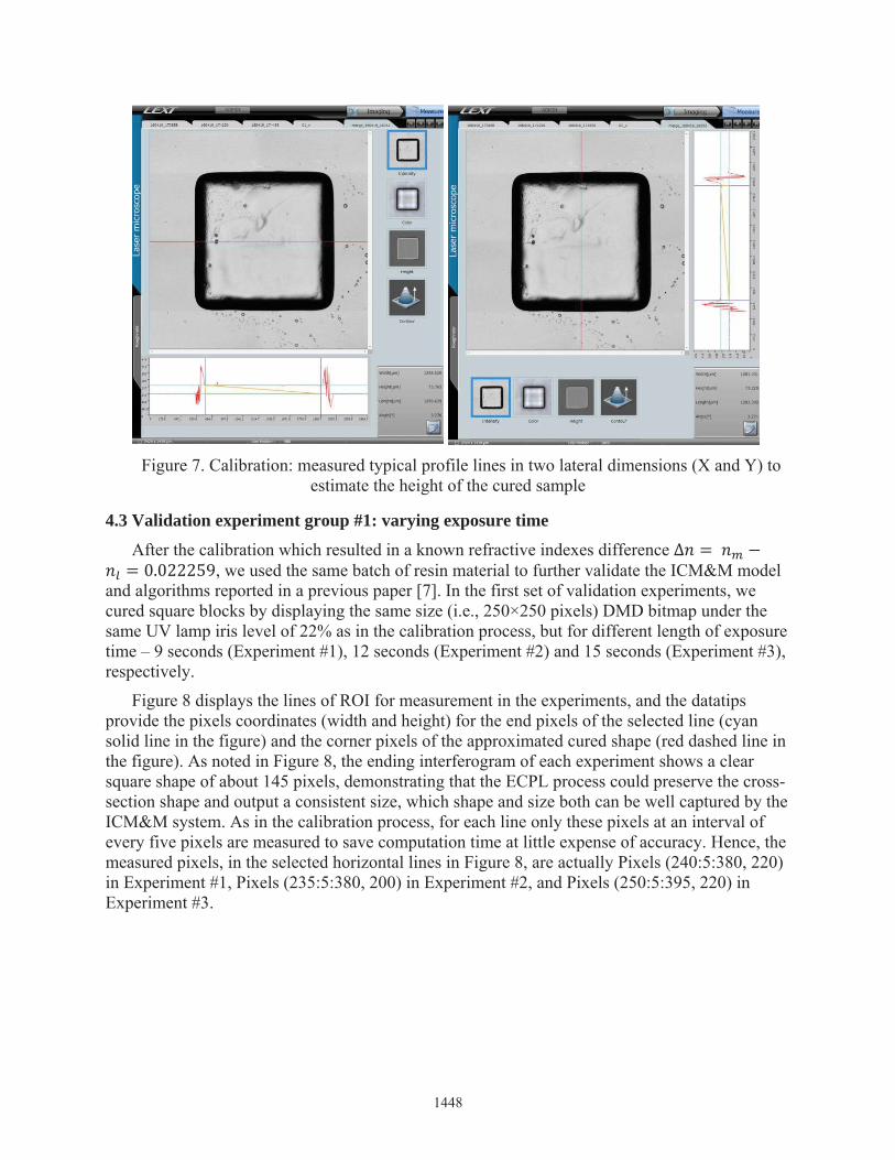
Figure 7. Calibration: measured typical profile lines in two lateral dimensions (X and Y) to estimate the height of the cured sample
4.3 Validation experiment group #1: varying exposure time
After the calibration which resulted in a known refractive indexes difference ∆ = −= 0.022259, we used the same batch of resin material to further validate the ICM&M model and algorithms reported in a previous paper [7]. In the first set of validation experiments, we cured square blocks by displaying the same size (i.e., 250×250 pixels) DMD bitmap under the same UV lamp iris level of 22% as in the calibration process, but for different length of exposure time – 9 seconds (Experiment #1), 12 seconds (Experiment #2) and 15 seconds (Experiment #3),respectively.
Figure 8 displays the lines of ROI for measurement in the experiments, and the datatipsprovide the pixels coordinates (width and height) for the end pixels of the selected line (cyan solid line in the figure) and the corner pixels of the approximated cured shape (red dashed line in the figure). As noted in Figure 8, the ending interferogram of each experiment shows a clear square shape of about 145 pixels, demonstrating that the ECPL process could preserve the cross-section shape and output a consistent size, which shape and size both can be well captured by the ICM&M system. As in the calibration process, for each line only these pixels at an interval of every five pixels are measured to save computation time at little expense of accuracy. Hence, the measured pixels, in the selected horizontal lines in Figure 8, are actually Pixels (240:5:380, 220)in Experiment #1, Pixels (235:5:380, 200) in Experiment #2, and Pixels (250:5:395, 220) in Experiment #3.
1448
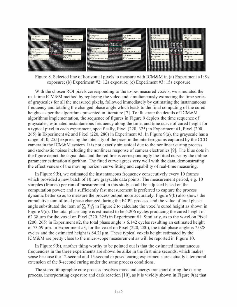
Figure 8. Selected line of horizontal pixels to measure with ICM&M in (a) Experiment #1: 9s exposure; (b) Experiment #2: 12s exposure; (c) Experiment #3: 15s exposure
With the chosen ROI pixels corresponding to the to-be-measured voxels, we simulated the real-time ICM&M method by replaying the video and simultaneously extracting the time series of grayscales for all the measured pixels, followed immediately by estimating the instantaneous frequency and totaling the changed phase angle which leads to the final computing of the cured heights as per the algorithms presented in literature [7]. To illustrate the details of ICM&M algorithms implementation, the sequence of figures in Figure 9 depicts the time sequence of grayscales, estimated instantaneous frequency along the time, and time curve of cured height for a typical pixel in each experiment, specifically, Pixel (220, 325) in Experiment #1, Pixel (200,265) in Experiment #2 and Pixel (220, 280) in Experiment #3. In Figure 9(a), the grayscale has a range of [0, 255] expressing the intensity of the pixel in the interferograms captured by the CCD camera in the ICM&M system. It is not exactly sinusoidal due to the nonlinear curing process and stochastic noises including the nonlinear response of camera electronics [9]. The blue dots in the figure depict the signal data and the red line is correspondingly the fitted curve by the online parameter estimation algorithm. The fitted curve agrees very well with the data, demonstrating the effectiveness of the moving horizon curve fitting and capability of real-time measuring.
In Figure 9(b), we estimated the instantaneous frequency consecutively every 10 frames which provided a new batch of 10 raw grayscale data points. The measurement period, e.g. 10 samples (frames) per run of measurement in this study, could be adjusted based on the computation power; and a sufficiently fast measurement is preferred to capture the process dynamic better so as to measure the process output more accurately. Figure 9(b) also shows the cumulative sum of total phase changed during the ECPL process, and the value of total phase angle substituted the item of ∑ in Figure 2 to calculate the voxel’s cured height as shown in Figure 9(c). The total phase angle is estimated to be 5.206 cycles producing the cured height of 62.38 μm for the voxel on Pixel (220, 325) in Experiment #1. Similarly, as to the voxel on Pixel (200, 265) in Experiment #2, the total phase angle is 6.142 cycles resulting an estimated height of 73.59 μm. In Experiment #3, for the voxel on Pixel (220, 280), the total phase angle is 7.028 cycles and the estimated height is 84.21μm. These typical voxels height estimated by the ICM&M are pretty close to the microscope measurement as will be reported in Figure 10.
In Figure 9(b), another thing worthy to be pointed out is that the estimated instantaneous frequencies in the three experiments are shown be alike in the first nine seconds, which makes sense because the 12-second and 15-second exposed curing experiments are actually a temporal extension of the 9-second curing under the same process conditions.
The stereolithographic cure process involves mass and energy transport during the curing process, incorporating exposure and dark reaction [10], as it is vividly shown in Figure 9(a) that
1449
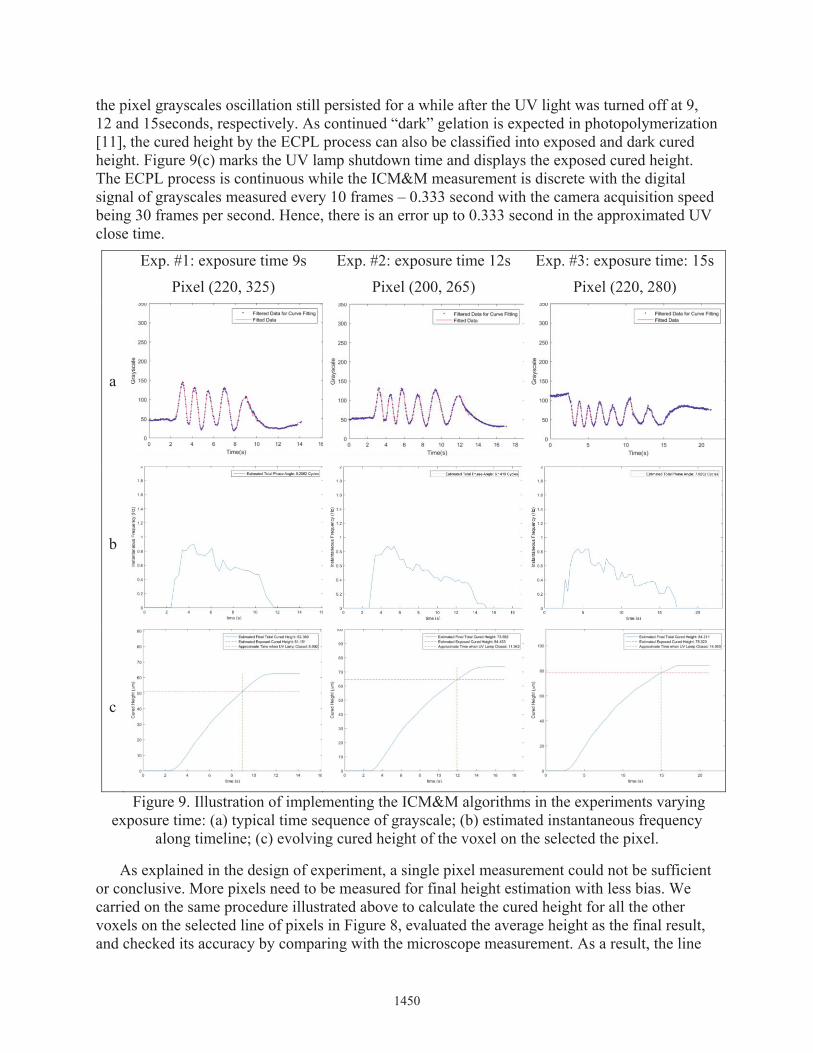
the pixel grayscales oscillation still persisted for a while after the UV light was turned off at 9, 12 and 15seconds, respectively. As continued “dark” gelation is expected in photopolymerization [11], the cured height by the ECPL process can also be classified into exposed and dark cured height. Figure 9(c) marks the UV lamp shutdown time and displays the exposed cured height. The ECPL process is continuous while the ICM&M measurement is discrete with the digital signal of grayscales measured every 10 frames – 0.333 second with the camera acquisition speed being 30 frames per second. Hence, there is an error up to 0.333 second in the approximated UV close time.
Exp. #1: exposure time 9s
Pixel (220, 325)
Exp. #2: exposure time 12s
Pixel (200, 265)
Exp. #3: exposure time: 15s
Pixel (220, 280)
a
b
c
Figure 9. Illustration of implementing the ICM&M algorithms in the experiments varying exposure time: (a) typical time sequence of grayscale; (b) estimated instantaneous frequency
along timeline; (c) evolving cured height of the voxel on the selected the pixel.
As explained in the design of experiment, a single pixel measurement could not be sufficient or conclusive. More pixels need to be measured for final height estimation with less bias. We carried on the same procedure illustrated above to calculate the cured height for all the other voxels on the selected line of pixels in Figure 8, evaluated the average height as the final result, and checked its accuracy by comparing with the microscope measurement. As a result, the line
1450
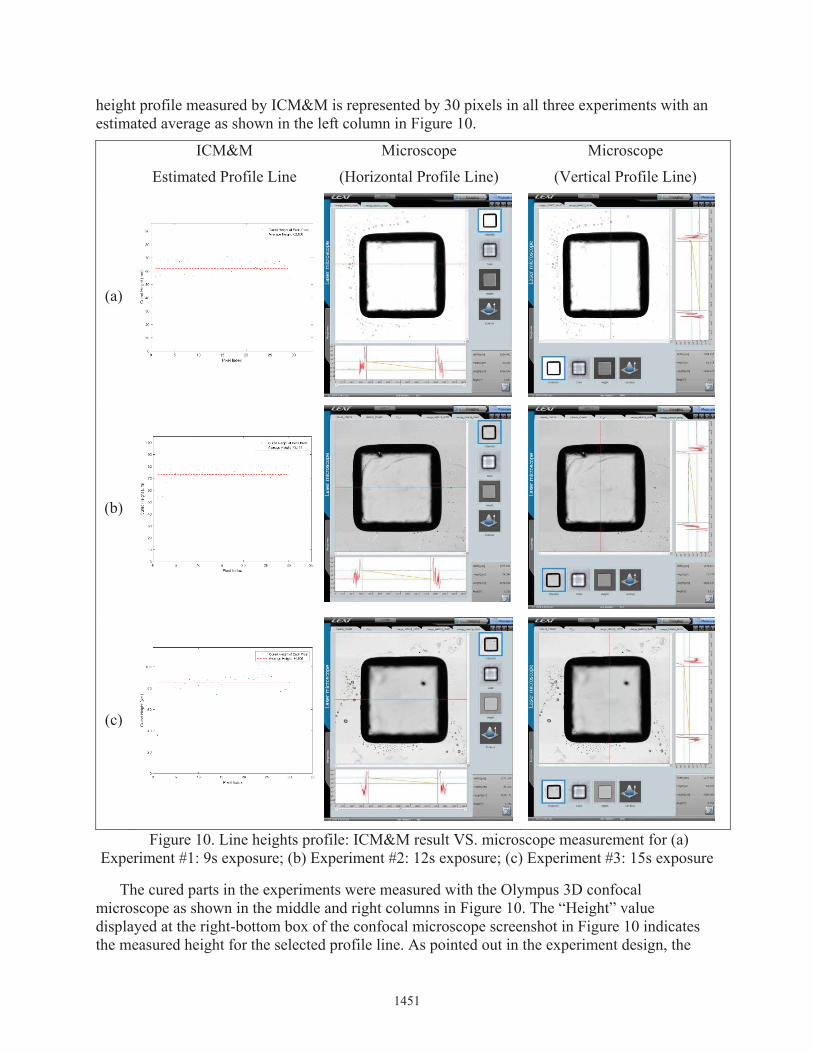
height profile measured by ICM&M is represented by 30 pixels in all three experiments with an estimated average as shown in the left column in Figure 10.
ICM&M
Estimated Profile Line
Microscope
(Horizontal Profile Line)
Microscope
(Vertical Profile Line)
(a)
(b)
(c)
Figure 10. Line heights profile: ICM&M result VS. microscope measurement for (a) Experiment #1: 9s exposure; (b) Experiment #2: 12s exposure; (c) Experiment #3: 15s exposure
The cured parts in the experiments were measured with the Olympus 3D confocal microscope as shown in the middle and right columns in Figure 10. The “Height” value displayed at the right-bottom box of the confocal microscope screenshot in Figure 10 indicates the measured height for the selected profile line. As pointed out in the experiment design, the
1451
average of measured heights for two lines in X-direction (horizontal) and Y-direction (vertical) is used as the final microscope measured height result to reduce the sample measurement bias. TheICM&M resultant average height is in good accordance with the microscope measured height in these experiments.
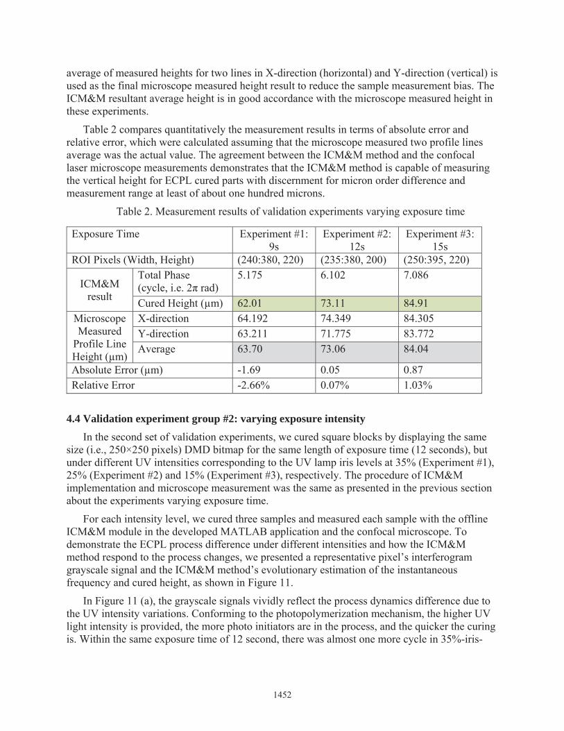
Table 2 compares quantitatively the measurement results in terms of absolute error and relative error, which were calculated assuming that the microscope measured two profile lines average was the actual value. The agreement between the ICM&M method and the confocal laser microscope measurements demonstrates that the ICM&M method is capable of measuring the vertical height for ECPL cured parts with discernment for micron order difference and measurement range at least of about one hundred microns.
Table 2. Measurement results of validation experiments varying exposure time
Exposure Time Experiment #1: 9s
Experiment #2: 12s
Experiment #3: 15s
ROI Pixels (Width, Height) (240:380, 220) (235:380, 200) (250:395, 220)
ICM&M result
Total Phase(cycle, i.e. 2π rad)
5.175 6.102 7.086
Cured Height (μm) 62.01 73.11 84.91Microscope Measured
Profile Line Height (μm)
X-direction 64.192 74.349 84.305Y-direction 63.211 71.775 83.772Average 63.70 73.06 84.04
Absolute Error (μm) -1.69 0.05 0.87Relative Error -2.66% 0.07% 1.03%
4.4 Validation experiment group #2: varying exposure intensityIn the second set of validation experiments, we cured square blocks by displaying the same
size (i.e., 250×250 pixels) DMD bitmap for the same length of exposure time (12 seconds), but under different UV intensities corresponding to the UV lamp iris levels at 35% (Experiment #1), 25% (Experiment #2) and 15% (Experiment #3), respectively. The procedure of ICM&M implementation and microscope measurement was the same as presented in the previous sectionabout the experiments varying exposure time.
For each intensity level, we cured three samples and measured each sample with the offline ICM&M module in the developed MATLAB application and the confocal microscope. Todemonstrate the ECPL process difference under different intensities and how the ICM&M method respond to the process changes, we presented a representative pixel’s interferogram grayscale signal and the ICM&M method’s evolutionary estimation of the instantaneous frequency and cured height, as shown in Figure 11.
In Figure 11 (a), the grayscale signals vividly reflect the process dynamics difference due to the UV intensity variations. Conforming to the photopolymerization mechanism, the higher UV light intensity is provided, the more photo initiators are in the process, and the quicker the curing is. Within the same exposure time of 12 second, there was almost one more cycle in 35%-iris-
1452
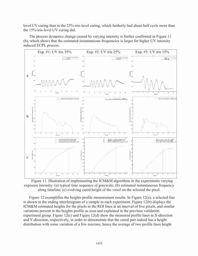
level UV curing than in the 25%-iris-level curing, which furtherly had about half cycle more than the 15%-iris-level UV curing did.
The process dynamics change caused by varying intensity is further confirmed in Figure 11(b), which shows that the estimated instantaneous frequencies is larger for higher UV intensity induced ECPL process.
Exp. #1: UV iris 35% Exp. #2: UV iris 25% Exp. #3: UV iris 15%
a
b
c
Figure 11. Illustration of implementing the ICM&M algorithms in the experiments varyingexposure intensity: (a) typical time sequence of grayscale; (b) estimated instantaneous frequency
along timeline; (c) evolving cured height of the voxel on the selected the pixel.
Figure 12 exemplifies the heights profile measurement results. In Figure 12(a), a selected lineis shown in the ending interferogram of a sample in each experiment. Figure 12(b) displays the ICM&M estimated heights for the pixels in the ROI lines at an interval of five pixels, and similar variations present in the heights profile as seen and explained in the previous validation experiment group. Figure 12(c) and Figure 12(d) show the measured profile lines in X-direction and Y-direction, respectively, in order to demonstrate that the cured part indeed has a height distribution with some variation of a few microns; hence the average of two profile lines height
1453

values is used as an estimation of the actual cured height to assess the ICM&M results as shown in Table 3.
Table 3 summarizes the measurement results in terms of absolute error and relative error, which compared the ICM&M estimated height (shaded in green) with the average of the microscope measured profile lines heights (shaded in grey). In this set of experiment, the absolute errors are less than 2 μm, which are attributed to the cued part surface roughness and profile normal distribution with expected deviations; and the less than 2% relative errors further demonstrate that the ICM&M method has excellent accuracy and sensitivity to the process input.
Exp. #1: UV iris 35% Exp. #2: UV iris 25% Exp. #3: UV iris 15%
a
b
c
1454

d
Figure 12. Measuring line heights profile: ICM&M result VS. microscope measurement for(a) Selected in the last interferogram a line of horizontal pixels to measure with ICM&M; (b)
ICM&M measured horizontal line heights profile for voxels on selected pixels; (c) Microscope measured horizontal line profile; (d) Microscope measured vertical line profile.
Table 3. Measurement results of validation experiments varying exposure intensity
4.5 Lateral measurement potentialityThough we focused on measuring the cured height in this study, a byproduct of lateral
dimensions measurement is also available. In Section 4.3, the resultant interferograms in all the three experiments show similar size of cured shape, which have approximately 145 pixels in the line corresponding to the width as shown in Figure 10. All three experiments used the same size bitmap as DMD pattern (250-by-250 pixels), and ICM&M method could retain that information of size similarity. Other than being able to qualitatively measure the lateral shape, the ICM&M is found to be able to measure quantitatively lateral dimensions according to the following calculations, which estimated successfully the width of the cured squares in Figure 10.
In an interferogram acquired by the MATLAB application, one pixel is actually a binning of four original pixels captured by the ICM&M camera. The camera pixel size is 2.2um-by-2.2um, hence a binning pixel corresponding to a pixel in the interferogram (e.g. shown in Figure 8) is8.8um-by-8.8um. Because the ICM&M optics adopts a vertical beam path reflected upward from the sample to the camera, in principal it should be a 1:1 ratio mapping. The ICM&M measured lateral size could be estimated by multiplying the value of 8.8 μm with the number of pixels inthe width dimension in the cured area shown in the interferogram (Figure 8). Hence, the estimated width of the cured square part is calculated as 145 × 8.8 = 1276 , which is in good accordance with the microscope measurement results of width - 1278.6 μm on average of all the six profile lines width as shown in Figure 10.
Total Phase(cycle, i.e. 2π rad)
Cured Height(μm)
X-direction
Y-direction
Average
35 (220:365, 240) 7.365 88.25 88.997 90.060 89.53 -1.28 -1.43%25 (230:370, 200) 6.466 77.48 78.499 77.905 78.20 -0.72 -0.93%15 (235:380, 200) 4.924 59.01 60.006 58.985 59.50 -0.49 -0.82%
Absolute Error (μm)
Relative Error
ICM&M Result Microscope Measured Profile Line Height (μm)
Exposure Intensity
(iris level)
ROI Pixels (Width, Height)
1455

Conclusively, the ICM&M system has great potentiality in measuring the lateral dimesnions of width and length as well as the vertical heights. We recommend in future work utilizing image analysis with image edge detection algorithms to measure the pixels length of cured shape forlateral dimensions information. This approach of measuring lateral dimensions for cured part is actually an alternative to the current plan of measuring the shape by measuring the heights profile across the curing area, which comes back to our research scope and priority in this study.
5. ConclusionIn this paper, to validate and fulfill the developed ICM method, an application program was
designed and created in MATLAB Graphical User Interface Development Environtment (GUIDE). The app was deployed onto the physical system integrating the ECPL and ICMautomating the ECPL process by controlling the ultraviolet lamp and digital micromirror device (DMD) mask display as well as synchronizing the ICM&M system which acquires interferograms online and can analyze the acquired data online also as long as sufficientcomputation power is available. In this study, given the limited equipment configurations and computation resource, the data analysis and measurement computation for ICM&M was performed off line. A coherent implementation of the ECPL process and ICM&M measurement was conducted with a series of experiment curing square samples by varying the factors of exposure time and intensity, to verify the measurement characteristics including discriminability, sensitivity, accuracy, precision and repeatability. A representative profile line was measured for each cured sample by both the in-house ICM&M and a commercial confocal microscope, which by comparison are in good accordance.
Future work includes curing more samples and measuring entire cured part with the ICM&M method to further verify its global measurement capability and repeatability. Also a more thorough investigation of the ICM&M characteristics including traceability, sensitivity, accuracyprecision and dispersion will be conducted.
AcknowledgmentThis material is based upon work supported by the National Science Foundation under Grant
No. CMMI-1234561. Any opinions, findings, and conclusions or recommendations expressed in this publication are those of the authors and do not necessarily reflect the views of the National Science Foundation. All the related research is patent pending.
Reference[1] Measurement Science Roadmap for Metal-Based Additive Manufacturing. 2013, National Institute of Standards and Technology (NIST) [2] Jariwala, A.S., Modeling And Process Planning For Exposure Controlled Projection Lithography. Ph.D. thesis, Mechanical Engineering, Georgia Institute of Technology, Atlanta, USA, 2013.[3] Jariwala, A.S., R.E. Schwerzel, and D.W. Rosen, Real-Time Interferometric MonitoringSystem For Exposure Controlled Projection Lithography. Proceedings of the 22nd Solid Freeform Fabrication Symposium, 2011: p. 99-108.
1456

[4] Jones, H.H., A.S. Jariwala, and D.W. Rosen, Towards Real Time Control Of Exposure Controlled Projection Lithography. Proceedings of International Symposium on Flexible Automation, 2014.[5] Jones, H.H., et al., Real-Time Selective Monitoring Of Exposure Controlled Projection Lithography. Proceedings of the 24th Solid Freeform Fabrication Symposium, 2013: p. 55-65.[6] Zhao, X. and D.W. Rosen, Parameter Estimation Based Real-Time Metrology for Exposure Controlled Projection Lithography. Proceedings of the 26th Annual International Solid Freeform Fabrication Symposium, 2015: p. 1294-1312.[7] Zhao, X. and D.W. Rosen, Real-time Interferometric Monitoring and Measuring of photopolymerization based stereolithographic additive manufacturing process: sensor model and algorithm. Measurement Science And Technology, Submitted 2016.[8] The LEXT OLS4000 3D Laser Measuring Microscope. 05-24-2016]; Available from: http://www.olympus-ims.com/en/metrology/ols4000/.[9] Colonna de Lega, X., Processing of non-stationary interference patterns - adapted phase-shifting algorithms and wavelet analysis. Application to dynamic deformation measurements by holographic and speckle interferometry. Ph.D. dissertation, Swiss Federal Institute of Technology, 1997.[10] Tang, Y., Stereolithography Cure Process Modeling. PhD, School of Chemcial & Biomolecular Engineering, Georgia Institute of Technology, Atlanta, 2005.[11] Lee, J.H., R.K. Prud’homme, and I.A. Aksay, Cure depth in photopolymerization: Experiments and theory. Journal of Materials Research, 2001. 16(21): p. 3536-3544.
1457
Related Documents