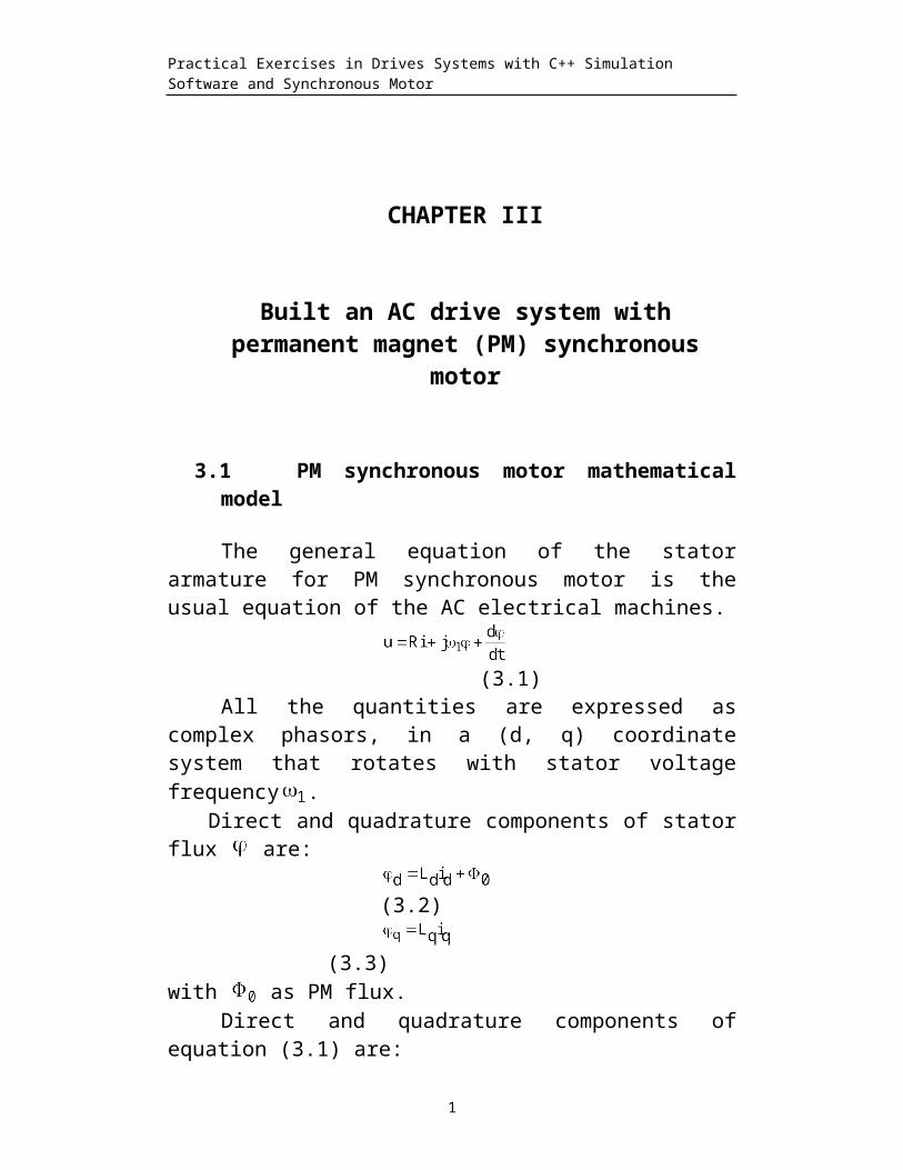
Practical Exercises in Drives Systems with C++ Simulation Software and Synchronous Motor CHAPTER III Built an AC drive system with permanent magnet (PM) synchronous motor 3.1 PM synchronous motor mathematical model The general equation of the stator armature for PM synchronous motor is the usual equation of the AC electrical machines. (3.1) All the quantities are expressed as complex phasors, in a (d, q) coordinate system that rotates with stator voltage frequency . Direct and quadrature components of stator flux are: (3.2) (3.3) with as PM flux. Direct and quadrature components of equation (3.1) are: 1

Welcome message from author
This document is posted to help you gain knowledge. Please leave a comment to let me know what you think about it! Share it to your friends and learn new things together.
Transcript
Practical Exercises in Drives Systems with C++ Simulation Software and Synchronous Motor
CHAPTER III
Built an AC drive system withpermanent magnet (PM) synchronous
motor
3.1 PM synchronous motor mathematicalmodel
The general equation of the statorarmature for PM synchronous motor is theusual equation of the AC electrical machines.
(3.1)
All the quantities are expressed ascomplex phasors, in a (d, q) coordinatesystem that rotates with stator voltagefrequency .
Direct and quadrature components of statorflux are:
(3.2)
(3.3)with as PM flux.
Direct and quadrature components ofequation (3.1) are:
1
Practical Exercises in Drives Systems with C++ Simulation Software and Synchronous Motor
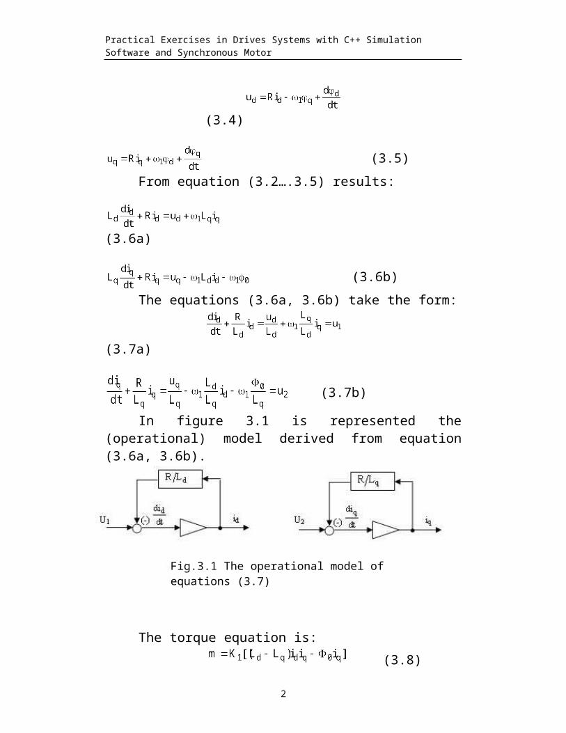
(3.4)
(3.5)From equation (3.2….3.5) results:
(3.6a)
(3.6b)The equations (3.6a, 3.6b) take the form:
(3.7a)
(3.7b)
In figure 3.1 is represented the(operational) model derived from equation(3.6a, 3.6b).
The torque equation is: (3.8)
2
Fig.3.1 The operational model of equations (3.7)

Practical Exercises in Drives Systems with C++ Simulation Software and Synchronous Motor
The transfer functions obtained fromequation (3.7a, 3.7b) are:
(3.9)
(3.10)
where Td=Ld / R , Tq=Lq / R;(3.11)
(3.12) (3.13)
(3.14)
Using z transform we have the following
discrete mathematical model for PMsynchronous machine.
Input variables: uq, ud, Output variables: id, iq,
;;
;
;
;
;
;
;
;3
Practical Exercises in Drives Systems with C++ Simulation Software and Synchronous Motor
;return;
The controls uq, ud, are subjected tothe followings conditions:
The stator voltage frequency and rotorangular frequency are synchronous
(3.15)with p as rotor pair poles and mechanicalrotor angular speed.
The stator voltages U are related withmachine flux by equation (3.1). TakingR=0 and stationary regime, we have:
(3.16)
The best command is obtained by fieldorientation. In the case id= 0 and
(3.17)We analyze first the open loop control.
From the relation (3.13) results:
(3.18)
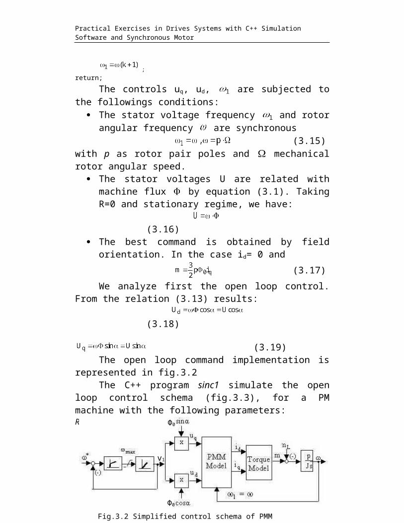
(3.19)The open loop command implementation is
represented in fig.3.2The C++ program sinc1 simulate the open
loop control schema (fig.3.3), for a PMmachine with the following parameters:R=0.6Ω; Ld=1.4*10-3H; Lq=2.8*10-3H; p=2; U=100V.
4
v1
Φ0
Φ0
Fig.3.2 Simplified control schema of PMM synchronous machine
Practical Exercises in Drives Systems with C++ Simulation Software and Synchronous Motor
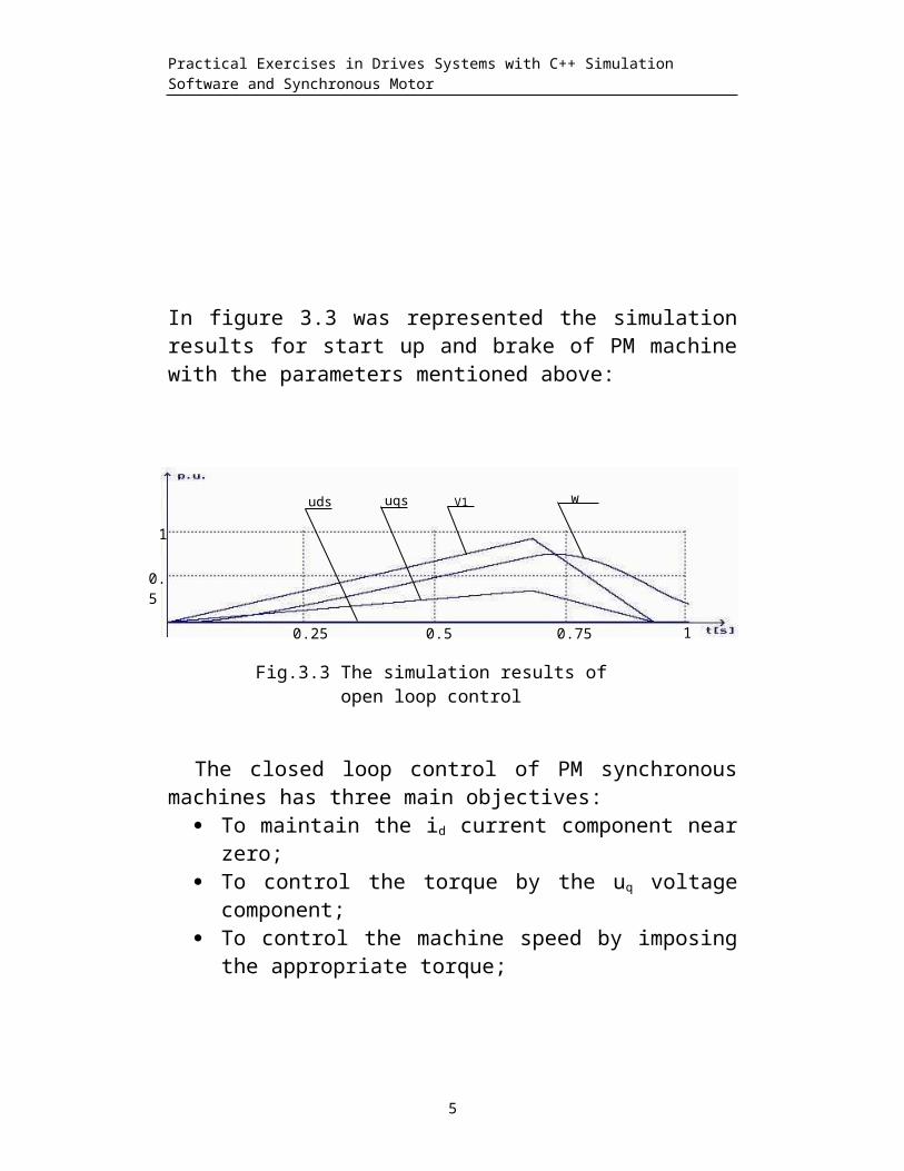
In figure 3.3 was represented the simulationresults for start up and brake of PM machinewith the parameters mentioned above:
The closed loop control of PM synchronousmachines has three main objectives:
To maintain the id current component nearzero;
To control the torque by the uq voltagecomponent;
To control the machine speed by imposingthe appropriate torque;
5
Fig.3.3 The simulation results of open loop control
0.25 0.5 0.75 1
0.5
1
uds uqs V1 w
Practical Exercises in Drives Systems with C++ Simulation Software and Synchronous Motor
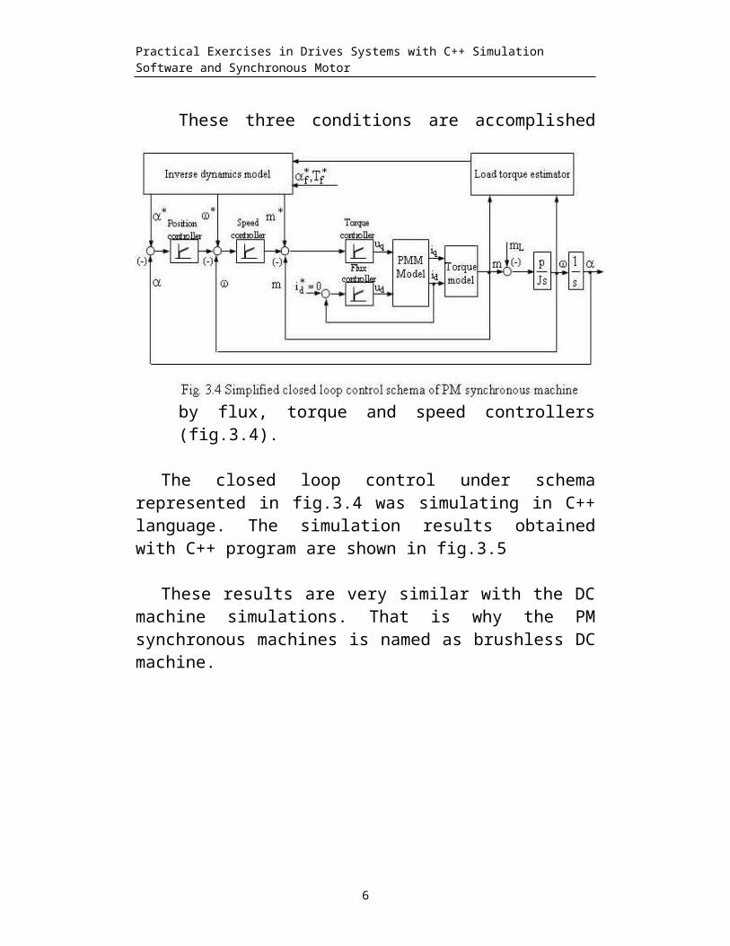
These three conditions are accomplished
by flux, torque and speed controllers(fig.3.4).
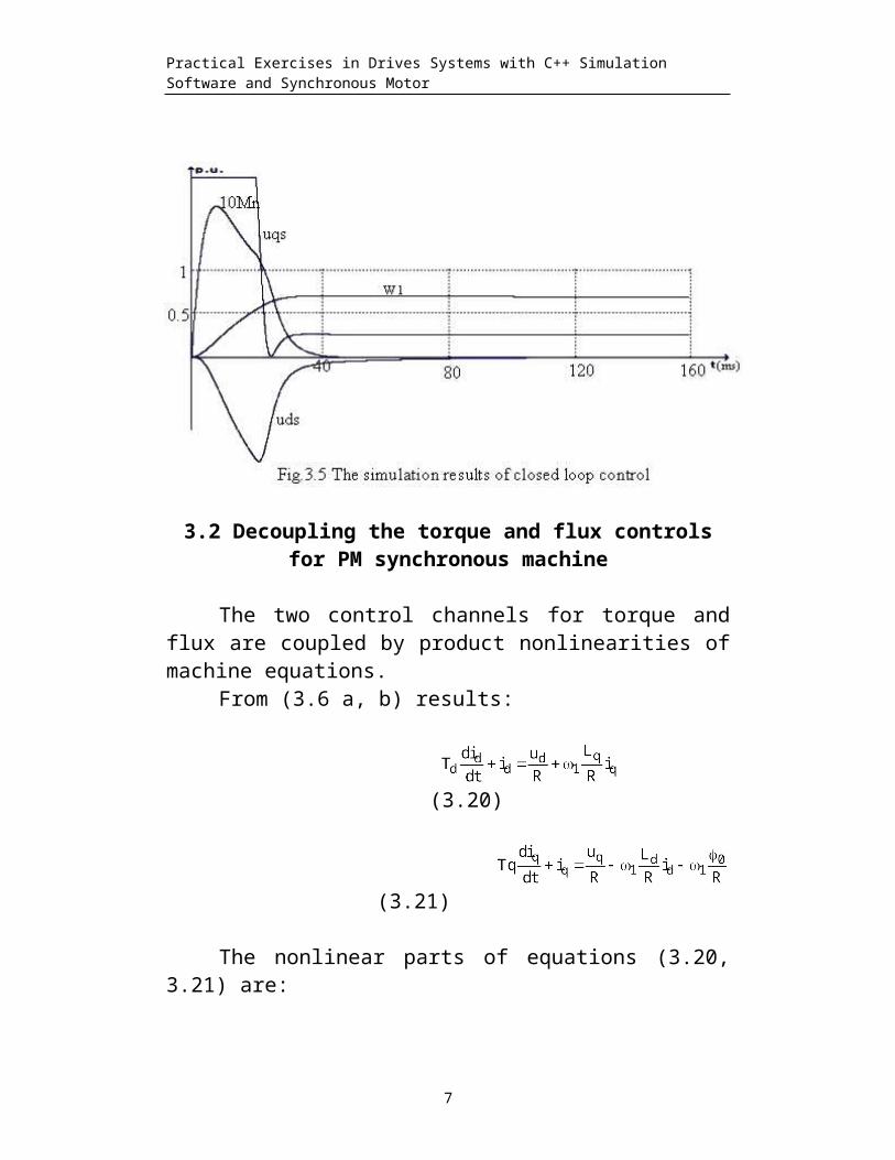
The closed loop control under schemarepresented in fig.3.4 was simulating in C++language. The simulation results obtainedwith C++ program are shown in fig.3.5
These results are very similar with the DCmachine simulations. That is why the PMsynchronous machines is named as brushless DCmachine.
6
Practical Exercises in Drives Systems with C++ Simulation Software and Synchronous Motor
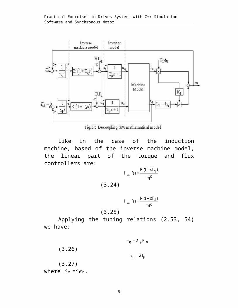
3.2 Decoupling the torque and flux controlsfor PM synchronous machine
The two control channels for torque andflux are coupled by product nonlinearities ofmachine equations.
From (3.6 a, b) results:
(3.20)
(3.21)
The nonlinear parts of equations (3.20,3.21) are:
7

Practical Exercises in Drives Systems with C++ Simulation Software and Synchronous Motor
(3.22)
(3.23)
The two controllers, for torque and flux,must to generate the and voltagecomponents in such a way that machine remainsalways flux orientated. That means, if the id
current component is maintained nearly zeroby the flux controller, the torque willdepends mainly of the iq current component(see relation 3.8). Because the inverter thatsupply the motor is voltage controlled, itmust determine the relations between thecurrent controls , and the correspondingvoltage controls , . That is made byinverse model which results from equations(3.20, 3.21).
8
Practical Exercises in Drives Systems with C++ Simulation Software and Synchronous Motor
Like in the case of the inductionmachine, based of the inverse machine model,the linear part of the torque and fluxcontrollers are:
(3.24) (3.25)
Applying the tuning relations (2.53, 54)we have:
(3.26)
(3.27)
where .
9
Practical Exercises in Drives Systems with C++ Simulation Software and Synchronous Motor
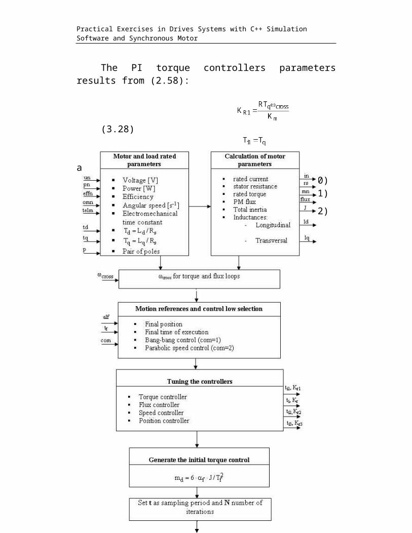
The PI torque controllers parametersresults from (2.58):
(3.28)
(3.29)
and for flux controller(3.30)(3.31)(3.32)
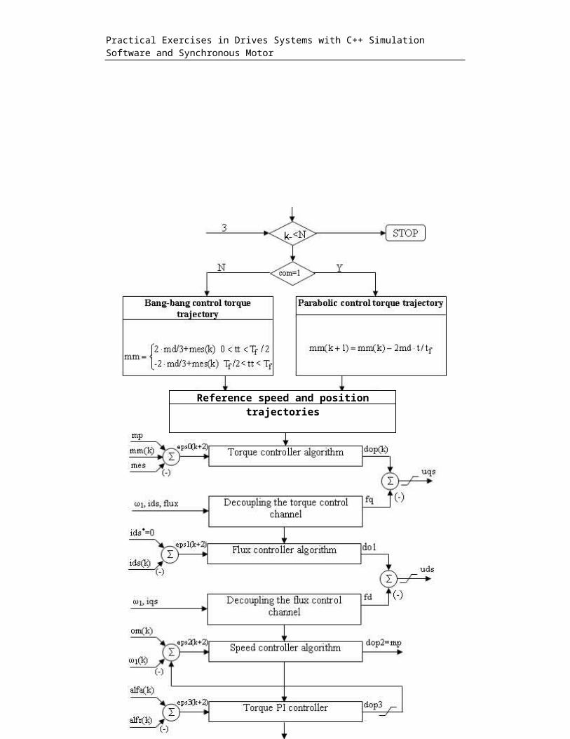
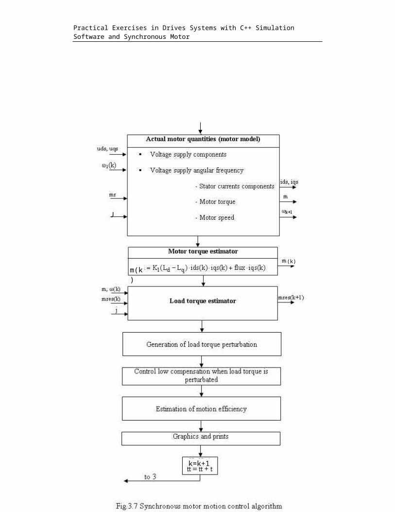
3.3 The simulation algorithm of themotion system
10
Practical Exercises in Drives Systems with C++ Simulation Software and Synchronous Motor
11
Reference speed and position trajectories
k
Practical Exercises in Drives Systems with C++ Simulation Software and Synchronous Motor
12
J
m(k)
(k)
k=k+1
Practical Exercises in Drives Systems with C++ Simulation Software and Synchronous Motor
3.4 Experimental results 13
Practical Exercises in Drives Systems with C++ Simulation Software and Synchronous Motor
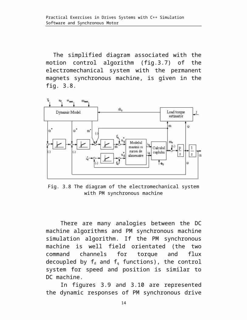
The simplified diagram associated with themotion control algorithm (fig.3.7) of theelectromechanical system with the permanentmagnets synchronous machine, is given in thefig. 3.8.
There are many analogies between the DCmachine algorithms and PM synchronous machinesimulation algorithm. If the PM synchronousmachine is well field orientated (the twocommand channels for torque and fluxdecoupled by fd and fq functions), the controlsystem for speed and position is similar toDC machine.
In figures 3.9 and 3.10 are representedthe dynamic responses of PM synchronous drive
14
Fig. 3.8 The diagram of the electromechanical system with PM synchronous machine
Practical Exercises in Drives Systems with C++ Simulation Software and Synchronous Motor
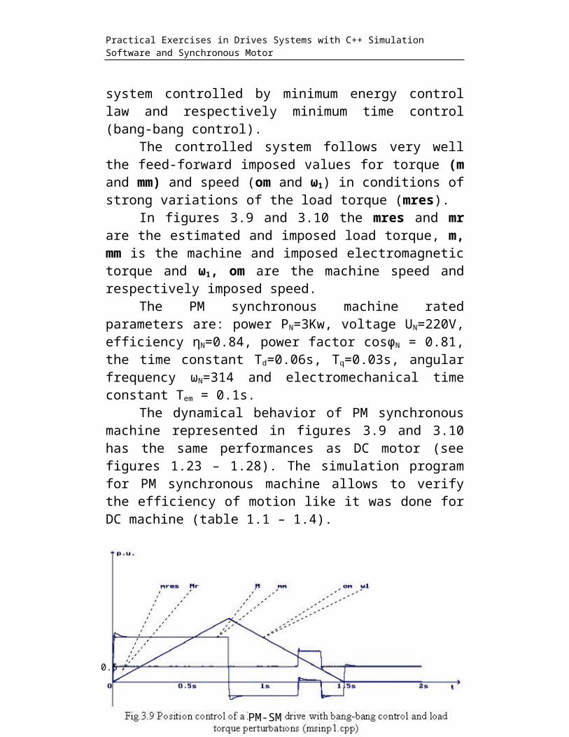
system controlled by minimum energy controllaw and respectively minimum time control(bang-bang control).
The controlled system follows very wellthe feed-forward imposed values for torque (mand mm) and speed (om and ω1) in conditions ofstrong variations of the load torque (mres).
In figures 3.9 and 3.10 the mres and mrare the estimated and imposed load torque, m,mm is the machine and imposed electromagnetictorque and ω1, om are the machine speed andrespectively imposed speed.
The PM synchronous machine ratedparameters are: power PN=3Kw, voltage UN=220V,efficiency ηN=0.84, power factor cosφN = 0.81,the time constant Td=0.06s, Tq=0.03s, angularfrequency ωN=314 and electromechanical timeconstant Tem = 0.1s.
The dynamical behavior of PM synchronousmachine represented in figures 3.9 and 3.10has the same performances as DC motor (seefigures 1.23 – 1.28). The simulation programfor PM synchronous machine allows to verifythe efficiency of motion like it was done forDC machine (table 1.1 – 1.4).
15
PM-SM
0.5
Practical Exercises in Drives Systems with C++ Simulation Software and Synchronous Motor
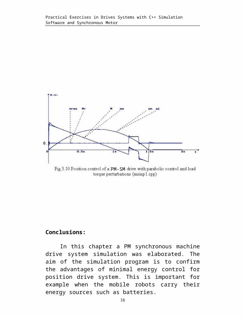
Conclusions:
In this chapter a PM synchronous machinedrive system simulation was elaborated. Theaim of the simulation program is to confirmthe advantages of minimal energy control forposition drive system. This is important forexample when the mobile robots carry theirenergy sources such as batteries.
16
PM-SM
0.5
Practical Exercises in Drives Systems with C++ Simulation Software and Synchronous Motor
First the PM synchronous machine modelwas developed in rotor field orientationtheory. Than we used the minimal energycontrol law presented in section 1 forgeneration of the optimal trajectories fortorque, speed and position. A feed-forwardcontrol system commands the motor actuator(PWM inverter) in order to follow as well apossible the imposed trajectories as well aspossible.
All the techniques used in the simulationprogram (the load and electromagnetic torqueestimators, the tuning methods for torque andflux controllers, the optimal trajectoriesgeneration) are well suited for directimplementation in a real drive system.
17
Related Documents