ELEC0029 - Electric Power System Analysis The synchronous machine (detailed model) Thierry Van Cutsem [email protected] www.montefiore.ulg.ac.be/~vct February 2018 1 / 36

Welcome message from author
This document is posted to help you gain knowledge. Please leave a comment to let me know what you think about it! Share it to your friends and learn new things together.
Transcript
ELEC0029 - Electric Power System Analysis
The synchronous machine(detailed model)
Thierry Van [email protected] www.montefiore.ulg.ac.be/~vct
February 2018
1 / 36
The synchronous machine
Objectives
Extend the model of the synchronous machine considered in course ELEC0014:
more detailed
appropriate for dynamic studies
includes the effect of damper windings
applicable to machines with salient-pole rotors (hydro power plants)
Relies on the Park transformation, also used for other power system components.
2 / 36
The synchronous machine The two types of synchronous machines
The two types of synchronous machines
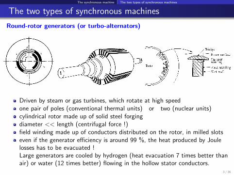
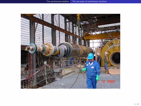
Round-rotor generators (or turbo-alternators)
Driven by steam or gas turbines, which rotate at high speedone pair of poles (conventional thermal units) or two (nuclear units)cylindrical rotor made up of solid steel forgingdiameter << length (centrifugal force !)field winding made up of conductors distributed on the rotor, in milled slotseven if the generator efficiency is around 99 %, the heat produced by Joulelosses has to be evacuated !Large generators are cooled by hydrogen (heat evacuation 7 times better thanair) or water (12 times better) flowing in the hollow stator conductors.
3 / 36
The synchronous machine The two types of synchronous machines
4 / 36

The synchronous machine The two types of synchronous machines
Salient-pole generators
Driven by hydraulic turbines (or diesel engines), which rotate at low speed
many pairs of poles (at least 4) ⇒ it is more convenient to have fieldwindings concentrated and placed on the poles
air gap is not constant: min. in front of a pole, max. in between two poles
poles are shaped to also minimize space harmonics
diameter >> length (to have space for the many poles)
rotor is laminated (poles easier to construct)
generators usually cooled by the flow of air around the rotor.5 / 36

The synchronous machine The two types of synchronous machines
6 / 36

The synchronous machine The two types of synchronous machines
Damper windings and eddy currents in rotor
Damper windings (or amortisseur)
round-rotor machines: copper/brass bars placed in the same slots at the fieldwinding, and interconnected to form a damper cage (similar to the squirrelcage of an induction motor)salient-pole machines: copper/brass rods embedded in the poles andconnected at their ends to rings or segments.
Why?in perfect steady state: the magnetic fields produced by both the stator andthe rotor are fixed relative to the rotor ⇒ no current induced in dampersafter a disturbance: the rotor moves with respect to stator magnetic field⇒ currents are induced in the dampers. . .. . . which, according to Lenz’s law, create a damping torque helping the rotorto align on the stator magnetic field.
Eddy currents in the rotor
Round-rotor generators: the solid rotor offers a path for eddy currents, whichproduce an effect similar to those of amortisseurs.
7 / 36

The synchronous machine Modelling of machine with magnetically coupled circuits
Modelling of machine with magnetically coupled circuits
Number of rotor windings = degree of sophistication of model. But:
more detailed model ⇒ more data are neededwhile measurement devices can be connected only to the field winding.
Most widely used model: 3 or 4 rotor windings:
f : field winding d1, q1: amortisseursq2: accounts for eddy currents in rotor; not used in (laminated) salient-polegenerators.
8 / 36

The synchronous machine Modelling of machine with magnetically coupled circuits
Remarks
In the sequel, we consider:
a machine with a single pair of poles, for simplicity.This does not affect the electrical behaviour of the generator(it affects the moment of inertia and the kinetic energy of rotating masses)
the general case of a salient-pole machine.For a round-rotor machine: set some parameters to the same value in the dand q axes (to account for the equal air gap width)
the configuration with four rotor windings (f , d1, q1, q2).For a salient-pole generator : remove the q2 winding.
9 / 36
The synchronous machine Modelling of machine with magnetically coupled circuits
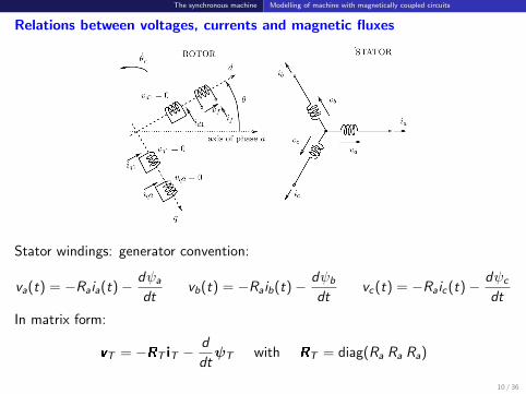
Relations between voltages, currents and magnetic fluxes
Stator windings: generator convention:
va(t) = −Raia(t)− dψa
dtvb(t) = −Raib(t)− dψb
dtvc (t) = −Raic (t)− dψc
dt
In matrix form:
vT = −RT iT −d
dtψT with RT = diag(Ra Ra Ra)
10 / 36

The synchronous machine Modelling of machine with magnetically coupled circuits
Rotor windings: motor convention:
vf (t) = Rf if (t) +dψf
dt
0 = Rd1id1(t) +dψd1
dt
0 = Rq1iq1(t) +dψq1
dt
0 = Rq2iq2(t) +dψq2
dt
In matrix form:
vr = Rr ir +d
dtψr with Rr = diag(Rf Rd1 Rq1 Rq2)
11 / 36

The synchronous machine Modelling of machine with magnetically coupled circuits
Inductances
Saturation being neglected, the fluxes vary linearly with the currents according to:[ψT
ψr
]=
[LTT (θr ) LTr (θr )LT
Tr (θr ) Lrr
] [iT
ir
]LTT and LTr vary with the position θr of the rotor
but Lrr does not
the components of LTT and LTr are periodic functions of θr obviously
the space harmonics in θr are assumed negligible = sinusoidal machineassumption.
12 / 36

The synchronous machine Modelling of machine with magnetically coupled circuits
LTT (θr ) = L0 + L1 cos 2θr −Lm − L1 cos 2(θr + π6 ) −Lm − L1 cos 2(θr − π
6 )−Lm − L1 cos 2(θr + π
6 ) L0 + L1 cos 2(θr − 2π3 ) −Lm − L1 cos 2(θr + π
2 )−Lm − L1 cos 2(θr − π
6 ) −Lm − L1 cos 2(θr + π2 ) L0 + L1 cos 2(θr + 2π
3 )
Lo , L1, Lm > 0
13 / 36

The synchronous machine Modelling of machine with magnetically coupled circuits
LTr (θr ) = Laf cos θr Lad1 cos θr Laq1 sin θr Laq2 sin θr
Laf cos(θr − 2π3 ) Lad1 cos(θr − 2π
3 ) Laq1 sin(θr − 2π3 ) Laq2 sin(θr − 2π
3 )Laf cos(θr + 2π
3 ) Lad1 cos(θr + 2π3 ) Laq1 sin(θr + 2π
3 ) Laq2 sin(θr + 2π3 )
Laf , Lad1, Laq1, Laq2 > 0
14 / 36
The synchronous machine Modelling of machine with magnetically coupled circuits
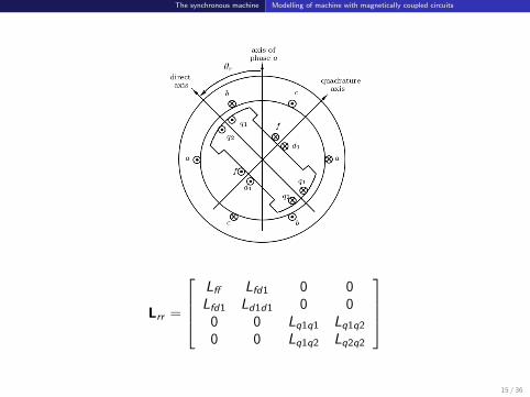
Lrr =
Lff Lfd1 0 0Lfd1 Ld1d1 0 0
0 0 Lq1q1 Lq1q2
0 0 Lq1q2 Lq2q2
15 / 36

The synchronous machine Park transformation and equations
Park transformation and equations
Park transformation
is applied to stator variables (denoted .T ) to obtain the corresponding Parkvariables (denoted .P ):
vP = P vT
ψP = P ψT
iP = P iT
where P =
√2
3
cos θr cos(θr − 2π3 ) cos(θr + 2π
3 )sin θr sin(θr − 2π
3 ) sin(θr + 2π3 )
1√2
1√2
1√2
vP =
[vd vq vo
]TψP =
[ψd ψq ψo
]TiP =
[id iq io
]TIt is easily shown that: P PT = I ⇔ P−1 = PT
16 / 36

The synchronous machine Park transformation and equations
Interpretation
Total magnetic field created by the currents ia, ib et ic :
projected on d axis: k (cos θr ia + cos(θr −2π
3) ib + cos(θr −
4π
3) ic ) = k
√3
2id
projected on q axis: k (sin θr ia + sin(θr −2π
3) ib + sin(θr −
4π
3) ic ) = k
√3
2iq
The Park transformation consists of replacingthe (a, b, c) stator windings by three equivalentwindings (d , q, o):
the d winding is attached to the d axis
the q winding is attached to the q axis
the currents id and iq produce together thesame magnetic field, to the multiplicative
constant√
32 .
17 / 36
The synchronous machine Park transformation and equations
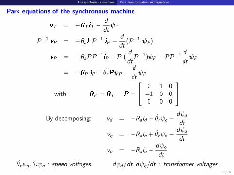
Park equations of the synchronous machine
vT = −RT iT −d
dtψT
P−1 vP = −RaI P−1 iP −d
dt(P−1 ψP )
vP = −RaPP−1iP − P (d
dtP−1)ψP − PP−1
d
dtψP
= −RP iP − θrPψP −d
dtψP
with: RP = RT P =
0 1 0−1 0 00 0 0
By decomposing: vd = −Raid − θrψq −
dψd
dt
vq = −Raiq + θrψd −dψq
dt
vo = −Raio −dψo
dt
θrψd , θrψq : speed voltages dψd/dt, dψq/dt : transformer voltages18 / 36
The synchronous machine Park transformation and equations
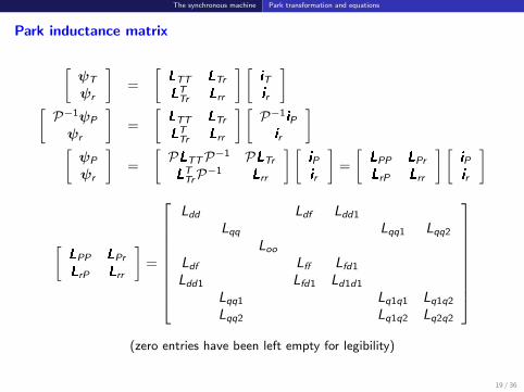
Park inductance matrix
[ψT
ψr
]=
[LTT LTr
LTTr Lrr
] [iT
ir
][P−1ψP
ψr
]=
[LTT LTr
LTTr Lrr
] [P−1iPir
][ψP
ψr
]=
[PLTTP−1 PLTr
LTTrP−1 Lrr
] [iP
ir
]=
[LPP LPr
LrP Lrr
] [iP
ir
]
[LPP LPr
LrP Lrr
]=
Ldd Ldf Ldd1
Lqq Lqq1 Lqq2
Loo
Ldf Lff Lfd1
Ldd1 Lfd1 Ld1d1
Lqq1 Lq1q1 Lq1q2
Lqq2 Lq1q2 Lq2q2
(zero entries have been left empty for legibility)
19 / 36

The synchronous machine Park transformation and equations
with:
Ldd = L0 + Lm +3
2L1
Lqq = L0 + Lm −3
2L1
Ldf =
√3
2Laf
Ldd1 =
√3
2Lad1
Lqq1 =
√3
2Laq1
Lqq2 =
√3
2Laq2
Loo = L0 − 2Lm
All components are independent of the rotor position θr . That was expected !
There is no magnetic coupling between d and q axes(this was already assumed in LTr and Lrr : zero mutual inductances betweencoils with orthogonal axes).
20 / 36

The synchronous machine Park transformation and equations
Leaving aside the o component andgrouping (d , f , d1), on one hand, and (q, q1, q2), on the other hand:
vd
−vf
0
= −
Ra
Rf
Rd1
idifid1
− θrψq
00
− d
dt
ψd
ψf
ψd1
vq
00
= −
Ra
Rq1
Rq2
iqiq1iq2
+
θrψd
00
− d
dt
ψq
ψq1
ψq2
with the following flux-current relations: ψd
ψf
ψd1
=
Ldd Ldf Ldd1
Ldf Lff Lfd1
Ldd1 Lfd1 Ld1d1
idifid1
ψq
ψq1
ψq2
=
Lqq Lqq1 Lqq2
Lqq1 Lq1q1 Lq1q2
Lqq2 Lq1q2 Lq2q2
iqiq1iq2
21 / 36

The synchronous machine Energy, power and torque
Energy, power and torque
Balance of power at stator:
pT + pJs +dWms
dt= pr→s
pT : three-phase instantaneous power leaving the statorpJs : Joule losses in stator windingsWms : magnetic energy stored in the stator windingspr→s : power transfer from rotor to stator (mechanical ? electrical ?)
Three-phase instantaneous power leaving the stator :
pT (t) = vaia + vb ib + vc ic = vTT iT = v
TP PPT
iP = vTP iP = vd id + vq iq + vo io
= − (Rai2d + Rai
2q + Rai
2o )︸ ︷︷ ︸
pJs
− (iddψd
dt+ iq
dψq
dt+ io
dψo
dt)︸ ︷︷ ︸
dWms/dt
+θr (ψd iq − ψq id )
⇒ pr→s = θr (ψd iq − ψq id )
22 / 36
The synchronous machine Energy, power and torque
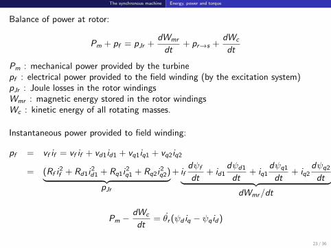
Balance of power at rotor:
Pm + pf = pJr +dWmr
dt+ pr→s +
dWc
dt
Pm : mechanical power provided by the turbinepf : electrical power provided to the field winding (by the excitation system)pJr : Joule losses in the rotor windingsWmr : magnetic energy stored in the rotor windingsWc : kinetic energy of all rotating masses.
Instantaneous power provided to field winding:
pf = vf if = vf if + vd1id1 + vq1iq1 + vq2iq2
= (Rf i2f + Rd1i
2d1 + Rq1i
2q1 + Rq2i
2q2)︸ ︷︷ ︸
pJr
+ ifdψf
dt+ id1
dψd1
dt+ iq1
dψq1
dt+ iq2
dψq2
dt︸ ︷︷ ︸dWmr/dt
Pm −dWc
dt= θr (ψd iq − ψq id )
23 / 36

The synchronous machine Energy, power and torque
Equation of rotor motion:
I d2θr
dt2= Tm − Te
I : moment of inertia of all the rotating massesTm : mechanical torque applied to the rotor by the turbineTe : electromagnetic torque applied to the rotor by the generator.
Multiplying the above equation by θr :
I θr θr = θrTm − θrTe
dWc
dt= Pm − θrTe
Pm : mechanical power provided by the turbine.
Hence, the (compact and elegant !) expression of the electromagnetic torque is:
Te = ψd iq − ψq id
Note. The power transfer pr→s from rotor to stator is of mechanical nature only.24 / 36

The synchronous machine Energy, power and torque
The various components of the torque Te
Te = Ldd id iq + Ldf if iq + Ldd1id1iq − Lqq iq id − Lqq1iq1id − Lqq2iq2id
(Ldd − Lqq) id iq : synchronous torque due to rotor saliency
exists in salient-pole machines only
even without excitation (if = 0), the rotor tends to align its direct axis withthe axis of the rotating magnetic field created by the stator currents,offering to the latter a longer path in iron
a significant fraction of the total torque in a salient-pole generator.
Ldd1 id1iq − Lqq1iq1id − Lqq2iq2id : damping torque
due to currents induced in the amortisseurs
zero in steady-state operation.
Ldf if iq : only component involving the field current ifthe main part of the total torque in steady-state operation
in steady state, it is the synchronous torque due to excitation
during transients, the field winding also contributes to the damping torque.25 / 36

The synchronous machine The synchronous machine in steady state
The synchronous machine in steady state
Balanced three-phase currents of angular frequency ωN flow in the statorwindings
a direct current flows in the field winding subjected to a constant excitationvoltage:
if =Vf
Rf
the rotor rotates at the synchronous speed:
θr = θor + ωNt
no current is induced in the other rotor circuits:
id1 = iq1 = iq2 = 0
26 / 36

The synchronous machine The synchronous machine in steady state
Operation with stator opened
ia = ib = ic = 0
⇒ id = iq = io = 0
⇒ ψd = Ldf if and ψq = 0
Park equations:
vd = 0
vq = ωNψd = ωNLdf if
Getting back to the stator voltages, e.g. in phase a :
va(t) =
√2
3ωNLdf if sin(θo
r + ωNt) =√
2Eq sin(θor + ωNt)
Eq =ωNLdf if√
3= e.m.f. proportional to excitation current
= RMS voltage at the terminal of the opened machine.
27 / 36

The synchronous machine The synchronous machine in steady state
Operation under load
va(t) =√2V cos(ωN t+θ) vb(t) =
√2V cos(ωN t+θ−
2π
3) vc (t) =
√2V cos(ωN t+θ+
2π
3)
ia(t) =√2I cos(ωN t +ψ) ib(t) =
√2I cos(ωN t +ψ−
2π
3) ic (t) =
√2I cos(ωN t +ψ+
2π
3)
id =
√2
3
√2I [cos(θo
r + ωN t) cos(ωN t + ψ) + cos(θor + ωN t −
2π
3) cos(ωN t + ψ −
2π
3)
+ cos(θor + ωN t +
2π
3) cos(ωN t + ψ +
2π
3)]
=I√3[cos(θo
r + 2ωN t + ψ) + cos(θor + 2ωN t + ψ −
4π
3) + cos(θo
r + 2ωN t + ψ +4π
3)
+3 cos(θor − ψ)] =
√3I cos(θo
r − ψ)
Similarly:
iq =√
3I sin(θor − ψ) io = 0
vd =√
3V cos(θor − θ) vq =
√3V sin(θo
r − θ) vo = 0
In steady-state, id and iq are constant. This was expected !28 / 36
The synchronous machine The synchronous machine in steady state
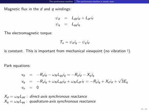
Magnetic flux in the d and q windings:
ψd = Ldd id + Ldf if
ψq = Lqq iq
The electromagnetic torque:
Te = ψd iq − ψq id
is constant. This is important from mechanical viewpoint (no vibration !).
Park equations:
vd = −Raid − ωNLqq iq = −Raid − Xq iq
vq = −Raiq + ωNLdd id + ωNLdf if = −Raiq + Xd id +√
3Eq
vo = 0
Xd = ωNLdd : direct-axis synchronous reactanceXq = ωNLqq : quadrature-axis synchronous reactance
29 / 36

The synchronous machine The synchronous machine in steady state
Phasor diagram
The Park equations become:
V cos(θor − θ) = −RaI cos(θo
r − ψ)− XqI sin(θor − ψ)
V sin(θor − θ) = −RaI sin(θo
r − ψ) + Xd I cos(θor − ψ) + Eq
which are the projections on the d and q axes of the complex equation:
Eq = V + Ra I + jXd Id + jXq Iq
30 / 36

The synchronous machine The synchronous machine in steady state
Particular case : round-rotor machine: Xd = Xq = X
Eq = V + Ra I + jX (Id + Iq) = V + Ra I + jX I
Such an equivalent circuit cannot be derived for a salient-pole generator.
31 / 36

The synchronous machine The synchronous machine in steady state
Powers
Eq = Eqej(θo
r −π2 )
Id = I cos(θor − ψ)e jθo
r =id√
3e jθo
r Iq = I sin(θor − ψ)e j(θo
r −π2 ) = −j iq√
3e jθo
r
I = Id + Iq = (id√
3− j
iq√3
)e jθor
Vd = V cos(θor − θ)e jθo
r =vd√
3e jθo
r Vq = V sin(θor − θ)e j(θo
r −π2 ) = −j vq√
3e jθo
r
V = Vd + Vq = (vd√
3− j
vq√3
)e jθor
32 / 36

The synchronous machine The synchronous machine in steady state
Three-phase complex power produced by the machine:
S = 3V I ? = 3 (vd√
3− j
vq√3
)(id√
3+ j
iq√3
) = (vd − j vq)(id + j iq)
⇒ P = vd id + vq iq Q = vd iq − vq id
P and Q as functions of V , Eq and the internal angle δ, assuming Ra ' 0 ?
vd = −Xq iq ⇒ iq = − vd
Xq
vq = Xd id +√
3Eq ⇒ id =vq −
√3Eq
Xd
vd =√
3V cos(θor − θ) = −
√3V sin δ
vq =√
3V sin(θor − θ) =
√3V cos δ
P = 3EqV
Xdsin δ+
3V 2
2(
1
Xq− 1
Xd) sin 2δ Q = 3
EqV
Xdcos δ−3V 2(
sin2 δ
Xq+
cos2 δ
Xd)
Case of a round-rotor machine: P = 3EqV
Xsin δ Q = 3
EqV
Xcos δ − 3
V 2
X33 / 36

The synchronous machine Nominal values, per unit system and orders of magnitudes
Nominal values, per unit system and orders of magnitudes
Stator
nominal voltage UN : voltage for which the machine has been designed (inparticular its insulation).The real voltage may deviate from this value by a few %
nominal current IN : current for which machine has been designed (inparticular the cross-section of its conductors).Maximum current that can be accepted without limit in time
nominal apparent power: SN =√
3UN IN .
Conversion of parameters in per unit values:
base power: SB = SN
base voltage: VB = UN/√
3
base current: IB = SN/3VB
base impedance: ZB = 3V 2B/SB .
34 / 36

The synchronous machine Nominal values, per unit system and orders of magnitudes
Orders of magnitude
(more typical of machines with a nominal power above 100 MVA)(pu values on the machine base)
round-rotor salient-polemachines machines
resistance Ra 0.005 pudirect-axis reactance Xd 1.5 - 2.5 pu 0.9 - 1.5 pu
quadrature-axis reactance Xq 1.5 - 2.5 pu 0.5 - 1.1 pu
35 / 36

The synchronous machine Nominal values, per unit system and orders of magnitudes
Park (equivalent) windings
base power: SN
base voltage:√
3VB
base current:SN√3VB
=√
3IB (single-phase formula !)
With this choice:
idpu =id√3IB
=
√3√3
I
IBcos(θo
r − ψ) = Ipu cos(θor − ψ)
Similarly:
iqpu = Ipu sin(θor − ψ) vdpu = Vpu cos(θo
r − θ) vqpu = Vpu sin(θor − θ)
I = Id + Iq = (id − j iq)e jθor V = Vd + Vq = (vd − j vq)e jθo
r
All coefficients√
3 have disappeared
hence, the Park currents (resp. voltages) are exactly the projections on themachine d and q axes of the phasor I (resp. V )
36 / 36
Related Documents