Journal of Rehabilitation in Civil Engineering 5-1 (2017) 96-106 journal homepage: http://civiljournal.semnan.ac.ir/ A Parametric Study on the Progressive Collapse Potential of Steel Buildings under Truck Collision V. Broujerdian 1* and M. Torabi 2 1. Assistant Professor, Department of Civil Engineering, Iran University of Science and Technology, Tehran, Iran. 2. M.Sc., Department of Civil Engineering, Iran University of Science and Technology, Tehran, Iran. * Corresponding author: [email protected] ARTICLE INFO ABSTRACT Article history: Received: 04 March 2017 Accepted: 15 May 2017 In this paper, the initiation and propagation of structural damage in a building due to the truck collision to one of its corner columns were investigated. For this purpose, a three-dimensional 4-story moment resisting steel frame with intermediate ductility was considered. The structure was designed using ETABS software under standard dead, live, and earthquake loads, and then impact loading was applied on the structure using ABAQUS software. The effect of truck collision with different weights and speeds was simulated conducting three-dimensional nonlinear dynamic analyses. The internal stresses and forces created in the directly impacted column, as well as other parts of the structure, were obtained. Using appropriate plasticity models, the shear failure of a steel material was considered. A parametric study was performed in order to investigate the effect of different parameters on the possibility of progressive collapse. To validate the procedure of impact modeling, some available experimental vehicle to column collision tests were simulated. The results revealed that the mass and speed of the impactor had a significant effect on the response of the structure. So that, for high-momentum impactors, the traditional column removal method may yield a good approximation of the behavior of the structure. However, for low-momentum impactors, a time-history analysis without removing the hit column is needed. Keywords: Progressive collapse, Impact, Collision, ETABS, ABAQUS. 1. Introduction To evaluate the structures against the progressive collapse, a conventional approach is immediate elimination of a column and analyzing the damaged structure under only gravity loads. After removing the failed member, free vibration of the structure

Welcome message from author
This document is posted to help you gain knowledge. Please leave a comment to let me know what you think about it! Share it to your friends and learn new things together.
Transcript

Journal of Rehabilitation in Civil Engineering 5-1 (2017) 96-106
journal homepage: http://civiljournal.semnan.ac.ir/
A Parametric Study on the Progressive Collapse
Potential of Steel Buildings under Truck Collision
V. Broujerdian1*
and M. Torabi2
1. Assistant Professor, Department of Civil Engineering, Iran University of Science and Technology, Tehran, Iran.
2. M.Sc., Department of Civil Engineering, Iran University of Science and Technology, Tehran, Iran.
* Corresponding author: [email protected]
ARTICLE INFO
ABSTRACT
Article history:
Received: 04 March 2017
Accepted: 15 May 2017
In this paper, the initiation and propagation of structural
damage in a building due to the truck collision to one of its
corner columns were investigated. For this purpose, a
three-dimensional 4-story moment resisting steel frame
with intermediate ductility was considered. The structure
was designed using ETABS software under standard dead,
live, and earthquake loads, and then impact loading was
applied on the structure using ABAQUS software. The
effect of truck collision with different weights and speeds
was simulated conducting three-dimensional nonlinear
dynamic analyses. The internal stresses and forces created
in the directly impacted column, as well as other parts of
the structure, were obtained. Using appropriate plasticity
models, the shear failure of a steel material was
considered. A parametric study was performed in order to
investigate the effect of different parameters on the
possibility of progressive collapse. To validate the
procedure of impact modeling, some available
experimental vehicle to column collision tests were
simulated. The results revealed that the mass and speed of
the impactor had a significant effect on the response of the
structure. So that, for high-momentum impactors, the
traditional column removal method may yield a good
approximation of the behavior of the structure. However,
for low-momentum impactors, a time-history analysis
without removing the hit column is needed.
Keywords:
Progressive collapse,
Impact,
Collision,
ETABS,
ABAQUS.
1. Introduction
To evaluate the structures against the
progressive collapse, a conventional
approach is immediate elimination of a
column and analyzing the damaged structure
under only gravity loads. After removing the
failed member, free vibration of the structure
V. Broujerdian and M. Torabi/ Journal of Rehabilitation in Civil Engineering 5-1 (2017) 96-106 97
is initiated. Depending on the load and
deformation capacity of other parts of the
structure, the building may continue to its
damped free vibration with serious damage
or it may experience a partial or even an
overall collapse [4]. In fact, in this approach,
it is assumed that the column is completely
removed from the structure in a moment and
the actual way of damage initiation is not
considered. However, depending on different
causes of damage initiation (e.g. impact,
explosion, and etc.), other parts of the
structure may receive different induced loads.
This the approach of elimination of one
column from the structure may give unreal
results. In fact, removing a single column and
analyzing the remained structure with
existing gravity loads is like that the top and
bottom of a column is cut and simply
removed from the structure. In the recent few
decades, several acts of sabotage around the
world, e.g. attacks on twin towers of the
world trade center, have widely raised the
issue of progressive collapse. The
progressive collapse is a situation, in which
the incidence of a local damage in a
structural member leads to failure of its
neighbor members and additional collapsing
in the building [1].
Progressive collapse is mostly not in
proportion to the cause of damage and the
structure might be exposed to progressive
collapse due to a small event. In other words,
during the progressive collapse, the amount
of damage is much more than the initial
damage [2]. Old buildings mostly with small-
span frames had adequate strength and
resistance against progressive collapse.
However, changes in the architectural styles
associated with the evolution of computer-
aided structural design and using high
strength materials have led to advanced
building systems of large spans, relatively
light weight, and with more ductility.
Accordingly the modern buildings have high
risk under unforeseen loads [3].
Generally, when one of the main bearing
members of a structure such as a column or a
bearing wall fails due to an explosion,
collision, or another unforeseen accidental
event, all the connected structural members
are influenced. For instance, with destruction
of a column, a part of the roof that is placed
on the column is also destructed. In turn, this
destruction leads to damage spreading into
the other parts of structure and this sequence
may continue until the destruction of the
whole structure or a major part of it.
The most important events that led the
progressive collapse to be considered were
the accidental gas explosion in the 18th
floor
of Ronan Point in 1968, terrorist attack to the
Murrah Federal Building in 1995, and the
attack to the world trade center in 2001
(Fig.1). The conventional design and analysis
methods against progressive collapse are
mainly on preventing this phenomenon due
to unusual load, such as collision, explosion
and etc.
To evaluate the structures against the
progressive collapse, a conventional
approach is immediate elimination of a
column and analyzing the damaged structure
under only gravity loads. After removing the
failed member, free vibration of the structure
is initiated. Depending on the load and
deformation capacity of other parts of the
structure, the building may continue to its
damped free vibration with serious damage
or it may experience a partial or even an
overall collapse [4]. In fact, in this approach,
it is assumed that the column is completely
removed from the structure in a moment and
the actual way of damage initiation is not
considered. However, depending on different
causes of damage initiation (e.g. impact,
explosion, and etc.), other parts of the
structure may receive different induced loads.
This the approach of elimination of one
column from the structure may give unreal
results. In fact, removing a single column and
98 V. Broujerdian and M. Torabi/ Journal of Rehabilitation in Civil Engineering 5-1 (2017) 96-106
analyzing the remained structure with
existing gravity loads is like that the top and
bottom of a column is cut and simply
removed from the structure. Many
researchers have studied the behavior of
structures in progressive collapse by using
experimental works and numerical
simulations. Astaneh-Asl and his colleagues
[5] investigated the strength of a one-story
structure equipped with composite roof
against progressive collapse caused by
column removing due to explosion. The test
results showed that after removing a middle
column, because of the chain-like reaction of
the steel joists and main beams, the floor is
not collapsed and it shows required
resistance against dead and live loads.
Grierson et al. [6] presented a progressive-
failure analysis procedure to evaluate the
performance of a building framework after it
had been damaged by unexpected abnormal
loading, such as an impact or blast load
caused by a natural, accidental, or deliberate
event, or as a result of human error in design
and construction. They concluded that the
progressive-failure analysis procedure was
quite general and, with the appropriate choice
of material constitutive model, may be
applied to building frameworks of any type
(concrete, steel, composite, etc.).
Kaewkulchai et al. [7] proposed a relation for
beam element and a procedure for dynamic
analysis of progressive collapse, which
provides necessary guidance for further
forms of 2D models. The results of their
modeling showed that the braced frames that
Khandelwal and Tawil [9] presented a
building systems by computing residual
capacity and establishing collapse modes of a
damaged structure. They suggested that
seismic ‘fuses’ could play a role in the design
for robustness. technique named ‘pushdown
analysis’ that could be used to investigate the
robustness of studies in this field.
Khandelwal et al. [8] studied the structure
strength against progressive collapse in steel
braced frames in have eccentric braces are
less vulnerable to progressive collapse as
compared to concentric special braces.
The issue of transverse impact to on the
structure has been taken into consideration
by numerous researchers since the last
decade. Different procedures and approaches
are developed for studying the behavior and
damaging of these members under impact
[10-14]. In each approach, many assumptions
are performed in the analysis process based
on the geometry, the type of used materials,
the studied structure, dynamic properties of
the impacting object (e.g., the speed,
duration, and weight of the impact), expected
deformation in the short time of the impact,
and the failure mode that includes local
failure or overall geometric instability of the
structure member. The experimental study by
Menkes and Opat [15] reported three failure
modes for restrained aluminum beams
subjected to cyclic dynamic transversal force:
1) Overall large plastic deformation of
the beam with the formation of plastic
hinge mechanism
2) Tensile rupture failure under catenary
action
3) Transverse shear failure in the
supports
These failure modes are basically
dependent on the impact intensity. Many
studies have investigated that how these
three failure modes can be quantified
under the influence of different
parameters such as pre-tensile effect [16],
material type and impact location [17-
19], impact speed [20], and different
types of cross section [21]. Among these
three failure modes, plastic hinge
mechanism and shear failure may be
occurred due to transverse impact in the
columns subjected to axial compression.
V. Broujerdian and M. Torabi/ Journal of Rehabilitation in Civil Engineering 5-1 (2017) 96-106 99
Fig. 1, (a) World Trade Center, (b) Alfred P. Murrah Federal Building, (c) Ronan Point, 1968
Progressive collapse of structure is
investigated in the present paper considering
impact effect and assuming shear failure. In
this research, the structure of building was
modelled in 3 dimensions and an impact
loading was applied to a corner column of
the structure in order to show that the whole
of structure is influenced by such an impact
loading. Instead of the common approach of
column elimination, the collision event is
simulated here to obtain more realistic
results.
2. Material and methods
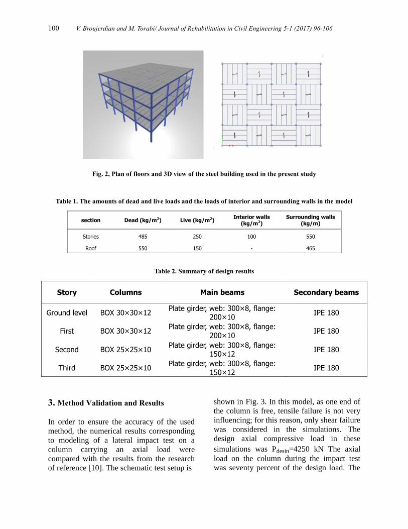
A 4-story building with intermediate moment
resisting frames in both x- and y-directions is
considered (Fig. 2). The building has a
similar plan in all stories and the height of its
stories is 3.2 m. Beam to column connections
is rigid and the connection of columns to the
foundation is of fixed type. The structure
floors are assumed of deck with composite
beams. The consumed steel is ST-37 steel
with the ultimate strength of 3700 kg/cm2
and yield strength of 2400 kg/cm2. The
structural design was performed by ETABS
2015 software in accordance with the tenth
chapter of Iranian National Building Code
[22]. Under the effects of dead, live, and
earthquake loads computed based on the
sixth chapter of afore mentioned Code.
The amounts of dead and live loads, and the
loads of interior and surrounding walls are
presented in table 1. Earthquake loads were
calculated with the assumption that the
structure is located in Tehran. The soil under
the foundation is assumed to be of type II.
For the sake of simplicity and to avoid the
need for several sections, the elements were
categorized fore group designing. Then to
obtain an economic design, the minimum
required section is selected for each group.
The design is performed according to LRFD-
method. The obtained design sections are
summarized in table 2.
(a) (b) (c)
100 V. Broujerdian and M. Torabi/ Journal of Rehabilitation in Civil Engineering 5-1 (2017) 96-106
Fig. 2, Plan of floors and 3D view of the steel building used in the present study
Table 1. The amounts of dead and live loads and the loads of interior and surrounding walls in the model
section Dead (kg/m2) Live (kg/m2) Interior walls
(kg/m2) Surrounding walls
(kg/m)
Stories 485 250 100 550
Roof 550 150 - 465
Table 2. Summary of design results
Story Columns Main beams Secondary beams
Ground level BOX 30×30×12 Plate girder, web: 300×8, flange:
200×10 IPE 180
First BOX 30×30×12 Plate girder, web: 300×8, flange:
200×10 IPE 180
Second BOX 25×25×10 Plate girder, web: 300×8, flange:
150×12 IPE 180
Third BOX 25×25×10 Plate girder, web: 300×8, flange:
150×12 IPE 180
3. Method Validation and Results
In order to ensure the accuracy of the used
method, the numerical results corresponding
to modeling of a lateral impact test on a
column carrying an axial load were
compared with the results from the research
of reference [10]. The schematic test setup is
shown in Fig. 3. In this model, as one end of
the column is free, tensile failure is not very
influencing; for this reason, only shear failure
was considered in the simulations. The
design axial compressive load in these
simulations was Pdesin=4250 kN The axial
load on the column during the impact test
was seventy percent of the design load. The
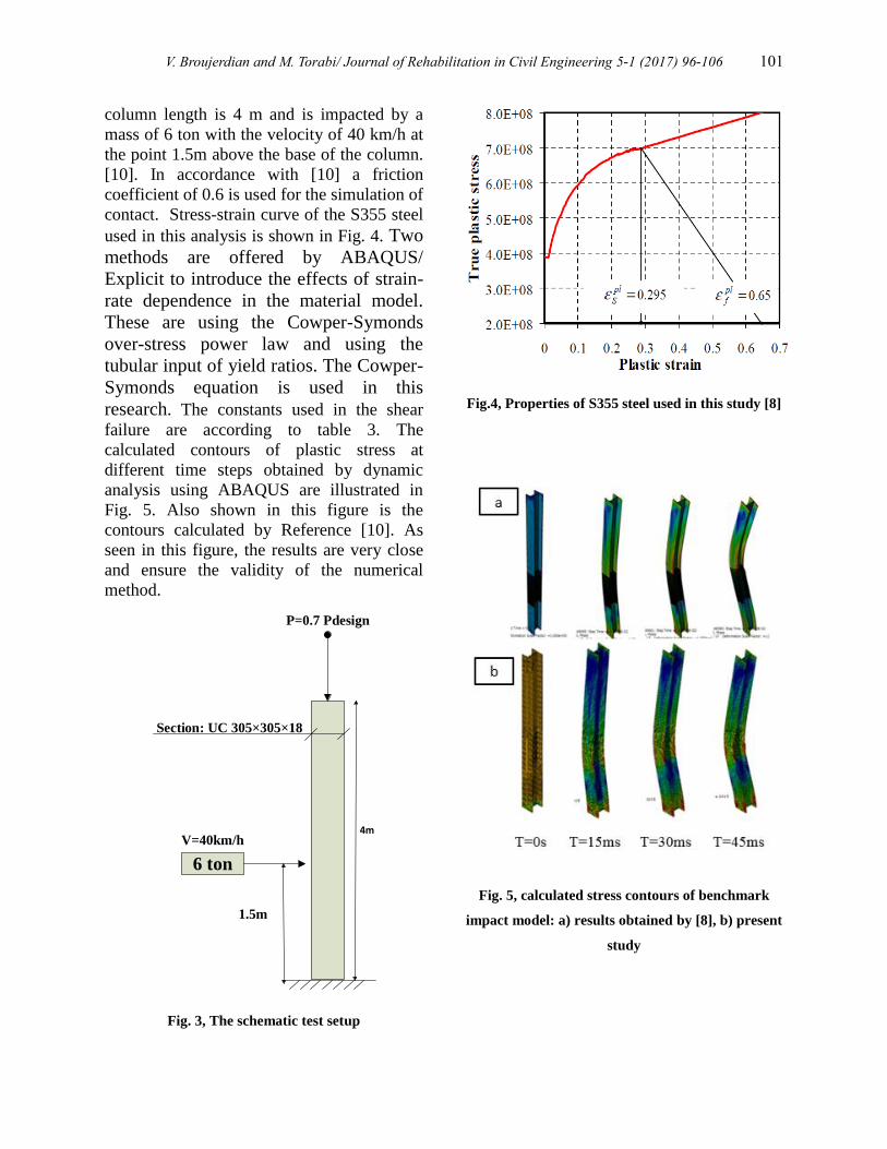
V. Broujerdian and M. Torabi/ Journal of Rehabilitation in Civil Engineering 5-1 (2017) 96-106 101
column length is 4 m and is impacted by a
mass of 6 ton with the velocity of 40 km/h at
the point 1.5m above the base of the column.
[10]. In accordance with [10] a friction
coefficient of 0.6 is used for the simulation of
contact. Stress-strain curve of the S355 steel
used in this analysis is shown in Fig. 4. Two
methods are offered by ABAQUS/
Explicit to introduce the effects of strain-
rate dependence in the material model.
These are using the Cowper-Symonds
over-stress power law and using the
tubular input of yield ratios. The Cowper-
Symonds equation is used in this
research. The constants used in the shear
failure are according to table 3. The
calculated contours of plastic stress at
different time steps obtained by dynamic
analysis using ABAQUS are illustrated in
Fig. 5. Also shown in this figure is the
contours calculated by Reference [10]. As
seen in this figure, the results are very close
and ensure the validity of the numerical
method.
6 ton
V=40km/h
1.5m
Section: UC 305×305×18
P=0.7 Pdesign
4m
Fig. 3, The schematic test setup
Fig.4, Properties of S355 steel used in this study [8]
Fig. 5, calculated stress contours of benchmark
impact model: a) results obtained by [8], b) present
study
102 V. Broujerdian and M. Torabi/ Journal of Rehabilitation in Civil Engineering 5-1 (2017) 96-106
Table 3. Properties of shear failure of S355 steel used in this study [8]
Plastic strain at
damage initiation
Maximum shear
stress ratio
Maximum strain
rate (sec-1
) 𝜀𝑓𝑝𝑙
𝑢𝑓𝑝𝑙(𝑚)
0.0065 0.65 16.5 1.85 0.295
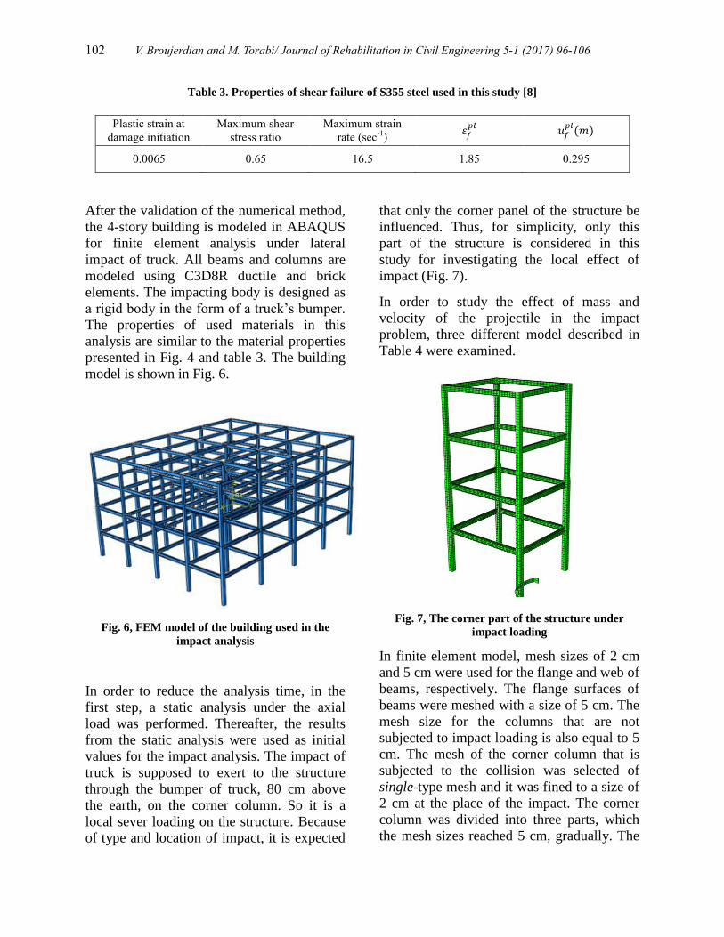
After the validation of the numerical method,
the 4-story building is modeled in ABAQUS
for finite element analysis under lateral
impact of truck. All beams and columns are
modeled using C3D8R ductile and brick
elements. The impacting body is designed as
a rigid body in the form of a truck’s bumper.
The properties of used materials in this
analysis are similar to the material properties
presented in Fig. 4 and table 3. The building
model is shown in Fig. 6.
Fig. 6, FEM model of the building used in the
impact analysis
In order to reduce the analysis time, in the
first step, a static analysis under the axial
load was performed. Thereafter, the results
from the static analysis were used as initial
values for the impact analysis. The impact of
truck is supposed to exert to the structure
through the bumper of truck, 80 cm above
the earth, on the corner column. So it is a
local sever loading on the structure. Because
of type and location of impact, it is expected
that only the corner panel of the structure be
influenced. Thus, for simplicity, only this
part of the structure is considered in this
study for investigating the local effect of
impact (Fig. 7).
In order to study the effect of mass and
velocity of the projectile in the impact
problem, three different model described in
Table 4 were examined.
Fig. 7, The corner part of the structure under
impact loading
In finite element model, mesh sizes of 2 cm
and 5 cm were used for the flange and web of
beams, respectively. The flange surfaces of
beams were meshed with a size of 5 cm. The
mesh size for the columns that are not
subjected to impact loading is also equal to 5
cm. The mesh of the corner column that is
subjected to the collision was selected of
single-type mesh and it was fined to a size of
2 cm at the place of the impact. The corner
column was divided into three parts, which
the mesh sizes reached 5 cm, gradually. The
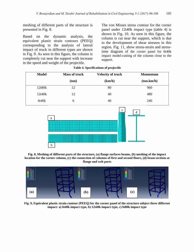
V. Broujerdian and M. Torabi/ Journal of Rehabilitation in Civil Engineering 5-1 (2017) 96-106 103
meshing of different parts of the structure is
presented in Fig. 8.
Based on the dynamic analysis, the
equivalent plastic strain contours (PEEQ)
corresponding to the analysis of lateral
impact of truck in different types are shown
in Fig. 9. As seen in this figure, the column is
completely cut near the support with increase
in the speed and weight of the projectile.
The von Misses stress contour for the corner
panel under 12t40k impact type (table 4) is
shown in Fig. 10. As seen in this figure, the
column is cut near the support, which is due
to the development of shear stresses in this
region. Fig. 11, show stress-strain and stress-
time diagram of the corner panel for 6t40k
impact model-cutting of the column close to the
support.
Table 4. Specifications of projectile
Model Mass of truck
(ton)
Velocity of truck
(km/h)
Momentum
(ton.km/h)
12t80k 12 80 960
12t40k 12 40 480
6t40k 6 40 240
Fig. 8, Meshing of different parts of the structure, (a) flange surfaces beams, (b) meshing of the impact
location for the corner column, (c) the connection of columns of first and second floors, (d) beam sections at
flange and web parts
Fig. 9, Equivalent plastic strain contour (PEEQ) for the corner panel of the structure subject three different
impact: a) 6t40k impact type, b) 12t40k impact type, c) 6t80k impact type
(a) (b) (c)
104 V. Broujerdian and M. Torabi/ Journal of Rehabilitation in Civil Engineering 5-1 (2017) 96-106
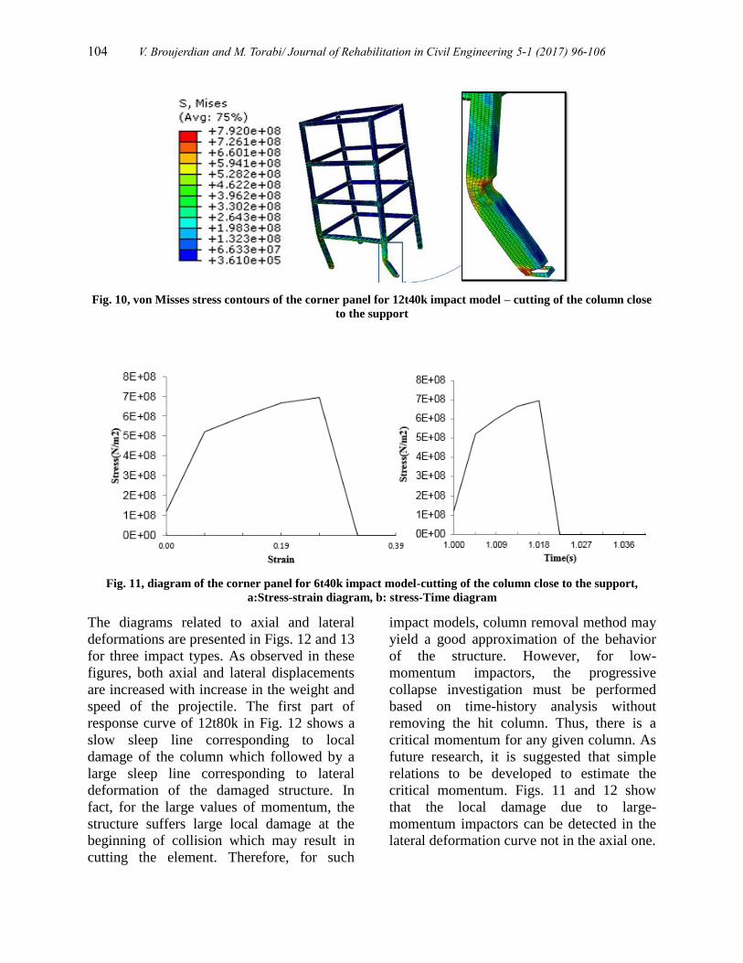
Fig. 10, von Misses stress contours of the corner panel for 12t40k impact model – cutting of the column close
to the support
Fig. 11, diagram of the corner panel for 6t40k impact model-cutting of the column close to the support,
a:Stress-strain diagram, b: stress-Time diagram
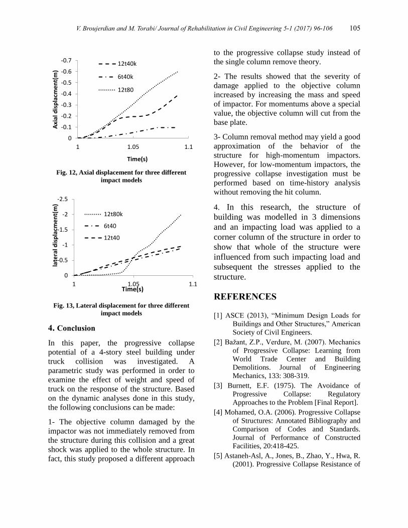
The diagrams related to axial and lateral
deformations are presented in Figs. 12 and 13
for three impact types. As observed in these
figures, both axial and lateral displacements
are increased with increase in the weight and
speed of the projectile. The first part of
response curve of 12t80k in Fig. 12 shows a
slow sleep line corresponding to local
damage of the column which followed by a
large sleep line corresponding to lateral
deformation of the damaged structure. In
fact, for the large values of momentum, the
structure suffers large local damage at the
beginning of collision which may result in
cutting the element. Therefore, for such
impact models, column removal method may
yield a good approximation of the behavior
of the structure. However, for low-
momentum impactors, the progressive
collapse investigation must be performed
based on time-history analysis without
removing the hit column. Thus, there is a
critical momentum for any given column. As
future research, it is suggested that simple
relations to be developed to estimate the
critical momentum. Figs. 11 and 12 show
that the local damage due to large-
momentum impactors can be detected in the
lateral deformation curve not in the axial one.
V. Broujerdian and M. Torabi/ Journal of Rehabilitation in Civil Engineering 5-1 (2017) 96-106 105
Fig. 12, Axial displacement for three different
impact models
Fig. 13, Lateral displacement for three different
impact models
4. Conclusion
In this paper, the progressive collapse
potential of a 4-story steel building under
truck collision was investigated. A
parametric study was performed in order to
examine the effect of weight and speed of
truck on the response of the structure. Based
on the dynamic analyses done in this study,
the following conclusions can be made:
1- The objective column damaged by the
impactor was not immediately removed from
the structure during this collision and a great
shock was applied to the whole structure. In
fact, this study proposed a different approach
to the progressive collapse study instead of
the single column remove theory.
2- The results showed that the severity of
damage applied to the objective column
increased by increasing the mass and speed
of impactor. For momentums above a special
value, the objective column will cut from the
base plate.
3- Column removal method may yield a good
approximation of the behavior of the
structure for high-momentum impactors.
However, for low-momentum impactors, the
progressive collapse investigation must be
performed based on time-history analysis
without removing the hit column.
4. In this research, the structure of
building was modelled in 3 dimensions
and an impacting load was applied to a
corner column of the structure in order to
show that whole of the structure were
influenced from such impacting load and
subsequent the stresses applied to the
structure.
REFERENCES
[1] ASCE (2013), “Minimum Design Loads for
Buildings and Other Structures,” American
Society of Civil Engineers.
[2] Bažant, Z.P., Verdure, M. (2007). Mechanics
of Progressive Collapse: Learning from
World Trade Center and Building
Demolitions. Journal of Engineering
Mechanics, 133: 308-319.
[3] Burnett, E.F. (1975). The Avoidance of
Progressive Collapse: Regulatory
Approaches to the Problem [Final Report].
[4] Mohamed, O.A. (2006). Progressive Collapse
of Structures: Annotated Bibliography and
Comparison of Codes and Standards.
Journal of Performance of Constructed
Facilities, 20:418-425.
[5] Astaneh-Asl, A., Jones, B., Zhao, Y., Hwa, R.
(2001). Progressive Collapse Resistance of
-0.7
-0.6
-0.5
-0.4
-0.3
-0.2
-0.1
0
1 1.05 1.1
Axi
al d
isp
lacm
en
t(m
)
Time(s)
12t40k
6t40k
12t80
-2.5
-2
-1.5
-1
-0.5
0
1 1.05 1.1
late
ral d
isp
lacm
en
t(m
)
Time(s)
12t80k
6t40
12t40
106 V. Broujerdian and M. Torabi/ Journal of Rehabilitation in Civil Engineering 5-1 (2017) 96-106
Steel Building Floors. Report Number
UCB/CEE-Steel-2001.
[6] Grierson, D. E., Xu, L., & Liu, Y. (2005).
Progressive‐failure analysis of buildings
subjected to abnormal loading. Computer‐Aided Civil and Infrastructure
Engineering, 20(3), 155-171.
[7] Kaewkulchai, G., Williamson, E.B. (2004).
Beam Element Formulation and Solution
Procedure for Dynamic Progressive
Collapse Analysis. Computers &
Structures, 639-651.
[8] Khandelwal, K., El-Tawil, S., Sadek, F.
(2009). Progressive Collapse Analysis of
Seismically Designed Steel Braced
Frames. Journal of Constructional Steel
Research, 65:699-708.
[9] Khandelwal, K., & El-Tawil, S. (2011).
Pushdown resistance as a measure of
robustness in progressive collapse analysis.
Engineering Structures, 33(9), 2653-2661.
[10] Al-Thairy, H.A., Wang Y.C. (2014).
Behaviour and design of steel columns
subjected to vehicle impact. Trans Tech
Publications, 193-198.
[11] Alam, M.I., Fawzia, S. (2015). Numerical
studies on CFRP strengthened steel
columns under transverse impact.
Composite Structures, 428-441.
[12] Yousuf, M., Uy, B., Tao, Z., Remennikov,
A., Liew, J.R. (2013). Transverse impact
resistance of hollow and concrete filled
stainless steel columns. Journal of
Constructional Steel Research, 177-189.
[13] Makarem, F.S., Abed, F. (2013) Nonlinear
finite element modeling of dynamic
localizations in high strength steel columns
under impact. International Journal of
Impact Engineering, 47-61.
[14] Ari-Gur, J., Weller, T., Singer, J. (1982).
Experimental and theoretical studies of
columns under axial impact. International
Journal of Solids and Structures, 619-641
[15] Menkes, S. B., & Opat, H. J. (1973). Broken
beams. Experimental Mechanics, 13(11),
480-486.
[16] Chen, F. L., & Yu, T. X. (2000). Influence
of axial pre-load on plastic failure of
beams subjected to transverse dynamic
load. In Key Engineering Materials (Vol.
177, pp. 255-260).
[17] Yu, J., & Jones, N. (1989). Numerical
simulation of a clamped beam under
impact loading. Computers & structures,
32(2), 281-293.
[18] Jilin, Y., & Norman, J. (1991). Further
experimental investigations on the failure
of clamped beams under impact loads.
International Journal of Solids and
Structures, 27(9), 1113-1137.
[19] Yu, J.L. & JONES, N. (1997). Numerical
simulation of impact loaded steel beams
and the failure criteria. International
Journal of Solids and Structures. 34, 3977-
4004
[20] Mannan, M. N., Ansari, R., & Abbas, H.
(2008). Failure of aluminium beams under
low velocity impact. International Journal
of Impact Engineering, 35(11), 1201-1212.
[21] Bambach, M.R., JAMA, H., ZHAO, X. L. &
GRZEBIETA, R. H. (2008). Hollow and
concrete filled steel hollow sections under
transverse impact loads. Engineering
Structures, 30, 2859-2870
[22] INBC 10 (1392). Design and construction of
steel structures in Iran. Building and House
Research Center, Tehran, Iran.
Related Documents