1 Progressive Collapse of Multi-Storey Buildings due to Sudden Column Loss – Part II: Application A.G. Vlassis 1 , B.A. Izzuddin 2 , A.Y. Elghazouli 3 , D.A. Nethercot 4 ABSTRACT The companion paper presents the principles of a new design-oriented methodology for progressive collapse assessment of multi-storey buildings. The proposed procedure, which can be implemented at various levels of structural idealisation, determines ductility demand and supply in assessing the potential for progressive collapse initiated by instantaneous loss of a vertical support member. This paper demonstrates the applicability of the proposed approach by means of a case study, which considers sudden removal of a ground floor column in a typical steel-framed composite building. In line with current progressive collapse guidelines for buildings with a relatively simple and repetitive layout, the two principal scenarios investigated include removal of a peripheral column and a corner column. The study shows that such structures can be prone to progressive collapse, especially due to failure of the internal secondary beam support joints to safely transfer the gravity loads to the surrounding undamaged members if a flexible fin plate joint detail is employed. The provision of additional reinforcement in the slab over the hogging moment regions can generally have a beneficial effect on both the dynamic load carrying and deformation capacities. The response can be further improved if axial restraint provided by the adjacent structure can be relied upon. The study also highlights the inability of bare-steel beams to survive column removal despite satisfaction of the code prescribed structural integrity provisions. This demonstrates that tying force requirements alone cannot always guarantee structural robustness without explicit consideration of ductility demand/supply in the support joints of the affected members, as determined by their nonlinear dynamic response. Keywords: progressive collapse, column removal, composite joints, ductility, steel-framed buildings 1 Former research student, Department of Civil and Environmental Engineering, Imperial College London SW7 2AZ, [email protected] 2 Professor of Computational Structural Mechanics, Department of Civil and Environmental Engineering, Imperial College London SW7 2AZ, [email protected] 3 Reader in Engineering Structures, Department of Civil and Environmental Engineering, Imperial College London SW7 2AZ, [email protected] 4 Professor of Civil Engineering, Department of Civil and Environmental Engineering, Imperial College London SW7 2AZ, [email protected]

Welcome message from author
This document is posted to help you gain knowledge. Please leave a comment to let me know what you think about it! Share it to your friends and learn new things together.
Transcript
1
Progressive Collapse of Multi-Storey Buildings
due to Sudden Column Loss – Part II: Application
A.G. Vlassis1, B.A. Izzuddin
2, A.Y. Elghazouli
3, D.A. Nethercot
4
ABSTRACT
The companion paper presents the principles of a new design-oriented methodology for progressive
collapse assessment of multi-storey buildings. The proposed procedure, which can be implemented at
various levels of structural idealisation, determines ductility demand and supply in assessing the
potential for progressive collapse initiated by instantaneous loss of a vertical support member. This
paper demonstrates the applicability of the proposed approach by means of a case study, which
considers sudden removal of a ground floor column in a typical steel-framed composite building. In
line with current progressive collapse guidelines for buildings with a relatively simple and repetitive
layout, the two principal scenarios investigated include removal of a peripheral column and a corner
column. The study shows that such structures can be prone to progressive collapse, especially due to
failure of the internal secondary beam support joints to safely transfer the gravity loads to the
surrounding undamaged members if a flexible fin plate joint detail is employed. The provision of
additional reinforcement in the slab over the hogging moment regions can generally have a beneficial
effect on both the dynamic load carrying and deformation capacities. The response can be further
improved if axial restraint provided by the adjacent structure can be relied upon. The study also
highlights the inability of bare-steel beams to survive column removal despite satisfaction of the code
prescribed structural integrity provisions. This demonstrates that tying force requirements alone cannot
always guarantee structural robustness without explicit consideration of ductility demand/supply in the
support joints of the affected members, as determined by their nonlinear dynamic response.
Keywords: progressive collapse, column removal, composite joints, ductility, steel-framed buildings
1 Former research student, Department of Civil and Environmental Engineering, Imperial College London SW7
2AZ, [email protected] 2 Professor of Computational Structural Mechanics, Department of Civil and Environmental Engineering,
Imperial College London SW7 2AZ, [email protected] 3 Reader in Engineering Structures, Department of Civil and Environmental Engineering, Imperial College
London SW7 2AZ, [email protected] 4 Professor of Civil Engineering, Department of Civil and Environmental Engineering, Imperial College London
SW7 2AZ, [email protected]

2
1. Introduction
A new relatively simple yet sufficiently accurate methodology is presented in the companion
paper[1]
, which aims at appraising the efficacy of multi-storey buildings to resist progressive
collapse triggered by sudden local column failure, as a consequence of an extreme loading
event. The potential for progressive collapse is assessed in three independent stages based on
the ductility demand and supply in the critical regions of the affected structural members. A
significant advantage of the developed procedure is that it can explicitly account for the
dynamic effects associated with the instantaneous column removal through a simplified
energy equivalence approach, thus avoiding the need for nonlinear dynamic analysis. With
respect to its applicability, the proposed method accommodates both simplified and detailed
models of the nonlinear static response. Moreover, it can be implemented at various levels of
structural idealisation, depending on the required level of sophistication, the feasibility of
model reduction and the availability of analytical tools[1]
. These levels correspond to either
the full structure, excluding the damaged column, or critical sub-structures in which ductility
demands are concentrated.
The components of the developed methodology are implemented in this paper to assess the
susceptibility of a typical seven-storey steel-framed composite building to progressive
collapse initiated by instantaneous loss of a ground floor column. Since the building has a
relatively simple, uniform and repetitive layout without underground parking or uncontrolled
public ground floor areas, assessment is based on the investigation of two principal scenarios:
i) removal of a peripheral column, and ii) removal of a corner column. The lowest level of
structural idealisation discussed in the companion paper[1]
is employed when determining the
ductility demand and supply in the support joints of the individual members directly
associated with the removed columns. Subsequently, a grillage-type approximation is used to
establish the overall dynamic resistance of a typical floor plate at the next level of idealisation
accounting for coupling effects on the basis of an assumed deformation mode.
Application of the proposed methodology demonstrates that structures of this type can be
vulnerable to progressive collapse triggered by sudden loss of a vertical support member,
mainly due to the inability of internal secondary beam support joints to transfer the gravity
loads to the adjacent undamaged parts of the structure. Moreover, the study highlights the
necessity to rationalise progressive collapse assessment through explicit consideration of the
nonlinear dynamic response and ductility demand/supply in the support joints of the affected
3
members, since the code prescribed tying force requirements alone are not always capable of
precluding progressive collapse. The benefits of additional reinforcement in the slab over the
connections when composite joint details are used as well as the effects of axial restraint
provided by the adjacent members towards improving structural robustness are also
thoroughly examined and practical recommendations are made.
2. Overview of Case Study
This section is concerned with the most important features of the example structure in relation
to the three assessment stages required by the proposed methodology[1]
. In this respect, the
adopted structural system is first briefly described, while the selected assessment strategy and
the corresponding level of structural idealisation are subsequently defined.
2.1. Structural Configuration
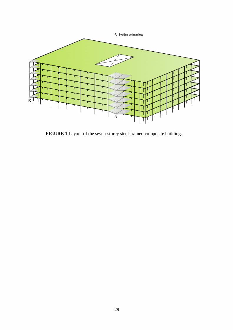
A typical seven-storey steel-framed composite building designed for office use is studied to
demonstrate application of the proposed progressive collapse assessment method. The layout
of the building as well as the location of the removed ground floor columns are shown in Fig.
1. The general configuration of the superstructure is based on a 9m × 9m structural grid with a
central atrium space, which commences at the ground floor. The building is designed as
simple construction, according to current UK steel design practice, and thus the required
lateral resistance is provided by a pair of similarly sized braced cores. A conventional
composite steel and concrete construction is selected for the superstructure floors to expedite
erection and minimize column and foundation loads. All floors are designed to carry equal
gravity loads. The values of the unfactored dead loads (DL) and imposed loads (IL) on each
floor are 4.2kN/m2 and 5.0kN/m
2, respectively. Furthermore, in addition to the floor loads, the
edge beams in both directions of the building carry a façade load of 8.3kN/m.
Although the steel beams are designed to act compositely with the slabs, simple rather than
composite joint details are used throughout the structure. Joint design and detailing are carried
out in accordance with current UK design guidelines[2]
. Partial depth flexible end-plate
connections are mainly employed for the beam-to-column joints, while fin plate is the
predominant connection type for the beam-to-beam joints. With respect to structural integrity,
the tying force requirements specified in §2.4.5 of BS 5950: Part 1[3]
have been satisfied for
the end joints of the beams in both the longitudinal and the transverse directions of the
building.
4
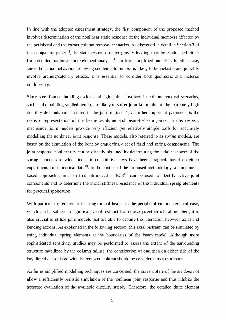
2.2. Progressive Collapse Assessment Approach
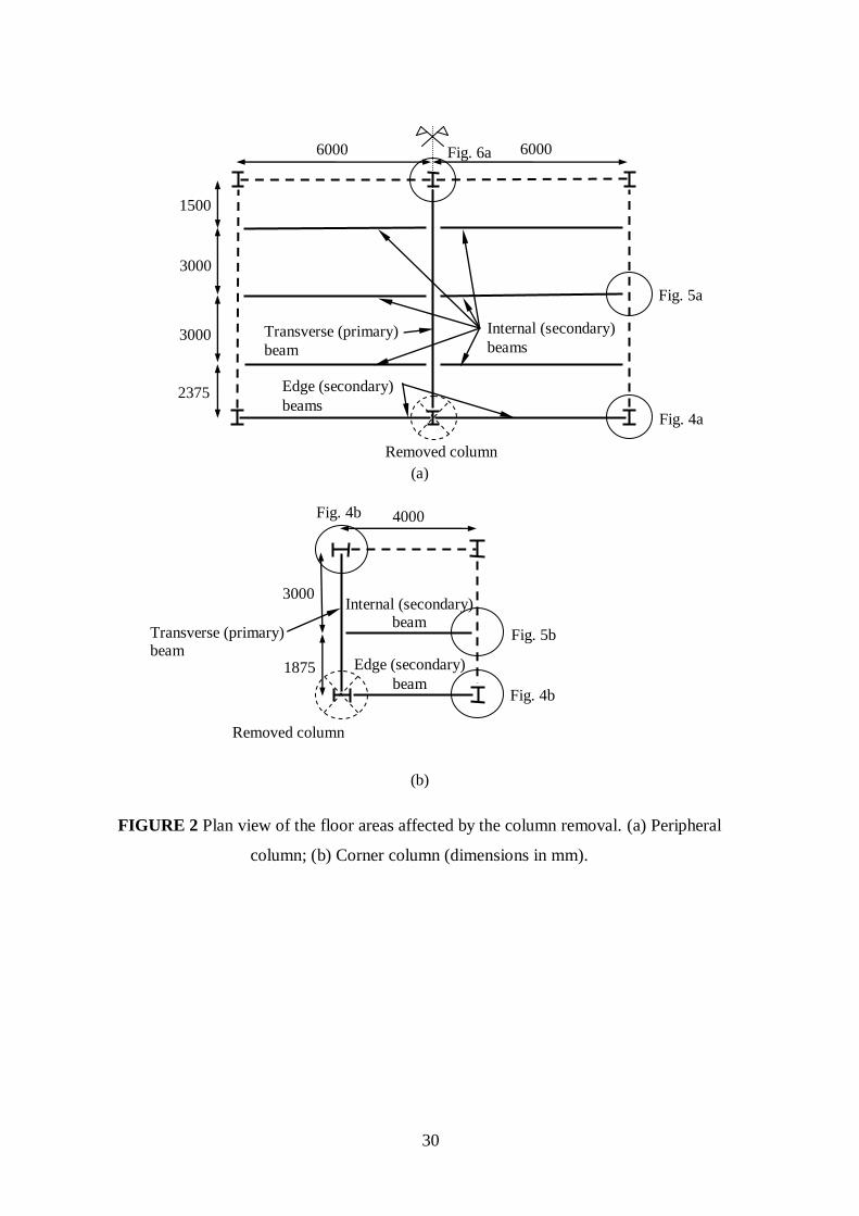
The geometry of the two floor areas directly affected by the sudden removal of the peripheral
and the corner columns is given in Figs. 2a and 2b, respectively. To roughly appraise the
susceptibility of the structure to progressive collapse as a consequence of the local column
failure as well as to obtain an insight of the relative contribution of the components within
each system, the lowest level of model reduction, as introduced in the companion paper[1]
, is
initially considered. At this level, the pseudo-static responses of the individual members,
including the edge and internal secondary beams in the longitudinal direction as well as the
transverse primary beams (Figs. 2a-b), are established from their nonlinear static responses
using the newly developed simplified dynamic assessment approach[1]
. Subsequently, in order
to perform a more realistic assessment that takes into account three dimensional effects due to
coupling, a grillage-type approximation, at the next level of idealisation, is employed to
determine the overall dynamic resistance of the two floor systems by assembling the pseudo-
static responses of individual members based on the simplified procedure described in
Sections 3.2.2 and 4.1 and verified in Appendix B of the companion paper[1]
. This is achieved
by assuming a dominant deformation mode, which should be subject to a limiting deformation
profile that is determined by the ductility supply of one or more critical components. The
calculated pseudo-static capacity, accounting for ductility supply, should then be compared to
the demand imposed by the gravity loads in each case to assess the potential of the structure
for progressive collapse.
It should be noted that, in the context of the adopted strategy, detailed slab modelling, which
can enhance response by accounting for planar membrane action, is not considered.
Moreover, higher-level idealisations need not be taken into account given that the various
affected floor plates are identical in terms of structure and loading, rendering the load sharing
along the line of the damaged column negligible. Furthermore, as can be easily verified, the
surrounding columns have sufficient strength to sustain the redistributed load due to column
removal in both scenarios considered.
3. Modelling Techniques
The modelling techniques and the associated assumptions used to determine the nonlinear
static response of the affected members are discussed in this section. Since ductility demands
are concentrated in the support joints, particular emphasis is given to the mechanical models
used to simulate joint behaviour under combined bending and axial actions.
5
In line with the adopted assessment strategy, the first component of the proposed method
involves determination of the nonlinear static response of the individual members affected by
the peripheral and the corner column removal scenarios. As discussed in detail in Section 3 of
the companion paper[1]
, the static response under gravity loading may be established either
from detailed nonlinear finite element analysis[4,5]
or from simplified models[6]
. In either case,
since the actual behaviour following sudden column loss is likely to be inelastic and possibly
involve arching/catenary effects, it is essential to consider both geometric and material
nonlinearity.
Since steel-framed buildings with semi-rigid joints involved in column removal scenarios,
such as the building studied herein, are likely to suffer joint failure due to the extremely high
ductility demands concentrated in the joint regions [7]
, a further important parameter is the
realistic representation of the beam-to-column and beam-to-beam joints. In this respect,
mechanical joint models provide very efficient yet relatively simple tools for accurately
modelling the nonlinear joint response. These models, also referred to as spring models, are
based on the simulation of the joint by employing a set of rigid and spring components. The
joint response nonlinearity can be directly obtained by determining the axial response of the
spring elements to which inelastic constitutive laws have been assigned, based on either
experimental or numerical data[8]
. In the context of the proposed methodology, a component-
based approach similar to that introduced in EC3[9]
can be used to identify active joint
components and to determine the initial stiffness/resistance of the individual spring elements
for practical application.
With particular reference to the longitudinal beams in the peripheral column removal case,
which can be subject to significant axial restraint from the adjacent structural members, it is
also crucial to utilize joint models that are able to capture the interaction between axial and
bending actions. As explained in the following section, this axial restraint can be simulated by
using individual spring elements at the boundaries of the beam model. Although more
sophisticated sensitivity studies may be performed to assess the extent of the surrounding
structure mobilized by the column failure, the contribution of one span on either side of the
bay directly associated with the removed column should be considered as a minimum.
As far as simplified modelling techniques are concerned, the current state of the art does not
allow a sufficiently realistic simulation of the nonlinear joint response and thus inhibits the
accurate evaluation of the available ductility supply. Therefore, the detailed finite element
6
modelling approach with mechanical joint models is adopted in this case study to obtain the
nonlinear static responses of the individual members at the lowest level of idealisation.
However, as noted above, in order to demonstrate the applicability and practicality of the
proposed methodology, the response at the next floor plate level of idealisation is established
from a simplified assembly procedure based on a dominant deformation mode.
3.1. Beam Modelling
The structural member sizes of the affected steel beams in both cases are given in Table 1.
With regard to the concrete „flange‟, the total slab thickness is 130mm assumed cast on metal
decking with a dovetail profile. Only the concrete area above the top of the ribs is taken into
account for developing the beam models, resulting in a concrete „flange‟ thickness of 70mm,
and the effective width values are calculated in accordance with the EC4 provisions[10]
. The
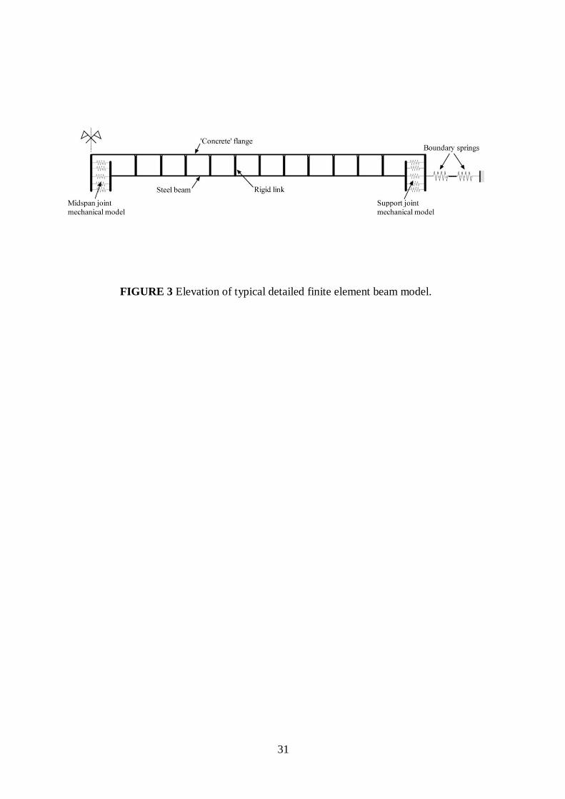
material properties are summarized in Table 2. Cubic elasto-plastic beam-column elements,
that can capture both geometric and material nonlinearities, are used to model the steel beam
and the concrete „flange‟[11]
. As required by EC4[10]
for the hogging moment regions of
composite beams, full shear connection between the concrete slab on metal decking and the
steel beam is assumed and, hence, composite action is realised by interconnecting the
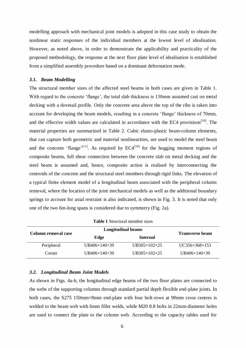
centroids of the concrete and the structural steel members through rigid links. The elevation of
a typical finite element model of a longitudinal beam associated with the peripheral column
removal, where the location of the joint mechanical models as well as the additional boundary
springs to account for axial restraint is also indicated, is shown in Fig. 3. It is noted that only
one of the two 6m-long spans is considered due to symmetry (Fig. 2a).
Table 1 Structural member sizes
Column removal case Longitudinal beams
Transverse beam Edge Internal
Peripheral UB406×140×39 UB305×102×25 UC356×368×153
Corner UB406×140×39 UB305×102×25 UB406×140×39
3.2. Longitudinal Beam Joint Models
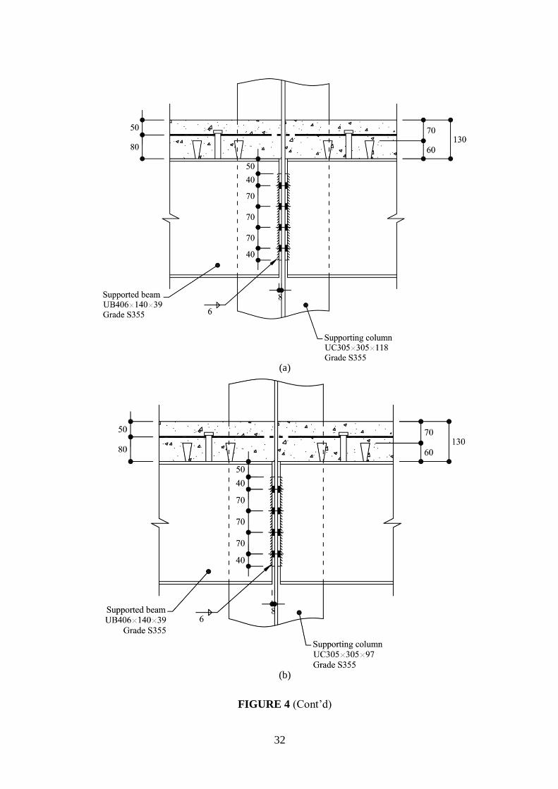
As shown in Figs. 4a-b, the longitudinal edge beams of the two floor plates are connected to
the webs of the supporting columns through standard partial depth flexible end-plate joints. In
both cases, the S275 150mm×8mm end-plate with four bolt-rows at 90mm cross centres is
welded to the beam web with 6mm fillet welds, while M20 8.8 bolts in 22mm-diameter holes
are used to connect the plate to the column web. According to the capacity tables used for

7
joint design[2]
, the joint has a shear capacity of 356kN and a tying capacity of 224kN
governed by shear in the beam web and the tensile capacity of the end-plate, respectively.
Figure 4c shows the mechanical model that is developed to simulate joint behaviour. This
consists of a set of two rigid links and six spring components. The four inner springs at 70mm
centres are used to replicate the axial response of the four bolt-rows, where a bilinear response
with 1% strain-hardening and a rigid-hardening-plastic response are assumed respectively in
tension and compression. The initial tensile stiffness and the resistance at yield of each bolt-
row have been calculated based on the EC3 component method[9]
. The resistance of the bolt-
rows in compression is governed by the crushing strength of the supported beam web, with a
20% overstrength factor assumed due to strain-hardening. The outermost springs utilize a gap-
contact rigid-plastic curve to model the gap between the steel beam and the column web with
the plastic limit taken as the crushing resistance of the beam flange/web in compression,
increased by 20% to account for strain-hardening. Moreover, the bottom spring provides shear
resistance assuming a rigid-plastic shear response, where the plastic limit is set equal to the
shear capacity of the joint.
Table 2 Material properties
Material Grade Elastic modulus
(GPa) Strength (MPa)
Strain-hardening
factor (%)
Structural steel S355 210 355 1.0
Concrete C30 (lightweight) 27.3 30 -
Reinforcement Type 2 high yield 200 460 1.0
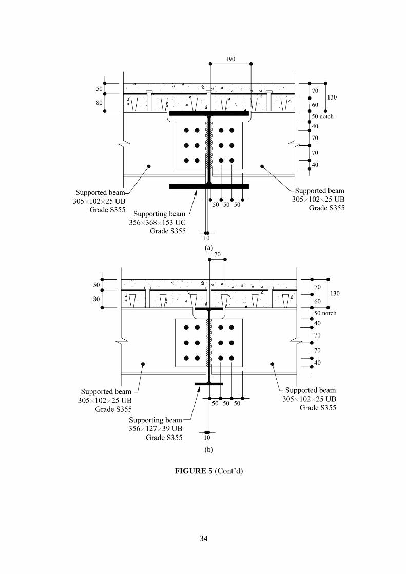
Fin plate joint details are employed to connect the internal secondary beams to the
transversely spanning primary beams for both the peripheral (Fig. 5a) and the corner (Fig. 5b)
column removal cases. The details consist of an S275 150mm×10mm plate with a double
vertical line of three bolt-rows. The plate is welded to the supporting beam web with two
8mm fillet welds and bolted to the supported beam web with six M20 8.8 bolts in 22mm-
diameter holes. The joint has a shear capacity of 160kN governed by the capacity at the
notched section of the supported beam, while the tying capacity is 317kN associated with the
tensile capacity of the beam web[2]
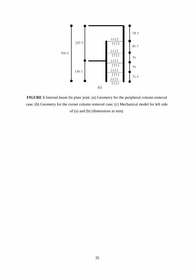
. As illustrated in Fig. 5c, the joint mechanical model
comprises two rigid links and five spring components. Identical joint behaviour in tension and
compression is assumed and, thus, a symmetric bilinear curve with 1% strain-hardening is
assigned to the three inner springs simulating the axial response of the three bolt-rows. It is

8
noted that the EC3 provisions[9]
are not directly applicable to fin plate joints and, hence they
have been combined with current UK design guidelines[2]
to determine the spring properties.
The two extreme springs are located at the top and bottom flanges of the supported beam to
represent a gap-contact response, while the bottom spring also provides shear resistance,
similar to the flexible end-plate connection.
As shown in Fig. 3, to consider catenary effects due to axial restraint provided by the
neighbouring structural members in the case of the peripheral column removal, two spring
elements in series are attached to the end of the edge and internal longitudinal beam models,
representing axial response of the connection on the opposite side of the support joint, which
as shown in Figs. 4a and 5a is identical to that under consideration, and that of the adjacent
beam, respectively. Since strength is governed by the joint mechanical models described in
the previous paragraphs, linear springs can be used to simulate the restraint provided by the
surrounding structure.
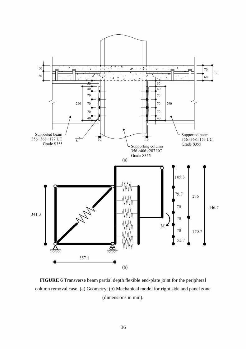
3.3. Transverse Beam Joint Models
The transverse primary beam in the peripheral column removal case is connected to the flange
of the supporting column through a partial depth flexible end-plate joint. Apart from
employing a 10mm-thick end-plate and 8mm instead of 6mm fillet welds due to the
significantly higher design shear force transferred from the supported beam, joint detailing is
otherwise identical to that of the end joints of the edge beams (Fig. 6a). The shear capacity of
the joint is 675kN governed by the strength of the fillet welds, while the tying capacity is
equal to 438kN limited by the tensile capacity of the end-plate[2]
. Since the transverse beam
exhibits cantilever beam action upon column removal and thus is axially unrestrained, the
mechanical model of Fig. 6b can be used to replicate the joint behaviour under pure bending.
Similar to the joint models of the longitudinal edge beams, a bilinear response with 1% strain-
hardening and a rigid-hardening-plastic response are respectively assumed in tension and
compression for the four inner springs corresponding to the four bolt-rows. In the latter case, a
20% overstrength due to strain-hardening is again considered. Furthermore, the two outermost
springs, which simulate the gap between the beam and the column flange, use a gap-contact
rigid-plastic curve, where the plastic limit is taken as the minimum resistance of the column
web and the beam flange\web in compression, where the latter is increased by 20% to take
strain-hardening into account. Again, shear resistance is provided by the lower spring through
a rigid-plastic shear response curve. Since the support joint of the transverse primary beam is
a major axis configuration, the column web panel in shear is also modelled using rigid
9
boundaries with pinned ends (Fig. 6b). An elastic-perfectly plastic spring component is used
to represent the response of the panel zone, where the initial stiffness and the yield limit are
calculated according to the EC3 component method[9]
.
The support joint detail of the transverse primary beam in the corner column removal case is
identical to that of the longitudinal edge beam (Fig. 4b). Therefore, since the sizes of the
connected members are also identical, the mechanical model of Fig. 4c can be employed to
simulate joint behaviour under bending due to cantilever action of the transverse beam
following column removal.
4. Joint Failure Criteria
In order to assess the potential for progressive collapse, the estimated joint ductility demand,
resulting from application of the first two stages of the proposed methodology, should be
compared to the available joint ductility supply. The latter can be estimated through the
introduction of joint failure criteria that explicitly account for the ductility supply of the
individual joint components, which have already been identified for the development of the
joint mechanical model. Such criteria for the joint details employed in the steel-framed
composite structure assessed herein are introduced in the following subsections.
4.1. Steel Joints
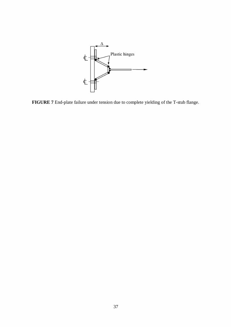
For joints with flexible end-plate connections, ductile failure modes are generally associated
with large bending deformation of the end-plate or the column flange. An equivalent T-stub
approach can be used to predict the predominant failure mode of these components[2,9]
and
thus to estimate their ductility capacity. The three possible failure modes of a T-stub flange
involve complete yielding of the flange, bolt failure with yielding of the flange, and bolt
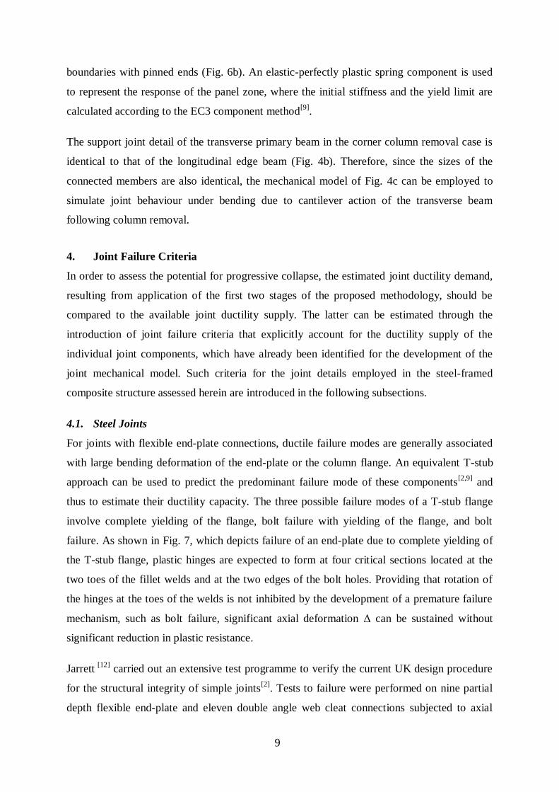
failure. As shown in Fig. 7, which depicts failure of an end-plate due to complete yielding of
the T-stub flange, plastic hinges are expected to form at four critical sections located at the
two toes of the fillet welds and at the two edges of the bolt holes. Providing that rotation of
the hinges at the toes of the welds is not inhibited by the development of a premature failure
mechanism, such as bolt failure, significant axial deformation Δ can be sustained without
significant reduction in plastic resistance.
Jarrett [12]
carried out an extensive test programme to verify the current UK design procedure
for the structural integrity of simple joints[2]
. Tests to failure were performed on nine partial
depth flexible end-plate and eleven double angle web cleat connections subjected to axial
10
load. The average maximum axial displacement Δ measured during the tests was 25.4mm and
37.2mm for the flexible end-plates and the double angle web cleats, respectively. Ductile
failure mechanisms, such as bearing failure of the end-plate or the beam web, generally
yielded higher deformation capacities. This observation was more evident in the case of the
flexible end-plates, where the behaviour of seven out of the nine specimens was significantly
compromised due to fracture of the end-plate at the weld toe resulting in less effective hinges
and smaller ultimate displacements of around 20mm. In contrast, the deformation capacities
of two specimens that failed in a ductile manner were considerably higher averaging 40.0mm.
A similar experimental study performed by Owens and Moore[13]
on eight simple joint details
concluded that the available ductility supply depends on the size of the connection, the
thickness of the plate and the number of bolt-rows. The average maximum axial displacement
Δ of the four double angle web cleat specimens that were tested was equal to 37.3mm. The
deformation capacity of the four end-plate specimens was relatively lower with an average
maximum axial displacement of 26.8mm. Based on these experimental results, a deformation
capacity of 30mm is assumed for the critical component of the joints with flexible end-plate
connections considered in this study. It is noted that, since the employed connections satisfy
the code prescribed detailing requirements that can guarantee the effectiveness of the formed
plastic hinges[2,9]
, they are expected to fail in a ductile manner (i.e. due to complete yielding
of the end-plate). Accordingly, the adopted deformation limit is considered to err on the safe
side.
Joints with fin plate connections, which are popular in countries with low seismic hazard,
such as the UK, mainly derive their rotation capacity from hole distortions in the fin plate
and/or the beam web, out-of-plane bending of the plate, and shear deformation of the bolts.
The contribution of these components cannot be easily quantified. An experimental study
carried out on eighteen fin plate connections between I-section beams and RHS columns
reported maximum axial deformations at failure in excess of 30mm in most of the cases[14]
.
However, yield of the column section around the connection and large column deflections
were observed in all tests, thus greatly increasing the overall measured deformation capacity.
For other joint configurations, such as major axis beam-to-column joints with an I-section
column and beam-to-beam joints, significant deflection of the supporting member is unlikely
to occur. Therefore, until further experimental validation becomes available, a deformation
limit of 20mm, applied to the bolt-row furthest from the centre of compression, is taken into
account for this connection type. For the standard fin plate connections recommended by the
11
UK design guidelines[2]
, this limit is equal to one bolt diameter as well as equal to half of the
vertical edge distance (40mm) and slightly less than half of the horizontal edge distance
(50mm or 60mm) of the plate.
Even when the overall component response of a bolted connection is relatively ductile, for
example due to plate yielding in bending rather than bolt failure, it is important to check that
the resistance of brittle sub-components is not exceeded in the presence of strain-hardening.
Hence, in addition to the limits prescribed above, the deformation capacity of the critical
component should be limited to the ultimate deformation Δu resulting from the following
equation:
1
1
u y yu
F F K
K
(1)
where Fu is the ultimate capacity associated with a brittle sub-component (all sub-components
assumed to be in series to form the overall component), such as bolts in shear or tension, Fy is
the component yield resistance, Δy is the component yield limit given by Fy/K0, where K0 is
the component initial stiffness, and K1 is the post-yield stiffness.. It should be noted that the
derivation of Eq. (1) is based on a simplified bilinear idealisation of the behaviour of the
overall component response.
Finally, a comprehensive estimation of the deformation capacity of a steel joint requires
checking strength-based failure modes associated with exceedance of the connection shear
resistance or the resistance of the column web and the beam flange/web in compression. The
occurrence of such modes can lead to premature shear failure or local buckling that can
significantly compromise the deformation capacity of the joint. Therefore, a practical
approach is to limit the ductility supply to the range of joint response excluding these modes.
4.2. Composite Joints
When composite joint details are used, apart from ductility limits in the steel components,
additional ductility limits may also be imposed by the slab. Considering the interaction
between the steel connection components and the slab, possible failure modes are those
associated with tensile reinforcement rupture in hogging moment regions, concrete crushing
in sagging moment regions, buckling of compressed regions in the steel members, as well as
slip of the shear connectors.

12
Regarding reinforcement failure, the model proposed by Anderson et al.[15]
can be used to
determine the elongation Δu,s at rupture as a function of the slab reinforcement ratio ρ. The
model employs the simplified stress-strain relationship for embedded reinforcement
introduced in the CEB-FIP Model Code[16]
to obtain the ultimate average strain εsmu at crack
locations, while it also defines a „transmission‟ length Lt over which εsmu is assumed to act.
The deformation capacities calculated based on the proposed model are generally consistent,
except for very low reinforcement ratios, typically less than 0.50%, where multiple cracking
does not occur, and thus the transmission length should be limited by the reinforcement rather
than the concrete tensile strength. In this case, assuming a rigid-hardening response for the
steel, Lt can be calculated as follows:
4
syt
sm
L
(2)
where γ is the overstrength factor expressed as the percentage difference between the ultimate
stress σsu and the yield stress σsy of bare steel, Ø is the diameter of the rebars, and τsm is the
average bond stress. Therefore, if the steel strain varies linearly along the transmission length,
Δu,s is obtained from:
,0
2t
suu s tsu
t
Lx dx L
L
(3)
where εsu is the ultimate strain of bare steel, while the factor of 2 accounts for the contribution
from both sides of the crack.
As noted above, additional ductility supply can be provided through slip along the shear
connection. However, a straightforward estimation of this supply is not feasible because there
are several uncertainties associated with the behaviour of the connectors. Also, for structures
designed in accordance with most current design standards, only full shear connection is
permitted in the hogging moment regions. In this case, the slip of the shear connectors is
expected to be minimal compared to the elongation of the reinforcement. Yet, a methodology
for estimating the slip of the shear connection is given in[15]
.

13
5. Peripheral Column Removal
Progressive collapse assessment is performed on the second lowest level of idealisation (i.e.
single floor plate) using simplified assembly of the pseudo-static response, as discussed in
Sections 3.2.2 and 4.1 of the companion paper[1]
. Nevertheless, to gain an insight of the
relative contributions of the floor components, the gravity load is crudely apportioned to the
longitudinal beams, ignoring the contribution of the transverse beam, and each beam is also
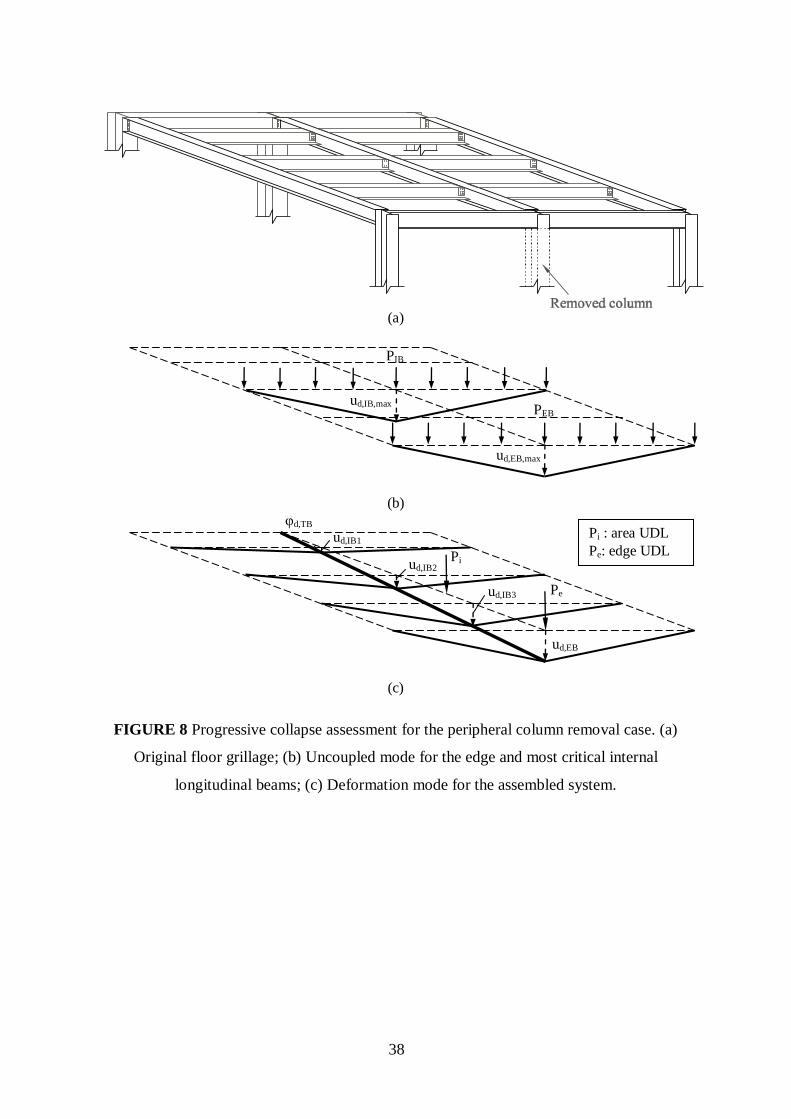
assessed independently at the lowest level of idealisation. As illustrated in Fig. 8, the
assessment at the assembled floor plate level is more realistic than on the lower level of
uncoupled beams because it also accounts for redundancy, or the presence of alternative load
paths, due to interaction between the longitudinal beams and the transverse beam. This is
accommodated by the proposed multi-level approach which permits progressive model
refinement by simplified assembly of the lower level pseudo-static responses directly at the
next level of idealisation.
Based on several recent progressive collapse guidelines[3,17, 18,19,20]
, the recommended level of
imposed loads at the time of column removal varies from 25% to 50%. Although application
of the proposed method is clearly insensitive to this parameter, the service load combination
for appraising the robustness of the examined structure is taken as DL + 0.25 IL, where DL
and IL are the dead and imposed loads acting on the floor plate, respectively. Based on the
unfactored gravity load values given in Section 2.1 and the dimensions of the floor plate
shown in Fig. 2a, the total uniformly distributed area load (Pi) is equal to 642.3kN.
Furthermore, the uniformly distributed edge load (Pe) carried by the edge longitudinal beam
due to the additional façade load is 99.7kN.
To obtain the nonlinear static response of the individual beams affected by the column
removal, which is required by the simplified dynamic approach for establishing the pseudo-
static curves[1]
, the nonlinear structural analysis program ADAPTIC[11]
is used. The edge and
internal secondary beams are assumed to sustain a uniformly distributed load (UDL) pattern
(Fig. 8b). The UDL intensity is calculated from the tributary area of the corresponding
longitudinal strips (Fig. 2a) and applied to the beam models as proportionally varied load.
Using the gravity load combination DL + 0.25 IL, the apportioned total UDL (PEB) on the
edge longitudinal beam is equal to 176.8kN, while the respective value for the most critical
internal longitudinal beam associated with the 3m-wide strip is PIB = 195.1kN. Furthermore,
following column removal the transverse primary beam acts largely as a cantilever, with most
of the deformation concentrated at the support joint, thus for simplicity its static response
14
characteristics are obtained under an end moment. Nevertheless, it is emphasised that,
although the assumed load distribution on the system components is realistic, the most
important factor in establishing the nonlinear static response of the individual beams is the
dominant deformation mode and not the actual load pattern[1]
. It is also worth noting that the
moment in the transverse to edge beam connection (Fig. 8a) is ignored, since it is deemed to
be significantly smaller compared to that developed at the internal support joint of the
transverse primary beam.
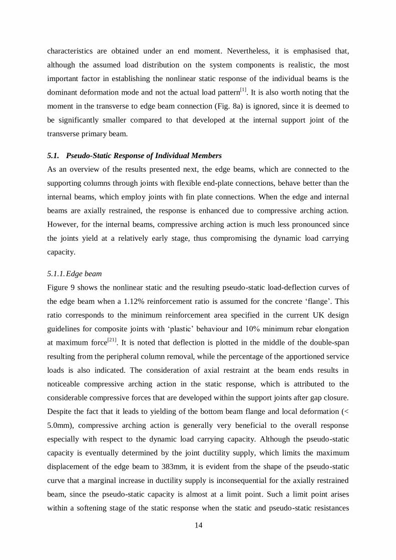
5.1. Pseudo-Static Response of Individual Members
As an overview of the results presented next, the edge beams, which are connected to the
supporting columns through joints with flexible end-plate connections, behave better than the
internal beams, which employ joints with fin plate connections. When the edge and internal
beams are axially restrained, the response is enhanced due to compressive arching action.
However, for the internal beams, compressive arching action is much less pronounced since
the joints yield at a relatively early stage, thus compromising the dynamic load carrying
capacity.
5.1.1. Edge beam
Figure 9 shows the nonlinear static and the resulting pseudo-static load-deflection curves of
the edge beam when a 1.12% reinforcement ratio is assumed for the concrete „flange‟. This
ratio corresponds to the minimum reinforcement area specified in the current UK design
guidelines for composite joints with „plastic‟ behaviour and 10% minimum rebar elongation
at maximum force[21]
. It is noted that deflection is plotted in the middle of the double-span
resulting from the peripheral column removal, while the percentage of the apportioned service
loads is also indicated. The consideration of axial restraint at the beam ends results in
noticeable compressive arching action in the static response, which is attributed to the
considerable compressive forces that are developed within the support joints after gap closure.
Despite the fact that it leads to yielding of the bottom beam flange and local deformation (<
5.0mm), compressive arching action is generally very beneficial to the overall response
especially with respect to the dynamic load carrying capacity. Although the pseudo-static
capacity is eventually determined by the joint ductility supply, which limits the maximum
displacement of the edge beam to 383mm, it is evident from the shape of the pseudo-static
curve that a marginal increase in ductility supply is inconsequential for the axially restrained
beam, since the pseudo-static capacity is almost at a limit point. Such a limit point arises
within a softening stage of the static response when the static and pseudo-static resistances
15
become equal, in which case the subsequent pseudo-static response is also characterised by
softening, and any further enhancement of ductility supply beyond the limit point becomes
therefore immaterial[1]
. Regarding the predominant failure mechanism, the ultimate tensile
capacity of the end-plate at the bolt-row of the midspan joint which is furthest from the centre
of compression is reached immediately before reinforcement rupture at the support joint. On
the other hand, as also illustrated in Fig. 9, the response of the axially unrestrained beam is
significantly compromised by the absence of compressive arching action. The pseudo-static
capacity is governed in this case by the available ductility supply of the support joints, with
failure occurring due to reinforcement rupture associated with rebar elongation of 14.9mm.
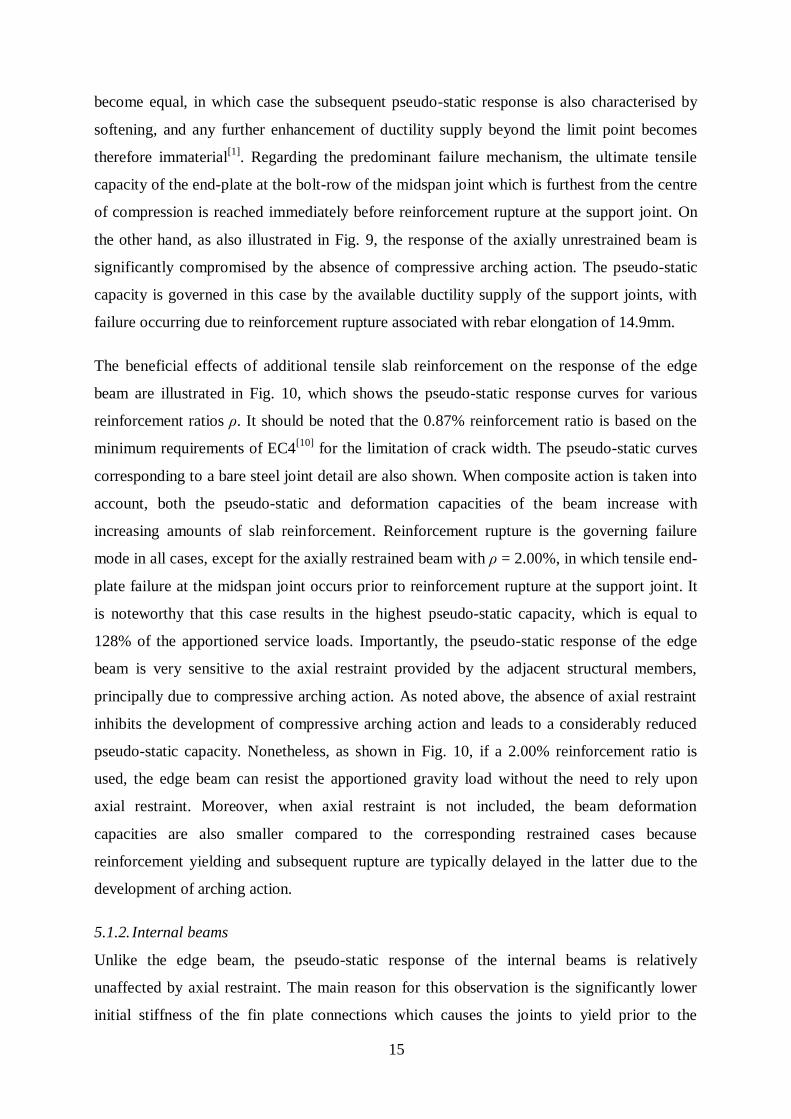
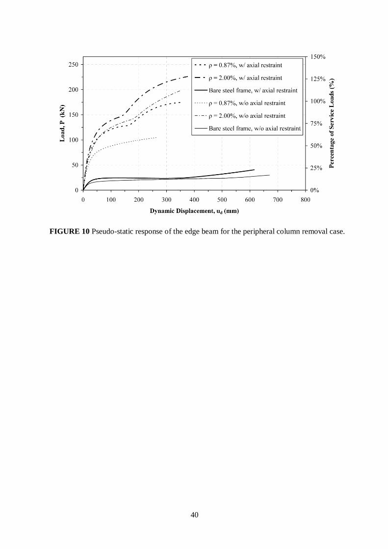
The beneficial effects of additional tensile slab reinforcement on the response of the edge
beam are illustrated in Fig. 10, which shows the pseudo-static response curves for various
reinforcement ratios ρ. It should be noted that the 0.87% reinforcement ratio is based on the
minimum requirements of EC4[10]
for the limitation of crack width. The pseudo-static curves
corresponding to a bare steel joint detail are also shown. When composite action is taken into
account, both the pseudo-static and deformation capacities of the beam increase with
increasing amounts of slab reinforcement. Reinforcement rupture is the governing failure
mode in all cases, except for the axially restrained beam with ρ = 2.00%, in which tensile end-
plate failure at the midspan joint occurs prior to reinforcement rupture at the support joint. It
is noteworthy that this case results in the highest pseudo-static capacity, which is equal to
128% of the apportioned service loads. Importantly, the pseudo-static response of the edge
beam is very sensitive to the axial restraint provided by the adjacent structural members,
principally due to compressive arching action. As noted above, the absence of axial restraint
inhibits the development of compressive arching action and leads to a considerably reduced
pseudo-static capacity. Nonetheless, as shown in Fig. 10, if a 2.00% reinforcement ratio is
used, the edge beam can resist the apportioned gravity load without the need to rely upon
axial restraint. Moreover, when axial restraint is not included, the beam deformation
capacities are also smaller compared to the corresponding restrained cases because
reinforcement yielding and subsequent rupture are typically delayed in the latter due to the
development of arching action.
5.1.2. Internal beams
Unlike the edge beam, the pseudo-static response of the internal beams is relatively
unaffected by axial restraint. The main reason for this observation is the significantly lower
initial stiffness of the fin plate connections which causes the joints to yield prior to the
16
development of compressive arching action. Consequently, the pseudo-static capacity of the
internal beams is distinctly compromised even if a high amount of reinforcement is provided.
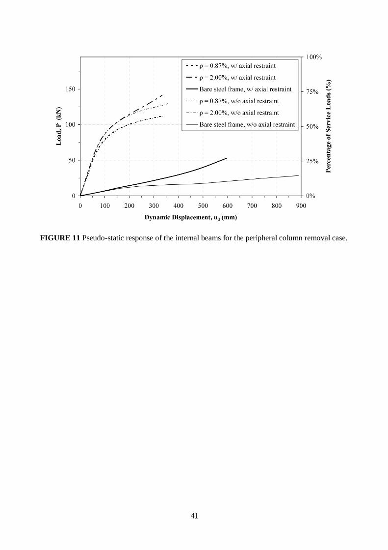
As illustrated in Fig. 11, which shows the variation of the pseudo-static response with the
amount of slab reinforcement for the most critical internal secondary beam, the pseudo-static
capacity of the axially restrained beam increases from 58% of the apportioned service load for
ρ = 0.87% to 72% for ρ = 2.00%. When axial restraint is not taken into account, the
corresponding values are 57% and 67%, respectively. It is also worth noting that, irrespective
of the amount of slab reinforcement or the consideration of axial restraint, failure is governed
by the deformation limit of 20mm imposed on the bolt-row furthest from the centre of
compression at the midspan joint, and thus the limiting deflection in all cases is around
350mm. However, even if an enhanced failure criterion is used for estimating the ductility
supply of the fin plate (e.g. 30mm), as suggested by some experimental evidence[14]
, the
resulting increase in the pseudo-static capacity of the beam is still insufficient to resist the full
apportioned service loads.
5.1.3. Transverse beam
In view of the above results, it is evident that the uncoupled system of the edge and internal
beams (Fig. 8b) does not provide sufficient pseudo-static resistance to the suddenly applied
gravity load, particularly with the internal secondary beam supplying at the highest
reinforcement ratio and under full axial restraint, a maximum pseudo-static capacity of only
72% of the approximately apportioned gravity load. It is possible, however, for the coupled
system (Fig. 8c) to furnish the required pseudo-static resistance if the contribution from the
transverse beam is significant, and the ductility supply of all beams is near-optimal, rendering
the influence of redundancy positive[1]
.
In order to assemble the pseudo-static response of the couple floor plate system, the pseudo-
static response of the cantilever transverse primary beam is obtained for a mode in which the
rotational deformations are concentrated at the support joint. Accordingly, the beam is
considered under an end moment, even though it could also be considered under vertical
loading without influencing the assembled system response, where the resulting pseudo-static
moment-rotation curves are depicted in Fig. 12. Since the beam is connected to the supporting
column through a major axis flexible end-plate joint (Fig. 6a), the rotation includes the
influence of the panel zone shear deformation. In general, similar to the longitudinal edge
beam, which uses the same connection type, both the resistance and the rotation capacity of
the transverse beam increase with increasing reinforcement. The joint ductility supply of the
17
two lightly reinforced beams, whose support joints satisfy the minimum requirements set by
the current UK design guidelines[21]
and EC4[10]
, is governed by reinforcement rupture, which
occurs at an elongation of 8.8mm for ρ = 0.45% and 13.9mm for ρ = 0.87%. It is noted that,
unlike EC4[10]
, in which a constant ratio is recommended, the minimum reinforcement area
prescribed by the UK guidelines[21]
depends on the depth of the supported steel beam. Hence,
the smaller depth of the transverse primary beam in combination with its significantly larger
effective width due to cantilever action result in a considerably smaller minimum ρ (0.45%)
compared to the edge beam (1.12%). When considering a relatively high 2.00% reinforcement
ratio, yielding of the column web panel in shear occurs before reinforcement rupture as a
result of the significant tensile force developed at the reinforcement level. In this case, due to
the lack of experimental data on the shear deformation capacity of column web panels, it is
assumed that failure occurs when the elongation of the steel along the tensile diagonal of the
panel zone reaches 5%. Due to the different failure mechanism, the beam with ρ = 2.00% has
considerably higher resistance and ductility supply than the beams with ρ = 0.45% and ρ =
0.87%.
5.2. Pseudo-Static Capacity of Assembled Floor Plate
A grillage approximation is used to model the floor plate (Fig. 8c), and since this is the target
level of structural idealisation for failure assessment, only the pseudo-static capacity, rather
the full pseudo-static load-deflection response, is required. Accordingly, the pseudo-static
capacity for the single degree-of-freedom (SDOF) floor plate system can be obtained from the
simplified assembly of the individual beam pseudo-static resistances, as discussed in the
companion paper[1]
, at the critical level of deformation corresponding to first failure in a joint
of one of the beams. Since for the present study the pseudo-static responses of all beams vary
monotonically up to their respective ductility supply, as can be verified from Figs. 10-12, the
pseudo-static resistance at first failure will be the maximum pseudo-static capacity for the
assembled floor plate. Table 4 provides the overall critical deformation profile (Fig. 8c),
based on the compatibility factors of Table 3, for the following five cases:
Case 1 – both composite action and axial restraint are considered. The minimum
reinforcement area prescribed by the UK design guidelines[21]
is employed in both
directions of the slab.
18
Case 2 – same as Case 1 except that a 0.87% reinforcement ratio is used,
corresponding to the minimum amount of reinforcement specified by EC4[10]
for crack
width limitation.
Case 3 – same as Case 1 with a uniform 2.00% reinforcement ratio in the slab.
Case 4 – same as Case 3 without consideration of axial restraint in the longitudinal
direction.
Case 5 – bare steel frame design is assumed for all beams, and axial restraint is
considered.
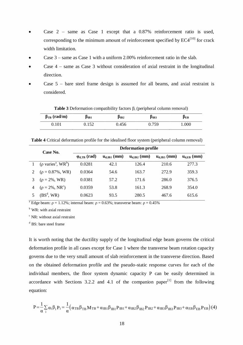
Table 3 Deformation compatibility factors βi (peripheral column removal)
βTB (rad/m) βIB1 βIB2 βIB3 βEB
0.101 0.152 0.456 0.759 1.000
Table 4 Critical deformation profile for the idealised floor system (peripheral column removal)
Case No. Deformation profile
φd,TB (rad) ud,IB1 (mm) ud,IB2 (mm) ud,IB3 (mm) ud,EB (mm)
1 (ρ variesa, WR
b) 0.0281 42.1 126.4 210.6 277.3
2 (ρ = 0.87%, WR) 0.0364 54.6 163.7 272.9 359.3
3 (ρ = 2%, WR) 0.0381 57.2 171.6 286.0 376.5
4 (ρ = 2%, NRc)
0.0359 53.8 161.3 268.9 354.0
5 (BSd, WR)
0.0623 93.5 280.5 467.6 615.6
a Edge beam: ρ = 1.12%; internal beam: ρ = 0.63%; transverse beam: ρ = 0.45%
b WR: with axial restraint
c NR: without axial restraint
d BS: bare steel frame
It is worth noting that the ductility supply of the longitudinal edge beam governs the critical
deformation profile in all cases except for Case 1 where the transverse beam rotation capacity
governs due to the very small amount of slab reinforcement in the transverse direction. Based
on the obtained deformation profile and the pseudo-static response curves for each of the
individual members, the floor system dynamic capacity P can be easily determined in
accordance with Sections 3.2.2 and 4.1 of the companion paper[1]
from the following
equation:
i TB IB1 IB2 IB3 EBi TB IB1 IB2 IB3 EBi TB IB1 IB2 IB3 EBi
1 1P β β β β β βα α α α α αP M P P P P
α α (4)
19
In the above, the value of the weighting factors (αEB, αIB1, αIB2, and αIB3) for the longitudinal
edge and internal beams should be taken as 0.5, since they are assumed to sustain a UDL. On
the other hand, αTB for the transverse beam is 1.0, since the applied moment performs work
directly over the measured rotation (φd,TB). Finally, the weighting factor (α) for the floor plate
under the considered deformation mode accounts for the uniformly distributed area load (P i)
and the uniformly distributed edge load (Pe) according to work equivalence:
i e i e i ei eα 0.25 0.5α αP P P P P P (5)
leading to:
i e
i e
0.25 0.5P Pα 0.284
P P
(6)
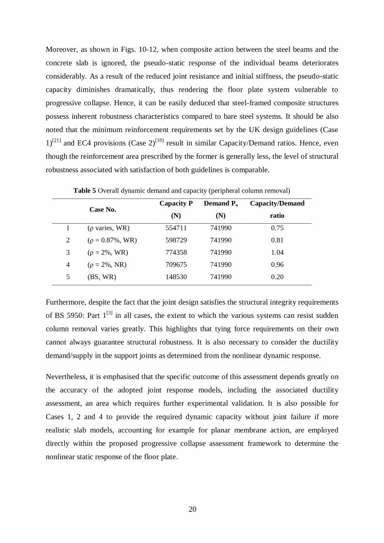
The overall dynamic capacity P at the critical deformation level as well as the corresponding
demand Po = Pi + Pe for the five cases investigated are summarized in Table 5. It can be seen
that the floor plate, approximated using a grillage model, lacks the necessary pseudo-static
capacity to prevent the initiation of progressive collapse in all cases except for Case 3. This is
mainly attributed to the fact that the positive effects of redundancy due to the contribution of
the transverse beam are not fully exploited, since the pseudo-static resistance of the internal
secondary beams is well below their capacity, with the critical deformation governed by the
ductility supply of the edge secondary beam. Accordingly, enhancing the ductility of the
internal beams is inconsequential, with their ductility supply already exceeding the optimal
ductility, and hence experimental evidence suggesting that fin plates are even more ductile
than assumed[14]
is immaterial for the idealised floor plate system under consideration. This
observation is even more pronounced for Case 1, where the early failure of the transverse
beam support joint significantly compromises the overall dynamic capacity of the floor
grillage, since the pseudo-static resistance of the longitudinal beams does not reach its optimal
ductility demand.
Nonetheless, based on the calculated Capacity/Demand ratios (or unity factors) given in Table
5, it is clear that the estimated pseudo-static capacity is not much lower than the demand
posed by the applied gravity loading, with the exception of the system ignoring composite
action (Case 5). Although this bare steel system exhibits a relatively ductile behaviour, it is
insufficient for the mobilisation of full tensile catenary action in the edge beam (Fig. 10).
20
Moreover, as shown in Figs. 10-12, when composite action between the steel beams and the
concrete slab is ignored, the pseudo-static response of the individual beams deteriorates
considerably. As a result of the reduced joint resistance and initial stiffness, the pseudo-static
capacity diminishes dramatically, thus rendering the floor plate system vulnerable to
progressive collapse. Hence, it can be easily deduced that steel-framed composite structures
possess inherent robustness characteristics compared to bare steel systems. It should be also
noted that the minimum reinforcement requirements set by the UK design guidelines (Case
1)[21]
and EC4 provisions (Case 2)[10]
result in similar Capacity/Demand ratios. Hence, even
though the reinforcement area prescribed by the former is generally less, the level of structural
robustness associated with satisfaction of both guidelines is comparable.
Table 5 Overall dynamic demand and capacity (peripheral column removal)
Case No. Capacity P
(N)
Demand Po
(N)
Capacity/Demand
ratio
1 (ρ varies, WR) 554711 741990 0.75
2 (ρ = 0.87%, WR) 598729 741990 0.81
3 (ρ = 2%, WR) 774358 741990 1.04
4 (ρ = 2%, NR)
709675 741990 0.96
5 (BS, WR)
148530 741990 0.20
Furthermore, despite the fact that the joint design satisfies the structural integrity requirements
of BS 5950: Part 1[3]
in all cases, the extent to which the various systems can resist sudden
column removal varies greatly. This highlights that tying force requirements on their own
cannot always guarantee structural robustness. It is also necessary to consider the ductility
demand/supply in the support joints as determined from the nonlinear dynamic response.
Nevertheless, it is emphasised that the specific outcome of this assessment depends greatly on
the accuracy of the adopted joint response models, including the associated ductility
assessment, an area which requires further experimental validation. It is also possible for
Cases 1, 2 and 4 to provide the required dynamic capacity without joint failure if more
realistic slab models, accounting for example for planar membrane action, are employed
directly within the proposed progressive collapse assessment framework to determine the
nonlinear static response of the floor plate.
21
6. Corner Column Removal
Similar to the previous case, progressive collapse assessment is performed at the single floor
plate level, where the system pseudo-static response is assembled from that of individual
beams using a grillage approximation[1]
. Based on the floor plate geometry (Fig. 2b), the
service gravity loads, taken as DL + 0.25 IL, result in a total uniformly distributed area load
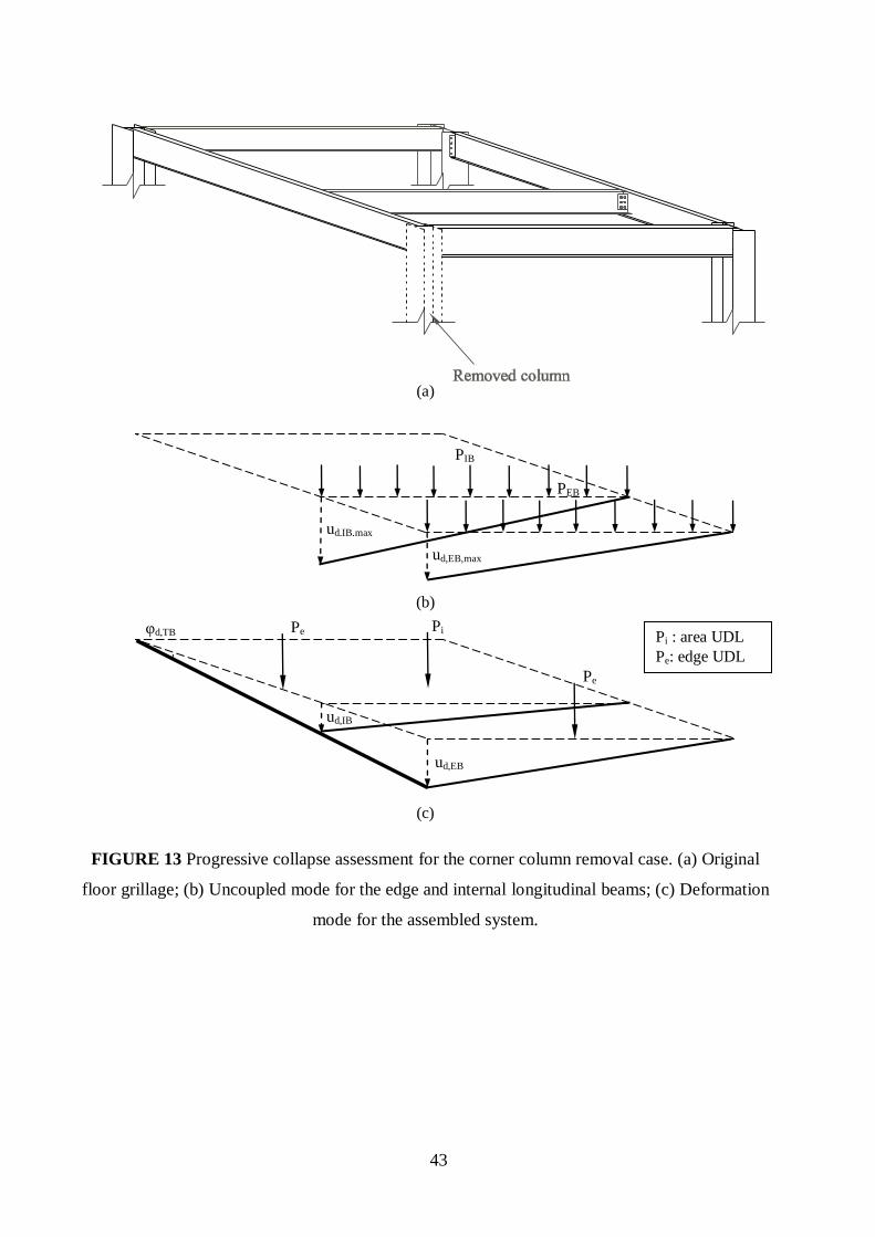
(Pi) of 105.7kN. Moreover, as shown in Fig. 13c, the uniformly distributed edge loads (Pe)
acting on the longitudinal and transverse edge beams are 33.2kN and 40.5kN, respectively.
The uncoupled individual beam assessment is based again on apportioning the gravity loads
to the longitudinal beams only, ignoring the influence of the transverse beam. Similar to the
peripheral column removal case, a UDL and an applied moment are the assumed load patterns
for the longitudinal secondary beams (Fig. 13b) and for the transverse primary beam,
respectively. Based on the tributary area of the corresponding strips (Fig. 2b), the apportioned
total UDL carried by the longitudinal edge and internal beams are PEB = 53.6kN and PIB =
52.8kN, respectively. These loads are applied to the corresponding cantilever beam models
resulting from column removal as proportionally varied loads to establish the nonlinear static
response. Again, the developed moment in the transverse to edge beam connection (Fig. 13a)
is assumed to be negligible and thus ignored. It is also noted that, with regard to individual
members, the principal difference between the peripheral and the corner column removal
scenarios is the absence of axial restraint provided by the surrounding undamaged structure in
the latter case due to cantilever beam action in both directions.
6.1. Pseudo-Static Response of Individual Members
As a result of the shorter longitudinal span (4m) compared to the previous case (6m), both the
edge and internal beams affected by the corner column removal are generally able to resist the
apportioned instantaneous gravity loads, providing that composite action is taken into
account[22]
. It is worth noting that the beams can achieve this enhanced behaviour without the
need to rely upon catenary effects. Nonetheless, the superiority of flexible end-plates over fin
plates is also demonstrated in this case, since the pseudo-static capacity of the internal beam,
which employs the latter connection type (Fig. 5b), is smaller compared to the edge beam,
which is connected to the supporting column through a flexible end-plate (Fig. 4b). Moreover,
similar to the previous case, the composite beams are much more robust compared to the bare
steel beams, which are clearly incapable of withstanding the suddenly applied apportioned
gravity loads. Finally, the provision of additional slab reinforcement increases both the
22
pseudo-static and deformation capacities of the composite beams, while reinforcement rupture
is typically the predominant failure mechanism[22]
.
6.2. Pseudo-Static Capacity of Assembled Floor Plate
To obtain an estimate of the overall dynamic capacity of the floor plate accounting for
coupling effects, the pseudo-static responses of the individual beams are assembled based on
a grillage approximation. Similar to the peripheral column removal case, the simplified
assembly procedure described in the companion paper[1]
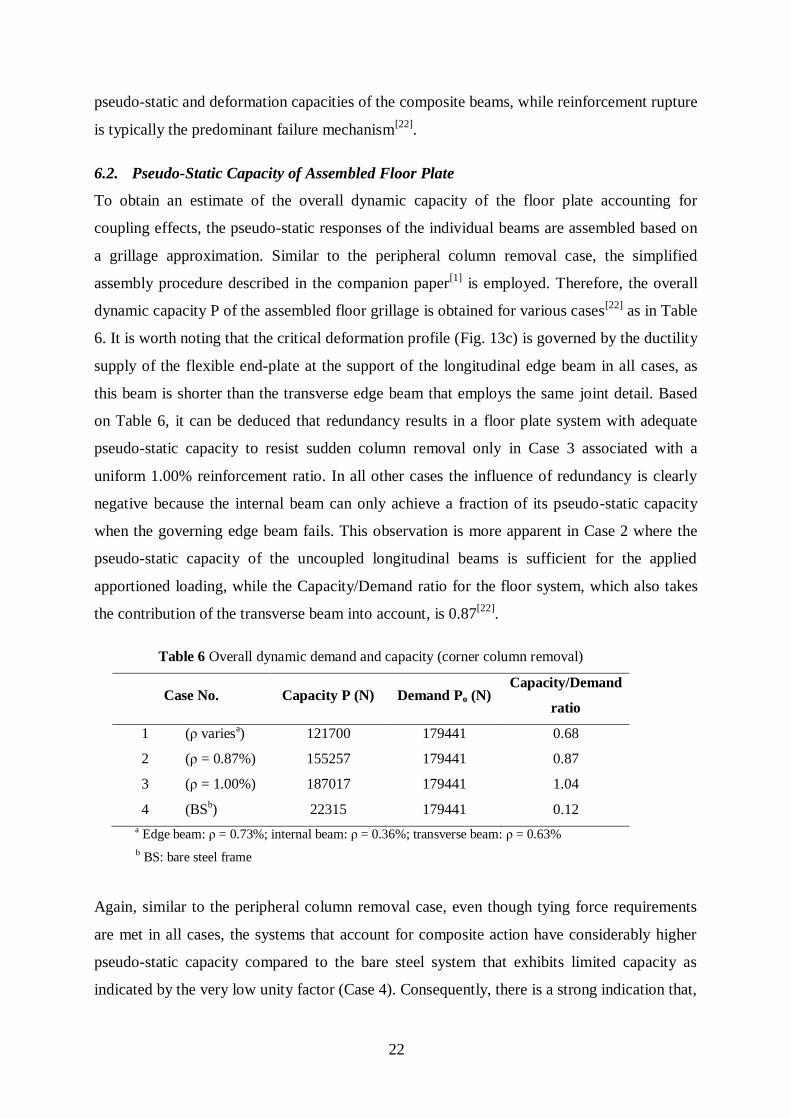
is employed. Therefore, the overall
dynamic capacity P of the assembled floor grillage is obtained for various cases[22]
as in Table
6. It is worth noting that the critical deformation profile (Fig. 13c) is governed by the ductility
supply of the flexible end-plate at the support of the longitudinal edge beam in all cases, as
this beam is shorter than the transverse edge beam that employs the same joint detail. Based
on Table 6, it can be deduced that redundancy results in a floor plate system with adequate
pseudo-static capacity to resist sudden column removal only in Case 3 associated with a
uniform 1.00% reinforcement ratio. In all other cases the influence of redundancy is clearly
negative because the internal beam can only achieve a fraction of its pseudo-static capacity
when the governing edge beam fails. This observation is more apparent in Case 2 where the
pseudo-static capacity of the uncoupled longitudinal beams is sufficient for the applied
apportioned loading, while the Capacity/Demand ratio for the floor system, which also takes
the contribution of the transverse beam into account, is 0.87[22]
.
Table 6 Overall dynamic demand and capacity (corner column removal)
Case No. Capacity P (N) Demand Po (N) Capacity/Demand
ratio
1 (ρ variesa)
121700 179441 0.68
2 (ρ = 0.87%) 155257 179441 0.87
3 (ρ = 1.00%) 187017 179441 1.04
4 (BSb)
22315 179441 0.12
a Edge beam: ρ = 0.73%; internal beam: ρ = 0.36%; transverse beam: ρ = 0.63%
b BS: bare steel frame
Again, similar to the peripheral column removal case, even though tying force requirements
are met in all cases, the systems that account for composite action have considerably higher
pseudo-static capacity compared to the bare steel system that exhibits limited capacity as
indicated by the very low unity factor (Case 4). Consequently, there is a strong indication that,
23
in case of an extreme event that can lead to instantaneous loss of a vertical support member,
the satisfaction of the tying force requirements prescribed by BS 5950[3]
cannot always
guarantee adequate protection against progressive collapse.
7. Conclusions
This paper presents the application of a new simplified design-oriented method for
progressive collapse assessment of multi-storey buildings subject to sudden loss of a vertical
support member. Two likely scenarios, removal of either a peripheral or a corner column in a
typical steel-framed composite building, are investigated. To demonstrate the practicality of
the proposed approach, assessment is based on the second lowest level of structural
idealisation associated with the response of a single floor plate. The simplified assembly
procedure introduced in the companion paper is used to assemble the pseudo-static responses
of the individual components of the floor plate affected by the column removal in each case.
Nonetheless, the beams are also assessed independently to evaluate the importance of their
relative contribution to the overall pseudo-static capacity of the floor plate system.
The case study has demonstrated that steel-framed composite buildings with typical structural
configurations can be prone to progressive collapse initiated by local failure of a vertical
support member. Susceptibility to progressive collapse is mainly related to the span sizes of
the beams required to safely transfer the instantaneously applied gravity loads to the
remaining undamaged structure as well as the joint detail used at the beam ends. With regard
to the latter observation, this study has concluded that, due to their increased flexibility and
reduced strength, fin plates, used for the beam-to-beam joints of the internal secondary beams,
are much less adequate than flexible end-plates, primarily employed for the beam-to-column
joints. Although the behaviour of the beams utilizing fin plates is generally more ductile, their
pseudo-static capacity is significantly compromised. Therefore, the use of fin plates, which
are currently very popular in countries with low seismicity, should be carefully reviewed as
far as robustness design is concerned, especially in the case of relatively long spans.
The supply of additional slab reinforcement in the hogging moment regions can generally
have a beneficial effect on both the pseudo-static and deformation capacities of the beams.
However, there seem to be upper limits on the amount of additional reinforcement that should
be provided because an excessive reinforcement area can mobilise undesirable non-ductile
failure mechanisms primarily associated with local buckling in compressed regions in the
steel beams. The response can be further improved if axial restraint provided by the adjacent
24
structure can be relied upon. This demonstrates the need for realistic joint response models
that can capture the interaction between bending moment and axial force and estimate the
joint ductility supply with sufficient accuracy.
This paper has also shown that the extent to which different systems corresponding to various
modelling assumptions can withstand sudden column removal varies considerably despite
satisfaction of the code prescribed tying force requirements in all cases. In this context, the
bare steel systems considered in this study have exhibited limited pseudo-static capacity
rendering them very vulnerable to progressive collapse due to instantaneous column loss.
Therefore, tying force requirements alone cannot invariably ensure structural integrity without
explicit consideration of the ductility demand/supply in the support joints of the affected
members. Similar observations resulting from application of the proposed method to a large
number of structures as well as a variety of structural systems could underpin the need for a
thorough revision of the structural integrity requirements currently used for robustness design
in the UK.
As a general remark on its applicability, it should be noted that the new method offers for the
first time a rational design-oriented framework that deals with dynamic effects and ductility
considerations in progressive collapse assessment. Moreover, it can be readily implemented in
a design environment and, thus, it is the authors‟ belief that it has great potential to constitute
an effective tool for design decisions. Further development of the proposed method should
include extensive experimental validation and calibration, particularly in relation to the joint
response and ductility limits under combined bending and axial actions.
Acknowledgements
The authors would like to acknowledge the financial support provided for this work by ARUP
and EPSRC under a Case award scheme. The significant input into this project of several
ARUP staff, especially Faith Wainwright, Mike Banfi and Michael Willford, is also gratefully
acknowledged.

25
8. References
1. Izzuddin, B.A., Vlassis, A.G., Elghazouli, A.Y., and Nethercot, D.A. (2006). “Progressive
Collapse of Multi-Storey Buildings due to Sudden Column Loss – Part I: Simplified
Assessment Framework,” (Companion Paper).
2. British Construction Steelwork Association/Steel Construction Institute (2002). “Joints in
Steel Construction: Simple Connections,” London, UK.
3. British Standards Institution (2001). “BS 5950-1:2000: Structural use of steelwork in
building, Part 1: Code of practice for design – Rolled and welded sections,” London, UK.
4. Song, L., Izzuddin, B. A., Elnashai, A. S., and Dowling, P. J. (2000). “An integrated
adaptive environment for fire and explosion analysis of steel frames – Part I: analytical
models,” Journal of Constructional Steel Research 53, pp. 63-85.
5. Izzuddin B. A., Tao X. Y., and Elghazouli, A. Y. (2004). “Realistic Modelling of
Composite and Reinforced Concrete Floor Slabs under Extreme Loading I: Analytical
Method,” Journal of Structural Engineering, ASCE 130(12), pp.1972-1984.
6. Izzuddin, B. A. (2005). “A Simplified Model for Axially Restrained Beams Subject to
Extreme Loading,” International Journal of Steel Structures 5, pp. 421-429.
7. Vlassis, A., Izzuddin, B., Elghazouli, A., and Nethercot, D. (2005). “Simplified
Progressive Collapse Analysis of Floor Systems,” Proceedings of IABSE Symposium on
Structures and Extreme Events, Lisbon, Portugal, pp. 252-253 & CD.
8. Faella, C., Piluso, V., and Rizzano, G. (2000). Structural Steel Semirigid Connections:
Theory, Design and Software, CRC Press LLC, Boca Raton, FL.
9. European Committee for Standardization (2005). “EN 1993-1-8:2003, Eurocode 3: Design
of Steel Structures - Part 1-8: Design of Joints,” Brussels, Belgium.
10. European Committee for Standardization (2004). “EN 1994-1-1:2004, Eurocode 4: Design
of Composite Steel and Concrete Structures – Part 1-1: General Rules and Rules for
Buildings,” Brussels, Belgium.
11. Izzuddin, B. A. (1991). Nonlinear Dynamic Analysis of Framed Structures, PhD Thesis,
Department of Civil Engineering, Imperial College, University of London.
26
12. Jarrett, N. D. (1990). “Axial Tests on Beam/Column Connections,” BRE Client Report CR
55/90, Building Research Establishment, Garston, Watford, UK.
13. Owens, G.W., and Moore, D.B. (1992). “The Robustness of Simple Connections,” The
Structural Engineer, 70(3), pp. 37-46.
14. Jarrett, N. D., Grantham, R. I. (1993). “Robustness Tests on Fin Plate Connections,” BRE
Client Report GD 1101, Building Research Establishment, Garston, Watford, UK.
15. Anderson, D., Aribert, J. M., Bode, H., and Kronenburger, H. J. (2000). “Design rotation
capacity of composite joints,” The Structural Engineer 78(6), pp. 25-29.
16. European Committee for Concrete (1990). “CEB-FIP Model Code 1990,” Lausanne,
Switzerland.
17. General Services Administration (2003). “Progressive Collapse Analysis and Design
Guidelines for New Federal Office Buildings and Major Modernization Projects,” USA,
June.
18. Office of the Deputy Prime Minister (ODPM) (2004). “The Building Regulations 2000,
Part A, Schedule 1: A3, Disproportionate Collapse,” London, UK.
19. American Society of Civil Engineers (ASCE) (2005). “Minimum Design Loads for
Buildings and Other Structures,” SEI/ASCE 7-05, Reston, VA, USA.
20. Department of Defense (DoD) (2005). “Unified Facilities Criteria, Design of Buildings to
Resist Progressive Collapse,” UFC 4-023-03, USA, January.
21. British Construction Steelwork Association/Steel Construction Institute (1998). “Joints in
Steel Construction: Composite Connections,” London, UK.
22. Vlassis, A. G. (2007). Progressive Collapse Assessment of Tall Buildings, PhD Thesis,
Department of Civil and Environmental Engineering, Imperial College London.

27
LIST OF FIGURES
Figure 1 Layout of the seven-storey steel-framed composite building.
Figure 2 Plan view of the floor areas affected by the column removal. (a) Peripheral
column; (b) Corner column (dimensions in mm).
Figure 3 Elevation of typical detailed finite element beam model.
Figure 4 Edge beam partial depth flexible end-plate joint. (a) Geometry for the
peripheral column removal case; (b) Geometry for the corner column removal
case; (c) Mechanical model for left side of both cases (dimensions in mm).
Figure 5 Internal beam fin plate joint. (a) Geometry for the peripheral column removal
case; (b) Geometry for the corner column removal case; (c) Mechanical model
for left side of both cases (dimensions in mm).
Figure 6 Transverse beam partial depth flexible end-plate joint for the peripheral
column removal case. (a) Geometry; (b) Mechanical model for right side and
panel zone (dimensions in mm).
Figure 7 End-plate failure under tension due to complete yielding of the flange.
Figure 8 Progressive collapse assessment for the peripheral column removal case. (a)
Original floor grillage; (b) Uncoupled mode for the edge and most critical
internal longitudinal beams; (c) Deformation mode for the assembled system.
Figure 9 Static and pseudo-static force-deflection curves for the edge beam with ρ =
1.12%.
Figure 10 Pseudo-static response of the edge beam for the peripheral column removal
case.
Figure 11 Pseudo-static response of the internal beams for the peripheral column removal
case.

28
Figure 12 Pseudo-static response of the transverse beam for the peripheral column
removal case.
Figure 13 Progressive collapse assessment for the corner column removal case. (a)
Original floor grillage; (b) Uncoupled mode for the edge and internal
longitudinal beams; (c) Deformation mode for the assembled system.
29
FIGURE 1 Layout of the seven-storey steel-framed composite building.
30
3000
3000
1500
6000 6000
Transverse (primary)
beam
Internal (secondary)
beams
Edge (secondary)
beams Fig. 4a
Fig. 5a
Fig. 6a
Removed column
2375
(a)
(b)
FIGURE 2 Plan view of the floor areas affected by the column removal. (a) Peripheral
column; (b) Corner column (dimensions in mm).
Edge (secondary)
beam
Internal (secondary) beam
3000
1875
4000
Removed column
Transverse (primary) beam
Fig. 4b
Fig. 5b
Fig. 4b
31
FIGURE 3 Elevation of typical detailed finite element beam model.
32
(a)
(b)
FIGURE 4 (Cont‟d)

33
(c)
FIGURE 4 Edge beam partial depth flexible end-plate joint. (a) Geometry for the
peripheral column removal case; (b) Geometry for the corner column removal case; (c)
Mechanical model for left side of (a) and (b) (dimensions in mm).
34
(a)
(b)
FIGURE 5 (Cont‟d)
35
(c)
FIGURE 5 Internal beam fin plate joint. (a) Geometry for the peripheral column removal
case; (b) Geometry for the corner column removal case; (c) Mechanical model for left side
of (a) and (b) (dimensions in mm).
36
(a)
(b)
FIGURE 6 Transverse beam partial depth flexible end-plate joint for the peripheral
column removal case. (a) Geometry; (b) Mechanical model for right side and panel zone
(dimensions in mm).
37
FIGURE 7 End-plate failure under tension due to complete yielding of the T-stub flange.
38
(a)
(b)
(c)
FIGURE 8 Progressive collapse assessment for the peripheral column removal case. (a)
Original floor grillage; (b) Uncoupled mode for the edge and most critical internal
longitudinal beams; (c) Deformation mode for the assembled system.
ud,EB,max
ud,IB,max PEB
PIB
ud,EB
ud,IB3
ud,IB2
ud,IB1
φd,TB
Pe
Pi
Pi : area UDL
Pe: edge UDL

39
FIGURE 9 Static and pseudo-static force-deflection curves for the edge beam with ρ = 1.12%.
40
FIGURE 10 Pseudo-static response of the edge beam for the peripheral column removal case.
41
FIGURE 11 Pseudo-static response of the internal beams for the peripheral column removal case.

42
FIGURE 12 Pseudo-static response of the transverse beam for the peripheral column removal case.
43
(a)
(b)
(c)
FIGURE 13 Progressive collapse assessment for the corner column removal case. (a) Original
floor grillage; (b) Uncoupled mode for the edge and internal longitudinal beams; (c) Deformation
mode for the assembled system.
PIB
PEB
ud,IB,max
ud,EB,max
φd,TB
Pi
ud,IB
ud,EB
Pe
Pi : area UDL
Pe: edge UDL
Pe
Related Documents