sensors Article A Novel Dentary Bone Conduction Device Equipped with Laser Communication in DSP Jau-Woei Perng 1,† , Tung-Li Hsieh 1,2, * ,† and Cheng-Yan Guo 3,† Citation: Perng, J.-W.; Hsieh, T.-L.; Guo, C.-Y. A Novel Dentary Bone Conduction Device Equipped with Laser Communication in DSP. Sensors 2021, 21, 4229. https://doi.org/ 10.3390/s21124229 Academic Editor: Javier R. Fonollosa Received: 30 March 2021 Accepted: 16 June 2021 Published: 20 June 2021 Publisher’s Note: MDPI stays neutral with regard to jurisdictional claims in published maps and institutional affil- iations. Copyright: © 2021 by the authors. Licensee MDPI, Basel, Switzerland. This article is an open access article distributed under the terms and conditions of the Creative Commons Attribution (CC BY) license (https:// creativecommons.org/licenses/by/ 4.0/). 1 Department of Mechanical and Electromechanical Engineering, National Sun Yat-Sen University, Kaohsiung 80424, Taiwan; [email protected] 2 General Education Center, College of Liberal Arts Education, Wenzao Ursuline University of Languages, Kaohsiung 80793, Taiwan 3 College of Medicine, National Taiwan University, Taipei 10617, Taiwan; [email protected] * Correspondence: [email protected]; Tel.: +886-7-342-6031 (ext. 7226) † These authors contributed equally to this work. Abstract: In this study, we designed a dentary bone conduction system that transmits and receives audio by laser. The main objective of this research was to propose a complete hardware design method, including a laser audio transmitter and receiver and digital signal processor (DSP) based digital signal processing system. We also present a digital filter algorithm that can run on a DSP in real time. This experiment used the CMU ARCTIC databases’ human-voice reading audio as the standard audio. We used a piezoelectric sensor to measure the vibration signal of the bone conduction transducer (BCT) and separately calculated the signal-to-noise ratio (SNR) of the digitally filtered audio output and the unfiltered audio output using DSP. The SNR of the former was twice that of the latter, and the BCT output quality significantly improved. From the results, we can conclude that the dentary bone conduction system integrated with a DSP digital filter enhances sound quality. Keywords: DSP-based; CMU ARCTIC databases; DSP digital filter 1. Introduction Sound is transmitted through bones. The auditory path begins with bone vibration and passes through the inner ear via the auditory nerve to the auditory center, without passing through the outer and middle ear. Sound is thus transmitted directly to the cochlea in the inner ear through the bone. This auditory path’s major function is to cause the cochlear wall to vibrate, allowing the inner ear sensors to receive the signal, which is then transmitted through the auditory nerve to the auditory center in the brain, which generates an auditory sensation. Figure 1 shows the structure of the human ear. People with hearing loss who have a normal auditory nerve can still utilize the bone conduction path to receive an auditory sensation. According to domestic and foreign research on bone conduction hearing aids, such a device usually includes a signal converter electrically connected to a vibrator. The signal converter receives the ambient sound signal and converts it into a corresponding electrical signal. A vibrating sheet is then driven by the electrical signal to generate a vibration. Users would simply press the vibrating sheet against the bones in their middle ear area to utilize the bone as a medium to transmit the frequency of the vibrating sheet to their cochlear structure and the auditory nerve, enabling perception of the sound received by the signal converter. However, the signal converter of a bone conduction hearing aid can receive sounds from all directions. Excessive sound sources or continual noise can prevent users from correctly receiving the target sound, resulting in low accuracy of sound transmission. Additionally, when an audio signal is transmitted through the air, its intensity attenuates with distance. Excessive distance between the user and the sound source can, thus, prevent smooth transmission of the audio signal to the signal converter, and the user will, therefore, be unable to receive sounds Sensors 2021, 21, 4229. https://doi.org/10.3390/s21124229 https://www.mdpi.com/journal/sensors

Welcome message from author
This document is posted to help you gain knowledge. Please leave a comment to let me know what you think about it! Share it to your friends and learn new things together.
Transcript
sensors
Article
A Novel Dentary Bone Conduction Device Equipped with LaserCommunication in DSP
Jau-Woei Perng 1,†, Tung-Li Hsieh 1,2,*,† and Cheng-Yan Guo 3,†
Citation: Perng, J.-W.; Hsieh, T.-L.;
Guo, C.-Y. A Novel Dentary Bone
Conduction Device Equipped with
Laser Communication in DSP. Sensors
2021, 21, 4229. https://doi.org/
10.3390/s21124229
Academic Editor: Javier R. Fonollosa
Received: 30 March 2021
Accepted: 16 June 2021
Published: 20 June 2021
Publisher’s Note: MDPI stays neutral
with regard to jurisdictional claims in
published maps and institutional affil-
iations.
Copyright: © 2021 by the authors.
Licensee MDPI, Basel, Switzerland.
This article is an open access article
distributed under the terms and
conditions of the Creative Commons
Attribution (CC BY) license (https://
creativecommons.org/licenses/by/
4.0/).
1 Department of Mechanical and Electromechanical Engineering, National Sun Yat-Sen University,Kaohsiung 80424, Taiwan; [email protected]
2 General Education Center, College of Liberal Arts Education, Wenzao Ursuline University of Languages,Kaohsiung 80793, Taiwan
3 College of Medicine, National Taiwan University, Taipei 10617, Taiwan; [email protected]* Correspondence: [email protected]; Tel.: +886-7-342-6031 (ext. 7226)† These authors contributed equally to this work.
Abstract: In this study, we designed a dentary bone conduction system that transmits and receivesaudio by laser. The main objective of this research was to propose a complete hardware designmethod, including a laser audio transmitter and receiver and digital signal processor (DSP) baseddigital signal processing system. We also present a digital filter algorithm that can run on a DSP inreal time. This experiment used the CMU ARCTIC databases’ human-voice reading audio as thestandard audio. We used a piezoelectric sensor to measure the vibration signal of the bone conductiontransducer (BCT) and separately calculated the signal-to-noise ratio (SNR) of the digitally filteredaudio output and the unfiltered audio output using DSP. The SNR of the former was twice that of thelatter, and the BCT output quality significantly improved. From the results, we can conclude that thedentary bone conduction system integrated with a DSP digital filter enhances sound quality.
Keywords: DSP-based; CMU ARCTIC databases; DSP digital filter
1. Introduction
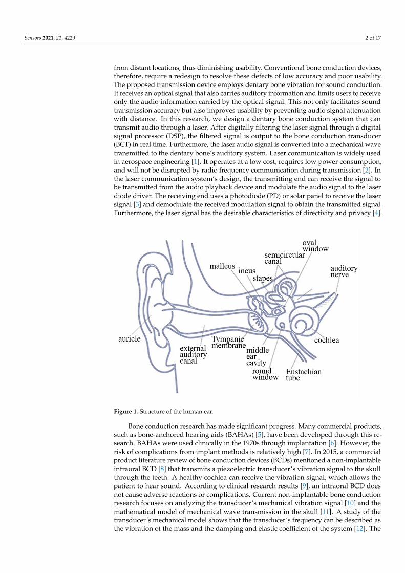
Sound is transmitted through bones. The auditory path begins with bone vibrationand passes through the inner ear via the auditory nerve to the auditory center, withoutpassing through the outer and middle ear. Sound is thus transmitted directly to the cochleain the inner ear through the bone. This auditory path’s major function is to cause thecochlear wall to vibrate, allowing the inner ear sensors to receive the signal, which isthen transmitted through the auditory nerve to the auditory center in the brain, whichgenerates an auditory sensation. Figure 1 shows the structure of the human ear. Peoplewith hearing loss who have a normal auditory nerve can still utilize the bone conductionpath to receive an auditory sensation. According to domestic and foreign research onbone conduction hearing aids, such a device usually includes a signal converter electricallyconnected to a vibrator. The signal converter receives the ambient sound signal andconverts it into a corresponding electrical signal. A vibrating sheet is then driven by theelectrical signal to generate a vibration. Users would simply press the vibrating sheetagainst the bones in their middle ear area to utilize the bone as a medium to transmit thefrequency of the vibrating sheet to their cochlear structure and the auditory nerve, enablingperception of the sound received by the signal converter. However, the signal converterof a bone conduction hearing aid can receive sounds from all directions. Excessive soundsources or continual noise can prevent users from correctly receiving the target sound,resulting in low accuracy of sound transmission. Additionally, when an audio signalis transmitted through the air, its intensity attenuates with distance. Excessive distancebetween the user and the sound source can, thus, prevent smooth transmission of the audiosignal to the signal converter, and the user will, therefore, be unable to receive sounds
Sensors 2021, 21, 4229. https://doi.org/10.3390/s21124229 https://www.mdpi.com/journal/sensors
Sensors 2021, 21, 4229 2 of 17
from distant locations, thus diminishing usability. Conventional bone conduction devices,therefore, require a redesign to resolve these defects of low accuracy and poor usability.The proposed transmission device employs dentary bone vibration for sound conduction.It receives an optical signal that also carries auditory information and limits users to receiveonly the audio information carried by the optical signal. This not only facilitates soundtransmission accuracy but also improves usability by preventing audio signal attenuationwith distance. In this research, we design a dentary bone conduction system that cantransmit audio through a laser. After digitally filtering the laser signal through a digitalsignal processor (DSP), the filtered signal is output to the bone conduction transducer(BCT) in real time. Furthermore, the laser audio signal is converted into a mechanical wavetransmitted to the dentary bone’s auditory system. Laser communication is widely usedin aerospace engineering [1]. It operates at a low cost, requires low power consumption,and will not be disrupted by radio frequency communication during transmission [2]. Inthe laser communication system’s design, the transmitting end can receive the signal tobe transmitted from the audio playback device and modulate the audio signal to the laserdiode driver. The receiving end uses a photodiode (PD) or solar panel to receive the lasersignal [3] and demodulate the received modulation signal to obtain the transmitted signal.Furthermore, the laser signal has the desirable characteristics of directivity and privacy [4].
Sensors 2021, 21, x FOR PEER REVIEW 2 of 18
and the sound source can, thus, prevent smooth transmission of the audio signal to the signal converter, and the user will, therefore, be unable to receive sounds from distant locations, thus diminishing usability. Conventional bone conduction devices, therefore, require a redesign to resolve these defects of low accuracy and poor usability. The pro-posed transmission device employs dentary bone vibration for sound conduction. It re-ceives an optical signal that also carries auditory information and limits users to receive only the audio information carried by the optical signal. This not only facilitates sound transmission accuracy but also improves usability by preventing audio signal attenuation with distance. In this research, we design a dentary bone conduction system that can transmit audio through a laser. After digitally filtering the laser signal through a digital signal processor (DSP), the filtered signal is output to the bone conduction transducer (BCT) in real time. Furthermore, the laser audio signal is converted into a mechanical wave transmitted to the dentary bone’s auditory system. Laser communication is widely used in aerospace engineering [1]. It operates at a low cost, requires low power consump-tion, and will not be disrupted by radio frequency communication during transmission [2]. In the laser communication system’s design, the transmitting end can receive the sig-nal to be transmitted from the audio playback device and modulate the audio signal to the laser diode driver. The receiving end uses a photodiode (PD) or solar panel to receive the laser signal [3] and demodulate the received modulation signal to obtain the transmit-ted signal. Furthermore, the laser signal has the desirable characteristics of directivity and privacy [4].
Figure 1. Structure of the human ear.
Bone conduction research has made significant progress. Many commercial prod-ucts, such as bone-anchored hearing aids (BAHAs) [5], have been developed through this research. BAHAs were used clinically in the 1970s through implantation [6]. However, the risk of complications from implant methods is relatively high [7]. In 2015, a commercial product literature review of bone conduction devices (BCDs) mentioned a non-implanta-ble intraoral BCD [8] that transmits a piezoelectric transducer’s vibration signal to the skull through the teeth. A healthy cochlea can receive the vibration signal, which allows the patient to hear sound. According to clinical research results [9], an intraoral BCD does not cause adverse reactions or complications. Current non-implantable bone conduction research focuses on analyzing the transducer’s mechanical vibration signal [10] and the
Figure 1. Structure of the human ear.
Bone conduction research has made significant progress. Many commercial products,such as bone-anchored hearing aids (BAHAs) [5], have been developed through this re-search. BAHAs were used clinically in the 1970s through implantation [6]. However, therisk of complications from implant methods is relatively high [7]. In 2015, a commercialproduct literature review of bone conduction devices (BCDs) mentioned a non-implantableintraoral BCD [8] that transmits a piezoelectric transducer’s vibration signal to the skullthrough the teeth. A healthy cochlea can receive the vibration signal, which allows thepatient to hear sound. According to clinical research results [9], an intraoral BCD doesnot cause adverse reactions or complications. Current non-implantable bone conductionresearch focuses on analyzing the transducer’s mechanical vibration signal [10] and themathematical model of mechanical wave transmission in the skull [11]. A study of thetransducer’s mechanical model shows that the transducer’s frequency can be described asthe vibration of the mass and the damping and elastic coefficient of the system [12]. The

Sensors 2021, 21, 4229 3 of 17
study partly discusses the loss of mechanical wave transmission paths in soft tissue [13].At present, there is little discussion of the application of DSP and digital signal processingmethods in bone conduction system designs [14]. We used an intraoral BCD as the experi-mental platform for this article and describe a complete DSP realization process in additionto analyzing the dentary bone conduction system.
Our Contribution
At present, the wearer of the bone conduction device will not hear their conversationpartner’s voice on noisy occasions. That is because the microphone will receive the soundof the entire space and couple it. Our contribution is to propose and implement a dentarybone conduction system that can transmit voice through optical communication and aframework for processing the received optically transmitted voice signal through DSP. Theschematic diagram of a dentary bone conduction system applied to humans is shown inFigure 2. The advantage of our proposed dentary bone conduction system compared withother types of bone conduction is that compared with the other types of bone conductionapplication situations, dental bone conduction does not need to transmit mechanical signalsthrough the skin and soft tissues. Therefore, it does not cause mechanical signal attenuation,so the voice/sound can more clearly be heard. A laser can effectively avoid the transmissionof voice signals of the cocktail party problem. The cocktail party effect refers to the brain’sability for selective hearing. In this phenomenon, one’s auditory attention is focused on aperson’s conversation while ignoring other conversations or noises in the background. Thiseffect reveals an amazing ability in the human auditory system that allows us to conversein noisy environments. As long as the solar panel or photodiode at the receiving end has ashield so that it is not disturbed by ambient light, it can ensure that the user only hears theconversation. In signal processing, because the voice transmission is through modulationsin the laser light, we can use low-computing digital filtering algorithms running on a low-cost DSP to reduce design costs. Advanced bone conduction hearing aids can help to avoidthe cocktail party problem. It is necessary to use multiple microphones with an advancedbeamforming algorithm to remove spatial noise, making the design more complex. Thecost is higher than that of general bone conduction hearing aids. Therefore, our researchprovides a low-cost and easy-to-design dentary bone conduction system framework foroptical communication to transmit voice with the goal of being a new research field inbone conduction in the future. The performance comparison of voice signal wirelesstransmission methods is shown in Table 1. We also compare the performance differencebetween our dentary bone conduction device and other bone conduction devices, which isshown in Table 2.
Table 1. The performance comparison of voice signal wireless transmission method.
Laser RF
Radio frequency interference No Yes
Transport security High (cannot be sniffed) Low (can be sniffed)
The computational complexity of signalprocessing algorithms Simple (digital filter)
Complex (decoding algorithms,arithmetic coding, error-correcting code,
FFT, digital filter)
Cost of analog front end Low (transimpedance amplifier,gain amplifier)
High (low-noise amplifier,voltage-controlled oscillator, mixer)
Sensors 2021, 21, 4229 4 of 17Sensors 2021, 21, x FOR PEER REVIEW 4 of 18
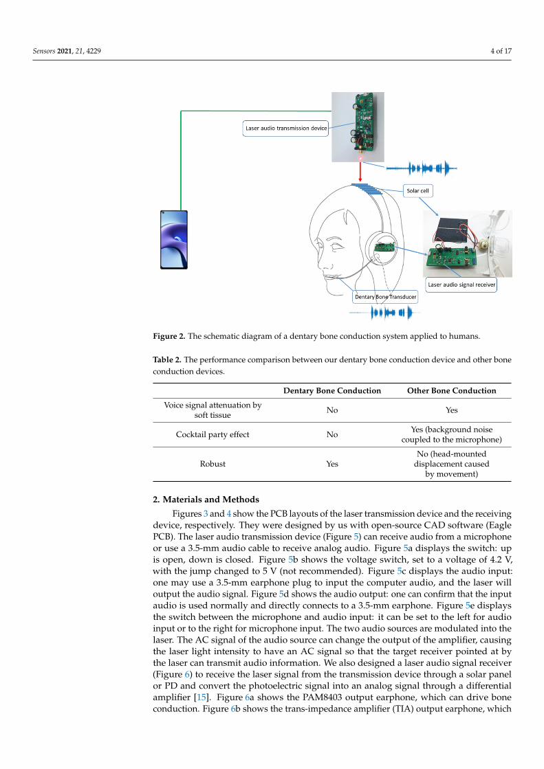
Figure 2. The schematic diagram of a dentary bone conduction system applied to humans.
Table 1. The performance comparison of voice signal wireless transmission method.
Laser RF Radio frequency interference No Yes
Transport security High (cannot be sniffed) Low (can be sniffed)
The computational complex-ity of signal processing algo-
rithms Simple (digital filter)
Complex (decoding algo-rithms, arithmetic coding, er-ror-correcting code, FFT, digi-
tal filter)
Cost of analog front end Low (transimpedance am-
plifier, gain amplifier)
High (low-noise amplifier, voltage-controlled oscillator,
mixer)
Table 2. The performance comparison between our dentary bone conduction device and other bone conduction devices.
Dentary Bone Conduction Other Bone Conduction Voice signal attenuation by
soft tissue No Yes
Cocktail party effect No Yes (background noise cou-
pled to the microphone)
Robust Yes No (head-mounted displace-ment caused by movement)
2. Materials and Methods Figures 3 and 4 show the PCB layouts of the laser transmission device and the receiv-
ing device, respectively. They were designed by us with open-source CAD software (Ea-gle PCB). The laser audio transmission device (Figure 5) can receive audio from a micro-phone or use a 3.5-mm audio cable to receive analog audio. Figure 5a displays the switch: up is open, down is closed. Figure 5b shows the voltage switch, set to a voltage of 4.2 V, with the jump changed to 5 V (not recommended). Figure 5c displays the audio input: one may use a 3.5-mm earphone plug to input the computer audio, and the laser will output
Figure 2. The schematic diagram of a dentary bone conduction system applied to humans.
Table 2. The performance comparison between our dentary bone conduction device and other boneconduction devices.
Dentary Bone Conduction Other Bone Conduction
Voice signal attenuation bysoft tissue No Yes
Cocktail party effect No Yes (background noisecoupled to the microphone)
Robust YesNo (head-mounted
displacement causedby movement)
2. Materials and Methods
Figures 3 and 4 show the PCB layouts of the laser transmission device and the receivingdevice, respectively. They were designed by us with open-source CAD software (EaglePCB). The laser audio transmission device (Figure 5) can receive audio from a microphoneor use a 3.5-mm audio cable to receive analog audio. Figure 5a displays the switch: upis open, down is closed. Figure 5b shows the voltage switch, set to a voltage of 4.2 V,with the jump changed to 5 V (not recommended). Figure 5c displays the audio input:one may use a 3.5-mm earphone plug to input the computer audio, and the laser willoutput the audio signal. Figure 5d shows the audio output: one can confirm that the inputaudio is used normally and directly connects to a 3.5-mm earphone. Figure 5e displaysthe switch between the microphone and audio input: it can be set to the left for audioinput or to the right for microphone input. The two audio sources are modulated into thelaser. The AC signal of the audio source can change the output of the amplifier, causingthe laser light intensity to have an AC signal so that the target receiver pointed at bythe laser can transmit audio information. We also designed a laser audio signal receiver(Figure 6) to receive the laser signal from the transmission device through a solar panelor PD and convert the photoelectric signal into an analog signal through a differentialamplifier [15]. Figure 6a shows the PAM8403 output earphone, which can drive boneconduction. Figure 6b shows the trans-impedance amplifier (TIA) output earphone, which

Sensors 2021, 21, 4229 5 of 17
can be used to listen to the sound transmitted by the solar panel or photodiode. Figure 6cdisplays the power switch, which turns on and off. Figure 6d displays the input of thepiezoelectric sensor. The output signal of the differential amplifier can be input to a 3-wattD-class power amplifier. The power amplifier can directly drive the BCT or input the 12-bitanalog into the microprocessor’s digital converter (ADC).
Sensors 2021, 21, x FOR PEER REVIEW 5 of 18
the audio signal. Figure 5d shows the audio output: one can confirm that the input audio is used normally and directly connects to a 3.5-mm earphone. Figure 5e displays the switch between the microphone and audio input: it can be set to the left for audio input or to the right for microphone input. The two audio sources are modulated into the laser. The AC signal of the audio source can change the output of the amplifier, causing the laser light intensity to have an AC signal so that the target receiver pointed at by the laser can transmit audio information. We also designed a laser audio signal receiver (Figure 6) to receive the laser signal from the transmission device through a solar panel or PD and con-vert the photoelectric signal into an analog signal through a differential amplifier [15]. Figure 6a shows the PAM8403 output earphone, which can drive bone conduction. Figure 6b shows the trans-impedance amplifier (TIA) output earphone, which can be used to listen to the sound transmitted by the solar panel or photodiode. Figure 6c displays the power switch, which turns on and off. Figure 6d displays the input of the piezoelectric sensor. The output signal of the differential amplifier can be input to a 3-watt D-class power amplifier. The power amplifier can directly drive the BCT or input the 12-bit analog into the microprocessor’s digital converter (ADC).
Figure 3. The PCB layout of the laser transmission device.
Figure 4. The PCB layout of the laser receiving device.
Figure 3. The PCB layout of the laser transmission device.
Sensors 2021, 21, x FOR PEER REVIEW 5 of 18
the audio signal. Figure 5d shows the audio output: one can confirm that the input audio is used normally and directly connects to a 3.5-mm earphone. Figure 5e displays the switch between the microphone and audio input: it can be set to the left for audio input or to the right for microphone input. The two audio sources are modulated into the laser. The AC signal of the audio source can change the output of the amplifier, causing the laser light intensity to have an AC signal so that the target receiver pointed at by the laser can transmit audio information. We also designed a laser audio signal receiver (Figure 6) to receive the laser signal from the transmission device through a solar panel or PD and con-vert the photoelectric signal into an analog signal through a differential amplifier [15]. Figure 6a shows the PAM8403 output earphone, which can drive bone conduction. Figure 6b shows the trans-impedance amplifier (TIA) output earphone, which can be used to listen to the sound transmitted by the solar panel or photodiode. Figure 6c displays the power switch, which turns on and off. Figure 6d displays the input of the piezoelectric sensor. The output signal of the differential amplifier can be input to a 3-watt D-class power amplifier. The power amplifier can directly drive the BCT or input the 12-bit analog into the microprocessor’s digital converter (ADC).
Figure 3. The PCB layout of the laser transmission device.
Figure 4. The PCB layout of the laser receiving device. Figure 4. The PCB layout of the laser receiving device.
The digital filtering algorithm running on the microprocessor processes the audio.The signal is processed before it is input to the power amplifier so that the BCT canoutput a cleaner sound signal to the user. Figure 7 shows the system architecture. Thetransmission of audio by the laser can differ from mechanical wave transmission, and itis not easily affected by the physical environment. Moreover, the laser light intensity ata distance of a few meters is relatively small, which can be beneficial for the transmittedaudio. The signal-to-noise ratio makes it easier to improve the BCT’s audio quality throughsignal processing.
2.1. Laser Audio Transmitter and Receiver
The laser audio transmission device can modulate the audio signal to the laser throughthe LM358, a chip that encapsulates two operational amplifiers. The device can also connectto the audio playback device through the 3.5-mm audio cable, and the audio can be inputinto the positive terminal of the amplifier (Figure 8). Therefore, the amplifier’s outputvoltage will output the same amplitude as the AC signal of the input audio, and the inputof the negative terminal determines the other part of the output voltage. The DC level ofthe amplifier’s output voltage can be adjusted by the negative terminal feedback resistor’spotentiometer. We also designed a microphone amplifier circuit (Figure 9) that can receivethe microphone’s input voice signal to facilitate communication between healthy people
Sensors 2021, 21, 4229 6 of 17
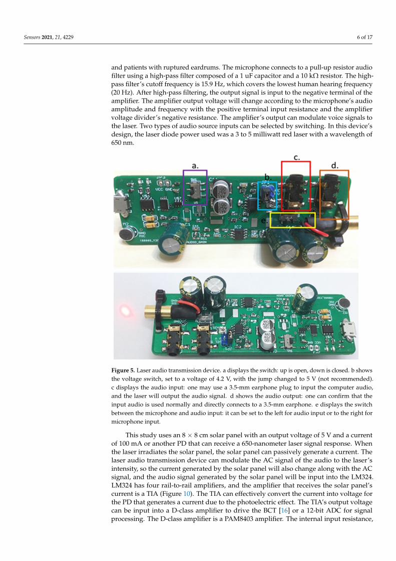
and patients with ruptured eardrums. The microphone connects to a pull-up resistor audiofilter using a high-pass filter composed of a 1 uF capacitor and a 10 kΩ resistor. The high-pass filter’s cutoff frequency is 15.9 Hz, which covers the lowest human hearing frequency(20 Hz). After high-pass filtering, the output signal is input to the negative terminal of theamplifier. The amplifier output voltage will change according to the microphone’s audioamplitude and frequency with the positive terminal input resistance and the amplifiervoltage divider’s negative resistance. The amplifier’s output can modulate voice signals tothe laser. Two types of audio source inputs can be selected by switching. In this device’sdesign, the laser diode power used was a 3 to 5 milliwatt red laser with a wavelength of650 nm.
Sensors 2021, 21, x FOR PEER REVIEW 6 of 18
Figure 5. Laser audio transmission device. a displays the switch: up is open, down is closed. b shows the voltage switch, set to a voltage of 4.2 V, with the jump changed to 5 V (not recommended). c displays the audio input: one may use a 3.5-mm earphone plug to input the computer audio, and the laser will output the audio signal. d shows the au-dio output: one can confirm that the input audio is used normally and directly connects to a 3.5-mm earphone. e displays the switch between the microphone and audio input: it can be set to the left for audio input or to the right for microphone input.
The digital filtering algorithm running on the microprocessor processes the audio. The signal is processed before it is input to the power amplifier so that the BCT can output a cleaner sound signal to the user. Figure 7 shows the system architecture. The transmis-sion of audio by the laser can differ from mechanical wave transmission, and it is not easily affected by the physical environment. Moreover, the laser light intensity at a dis-tance of a few meters is relatively small, which can be beneficial for the transmitted audio. The signal-to-noise ratio makes it easier to improve the BCT’s audio quality through signal processing.
Figure 5. Laser audio transmission device. a displays the switch: up is open, down is closed. b showsthe voltage switch, set to a voltage of 4.2 V, with the jump changed to 5 V (not recommended).c displays the audio input: one may use a 3.5-mm earphone plug to input the computer audio,and the laser will output the audio signal. d shows the audio output: one can confirm that theinput audio is used normally and directly connects to a 3.5-mm earphone. e displays the switchbetween the microphone and audio input: it can be set to the left for audio input or to the right formicrophone input.
This study uses an 8 × 8 cm solar panel with an output voltage of 5 V and a currentof 100 mA or another PD that can receive a 650-nanometer laser signal response. Whenthe laser irradiates the solar panel, the solar panel can passively generate a current. Thelaser audio transmission device can modulate the AC signal of the audio to the laser’sintensity, so the current generated by the solar panel will also change along with the ACsignal, and the audio signal generated by the solar panel will be input into the LM324.LM324 has four rail-to-rail amplifiers, and the amplifier that receives the solar panel’scurrent is a TIA (Figure 10). The TIA can effectively convert the current into voltage forthe PD that generates a current due to the photoelectric effect. The TIA’s output voltagecan be input into a D-class amplifier to drive the BCT [16] or a 12-bit ADC for signalprocessing. The D-class amplifier is a PAM8403 amplifier. The internal input resistance,

Sensors 2021, 21, 4229 7 of 17
Ri, of PAM8403 is 18 kΩ, and the feedback resistance is 142 kΩ. The experimental settinghas an external input resistance of 10 kΩ, and the close-gain calculation formula is 20 ×log (2 × (142 kΩ/[18 kΩ + 10 kΩ])), which equals 31 dB [17]. PAM8403 can amplify theTIA’s voltage output and drive the BCT, and the BCT can convert the audio AC signals intomechanical waves. The BCT can transmit audio to the acoustic nerve as mechanical waveswhen it contacts the dentary bone.
Sensors 2021, 21, x FOR PEER REVIEW 7 of 18
Figure 6. Laser audio signal receiver. a shows the PAM8403 output earphone, which can drive bone conduction. b shows the trans-impedance amplifier (TIA) output earphone, which can be used to listen to the sound transmitted by the solar panel or photodiode. c displays the power switch, which turns on and off. d displays the input of the piezoelec-tric sensor.
Figure 6. Laser audio signal receiver. a shows the PAM8403 output earphone, which can drive boneconduction. b shows the trans-impedance amplifier (TIA) output earphone, which can be used tolisten to the sound transmitted by the solar panel or photodiode. c displays the power switch, whichturns on and off. d displays the input of the piezoelectric sensor.

Sensors 2021, 21, 4229 8 of 17Sensors 2021, 21, x FOR PEER REVIEW 8 of 18
Figure 7. System architecture.
2.1. Laser Audio Transmitter and Receiver The laser audio transmission device can modulate the audio signal to the laser
through the LM358, a chip that encapsulates two operational amplifiers. The device can also connect to the audio playback device through the 3.5-mm audio cable, and the audio can be input into the positive terminal of the amplifier (Figure 8). Therefore, the ampli-fier’s output voltage will output the same amplitude as the AC signal of the input audio, and the input of the negative terminal determines the other part of the output voltage. The DC level of the amplifier’s output voltage can be adjusted by the negative terminal feedback resistor’s potentiometer. We also designed a microphone amplifier circuit (Fig-ure 9) that can receive the microphone’s input voice signal to facilitate communication between healthy people and patients with ruptured eardrums. The microphone connects to a pull-up resistor audio filter using a high-pass filter composed of a 1 uF capacitor and a 10 kΩ resistor. The high-pass filter’s cutoff frequency is 15.9 Hz, which covers the lowest human hearing frequency (20 Hz). After high-pass filtering, the output signal is input to the negative terminal of the amplifier. The amplifier output voltage will change according to the microphone’s audio amplitude and frequency with the positive terminal input re-sistance and the amplifier voltage divider’s negative resistance. The amplifier’s output can modulate voice signals to the laser. Two types of audio source inputs can be selected by switching. In this device’s design, the laser diode power used was a 3 to 5 milliwatt red laser with a wavelength of 650 nm.
Figure 8. The audio signal input circuit of the laser audio transmission device.
Figure 7. System architecture.
Sensors 2021, 21, x FOR PEER REVIEW 8 of 18
Figure 7. System architecture.
2.1. Laser Audio Transmitter and Receiver The laser audio transmission device can modulate the audio signal to the laser
through the LM358, a chip that encapsulates two operational amplifiers. The device can also connect to the audio playback device through the 3.5-mm audio cable, and the audio can be input into the positive terminal of the amplifier (Figure 8). Therefore, the ampli-fier’s output voltage will output the same amplitude as the AC signal of the input audio, and the input of the negative terminal determines the other part of the output voltage. The DC level of the amplifier’s output voltage can be adjusted by the negative terminal feedback resistor’s potentiometer. We also designed a microphone amplifier circuit (Fig-ure 9) that can receive the microphone’s input voice signal to facilitate communication between healthy people and patients with ruptured eardrums. The microphone connects to a pull-up resistor audio filter using a high-pass filter composed of a 1 uF capacitor and a 10 kΩ resistor. The high-pass filter’s cutoff frequency is 15.9 Hz, which covers the lowest human hearing frequency (20 Hz). After high-pass filtering, the output signal is input to the negative terminal of the amplifier. The amplifier output voltage will change according to the microphone’s audio amplitude and frequency with the positive terminal input re-sistance and the amplifier voltage divider’s negative resistance. The amplifier’s output can modulate voice signals to the laser. Two types of audio source inputs can be selected by switching. In this device’s design, the laser diode power used was a 3 to 5 milliwatt red laser with a wavelength of 650 nm.
Figure 8. The audio signal input circuit of the laser audio transmission device. Figure 8. The audio signal input circuit of the laser audio transmission device.
Sensors 2021, 21, x FOR PEER REVIEW 9 of 18
Figure 9. The microphone circuit of the laser audio transmission device.
This study uses an 8 × 8 cm solar panel with an output voltage of 5 V and a current of 100 mA or another PD that can receive a 650-nanometer laser signal response. When the laser irradiates the solar panel, the solar panel can passively generate a current. The laser audio transmission device can modulate the AC signal of the audio to the laser’s intensity, so the current generated by the solar panel will also change along with the AC signal, and the audio signal generated by the solar panel will be input into the LM324. LM324 has four rail-to-rail amplifiers, and the amplifier that receives the solar panel’s current is a TIA (Figure 10). The TIA can effectively convert the current into voltage for the PD that generates a current due to the photoelectric effect. The TIA’s output voltage can be input into a D-class amplifier to drive the BCT [16] or a 12-bit ADC for signal pro-cessing. The D-class amplifier is a PAM8403 amplifier. The internal input resistance, Ri, of PAM8403 is 18 kΩ, and the feedback resistance is 142 kΩ. The experimental setting has an external input resistance of 10 kΩ, and the close-gain calculation formula is 20 * log (2 * (142 kΩ/[18 kΩ + 10 kΩ])), which equals 31 dB [17]. PAM8403 can amplify the TIA’s voltage output and drive the BCT, and the BCT can convert the audio AC signals into mechanical waves. The BCT can transmit audio to the acoustic nerve as mechanical waves when it contacts the dentary bone.
Figure 10. The trans-impedance amplifier of the laser audio signal receiver circuit.
Figure 9. The microphone circuit of the laser audio transmission device.

Sensors 2021, 21, 4229 9 of 17
Sensors 2021, 21, x FOR PEER REVIEW 9 of 18
Figure 9. The microphone circuit of the laser audio transmission device.
This study uses an 8 × 8 cm solar panel with an output voltage of 5 V and a current of 100 mA or another PD that can receive a 650-nanometer laser signal response. When the laser irradiates the solar panel, the solar panel can passively generate a current. The laser audio transmission device can modulate the AC signal of the audio to the laser’s intensity, so the current generated by the solar panel will also change along with the AC signal, and the audio signal generated by the solar panel will be input into the LM324. LM324 has four rail-to-rail amplifiers, and the amplifier that receives the solar panel’s current is a TIA (Figure 10). The TIA can effectively convert the current into voltage for the PD that generates a current due to the photoelectric effect. The TIA’s output voltage can be input into a D-class amplifier to drive the BCT [16] or a 12-bit ADC for signal pro-cessing. The D-class amplifier is a PAM8403 amplifier. The internal input resistance, Ri, of PAM8403 is 18 kΩ, and the feedback resistance is 142 kΩ. The experimental setting has an external input resistance of 10 kΩ, and the close-gain calculation formula is 20 * log (2 * (142 kΩ/[18 kΩ + 10 kΩ])), which equals 31 dB [17]. PAM8403 can amplify the TIA’s voltage output and drive the BCT, and the BCT can convert the audio AC signals into mechanical waves. The BCT can transmit audio to the acoustic nerve as mechanical waves when it contacts the dentary bone.
Figure 10. The trans-impedance amplifier of the laser audio signal receiver circuit. Figure 10. The trans-impedance amplifier of the laser audio signal receiver circuit.
This study uses piezoelectric ceramics to receive the mechanical wave generatedby the BCT to measure the feedback signal [18]. The mechanical wave will cause thepiezoelectric material to undergo a piezoelectric effect so that the piezoelectric ceramiccan output mV-level voltage. For this analog front-end (AFE) design, we used threeamplifiers of LM324, pulled down the positive pole of the piezoelectric ceramic to a 4.7 mΩresistor, and input the positive terminal (Figure 11) of the first-stage voltage follower. Thevoltage follower’s input resistance is infinite, and the zero output resistances can ensurethe complete input of tiny piezoelectric signals. The second-stage amplifier is a feed-forward amplifier (Figure 12) with a 19-times gain. It can amplify the voltage follower’smV-level signal output to increase the signal-to-noise ratio (SNR). The last-stage amplifieris a low-pass filter (Figure 13) with a Sallen–Key structure. The cutoff frequency is 72 kHz.Although the feed-forward amplifier’s output amplifies the audio’s AC signal, it alsoamplifies the noise. Therefore, we designed the low-pass filter to ensure that the upperlimit of the frequency covering human hearing is 44.1 kHz so that this design is in line withthe frequency range we want to analyze. The low-pass filter output sampled a 12-bit ADCat a frequency of 44.1 kHz and was analyzed using a digital signal processing technique.
Sensors 2021, 21, x FOR PEER REVIEW 10 of 18
This study uses piezoelectric ceramics to receive the mechanical wave generated by the BCT to measure the feedback signal [18]. The mechanical wave will cause the piezoe-lectric material to undergo a piezoelectric effect so that the piezoelectric ceramic can out-put mV-level voltage. For this analog front-end (AFE) design, we used three amplifiers of LM324, pulled down the positive pole of the piezoelectric ceramic to a 4.7 mΩ resistor, and input the positive terminal (Figure 11) of the first-stage voltage follower. The voltage follower’s input resistance is infinite, and the zero output resistances can ensure the com-plete input of tiny piezoelectric signals. The second-stage amplifier is a feed-forward am-plifier (Figure 12) with a 19-times gain. It can amplify the voltage follower’s mV-level sig-nal output to increase the signal-to-noise ratio (SNR). The last-stage amplifier is a low-pass filter (Figure 13) with a Sallen–Key structure. The cutoff frequency is 72 kHz. Alt-hough the feed-forward amplifier’s output amplifies the audio’s AC signal, it also ampli-fies the noise. Therefore, we designed the low-pass filter to ensure that the upper limit of the frequency covering human hearing is 44.1 kHz so that this design is in line with the frequency range we want to analyze. The low-pass filter output sampled a 12-bit ADC at a frequency of 44.1 kHz and was analyzed using a digital signal processing technique.
Figure 11. The voltage follower of the laser audio signal receiver circuit.
Figure 12. The feed-forward amplifier of the laser audio signal receiver circuit.
Figure 11. The voltage follower of the laser audio signal receiver circuit.

Sensors 2021, 21, 4229 10 of 17
Sensors 2021, 21, x FOR PEER REVIEW 10 of 18
This study uses piezoelectric ceramics to receive the mechanical wave generated by the BCT to measure the feedback signal [18]. The mechanical wave will cause the piezoe-lectric material to undergo a piezoelectric effect so that the piezoelectric ceramic can out-put mV-level voltage. For this analog front-end (AFE) design, we used three amplifiers of LM324, pulled down the positive pole of the piezoelectric ceramic to a 4.7 mΩ resistor, and input the positive terminal (Figure 11) of the first-stage voltage follower. The voltage follower’s input resistance is infinite, and the zero output resistances can ensure the com-plete input of tiny piezoelectric signals. The second-stage amplifier is a feed-forward am-plifier (Figure 12) with a 19-times gain. It can amplify the voltage follower’s mV-level sig-nal output to increase the signal-to-noise ratio (SNR). The last-stage amplifier is a low-pass filter (Figure 13) with a Sallen–Key structure. The cutoff frequency is 72 kHz. Alt-hough the feed-forward amplifier’s output amplifies the audio’s AC signal, it also ampli-fies the noise. Therefore, we designed the low-pass filter to ensure that the upper limit of the frequency covering human hearing is 44.1 kHz so that this design is in line with the frequency range we want to analyze. The low-pass filter output sampled a 12-bit ADC at a frequency of 44.1 kHz and was analyzed using a digital signal processing technique.
Figure 11. The voltage follower of the laser audio signal receiver circuit.
Figure 12. The feed-forward amplifier of the laser audio signal receiver circuit. Figure 12. The feed-forward amplifier of the laser audio signal receiver circuit.
Sensors 2021, 21, x FOR PEER REVIEW 11 of 18
Figure 13. The low-pass filter with a Sallen–Key type of laser audio signal receiver circuit.
We used an STM32F407 processor [19] integrated with a 12-bit ADC to perform laser audio sampling (Figure 14). STM32F407 can transmit audio to a computer in digital pack-ets using the USB audio class protocol of USB2.0 for analysis. This function is similar to that of a sound card. We receive the TIA’s output for microphone recording to analyze the audio quality transmitted by the laser. We also received the low-pass filter’s output to analyze the mechanical wave output by the BCT directly measured by the piezoelectric ceramic. We then analyzed whether the output of the BCT converted from electrical sig-nals into mechanical waves was distorted. We will discuss the results in Section 4.
Figure 14. STM32F4-Discovery and 12-bit ADC.
Figure 13. The low-pass filter with a Sallen–Key type of laser audio signal receiver circuit.
We used an STM32F407 processor [19] integrated with a 12-bit ADC to perform laseraudio sampling (Figure 14). STM32F407 can transmit audio to a computer in digital packetsusing the USB audio class protocol of USB2.0 for analysis. This function is similar to that ofa sound card. We receive the TIA’s output for microphone recording to analyze the audioquality transmitted by the laser. We also received the low-pass filter’s output to analyzethe mechanical wave output by the BCT directly measured by the piezoelectric ceramic.We then analyzed whether the output of the BCT converted from electrical signals intomechanical waves was distorted. We will discuss the results in Section 4.
2.2. Analog Front End
This section explains how we set up an analog-to-digital conversion system for receiv-ing laser audio analog signals. After receiving the audio from the transmitter, the laseraudio receiver outputted the analog voltage signal via the TIA. We then used the integrated12-bit SAR-ADC ARM SoC to receive analog signals and converted them into quantizeddigital signals.

Sensors 2021, 21, 4229 11 of 17
Sensors 2021, 21, x FOR PEER REVIEW 11 of 18
Figure 13. The low-pass filter with a Sallen–Key type of laser audio signal receiver circuit.
We used an STM32F407 processor [19] integrated with a 12-bit ADC to perform laser audio sampling (Figure 14). STM32F407 can transmit audio to a computer in digital pack-ets using the USB audio class protocol of USB2.0 for analysis. This function is similar to that of a sound card. We receive the TIA’s output for microphone recording to analyze the audio quality transmitted by the laser. We also received the low-pass filter’s output to analyze the mechanical wave output by the BCT directly measured by the piezoelectric ceramic. We then analyzed whether the output of the BCT converted from electrical sig-nals into mechanical waves was distorted. We will discuss the results in Section 4.
Figure 14. STM32F4-Discovery and 12-bit ADC. Figure 14. STM32F4-Discovery and 12-bit ADC.
2.2.1. Analog to Digital Converter (ADC)
The STM32F407 processor is a platform for digital signal processing. The processorintegrates a 12-bit SAR-ADC [20], which can quantize audio from 0 to 3.3 (analog voltage)to 0 to 4095 (digital signal). To cover the audio frequency range perceptible to the humanauditory nerve, we set the processor to have a sampling rate of 44,100 Hz for the ADC.We set the timer interrupt period of the processor to 1/44,100 s. When the timer interruptwas triggered, direct memory access was triggered to sample the ADC’s analog signaland convert it to a digital value of 0 to 4095. The flowchart is shown in Figure 15. TheSTM32F407 pins PC5 and PC4 connect to the TIA output and low-pass filter output of thelaser audio receiver. It can convert analog signals into digital signals, thereby providing afeasible means for laser audio signal processing.
Sensors 2021, 21, x FOR PEER REVIEW 12 of 18
2.2. Analog Front End This section explains how we set up an analog-to-digital conversion system for re-
ceiving laser audio analog signals. After receiving the audio from the transmitter, the laser audio receiver outputted the analog voltage signal via the TIA. We then used the inte-grated 12-bit SAR-ADC ARM SoC to receive analog signals and converted them into quantized digital signals.
2.2.1. Analog to Digital Converter (ADC) The STM32F407 processor is a platform for digital signal processing. The processor
integrates a 12-bit SAR-ADC [20], which can quantize audio from 0 to 3.3 (analog voltage) to 0 to 4095 (digital signal). To cover the audio frequency range perceptible to the human auditory nerve, we set the processor to have a sampling rate of 44,100 Hz for the ADC. We set the timer interrupt period of the processor to 1/44,100 s. When the timer interrupt was triggered, direct memory access was triggered to sample the ADC’s analog signal and convert it to a digital value of 0 to 4095. The flowchart is shown in Figure 15. The STM32F407 pins PC5 and PC4 connect to the TIA output and low-pass filter output of the laser audio receiver. It can convert analog signals into digital signals, thereby providing a feasible means for laser audio signal processing.
Figure 15. Digital signal processing flowchart.
2.2.2. Digital-to-Analog Converter (DAC) After the laser audio converts the analog signal to a digital signal, we can use digital
signal processing algorithms to filter the sound signal, thereby improving the audio qual-ity or strengthening the audio frequency band that we wish users to hear. It must trans-form from a digital signal to an analog signal after processing to output the digital signal to the BCT. We used the 12-bit DAC [21] integrated inside the STM32F407 to convert the digital signal processed by the digital filtering algorithm from 0 to 4095, to 0 to 3.3 analog voltage. Furthermore, we had to output to the D-class amplifier to drive the BCT to en-hance the audio output. The connection method for DAC and the D-class amplifier is shown in Figure 16.
Figure 15. Digital signal processing flowchart.

Sensors 2021, 21, 4229 12 of 17
2.2.2. Digital-to-Analog Converter (DAC)
After the laser audio converts the analog signal to a digital signal, we can use digitalsignal processing algorithms to filter the sound signal, thereby improving the audio qualityor strengthening the audio frequency band that we wish users to hear. It must transformfrom a digital signal to an analog signal after processing to output the digital signal tothe BCT. We used the 12-bit DAC [21] integrated inside the STM32F407 to convert thedigital signal processed by the digital filtering algorithm from 0 to 4095, to 0 to 3.3 analogvoltage. Furthermore, we had to output to the D-class amplifier to drive the BCT to enhancethe audio output. The connection method for DAC and the D-class amplifier is shownin Figure 16.
Sensors 2021, 21, x FOR PEER REVIEW 13 of 18
Figure 16. Connection between the laser audio receiver and the STM32F407 processor.
3. DSP Algorithm Design This section explains the digital signal processing method of laser audio signals. To
improve the audio quality output by the BCT, we used STM32F407 and a 12-bit ADC to sample the TIA amplifier’s work at the audio receiver. The filter algorithm runs in the STM32F407 processor to filter the laser audio signal before the DAC outputs the filtered signal. A finite impulse response (FIR) filter is a stable digital filtering algorithm, and the filter coefficients can be designed through simulation software. Using the frequency re-sponse and window function designed by simulation software [22], the coefficient can be generated after the product.
Furthermore, the time-domain signal and the coefficient are convoluted (Equation (1)) so that the filtered time-domain signal can be obtained. The FIR filter algorithm can run on the STM32F407 processor in real time because of its stability and limited length. After the received laser audio is processed in real time, the DAC is output to the PAM8403 to drive the BCT to produce clearer audio.
1
0[ ] [ ]
N
kk
y n b x n k−
=
= ⋅ − (1)
where is the signal before filtering, is the filtered signal, is a filter coeffi-cient.
To design an FIR filter, we determined the signal sampling rate and filter cutoff fre-quency. We calculated the frequency response and window function (the coefficients) ac-cording to different FIR filter types and filter lengths. We used a band-pass filter (Equation (2)) for frequency response and set the cutoff frequency fc1 to 200 Hz and fc2 to 3000 Hz. This range covers the frequency range of general adult speech [23,24]; ωc1 and ωc2 are band-pass filter cutoff frequencies, fc1 and fc2, converted to the transition frequency [25], which needs to be divided by the sampling rate of the ADC 44,100 Hz (Equation (3)). We
Figure 16. Connection between the laser audio receiver and the STM32F407 processor.
3. DSP Algorithm Design
This section explains the digital signal processing method of laser audio signals. Toimprove the audio quality output by the BCT, we used STM32F407 and a 12-bit ADC tosample the TIA amplifier’s work at the audio receiver. The filter algorithm runs in theSTM32F407 processor to filter the laser audio signal before the DAC outputs the filteredsignal. A finite impulse response (FIR) filter is a stable digital filtering algorithm, andthe filter coefficients can be designed through simulation software. Using the frequencyresponse and window function designed by simulation software [22], the coefficient can begenerated after the product.
Furthermore, the time-domain signal and the coefficient are convoluted (Equation (1))so that the filtered time-domain signal can be obtained. The FIR filter algorithm can run onthe STM32F407 processor in real time because of its stability and limited length. After the

Sensors 2021, 21, 4229 13 of 17
received laser audio is processed in real time, the DAC is output to the PAM8403 to drivethe BCT to produce clearer audio.
y[n] =N−1
∑k=0
bk · x[n− k] (1)
where x[n] is the signal before filtering, y[n] is the filtered signal, bk is a filter coefficient.To design an FIR filter, we determined the signal sampling rate and filter cutoff fre-
quency. We calculated the frequency response and window function (the coefficients)according to different FIR filter types and filter lengths. We used a band-pass filter(Equation (2)) for frequency response and set the cutoff frequency fc1 to 200 Hz and fc2 to3000 Hz. This range covers the frequency range of general adult speech [23,24]; ωc1 and ωc2are band-pass filter cutoff frequencies, fc1 and fc2, converted to the transition frequency [25],which needs to be divided by the sampling rate of the ADC 44,100 Hz (Equation (3)). Weused the hamming window (Equation (4)) for the window function, and the a0 and a1parameters were set to 0.54 and 0.46, respectively [26]. Then, we used the product windowfunctions and frequency response (Equation (5)) to obtain the filter coefficient b[k]. Finally,we convolved the input time-domain signal x[n] and the filter coefficient b[k] to obtain thefiltered signal y[n].
hd[n] =
sin(ωc2(n−N))
π(n−N)− sin(ωc1(n−N))
π(n−N); n 6= N
ωc2−ωc1π ; n = N
2
(2)
ωc1 = fc11fs
; ωc2 = fc21fs
; fs = 44,100 Hz (3)
w[n] = 0.54− 0.46 cos(2πn
N); 0 ≤ n ≤ N (4)
b[n] = w[n] · hd[n]; 0 ≤ n ≤ N − 1 (5)
4. Result and Analysis
In this section, we analyze the output signal of the TIA of the laser audio receiverdevice and the signal output after DSP filtering and compare the original signal of theLM358 amplifier of the laser audio transmitter. After the signal was normalized, we usedthe signal-to-noise ratio (SNR) (Equation (6)) function to analyze the difference betweenthe audio quality transmitted by the laser and the audio quality filtered by the DSP.
SNR = 20 log 10(SN) (6)
where S is the amplitude of the raw signal before the laser transmission and N is thereceived noise of the raw signal.
Result Analysis
We used the voice in the CMU ARCTIC database as the standard audio signal for laseraudio transmission in this study. This audio set is an open-source database [27] recordedby the Language Technologies Institute at Carnegie Mellon University for language tech-nologies research. We selected the arctic_a0223.wav sequence from the cmu_us_awb_arcticgroup in the database as the standard audio source.
Our experiment is in a meeting room with fluorescent lights (60 Hz frequency as theperiodicity of the mains electricity supply) on. We use the laser audio transmitter sourceas the signal source for SNR calculation. Because there is a time difference between thesignal transmitted by the laser and the signal at the receiver, the digital filtering of theDSP will cause a phase shift. We process the signal from the transmitter and the receiverwith the alignsignals method of MATLAB to ensure the consistency of the SNR calculation.

Sensors 2021, 21, 4229 14 of 17
For the BCT output signal, the same method was used to process the SNR calculation andcompare the SNR between the BCT output signal that uses DSP with digital filtering andthe unfiltered BCT output signal.
Figure 17 shows the output signal of the TIA and the signal filtered by DSP. Theupper signal of Figure 17 is unfiltered. The audio output by the TIA sounds like highfrequency and noise to the human ear, and it is impossible to hear the reading content ofthe standard audio source. The bandpass filter filtered the lower signal of Figure 17, and asignal exceeding 100 Hz to 10 kHz was filtered out. The high-frequency noise reduced thefiltered signal, and the SNR was improved compared with that before and after filtering.The DSP output audio can represent the reading content in the standard audio source.
Sensors 2021, 21, x FOR PEER REVIEW 15 of 18
filtered signal, and the SNR was improved compared with that before and after filtering. The DSP output audio can represent the reading content in the standard audio source.
Figure 17. Time−domain signal of TIA and DSP output.
Figure 18 shows that the piezoelectric sensor received the vibration signal of the BCT. The upper panel of Figure 18 shows that the TIA signal directly outputted the BCT’s vi-bration signal without being filtered by the DSP. The lower panel of Figure 18 shows the output of the bone conduction after being filtered by the DSP. It shows that the vibration signal of the BCT output by the DSP is cleaner and noise free. The vibration signal of the BCT output by the DSP also has a higher SNR compared to the vibration signal of the BCT output by the TIA. It is consistent with the SNR trend in Figure 17.
Figure 17. Time−domain signal of TIA and DSP output.
Figure 18 shows that the piezoelectric sensor received the vibration signal of theBCT. The upper panel of Figure 18 shows that the TIA signal directly outputted the BCT’svibration signal without being filtered by the DSP. The lower panel of Figure 18 shows theoutput of the bone conduction after being filtered by the DSP. It shows that the vibrationsignal of the BCT output by the DSP is cleaner and noise free. The vibration signal of theBCT output by the DSP also has a higher SNR compared to the vibration signal of the BCToutput by the TIA. It is consistent with the SNR trend in Figure 17.
Through the measurement of the vibration signal of the BCT by the piezoelectricsensor, we verified that using a low-cost DSP with a digital filtering algorithm can increasethe SNR from 13 to 21 dB. One can also observe, in Figure 18, that even if DSP filters outputthe vibration signal of the BCT, there will be some noise interference. We believe that thereasons are twofold. One reason points to the assembly method and mechanism design ofthe BCT. The other is attributed to the disturbance when the piezoelectric sensor receivesthe BCT’s vibration signal measurement. In the future, it will be necessary to accuratelymeasure the vibration signal of the BCT to use the closed-loop control algorithm on theDSP to control the vibration of the BCT more accurately. Researchers of dentary boneconduction devices must pay attention to these two issues.

Sensors 2021, 21, 4229 15 of 17Sensors 2021, 21, x FOR PEER REVIEW 16 of 18
Figure 18. Time−domain signal of vibration of BCT.
Through the measurement of the vibration signal of the BCT by the piezoelectric sen-sor, we verified that using a low-cost DSP with a digital filtering algorithm can increase the SNR from 13 to 21 dB. One can also observe, in Figure 18, that even if DSP filters output the vibration signal of the BCT, there will be some noise interference. We believe that the reasons are twofold. One reason points to the assembly method and mechanism design of the BCT. The other is attributed to the disturbance when the piezoelectric sensor receives the BCT’s vibration signal measurement. In the future, it will be necessary to accurately measure the vibration signal of the BCT to use the closed-loop control algorithm on the DSP to control the vibration of the BCT more accurately. Researchers of dentary bone con-duction devices must pay attention to these two issues.
5. Conclusions and Future Work This article proposes a system that can transmit audio by laser and use DSP to output
filtered audio vibration signals to dentary bone. We designed a laser audio transmitter that can receive audio from audio playback equipment or microphones. A receiver can obtain a laser audio signal through a PD or solar panel and drive a BCT. It also implements a DSP filter that processes the laser audio signal received by the receiver. Furthermore, the digital filter can filter out the audio’s noise in real time and then output it to the BCT. In our experimental results of transmitting standard audio sources read by adults, the SNR of the audio signal transmitted by the laser after being filtered by DSP was higher than that before being filtered. The SNR of the vibration signal output by the BCT also showed the same trend. The audio received by the user through the dentary bone was markedly clearer. We also implemented the method of measuring the BCT’s vibration sig-nal through a piezoelectric sensor and provided the measurement of the BCT’s actual out-put, which is the basis for realizing the closed-loop control of the output compensation of the BCT on the DSP. In the future, based on the system proposed in this research, we hope that by measuring the vibration signal of the BCT, we can develop more bone conduction digital signal processing algorithms to achieve compensation for output distortion and improve user hearing. To develop the industry, a dental bone conduction device that uses a laser to communicate would be a valuable means of communication in space where there
Figure 18. Time−domain signal of vibration of BCT.
5. Conclusions and Future Work
This article proposes a system that can transmit audio by laser and use DSP to outputfiltered audio vibration signals to dentary bone. We designed a laser audio transmitterthat can receive audio from audio playback equipment or microphones. A receiver canobtain a laser audio signal through a PD or solar panel and drive a BCT. It also implementsa DSP filter that processes the laser audio signal received by the receiver. Furthermore, thedigital filter can filter out the audio’s noise in real time and then output it to the BCT. Inour experimental results of transmitting standard audio sources read by adults, the SNRof the audio signal transmitted by the laser after being filtered by DSP was higher thanthat before being filtered. The SNR of the vibration signal output by the BCT also showedthe same trend. The audio received by the user through the dentary bone was markedlyclearer. We also implemented the method of measuring the BCT’s vibration signal througha piezoelectric sensor and provided the measurement of the BCT’s actual output, whichis the basis for realizing the closed-loop control of the output compensation of the BCTon the DSP. In the future, based on the system proposed in this research, we hope that bymeasuring the vibration signal of the BCT, we can develop more bone conduction digitalsignal processing algorithms to achieve compensation for output distortion and improveuser hearing. To develop the industry, a dental bone conduction device that uses a laserto communicate would be a valuable means of communication in space where there isno gas (medium). As such, this article should be interpreted, and used as, a pilot study.Because teeth are harder than the skin, they can conduct audio more clearly than the skinon the skull. Moreover, in the sea or in outer-space environments, optical communicationusing lasers can be used as a method of communication. If it is in the field of the Internetof Things, this device can also be used to broadcast. Because RF is easily interfered with byenvironmental electromagnetic waves, when the user wears a bone conduction hearing aidwith RF signal, it may receive sound from all directions, but when there may be too manysound sources and continuous noise, the user may not be able to correctly receive whatthey want to hear.

Sensors 2021, 21, 4229 16 of 17
Author Contributions: J.-W.P., C.-Y.G. and T.-L.H. jointly wrote and revised the paper. All authorshave read and agreed to the published version of the manuscript.
Funding: This research was funded by a grant from the Ministry of Science and Technology, Taiwan,under Grant No. MOST 109-2321-B-009-009- and MOST 110-2218-E-110-011-.
Institutional Review Board Statement: Not applicable.
Informed Consent Statement: Not applicable.
Data Availability Statement: Not applicable.
Conflicts of Interest: The authors declare no conflict of interest.
References1. Toyoshima, M.; Takayama, Y. Space-based laser communication systems and future trends. In Proceedings of the Quantum
Electronics and Laser Science Conference, San Jose, CA, USA, 6–11 May 2012.2. Anthony, A.A.; Basavaiah, J.; Patil, C.M. An Approach to End-to-End Audio Transmission Using Laser Communication. Wirel.
Pers. Commun. 2021, 118, 1439–1451. [CrossRef]3. Padayattil, G.M.; Poly, D.; Paulson, P.K.; Thomas, M.; Joseph, J. Highly efficient free space laser communication. Int. J. Adv. Res.
Electr. Electron. Instrum. Eng. 2015, 4, 2037–2044.4. Caplan, D.O. Laser communication transmitter and receiver design. J. Opt. Fiber Commun. Rep. 2007, 4, 225–362. [CrossRef]5. Mudry, A.; Tjellström, A. Historical background of bone conduction hearing devices and bone conduction hearing aids. In
Implantable Bone Conduction Hearing Aids; Karger Publishers: Basel, Switzerland, 2011; Volume 71, pp. 1–9.6. Bento, R.F.; Kiesewetter, A.; Ikari, L.S.; Brito, R. Bone-anchored hearing aid (BAHA): Indications, functional results, and
comparison with reconstructive surgery of the ear. Int. Arch. Otorhinolaryngol. 2012, 16, 400–405.7. Sprinzl, G.M.; Wolf-Magele, A. The Bonebridge Bone Conduction Hearing Implant: Indication criteria, surgery and a systematic
review of the literature. Clin. Otolaryngol. 2016, 41, 131–143. [CrossRef] [PubMed]8. Reinfeldt, S.; Håkansson, B.; Taghavi, H.; Eeg-Olofsson, M. New developments in bone-conduction hearing implants: A review.
Med. Devices Evid. Res. 2015, 8, 79–93. [CrossRef]9. Murray, M.; Popelka, G.R.; Miller, R. Efficacy and safety of an in-the-mouth bone conduction device for single-sided deafness.
Otol. Neurotol. 2011, 32, 437–443. [CrossRef]10. Stenfelt, S.; Goode, R.L. Transmission properties of bone conducted sound: Measurements in cadaver heads. J. Acoust. Soc. Am.
2005, 118, 2373–2391. [CrossRef] [PubMed]11. Dobrev, I.; Sim, J.H.; Stenfelt, S.; Ihrle, S.; Gerig, R.; Pfiffner, F.; Röösli, C. Sound wave propagation on the human skull surface
with bone conduction stimulation. Hear. Res. 2017, 355, 1–13. [CrossRef] [PubMed]12. Perng, J.W.; Hsieh, T.L. An electromagnetic lock actuated by a mobile phone equipped with a self-made laser pointer. Electronics
2019, 8, 1524. [CrossRef]13. Chordekar, S.; Kriksunov, L.; Kishon-Rabin, L.; Adelman, C.; Sohmer, H. Mutual cancellation between tones presented by air
conduction, by bone conduction and by non-osseous (soft tissue) bone conduction. Hear. Res. 2012, 283, 180–184. [CrossRef][PubMed]
14. Verma, R.K.; Mishra, M. Recent Development of Bone-Conductive Microphone in DSP. Int. J. Sci. Res. Manag. 2014, 2, 1469–1477.15. Srinivas, V.; Agarwal, R.; Shinde, S.; Kulkarni, N.S. Transmission of audio, DTMF and serial data using laser. Int. Res. J. Eng.
Technol. 2017, 4, 3361–3364.16. Kim, S.C.; Lim, S.C. Transferring data from smartwatch to smartphone through mechanical wave propagation. Sensors 2019, 15,
21394. [CrossRef] [PubMed]17. Diodes Incorporated. PAM8403 Datasheet. 2021. Available online: https://www.mouser.com/datasheet/2/115/PAM8403-2473
18.pdf (accessed on 10 February 2021).18. White, R.M. Surface elastic-wave propagation and amplification. IEEE Trans. Electron Devices 1967, 14, 181–189. [CrossRef]19. STMicroelectronics. STM32F4-Discovery Kit User Manuals. 2021. Available online: https://www.st.com/resource/en/user_
manual/dm00039084-discovery-kit-with-stm32f407vg-mcu-stmicroelectronics.pdf (accessed on 4 February 2021).20. STMicroelectronics. ADC Accuracy in STM32 Microcontrollers. 2021. Available online: https://www.st.com/resource/en/
application_note/cd00211314-how-to-get-the-best-adc-accuracy-in-stm32-microcontrollers-stmicroelectronics.pdf (accessed on4 February 2021).
21. STMicroelectronics. DAC Performance of STM32 Microcontrollers. 2021. Available online: https://www.st.com/resource/en/application_note/dm00129215-extending-the-dac-performance-of-stm32-microcontrollers-stmicroelectronics.pdf (accessed on 4February 2021).
22. Zahoor, S.; Naseem, S. Design and implementation of an efficient FIR digital filter. Cogent Eng. 2017, 4, 1323373. [CrossRef]23. Traunmüller, H.; Eriksson, A. The Frequency Range of the Voice Fundamental in the Speech of Male and Female Adults. 1995,
Unpublished manuscript.

Sensors 2021, 21, 4229 17 of 17
24. Sanchez, K.; Oates, J.; Dacakis, G.; Holmberg, E.B. Speech and voice range profiles of adults with untrained normal voices:Methodological implications. Logop. Phoniatr. Vocol. 2014, 39, 62–71. [CrossRef] [PubMed]
25. Punskaya, E. Design of FIR Filters; Signal Processing and Communications Laboratory of the Department of Engineering of theUniversity of Cambridge: Cambridge, UK, 2009.
26. Kolawole, E.S.; Ali, W.H.; Cofie, P.; Fuller, J.; Tolliver, C.; Obiomon, P. Design and Implementation of low-pass, high-pass andband-pass finite impulse response (FIR) filters using FPGA. Circuits Syst. 2015, 6, 30. [CrossRef]
27. Kominek, J.; Black, A.W. The CMU Arctic speech databases. In Proceedings of the Fifth ISCA Workshop on Speech Synthesis,Pittsburgh, PA, USA, 14–16 June 2004.
Related Documents