APR Energy’s Mobile Turbine Generator Configured as Synchronous Condenser White paper March 2020

Welcome message from author
This document is posted to help you gain knowledge. Please leave a comment to let me know what you think about it! Share it to your friends and learn new things together.
Transcript
APR Energy’s Mobile Turbine Generator Configured as Synchronous Condenser
White paper
March 2020
11
1.0
Abstract
Introduction
Electric power grids demand solutions for a multitude of technical and operational changes, such as increased load demand, stringent emissions regulations, increased penetration of renewable energy from wind and solar sources, and aging transmission and distribution infrastructure.
APR Energy supplies comprehensive power solutions that can improve grid performance. By enabling the grid to do more with less, they improve reliability and stability, reduce operational costs and environmental emissions, and allow for renewable integration.
Adequate reactive power supply is critical for grid voltage support, power factor correction, and increased power transfer capacity of transmission lines. As more renewable resources displace conventional fossil-fuel power-generation equipment to lower environmental emissions, the grid loses rotational inertia and reactive power capacity, which negatively impacts system frequency and voltage profile and compromises power system stability.
This paper addresses the importance of reactive power compensation for the power system and offers various compensation solutions, such as synchronous condensers. By disconnecting the turbine, and operating the synchronous generator in an overexcited motoring mode, it behaves like a capacitor and provides reactive power to the grid. This mode of operation manifests its added value during times of increased renewable penetration, thus providing the needed reactive power support as well as the rotational inertia.
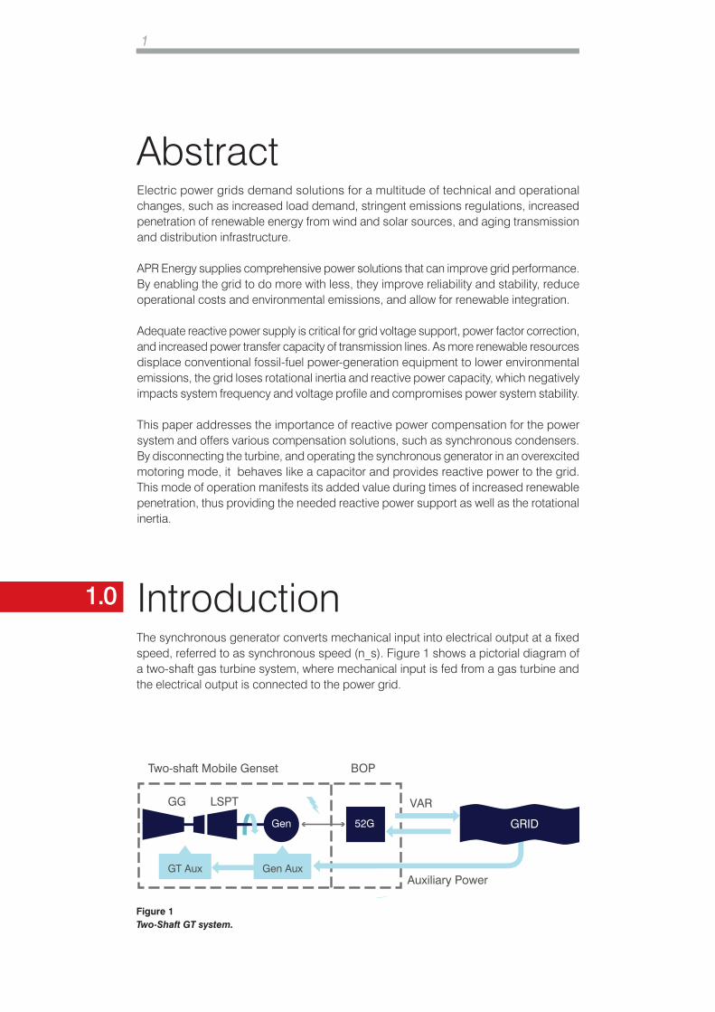
The synchronous generator converts mechanical input into electrical output at a fixed speed, referred to as synchronous speed (n_s). Figure 1 shows a pictorial diagram of a two-shaft gas turbine system, where mechanical input is fed from a gas turbine and the electrical output is connected to the power grid.
Two-shaft Mobile Genset
Auxiliary PowerGT Aux Gen Aux
Gen 52G
BOP
VAR
GRID
GG LSPT
Figure 1 Two-Shaft GT system.
2
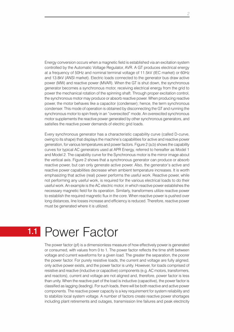
Energy conversion occurs when a magnetic field is established via an excitation system controlled by the Automatic Voltage Regulator, AVR. A GT produces electrical energy at a frequency of 50Hz and nominal terminal voltage of 11.5kV (IEC market) or 60Hz and 13.8kV (ANSI market). Electric loads connected to the generator bus draw active power (MW) and reactive power (MVAR). When the GT is shut down, the synchronous generator becomes a synchronous motor, receiving electrical energy from the grid to power the mechanical rotation of the spinning shaft. Through proper excitation control, the synchronous motor may produce or absorb reactive power. When producing reactive power, the motor behaves like a capacitor (condenser); hence, the term synchronous condenser. This mode of operation is obtained by disconnecting the GT and running the synchronous motor to spin freely in an “overexcited” mode. An overexcited synchronous motor supplements the reactive power generated by other synchronous generators, and satisfies the reactive power demands of electric grid loads.
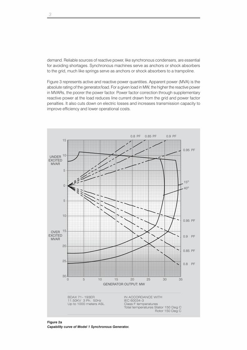
Every synchronous generator has a characteristic capability curve (called D-curve, owing to its shape) that displays the machine’s capabilities for active and reactive power generation, for various temperatures and power factors. Figure 2 (a,b) shows the capability curves for typical AC generators used at APR Energy, referred to hereafter as Model 1 and Model 2. The capability curve for the Synchronous motor is the mirror image about the vertical axis. Figure 2 shows that a synchronous generator can produce or absorb reactive power, but can only generate active power. Also, the generator’s active and reactive power capabilities decrease when ambient temperature increases. It is worth emphasizing that active (real) power performs the useful work. Reactive power, while not performing any useful work, is required for the various electrical loads to do their useful work. An example is the AC electric motor, in which reactive power establishes the necessary magnetic field for its operation. Similarly, transformers utilize reactive power to establish the required magnetic flux in the core. When reactive power is pushed over long distances, line losses increase and efficiency is reduced. Therefore, reactive power must be generated where it is utilized.
1.1 Power FactorThe power factor (pf) is a dimensionless measure of how effectively power is generated or consumed, with values from 0 to 1. The power factor reflects the time shift between voltage and current waveforms for a given load. The greater the separation, the poorer the power factor. For purely resistive loads, the current and voltage are fully aligned, only active power exists, and the power factor is unity. However, for loads comprised of resistive and reactive (inductive or capacitive) components (e.g. AC motors, transformers, and reactors), current and voltage are not aligned and, therefore, power factor is less than unity. When the reactive part of the load is inductive (capacitive), the power factor is classified as lagging (leading). For such loads, there will be both reactive and active power components. The reactive power capacity is a key requirement for system reliability and to stabilize local system voltage. A number of factors create reactive power shortages including plant retirements and outages, transmission line failures and peak electricity
3
demand. Reliable sources of reactive power, like synchronous condensers, are essential for avoiding shortages. Synchronous machines serve as anchors or shock absorbers to the grid, much like springs serve as anchors or shock absorbers to a trampoline.
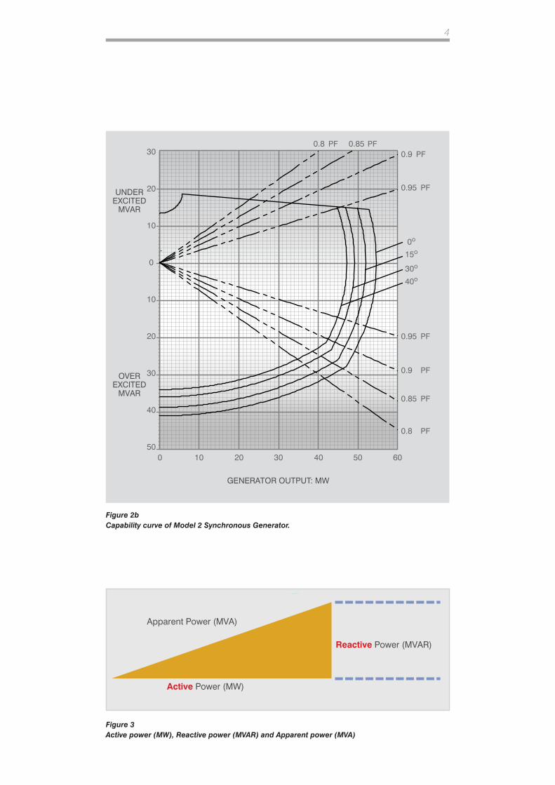
Figure 3 represents active and reactive power quantities. Apparent power (MVA) is the absolute rating of the generator/load. For a given load in MW, the higher the reactive power in MVARs, the poorer the power factor. Power factor correction through supplementary reactive power at the load reduces line current drawn from the grid and power factor penalties. It also cuts down on electric losses and increases transmission capacity to improve efficiency and lower operational costs.
UNDEREXCITED
MVAR
OVEREXCITED
MVAR
BDAX 71- 193ER11.50KV 3 Ph. 50HzUp to 1000 meters ASL
15
10
5
0
5
10
15
20
25
300 5 10 15 20 25 30 35
GENERATOR OUTPUT: MW
0.90.85PF PF PF0.8
0.95
15o
40o
PF
0.95 PF
0.85 PF
0.8 PF
0.9 PF
IN ACCORDANCE WITHIEC 60034-3Class F temperaturesTotal temperatures Stator 150 Deg C
Rotor 150 Deg C
Figure 2a Capability curve of Model 1 Synchronous Generator.
4
Figure 2b Capability curve of Model 2 Synchronous Generator.
Figure 3 Active power (MW), Reactive power (MVAR) and Apparent power (MVA)
UNDEREXCITED
MVAR
OVEREXCITED
MVAR
30
20
10
0
10
20
30
40
500 10 20 30 40 50 60
GENERATOR OUTPUT: MW
0.90.85PF PF
PF0.8
0.95
15o0o
40o
30o
PF
0.95 PF
0.85 PF
0.8 PF
0.9 PF
Active Power (MW)
Reactive Power (MVAR)
Apparent Power (MVA)1.2
6
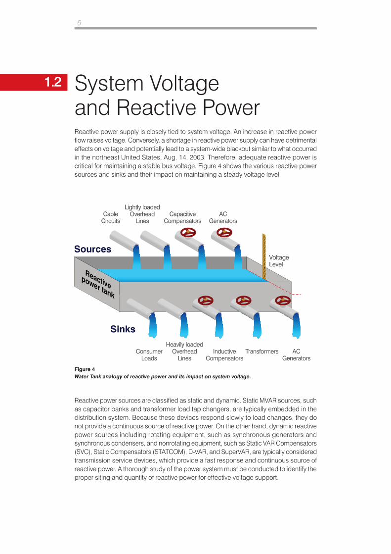
1.2 System Voltage and Reactive PowerReactive power supply is closely tied to system voltage. An increase in reactive power flow raises voltage. Conversely, a shortage in reactive power supply can have detrimental effects on voltage and potentially lead to a system-wide blackout similar to what occurred in the northeast United States, Aug. 14, 2003. Therefore, adequate reactive power is critical for maintaining a stable bus voltage. Figure 4 shows the various reactive power sources and sinks and their impact on maintaining a steady voltage level.
Reactive power sources are classified as static and dynamic. Static MVAR sources, such as capacitor banks and transformer load tap changers, are typically embedded in the distribution system. Because these devices respond slowly to load changes, they do not provide a continuous source of reactive power. On the other hand, dynamic reactive power sources including rotating equipment, such as synchronous generators and synchronous condensers, and nonrotating equipment, such as Static VAR Compensators (SVC), Static Compensators (STATCOM), D-VAR, and SuperVAR, are typically considered transmission service devices, which provide a fast response and continuous source of reactive power. A thorough study of the power system must be conducted to identify the proper siting and quantity of reactive power for effective voltage support.
Sources
Sinks
Lightly loadedOverhead
LinesCapacitive
CompensatorsAC
GeneratorsCable
Circuits
Heavily loadedOverhead
LinesInductive
CompensatorsAC
GeneratorsConsumer
LoadsTransformers
Reactivepower tank
Voltage Level
Figure 4Water Tank analogy of reactive power and its impact on system voltage.
7
1.3
1.4
Capacitor Bank MVARs
Synchronous Machine MVARs
Capacitor banks have been used extensively to provide power factor correction and grid voltage support. These nonrotating machines store electric energy between capacitor plates. In operation, the capacitor bank draws electric current that “leads” the voltage in time and, as such, provides supplementary reactive power needed by electrical loads including induction motors, reactors and transformers. The capacitor bank also supports voltage and contributes to grid stability. However, as a reactive power source, the capacitor bank has shortcomings:
1. Reactive power from the capacitor is proportional to the square of the bus voltage to which the capacitor is connected. Consequently, during a voltage disturbance on the grid, the MVARs produced will experience an even bigger dip (i.e. capacitors are least helpful when they are most needed). This dip is referred to as “low voltage ride through (LVRT)” capability. For example, a voltage dip of 10 percent from nominal voltage would result in a 20 percent MVAR dip.
2. Capacitor bank MVARs are fixed and can, at best, be changed in a pre-defined number of steps.
3. The non-stepless behavior of the capacitor bank results in switching transients.
4. Capacitors are static equipment without rotating mass. They provide no inertia support or LVRT during grid disturbances
MVARs obtained from synchronous machines are dynamic in nature and controlled by the AVR in the excitation system in a stepless manner; hence, no switching transients to produce/absorb MVARs as needed within the capability curve constraints. As a result, the synchronous machine provides better grid voltage support.
Additionally, heavy, rotating synchronous machines store kinetic energy in the rotating shaft to provide critical inertia during grid disturbances. They also increase short-circuit levels at the point-of-connection to the grid; thus, enabling higher penetrations of renewables. Purchased and installed as a stand-alone system on the transmission network, the synchronous condenser provides reactive power and voltage support.
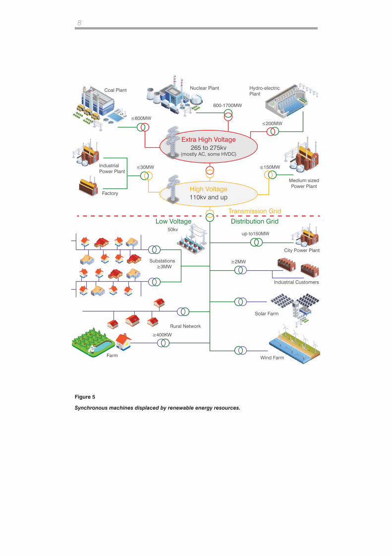
Alternatively, retired coal-fired power plants can be retrofitted to retain synchronous generators (Figure 5) and run as synchronous condensers. The conversion of synchronous generators into synchronous motors makes the most of existing infrastructure, preserves the inertial support of the generator, and provides a dynamic source of reactive power to enhance power system reliability and security and enable high penetrations of renewable energy.
8
Extra High Voltage265 to 275kv
(mostly AC, some HVDC)
High Voltage110kv and up
Coal Plant Nuclear Plant Hydro-electricPlant
Medium sizedPower Plant
City Power Plant
Solar Farm
Rural Network
Wind Farm
Industrial Customers
IndustrialPower Plant
Factory
≤600MW≤200MW
≤30MW
≥2MW
≥400KW
≥3MW
600-1700MW
≤150MW
up to150MW
Transmission Grid
Distribution GridLow Voltage50kv
Substations
Farm
Figure 5
Synchronous machines displaced by renewable energy resources.
9
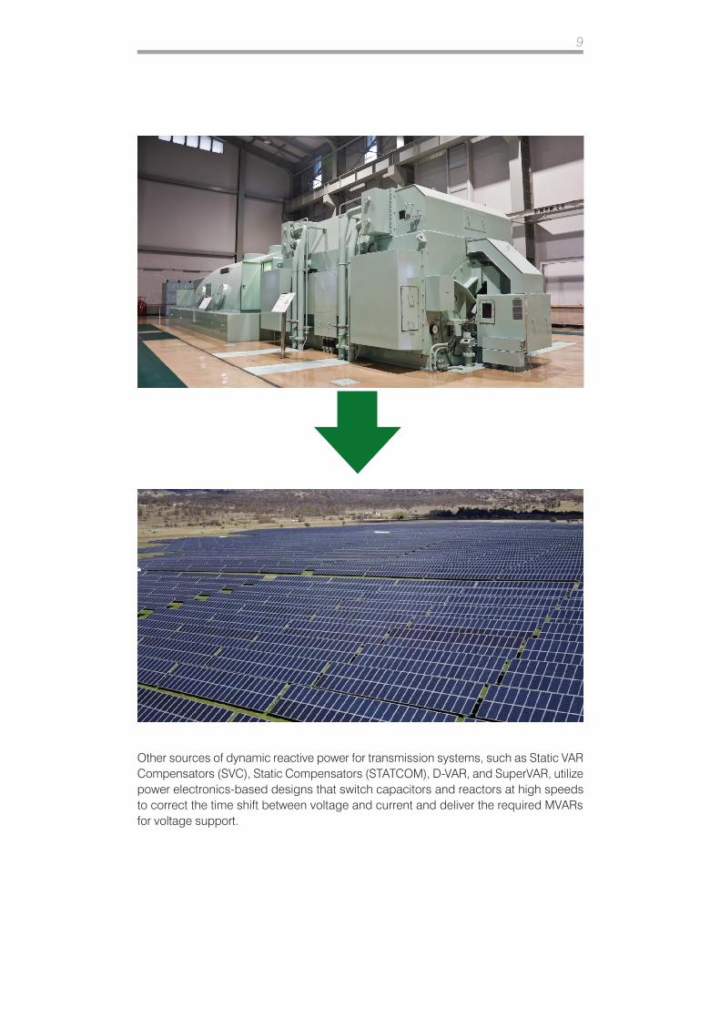
Other sources of dynamic reactive power for transmission systems, such as Static VAR Compensators (SVC), Static Compensators (STATCOM), D-VAR, and SuperVAR, utilize power electronics-based designs that switch capacitors and reactors at high speeds to correct the time shift between voltage and current and deliver the required MVARs for voltage support.
10
1.5
1.6
Operation of Clutchless Turbine Generator Set as Synchronous Condenser In a Clutchless two-shaft system, the gas generator (GG) part is on one shaft and the low-speed turbine (LSPT) driving the synchronous generator is on the other. This design facilitates dual operation of the system. In power generation mode, the GG is fired to produce active and reactive power into the system. Fuel to the GG is shut down when switching from power generation to synchronous condensing mode. At this moment, the synchronous generator starts operating as a synchronous motor, spinning freely at a small parasitic load. However, the motor can produce higher than the rated reactive power into the bus under AVR control. This requires retrofitting of the control software to allow the generator to work in both modes. The ability to produce increased levels of reactive power on demand from the same generator is an added value. Thus, the same generator can provide not only frequency control (power generation mode), but also voltage support (synchronous condensing mode) to facilitate increased renewable penetration. The synchronous condenser is not a generator because there is no turbine driving it, and it is not a motor because there is no mechanical load connected to it. Synchronous Condenser can be considered a “shock absorber” for grid disturbances. These disturbances, if left unattended, can compromise grid stability. As such, synchronous condensing technology serves as an “insurance policy” that is used when needed.
Key Benefits• Synchronous condensers provide dynamic MVARs that boost voltage stability.
• Synchronous condensers Increase the short-circuit level at the point-of-connection to the grid.
• GT-based synchronous condensers can provide MW support to supplement renewable power generation.
• Synchronous condensers do not require changes to the GT or generator core hardware power train, which leverages the reliable design of fleet.
• LSPT and GG are based on low-friction roller and ball bearings to reduce parasitic auxiliary loads.
• No fuel is consumed during synchronous condenser mode as the fuel supply to the GG is shut down.
• Switching between power generation and synchronous condenser modes does not require the generator to be re-synchronized to the grid.
11
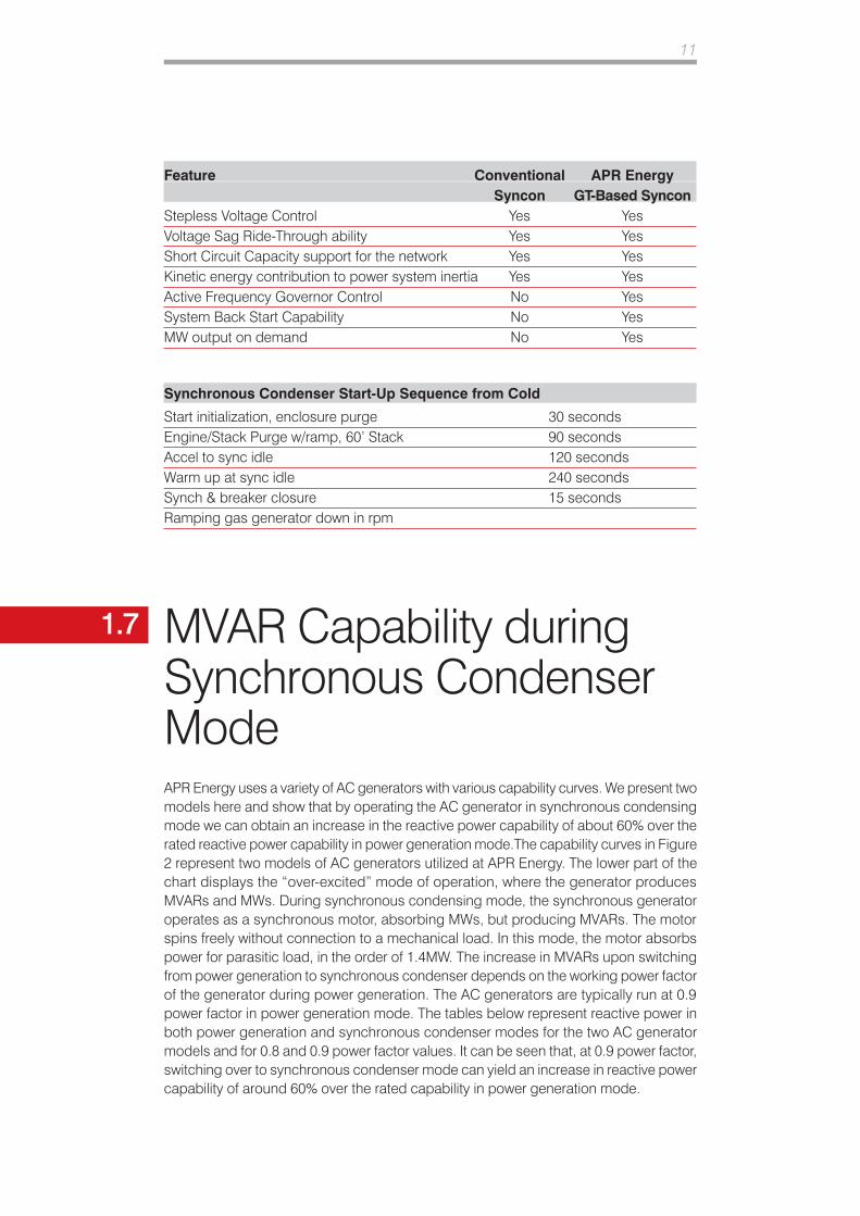
Feature Conventional APR Energy Syncon GT-Based SynconStepless Voltage Control Yes YesVoltage Sag Ride-Through ability Yes YesShort Circuit Capacity support for the network Yes YesKinetic energy contribution to power system inertia Yes YesActive Frequency Governor Control No YesSystem Back Start Capability No YesMW output on demand No Yes
Synchronous Condenser Start-Up Sequence from Cold
Start initialization, enclosure purge 30 secondsEngine/Stack Purge w/ramp, 60’ Stack 90 secondsAccel to sync idle 120 secondsWarm up at sync idle 240 secondsSynch & breaker closure 15 secondsRamping gas generator down in rpm
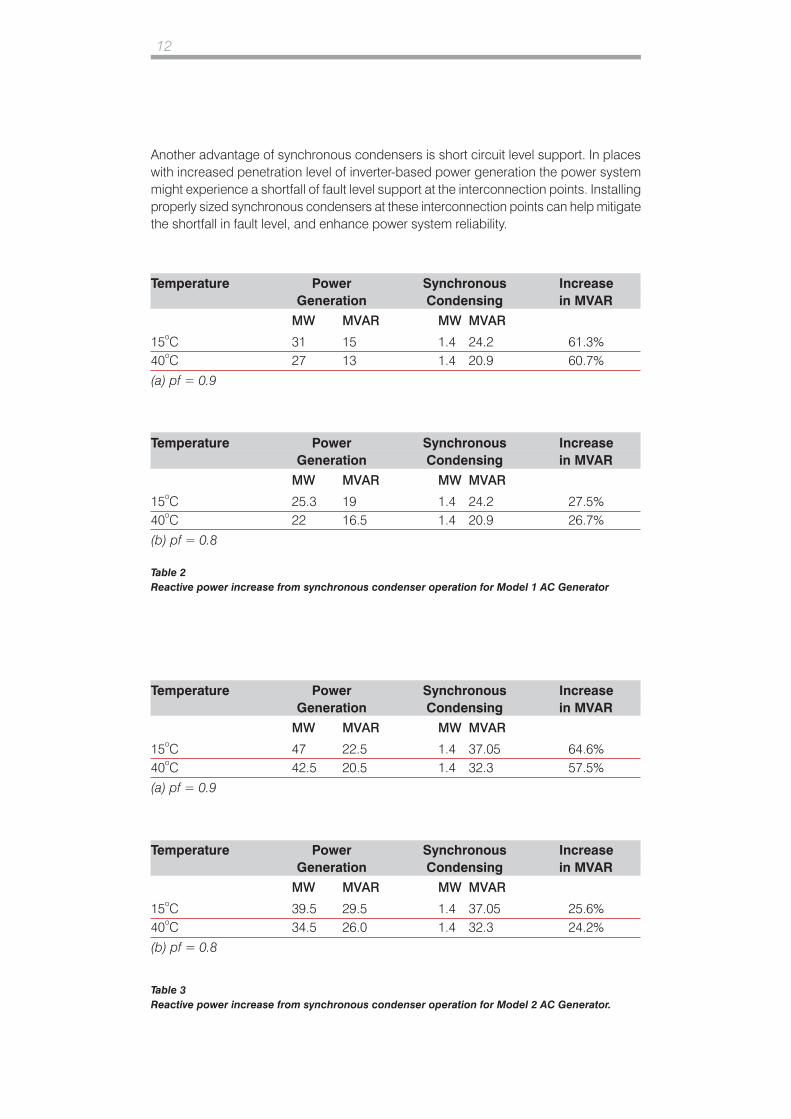
1.7 MVAR Capability during Synchronous Condenser ModeAPR Energy uses a variety of AC generators with various capability curves. We present two models here and show that by operating the AC generator in synchronous condensing mode we can obtain an increase in the reactive power capability of about 60% over the rated reactive power capability in power generation mode.The capability curves in Figure 2 represent two models of AC generators utilized at APR Energy. The lower part of the chart displays the “over-excited” mode of operation, where the generator produces MVARs and MWs. During synchronous condensing mode, the synchronous generator operates as a synchronous motor, absorbing MWs, but producing MVARs. The motor spins freely without connection to a mechanical load. In this mode, the motor absorbs power for parasitic load, in the order of 1.4MW. The increase in MVARs upon switching from power generation to synchronous condenser depends on the working power factor of the generator during power generation. The AC generators are typically run at 0.9 power factor in power generation mode. The tables below represent reactive power in both power generation and synchronous condenser modes for the two AC generator models and for 0.8 and 0.9 power factor values. It can be seen that, at 0.9 power factor, switching over to synchronous condenser mode can yield an increase in reactive power capability of around 60% over the rated capability in power generation mode.
12
Temperature Power Synchronous Increase Generation Condensing in MVAR
MW MVAR MW MVAR
15oC 31 15 1.4 24.2 61.3%40oC 27 13 1.4 20.9 60.7%
(a) pf = 0.9
Temperature Power Synchronous Increase Generation Condensing in MVAR
MW MVAR MW MVAR
15oC 25.3 19 1.4 24.2 27.5%40oC 22 16.5 1.4 20.9 26.7%
(b) pf = 0.8
Temperature Power Synchronous Increase Generation Condensing in MVAR
MW MVAR MW MVAR
15oC 47 22.5 1.4 37.05 64.6%40oC 42.5 20.5 1.4 32.3 57.5%
(a) pf = 0.9
Temperature Power Synchronous Increase Generation Condensing in MVAR
MW MVAR MW MVAR
15oC 39.5 29.5 1.4 37.05 25.6%40oC 34.5 26.0 1.4 32.3 24.2%
(b) pf = 0.8
Table 2Reactive power increase from synchronous condenser operation for Model 1 AC Generator
Table 3Reactive power increase from synchronous condenser operation for Model 2 AC Generator.
Another advantage of synchronous condensers is short circuit level support. In places with increased penetration level of inverter-based power generation the power system might experience a shortfall of fault level support at the interconnection points. Installing properly sized synchronous condensers at these interconnection points can help mitigate the shortfall in fault level, and enhance power system reliability.
13
References:1. Fogarty, J.; and LeClair, R.; “Converting Existing Synchronous Generators into Synchronous Condensers”;
Power Engineering, Issue 10, Vol. 115, 2019.2. “Synchronous Condensers Finding a New Purpose,” Modern Power Systems, April 2019; www.
modernpowersystems.com.3. Igbinovia, F.; Fandi, G; Ahmad, I.; Muller, Z.; and Tlusty, J.; “Modeling and Simulation of the Anticipated Effects
of the Synchronous Condenser on an Electric Power Network with Participating Wind Plants”; Sustainability 2018; 10; 4834; doi:10.3390/su10124834.
4. Hendry, M.; “Using Generators as Synchronous Condensers for Reactive Power & Aero-Derivative Gas Turbine Generators for Spinning Reserve”; Southern California Energy Reliability; Docket No. 12-AFC-02C, May 5, 2018.
5. Dixon, J.; Moran, L.; Rodrigues, J.; and Domke, R. “Reactive Power Compensation Technologies: State-of-the-Art Review”; Proceedings of IEEE; Vol. 93, No. 12, December 2005.
6. “Breaking the Gridlock and Averting Blackouts”; American Superconductor presentation; Massachusetts Restructuring Roundtable, Boston; Sept. 19, 2003.
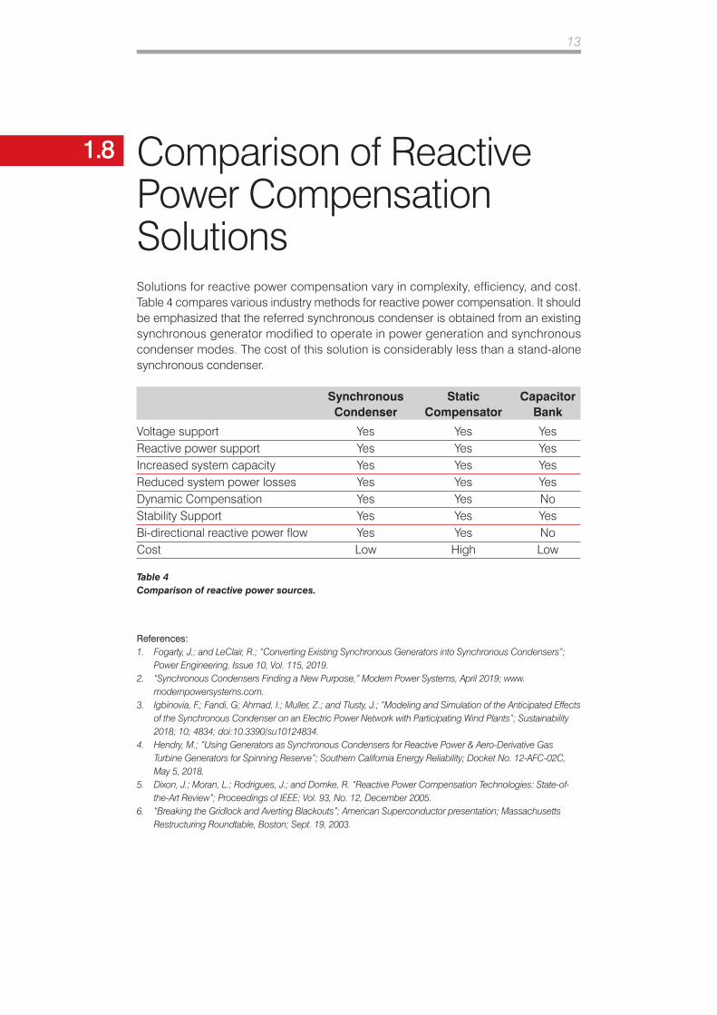
Comparison of Reactive Power Compensation SolutionsSolutions for reactive power compensation vary in complexity, efficiency, and cost. Table 4 compares various industry methods for reactive power compensation. It should be emphasized that the referred synchronous condenser is obtained from an existing synchronous generator modified to operate in power generation and synchronous condenser modes. The cost of this solution is considerably less than a stand-alone synchronous condenser.
Synchronous Static Capacitor Condenser Compensator Bank
Voltage support Yes Yes YesReactive power support Yes Yes YesIncreased system capacity Yes Yes YesReduced system power losses Yes Yes YesDynamic Compensation Yes Yes NoStability Support Yes Yes YesBi-directional reactive power flow Yes Yes NoCost Low High Low
Table 4Comparison of reactive power sources.
1.8
Related Documents