Short Primary Linear Drive with Induction or Synchronous Operation applied in Automated Material Handling Applications Tobias Rafael Fernandes Neto 12 , Ricardo Silva Thé Pontes 1 1 Ceará Federal University - Department of Electrical Engineering 2 Darmstadt University of Technology - Department of Power Electronics and Control of Drives Abstract An industrial manufacturing system, which uses a short primary linear drive, where several vehicles can travel with high speed, high degree of independency and high precision is proposed in this paper. Solutions with short primary and long primary are compared. Short primary linear drives on passive track are advantageous in material handling applications, where moderate dynamic, very long track and closed paths are required. The short primary type uses a passive track and an active vehicle which is supplied by a contactless power transmission system. In order to reduce the costs, a combined operation of permanent magnet linear synchronous motor (PMLSM) and linear induction motor (LIM) is applied to operate the primary as vehicle, avoiding adjustment or releasing of the material during the drive cycle. A theoretical and experimental study was conducted to assess the feasibility of employing the short primary linear motor for a flexible manufacturing system, in which a contactless power transmission provides the basic power and an ultracapacitor storage system provides the peak power. An experimental setup composed by software and hardware, was implemented to perform a smooth transition between the different sections of the track (processing section and transporting section). 1. Introduction Nowadays, the control of electrical machines has an increasing progress, due to the evolution of the power electronics components and the information processing devices, improving the efficiency and safety of industrial systems through the adjustment of the speed, thrust and braking control. The linear electric motors have found their niche and they are now becoming widely used in industrial applications. The linear motors perform better than rotary motor system when the linear motion is required. So far rotary electrical motors with a complex mechanical system of gears, belts, and pulley and screw systems are often used to convert the rotary motion into linear motion. However, this increases the size of the system and reduces the overall system efficiency. Thereby, the use of a linear motor allows to improve the characteristics of an industrial system involving a linear movement of the load, like e.g. low operational and maintenance costs, high efficiency, no backlash, high production throughput and no extra mechanical coupling elements [1][2][3]. Therefore, for each type of rotary electrical machine such as: synchronous, induction, reluctance and direct current (DC), there is a linear equivalent. The high demands on automated handling applications, which require flexible machines, short machine cycle times, high dynamic and linear movement are increasing steadily. In face of that, the linear motors are a suitable solution to these demands, since the linear motion and thrust force generation is direct, not requiring any mechanical transmission component subject to elasticity and wear. Thereby, they are found nowadays in many material handling markets, such as sealed environments for production of solar cells, LCD glass transportation, wood processing, loading gantry systems, packaging systems, machine tools, container transport, pharmaceutical production and food and beverage processing/filling. This paper deals with the short primary linear drive designed for synchronous and induction operation in different sections applied in automated material handling applications. This opens new ideas to

Welcome message from author
This document is posted to help you gain knowledge. Please leave a comment to let me know what you think about it! Share it to your friends and learn new things together.
Transcript
Short Primary Linear Drive with Induction or Synchronous Operation applied in Automated Material Handling Applications
Tobias Rafael Fernandes Neto12, Ricardo Silva Thé Pontes1
1Ceará Federal University - Department of Electrical Engineering
2Darmstadt University of Technology - Department of Power Electronics and Control of Drives
Abstract
An industrial manufacturing system, which uses a short primary linear drive, where several vehicles can travel with high speed, high degree of independency and high precision is proposed in this paper. Solutions with short primary and long primary are compared. Short primary linear drives on passive track are advantageous in material handling applications, where moderate dynamic, very long track and closed paths are required. The short primary type uses a passive track and an active vehicle which is supplied by a contactless power transmission system. In order to reduce the costs, a combined operation of permanent magnet linear synchronous motor (PMLSM) and linear induction motor (LIM) is applied to operate the primary as vehicle, avoiding adjustment or releasing of the material during the drive cycle. A theoretical and experimental study was conducted to assess the feasibility of employing the short primary linear motor for a flexible manufacturing system, in which a contactless power transmission provides the basic power and an ultracapacitor storage system provides the peak power. An experimental setup composed by software and hardware, was implemented to perform a smooth transition between the different sections of the track (processing section and transporting section).
1. Introduction
Nowadays, the control of electrical machines has an increasing progress, due to the evolution of the power electronics components and the information processing devices, improving the efficiency and safety of industrial systems through the adjustment of the speed, thrust and braking control. The linear electric motors have found their niche and they are now becoming widely used in industrial applications. The linear motors perform better than rotary motor system when the linear motion is required. So far rotary electrical motors with a complex mechanical system of gears, belts, and pulley and screw systems are often used to convert the rotary motion into linear motion. However, this increases the size of the system and reduces the overall system efficiency. Thereby, the use of a linear motor allows to improve the characteristics of an industrial system involving a linear movement of the load, like e.g. low operational and maintenance costs, high efficiency, no backlash, high production throughput and no extra mechanical coupling elements [1][2][3]. Therefore, for each type of rotary electrical machine such as: synchronous, induction, reluctance and direct current (DC), there is a linear equivalent.
The high demands on automated handling applications, which require flexible machines, short machine cycle times, high dynamic and linear movement are increasing steadily. In face of that, the linear motors are a suitable solution to these demands, since the linear motion and thrust force generation is direct, not requiring any mechanical transmission component subject to elasticity and wear. Thereby, they are found nowadays in many material handling markets, such as sealed environments for production of solar cells, LCD glass transportation, wood processing, loading gantry systems, packaging systems, machine tools, container transport, pharmaceutical production and food and beverage processing/filling.
This paper deals with the short primary linear drive designed for synchronous and induction operation in different sections applied in automated material handling applications. This opens new ideas to
2
investigate the current systems, simplifying the mechanical complexity and increasing the scalability and independency of the vehicles.
2. Automated Handling Applications
In applications like automated material handling systems, there are typically two different sections: 1.) sections where the work piece should only be transported and 2.) sections where the work piece is sequentially processed with high accuracy. Conventionally, the work piece is fastened within the processing station and released after the processing. As a result, the manufacturing time is significantly increased.
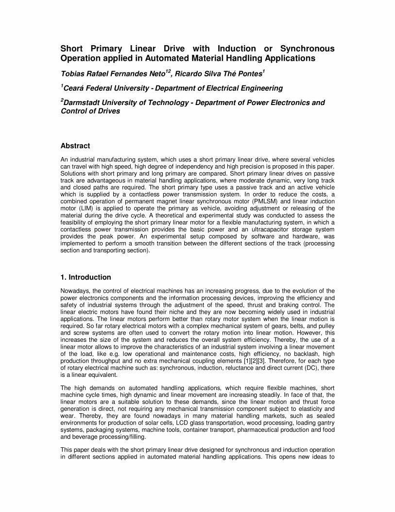
Figure 1 shows a simple example of combined transportation and processing of work pieces with a linear drive system. There, two sections can be distinguished. The first section is the processing station (P1…P4), where high thrust force and high precision are demanded, and the second section is the transporting zone where the vehicle moves forward with lower acceleration. In such flexible chain process with linear drives, the work piece is adjusted at the beginning of the process and released only at the end; that means there is no fastening or releasing of the work piece from the vehicle. Many benefits are achieved by having linear drives, such as: reduced manufacturing time, high dynamic, high precision (few µm), high productivity and reduced maintenance cost [3].
Figure 1. Combined material transfer and processing line system with a short primary linear drive.
Combined transportation and processing of work pieces using linear drive systems, as depicted in Figure 1, requires the following properties:
• On the guide-way (track) several vehicles must travel with a high degree of independency (all the vehicles can start and brake without dynamic restriction).
• Each vehicle has to be controlled very precisely by using a position sensor, when the vehicle operates within the processing section. Unlike the processing section, the sensorless motion control or one sensor with less accuracy may be used within the transporting section, in order to reduce the costs.
• The guide-way must allow for horizontal and vertical curves and for closed paths.
Regarding to the features of the automated material handling application, like: number of vehicles, track length, maximum speed and acceleration, sealed environment (vacuum), scalability and cost, the suitable linear drive topology (e.g. short or long primary) may be discussed. Therefore, the long and short primary topologies used to fulfill the system depicted in Figure 1 are presented and discussed in the following subsection.
3
2.1 Long Primary topology
For the long primary configuration, the primary remains static as a track and the secondary is the work piece carrier. Hence, we have an active track (primary) with passive and lightweight vehicles (secondary), avoiding brushes and cables to transfer energy and information to the moving part and with the possibility to reach a high dynamic. In applications with very long active tracks, the primaries are arranged in several electrical independent segments, in order to reduce the reactive power of the dedicated inverter and save energy (only the segments where the vehicle is located are switched on, all the other are turned off) [3]. Furthermore, in short active track applications with multiples carries, the active track is also divided in many segments, since the desired number of vehicles depends on the size of the long primary (for individual vehicle motion control). The lowest possible number of segments per vehicle are two, considering that two segments are activated during the transition [4].
The position measurement is made by installing a scale at the passive vehicle and a stationary position sensor only within the processing station, so that, depending on the length to be acquired, the control system to be implemented is very complex (segmented position sensors) [5]. Under the application condition, that the vehicle must have a high dynamic inside the processing station, the flat single-sided PMLSM provides a good and feasible solution. Therefore, the moving secondary is a plate with a permanent magnet array. In single-sided PMLSM, the attractive force between the primary and secondary is very high, being necessary a robust mechanical structure. However, the double-sided topology can be used to fulfill the high acceleration requirement, without the strengthening of the mechanical structure.
For automated material handling application with long primary topology, there are two alternatives to supply each primary segment. The first option is multiplexing of inverters, which feed the primaries, by mechanical or electronic switches [3]. Such concept can reduce the number of inverters (two inverters per vehicle), but it seems not to be a good option, since the complexity and cost rise together with the track size [3][4]. The second alternative is to feed each primary segment with a dedicated inverter, so that a large number of primary segments imply a large number of inverters. The physical distribution of the components for the second alternative produces another two possibilities. They are listed below:
• Long primary topology with centralized controllers: The inverters and controllers are accommodated together in a cabinet with all auxiliary components, and each inverter feeds one primary segment. Furthermore, each vehicle has its own vehicle controller. Then, all segments are connected by shielded motor cables [5].
• Long primary topology with distributed controllers: the inverters and controllers can be placed near each segment along the track with a common DC-link, reducing the cable installation costs [6]. Moreover, each primary segment has one vehicle controller.
2.1.1 Long primary topology with centralized controllers
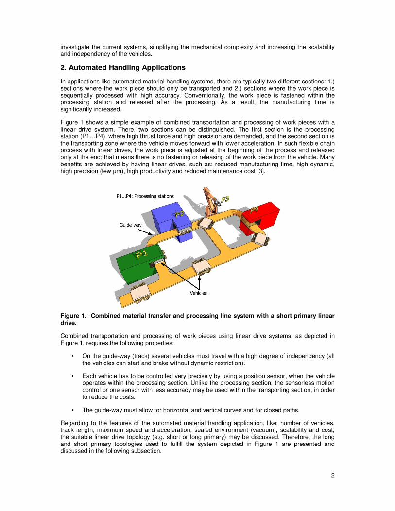
According to the previous subsection, the long primary topology with centralized controllers has one vehicle controller (VC) assigned to each vehicle, as depicted in Figure 2. The VC receives feedback data (current, speed and position) from the active inverter which feeds the respective segment. Then, the received data are processed by the VC control algorithm, and the switching time information is transmitted back to the inverter through an inverter-bus. The inverter-bus provides communication between each VC and each inverter inside one control cycle [4]. All inverters are connected at the same DC-link, and they are installed with the VCs within a cabinet, as illustrated in Figure 2. The motion controller (MC) is composed by industrial PC or PLCs which control the actual position of the vehicle.
For such topology, one control cycle should be splitted in some intervals, which are equivalent to each controlled vehicle [4]. In one vehicle interval, two primary segments can be activated and controlled simultaneously. Since a good dynamic is demanded for such application, the number of travelling vehicles is limited, due to the reduction of these time intervals, which requires an increasing of the bandwidth. [3][4]. Such inverter-bus bandwidth limitation is the bottleneck point to increase the scale of the system. Figure 2 shows that the motor cable connection (cabinet motor) could increase the overall costs for large applications with several segments. Altogether, the given topology is
4
recommended for automated material handling system with low traffic density (low number of vehicle per track length).
1
Processing
station
Sensor
Linear scale
Primary
segment
SecondaryCabinet
VC
MC
Inverter-BusVC=Vehicle
controller
MC=Motion
controller
DC-link
Primary n. 2 3 4 5 6
1
23
4
5
6
OFF
ON
3
2
1
1 VC 2 VC 3
Figure 2. Long primary topology with centralized controllers.
2.1.2. Long primary topology with distributed controllers
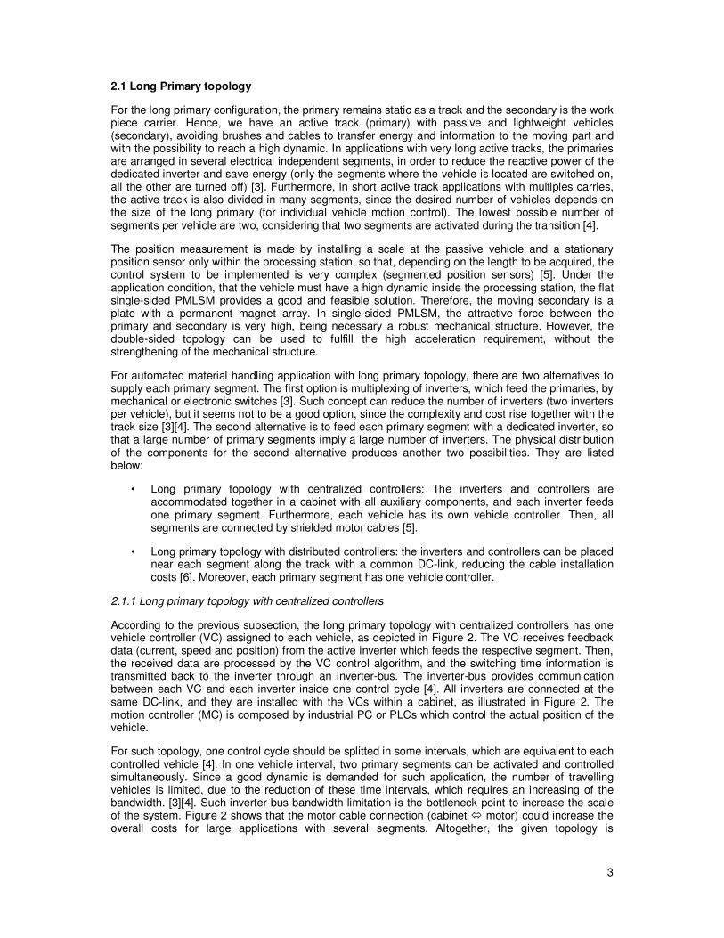
For industrial automated material handling application which requires a high traffic density, the long primary topology with distributed controllers is a suitable solution. The inverter-bus bandwidth limitation for centralized controllers is settled by placing the VC and inverter inside a module. Therefore, the module is responsible to supply the primary segment. Figure 3 shows a system with three passive vehicles, six segments and six modules. The travelling vehicle is commanded directly by the module, since one VC is attributed to one inverter, as shown in Figure 3. In case of the vehicle be moving between two segments, the data (speed, position and current) are transmitted synchronously to the adjacent VC (inside the next module) using a high speed point-to-point communication [6].
Figure 3. Long primary topology with distributed controllers.
5
Moreover, the motion controller is connected to each module by a physical industrial field bus interface [6]. The MC generates the reference position and receives the actual position from all vehicles. Such a topology has a high degree of scalability, and future expansions can be easily implemented increasing the number of modules and primary segments. On the other hand, the implementation costs rise with the number of the segments and modules for a very large system.
2.2 Short Primary topology
The short primary topology uses the three-phase winding mounted on the moving part (active vehicle) to produce the travelling magnetic field, and the secondary is the passive part, which is utilized as guide-way. The energy has to be transmitted to the vehicle, since the primary part must be supplied. Exact commutation of motor current, speed control and positioning require a linear measuring sensor which is typically attached to the active vehicle. Generally, in industrial application with very short track (e.g. machine tools), the power supply and the actual position are transferred and acquired from the moving primary by using a drag-chain or sliding contacts. The same drag-chain is also used to place the cables, which are used to read the actual position information. The inverter and controllers are located in a stationary cabinet near to the vehicle. The utilization of a drag-chain is improper for the system presented in Figure 1, where the vehicles should move along a track with closed paths and sharp curves. Considering an automated material handling application with linear drives that is characterized by a very long track, low density of vehicles and moderate dynamic, the short primary topology affords a very simple track construction, allowing also sharp horizontal and vertical curves and causing lower implementation cost for the track than the long primary topology presented in the previous subsections. The limitations of the short primary topology are given mainly by the power supply system (energy must be transferred to the moving windings) and the significantly reduced dynamic (acceleration), due to a heavier vehicle than with the long primary topology. On the other hand, the system is more flexible in case of vehicle failure, since it can be easily removed, and the system can continue the work normally.
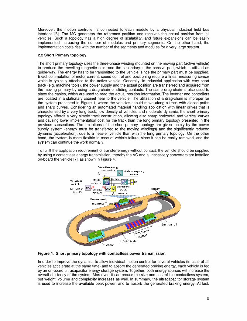
To fulfill the application requirement of transfer energy without contact, the vehicle should be supplied by using a contactless energy transmission, thereby the VC and all necessary converters are installed on-board the vehicle [7], as shown in Figure 4.
Figure 4. Short primary topology with contactless power transmission.
In order to improve the dynamic, to allow individual motion control for several vehicles (in case of all vehicles accelerate at the same time) and to absorb the generated braking energy, each vehicle is fed by an on-board ultracapacitor energy storage system. Together, both energy sources will increase the overall efficiency of the system. Moreover, it can reduce the size and cost of the contactless system, but weight, volume and complexity increases as well. In summary, the ultracapacitor storage system is used to increase the available peak power, and to absorb the generated braking energy. At last,
6
just one contactless energy system is responsible to supply energy to all vehicles, as depicted in Figure 4.
This short primary topology has some advantages in comparison with the long primary topology, such as:
• The number of inverters and VS units is equal to the number of vehicles plus a stationary medium frequency inverter. Therefore, the number of vehicles is not limited as with the long primary topology (two primary segments for one vehicle).
• Reduced reactive power in the on-board inverter.
• The short primary has a better efficiency.
• The position sensor is attached to the active vehicle, thus one sensor per vehicle is necessary, and the acquired actual position is processed on-board of the active vehicle, making it simpler than the long primary topology.
The central MC produces the reference position to coordinate all active vehicles, and get the actual position data transmitted by the VC. To fulfill this communication demand, a wireless network should be utilized, since no contact is demanded. Figure 4 outlines two sections. The first section is a station where the work pieces are processed. While processing, high thrust force and precision are necessary. The second section is outside the processing station. There, a lower thrust force is sufficient to keep the active vehicle moving with a low acceleration towards the next processing station. As a result, the passive track will consist of two different section types: high thrust force sections using stationary permanent magnets and low thrust force sections using an induction rail. The induction rail is composed of two layers: copper and back iron. Surely, the cost of the track can be reduced by saving the stationary permanent magnets outside the processing station.
3. Experimental setup and results
3.1 Construction and Specification of the Experimental Setup
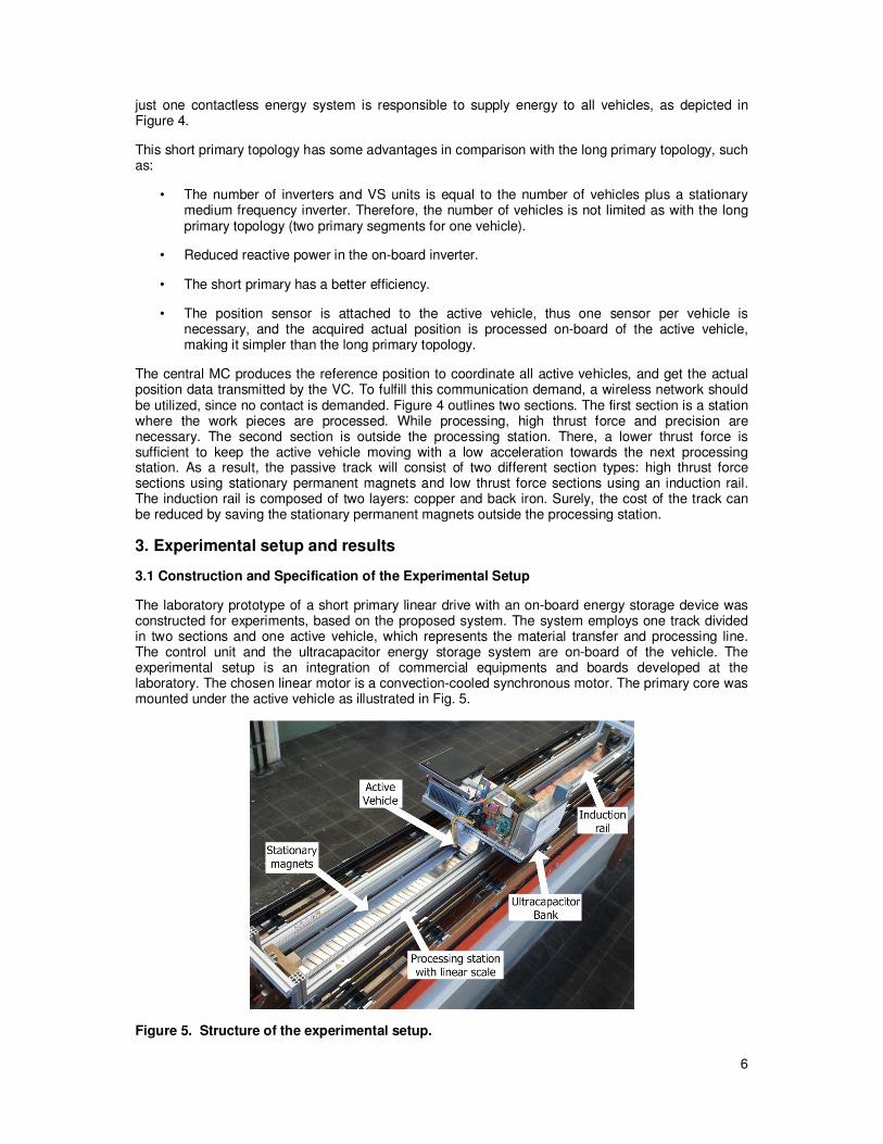
The laboratory prototype of a short primary linear drive with an on-board energy storage device was constructed for experiments, based on the proposed system. The system employs one track divided in two sections and one active vehicle, which represents the material transfer and processing line. The control unit and the ultracapacitor energy storage system are on-board of the vehicle. The experimental setup is an integration of commercial equipments and boards developed at the laboratory. The chosen linear motor is a convection-cooled synchronous motor. The primary core was mounted under the active vehicle as illustrated in Fig. 5.
Figure 5. Structure of the experimental setup.
7
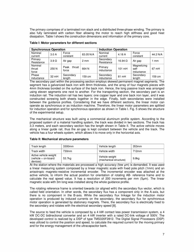
The primary comprises of a laminated iron stack and a distributed three-phase winding. The primary is also fully laminated with carbon fiber allowing the motor to reach high stiffness and good heat dissipation. Table I shows the construction dimensions and information of the primary core.
Table I: Motor parameters for different sections
Synchronous Operation Induction Operation Nominal current
3.0 A Force constant
83.05 N/A Nominal current
4.18 A Force constant
44.2 N/A
Primary Resistance
3.9 Ω Air gap 2 mm Secondary Resistance
16.94 Ω Air gap 1 mm
Nominal thrust force
250 N Peak thrust force
664 N Primary inductance
101 mH Magnetizing self-inductance
67 mH
Phase inductance
32 mH Secondary length
159 cm Secondary inductance
81 mH Secondary length
159 cm
The secondary part within the processing section employs skewed permanent magnet segments. The segment has a galvanized back iron with 8mm thickness, and the array of four magnets pieces with 4mm thickness bonded on the surface of the back iron. Hence, the long passive track was arranged using eleven segments one next to another. For the transporting section, the secondary part is an induction rail. The induction rail has two layers: one copper layer and one back iron layer, and it was constructed screwing both sheets together in the edge. Finally, both secondaries were installed between the guidance profiles. Considering that we have different sections, the linear motor can operate as synchronous or as induction machine. Therefore, the linear motor parameters are splitted for induction operation and for synchronous operation as shown in Table I. Fig. 5 shows the structure of the experimental setup.
The mechanical structure was built using a commercial aluminum profile system. According to the proposed system of a material handling system, the track was divided in two sections. The track has 3.3 meters, and each secondary section has the length shown in Table II. The active vehicle moves along a linear guide rail, thus the air-gap is kept constant between the vehicle and the track. The vehicle has a four wheels system, which allows it to move only in the horizontal axis.
Table II: Mechanical structure parameters
Track length 3300mm Vehicle length 353mm
Track width 730mm Vehicle width 712mm
Active vehicle weight (vehicle + on-board devices)
53.7kg Vehicle weight (mechanical structure)
9.8kg
At the station where the materials are processed a high accuracy (few µm) is demanded. It was used a linear measuring system composed by a linear magnetic scale with fixed pole pitch (1mm) and an anisotropic magneto-resistive incremental encoder. The incremental encoder was attached at the active vehicle, to inform the actual position for orientation of rotating AB- reference frame and to calculate the real speed value. It has a resolution of 200 increments per mm (5µm). The linear magnetic scale with 3m long was installed along the whole guidance profile.
The rotating reference frame is oriented towards (or aligned with) the secondary flux vector, which is called field orientation. In other words, the secondary flux has a component only in the A-axis, but there is no component in the B-axis. While the secondary flux linkage for the induction motor operation is produced by induced currents on the secondary, the secondary flux for synchronous motor operation is generated by stationary magnets. There, the secondary flux is electrically fixed to the secondary and rotates with the electrical secondary speed [8].
The source to feed the vehicle is composed by a 4 kW contact less power transmission system, a 4 kW DC-DC bidirectional converter and an 4 kW inverter with a rated DC-link voltage of 500V. The developed control is realized by a DSP of type TMS320F2812. The Digital Signal Processors (DSP) was utilized to control the position and speed, to calculate the required current for the moving primary and for the energy management of the ultracapacitor bank.

8
3.2 Experimental Results
The incremental encoder measures the position. The speed is obtained by numerical derivation and filtering. This filter may hide transients in real speed and of course in acceleration (force). Additionally, the very high mass (53.7 kg) of the vehicle prevents that transients in force can be easily concluded from the recorded speed. In order to test the position performance of the proposed control strategy, a position command (x*=2.8m) was sent to the vehicle. The vehicle starts from the initial position (x=0m) on the processing station at time t0, and reaches the transition area at the time t1. Afterwards, the optimum position γ is achieved at time t2, and at time t3 the vehicle covers only the induction rail.
The optimum position γ was determined experimentally such that a sufficient thrust force with acceptable disturbance is reached. In other words, if the operation mode is changed too late from PMLSM Field Oriented Control (FOC) to LIM-FOC, the thrust force required to guarantee a constant speed will not be achieved in the transition area.
For the synchronous operation, it is utilized only the B-axis current component i1B, whereas in induction operation mode, both current components (i1A and i1B) are injected. During the transition moment, the majority of the thrust force should be generated with the primary working in synchronous operation mode due to the fact that the induction operation requires more power and causes more power losses to keep the thrust force at the same level. Definitely, the LIM-FOC operation should be
activated as late as possible. In face of that, the position value γ was fixed taking such that the speed variation of the active vehicle was small. Based on the criteria above, several experimental tests were carried out, and it was determined that the operation mode should be changed when the vehicle has
64% of its length above the induction rail, then the optimum position value is γ=209mm.
At time t4, the vehicle receives the new reference position (x*=0m) and finally returns to the original position, as illustrated in Figure 6.
Figure 6. Sketch of the active vehicle position during the experimental drive cycle.
For this experimental test, the speed was limited to 1m/s, the current i1B was limited to 8A and the magnetizing current was set to i1A=3.6A. During the drive, the active vehicle crosses both secondaries and returns to the original position.
The experimental test was carried out in order to simulate a supposed situation where the vehicle leaves a processing station, but it needs to wait for the next processing station to be released. Then, it should stop for few seconds and move again toward the next processing station. At the border between both secondaries, there are some disturbances in the vehicle's speed that must be compensated by the current controller. The speed, position and current responses for the executed experimental test are shown in Figure 7. Also, Figure 7 shows that LIM FOC starts with the
magnetizing current i1A being injected by the current controller (∆t=t6-t2).

9
Figure 7. Measured position, speed and current for the drive cycle.
4. Conclusions
Considering automated material handling applications, the use of short primary linear drives are proposed. Solutions with short primary and long primary were compared. For the long primary linear drive, different topologies concerning power- and information- processing were compared. Concerning costs reduction, sections where the work pieces are transported, the final cost of the application is reduced by saving magnets. The short primary linear drive was implemented, which allows that horizontal and vertical curves be easily built due to the simple secondary part (reaction rail or stationary magnets). The track was equipped with a linear magnetic scale inside and outside the processing station, for high accuracy of positioning. As the linear scale was installed in the whole track, all the traveling vehicles can be stopped inside the transporting section and wait the next processing station be released. Therefore, in automated material handling applications with very long track, low density of vehicles and moderate acceleration, short primary linear machines are a good solution. The developed transition control strategy was implemented to control the active vehicle for a lower speed drop, a sufficient thrust force, optimal dynamic performance and low power consumption, when it moves between the permanent magnets and the reaction rail sections.
References
[1] Gieras J. Linear Induction Drives. Oxford: Clarendon Press, 1994, ISBN 0198593813.
[2] Laithwaite E. R. Linear electric machines – a personal view, in Proceedings of the IEEE, vol. 63, no. 2, pp. 250-290, February. 1975.
[3] Brandenburg G., Brückl S., Dormann J., Heinzl J., and Schmidt C. Comparative investigation of rotary and linear motor feed drive systems for high precision machine tools, in 6th International workshop on Advanced Motion Control, Mar-Apr. 30-1, 2000, pp. 384-389.

10
[3] Mutschler P. and Silaghiu S. Linear drives for material handling and processing: A comparison of system architectures, in 34th Annual Conference of the IEEE Industrial Electronics Society, 2008, IECON ‘08, pp. 1264-1269.
[4] Benavides R. Investigation of control methods for segmented long stator linear drives. PhD. thesis, TU Darmstadt, Germany 2008.
[5] Mihalachi M. and Mutschler P. Long primary linear drive for material handling, in International Conference on Electrical Machines and Systems,2009, ICEMS’09, pp. 1-6.
[6] Silaghiu S. and Mutschler P. Optimizing operation of segmented stator linear synchronous motors, in 5th IET International Conference on Power Electronics, Machines and Drives, 2010, PEMD‘10, pp. 1-6.
[7] Fernandes Neto T.R. and Mutschler P. Short primary linear synchronous motor drive with an ultracapacitor regenerative braking system for material handling and processing, in 8
th
International Symposium on Linear Drives for Industry Applications, 2011, LDIA’11.
[8] Fernandes Neto T.R. and Mutschler P. Combined operation of short-primary permanent magnet linear synchronous motor and linear induction motor in material handling applications. in Applied Power Electronics Conference and Exposition, 2012, APEC 2012, pp. 915 - 922.
Related Documents