. FlexiPacket Radio Solution Overview and First Installation Procedures A25000-A1200-A008-02-76P1 Issue: 2 Issue date: January 2010

20 - Solution Overview and First Installation Procedures
Oct 01, 2014
Welcome message from author
This document is posted to help you gain knowledge. Please leave a comment to let me know what you think about it! Share it to your friends and learn new things together.
Transcript
.
FlexiPacket Radio
Solution Overview and First Installation Procedures
A25000-A1200-A008-02-76P1
Issue: 2 Issue date: January 2010
.
.2 A25000-A1200-A008-02-76P1Issue: 2 Issue date: January 2010
Solution Overview and First Installation Procedures
The information in this document is subject to change without notice and describes only the product defined in the introduction of this documentation. This documentation is intended for the use of Nokia Siemens Networks customers only for the purposes of the agreement under which the document is submitted, and no part of it may be used, reproduced, modified or transmitted in any form or means without the prior written permission of Nokia Siemens Networks. The documentation has been prepared to be used by professional and properly trained personnel, and the customer assumes full responsibility when using it. Nokia Siemens Networks welcomes customer comments as part of the process of continuous development and improvement of the documentation.
The information or statements given in this documentation concerning the suitability, capacity, or performance of the mentioned hardware or software products are given "as is" and all liability arising in connection with such hardware or software products shall be defined conclusively and finally in a separate agreement between Nokia Siemens Networks and the customer. However, Nokia Siemens Networks has made all reasonable efforts to ensure that the instructions contained in the document are adequate and free of material errors and omissions. Nokia Siemens Networks will, if deemed necessary by Nokia Siemens Networks, explain issues which may not be covered by the document.
Nokia Siemens Networks will correct errors in this documentation as soon as possible. IN NO EVENT WILL NOKIA SIEMENS NETWORKS BE LIABLE FOR ERRORS IN THIS DOCUMEN-TATION OR FOR ANY DAMAGES, INCLUDING BUT NOT LIMITED TO SPECIAL, DIRECT, INDIRECT, INCIDENTAL OR CONSEQUENTIAL OR ANY LOSSES, SUCH AS BUT NOT LIMITED TO LOSS OF PROFIT, REVENUE, BUSINESS INTERRUPTION, BUSINESS OPPORTUNITY OR DATA,THAT MAY ARISE FROM THE USE OF THIS DOCUMENT OR THE INFORMATION IN IT.
This documentation and the product it describes are considered protected by copyrights and other intellectual property rights according to the applicable laws.
The wave logo is a trademark of Nokia Siemens Networks Oy. Nokia is a registered trademark of Nokia Corporation. Siemens is a registered trademark of Siemens AG.
Other product names mentioned in this document may be trademarks of their respective owners, and they are mentioned for identification purposes only.
Copyright © Nokia Siemens Networks 2010. All rights reserved.
f Important Notice on Product SafetyElevated voltages are inevitably present at specific points in this electrical equipment. Some of the parts may also have elevated operating temperatures.
Non-observance of these conditions and the safety instructions can result in personal injury or in property damage.
Therefore, only trained and qualified personnel may install and maintain the system.
The system complies with the standard EN 60950 / IEC 60950. All equipment connected has to comply with the applicable safety standards.
The same text in German:
Wichtiger Hinweis zur Produktsicherheit
In elektrischen Anlagen stehen zwangsläufig bestimmte Teile der Geräte unter Span-nung. Einige Teile können auch eine hohe Betriebstemperatur aufweisen.
Eine Nichtbeachtung dieser Situation und der Warnungshinweise kann zu Körperverlet-zungen und Sachschäden führen.
Deshalb wird vorausgesetzt, dass nur geschultes und qualifiziertes Personal die Anlagen installiert und wartet.
Das System entspricht den Anforderungen der EN 60950 / IEC 60950. Angeschlossene Geräte müssen die zutreffenden Sicherheitsbestimmungen erfüllen.
.
.
A25000-A1200-A008-02-76P1Issue: 2 Issue date: January 2010
3
Solution Overview and First Installation Procedures
Table of ContentsThis document has 39 pages.
1 Preface . . . . . . . . . . . . . . . . . . . . . . . . . . . . . . . . . . . . . . . . . . . . . . . . . . 71.1 Intended audience . . . . . . . . . . . . . . . . . . . . . . . . . . . . . . . . . . . . . . . . . . 71.2 Structure of this document . . . . . . . . . . . . . . . . . . . . . . . . . . . . . . . . . . . . 71.3 Symbols and conventions . . . . . . . . . . . . . . . . . . . . . . . . . . . . . . . . . . . . 71.4 History of changes . . . . . . . . . . . . . . . . . . . . . . . . . . . . . . . . . . . . . . . . . . 91.5 Waste electrical and electronic equipment (WEEE) . . . . . . . . . . . . . . . . 91.6 RoHS compliance . . . . . . . . . . . . . . . . . . . . . . . . . . . . . . . . . . . . . . . . . . 9
2 FlexiPacket Microwave scenario (FP10) . . . . . . . . . . . . . . . . . . . . . . . . 112.1 Overview . . . . . . . . . . . . . . . . . . . . . . . . . . . . . . . . . . . . . . . . . . . . . . . . 112.2 First installation procedures . . . . . . . . . . . . . . . . . . . . . . . . . . . . . . . . . . 112.2.1 PC requirements . . . . . . . . . . . . . . . . . . . . . . . . . . . . . . . . . . . . . . . . . . 122.2.2 First installation procedure. . . . . . . . . . . . . . . . . . . . . . . . . . . . . . . . . . . 122.3 FlexiPacket Hub configuration . . . . . . . . . . . . . . . . . . . . . . . . . . . . . . . . 212.3.1 Module port enabling . . . . . . . . . . . . . . . . . . . . . . . . . . . . . . . . . . . . . . . 212.3.2 Service creation . . . . . . . . . . . . . . . . . . . . . . . . . . . . . . . . . . . . . . . . . . . 232.3.3 How to create E1 Services. . . . . . . . . . . . . . . . . . . . . . . . . . . . . . . . . . . 242.3.4 How to create E-Line Services. . . . . . . . . . . . . . . . . . . . . . . . . . . . . . . . 252.3.5 How to cross-connect NNI to NNI Services (in a node configuration) . . 28
3 FlexiBTS scenario (RU10) . . . . . . . . . . . . . . . . . . . . . . . . . . . . . . . . . . . 303.1 Overview . . . . . . . . . . . . . . . . . . . . . . . . . . . . . . . . . . . . . . . . . . . . . . . . 303.2 Line-up and commissioning . . . . . . . . . . . . . . . . . . . . . . . . . . . . . . . . . . 31
4 Synchronous Ethernet configuration procedure for FlexiPacket single link solution during first installation and commissioning . . . . . . . . . . . . . . . . 34
4.1 Introduction . . . . . . . . . . . . . . . . . . . . . . . . . . . . . . . . . . . . . . . . . . . . . . 344.2 Equipment setup . . . . . . . . . . . . . . . . . . . . . . . . . . . . . . . . . . . . . . . . . . 344.3 Procedure . . . . . . . . . . . . . . . . . . . . . . . . . . . . . . . . . . . . . . . . . . . . . . . 35
.
.4 A25000-A1200-A008-02-76P1Issue: 2 Issue date: January 2010
Solution Overview and First Installation Procedures
List of FiguresFigure 1 WEEE label. . . . . . . . . . . . . . . . . . . . . . . . . . . . . . . . . . . . . . . . . . . . . . . . 9Figure 2 First Installation Scenario example . . . . . . . . . . . . . . . . . . . . . . . . . . . . . 12Figure 3 Computer connection to the FlexiPacket Hub. . . . . . . . . . . . . . . . . . . . . 13Figure 4 A2200 First Installation application directory files . . . . . . . . . . . . . . . . . . 13Figure 5 Running application . . . . . . . . . . . . . . . . . . . . . . . . . . . . . . . . . . . . . . . . 13Figure 6 Computer connection . . . . . . . . . . . . . . . . . . . . . . . . . . . . . . . . . . . . . . . 14Figure 7 MWP First Installation Wizard. . . . . . . . . . . . . . . . . . . . . . . . . . . . . . . . . 15Figure 8 MWR First Installation Wizard (Welcome screen) . . . . . . . . . . . . . . . . . 15Figure 9 MWR First Installation Wizard (Configuration) . . . . . . . . . . . . . . . . . . . . 16Figure 10 MWR First Installation Wizard (End of configuration) . . . . . . . . . . . . . . . 17Figure 11 Example configuration . . . . . . . . . . . . . . . . . . . . . . . . . . . . . . . . . . . . . . 17Figure 12 MWR Upgrade Wizard directory files . . . . . . . . . . . . . . . . . . . . . . . . . . . 18Figure 13 MWR Upgrade Wizard welcome screen . . . . . . . . . . . . . . . . . . . . . . . . . 19Figure 14 LPG Commissioning window . . . . . . . . . . . . . . . . . . . . . . . . . . . . . . . . . 19Figure 15 LPG example . . . . . . . . . . . . . . . . . . . . . . . . . . . . . . . . . . . . . . . . . . . . . 20Figure 16 FlexiPacket Hub - Main view. . . . . . . . . . . . . . . . . . . . . . . . . . . . . . . . . . 21Figure 17 Equipment Status & Configuration window. . . . . . . . . . . . . . . . . . . . . . . 22Figure 18 Port Management window - Module 1 (8-port Eth Access Module) . . . . 22Figure 19 Port Management window - Module 2 (16-port T1/E1 Access Module) . 23Figure 20 Services Status & Configuration . . . . . . . . . . . . . . . . . . . . . . . . . . . . . . . 23Figure 21 Add CES window . . . . . . . . . . . . . . . . . . . . . . . . . . . . . . . . . . . . . . . . . . 24Figure 22 Service Protection. . . . . . . . . . . . . . . . . . . . . . . . . . . . . . . . . . . . . . . . . . 25Figure 23 Add E-Line Services window . . . . . . . . . . . . . . . . . . . . . . . . . . . . . . . . . 26Figure 24 Service Protection. . . . . . . . . . . . . . . . . . . . . . . . . . . . . . . . . . . . . . . . . . 27Figure 25 Add NNI to NNI window . . . . . . . . . . . . . . . . . . . . . . . . . . . . . . . . . . . . . 28Figure 26 Service Protection. . . . . . . . . . . . . . . . . . . . . . . . . . . . . . . . . . . . . . . . . . 29Figure 27 BTS scenario . . . . . . . . . . . . . . . . . . . . . . . . . . . . . . . . . . . . . . . . . . . . . 30Figure 28 Line-up . . . . . . . . . . . . . . . . . . . . . . . . . . . . . . . . . . . . . . . . . . . . . . . . . . 32Figure 29 Untagged management frames - maintenance. . . . . . . . . . . . . . . . . . . . 32Figure 30 Single link scheme . . . . . . . . . . . . . . . . . . . . . . . . . . . . . . . . . . . . . . . . . 34

.
.
A25000-A1200-A008-02-76P1Issue: 2 Issue date: January 2010
5
Solution Overview and First Installation Procedures
List of TablesTable 1 Structure of this document . . . . . . . . . . . . . . . . . . . . . . . . . . . . . . . . . . . 7Table 2 List of conventions used in this document . . . . . . . . . . . . . . . . . . . . . . . 7Table 3 History of changes . . . . . . . . . . . . . . . . . . . . . . . . . . . . . . . . . . . . . . . . . 9Table 4 Mapping criteria at UNI port . . . . . . . . . . . . . . . . . . . . . . . . . . . . . . . . . 31

.
.6 A25000-A1200-A008-02-76P1Issue: 2 Issue date: January 2010
Solution Overview and First Installation Procedures
.
.
A25000-A1200-A008-02-76P1Issue: 2 Issue date: January 2010
7
Solution Overview and First Installation Procedures Preface
1 PrefaceThis document provides provides an overview on the solutions implemented with the FlexiPacket Radio and the procedure to install them for the first time from a scratch con-figuration.
1.1 Intended audienceThis document is intended to the technicians who are configuring the FlexiPacket Radio solutions for the first time.
1.2 Structure of this documentThe document is divided into the following main chapters:
1.3 Symbols and conventionsThe following symbols and conventions are used in this document:
Chapter Title Subject
Chapter 1 Preface Provides an introduction to the document
Chapter 2 FlexiPacket Microwave scenario (FP10)
Provides the procedure to line-up and commission FlexiPacket Microwave solution for the first time from a scratch configuration
Chapter 3 FlexiBTS scenario (RU10) Provides the procedure to line-up and commission the FlexiPacket Radio con-nected to a FlexiBTS
Chapter 4 Synchronous Ethernet config-uration procedure for Flexi-Packet single link solution during first installation and commissioning
Provides the instructions to configure the synchronization
Table 1 Structure of this document
Representation Meaning
Bold Text in the graphical user interface (window and wizard titles, field names, buttons, etc.) is represented in bold face.
Example: Click Shutdown and then click OK to turn off the com-puter.
Table 2 List of conventions used in this document
.
.8 A25000-A1200-A008-02-76P1Issue: 2 Issue date: January 2010
Solution Overview and First Installation ProceduresPreface
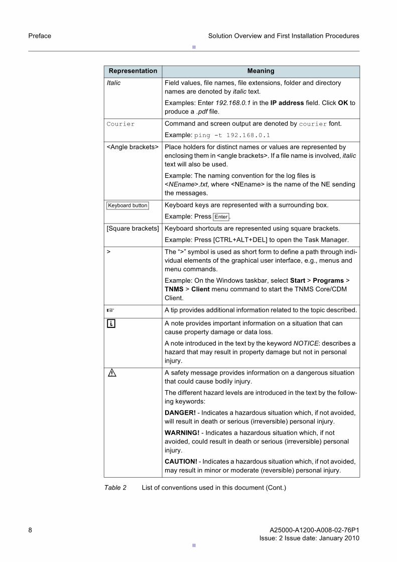
Italic Field values, file names, file extensions, folder and directory names are denoted by italic text.
Examples: Enter 192.168.0.1 in the IP address field. Click OK to produce a .pdf file.
Courier Command and screen output are denoted by courier font.
Example: ping -t 192.168.0.1<Angle brackets> Place holders for distinct names or values are represented by
enclosing them in <angle brackets>. If a file name is involved, italic text will also be used.
Example: The naming convention for the log files is <NEname>.txt, where <NEname> is the name of the NE sending the messages.
Keyboard button Keyboard keys are represented with a surrounding box.
Example: Press Enter .
[Square brackets] Keyboard shortcuts are represented using square brackets.
Example: Press [CTRL+ALT+DEL] to open the Task Manager.
> The “>” symbol is used as short form to define a path through indi-vidual elements of the graphical user interface, e.g., menus and menu commands.
Example: On the Windows taskbar, select Start > Programs > TNMS > Client menu command to start the TNMS Core/CDM Client.
☞ A tip provides additional information related to the topic described.
g A note provides important information on a situation that can cause property damage or data loss.
A note introduced in the text by the keyword NOTICE: describes a hazard that may result in property damage but not in personal injury.
f A safety message provides information on a dangerous situation that could cause bodily injury.
The different hazard levels are introduced in the text by the follow-ing keywords:
DANGER! - Indicates a hazardous situation which, if not avoided, will result in death or serious (irreversible) personal injury.
WARNING! - Indicates a hazardous situation which, if not avoided, could result in death or serious (irreversible) personal injury.
CAUTION! - Indicates a hazardous situation which, if not avoided, may result in minor or moderate (reversible) personal injury.
Representation Meaning
Table 2 List of conventions used in this document (Cont.)
.
.
A25000-A1200-A008-02-76P1Issue: 2 Issue date: January 2010
9
Solution Overview and First Installation Procedures Preface
Screenshots of the graphical user interface are examples only to illustrate principles. This especially applies to a software version number visible in a screenshot.
1.4 History of changes
1.5 Waste electrical and electronic equipment (WEEE)All waste electrical and electronic products must be disposed of separately from the municipal waste stream via designated collection facilities appointed by the government or the local authorities. The WEEE label (see Figure 1) is applied to all such devices.
Figure 1 WEEE label
The correct disposal and separate collection of waste equipment will help prevent poten-tial negative consequences for the environment and human health. It is a precondition for reuse and recycling of used electrical and electronic equipment.
For more detailed information about disposal of such equipment, please contact Nokia Siemens Networks.
The above statements are fully valid only for equipment installed in the countries of the European Union and is covered by the directive 2002/96/EC. Countries outside the European Union may have other regulations regarding the disposal of electrical and electronic equipment.
1.6 RoHS complianceFlexiPacket Radio complies with the European Union RoHS Directive 2002/95/EC on the restriction of use of certain hazardous substances in electrical and electronic equip-ment.
The directive applies to the use of lead, mercury, cadmium, hexavalent chromium, poly-brominated biphenyls (PBB), and polybrominated diphenylethers (PBDE) in electrical and electronic equipment put on the market after 1 July 2006.
Issue Issue date Remarks
1 November 2009 1st version
2 January 2010 – Some changes in the procedure of Chapter 2 have been inserted;
– the new Chapter 4 has been inserted.
Table 3 History of changes

.
.10 A25000-A1200-A008-02-76P1Issue: 2 Issue date: January 2010
Solution Overview and First Installation ProceduresPreface
Materials usage information on Nokia Siemens Networks Electronic Information Products imported or sold in the People’s Republic of ChinaFlexiPacket Radio complies with the Chinese standard SJ/T 11364-2006 on the restric-tion of the use of certain hazardous substances in electrical and electronic equipment. The standard applies to the use of lead, mercury, cadmium, hexavalent chromium, poly-brominated biphenyls (PBB), and polybrominated diphenyl ethers (PBDE) in electrical and electronic equipment put on the market after 1 March 2007.
.
.
A25000-A1200-A008-02-76P1Issue: 2 Issue date: January 2010
11
Solution Overview and First Installation Procedures FlexiPacket Microwave scenario (FP10)
2 FlexiPacket Microwave scenario (FP10)
2.1 OverviewThe basic concept behind the unique value proposition of FlexiPacket Microwave is the implementation of a complete microwave terminal in an Outdoor Unit.
This concept has been implemented in the FlexiPacket Radio.
While traditional MW equipment has a functional split between an Indoor (IDU) and an Outdoor (ODU) units in FlexiPacket Radio all the functionalitis, including modem and baseband processing are embedded in the ODU.
A standard Ethernet interface is used to interconnect with the network.
FlexiPacket Microwave is the means of deploying a cost-effective microwave infrastruc-ture for 3G, WiMAX and LTE backhaul, high speed wireless Internet networks, fixed broadband access backhaul and private wireless networks.
FlexiPacket Microwave is the right solution to design advanced mobile backhaul networks based on Ethernet transport. The solution is conceived both for pure packet and hybrid (TDM+packet) networks.
FlexiPacket Microwave includes:
– FlexiPacket Radio (a fully outdoor microwave radio)– FlexiPacket Hub 2200 (an indoor Carrier Ethernet switch)
FlexiPacket Hub is a carrier grade Ethernet switch, which supports multiple radio direc-tions. The resulting solution is a best-in-class microwave radio node.
In an unmatched compact design, it offers advanced Ethernet processing features as well as maximum flexibility to support TDM traffic via circuit emulation.
Access interfaces include Fast and Gigabit Ethernet, E1 and channelized STM-1.
Unique reliability is achieved thanks to the state of the art technology and support of pro-tected configurations, TDM tributary protection and Ethernet protection.
The modular architecture makes FlexiPacket Hub very flexible and pay-as-you-grow. Additionally, the FlexiPacket Hub, as part of the Nokia Siemens Networks Carrier Ethernet portfolio, allows a smooth integration in the network, ensuring end to end QoS and easy provisioning.
2.2 First installation proceduresThis chapter gives the procedures to install for the first time (starting from a scratch con-figuration) the FlexiPacket Microwave (made up of one FlexiPacket Hub 2200 and one or more FlexiPacket Radios SVR 1.2, connecteced to the FlexiPacket Hub).
☞ In case you have FlexiPacket Radio with SVR 1.1 please refer to FlexiPacket Radio “Operate and Maintenance” manual > Software Download and upgrade the ODU to SVR 1.2.
☞ If something goes as not expected in the procedure, plase restart from scratch by appling the following command via CLI: clear config remote start-up.
☞ In case of 1+1 protected link, the ETH ports used on the HUB must be one even number and the other odd number.
.
.12 A25000-A1200-A008-02-76P1Issue: 2 Issue date: January 2010
Solution Overview and First Installation ProceduresFlexiPacket Microwave scenario (FP10)
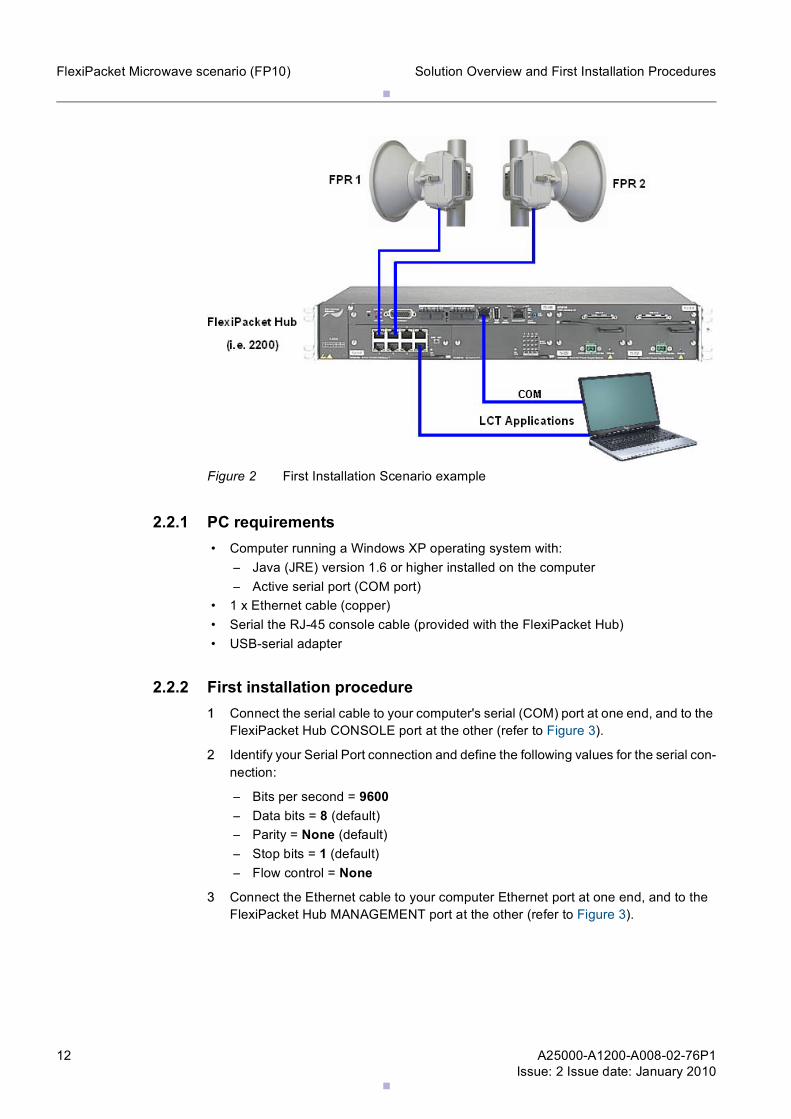
Figure 2 First Installation Scenario example
2.2.1 PC requirements • Computer running a Windows XP operating system with:
– Java (JRE) version 1.6 or higher installed on the computer– Active serial port (COM port)
• 1 x Ethernet cable (copper) • Serial the RJ-45 console cable (provided with the FlexiPacket Hub) • USB-serial adapter
2.2.2 First installation procedure1 Connect the serial cable to your computer's serial (COM) port at one end, and to the
FlexiPacket Hub CONSOLE port at the other (refer to Figure 3).
2 Identify your Serial Port connection and define the following values for the serial con-nection:
– Bits per second = 9600– Data bits = 8 (default)– Parity = None (default)– Stop bits = 1 (default)– Flow control = None
3 Connect the Ethernet cable to your computer Ethernet port at one end, and to the FlexiPacket Hub MANAGEMENT port at the other (refer to Figure 3).
.
.
A25000-A1200-A008-02-76P1Issue: 2 Issue date: January 2010
13
Solution Overview and First Installation Procedures FlexiPacket Microwave scenario (FP10)
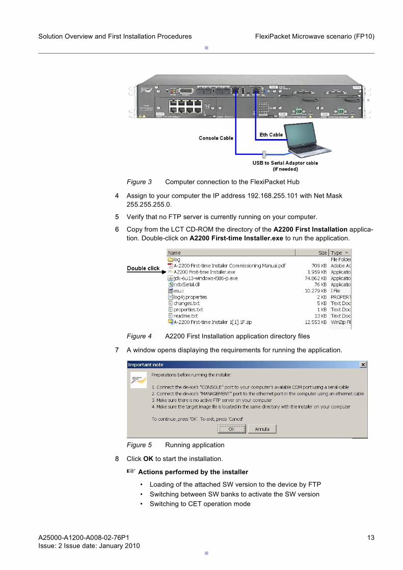
Figure 3 Computer connection to the FlexiPacket Hub
4 Assign to your computer the IP address 192.168.255.101 with Net Mask 255.255.255.0.
5 Verify that no FTP server is currently running on your computer.
6 Copy from the LCT CD-ROM the directory of the A2200 First Installation applica-tion. Double-click on A2200 First-time Installer.exe to run the application.
Figure 4 A2200 First Installation application directory files
7 A window opens displaying the requirements for running the application.
Figure 5 Running application
8 Click OK to start the installation.
☞ Actions performed by the installer
• Loading of the attached SW version to the device by FTP • Switching between SW banks to activate the SW version • Switching to CET operation mode
.
.14 A25000-A1200-A008-02-76P1Issue: 2 Issue date: January 2010
Solution Overview and First Installation ProceduresFlexiPacket Microwave scenario (FP10)
• Configuring the required SNMP community parameters • Configuring port 1/8 for (slot 1/port 8) inband connectivity and enable its
admin-state
☞ A reset is required for both switching between SW banks and switching between operation modes. These resets are performed automatically; the relevant notifi-cations appear in the application window.
☞ While the installer is running, various verifications of the setup, such as IP vali-dations, COM port connectivity check, etc., are carried out. If a problem occurs, a message describing the problem will appear. You are requested to fix the problem and run the application again.
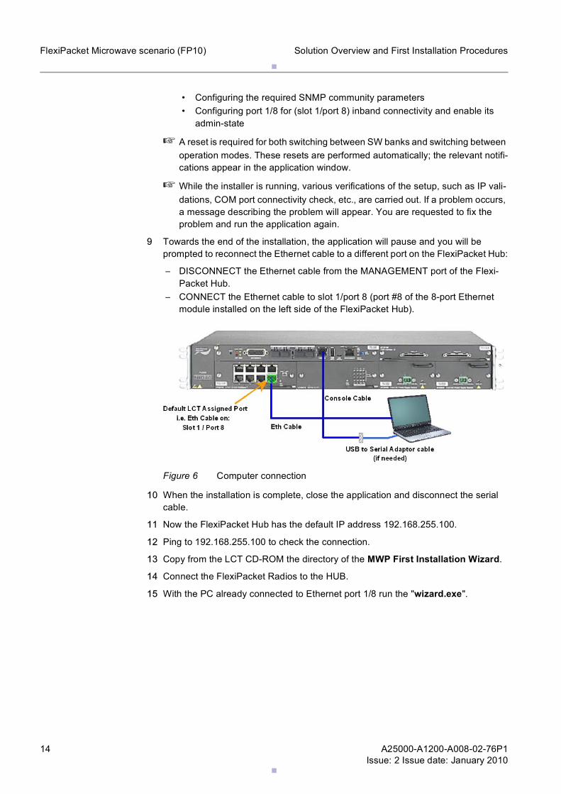
9 Towards the end of the installation, the application will pause and you will be prompted to reconnect the Ethernet cable to a different port on the FlexiPacket Hub:
– DISCONNECT the Ethernet cable from the MANAGEMENT port of the Flexi-Packet Hub.
– CONNECT the Ethernet cable to slot 1/port 8 (port #8 of the 8-port Ethernet module installed on the left side of the FlexiPacket Hub).
Figure 6 Computer connection
10 When the installation is complete, close the application and disconnect the serial cable.
11 Now the FlexiPacket Hub has the default IP address 192.168.255.100.
12 Ping to 192.168.255.100 to check the connection.
13 Copy from the LCT CD-ROM the directory of the MWP First Installation Wizard.
14 Connect the FlexiPacket Radios to the HUB.
15 With the PC already connected to Ethernet port 1/8 run the "wizard.exe".
.
.
A25000-A1200-A008-02-76P1Issue: 2 Issue date: January 2010
15
Solution Overview and First Installation Procedures FlexiPacket Microwave scenario (FP10)
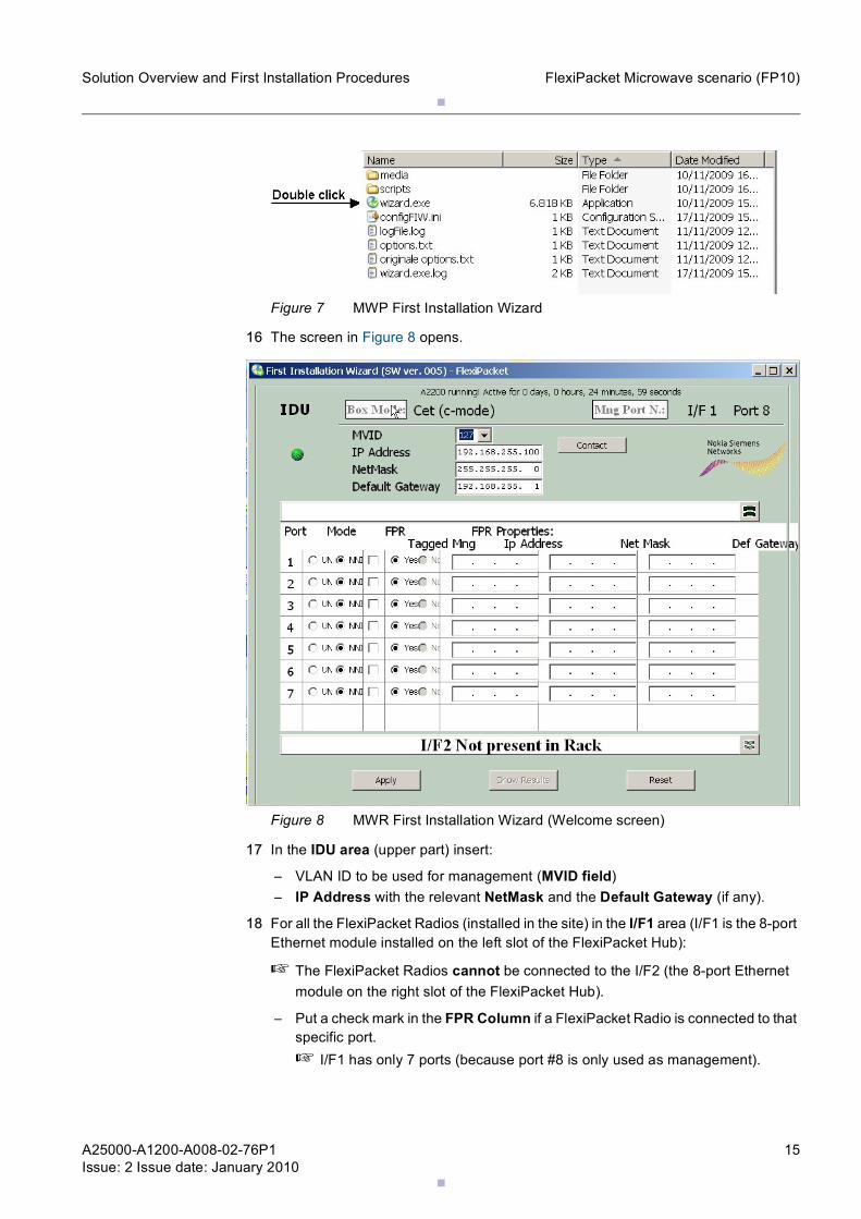
Figure 7 MWP First Installation Wizard
16 The screen in Figure 8 opens.
Figure 8 MWR First Installation Wizard (Welcome screen)
17 In the IDU area (upper part) insert:
– VLAN ID to be used for management (MVID field)– IP Address with the relevant NetMask and the Default Gateway (if any).
18 For all the FlexiPacket Radios (installed in the site) in the I/F1 area (I/F1 is the 8-port Ethernet module installed on the left slot of the FlexiPacket Hub):
☞ The FlexiPacket Radios cannot be connected to the I/F2 (the 8-port Ethernet module on the right slot of the FlexiPacket Hub).
– Put a check mark in the FPR Column if a FlexiPacket Radio is connected to that specific port.☞ I/F1 has only 7 ports (because port #8 is only used as management).
.
.16 A25000-A1200-A008-02-76P1Issue: 2 Issue date: January 2010
Solution Overview and First Installation ProceduresFlexiPacket Microwave scenario (FP10)
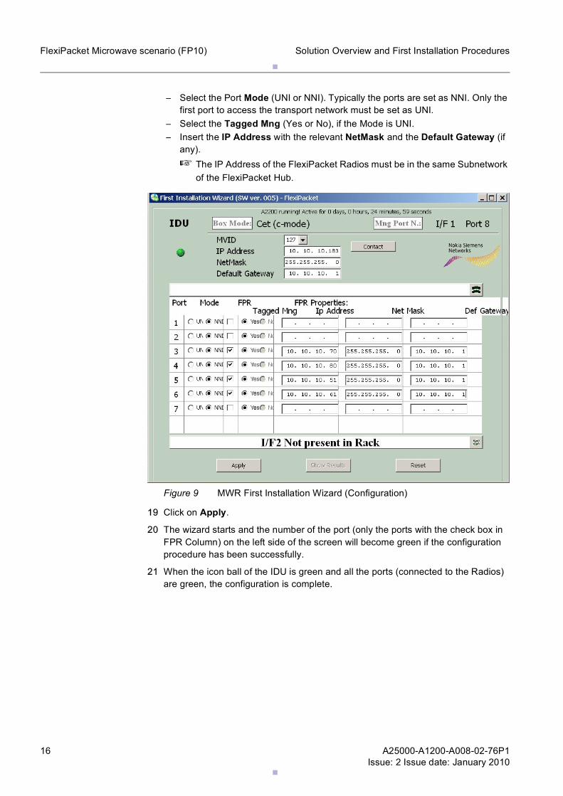
– Select the Port Mode (UNI or NNI). Typically the ports are set as NNI. Only the first port to access the transport network must be set as UNI.
– Select the Tagged Mng (Yes or No), if the Mode is UNI.– Insert the IP Address with the relevant NetMask and the Default Gateway (if
any).☞ The IP Address of the FlexiPacket Radios must be in the same Subnetwork
of the FlexiPacket Hub.
Figure 9 MWR First Installation Wizard (Configuration)
19 Click on Apply.
20 The wizard starts and the number of the port (only the ports with the check box in FPR Column) on the left side of the screen will become green if the configuration procedure has been successfully.
21 When the icon ball of the IDU is green and all the ports (connected to the Radios) are green, the configuration is complete.
.
.
A25000-A1200-A008-02-76P1Issue: 2 Issue date: January 2010
17
Solution Overview and First Installation Procedures FlexiPacket Microwave scenario (FP10)
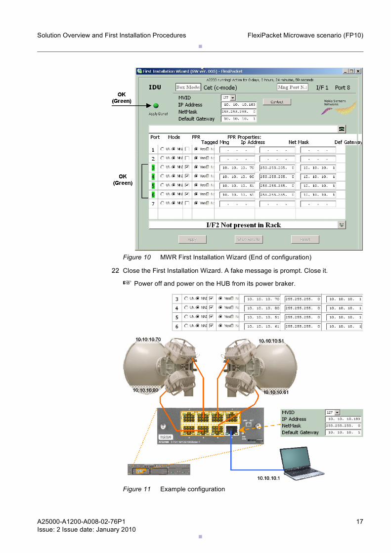
Figure 10 MWR First Installation Wizard (End of configuration)
22 Close the First Installation Wizard. A fake message is prompt. Close it.
☞ Power off and power on the HUB from its power braker.
Figure 11 Example configuration
.
.18 A25000-A1200-A008-02-76P1Issue: 2 Issue date: January 2010
Solution Overview and First Installation ProceduresFlexiPacket Microwave scenario (FP10)
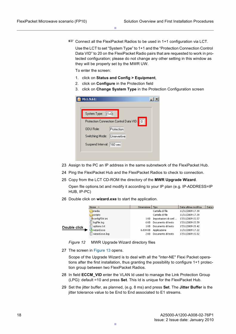
☞ Connect all the FlexiPacket Radios to be used in 1+1 configuration via LCT.
Use the LCT to set “System Type” to 1+1 and the “Protection Connection Control Data VID” to 20 on the FlexiPacket Radio pairs that are requested to work in pro-tected configuration; please do not change any other setting in this window as they will be properly set by the MWR UW.
To enter the screen:
1. click on Status and Config > Equipment,2. click on Configure in the Protection field 3. click on Change System Type in the Protection Configuration screen
23 Assign to the PC an IP address in the same subnetwork of the FlexiPacket Hub.
24 Ping the FlexiPacket Hub and the FlexiPacket Radios to check to connection.
25 Copy from the LCT CD-ROM the directory of the MWR Upgrade Wizard.
Open file options.txt and modify it according to your IP plan (e.g. IP-ADDRESS=IP HUB, IP-PC)
26 Double click on wizard.exe to start the application.
Figure 12 MWR Upgrade Wizard directory files
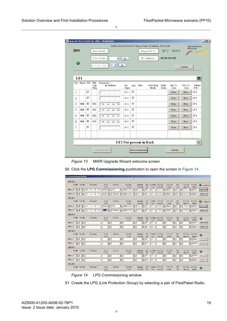
27 The screen in Figure 13 opens.
Scope of the Upgrade Wizard is to deal with all the "inter-NE" Flexi Packet opera-tions after the first installation, thus granting the possibility to configure 1+1 protec-tion group between two FlexiPacket Radios.
28 In field ECCM_VID enter the VLAN Id used to manage the Link Protection Group (LPG): default =10 and press Set. This Id is unique for the FlexiPacket Hub.
29 Set the jitter buffer, as planned, (e.g. 8 ms) and press Set. The Jitter Buffer is the jitter tolerance value to be End to End associated to E1 streams.
.
.
A25000-A1200-A008-02-76P1Issue: 2 Issue date: January 2010
19
Solution Overview and First Installation Procedures FlexiPacket Microwave scenario (FP10)
Figure 13 MWR Upgrade Wizard welcome screen
30 Click the LPG Commissioning pushbutton to open the screen in Figure 14.
Figure 14 LPG Commissioning window
31 Create the LPG (Link Protection Group) by selecting a pair of FlexiPaket Radio.
.
.20 A25000-A1200-A008-02-76P1Issue: 2 Issue date: January 2010
Solution Overview and First Installation ProceduresFlexiPacket Microwave scenario (FP10)
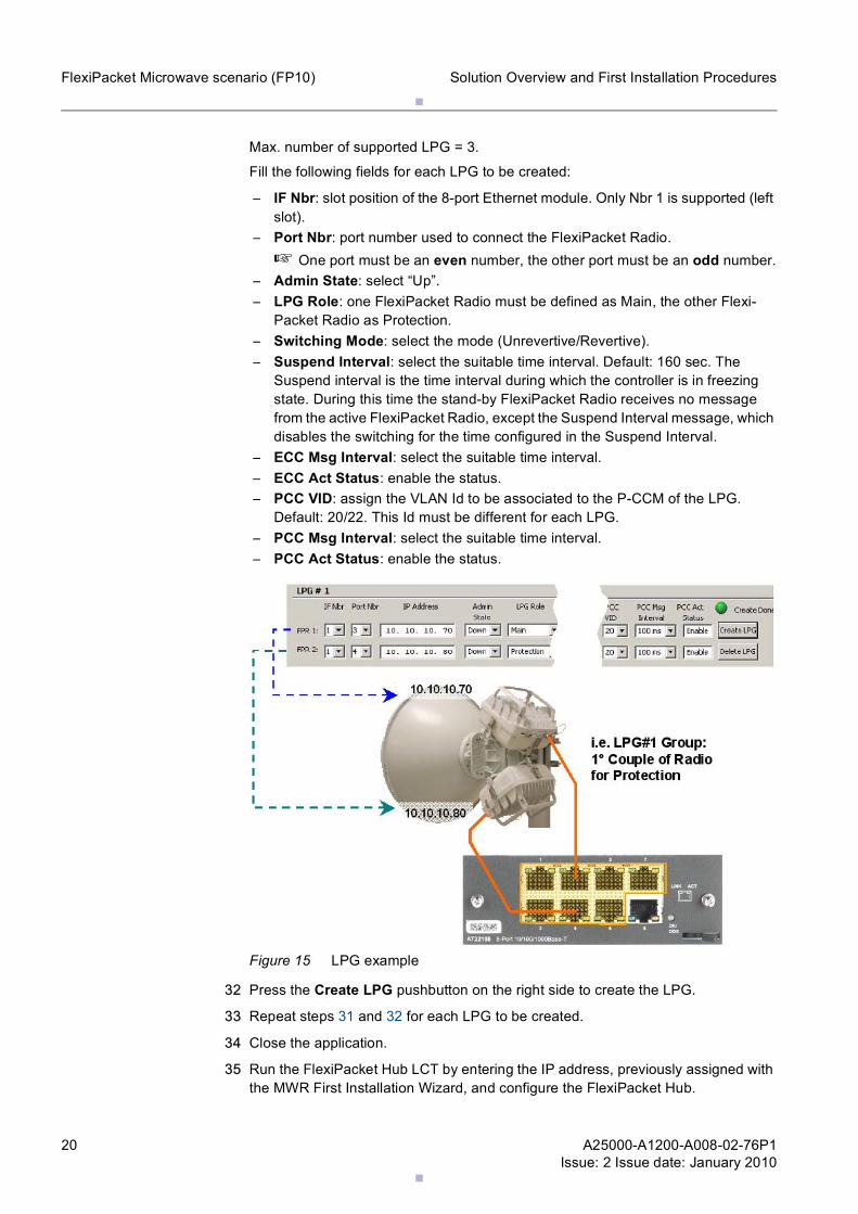
Max. number of supported LPG = 3.
Fill the following fields for each LPG to be created:
– IF Nbr: slot position of the 8-port Ethernet module. Only Nbr 1 is supported (left slot).
– Port Nbr: port number used to connect the FlexiPacket Radio.☞ One port must be an even number, the other port must be an odd number.
– Admin State: select “Up”.– LPG Role: one FlexiPacket Radio must be defined as Main, the other Flexi-
Packet Radio as Protection.– Switching Mode: select the mode (Unrevertive/Revertive).– Suspend Interval: select the suitable time interval. Default: 160 sec. The
Suspend interval is the time interval during which the controller is in freezing state. During this time the stand-by FlexiPacket Radio receives no message from the active FlexiPacket Radio, except the Suspend Interval message, which disables the switching for the time configured in the Suspend Interval.
– ECC Msg Interval: select the suitable time interval.– ECC Act Status: enable the status.– PCC VID: assign the VLAN Id to be associated to the P-CCM of the LPG.
Default: 20/22. This Id must be different for each LPG.– PCC Msg Interval: select the suitable time interval.– PCC Act Status: enable the status.
Figure 15 LPG example
32 Press the Create LPG pushbutton on the right side to create the LPG.
33 Repeat steps 31 and 32 for each LPG to be created.
34 Close the application.
35 Run the FlexiPacket Hub LCT by entering the IP address, previously assigned with the MWR First Installation Wizard, and configure the FlexiPacket Hub.
.
.
A25000-A1200-A008-02-76P1Issue: 2 Issue date: January 2010
21
Solution Overview and First Installation Procedures FlexiPacket Microwave scenario (FP10)
Refer to chapter 2.3 FlexiPacket Hub configuration.
36 Run the FlexiPacket Radio LCT by entering the IP address, previously assigned with the First Installation Wizard, and configure the FlexiPacket Radios. Refer to the FlexiPacket Radio Commission document.
37 Configure the synchronisms via CLI, once the radio link has been configured. For the procedure refer to Chapter 4.
2.3 FlexiPacket Hub configurationThis chapter gives the information to configure the FlaxiPacket Hub.
Steps
1 Start the LCT:Start > All Programs > Nokia Siemens Networks > LCT > LCT
2 Open the LOCALNE_SNMP.map:File > Open Map > Select LOCALNE_SNMP.map
3 Right click on the FlexiPacket Hub icon.
4 The Open NE screen opens.
5 Enter:
– User Class: Read & Write– Password: private
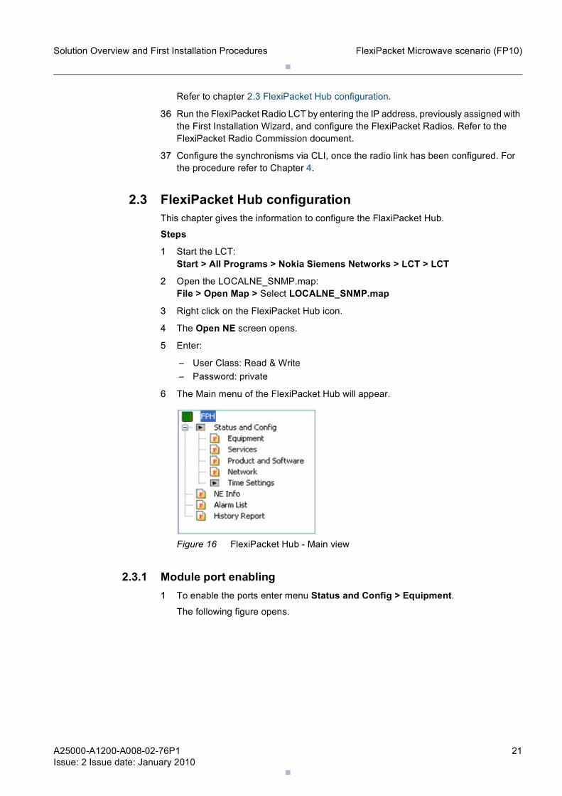
6 The Main menu of the FlexiPacket Hub will appear.
Figure 16 FlexiPacket Hub - Main view
2.3.1 Module port enabling1 To enable the ports enter menu Status and Config > Equipment.
The following figure opens.
.
.22 A25000-A1200-A008-02-76P1Issue: 2 Issue date: January 2010
Solution Overview and First Installation ProceduresFlexiPacket Microwave scenario (FP10)
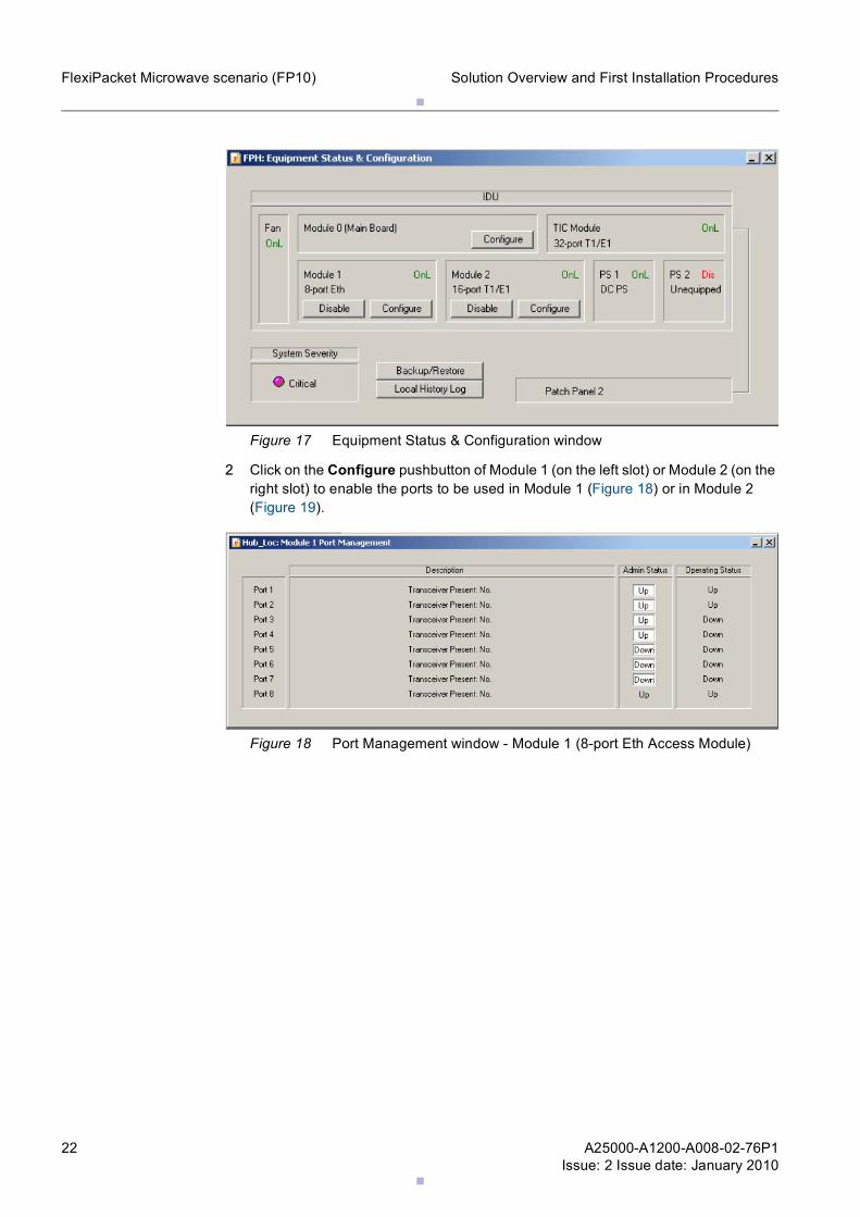
Figure 17 Equipment Status & Configuration window
2 Click on the Configure pushbutton of Module 1 (on the left slot) or Module 2 (on the right slot) to enable the ports to be used in Module 1 (Figure 18) or in Module 2 (Figure 19).
Figure 18 Port Management window - Module 1 (8-port Eth Access Module)
.
.
A25000-A1200-A008-02-76P1Issue: 2 Issue date: January 2010
23
Solution Overview and First Installation Procedures FlexiPacket Microwave scenario (FP10)
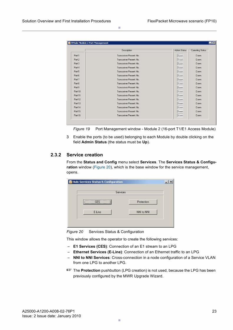
Figure 19 Port Management window - Module 2 (16-port T1/E1 Access Module)
3 Enable the ports (to be used) belonging to each Module by double clicking on the field Admin Status (the status must be Up).
2.3.2 Service creationFrom the Status and Config menu select Services. The Services Status & Configu-ration window (Figure 20), which is the base window for the service management, opens.
Figure 20 Services Status & Configuration
This window allows the operator to create the following services:
– E1 Services (CES): Connection of an E1 stream to an LPG– Ethernet Services (E-Line): Connection of an Ethernet traffic to an LPG– NNI to NNI Services: Cross-connection in a node configuration of a Service VLAN
from one LPG to another LPG.
☞ The Protection pushbutton (LPG creation) is not used, because the LPG has been previously configured by the MWR Upgrade Wizard.
.
.24 A25000-A1200-A008-02-76P1Issue: 2 Issue date: January 2010
Solution Overview and First Installation ProceduresFlexiPacket Microwave scenario (FP10)
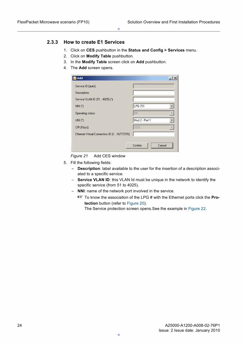
2.3.3 How to create E1 Services1. Click on CES pushbutton in the Status and Config > Services menu.2. Click on Modify Table pushbutton.3. In the Modify Table screen click on Add pushbutton.4. The Add screen opens.
Figure 21 Add CES window5. Fill the following fields:
– Description: label available to the user for the insertion of a description associ-ated to a specific service.
– Service VLAN ID: this VLAN Id must be unique in the network to identify the specific service (from 51 to 4025).
– NNI: name of the network port involved in the service.☞ To know the association of the LPG # with the Ethernet ports click the Pro-
tection button (refer to Figure 20). The Service protection screen opens.See the example in Figure 22.
.
.
A25000-A1200-A008-02-76P1Issue: 2 Issue date: January 2010
25
Solution Overview and First Installation Procedures FlexiPacket Microwave scenario (FP10)
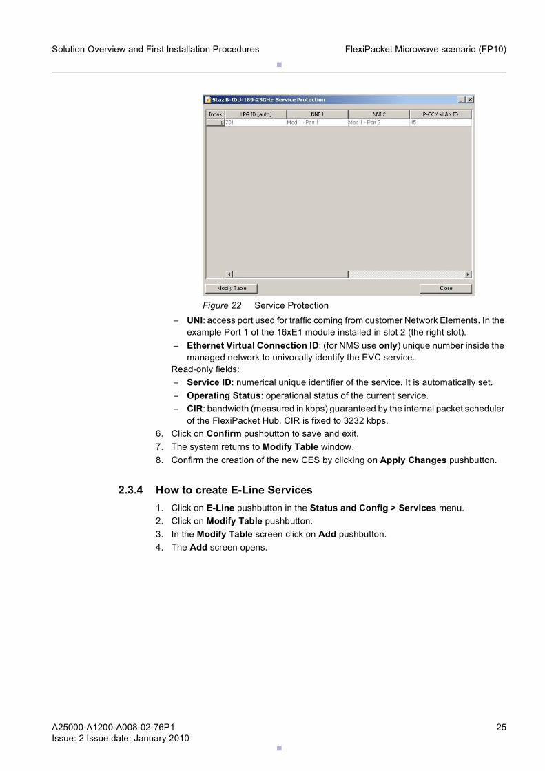
Figure 22 Service Protection– UNI: access port used for traffic coming from customer Network Elements. In the
example Port 1 of the 16xE1 module installed in slot 2 (the right slot).– Ethernet Virtual Connection ID: (for NMS use only) unique number inside the
managed network to univocally identify the EVC service.Read-only fields:– Service ID: numerical unique identifier of the service. It is automatically set.– Operating Status: operational status of the current service.– CIR: bandwidth (measured in kbps) guaranteed by the internal packet scheduler
of the FlexiPacket Hub. CIR is fixed to 3232 kbps.6. Click on Confirm pushbutton to save and exit.7. The system returns to Modify Table window.8. Confirm the creation of the new CES by clicking on Apply Changes pushbutton.
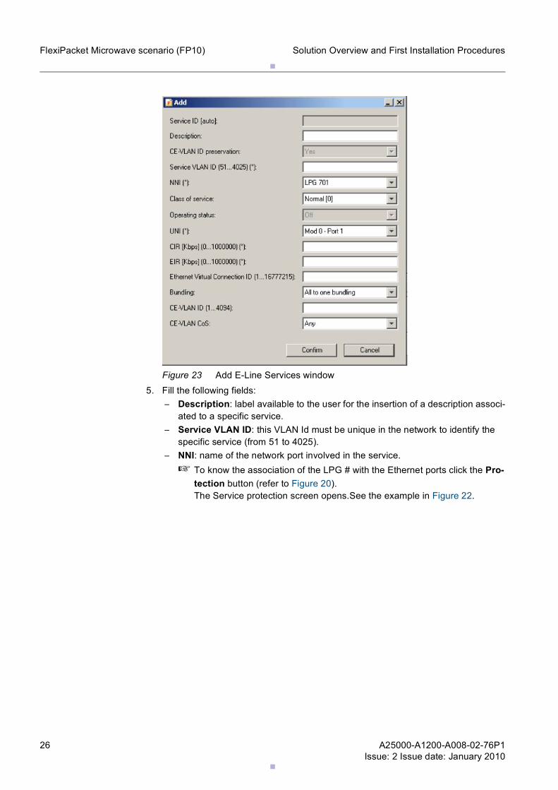
2.3.4 How to create E-Line Services1. Click on E-Line pushbutton in the Status and Config > Services menu.2. Click on Modify Table pushbutton.3. In the Modify Table screen click on Add pushbutton.4. The Add screen opens.
.
.26 A25000-A1200-A008-02-76P1Issue: 2 Issue date: January 2010
Solution Overview and First Installation ProceduresFlexiPacket Microwave scenario (FP10)
Figure 23 Add E-Line Services window5. Fill the following fields:
– Description: label available to the user for the insertion of a description associ-ated to a specific service.
– Service VLAN ID: this VLAN Id must be unique in the network to identify the specific service (from 51 to 4025).
– NNI: name of the network port involved in the service.☞ To know the association of the LPG # with the Ethernet ports click the Pro-
tection button (refer to Figure 20). The Service protection screen opens.See the example in Figure 22.
.
.
A25000-A1200-A008-02-76P1Issue: 2 Issue date: January 2010
27
Solution Overview and First Installation Procedures FlexiPacket Microwave scenario (FP10)
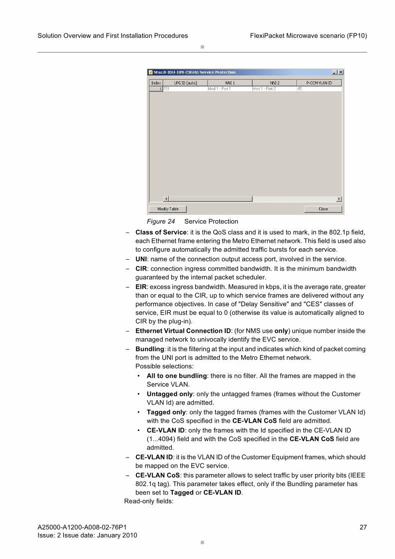
Figure 24 Service Protection– Class of Service: it is the QoS class and it is used to mark, in the 802.1p field,
each Ethernet frame entering the Metro Ethernet network. This field is used also to configure automatically the admitted traffic bursts for each service.
– UNI: name of the connection output access port, involved in the service.– CIR: connection ingress committed bandwidth. It is the minimum bandwidth
guaranteed by the internal packet scheduler.– EIR: excess ingress bandwidth. Measured in kbps, it is the average rate, greater
than or equal to the CIR, up to which service frames are delivered without any performance objectives. In case of "Delay Sensitive" and "CES" classes of service, EIR must be equal to 0 (otherwise its value is automatically aligned to CIR by the plug-in).
– Ethernet Virtual Connection ID: (for NMS use only) unique number inside the managed network to univocally identify the EVC service.
– Bundling: it is the filtering at the input and indicates which kind of packet coming from the UNI port is admitted to the Metro Ethernet network. Possible selections: • All to one bundling: there is no filter. All the frames are mapped in the
Service VLAN. • Untagged only: only the untagged frames (frames without the Customer
VLAN Id) are admitted. • Tagged only: only the tagged frames (frames with the Customer VLAN Id)
with the CoS specified in the CE-VLAN CoS field are admitted. • CE-VLAN ID: only the frames with the Id specified in the CE-VLAN ID
(1...4094) field and with the CoS specified in the CE-VLAN CoS field are admitted.
– CE-VLAN ID: it is the VLAN ID of the Customer Equipment frames, which should be mapped on the EVC service.
– CE-VLAN CoS: this parameter allows to select traffic by user priority bits (IEEE 802.1q tag). This parameter takes effect, only if the Bundling parameter has been set to Tagged or CE-VLAN ID.
Read-only fields:
.
.28 A25000-A1200-A008-02-76P1Issue: 2 Issue date: January 2010
Solution Overview and First Installation ProceduresFlexiPacket Microwave scenario (FP10)
– Service ID: numerical unique identifier of the service. It is automatically set.– CE-VLAN ID Preservation: it says if the Customer Equipment VLAN ID should
be preserved by means of VLAN Stacking during transmission over the metro Ethernet network.
– Operating status: operational status of the Ethernet service.6. Click on Confirm pushbutton to save and exit.7. The system returns to Modify Table window.8. Confirm the creation of the new E-Line Service by clicking on Apply Changes push-
button.
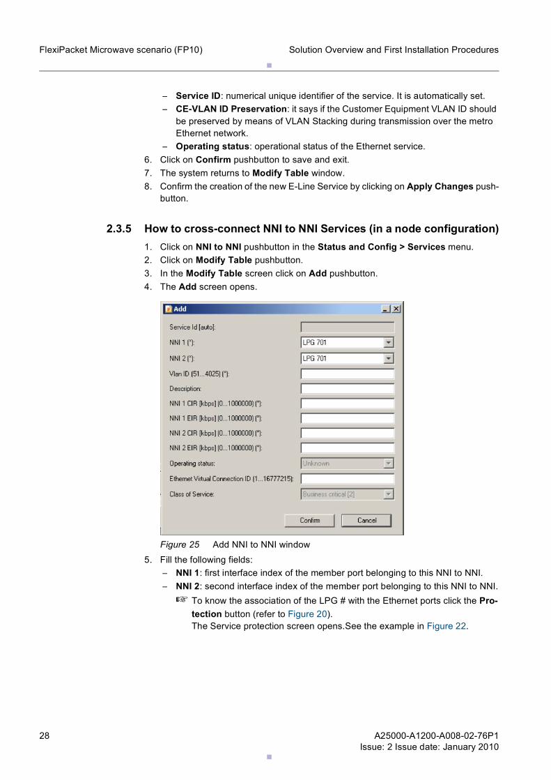
2.3.5 How to cross-connect NNI to NNI Services (in a node configuration)1. Click on NNI to NNI pushbutton in the Status and Config > Services menu.2. Click on Modify Table pushbutton.3. In the Modify Table screen click on Add pushbutton.4. The Add screen opens.
Figure 25 Add NNI to NNI window5. Fill the following fields:
– NNI 1: first interface index of the member port belonging to this NNI to NNI.– NNI 2: second interface index of the member port belonging to this NNI to NNI.
☞ To know the association of the LPG # with the Ethernet ports click the Pro-tection button (refer to Figure 20). The Service protection screen opens.See the example in Figure 22.
.
.
A25000-A1200-A008-02-76P1Issue: 2 Issue date: January 2010
29
Solution Overview and First Installation Procedures FlexiPacket Microwave scenario (FP10)
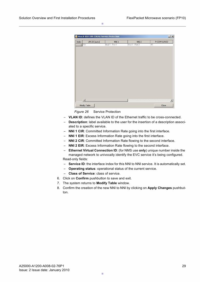
Figure 26 Service Protection– VLAN ID: defines the VLAN ID of the Ethernet traffic to be cross-connected.– Description: label available to the user for the insertion of a description associ-
ated to a specific service.– NNI 1 CIR: Committed Information Rate going into the first interface.– NNI 1 EIR: Excess Information Rate going into the first interface.– NNI 2 CIR: Committed Information Rate flowing to the second interface.– NNI 2 EIR: Excess Information Rate flowing to the second interface.– Ethernet Virtual Connection ID: (for NMS use only) unique number inside the
managed network to univocally identify the EVC service it’s being configured.Read-only fields:– Service ID: the interface index for this NNI to NNI service. It is automatically set.– Operating status: operational status of the current service.– Class of Service: class of service.
6. Click on Confirm pushbutton to save and exit.7. The system returns to Modify Table window.8. Confirm the creation of the new NNI to NNI by clicking on Apply Changes pushbut-
ton.
.
.30 A25000-A1200-A008-02-76P1Issue: 2 Issue date: January 2010
Solution Overview and First Installation ProceduresFlexiBTS scenario (RU10)
3 FlexiBTS scenario (RU10)
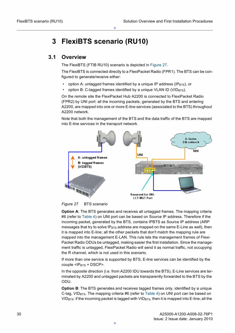
3.1 OverviewThe FlexiBTS (FTIB RU10) scenario is depicted in Figure 27.
The FlexiBTS is connected directly to a FlexiPacket Radio (FPR1). The BTS can be con-figured to generate/receive either:
• option A: untagged frames identified by a unique IP address (IPBTS), or • option B: C-tagged frames identified by a unique VLAN ID (VIDBTS).
On the remote site the FlexiPacket Hub A2200 is connected to FlexiPacket Radio (FPR2) by UNI port: all the incoming packets, generated by the BTS and entering A2200, are mapped into one or more E-line services (associated to the BTS) throughout A2200 network.
Note that both the management of the BTS and the data traffic of the BTS are mapped into E-line services in the transport network.
Figure 27 BTS scenario
Option A: The BTS generates and receives all untagged frames. The mapping criteria #6 (refer to Table 4) on UNI port can be based on Source IP address. Therefore if the incoming packet, generated by the BTS, contains IPBTS as Source IP address (ARP messages that try to solve IPBTS address are mapped on the same E-Line as well), then it is mapped into E-line; all the other packets that don't match the mapping rule are mapped into the management E-LAN. This rule lets the management frames of Flexi-Packet Radio ODUs be untagged, making easier the first installation. Since the manage-ment traffic is untagged, FlexiPacket Radio will send it as normal traffic, not occupying the R channel, which is not used in this scenario.
If more than one service is supported by BTS, E-line services can be identified by the couple <IPBTS + DSCP>.
In the opposite direction (i.e. from A2200 IDU towards the BTS), E-Line services are ter-minated by A2200 and untagged packets are transparently forwarded to the BTS by the ODU.
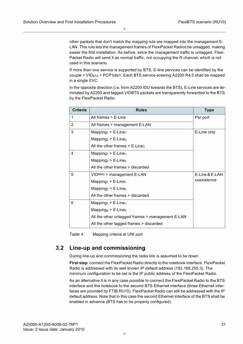
Option B: The BTS generates and receives tagged frames only, identified by a unique C-tag, VIDBTS. The mapping criteria #6 (refer to Table 4) on UNI port can be based on VIDBTS: if the incoming packet is tagged with VIDBTS, then it is mapped into E-line; all the
.
.
A25000-A1200-A008-02-76P1Issue: 2 Issue date: January 2010
31
Solution Overview and First Installation Procedures FlexiBTS scenario (RU10)
other packets that don't match the mapping rule are mapped into the management E-LAN. This rule lets the management frames of FlexiPacket Radios be untagged, making easier the first installation. As before, since the management traffic is untagged, Flexi-Packet Radio will send it as normal traffic, not occupying the R channel, which is not used in this scenario.
If more than one service is supported by BTS, E-line services can be identified by the couple < VIDBTS + PCP bits>. Each BTS service entering A2200 R4.5 shall be mapped in a single EVC.
In the opposite direction (i.e. from A2200 IDU towards the BTS), E-Line services are ter-minated by A2200 and tagged VIDBTS packets are transparently forwarded to the BTS by the FlexiPacket Radio.
3.2 Line-up and commissioningDuring line-up and commissioning the radio link is assumed to be down.
First step: connect the FlexiPacket Radio directly to the notebook interface. FlexiPacket Radio is addressed with its well known IP default address (192.168.255.3). The minimum configuration to be set is the IP public address of the FlexiPacket Radio.
As an alternative it is in any case possible to connect the FlexiPacket Radio to the BTS interface and the notebook to the second BTS Ethernet interface (three Ethernet inter-faces are provided by FTIB RU10). FlexiPacket Radio can still be addressed with the IP default address. Note that in this case the second Ethernet interface of the BTS shall be enabled in advance (BTS has to be properly configured).
Criteria Rules Type
1 All frames > E-Line Per port
2 All frames > management E-LAN
3 Mapping1 > E-Line1
Mapping2 > E-Line2
All the other frames > E-Line3
E-Line only
4 Mapping1 > E-Line1
Mapping2 > E-Line2
All the other frames > discarded
5 VIDMNG > management E-LAN
Mapping1 > E-Line1
Mapping2 > E-Line2
All the other frames > discarded
E-Line & E-LAN coexistence
6 Mapping1 > E-Line1
Mapping2 > E-Line2
All the other untagged frames > management E-LAN
All the other tagged frames > discarded
Table 4 Mapping criteria at UNI port
.
.32 A25000-A1200-A008-02-76P1Issue: 2 Issue date: January 2010
Solution Overview and First Installation ProceduresFlexiBTS scenario (RU10)
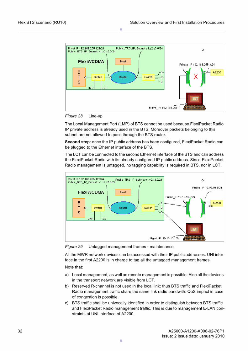
Figure 28 Line-up
The Local Management Port (LMP) of BTS cannot be used because FlexiPacket Radio IP private address is already used in the BTS. Moreover packets belonging to this subnet are not allowed to pass through the BTS router.
Second step: once the IP public address has been configured, FlexiPacket Radio can be plugged to the Ethernet interface of the BTS.
The LCT can be connected to the second Ethernet interface of the BTS and can address the FlexiPacket Radio with its already configured IP public address. Since FlexiPacket Radio management is untagged, no tagging capability is required in BTS, nor in LCT.
Figure 29 Untagged management frames - maintenance
All the MWR network devices can be accessed with their IP public addresses. UNI inter-face in the first A2200 is in charge to tag all the untagged management frames.
Note that:
a) Local management, as well as remote management is possible. Also all the devices in the transport network are visible from LCT.
b) Reserved R-channel is not used in the local link: thus BTS traffic and FlexiPacket Radio management traffic share the same link radio bandwith. QoS impact in case of congestion is possible.
c) BTS traffic shall be univocally identified in order to distinguish between BTS traffic and FlexiPacket Radio management traffic. This is due to management E-LAN con-straints at UNI interface of A2200.

.
.
A25000-A1200-A008-02-76P1Issue: 2 Issue date: January 2010
33
Solution Overview and First Installation Procedures FlexiBTS scenario (RU10)
d) The second Ethernet interface in the BTS must be available. This is OK in first issue since chain scenario is not foreseen.
.
.34 A25000-A1200-A008-02-76P1Issue: 2 Issue date: January 2010
Solution Overview and First Installation ProceduresSynchronous Ethernet configuration procedure for FlexiPacket single link solution during first installation
4 Synchronous Ethernet configuration proce-dure for FlexiPacket single link solution during first installation and commissioning
4.1 IntroductionThis chapter is designed for describing the configuration procedure of a single Flexi-Packet solution radio link when synchronization distribution must be implemented using Synchronous Ethernet feature.
☞ this document is designed to be used only during single link first installation and commissioning, in order to have a working synchronization configuration, able to support a single test CES service to be monitored for single link acceptance.
The procedure considers the aforementioned test CES service running between inter-face E1 x/y of the first FlexiPacket Hub and interface x'/y' of the second FlexiPacket Hub.
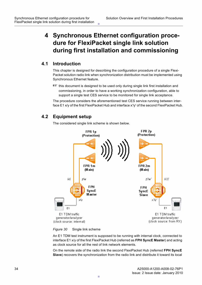
4.2 Equipment setupThe considered single link scheme is shown below.
Figure 30 Single link scheme
An E1 TDM test instrument is supposed to be running with internal clock, connected to interface E1 x/y of the first FlexiPacket Hub (referred as FPH SyncE Master) and acting as clock source for all the rest of link network elements.
On the remote side of the radio link the second FlexiPacket Hub (referred FPH SyncE Slave) recovers the synchronization from the radio link and distribute it toward its local
.
.
A25000-A1200-A008-02-76P1Issue: 2 Issue date: January 2010
35
Solution Overview and First Installation Procedures Synchronous Ethernet configuration procedure forFlexiPacket single link solution during first installation
E1 interfaces, which have a paired E1 TDM test instrument connected to interface E1 x'/y' and running with clock recovered from RX.
The scheme is reporting a 1+1 protected radio link with on LPG on each side.
In case of 1+0 unprotected radio link please do not consider FPR 1p and FPR 2p con-nected to k/j and k'/j' interfaces.
The interface numbering reported in the scheme must be adapted to the actual interface numbering used on field.
4.3 Procedure1 Using LCT enable the Administrative State of interface x/y, z/w and k/j (if the LPG is
configured) of FPH SyncE Master.
2 Connect by CLI to the FPH SyncE Master by logging in with:
– username: root– password: root
3 In FPH SyncE Master CLI execute the following commands:
– config-set ces system clock add line x/y ssm_ql prs priority 1(selects slot x port y as reference system clock of the FPH)
– config-set ces system clock wait_to_restore_time 60(set the wait to restore time for the reference system clock after failure recovery)
– config-set interface ethernet z/w ssm-state enabled(enables SSM messages on slot z port w, that is the Ethernet port where FPR is connected to)
– config-set interface access ds1 x/y clock system(selects the reference system clock as the egress clock for slot x port y, that is the CES card)
– config-set interface ethernet z/w clk-negotiation master(set slot z port w, that is the Ethernet port where FPR is connected to, as Master for SyncE)
4 Please note that, in case of LPG, synchronization settings must be replicated also on the second port of the LPG.
In FPH SyncE Master, also the second port of the LPG must be configured as the first one, so execute the following commands in its CLI only in case of LPG:
– config-set interface ethernet k/j ssm-state enabled(enables SSM messages on slot k port j, that is the Ethernet port where the second FPR of the LPG is connected to)
– config-set interface ethernet k/j clk-negotiation master(set slot k port j, that is the Ethernet port where the second FPR of the LPG is connected to, as Master for SyncE)
5 Verify that FPH SyncE Master is correctly configured executing the following commands in its CLI:
– show ces system clock info– show interface ethernet * clk- negotiation– show interface ethernet * ssm-info
The CES system clock should be Locked on Line x/y, which should be Valid.
.
.36 A25000-A1200-A008-02-76P1Issue: 2 Issue date: January 2010
Solution Overview and First Installation ProceduresSynchronous Ethernet configuration procedure for FlexiPacket single link solution during first installation
The Ethernet z/w interface should be reported as Master.
In case of LPG, the Ethernet k/j interface should be reported as Master too.
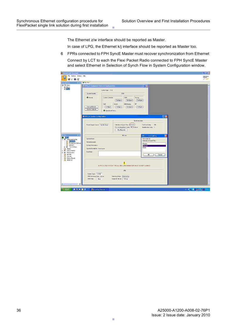
6 FPRs connected to FPH SyncE Master must recover synchronization from Ethernet
Connect by LCT to each the Flexi Packet Radio connected to FPH SyncE Master and select Ethernet in Selection of Synch Flow in System Configuration window.
.
.
A25000-A1200-A008-02-76P1Issue: 2 Issue date: January 2010
37
Solution Overview and First Installation Procedures Synchronous Ethernet configuration procedure forFlexiPacket single link solution during first installation
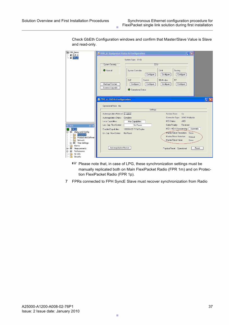
Check GbEth Configuration windows and confirm that Master/Slave Value is Slave and read-only.
☞ Please note that, in case of LPG, these synchronization settings must be manually replicated both on Main FlexiPacket Radio (FPR 1m) and on Protec-tion FlexiPacket Radio (FPR 1p).
7 FPRs connected to FPH SyncE Slave must recover synchronization from Radio
.
.38 A25000-A1200-A008-02-76P1Issue: 2 Issue date: January 2010
Solution Overview and First Installation ProceduresSynchronous Ethernet configuration procedure for FlexiPacket single link solution during first installation
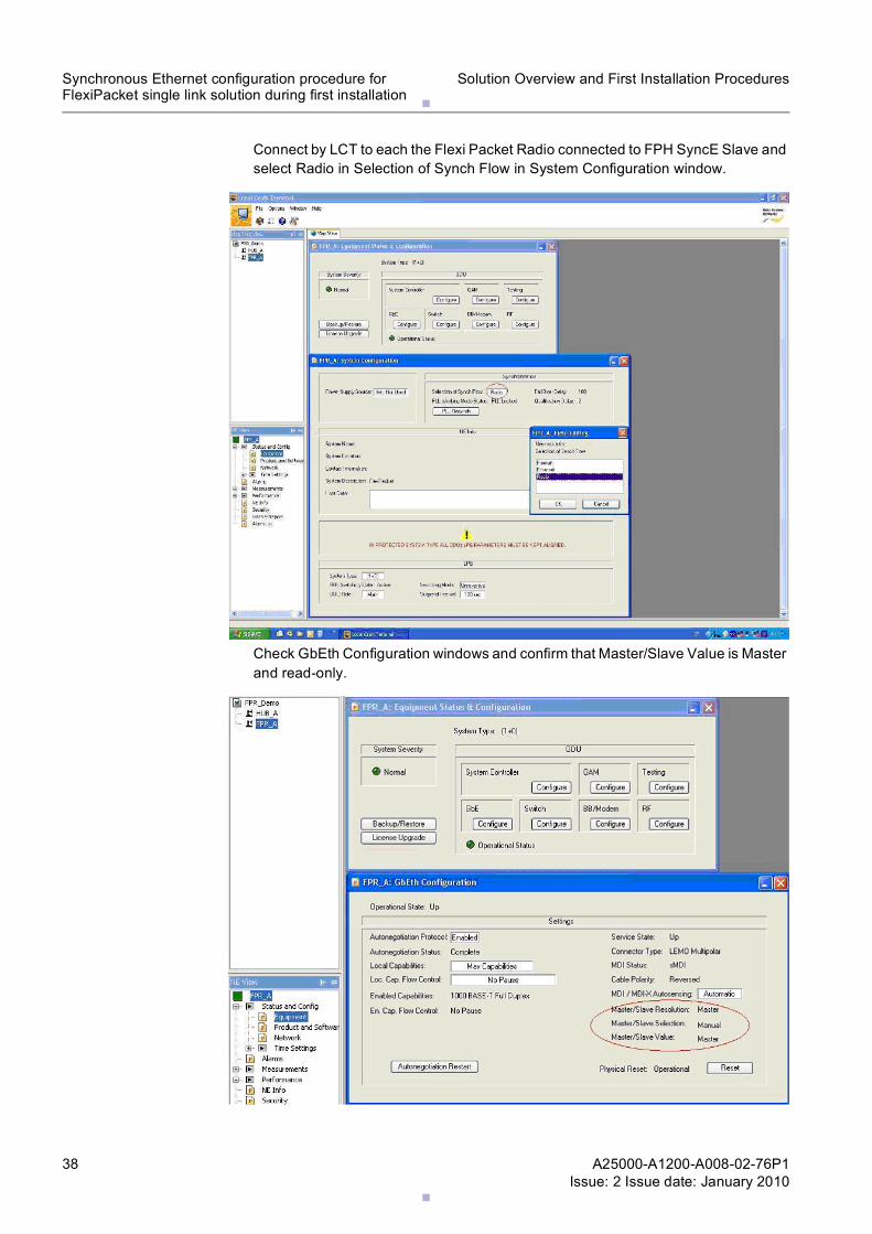
Connect by LCT to each the Flexi Packet Radio connected to FPH SyncE Slave and select Radio in Selection of Synch Flow in System Configuration window.
Check GbEth Configuration windows and confirm that Master/Slave Value is Master and read-only.
.
.
A25000-A1200-A008-02-76P1Issue: 2 Issue date: January 2010
39
Solution Overview and First Installation Procedures Synchronous Ethernet configuration procedure forFlexiPacket single link solution during first installation
☞ Please note that, in case of LPG, these synchronization settings must be manually replicated both on Main FlexiPacket Radio (FPR 2m) and on Protec-tion FlexiPacket Radio (FPR 2p).
8 Using LCT enable the Administrative State of interface x'/y', z'/w' and k'/j' (if the LPG is configured) of FPH SyncE Slave.
9 Connect by CLI to the FPH SyncE Slave by logging in with:
– username: root– password: root
10 In FPH SyncE Slave CLI execute the following commands:
– config-set ces system clock add synch-eth interface z'/w' priority 1 ssm_ql stu(selects slot z' port w', that is the Ethernet port connected to FPR as reference system clock of the FPH)
– config-set ces system clock wait_to_restore_time 60(set the wait to restore time for the reference system clock after failure recovery)
– config-set interface ethernet z'/w' ssm-state enabled(enables SSM messages on slot z' port w', that is the Ethernet port where FPR is connected to)
– config-set interface access ds1 x'/y' clock system(selects the reference system clock as the egress clock for slot x' port y', that is the CES card)
– config-set interface ethernet z'/w' clk-negotiation slave(set slot z' port w', that is the Ethernet port where FPR is connected to, as Slave for SyncE)
11 Please note that, in case of LPG, synchronization settings must be replicated also on the second port f the LPG.
In FPH SyncE Slave, also the second port of the LPG must be configured as the first one, so execute the following commands in its CLI:
– config-set ces system clock add synch-eth interface k'/j' priority 2 ssm_ql stu(selects slot k' port j', that is the Ethernet port connected to the second FPR of the LPG as reference system clock of the FPH with priority 2)
– config-set interface ethernet k'/j' ssm-state enabled(enables SSM messages on slot k' port j', that is the Ethernet port where the second FPR of the LPG is connected to)
– config-set interface ethernet k'/j' clk-negotiation slave(set slot k' port j', that is the Ethernet port where the second FPR of the LPG is connected to, as Slave for SyncE)
12 Verify that FPH SyncE Slave is correctly configured executing the following commands in its CLI:
– show ces system clock info– show interface ethernet * clk- negotiation– show interface ethernet * ssm-info
The CES system clock should be Locked on Synch-Eth z'/w', which should be Valid.
The Ethernet z'/w' interface should be reported as Slave.
In case of LPG, the Ethernet k'/j' interface should be reported as Slave too.
Related Documents