1'1 1'11111'111'11 I'll 11'111 'III 'II' II 11'11' 11'1 II 1'111' 1'1 III I I' 3 1176 00161 4719 NASA Contractor Report 163101 NASA-CR-1631 01 19810002523 A COMPUTER PROGRAM FOR CYCLIC PLASTICITY AND STRUCTURAL FATIGUE ANALYSIS I. Kalev November 1980 NOV 2 b ',S80 NI\S/\ NF02056

Welcome message from author
This document is posted to help you gain knowledge. Please leave a comment to let me know what you think about it! Share it to your friends and learn new things together.
Transcript
1'1 1'11111'111'11 I'll 11'111 'III 'II' II 11'11' 11'1 II 1'111' 1'1 III I I' 3 1176 00161 4719
NASA Contractor Report 163101 NASA-CR-1631 0 1 19810002523
A COMPUTER PROGRAM FOR CYCLIC PLASTICITY
AND STRUCTURAL FATIGUE ANALYSIS
I. Kalev
November 1980 NOV 2 b ',S80
NI\S/\
NF02056
NASA Contractor Report 163101
A COl\IPUTER PROGRAi\1 FOR CYCLIC PLASTICITY
AND STRUCTURAL FATIGUE ANALYSIS
I. Kalev
National Research Council NASA Dryden Research Associate
NI\5/\ National Aeronautics and Space Administration
1980
N til-I/O:5 /J-
~.
.. A COMPUTER PROGRAM FOR CYCLIC PLASTICITY
AND STRUCTURAL FATIGUE ANALYSIS
I. Kalev National Research Council-NASA Dryden Research Associate
Dryden Flight Research Center
INTRODUCTION
This report outlines a computerized approach for the structural analysis of the time-independent cyclic plasticity response and of the metal fatigue failure process. The approach combines three main analytical components, as follows:
(a) A cyclic plasticity model which relates the material's uniaxial stress-strain behavior to the multiaxial response of any structural component.
(b) Damage accumulation criteria which indicate both the life to crack initiation and the rate of crack growth, up to complete failure, for metallic structural components that undergo local cyclic plasticity strains. The required test parameters are derived from only the fatigue life of smooth material specimens when subjected to constant uniaxial plastic strain cycles.
(c) A finite element model for the numerical solution of the structure's nonlinear static and dynamic equilibrium equations. The isoparametric finite elements of the plane-stress, plane-strain, and axisymmetric types are incorporated. These elements are adequate for the representation of the behavior of most aircraft structural components that undergo meaningful plasticity strains.
The present combined approach enables the following types of analysis:
(a) The analysis of cyclic plasticity time-independent and rate-independent structural response under any varying loading which induces either proportional or nonproportional stress variations. Basically, the analysis is related to the material's cyclic steady-state behavior; however, the material's cyclic transient behavior can
also be approximated. The effect of the cyclic yield stress change is not included. and the material is assumed to be of the so-called Masing type. which characterizes the metallic alloys used in aircraft. In addition. the material is assumed to be initially isotropic. The effect of the material's cyclic anisotropy due to the Bauschinger phenomenon is incorporated.
(b) Crack initiation prediction under varying loadings. The prediction is made by employing the Coffin-Manson criterion for the multiaxial stress state.
(c) Crack growth rate prediction. This prediction is made by employing a novel damage criterion which relates crack growth rate to the inverse damage gradient along the crack path. The criterion accounts for (1) the effects of plasticity, (2) the effects of residual stresses and of multiaxial stress redistributions at the crack tip which lead to crack retardation, (3) the effects of multiple overloads and negative loads, and (4) the interaction of close cracks. The effect of possible crack closure is not directly incorporated; however, this phenomenon is approximated by including the effect of the residual compressive stresses at the crack tip, which is the main cause of crack closure. The effects of loading 'frequency, temperature, and other time-dependent phenomena are not incorporated.
(d) Propagated crack growth rate prediction. This prediction is based on the application of the above-mentioned damage criterion using developed damage data accumulated from several updated finite element models. No procedure for the
. inclusion of residual stresses in the propagated crack's wake is included. It is assumed that the effect of these residual stresses in the crack's wake is negligible because of their usually small magnitude and because of their accelerating relaxation rate. The orientation of the propagated crack is set either normal to the computed principal tensile stress or in a direction selected by the user upon consideration of the direction of the most damaged paths.
The computer program is an extension of the NON SAP program (ref. 1). It incorporates cyclic plasticity models and damage accumUlation criteria and has an option for sorted output. A full listing of the program's new features is given in the appendix of this report. The two-dimensional isoparametric finite elements and the numerical solution procedures are those of the NON SAP program. As this program is an in -core solver, the size of the finite element model is limited. However, the analysis of structural components is still practical by using 130K of the computer core, as demonstrated later in this report.
APPLICATION TO DAMAGE-TOLERANT AIRCRAFT DESIGNS
,
The damage tolerance requirements specified in MIL-A-83444 (USAF) (ref. 2) are , based on the assumption that a crack already exists in each element of a new structure as a result of flaws in the material, corrosion. or manufacturing damage. The struc-ture should sustain the growth of these assumed cracks without a total failure during-its lifetime, and also still sustain a specific residual static strength. Reference 2 defines two approaches for the substantiation of a structure's damage-tolerant integ-rity: the fail-safe approach and the slow-crack-growth approach. The fail-safe
2
approach assumes a smaller initial crack length and a shorter loading spectrum than the slow-crack-growth approach; however, it requires more structural accessibility for inspection and overall, as well as local, structural redundancies that are frequently impractical in aircraft structures. The slow-crack-growth approach can be applied to all structural types, and it is also simpler to implement.
The slow-crack-growth approach requires that crack growth be slow enough not to achieve an unstable size during the life of the structure. The initial crack length is .assumed to be on the order of 0 . 25 inch (6.3 millimeters) (ref. 2), and the crack is also often assumed to be through the member's thickness. These requirements can lead, under the usual applied loading, to significant plastic strains at the crack tip. A typical loading specturm is composed of varying tension-compression components, with multiple overloads, as depicted in figure 1. Although the loading variation is not of a fully cyclic type, it still often imposes cyclic plasticity stresses, because of the material Bauschinger phenomenon.
The imposed cyclic plasticity at the crack tip and the resultant residual stresses exclude the implementation of the usual analytical methods, which are based on the stress-intensity range. The present computer program can handle these phenomena analytically, by combining the finite element method, the material's cyclic plasticity model, and the damage accumulation criterion. This analysis is essential both for ensuring the integrity of the structural components during their life and for the proper evaluation of the results of structural proof tests.
The present computer program can also be applied to cases in which the crack tip undergoes relatively small cyclic plasticity strains. This application can be carried out by idealizing the material's stress-strain uniaxial curve with both a low yield stress and a first segment's slope which differs only slightly from the material's Young's modulus. However, it should be noted that the accuracy of the present damage criterion decreases for smaller plastic strains, while the accuracy of the simpler stress-intensity range approach increases. The present damage criterion is suitable only for cyclic plasticity strains; therefore, monotonically increased plastic strains as exhibited in the static residual-strength analysis cannot be handled by the present computer program. In addition, repeated loads which do not cause reverse plasticity, but cause plastic reloading at the same unloading stress, are assumed to contribute to the cumulative plastic strain but not directly to the cumulative damage. This will be clarified later in this report.
The present computer program does not account for the beneficial effects of initial compressive stresses due to shot peening, fastener interference, cold-working, and the like. However, it should be realized that these effects are usually small because of the quick stress relaxation in the cyclic plasticity field.
The required input data for the computer program are outlined later in this report.
3
THEORETICAL APPROACH
Cyclic Plasticity Models
Three plasticity models are incorporated in the present computer program. They differ from each other in their definitions of the incremental translation of the yield surfaces during the hardening of the material. The three models are identical for the proportional stress state, but they lead to somewhat different results for the usual nonproportional stress state. As none of these models has yet been shown through solid experimental evidence to be superior to the others, the choice of model is left to the user.
The three plasticity models are based on classical incremental time-independent and rate-independent plastic flow theory for initially isotropic materials. Incremental plastic flow theory assumes that the plastic strain increment is much higher than the adjacent elastic strain increment, and that plastic strain increments can be computed independently on the basis of the previous loading step stresses. Therefore, small loading step sizes, specified by the user, are mandatory for solution accuracy. The material's uniaxial stress-strain curve can be idealized by a maximum of three elastoplastic piecewise linear segments in addition to the first elastic segment, as shown in figure 2 (a). The reversal uniaxial segments are shifted by the program to twice the initial yield stress, and the length of the segments is magnified by a factor of two, assuming material of the Masing type. However, the user can change the idealization of the first reversal in order to represent the material's transient condition.
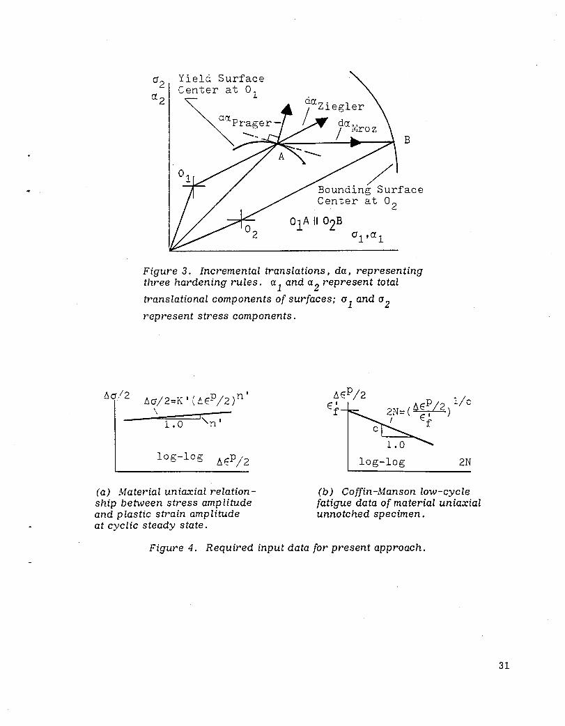
Each linear segment of the material's uniaxial curve is related to a yield surface in the multiaxial stress state, as shown in figure 2 (b). Each yield surface is defined by the von Mises criterion and the associated plastic flow normality rule. It is allowed to translate in the stress space up to its bounding yield surface, to which it remains connected until the unloading stage. The translation rate is governed by one of the following three hardening rules (fig. 3). Prager's hardening rule physically assumes that the incremental translation is in the direction of the plastic strain increment, i. e. normal to the yield surface. In order to satisfy this rule unconditionally, the surfaces' translations in the zero stress directions are mathematically permitted. Ziegler's hardening rule assumes that the incremental translation is in the direction of the vector which connects the center point of the current yield surface to the existing stress point. Both of these hardening rules require continuous position corrections of the yield surfaces to ensure tangency among the surfaces in contact. Mroz's hardening rule is based on the inherent fulfillment of this tangency requirement.
The full mathematical expressions of the plasticity models are presented in reference 3.
It should be noted that the cyclic plasticity room temperature stress relaxation phenomenon is not included in the present plasticity models; however, this phenomenon is directly included in the present damage criteria, which are discussed next.
4
Life to Crack Initiation
According to the presently used criterion, crack initiation occurs after 2N reversals of cyclic loading, when the cumulative damage D equals a unit. The damage is expressed mathematically as follows (ref. 4):
_ I2N(fdfP)-1/C( 36'm)l/n'C D- -- 1--
2ef of (1)
1
The quantity f dfP denotes the integration of the equivalent plastic strain incre
ment, dl';P, through each pair of reversals. The equivalent plastic strain increment is a positive scalar composed of the multiplication of the plastic strain increments
de? (i, j = 1, 2, 3 in tensor notation), and it is computed by the plasticity model as IJ
follows:
deP = (de? de~)1/2 (2) 1) 1]
The quantity 6' is the average value of the mean stresses at the two plastic unm
loadings which define the specific pair of reversals, or
(j = 1/2 [(a . ./3)F· tId· + (0 .. /3) S dId' ] m \ 11 Irs un oa Ing 11 econ un oa Ing (3)
The quantity 6' also represents the effects of the tensile versus compressive stresses. m
If the reversal loading results in a symmetric stress variation, or a.. = a.. ., 11 ,max 11,mln then (j = O. m
If the stress relaxation effect is to be included, as it should be when 6' is not m
small, the user must define an experimental material parameter r (ref. 3) such that the relaxed 6' value becomes
m
(4)
where a' is the original average mean stress. For the numerical examples to be m
shown later in this report, a value of r of 277 has been adopted for aluminum alloy 7075-T6 plate.
The material parameters n', c, ef' and Of in equation (1) are defined by the user
for the specific material. The parameter n' is the material's uniaxial cyclic exponent.
It relates the uniaxial stress amplitude, t:J.aI2, to the applied constant plastic strain
5
amplitude, ~EP /2, in the form of ~o/2 = K' (~EP /2)n' , where K' is assumed to be
apiJroximated by of/ (Epn'. The value of the exponent n' can be derj'len from several
uniaxial plastic strain tests at the material's cyclic steady state, as indicated by figure 4 (a). The parameter Ef is the material's cyclic ductility parameter, which is
smaller than the monotonic ductility parameter, EC The parameter of is the material's
fracture strength. The parameter c is the Coffin -;\Ianson exponent (fig. 4 (b» , which is derived from constant plastic strain amplitude tests of the material's uniaxial unnotched specimens.
The values of these material parameters depend on the specimen's surface treatment and environmental conditions. Therefore, the above-mentioned uniaxial tests have to be conducted under the same conditions as exist in the real structure.
Crack Growth Rate
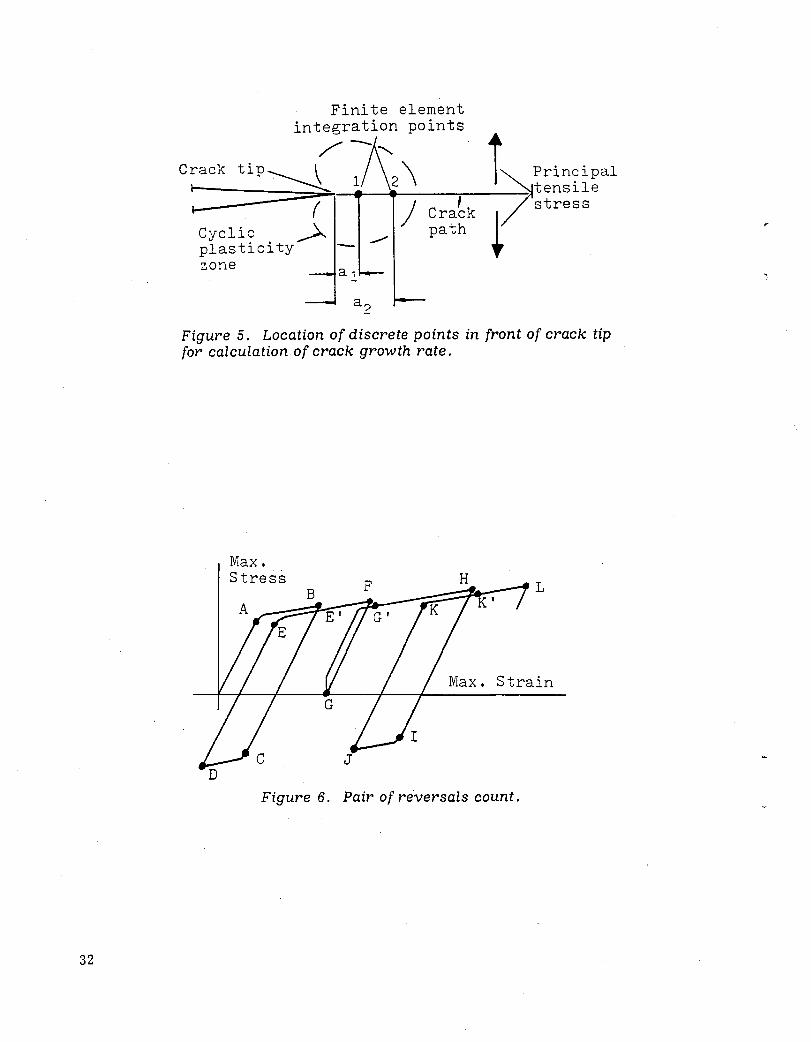
The crack growth rate is approximated by the inverse damage gradient along the crack path. The cumulative damage is computed by equation (1) at two discrete points in front of the crack tip. These discrete points are defined by the two integration points of the finite element adjacent to the crack tip. Figure 5 designates these integration points as number 1 and number 2; they are located at distances of a 1 and a 2 from the crack tip, respectively. Assume that the accumulated damage
at points 1 and 2 is termed D 1 and D2 , respectively. If the crack propagates by the
small distance of (a2 - a 1)' the damage at point 2 becomes D 1; thus, the average
cumulative damage value is 1/2 (D 1 + D2)· The crack growth rate, d ~2~~) , is approx
ima ted as follow s (ref. 3):
da d (2l~) (5 )
where a is half the length of the existing crack. Equation (5) indicates that a complete fracture occurs when D 2 ?: D 1 .
The finite element integration points, whose cumulative damage values are used for the crack g-rowth rate prediction, are chosen by the user according to the predicted crack path, which is usually normal to the direction of the principal tensile stress. These integration points should be well within the material's cyclic plasticity ro.nge. This requires a reasonably small finite element to be used at the crack tip.
Damage Accumulation Technique
The damage criterion in equation (1) is applied to each pair of reversals separately, and the results are accumulated during the entire applied loading history.
6
"
..
Each pair of reversals is defined, as mentioned before, during two subsequent plastic un loadings made in reversal directions. The plastic unloadings in figure 6, for example, occur at points B. D, F, II, J, and L. However, the unloading at point F is not eonsidered because the following plastic unloading, at point II, is not in the reversal direction. Therefore, the first pair-reversal is AB-CD, the second pail'reversal is Ell - IJ. and so on.
For tensile loads, the present pair-reversal damage accumulation technique could lead to somewhat more conservative results than the well-known rainflow technique (ref. 2). This is because the rainflow technique refers only to closed loops; in figure 6, the plastic strains along the AB, E'F, G'H branches would not be considered, because no closing counterpart branches exist. However, the rainflow technique does consider the effect of the elastic loop FGG' .
The present damage accumUlation technique does not account for the effect of elastic reversals, i. e. it ignores the effect of the elastic loop FGG' in figure 6. This is justified because the damage criterion (eq. (1)) employs the material's cyclic ductility strain 8}, which is smaller than the material's monotonic ductility strain.
The technique does incorporate the cyclic parameters n' and c; thus, it is assumed that the fatigue damage is due mainly to the plasticity cycles.
Finite Element Modeling and Equation Solutions
The NON SAP program's two-dimensional isoparametric elements and its solution procedures (ref. 1) are utilized. The eight-node element with undistorted shape and 3 X 3 integration points has been found to furnish a suitable representation of both the plastic strain variation and the damage gradient. The finite element adjacent to the crack tip should be small enough for the two integration points along the predicted crack path to be well within the cyclic plasticity range. In addition, the idealization should be such that the existing crack front is at the corner node, not at the midnode, of the eight node element. Far from the crack tip and far from the stress concentration zones, the number of nodes can be reduced to four to save computer core and time.
The behavior of large plastic strains is approximated by employing the GreenLagrange strain tensor and the second Piola-Kirchhoff stress tensor in Lagrangian coordinates. The use of this approximation is justified, since most of the fatigue failures are accompanied by only small to moderate cyclic strains around the material's yield strain.
The nonlinear equilibrium equations due to the plasticity and the large strains are solved incrementally. The size of the loading steps is variable and is set by the user, based on his numerical experience. Usually, several short trial and error runs are expected for each specific case before the largest possible step sizes are determined. The parameter which usually governs the step sizes is the material's uniaxial stress-strain slope. A smaller material slope requires a smaller step size.
The static analysis requires the construction of a new tangent stiffness matrix at each loading step. The dynamic analysis can be carried out either by employing
7
Newmark's implicit time-integration method or by employing the explicit centraldifference method. The central-difference method is much less time consuming, but it is more prone to numerical instabilities and thus requires smaller step sizes. This r:1ethod is especially attractive for cases of small material hardening, where the required time step sizes are already relatively small because of the small material slopes. The iterative NONSAP procedure for equilibrium corrections is not incorporated because of the possibility of nonconvergence at the plastic unloading steps.
PROGRAl\I OUTLINE
The program utilizes the NONSAP computer program's elements and solution techniques for large strains and plasticity, and for static or dynamic analysis. The new features presented here include the following:
(a) The incorporation of the cyclic plasticity models and fatigue data computations throug'h a separate overlay (number 3.8; see appendix). The NON SAP overlay tree is shown in reference 1.
(b) Sorted output data. This is necessary because of the enormous available output data and the need to segregate the fatigue data required for the computation of the damage criteria.
Following is a brief summary of the main computation steps.
(a) The overall linear stiffness and mass matrices are constructed first. If dynamic analysis is required and Newmark's direct time integration technique is used. the overall linear effective stiffness matrix is constructed. In addition, the applied load vector is constructed. The large strain stiffnesses derived by using the Total Lagrangian procedure and the cyclic plasticity stiffnesses are updated at each loading or time step. These ·stiffness values are added to the linear stiffness matrix.
(b) The equilibrium equations are solved incrementally, and displacements and strains are obtained for each step. The program has an optional two-step restart capability, which is useful for problems which involve only partially different loads and for dividing a long computer run into two separate and more manageable runs.
(c) For each finite element integration point which is pre-defined by the user as an elastoplastic element, the following steps are executed at each loading or time step.
• The previous step's values of elastoplastic stiffness are recomputed.
• The plastic strain increment is computed, as is the total equivalent plastic strain.
• The stress increment is computed and the total stresses are updated. The mean stress is computed.
• The yield surface translations are computed, ensuring that the surfaces' nonintersection requirement is met.
8
-The elastoplastic stiffnesses are updated in four subincrements and added to the overall structural stiffnesses for the next loading step.
-Continuous checks are made for plastic unloading. If it occurs, the peak von l\1ises stress is kept in the memory to indicate the following reloading state.
-Plastic loading or reloading is considered when the current stress point reaches the first yield surface. The plastic reloading criterion distinguishes between reyielding at the reversed plastic region and reyielding at the same plastic region. Reyielding at the same plastic region is initiated when the accumulated elastic work during the unloading range is zero, or nearly zero. The computed accumulated damage value is for each pair of reversals; only fully reversed stress cycles are considered.
-The fatigue data for equation (1) are computed. After each pair of reversals, damage is accumulated for an indication of the life to crack initiation. The crack growth rate is computed by substituting the results of equation (1) into equation (5).
The mathematical formulations are presented in reference 3.
INPUT AND OUTPUT DATA
The input data are identical to the NONSAP specifications, with the following exceptions. The specified material model number for the cyclic plasticity analysis is NPAR(15) = 9. The number of constants per property set should be specified as NPAR (17) = 15, and the dimension of the storage array should be specified as NPAR(18) = 27. Then the material properties are specified on two input cards. The first input card contains eight parameters, in 8F10. 0 format, as follows: the Young's modulus, the Poisson ratio, the yield stress, and the uniaxial slope of the first elastop las tic piecewise linear segment; the yield stress and the uniaxial slope of the second segment; and the yield stress and the uniaxial slope of the third segment. The second input card contains seven parameters, in 7FIO. 0 format, as follows: the yield stress and the uniaxial slope of the first, second, and third plastic reversal segments; and a seventh parameter, RULE, that indicates the required cyclic plasticity model. If RULE = 0, rigid plastic material is assumed. If RULE = 1, the well-known isotropic hardening rule is employed. If RULE = 2, 3, or 4, the kinematic hardening rule due to Prager, Ziegler, or Mroz is used, respectively.
For a material in the cyclic steady state, the specified reversed yield stresses and slopes should be identical to the values of the first reversal. Different slopes can be specified for the first and second reversals for representation of the material's transient state. In the following reversals the data specified for the second reversal are used.
The output data are printed on four tapes: TAPE6, TAPE12 , TAPE13, and TAPE14. TAPE6 includes the input data and deflections. TAPE12 includes parameters for fatigue analysis. Included are the following terms:
9
NEL - The finite element number. IPT - The integration point number. LO - The number of plastic reversals. For the iirst plastic range LO = 1, for the
second plastic reversal LO = 2, and so on. IPEL - The current position of the equivalent von Mises stress. If IPEL = 1, 2, or
3. the stress point is on the first, second, or third piecewise linear segment. respectively.
DEPC - The cumulative equivalent plastic strain. S:\IEAN - The mean stress. FT - The equivalent von i\Iises stress. SX - The maximum principal stress. SY - The minimum principal stress. ALPHA - The direction of the maximum principal stress relative to the element's
coordinates. I
DWE - ~umerical stability indicator. It equals the stress increment times the elastic strain increment. The value should be positive; otherwise it indicates that a numerical instability due to too high step size has been introduced.
HP - Numerical stability indicator. It should be equal to the input slope of the specific material segment.
WP - Unloading indicator. If WP is negative, unloading occurs. IRE - Reloading indicator. If IRE = 0, there is no reloading. If IRE = 1 or
IRE' = 3, fully reversal plastic reloading occurs. If IRE = 2, plastic reloading occurs at the same unloading point.
WP2 - The cumulative plastic work. Used for reference. DEE - The current total work. Used for reference.
TAPE13 includes the computed stresses. TAPE14 includes the computed strains, surface translations, and other parameters explained in the printout shown in the appendix of this report.
The output data from TAPE12 are used for the fatigue analysis. The other data uSed in the fatigue analysis include the material's cyclic stress-plastic strain exponent n' and the Coffin-:'Ianson material parameters c, 8r, af
, which are defined in
equation (1) . .-\lso needed is the material stress-relaxation exponent r, which is
defined in equation (4). The f d8P value in equation (1) is calculated by subtracting the comput2d DEPC values at the two plastic unloading points which define the specific pair of reversals. The average of the Si\IEAN values at these two unloading points is calculated according to equation (3). This value should be iteratively reduced by employing equation (4) because of the assumed cyclic plasticity stress relaxation. Then equation (1) is employed for the accumulation of the pair-reversal damage. When it reaches a unit value, crack initiation is assumed. The crack growth rate is approximated using equation (5) by substituting the cumulative damag-e values at the two discrete points in front of the crack tip and along the predicted crack' path. The crack growth path is usually predicted to be normal to the direction of the principal tensile stress, which is indicated by the ALPHA value.
, 10
'.
..
APPLICATION EXAMPLES
This section describes the application of the present approach to the analysis of two structural components: a cracked panel under variable uniaxial loadings und stiffened aircraft skin panel under compressive loading.
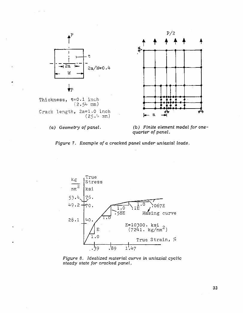
The cracked panel is shown in figure 7 (a). The magnitude of the applied loadings is such that significant plastic strains develop in front of the crack tip. Figure 7 (b) depicts the finite element model, which employs plane-stress four-to-eight node isoparametric elements. The eighth node elements are solved by 3 X 3 integration points. The uniaxial cyclic material curve, idealized by three piecewise linear segments, is shown in figure 8. The material's fatig-u.e properties are based on the constant strain amplitude test data from reference 5. The fatigue ductility parameter, ef, is assumed to be 0.18, while the measured monotonic ductility, e
f, is 0.41. The
fatigue strength, af' is assumed to be equal to the monotonic fracture strength, af' or
75.9 kg/mm 2 (108.0 ksi). The Coffin-Manson exponent c in equation (1) is estimated to be 0.52. The material uniaxial cyclic exponent, n' , is 0.1 L
In order to account for the stress relaxation, a value of I' of 277 is assumed in equation (4). This value causes the relaxation of the existing mean stress down to 0.01 percent of its initially computed value, within two fully reversed strain cycles of o . lei- .. No experimental evidence exists for this value.
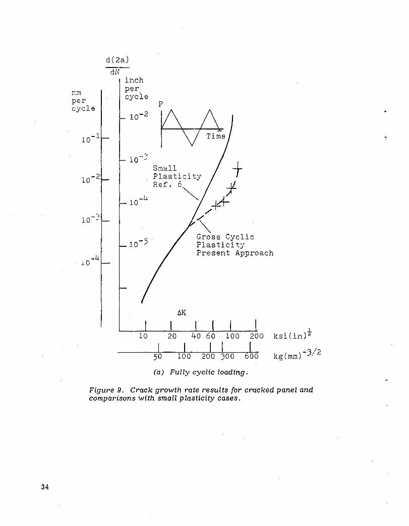
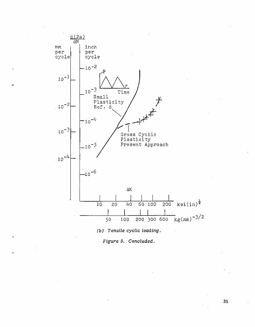
Results for fully cyclic loading and for tensile cyclic loading are shown in figures 9 (a) and 9 (b) and compared to test results which induce only small plasticity . These comparisons illustrate the significant crack growth retardation due to the plasticity stress redistributions and due to the residual compressive stresses developed after plastic unloading. The relative crack growth retardation is more significant for the tensile cyclic loading (fig. 9 (b» than for the fully cyclic loading (fig. 9 (a». This is because the residual compressive stresses in the latter case are followed by residual tensile stresses which diminish their beneficial effects. The computed crack displacements indicate that no crack closure occurs for the present
loading conditions. The crack growth rate, d ~~a) , in figures 9 (a) and 9 (b) is
depicted as a function of the stress intensity range AK = ~ • Aa • va, where ~ is a geo-n
metric parameter, Aan is the net section stress range, and a.is the half crack length.
For cases of small and localized plasticity, the stress-intensity range is generally a representative parameter. However, in cases of gross plasticity, as in the present examples, ilK loses its general validity; thus, the results shown in figures 9 (a) and 9 (b) are specific for the crack length used.
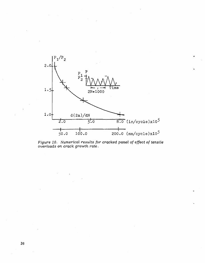
Figure 10 shows the effect of a tensile overload on the crack growth rate as computed by the present approach. It is apparent that this effect becomes more significant with increasing values of overload. This is in general agreement with the test data that have been reported in the literature.
11
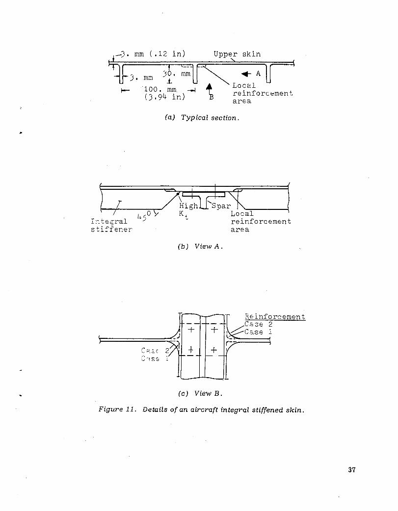
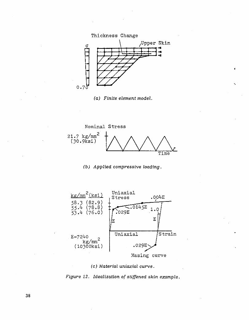
The stiffened skin panel is shown in figure 11. The integral stiffeners' cross section at the spar location is changed as shown in figure 11 (b). Axial loads due to overall wing bending could lead to high stress concentrations at the indicated point. These stress concentrations can usually be significantly reduced by the addition of a small area of structural reinforcement. Two cases, with different reinforcement area sizes, are analyzed. They are designated case 1 and case 2. Figure 12 (a) shows the finite element model used. The applied loads are compression and vary with the stiffener's depth, as shown. The applied loading variation, shown in figure 12 (b) , causes local compressive yielding and high residual tensile stresses after unloading. Thus, although no tensile loads are applied, a cyclic compression-tension stress-strain ~ field exists, causing crack initiation and propagation. The material's uniaxial stressstrain curve is idealized by three linear segments, as shown in figure 12 (c). The material':3 fatigue properties are the same as those indicated for the cracked panel in the p.L'evious example.
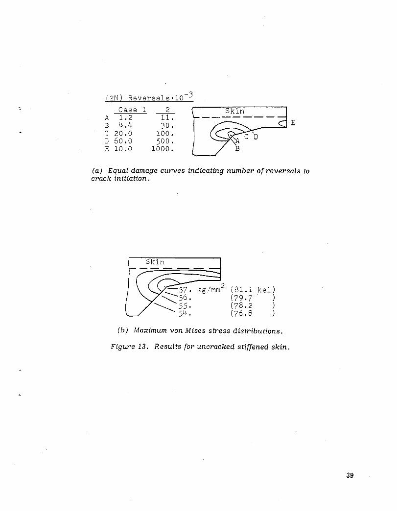
Figure 13 (a) shows the computed damage curves. Each curve indicates the equal damage accumulation value. As depicted, the small reinforcement area in case 2 significantly improves the life to crack initiation. Figure 13 (b) shows the von i.\Iises equivalent stress distribution for case 1. It is apparent that the stress gradient is much smoother than the damage gradient. This demonstrates the inability of stresses to predict the fatigue failure in a plastic field.
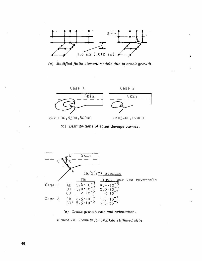
Figure 14 (a) shows examples of the used cracked finite element models. The lefthand model represents the initial crack pattern, which is perpendicular to the component's free edge (and to the direction of the principal tensile stress). However, in order to maintain the element's parallelogram shape, which is an important factor for numerical accuracy, the crack's direction is changed slightly, as shown. The righthand model in figure 14(a) represents progressive crack growth. The damage curves before the crack changes its direction are shown in figure 14 (b). The damage accumulation gradient and the crack growth rate are derived from the curves shown in figures 13(a) and 14(b). The results are summarized in figure 14(c).
CONCLUDING REMARKS
This paper describes a computerized approach to the calculation of cyclic plasticity structural response, the prediction of life to crack initiation, and the prediction of cruck growth rate. The method uses three analytical items: the finite element method and its associated numerical techniques for nonlinear static and dynamic analysis, the material cyclic plasticity theory, and the cumulative damage criteria.
The required input data include the loading spectrum, the material's cyclic uniaxial stress-strain curve, the ma.terial's cyclic stress-plastic strain exponent, and the Coffin -i.\Ianson low-cycle fatig'ue parameters. These parameters are derived from only smooth uniaxial specimens. The method also requires the material's stress relaxation exponent.
12

..
The damage criteria, and to some extent the cyclic plasticity models, are novel and without sound experimental supporting evidence. However, it is believed that in combination with engineering judgment, they can be used to obtain useful qualitative results.
The present in-core computer program is limited to small structural components. Provision for out-of-core computations would permit much broader application .
13
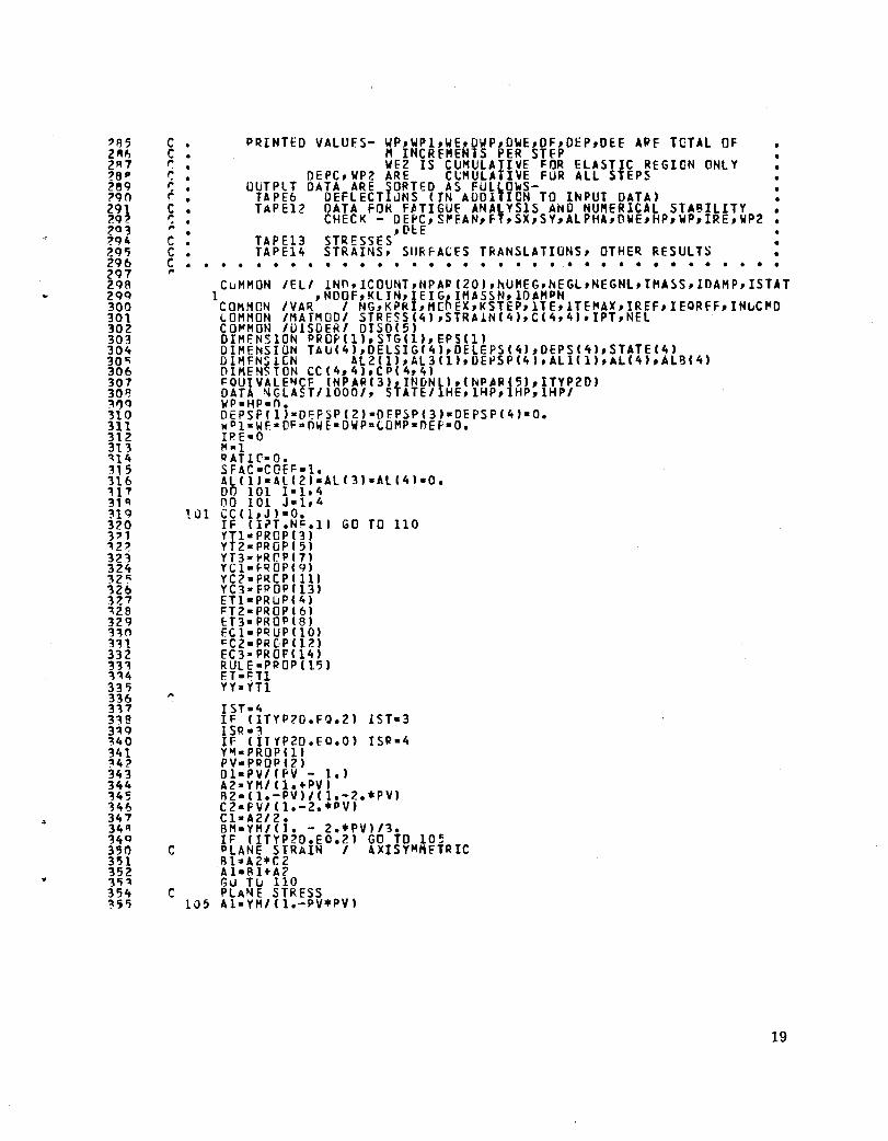
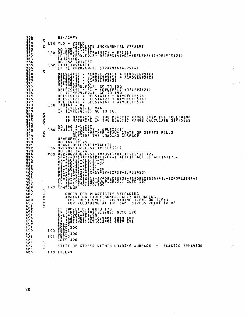
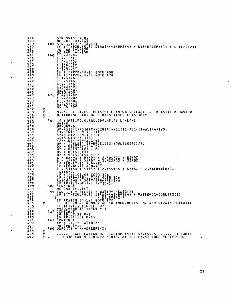
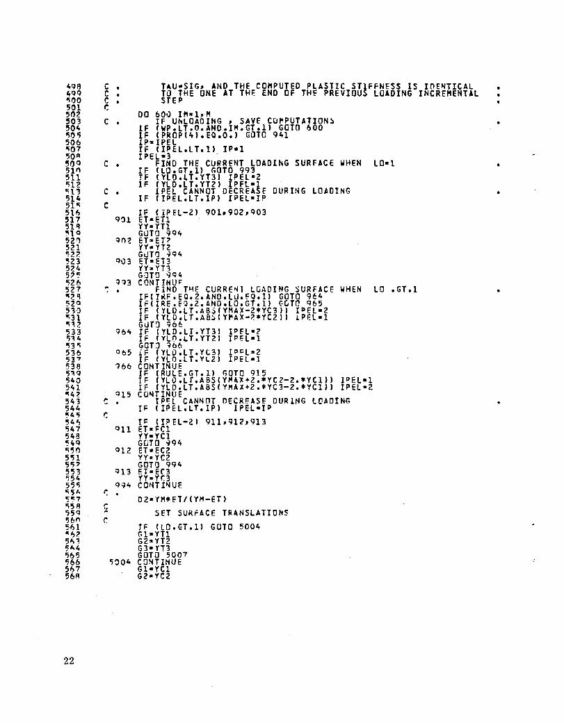
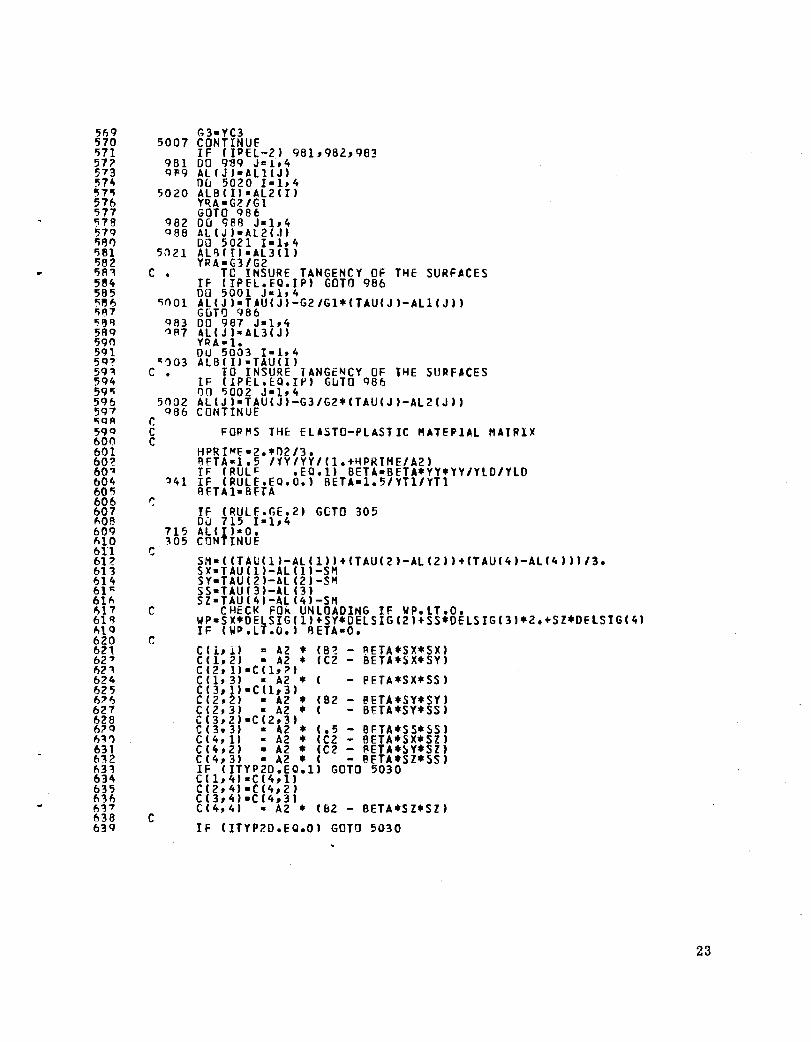
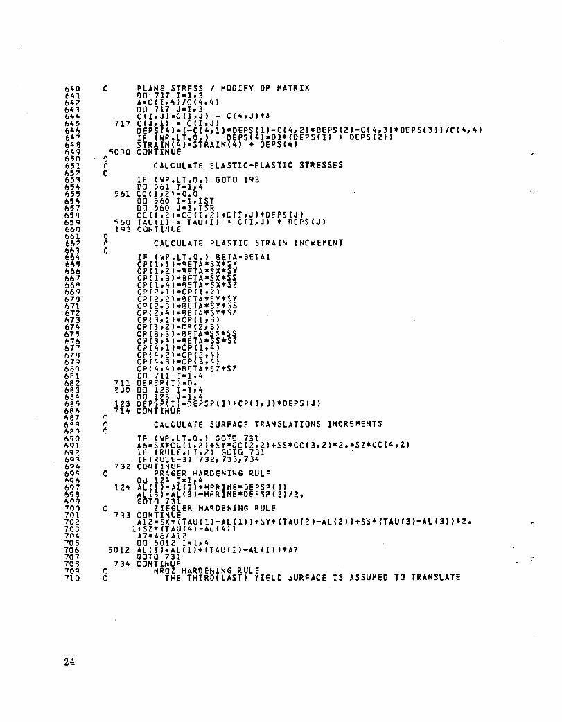
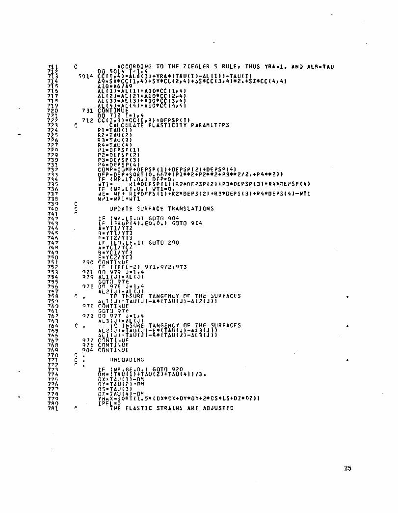
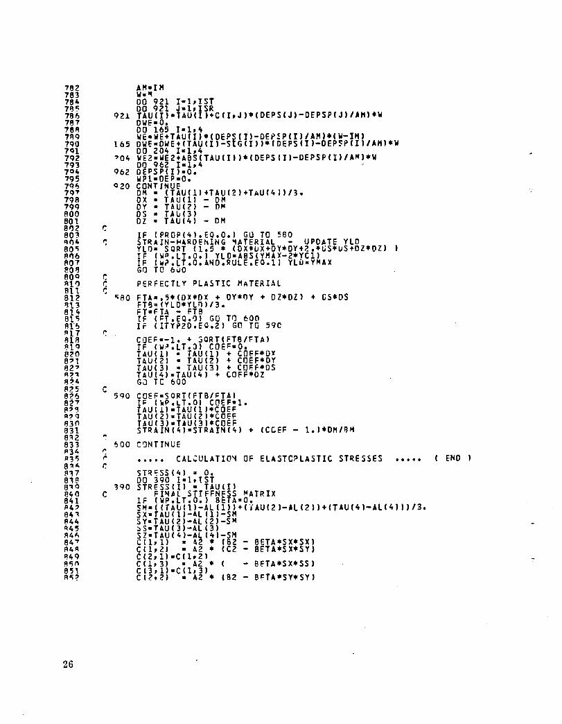
APPENDIX-PROGRAM LISTINGS
Following is a listing of the program CYCLIC for cyclic plasticity and fatigue analysis. The program includes the modifications to the NON SAP computer program (ref. 1) and the new overlay (number 3.8) .
Explanatory titles and descriptions of the variables used are incorporated within the listing.
14
I '1 4 0;
" 7 FI 9
10 11 12 , '::I
i4 1'; 16 17 1'\ 11) 20 ?1 n ?'3 24 ?';
26 27 ?F\ 'Q 31) 31 H 3" 34 '::1'5 3'> '::17 38 39 41) 41 4, 4'\ 44 4'5 4~ 47 4Q 4Q r:1)
51 0;' 0:;'3 "4 5'" 56 57 o:;~
'5Q b'l 61 62 6':1 64 "'5 6~ 67 "q I,Q 70 71
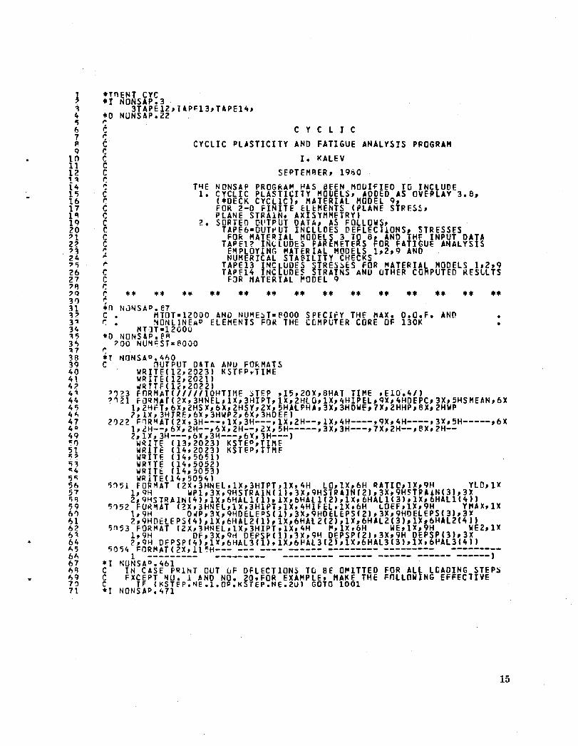
*TnE~T cye .1 NONSAP.3
3TAPE12,lAP~13,TAPEI4, *0 NUNSAP.22 ,. fo ~ C C C c e r, ,. c r, c c c c g ,. ,:.
•• •• • •
CYCLIC
CYCLIC PLASTICITY AND FATIGUE ANALYSIS PPOGRAM
I. KALEV SEPTEHRER, 19130
T~E NONSAP PROGRAM ~AS BEEN MODIfIED TG INCLUDE 1. CYCLIC PLASTICITY MODELS, ADDEO AS OVEPLAY 3.8,
(.OECK CYCLIC), MATERIAL HODEL 9, FOR 2-0 FINITE cLEMENTS (PLANE STRFS~, PLANE STRA1N, AXISYHMETRY)
2. SORTEO OUTPUT DATA, AS FOLLOWS, TAPE6·0UT~UT INCLlDES ~EFLEC1!ONSl STRESSES
FOR MATERIAL MODELS 3 TO 8, AND lHF INPUT DATA TAPE1? IN~LUDES PAREHETERS FOR FATIGUE ANALYSIS
EMPLOYING MATERIAL MODELS 1,2,9 AND NUMERICAL STABILITY CHECKS
TAPE13 INCLUDES ~TRES~ES fOR MATERIAL MODELS 1,2,9 TAPE14 JNCLUDE~ ~TRAINS AND uTHER COMPUTED RESLLTS
F3R MATERIAL ~ODEL 9
• * • * * ... * • *. • * * • •• •• •• .*
15
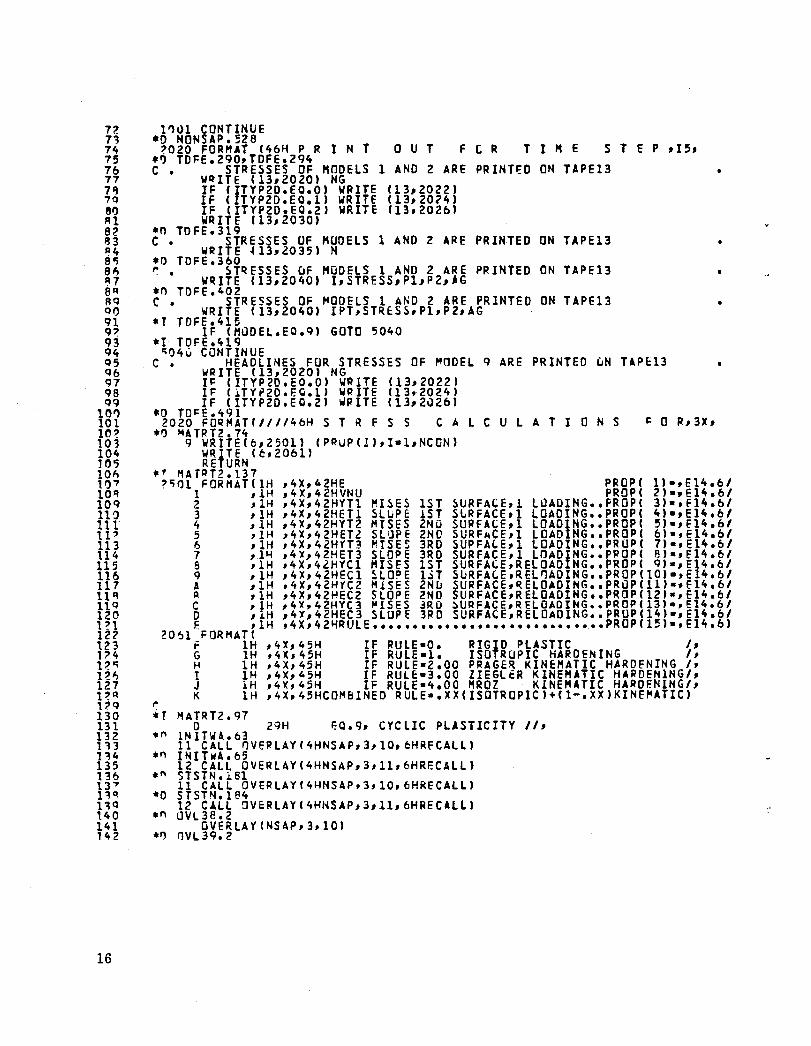
n 71 74 75 76 77 711 7Q 81) Rl 82 ~3 ~4 80; 8" A7 8~ AQ 01) 91 9~ 93 94 Q5 Qb 97 98 QQ
10" 101 lO~ 103 104 10'; 101, 1,,7 10" 10Q na 111 11' 113 114 115 116 117 11" llQ 120 PI 1Z? t23 1'4 V'i HI, 127 p~
1"Q 130 131 132 1'B n4 135 B6 13" 1~~ no 1.40 141 142
16
11)1>1 CONTINUE .0 HONSAP.!;Z8
2020 FORHAT (46~ P R I N T *ry TOFE.290,TOFE.Z94
OUT feR T I '" E S T E P ,15,
C • STRESSES OF MODELS 1 AND 2 ARE PRINTED ON TAPE13 WQITE (13,2020' NG IF (ITYP2o.EO.0' WRITE (13,2022' IF ( TYPZo.EO.l' WRITE (13,2024' IF (ITYP2D.EQ.2' WRITE (13,ZOZb' WRITE (13,2030'
*0 ToFE.319 C • STRESSES UF MUoELS 1 AND 2 ARE PRINTED ON TAPEl3
W~ITE ~13,2035' N .0 TOFE.360 ~ • STQESSES uF MODELS 1 AND Z ARE PRINTED ON TAPE13
W~ITE (13,2040) I,STRESS,Pl,P2,_G .0 TDH. 40Z C • STRESSES OF MODELS 1 AND 2 ARE PRINTED ON TAPE13
WRITE (13,2040) IPT,STRtSS,Pl,PZ,AG *y TDFE.415
IF (HODEL.EO.q, GOTO 5040 .1 TDFE.419
'i04V CONTINUE C • HEADLINES FOR STRESSES OF ~ODEL Q ARE PRINTED wN TAPE13
WRITE (13,2020' NG IF (ITYP2D.EO.0' WOITE (13,2022' IF CiTYP20.E'.1) WRITE (13r2024, IF (ITYP2D.EQ.Z' \If/ITE (13,21l2b'
*0 TO~E.491 CAL C U L A T ION S 2020 FORMATCIII146H S T R F. S S
*1) '4A TR T2 • 74 Q WRITE(6,2501' (PRUP(!),I-l,NCON'
WRfTE (e. 20bU RE URN
•
•
*' MATRT2.137 ?'i()l FoRIUTI IH ,4X,4ZHE PROP( 1'·,E14.61
,4X,42HVNU PROP( 2)-,E1~.61
,.
1 ,.lH 2 ,1H 3 ,IH 4 ,1H 5 rlH 6 ,lH 7 ,1~ 8 IlH Q ,1H A ,1H II ,1H C ,1H o ,1H E dH
,4X,42HYT1 ~I~E~ 1ST ~URFACE,1 LOADING •• FROP( 31·,f14.bl ,4X,42HET1 ~LuPE 1ST SLRFACE,l LOADING •• PROP( 4)-,E14.61 ,4X,42HYT2 MISES 2ND SURFACE,l LOADING •• PROP( S'·,f14.61 ,4X,42HET2 SLaPE 2ND SURFACE,l LOAoING •• PROP( 6'·,E14.bl ,4X,42HYT~ MISE$ 3RO SUPFA~E,l LOAoING •• PRUP( 7)·,E14.61 ,4X,42HET3 SLOPE 3RD SURFACE,l LOADIHG •• PPOP( 8)-,f14.61 ,4X,42HYCl HISES 1ST SURFA'E,RElOAD NG •• PROP( 9,·,E14.61 ,4X,42HECl ~LO~E l~T SURFA~E,RElnAOING •• pRap(10)-,E14.bl ,4X,42HYC2 H1SES 2Nu SURFACE,~ELOADING •• PROP(ll)-,E14.61 ,4X,42HEC2 SLOPE 2ND SURFACE,RElOAOIHG •• PROP(121·,E14.61 ,4X,42HYC3 ~lSES 3RO ~URFACE,RELOAOING •• PROP(13).,E14.61 ,4X,42HEC3 SLOPE 3RD SURFACE,RELOADIHG •• PRUPC141-,E14.61 ,4X,42~RULE ••••••••••••••••••••••••••••• PROP(15)-,E14.bl
2061 FOR M AT ( F IH ,4X,45H IF RULE-O. RIGID PLASTIC I,
,4X,45H IF RULE-l. ISOTROPIC HARDENING I, G 1H H 1H ! IH J 1H K IH
,4X,45H IF RULE-Z.OO PRAGER KINEMATIC HARDENING I, ,4X,45H IF RUlE-3.00 ZIEGLER KINEMATIC HARDENlNG/, ,4X,45H IF RULE-4.00 HROZ KINEMATIC HARDENINGI, ,4X,45HCOMBINED RUlE·.XX(ISOTROPIC'+(l-.XX)KINE~ATICI
.r I1ATRTZ.Q7 o Z9H ~Q.9, CYCLIC PLASTICITY II,
." lNlTWA.63 11 CALL nVERLAYC4HNSAP,3,10,6HRfCALL'
.,., INIhA.65 12 CALL OVERLAY(4HHSAP,3,ll,6HRECALl'
*" STSTN.j,Bl 11 CALL OVERLAyr4HNSAP,3,lO,6HRECAlLI "'0 STSTNol84
12 CALL aVERLAY(4HHSAP,3,11,6HRECAlLI .n LlVL38.2 QVERLAYCNSAP,3,10'
.1) IJVL 39.2
14~ lit 4 145 146 147 148 140 15') 151 157 10;" 154 150; 15" 157 1 a; R 1";9 11,,, ,1,1 '67 16~ 1M 165 l6~ 1fl7 1f1R 1"9 170 171 '7' Hi 174 175 17~ 177 17'l 179
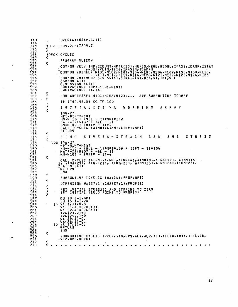
1R
" un III? 1R3 HI, 1 II c:; 186 1~7 l!3 R }l'9 19') 101 n? I'B 194 19" '1~ 107 lOR 1 0 9 201"1 201 7"? ?O'l 2')4 200; 21)6 2,,7 20B 209 ?10 ?ll 712 21 ":\
OVERLAYINSAP,3,111 C *0 ELT2D9.2,ELT?09.7 ~ ,. *I)~CK CYCLIC C
C
c C r.
fOR AODRFSSES NI01,NI02,NI03, ••• SEE ~UBROUTINE TCDHFE IF IT~O.~E.O) GO Tn 100
c ,. 1 N r T J A LIZ E W A W 0 R KIN G A R R ~ Y c
,. ,. to r N f' S T Q F. S S - S T ~ A 1 N l A ~ AND S T RES S C
c
r. C C ,.
r
100 IF'\I/- 27 Nn"NiNT*NINT NN-~110 + IN~L - 1)*NPT.1D~ + I1PT - l'*IDW MATP-IAIN107 + ~EL - I' NM"~109 + I~ATP - 1).4 CALL CYCLIC (AINM),A(NN),AINh+4),A(NN+8',A(NN+12), A(NN+lb)
1, '(N~+2~), A(NN+21), A(NN+22), AINN+23),A(NN+24),A(NN+25), 2 A(NN+2t:1I RETIIP~ END SU8ROUTiNE ICyr.LIC (WA,IWA,PPGP,NPT)
urMENSION WA(27,1),lWA(27,1"PROP(1)
SET ~NITIAL STRES~ES AND STRAINS TO ZERO SET INITIAL YIELD POINT TO PROP(')
Ow 10 J-l,NPT LlJ 15 I-l,2u
15 WAII,J)-O.O WAI2l,Jl-PQOP(3) WA(?2,J)-P~uP(3) IWA( 23, J):sO tWA(24,J)·O WAI25,J)·0. WAI 26,·J )·0.
10 IIAIZ7.J)·O. RHURN END
SUBROUTINE CYCLIC lWEZ,WP2,DEPC)
C • • • • • • • • • • • • • • • • • • • • • • • • • • • • • • • • • • •
17
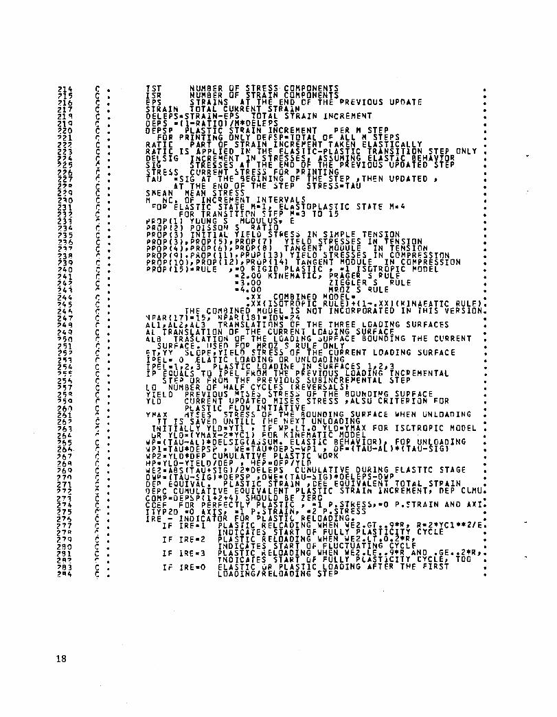
18
c • C • C • C • C • C • C • r: • c • C • ~ c • r: • c • C C • r; • c • to
r. : c • c • c • ,. . . s · '. . r. • c • to
r: • c • I": • C • r • C • r: • r: • c • r • C • C • r; • c • c • r C • ~ . ,. .. . to . . ,. c • r: • r; • r. • c • c • ,. '- . ,. c : c • r' C • c • ,. c • C • C • ,. . . C • C •
1ST NUMBER OF STRESS COMPONENTS ISR NUMBER OF STRAIN COMPONENTS EPS STPAINS AT THE END CF THE PREVIOUS UPDATE STRAIN TOTAL CUkRENT STRAIH OELEPS-STRAIN-EPS TOTAL STRAIN INCREME~T OEPS -(l-RATIO'/H*OELEPS OEPSP PLASTIC ST~AIN IHCREMENT PER M STEP
FOP PRINTING ONLY DEFSP-TOTll O~ ALL M STEPS RATIC PART OF STRAIN INCP.E~ENT TAKEN ELASTICALLY
• • • • •
RATIe IS APPLIED I~ THE ELASTIC-PLASTIC TRANSITION STEP ONLY. OElSIG INCRE~ENT IN STPESSESt AS~UHING ELASTiC BEHAvrOR SIG STRESSES AT THE END Or THE PREVIOUS UPOATEO STEP STRE~S CURRENT ~TRESS FOR PRINTING TAU -SIG AT THE ~EGINING OF THE STEP ,THEN UPDATED,
AT THE END OF THE ~TEP STPESS-TAU SMEAN MEAN STRESS M NC. OF LNCqEMENT INTERVALS ~OP ELASTIC STATE H-1, ELASTOPLASTIC ST.TE M-4
FOR TRANSITIrN ~TF.P ~-3 TO 15 ~~1P(1) YUUNG S MLDULUS. E ~RaP(2) POlSS0~ S RATIO PPOP(3) INITIAL YIELu ST~ES~ IN SIMPLE TENSION ~ROP(3),PROP(5),PROPC7) YIELD STPESSES IN TENSION PPOP(4),PROPCb),P~OPC8) T~NGENT MOUULE IN TENSION PROPCQ),PKOPClll,PPUPC13) YIELD ST~ESSES IN COMPRESSION PROPCIOI,PROPCIZ),PRuP(14) TANGENT MODULE IN CO~PRESSION PROPfI5)-PULE ,-0 ~IGIO PLASTIC, -1 ISOTROPIC ~OOEL
s2.00 KINEMATIC, P~AGER S PULE -3.00 ZIEGLER S RULE -4.00 H~OZ S qULE
• •
• • •
.XX COHBINED "ODEL- •
.XXCI~OTROfIC RUlE)+C1-.XX)C~INAEATIC RULF.). fHE COM~INED MUDEL IS NOT INCORPORATED IN THIS VERSION.
~PAR(17)-15, ~PARC18l-IDW-?4 • AL1,Al2,Al3 TRANSLATInNS OF THE THREE LOADING SURFACES AL TRANSLATION OF THE CURRENT LOAuING SURFACE 416 TRASLATION OF THE LOAD1NG ~UPFACE BOUNDING THE CURRENT
SURFACE. "SEn FOP HROZ S RULE ONLY ~T,YY SLOPE,YIEL~ STRESS OF THE CURRENT LOADING SURFACE IPEL- 0 flATIC LOADING OR UNLOADING IPEL-l,2J3 PLASTIC lOAOI~E IN 5uRFACES 1,2,3 IP ECUALS TO IPEL FROM THE P~EVIOUS LOADING INCPEHENTAL
STE~ UR FKOM THF PREVIOLS SUBINCRE~ENTAL STEP LO NUMBER OF HALF CYCLES (REVER~ALS) YIELD PREVIOUS MI~E~ ~TRES~ OF THE BaU~CING SUPFACE
• YLO CURRE~T UPOATED HISES STRESS ,ALSU CRITEPIaN FOR PLAST1C ~LOW I~TIATIVE
Y~AX ~T!ES STRESS OF T~E ROUNDING SURFACE WHEN UNLOAOING • TT IS SAVEO U~TILL THE NEXT UNLOADING
INITIALLY YLO-YTI , IF WP.LT.O YLD-YMAX FO~ IStTROPIC MODEL GR YLO-CYMAX-2*YC1) ~OR KINEMATIC MODEL wP-CTAU-Al)*DELSIGCA~SUH. ELASTIC BEHAVIOR), FOP UNLOADING WPI-TAU*DEPSP , WE-TAU*DEPS-WP1 , DF-CTAU-AL)*CTAU-SIGl WP22YLD.D~P CUMULATIVE PLASTIC WOPK HP-YLD-YIElO/OEP , ~E?aOFP/YLn ~E~-ABS(T4U+SIG)/2*DELEPS C~MULATIVE DURING FlASTTC STAGE DWP.(TAU-SIG).DEPSP ,OWE-CTAU-~IG)*OELEPS-OWP • DEP EQUIVAL. PLASTIC STRA1N ,eEE EQUIVALENT TOTAL STPAIN • OEPC CU~ULATIVE EOUIVALENT PLASTIC STRAI~ INCREMENT, OEP CLMU. COHP-OEP~P(1+2+4) SHOULD BE ZERO • COEF FOR PERFECTLY PLASTIC, -1 P.STRES~,·O P.~TRAIN AND AXI. ITYP2D -0 AXIS, -1 P.STRAIN, -2 P.STRESS • IRE - INDICATOR FUR PLASTI~ ~ELOADING. •
IF IRE-1 PLASTIC RELCADING WHEN WE2.GT •• 9*R, R-Z*YC1 •• Z/E. INDICATES START Of FULLY PLASTICITY CYCLE
IF IRE-2 PLASTIC RELOADING wHEN WE2.LT.O.Z*R, • I~DICATES START OF FLUCTUATING CYCLF •
IF lQE-3 PLASTIC KELOADING WHEN WEZ.LE •• 9*R AND .GE •• Z*R,. TNDICAfES STA~T uf FULLY PLASTiCITY CYCLE, TOO
IF IRE-O ELASTIC UP PLASTIC LOADING AFTER THE FIRST LOADING/RELOADING STEP
~fl5
Z"" ZR7 ?8 P
Ze9 ?90 29l ?9 _ ?o'3 ?94 29'; 296 297 298 299 300 301 30Z 303 304 30" 306 307 3013 ,,,Q '310 311 312 313 114 315 '316 317 31 R ~1 9 3Z0 3~1 1Z? 323 324 nr:; 3Z6 327 1Z8 329 331' 331 332 '331 314 33 '; 336 337 31B 319 140 341 ;:l4? 343 344 345 '\46 347 34R 349 350 3'51 '352 30;1 354 ~;';
C • C • r: r: • r: • ('
C • ,. . . ,. C C • C • ,.
PRINTED VALUES- WP,WP1,WE~OWP,DWE,DF,DEP,OEE APf TOTAL OF " INCRfMENTS PER STEP WEZ IS CUMULATIVE FOR ELASTIC REGION ONLY
DEPC,WP2 ARE C~HULATIVE FUR ALL STEPS OUTPlT DATA ARE SORTeD AS FUlLOWS-
TAPE6 DEFlECTIJNS (TN ADDITION TO I~PUT DATA)
•
• •
TAPE1Z DATA FOR F~TIGUf ANALYSlS AND NUHERICAl STA8ILITY • CHECK - DE~C,S~EAN,fT,SX,SY,AlPHA,OWE,HP,WP,IRE,WP2 •
, DEE TAPE13 STRESSES • TAPEl4 STRAINS, SIIRFAC;fS TRANSLATIONS, OTHE~ RESULTS •
• • • • • • • • • • • • • • • • • • • • • • • • • • • • • • • • • • CuMMON IEll INn,ICOUNT,NPAP(ZO),hUMEG,hEGl,NEGNL,IMA~S,IOAHP,ISTAT
1 ,NOOF,KlJN,lEIGtIHASSN,ID.HPH COHMON IVAR 1 NG,KPRI,HcnEX,KSTEP,lTE,ITE~AX,IREF,IEQRfF,IHLCHD ~OMHON IMATMOOI STRESS(4),STRAIN(4),C(4,4).IPT,NEl CO~HON IU1SDERI 0150(5) DIMENSlON PRO~(1),STG(1"EPSCl) DIMENSION TAU(4"DElSIGr4),DElEPS(4"OEPS(4),STATEC4) DIMFNS!CN Al2Cl),Al3(1',DE~SP(4',AL1(II,ALC4)fAl~(4) [lIHEN'STON CC(4,4),C"(4,41 FOUIVAlE~CF CHPAR(3)tJN~NL)frNPAR(51'ITYP201 OAT ~GlAST/I000/, S ATE/IHE,lHP,lHP,1HPI W"-HP-n. DEPsprl)-OEPSP(21-0FP~P(3)-OEP5P(4)-0. wDI-WF.-OF·OWE-OWP·'OHP-nE~-O. IR E-C ~-1 RAT 1 r- O. SF4C-COEF-l. Al(1)-AlC2)-AlC31-AlC4)-O. 00 101 1-1.4 no 101 J-1,4
101 CCCl,Jl-O.
,.
IF (I~T.NF.l) GO TO 110 yn-PROP(31 VT2-PROP(5) VT3- t'Rr.'P (71 YC1·f~OP(q) veZ-PRCPC 11) YC3-PPOPI13) ETl-PRIJP(4) QZ-PROP(6) ET3-PROP(S) EC1-P~UP(10) "CZ-PRe·p( 12) EC3- PROF (14) RUlE-PROPCI5) ET-i=Tl Y'(=YTl
Isr-4 IF rITYP?D.FQ.2) lST-3 1 SR-3 IF (ITYP2D.FO.0) ISP-4 YI1- PROP C U PV.PROPCZ) 01-PV/(PV - 1.) AZ"YH/Cl.+PV) RZ-(l.-PV,'(I.-Z.*PV) CZ-PVI C 1.-Z.*PV) CI-A2I2. BM-YM/(l. - 2.*PV)/3. IF (ITYP?O.EO.2) GO TO 10~
C "LANE STRAIN 1 AXISYMMETRIC R1-AZ*C2 A1-81+A7 Gu TIJ 110
C PlA~E STRESS 105 A1-YM/(I.-PV*PV)
19
~56 357 358 ~I5Q 360 3~1 ~62 363 31.4 365 366 367 36" 36Q 37,\ 111 ~72 37~ ~74 315 316 377 318 37 '1 31''' 381 11'2 3A~ 384 1'35 386 387 3R~ 3RQ 3QO 3 C)1 '2Q? '3Qj 3q4 3qr; :lC)6 3 cP 1<)8 ~<)<) 400 401 402 40:1 404 405 406 407 408 40<) 410 411 412 4n 414 41 Jj 41~ 417 41A 41 Q 4~1) 421 4'2 42'2 424 4l~
4? "
20
C
c
r. r. C ,.
C C
,. c C ,. C C
r. r. r
110
120
162
150
B1-U*PV
no - VIELO CALCULATE INCREMENTAL STRAINS
00 120 I-l,ISR OELEPSCI) - STRAINfI) - EPSCIJ IF (lTVP20.EO.2t OElEPS(4)-01*(OElEPS(I)+OElEP!(2» TAU(4)sO. DO 162 I-l,1ST TAU(I)·SIGU' IF CITYP2D.EO.2) STRAIN(4'-EPS(4)
OELSIG(1) • Al*OELE?S(l) + Bl*OELEPS(2) OEL51G(2) - Bl*DELEPS(I' + Al*OELEPS(2) OELSIG(3) • C1*OELEPS(3) OELSIG(4) - O. IF (ITYP2D.EO.2) GO TO 150 OELSIG(4) • 81 * (DFLEPS(I)+OELFPS(2» IF CtTYPlD.EO.l) GO TO 150 OELSIG(l) • DELSIG(l) + Bl*OELEPS(4) OELSIG(2) • OELSIG(2) + B1*OELEPS(4) OELSIG(4) - OEL5IG(4) + A1*OELEPS(4) TAUC4, - o. IF (IPEL.GE.l) M-4 IF CiPEL.GE.1) GO TO 163
TF MATERIAL IN THE PLASTIC RANGE SKiP THE FOLLCWING IF MATERIAL IN THE ELA~TIC RANGE CALCULATE STRFSSES
08 160 I-I,IST 160 TAUC.d - SIG(I' + OELSIGCY)
C~ECK WHETHER .TAU* STATE OF STRESS FALLS OUTSIOE THE LOADING SU~FACE
WE-OWE-O. DO 164 1-1,4 WEaWE+DELFPS(l)*TAU(I)
164 OWE-DwE+GELEP~'r'.DELSIGCJ) DO 203 1-1,4
'03 WE~·WF.2+0ELFPS(r)*ABS(lAU(I)+SIGCI»)/2. SM-(IAUll)+TAUCZ)+TAU(4)-ALl(l,-tLl(2)-AL1(4)l/3. ~X·TAU(I)-AL1(1)-~M SYsTAU(2)-AL1C2'-$M 5S-UU(3)-Al1(3) SZ-TAU(4)-~Ll(4l-SM FTlzl.5*(SX·SX+5Y·SY+~Z.Sl+2.*SS*5S) FT-FTl-YlDU2 W?-SX*OELSIG(I)+SY*OELSIG(2'+SS*DELSIG(3l*2.+SZ*OFLSIG(4' IF (L1.Gt.1.AND.RULE.GE.l.) GLTO 167 IF (FT) 170,170,300
, 07 t:O~TII'1UE
CHECK FO~ PLASTICITY RELOADING AVJ1NTI~G EARLY ~UMERICALLY RELCADING F~R FULLY CYCLIC RELOADING lRE-1 OR lR~.3 FOP PELOAOIHG AT THF SAME STRESS POINT IRE-l
IF HIP.LT.O.) GOTa 170 r F «( F Tl-Y C 1 ** 2 ) • LE .0. I G CT a 170 R-Z.*CYC1.*Z)/YH IF (AdS(WE2).GT.0.Q*R) GOTO 1QO IF CABS(Wc2).LT.O.Z*R) GOTI'l 1n IPE·3 GOT'J 300 IRE-1 GuTu 300 IRE·Z GuT!J 300
3TATE OF STRESS WITHIN LOAOING ~URfA'E
170 IPEL-O
ELASTIC BEI-IAVJOR
4'n 4~'l 4,q 430 431 4H 43':'! 434 43 <; 436 437 438 4~0 440 441 44' 441 444 44<; 446 447 44" 440 411;0 4';1 45' 451 454 45'; 456 457 4'i A 45q 460 41J 1 46Z 463 464 465 4"6 467 46 11 4f,Q 470 411 47? 47':'! 474 47'; 476 477 47" 4H 4130 481 4AZ 483 41'14 485 4116 4R7 48A 4'3Q 4QO 4Ql 4QZ 4Q~ 4Q4 4Q5 4Q"> 4Q7
r. c c ,.
c
c C
180
460
47~
100
106
~50
307
163
180
t: •
STRESS(4) - o. 00 IBO 1-1,IST STRESSII) - TAUII) IF (ITYFZO.EQ.Z) STRAIN(4)-EPS(4) + 01*(OFLEPS(I) + OfLEPS(ZI) 00 lobO I-l.z~R DO 460 J-ldSR CII,J)-O. Clt,lI-Al C(2,lJ- 1n C(1,Z)-81 C(2,2)-n CI3,3)-C1 IF (lTVP20.EQ.l) GOTD 400 IF (ITVPZO.EQ.?) GOTO 470 C(1,4)-81 CI2,4)·81 ((411)·B1 CI4,Z)-Pl C(4,4)-A1 GDTa 400 ((4,U"A2 ((4.2)-8? C(4,3)-0. C(4,4)"AZ GlJ TU 4(10
STATF UF STRFS~ OUT~!OE LeAOING ~URFACE DETERMINE ~ARI OF STRAIN TAKEN ELASTIClY
IF (IPfl.FO.0.AND.IPE.NE.2) lO-LO.l WEZ-O.
PLASTIC BEHAVIOR
WF-DWF-O. ~~-(~IGI1).SlG(~)+SIGI4)-Alllll-ALllZ)-All(41)/3. SX-SIGll)-SM-4l111) ~V"$lG(2)-SM-ALI12) j~-SJG(3)-~lll3) Sl-SIG(4)-)M-4LlI4) OM = IDELSIGII)+DElSIGlZ)+OELSlG(4))/3. OX - nELSIGll) - OM DY • OfLSIG(2) - OM O~ .. nFLSIG(3) oz - I')ELSIGI4) - 01' A " Dx.nx + Ov*OV • 2.*DS*OS + OZ*Ol B = ~X*DX + Sy*CY • 2.*S5*OS • SZ*DZ IF (LO.LT.1) ALD-YTI IF flO. G E • 11 At 0 - VC I E - SX*SX • ~Y*~Y + ~.*SS.SS • Sz*SZ - Z.*AlD*AlO/3. QATIO-O. IF (TPcL.GT.O) GCTU 3Co IF (1'l*B-A*E).LT.O) GLTO 306 RArID=I-B + S;)RT(lJ*6-A*E) IIA IF IRATI~.GT.l.) ~ATIO-l. rOI'4TINUF 00 350 I=1,1~T UU II) - SIGlfl + RATH1*OFlSIG(f) 1F IITvP20.FQ.2) STRAIN(4)-EPS(4) + QATIO*Ol*rOELEPS(l'
1 + OELEPS(Z)) IF IRATIO.EO.l.) GOTD 170
OETfRMINF. NU~BER DE SUBINCREMENTS- H, ANO STRAIN INTERVAL IF IFT.LT.O) GOTO 307 M-ZO •• SCRTIFT)/YLD • 1 CONTI/WE J.I= lpot.L.T.3) 101-3 IF (I'4.Gl.l'5) 1'4-15 CONTINUE XM - II. - RATIO)/M 00 31:'0 1"10-4 OcPS(T) - XM*OElEPSlI) ••••• CALCULATILN Or ElA~TOPlASTIC ~TRESSE~ ••••• (START)
lO~P FuR M SU~INCKEMENTS. AT THE FIRST LOOP YlO-YIELO,
21
4Q8 4QQ "100 501 502 503 504 'it)'; 50b "i07 50~ ~OQ 51" 511 "i12 1:11 514 51 "i 516 517 51~ o;t 0 5ZIl 521 ~27. ~23 5:?4 5'~ 'i2b 527 ~l " 520 530 li31 "i~ 2 533 5~ 4 '530; 536 53 7 538 5~Q 540 541 ~4 ~ 543 544 '54<; '54" 547 548 540 "i'5" 5'i1 5'i? 5'53 'i54 550; "i;~
0;1:7 '15 B 55Q '5!ln 561 O:-'l 5-', '5"4 ";65 566 567 56A
22
C • C • C • r. C •
c •
C
C
,. . .
~b4
065
166
015 C • r.
011
°IZ
~13
OQ4 r. • c " r.
'i004
TAU-SIG, AND THE COHPUTED PLASTIC STIFFNESS IS IOENTICAL TO THE ONE AT THF. END OF THE PREVIOUS lOADING INCREMENTAL STEP
DO bOil IH-ItM IF UhLOAOING , SAVE CO~PUTATION~
IF (WP.LT.O.AHD.IM.GT.l) GOTO 600 IF (PROP(4).EQ.O.) GOTD 941 lPaIPEL IF (IPEl.lT.1) IP-1 IPEl-3 .
FIND THE CURRENT lOADING SURFACE WHEN lO-l IF (LO. GT.1) GOTa 993 TF (YlD.LT.Yl3) IPEL-Z IF (YlD.lT.YT2) IPFl-l
IPEL CANNOT DECREASE DURING LOADING IF (IPEl.lT.IP) IPEl-IP If (iPEl-2) 901,902,003 ET-ETl YY- YTl Gull) 904 ETa E T? yY-n2 GuTI) ~04 ET-ET3 VY.,YT3 GOT!] 904 CONTINUF
FINO THE CURRE~l LGAOING $URFACE WHEN lD .GT.1 IF(IKF.EQ.2.ANO.lu.fQ.11 GOlD 9~4 IF(IRE.E~.2.ANO.lO.GT.l) ~GTn 065 IF (YlD.lT.ABS(YHAX-2*YC311 IDEL-2 IF (YlD.lT.AB~(Y~AX-~*YCZII LPEl-I GlJT~ 966 IF (,(lO.LI.YT3) IPfL-? IF (YL~.LT.YTZI IPEl-1 GOTD ~66 iF (YLO.LT.YC3) IP~la2 IF (YLO.LT.YlZ) IPEL-l CONTINUE IF (RULE.GT.ll I;OTO 015 IF (YLO.Lf.ABS(YMlX+Z.*YC2-Z.*YC1» IDEl-1 IF (YLD.LT.ABS(Y"AX+2.*YC3-2.*YCI» IPEL-2 CO~TINUE
rp~l CANNOT OECREASF. OUR1NG LOADING IF (IPEl.lT.IP) IPEL-IP TF (IPEL-21 911,Q12,013 ETa Fel YY.YCI GGID ~q4 ET-EC2 YY-YCZ GOTa 994 El-En yy-yn COtiTI~UE
02-YMHT/(YM-ET) SET SURfACE TRANSLATION~
1F (lO.GT.ll GOTO 5004 G1-nl G2.,YT2 G3-YT3 GOTa 5007 CDNTINUE Gl-YCI G2-YC2
• •
5('9 510 'HI 517 '573 ~7't ~7'1 576 ';17 0;78 '57'1 ""It) ';81 ';82 ';A~
5!H 585 0;" ~ "i87 ';FlIl 5RQ ';90 591 5Q' 59~ 594 590; S96 597 tr;QR '59Q bOO 601 bO? 60~ 604 60r; 606 601 "08 609 bl0 611 6H 61'3 614 610; 61" (,17 6111 "1 Q 620 62' 62' (,2 ~ 624 "2 '5 ", (, 627 628 ",Q ,,~ 'l 631 b12 b3~ 63~ 63'; b'3" 6'31' 638 639
G3-VC3 5001 CONTINUF
IF (I~tL-2) 981,982,963 961 DO 9'39 JeJ..4 9~9 AlIJ)-~L1(J)
OU 5020 I-1,4 ';020 AlBII)-Al2(I)
Y~A -G2/Gl GOTO 986
982 DO QS8 J-l,4 088 Al(J)-Al2(J)
DO 50Zl 1-1.4 5n2l ALq(I'-AL3(I)
YRA-G3IG2 C • Te INSURE TANGENCY OF THE SURFACES
If IIPEL.EO.IP) GOTO 986 00 5001 J-1,4
0;001 AL(J)-T~U(J)-G2/Gl*(TAU(J)-All(J)) GuT!) 986
'-183 DO 981 J-l,4 'lA14l1JI-AL3(J)
YRA-l. DU 5003 1-1,4
~'03 ALBII)-TAU(I) C • TO INSURE lANGt~CY OF THE SURFACES
IF (IPEl.EQ.IP) GuTO Q86 1)0 '500Z J-1,4
5002 AL(J)-TAU(J)-G3/G2*(TAU(J)-Al2IJ') Q66 CONTINUF
r. C Fap~s THE ELASTO-PlASTIC MATEPIAl MATRIX C
c
HPRIMF.-Z.*02/3. ~FTA-l.5 /1Y/YY/Il.+HPRIME/AZ) IF (RULF .EO.I' BETA-BET,*YY*YY/YLO/YLD
041 IF (RUlE.EO.O.) BETA-l.5/YTl/VT1 BETAl-BFTA IF (RUlF.GE.2) G[TO 305 OLl 115 1-1,4
715 AlIII-O. ~05 CONTINUF
SM-((TAU(I'-Al(III+(TAU(2)-AL(Z')+(TAU(4'-Al(4")/3. SX-TAU(I)-Al(l)-S~ SY·TAU(2)-AL(Z)-S~ SS-HU(3'-At (3) SZ-TAU(4)-AL(4)-SM
C CHECK FOk UNLOADING IF WP.LT.O. WP-SX*OELSIG(I)+SY*OELSIG(2)+SS*OELSIG(3)*Z.+SZ*OElSIG(4) IF (WP.LT.o.) BETA-O.
C(l,l) a 4Z * (B~ - ~ETA*SX*SX) C(1,2) - AZ * (C2 - BETA*SX*SY) C(2,1)-C(1,;» C(I,3) 2 A2 * - PETA*SX*SS) C(3,1I-Cll,3) C(2.2) - A2 * (B2 - BETA*SY*SY) C(Z,3) - AZ * ( - BfTA*SY*SS) C(3,Z'-C(Z,3) C(3.3) - 42 * (.5 - BETA*SS*SS) C(4,11 • A2 * (CZ - BETA*SX*SZ) C(4,Z) - A2 * (e2 - eETA*~Y*SZ) C(4,3) - AZ * ( - 8FTA*SZ*SS) IF (ITYP2D.EO.l) GOTO 5030 C{1,4)·C(4,1I C(2,4)-C(4,2) C(3,4)-C(4,3) C(4,4) - A2 • (82 - BETA*SZ*SZ)
C IF (ITYP20.EQ.0) GOTO 5030
23
24
c
717
o;O~Q ,. r. c
c ,. r.
,. ,. ,.
c
C
~ C
'561
711 ~UO
lZ3 714
732
124
733
5012 734
PLANE STRESS I MODIFY OP "ATRIX 1)0 717 1-1,3 A-cel,4)/C(I .. 4l DO 717 J-Y,3 CII,Jl-CeI,Jl - Ce4,Jl*a CeJ,ll - CII,Jl DEPS(4)-e-C(4,1)*OEPS(1,-C(4,Zl.OEPS(Z,-,t4,3)*OEPS(3) )/C(4,4) IF IWP.lT.O.) DEPS(4,-Ol*IOEPS(1' + OEPSIZ)l STRAINI4,-STRAIHI4l + OEPS(4) CONTINUE
CALCULATE ELASTIC-PLASTIC STRESSES
IF (WP.LT.O.' GOTD 1Q3 1.'0 561 1-1,4 'ClI,Z'-O.O 00 5eQ l-ldST 00 560 J-1,T$R CCII,Z)-CCII,2)+CII,Jl*OEPSIJ' TAUCll 2 TAUIIl + C(I,Jl * OEPSIJl C QNTIN UE
CALCUL4TF. PLASTIC STRAIN r~C~E~ENT
IF I~P.lT.O.) BETA-SETAl CPll,1)-qETA*5X*~X CPl1,2)-q~TA*SX·SY CP(I,3)-SFTA*SX*SS CP(I,4)-q~TA*SX*SZ C!) ( 2.1) -C P (1 ,2 1 C?(Z,2)·BFTA.SY.~Y C~12.3)-a~TA*SY*SS CP(2,41·~ETA*SY*SZ CPD,1 )·CPIl,3l C P I 3 ,2 1 .r. p ( 2, 3 1 CP(3,3)26~TA*S~*SS CP(3,4)-RETA*SS·SZ cr ( 4,1 1 -C P (1,4 1 CP(4,2l·CP(Z.4l CP(4,3l-CP(3,4l CPI4,4l·8~TA·SZ*SZ 00 711 1-1,4 OEPSP(T)-O. DO 123 I -1,4 00 123 J-l,4 DFPSPCII-OEPSP(ll+CP(!,J'*DEPSIJl <:DNTINUE
CALCULATE SURFACF TRANSLATIONS INCREMENTS TF (WP.lT.O.l GDTa 731 A6-SX*C~ll,21+SY·CCI2,2l+SS*CC(3,Zl*Z.+SZ*~C(4,2l iF (RULE.LT.2l GOlD 731 IF(RULE-3) 732,733,734 CONTHWF
PRAGER HARDENING RULF D.J 124 I-l,4 ALIIl-AlCI,+HPRIHE.OEPSP(ll AL(11-ALf31-HPRIME*OErSPI3l/2. GOTn 731
ZIEGLER HA~OEhING RULE CONTINUE A12-SX*ITAUIll-AL(1Il+~Y*ITAUI2)-ALIZ)l+S$*(TlUI3'-AL(3ll.2.
1+SZ·CTAUI4l-AL(4Il A7-A6/A12 00 5012 1-1,4 AL(I)·AlCll+(TAUIIl-Al(Ill*A7 Gora 731 CDNTlNUF.
MROZ HAqnENING RULE THE THIROILASTl YI~LD ~URFACE IS ASSUMED TO TRANSLATE
711 712 713 714 71'5 716 717 71 II 7H 720 721 72' 773 724 72":i 7'6 727 7'R 729 730 731 73' 733 7':\4 735 736 737 738 739 740 741 74' 74~ 744 74<; 74'" 747 74R 74Q 750 7":i1 752 753 754 755 756 7'57 7'i8 75~ 76') 761 76' 763 764 7"5 7"f. 76 7 768 7,.,9 710 77' 777. 77'l. 774 775 776 777 778 77Q 7AO 7RI
c
c
C ,. ;:
<;014
731
712
r: •
C •
,. . . C • ,.
ACCORDING TO THE ZIEGLER S PULE, THUS YRA-1. AND ALR-TAU 00 5014 1 .. 1,4 CC(Y,4)·ALd(I)+YRA*(TAU(I)-AL(I))-TAU(Il A9·SX·CC(1,4)+SY.C~(Z,4)+~S.CC(3,4).2.+SZ.CC(4,4) A10-A6/A9 AL(1)-AL(1)+AIO*CC(1,4) AL(2)-AL(2)+AIO*CC(Zr4) AL(3)-Al(3)+AIO*CC(3,4) Ab(4)-AL(4'+A10*CC(4,4) C NTINUE 00 712 1-1,4 CC(I,3)·CC(I,3)+OEPSP(J'
CALCULATE PLASTICITY PARAMETEPS In -TAU (1) RZ-UU(Z) R3-UU(3) R4-TAU(4) PI-OEPSP(l) PZ-DEP5P(Z) P3-DEPSP(3) P4-0EPSP(4) COMP-CuMP+OEPSP(1)+DEPSP(Z)+DEPSP(4' DEP-DEP+SORT(O.6~7*(Pl •• Z+P2 •• 2+P3**2/2.+P4.*2)) IF (WP.LT.o.) DEP-O. WTl- Rl*DEPSP(1)+R2*OEPSP(2)+R3*DEPSP(3)+R4*OEPSP(4) IF (WP.LT.O.) WTI-O. wE- WE+ R1.0EP~(1)+R2*DEPS(2)+R3*DEPS(3)+R4*DEPS(4)-WTl W~1-WP1HITl
UPDATE SUR~ACE TRANSLATION~
IF (WP.LT.O) GUTO 904 IF (PRLJP(4).EO.O.) GOTO 9C4 A-YTII YT2 ~- ),Tl/ YT3 F-l'T2IYT3 IF (UI.LFol) GUTO 2QO A-YCI/YCl a·YCl/yr3 E-YC2IYC3 r.OrHINLJE IF IIPEl-2) 971,972,973 Or] 979 J-I,4 All ( J) "' All J ) GOTn 97t on 976 J-I,4 Al2(J)-;Il(J)
TQ I~SU~E TANGENLY or THE ~URfACES ALl(J':TAU(J)-A*(TAU(J,-AL2(J)) rr]HTINUE GOTD 97f: ~r) 977 J-I,4 AL3(J)-,tUJ)
l~ r~SUKE TANGEN~Y OF THE SURFACFS AL2tJ)"'TAu(JI-E*(TAU(J)-AL3(J») ALIIJI-TAU(J)-8*(TAU(J)-AL3(J)' CrJNTINUE CONTINUE CONTINUE
lJNLOADING
IF (W P • G E .0.' GOT r:J 92 0 OM-IT&U(1'+TAU(Z)+TAU(4»)/3. DX-TAU(1)-OM OY-TAU(2)-O~ OS-UU(3) Dl-TAU(4)-O,," YMAX-SOPT(1.5*(OX*OX+DV*OY+Z*CS*OS+OZ*OZ») IPH-O
T~E ELASTIC STRAIN~ ARE ADJUSTfO
•
25
c
,.
r: ,. r.
C
26
92.1.
AI1-II1 w·-. DO 921 I-l,lST DO 921 J-1,ISR TAU(l)·TAU(I)+C(l,J).(oEPS(J)-oEPSP(J)/AI1).W OWE - O.
165
"04
DO 165 I·1,~ . WE-WE+TAU(I)*(OEPS(I)-OE~SP(I)/AI1)*(W-IH) oWE·oWE+CTAU(I)-stGCl»·(oEPSCI)-oEP~PCI)/AH)*W DO 204 1-1,4 WE2-WE2+ABSCTAUCI»*COEPSCI)-DEPSPCIJ/AM)*W
962 Q20
DO 962 1-114 OEPSPCI)-O. WPI-0EP-O. CONTINUE OM • CTAU(1)+TAUCZ)+TAUC4)'/3. OX • TAUC1' - 011 OY - TAUI'" - Ope OS • TAld3' DZ • TAUC4' - 011
IF CPROPC4'.EO.O.' GO TO 580 5T~.IN-~.RDENIHG ~ATERIAL - UPDATE YLD YLO. SOPT Cl.5 * CDX.uX+OY*OY+2 •• ~S*uS+DZ*OZ) IF CWD.LT.O.' YLD·ABSIYHA~-2*YC1) IF IW?LT.O.A~D.RUlE.EO.1) YlO.YP4AX GO TO 6iJO PERFECTLY PLA5TIC MATERIAL
~80 FTA-.5*COX*OX + OY*OY + DZ*OZ' + DS*OS FTBsIYLO*YlO'/3. FT-FTA - HB IF C~T.EO.O) GO TO 600 IF CITYP20.EQ.2' GO TO 590
COEF--1. + 3QRTCFTB/FTA' IF IW~.LT.J) COE~-O. TAUC1' • TAUI1' + COFF*OX TAU(2) • HU(2) + COEF*OY TAU(3) • TAU(3) + COFF-OS TAU(41-TAU(41 + COFF*OZ GJ Te 600
SqO COEF-SORTCFTB/FTAI I~ (~P.LT.O) COEF-1. TAUI!)·TAU(ll*COEF TAUC2'-TAU(ZI*COEF TAU(3)·TAUC3)*COEF STRAINC4'.STRAINC41 + CCCEF - 1.).OH/9M
!lOO C')NTINUE
••••• CAL~ULATIO~ OF ELASTCPLASTIC STRESSES
ST~r:SS(4' • o. DO 390 I-ldST
390 STRESS(II • TAUCI)
•••••
FINAL STIFFNfSS ~ATRIX IF (WP.lT.O.) BETA-O. SM-((TA~ll1-ALCl')+CIAU(2)-ALC2"+(TAU(4'-AlC4)')/3. SX-TAU(l)-ALCl'-SI1 SY·TAUC2'-AL(2)-SM ~S-TAUC31-Al(3) SZ-TAU(4)-ALC4)-SM C(l,l' • 42 * (82 - BETA*SX*SXl C(l,Z) - A2 * (e2 - BETA*SX*SY) CCZ,1l-CCl.2) C11,31 • AZ * - BfTA*SX*SSI C(3.1)-C(1,31 C(~f2) - 42 * CB2 - BET.*SY*SY,
( END I
~5~ R54 ~.;o;
B5" 857 A'I R R.59 8"" B61 R~? Ab':! 1164 B6'i AM Bh7 R6 A A"Q B7 n B71 ~7?
873 A74 B7'j B7f, R77 C'l78 A1Q AB '} Pllt A8 ' 8A~ AAt. A85 88" A~7 "~8 RgQ 801) An AQ2 P9':! P94 RQ" 8Q'" RQ7 P98 PQq QM QOt on? Qn3 004 QO~ qo" 907 QOR ol)q Q10 Q11 qt? 011 014 Q15 QP' Q17 Q1 B 9lQ O?') Q21 Q2' 9?"
C
r.
c
,. C C
CI2,3) - A7 • - BETA*SV*SS, C(3,2)-CIZ,3) CI3.3) - AZ * 1.5 - BETA*SS*SS) CI4,1) - 42 * Ie? - BETA*SX*SZ) CI4,Z) - AZ * (eZ - RETA*SY*Sl) CI4.3) - AZ • I - BFTA*SZ*SS) IF IITYP?O.EC.1) GGTn 791 CIl,4)-CI4,U CI2,4)-CI4,Z) C(3,4)-r.(4,3) ~14,4) - AZ * IB? - BET4*SZ*SZ) IF IITYP20.EO.O) GOTO 791 ~LANE STRESS I ~OOIrY OP MAT~IX 00 792 1-1,3 A-C 1 1.4) Ie 14,4 ) 00 792 J-r.3 CII.J).CII.J) - CI4,J)*A
797 CIJ,x) & CII,J) 191 CJNT it~UE
400 Cn"lTTNUF CACULAT~ PARA~FTfQS
(i0 710 J-l,4 7lb OEP)PIJ)-CCI1,3)
SI-~TQF5S(1)-SrGl1) ~2-~TOE~SI?)-SIGIZ) ~3-)TPfSSI3)-SIGI3) ~~·~T~ES~(4)-SIGI4) 0"'-1 (ST'H:.iS(l )-AL(U)+STRfSSIZ)-HIZ) +STPES~(4)-HI4))/3. uX-STRESS(1)-Alll'-OH DY-ST~FSS(Z)-AlIZ)-O~ D~-~TRl~~(3)-ALI3) Ol-STRFSS(4)-ALI4)-n~ DF·DX·~1+0Y*~2+DS.S3*Z.+nZ·S4 nWp-Sl*DEP~Pll)+SZ.OE~~PIZ)+S3*CEPSPI3)+S4*DEPSP(4) IF (lPEl.EO.O) GGTD 166 D~E.Sl*uElEPSll)+~Z.DELEP~I?)+S3.DEltP~13)+~4*DElEPSI4)-DWP
166 CONTINUF Pl-DElEl'SIU PZ-OFlEPSIZ) P3-nELEPS(3) P4-0ELFPS(4) DEE-SQRTfZ./3.*,Pl**Z+PZ.*2+P3**2/2.+P4**Z) nM-I~rQF)~ll) + STRE$SIZ) + STRE~S(4»/3. OX-STRESSIl) - D~ OYs~TRF.SS(2) - OM O~-STQES!d3) Dl-STRESSI4' - "" FTsSCRTf1.5.IDX*DX+OY*DY+DZ*DZ+2 •• D~*OS) Wf>Z-w P 7+FT*DFP HEP=DEP/FT IF IDtP.NE.O.) HP-(FT-YIElO)/OEP OEPC-OEPC+DFP
UPDATING STRESSES, STRAINS, YIELD SIGI4'-EPS(41-0. 011 410 I-1,JST
410 SIGfI) • ~TRFSSII) DO 4Z0 I·ltlC:R
420 E~Sfl) - STRAINII) YIEll) - no IF IITYP20.EO.Z) FPS(4)·STRAINI4)
IF (K?RI.EC.O) GU TO 700 IF (ICDUNT.EO.3) RETURN RETURN
700 CONTINUE P ~ 1 N TIN G n F STRESSES
IF (lNONl.NE.2) GO TO AOO
27
981
28
C r. IN TOTAL LAGRANGIAN FORMULATION, C CAUCHY STRES~ES ARE CALCULATED A~O PRINTED ,.
~
,..
CALL CAUCHY
ROO CONTINUf CALL HAXMIN (STRESS,SX,Sy,SMI SMEAN-(STRESS(1)+STRESS(Z)+STRESS(4»)/3.
WRITE(1Z,Z052) NEL,rpT,LO,IPEL,QEPC,~HEAN,FT,~X,SY,SM,DWf~HP,WP ldRE,WP2,DEE
IF (WP.LT.O.AND.RATlu.NE.O.) GOTO Q25 GOTI') Q22
"25 CONTINUE WRITE (12,924) NEL,IPT,KSTEP
Q22 C IJNT ItW E
IF (IPT.EO.3) GOTa lOll IF (I?T.EO.91 GOTD 1011 c •
C • THE FOLLOWING OAT1 IS PQINTED ON TAPE14 FOR THE ABOVE SPECIFIEO
INTEGPATIOH PuINTS OF EAC~ ELcH~NT GllTO 1001
11) 11
1') Jl ,.
CONTINUE wKiTE (14,5055) NEL,TPT,LO,RATIO,YLD,wPl,(STRAIN(I),T-1,4)
1,IAll(!),Y-l,4) ~RITE· (14,5055) NEL,lPT,IPEL,COEf,YHAX,OWP,(OElEPS(I),r-1,4)
2,(ALZ(I),r-l,4) ~KITE (14,5055) NEl,JPT,M,WE,WEZ,OF,(OEPSP(1),I-l,4)
3,IAl3(I),r-l,4) WRITE (14,5056) cnNTINUE
IF (NG.NE.NGLASTI GL TO 802 IF (NEL.Gf.hELAST) GO TO 80b IF (IPT-l1 810,808,810
~02 NGLAST • NG ~08 WRITE (13,2003) qOf, NEU~T-NFl
WRIT~ (13,20041 N~L ~10 CONTINUE
~RITE (13,20071 IPT,5TATE(IPEl+l),STRESS(4),(STPESS(I),I-l,3) 1,SX,SY,SM,FT
I!ETURN ?~52 FDRHAT(2X,I3,lX,I3,1X,I2,IX,I4,lX,E12.4,lX,
14(F7.2,lX),F6.2,lX,F5.2,lX,F8.1,!X,f9.2,IX,I3,IX,2(E9.2,IX») Q24 FORMAT IluX,36HRElOAOING AT THE SAME UNLOADING STEP,lx,4HNFL-,
lI3,lX,4HlPT-,Il,lX,5HSTEP.,I4,3X,16HREDUCE STEP SIZE) 5'55 FORHAT(2X,13,lX,13,lX,I4,1X,F~.2,lX,E9.2,1X,E9.2,4E12.4,4F7.3) 5056 FORHAT(2X,117H----------------------------------------------------
4-----------------------------------------------------------------) '003 FOR~jT ( 102H ELEMENT STPES~ STRESS-XX STPESS-YY STP lE~~-ZZ ~TP.E~S-YZ MAX STRESS MIN STRESS,11X.5HYIELO I 2 l09H NUM/IPT STATE 3 ANGLE,lX,8HFUNCTION I )
?"04 FORHAT (I41l ?~07 FORMAT (5X,I2,2X,Al,6HLA!TIC,IX,4E14.6,1Xr2EI4.6,1X,F6.2,lX,F8.2)
FNO
END OF RECORD 1
END-OF-FILE
REFERENCES
1. Bathe, Klaus-Jurgen; Wilson, Edward L.; and Iding, Robert H.: NONSAP-A Structural Analysis Program for Static and Dynamic Response of Nonlinear Systems. Rept. No. UC SESM 74-3, Univ. Calif. Berkeley, Feb. 1974. (Available from NISEE/Computer Applications, Davis Hall, Univ. Calif. , Berkley, Calif. 94720.)
2. Wood, Howard A.; and Engle, Robert M. , Jr.: USAF Damage Tolerant Design Handbook: Guidelines for the Analysis and Design of Damage Tolerant Aircraft. AFFDL-TR-79-3021, Air Force Flight Dynamics Lab. , Wright-Patterson AFB, l\Iarch 1979.
3. Kalev, I.: Cyclic Plasticity Models and Application in Fatigue Analysis. To be published in a special volume of J. Computers and Structures for the Nonlinear Finite Element Analysis and ADINA Conf. , Mass. Inst. Tech. , Cambridge, l\Iass. , June 1981.
4. Kalev, I.: Cyclic Plasticity and Failure of Structural Components. AlAA Paper 80-0693, May 1980.
5. Endo, T.; and Morrow, JoDean: Cyclic Stress-Strain and Fatigue Behavior of Representative Aircraft Metals. J. Materials, vol. 4, no. 1, March 1969, pp.159-175.
6. Damage Tolerant Design Handbook. MCIC-HB-01, Battelle Columbus Lab. , Dec. 1972.
29
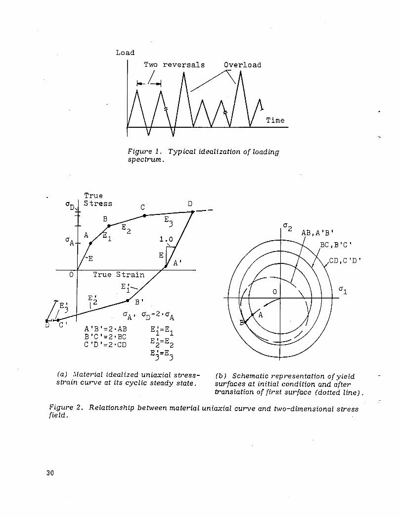
Load
True O'D, Stress
o
A'B'=2'AB B'C'=2'BC C'D'=2'CD
Two reversals Overload
~~ / Time
Figure 1. Typical idealization of loading spectrum.
D C_----y---
Ei=El E '=E 2 2 E'=E
3 3
AB,A'B'
(a) Material idealized uniaxial stressstrain curve at its cyclic steady state.
(b) Schematic representation of yield surfaces at initial condition and after translation of first surface (dotted line) .
Figure 2. Relationship between material uniaxial curve and two-dimensional stress field.
30
60/2
Yield Surface Center at 01
-, ~rxprager-~~~~----~--~~~ B
/ Bounding Surface Center at 02
alA II 02B
Figure 3. Incremental translations, da, representing three hardening rules. a 1 and a 2 represent total
translational components of surfaces; a 1 and a 2
represent stress components.
, \
1.0
log-log 6EP/2 1.0
log-log 2N
(a) AJaterial uniaxial relationship between stress amplitude and plastic strain amplitude
(b) Coffin-Manson low-cycle fatigue data of material uniaxial unnotched specimen.
at cyclic steady state.
Figure 4. Required input data for present approach.
31
32
Finite element integration points
Crack tip~ (!~ \ 1jPrinCiPal ~r-==::::::~===:~~l-~~/--\~~~~r---- tensile ..... ( ) Cra~k ~ stress Cyclic ~ ../ path plasticity zone
Figure 5. Location of discrete points in front of cr'ack tip for calculation of crack growth rate.
Max. Stress
L
IViax. Strain
Figure 6. Pair of reversals count.
t
---------I2a I- 2a/W=O.4
~v
Thickness, t=O.l inch (2.54 mm)
Crack length, 2a=1.0 inch ( 25 . '", :nm) I-a
P/2
+ + +
- --:. 4
tAr ~
(a) Geometry of panel. (b) Finite element model for onequarter of panel.
Figure 7. Example of a cracked panel under uniaxial loads.
kg
/ mm-
28.1
True Stress
ksi
76. /
r-:;:=.~--I\ . El. 0 '\ 067 E • .L i
Masing curve
E=10300. ksi 2 (7241. kg/mm )
True Strain, %
Figure 8. Idealized material curve in uniaxial cyclic steady state for cracked panel.
33
34
r:1m per cycle
- '~ 10 ~
40-4
d(2a)
dN inch per. cycle
" 10 -. .)
10
p
Small Plasticity + Ref. 6~ 1
20
50 100
/~
~ Gross Cyclic Plasticity Present Approach
100 200
I I 600 300
(a) Fully cyclic loading.
1
ksi(inf2
J 12 kg( mm) - "
Figure 9. Crack growth rate results for cracked panel and comparisons with small plasticity cases.
..
mm per cycle
d(2a) dN
inch per cycle
1O-2~
10-3 Time Small t Plast~city
lO_:ef. o~ _ -+#.1-VI
Gross Cyclic Plasticity
10-5 Present Approach
6K
"1
20 200 ksi (inf2"
50 100 200 300 600 kg(mm)-3/2
(b) Tensile cyclic loading.
Figure 9. Concluded.
35
36
2.
1 •
1.0
2.0
50.0
~~~ I- I ---i Time
2N=1000
d(2a)/dN
5·0 8.0 (in/cycle)xl05
100.0 200.0 (mm/cycle)xl05
Figure 10. Numerical results for cracked panel of effect of tensile overloads on crack growth rate.
..
3. mm 30. mm1f~ .- A U - 1. t Local 1 ~O • 4 mI? --I reinforcc-ment (j.9 In) area
(a) Typical section.
I~I--l ----.--'7~'5fEr'l ___ ~1 / L ~O 5/ K.. Local
I;. te€ral stiffener
~) v reinforcement area
(b) View A.
+
+ C--lS& .1..
(c) View B.
Figure 11. Details of an aircraft integral stiffened skin.
37
38
Thickness Change
(a) Finite element model.
Nominal Stress
21.7 kg/mm2 ~
(30.9ksi)
Time
(b) Applied compressive loading.
kg!mm2(ksi) 58.3 (82.9) 55.4 (78.8) 53.4 (76.0)
E=7240 2 kg/mm
(10300ksi)
Uniaxial Stress
Uniaxial
.004E I
Masing curve
(c) Material uniaxial curve.
Figure 12. Idealization of stiffened skin example.
(2N) Reversals·l0-J
~----~~--------~ Case 1 ___ 2_ Skin A 1.2 11. -------B 4.4 JO. E
C 20.0 100. J 60.0 500. E 10.0 1000.
(a) Equal damage curves indicating number of reversals to crack initiation.
Skin
-57. ~56. ~55.
54.
2 kg/mm ( 81.1 (79. 7 (78.2 (76.8
ksi) ) ) )
(b) Maximum von Mises stress distributions.
Figure 13. Results for uncracked stiffened skin.
39
40
Skin
--.---~-L
J.O mm (.012 in)
(a) Modified finite element models due to crack growth.
Case 1 Case 2
Skin Skin
2N=1000,6JoO,80000 2N=J4oo,27000
Case 1
Case 2
(b) Distributions of equal damage curves.
AB BC CD
AB BC'
Skin
'::2.,"d (2N) average
mm inch per two reversals
9.4 '10=~ 2.0'10_7 < 10
1.0'10=g J. J 010
(c) Crack growth rate and orientation.
Figure 14. Results for cracked stiffened skin.
t
1. Report No. 2. Government Accession No. 3. Recipient's Catalog No.
NASA CR-163101 4. Title and Subtitle 5. Report Date
A COMPUTER PROGRAlVl FOR CYCLIC PLASTICITY November 1980 AND STRUCTURAL FATIGUE ANALYSIS 6. Performing Organization Code
7. Author(sl 8. Performing Organization Report No.
I. Kalev ~-1139
10. Work Unit No.
9. Performing Organization Name and Address 506-53-64 NASA Dryden Flight Research Center P.O. Box 273 11. Contract or Grant No.
Edwards. California 93523
13. Type of Report and Period Covered
12. Sponsoring Agency Name and Address Contractor Report-Topical
National Research Council 14. Sponsoring Agency Code 2101 Constitution Avenue
Washington. D. C. 20418
15. Supplementary Notes
This work was performed by the author during his residence at the NASA Dryden Flight Research Center as a National Research Council Associate. Technical Monitor: Jerald M. Jenkins Program Coordinator: Dr. Eldon E. Kordes
16. Abstract
A computerized tool for the analysis of time-independent cyclic plasticity structural response, life to crack initiation prediction. and crack growth rate prediction for metallic materials is described. Three analytical items are combined: the finite element method with its associated numerical techniques for idealization of the structural component. cyclic plasticity models for idealization of the material behavior. and damage accumulation criteria for the fatigue failure.
17. Key Words (Suggested by Author(sll 18. Distribution Statement
Computer programs Finite element method Unclassified-Unlimited Crack initiation ;Vletal fatigue Crack propagation Plastic properties Cyclic loads Plasticity Elastoplasticity Structural analysis
Distribution category: 05 Fatigue life 19. Security Classi!. (of this report! 20. Security Classif. (of this page)
121
. No. of Pages 1 22. Price·
Unclassified Unclassified 42 A-02
*For sale by the National Technical Information Service, Springfield, Virginia 22161

End of Document
- I' .•.••
Related Documents