© Valeport Limited 2013
MIDAS Surveyor Operating Manual Page 1 0420805g - Midas Surveyor User Manual
VALEPORT LIMITED
MIDAS Surveyor
Operation Manual
Document Ref: 0420805 Date: October 2013 This confidential document was prepared by the staff of Valeport Limited, the Company, and is the property of the Company, which also owns the copyright therein. All rights conferred by the law of the copyright and by virtue of international copyright conventions are reserved to the Company. This document must not be copied, reprinted or reproduced in any material form, either wholly or in part, and the contents of this document, and any method or technique available therefrom, must not be disclosed to any other person whatsoever without the prior written consent of the Company. Valeport Limited, Tel: +44 (0)1803 869292 St. Peter’s Quay, Fax: +44 (0)1803 869293 Totnes, e-mail: [email protected] Devon, TQ9 5EW, Web: www.valeport.co.uk UK As part of our policy of continuous development, we reserve the right to alter, without prior notice, all specifications, designs, prices and conditions of supply for all our equipment.
Copyright 2013
© Valeport Limited 2013
MIDAS Surveyor Operating Manual Page 2 0420805g - Midas Surveyor User Manual
CHAPTER DESCRIPTION PAGE
1 INTRODUCTION .............................................................................................................................................................................. 4
2 SPECIFICATION .............................................................................................................................................................................. 5 2.1 MIDAS Surveyor ................................................................................................................................................... 5 2.2 Transducers .......................................................................................................................................................... 5
2.2.1 High frequency ................................................................................................................................................................. 5 2.2.2 Low frequency .................................................................................................................................................................. 5
2.3 GPS ...................................................................................................................................................................... 5 2.3.1 12 Channel GPS ............................................................................................................................................................... 5
2.4 Connectors ........................................................................................................................................................... 6
3 SYSTEM INSTALLATION ................................................................................................................................................................ 7 3.1 Transducers .......................................................................................................................................................... 7 3.2 Antennae .............................................................................................................................................................. 8 3.3 Batteries ................................................................................................................................................................ 8 3.4 Memory ................................................................................................................................................................. 9 3.5 Other inputs .......................................................................................................................................................... 9
3.5.1 Remote Event Marker ....................................................................................................................................................... 9 3.5.2 Differential GPS Correction ............................................................................................................................................... 9 3.5.3 Tidal Correction ................................................................................................................................................................ 9 3.5.4 Heave Correction .............................................................................................................................................................. 9 3.5.5 Sound Velocity ................................................................................................................................................................ 10 3.5.6 Gyrocompass / Auxiliary ................................................................................................................................................. 10 3.5.7 Data Output .................................................................................................................................................................... 10
4 OPERATION .................................................................................................................................................................................. 11 4.1 Run mode ........................................................................................................................................................... 12 4.2 System Setup...................................................................................................................................................... 13
4.2.1 Help ................................................................................................................................................................................ 13 4.2.2 Navigation ...................................................................................................................................................................... 13 4.2.3 Logging Setup ................................................................................................................................................................ 14
4.2.3.1 Log On/Off .............................................................................................................................................................. 14 4.2.3.2 Log Pause .............................................................................................................................................................. 14 4.2.3.3 Set Ident No. ........................................................................................................................................................... 15 4.2.3.4 Log Parameters ...................................................................................................................................................... 15 4.2.3.5 Sound Velocity Interval ........................................................................................................................................... 15 4.2.3.6 Tide Interval ............................................................................................................................................................ 16 4.2.3.7 Auxiliary Interval ..................................................................................................................................................... 16
4.2.4 RS232 Com Ports ........................................................................................................................................................... 16 4.2.5 Output Setup .................................................................................................................................................................. 17 4.2.6 Display setup .................................................................................................................................................................. 19
4.2.6.1 LCD delay ............................................................................................................................................................... 19 4.2.6.2 Grid Lat/Long .......................................................................................................................................................... 19 4.2.6.3 Display Input Number ............................................................................................................................................. 19 4.2.6.4 Contrast .................................................................................................................................................................. 19 4.2.6.5 Back Light ............................................................................................................................................................... 19
4.2.7 Geodetic Setup ............................................................................................................................................................... 20 4.2.7.1 Defaults .................................................................................................................................................................. 21 4.2.7.2 Changing Grid and Spheroid Parameters................................................................................................................ 21
4.2.8 Echosounder Setup ........................................................................................................................................................ 21 4.2.8.1 Internal/External Echosounder ................................................................................................................................ 21 4.2.8.2 E/S Velocity ............................................................................................................................................................ 22 4.2.8.3 Draft........................................................................................................................................................................ 22 4.2.8.4 Metres/Feet ............................................................................................................................................................ 22 4.2.8.5 Gating ..................................................................................................................................................................... 22 4.2.8.6 Single/Dual Frequency ............................................................................................................................................ 22 4.2.8.7 Vertical Scale .......................................................................................................................................................... 23 4.2.8.8 Horizontal Scale ...................................................................................................................................................... 23 4.2.8.9 Raw & Corrected .................................................................................................................................................... 23
4.2.9 GPS Setup ..................................................................................................................................................................... 23 4.2.9.1 GPS Type ............................................................................................................................................................... 23 4.2.9.2 GPS Reset .............................................................................................................................................................. 23 4.2.9.3 GPS RTCM baud .................................................................................................................................................... 23 4.2.9.4 Antenna Offset ........................................................................................................................................................ 24 4.2.9.5 Heading Source ...................................................................................................................................................... 24
4.2.10 Sensor Setup .................................................................................................................................................................. 24 4.2.10.1 Velocity Sensor ....................................................................................................................................................... 24 4.2.10.2 Tide Height Setup ................................................................................................................................................... 24 4.2.10.3 Heave Sensor ......................................................................................................................................................... 25 4.2.10.4 Gyro/Aux Setup ...................................................................................................................................................... 25 4.2.10.5 Set PIC Op Modes .................................................................................................................................................. 25
4.2.11 Time Setup ..................................................................................................................................................................... 26 4.2.11.1 1/2 Hour Time Zones .............................................................................................................................................. 26 4.2.11.2 Set Time ................................................................................................................................................................. 26
4.2.12 Beep, Relay, etc. ............................................................................................................................................................ 27 4.2.12.1 Beep ....................................................................................................................................................................... 27
© Valeport Limited 2013
MIDAS Surveyor Operating Manual Page 3 0420805g - Midas Surveyor User Manual
4.2.12.2 Relay ...................................................................................................................................................................... 27 4.2.12.3 External Power ....................................................................................................................................................... 27
4.2.13 Utilities ............................................................................................................................................................................ 28 4.2.13.1 Simulate Mode ........................................................................................................................................................ 28 4.2.13.2 Set All Default ......................................................................................................................................................... 28 4.2.13.3 Emulate PC Keyboard ............................................................................................................................................ 28 4.2.13.4 Echo External RTCM .............................................................................................................................................. 29
4.2.14 Command Mode ............................................................................................................................................................. 29 4.2.15 Power Off ....................................................................................................................................................................... 29
5 SURVEYLOG SOFTWARE ............................................................................................................................................................ 30 5.1 Introduction ......................................................................................................................................................... 30 5.2 Installation ........................................................................................................................................................... 30 5.3 Establishing Communications ............................................................................................................................. 31 5.4 File Management & Data Upload ........................................................................................................................ 32 5.5 Translating Data .................................................................................................................................................. 33 5.6 Viewing Data Files .............................................................................................................................................. 34
5.6.1 ASCII Data Files ............................................................................................................................................................. 34 5.6.1.1 ASCII File Data Format ........................................................................................................................................... 35
5.6.2 Discarding Erroneous Depth Data................................................................................................................................... 36 5.6.3 Valeport Format Files ..................................................................................................................................................... 36 5.6.4 XYZ Format Files ............................................................................................................................................................ 38
5.7 About .................................................................................................................................................................. 39
6 WIRING SCHEDULES ................................................................................................................................................................... 40
© Valeport Limited 2013
MIDAS Surveyor Operating Manual Page 4 0420805g - Midas Surveyor User Manual
1 INTRODUCTION
This manual describes the operation of the Valeport MIDAS Surveyor GPS Echosounder, and its associated PC software
SurveyLog.
The MIDAS Surveyor is a hydrographic survey system, logging a time series of position and depth data. Real time data
is displayed on the integral graphics LCD screen and output in a variety of industry standard formats, and all logged data
may subsequently be uploaded to PC. More advanced features of the MIDAS Surveyor include the ability to take
corrective data from external instruments, including Valeport tide gauges & sound velocity sensors, together with heave
sensors and gyrocompasses. Additionally, a second echosounder transducer may also be used.
The system logs data asynchronously. That is to say, it will log all incoming data regardless of the update rate or exact
timing of each data channel, and will log each data input in sequence. The onboard microprocessor applies an accurate
time stamp to each data point, ensuring that a complete time series record of each data input can be generated, together
with interpolated position and depth information. Any corrective data received from a heave sensor or tide gauge can be
applied in real time to the depth data, and the user may choose whether to log or output either the corrected or
uncorrected data.
The instrument may be supplied with or without an integral GPS receiver. Valeport offer the Hemisphere Crescent SX2
GPS board. The 12-channel, L1 DGPS board features SBAS support, along with Hemisphere GPS’ exclusive
COAST™and e-Dif® technologies, making it easy to get an accurate signal, anytime, anywhere. Accuracy and stability
are excellent due to Crescent Receiver Technology’s more accurate code phase measurements, multipath mitigation
improvements, and fewer discrete receiver components.
The scope of this manual does not include a detailed discussion of the SBAS (Satellite Based Augmentation System)
systems, but they can be simply described as a free differential GPS correction, transmitted from geostationary satellites.
There are currently three SBAS systems active in different geographical areas: WAAS in North America, EGNOS in
Europe and the Middle East, and MSAS in the Far East. The accuracy of the differential corrections obtained from the
SBAS systems varies depending on the receiver’s position within the footprint, but can typically be relied upon to give
overall accuracy levels in the region of 1 – 5m, depending on receiver type.
Valeport has developed its own single beam echosounder system, which utilises advanced Digital Signal Processing
techniques to give high levels of accuracy and consistent performance. The system is integral to the MIDAS Surveyor,
which thus requires only a standard analogue transducer to be connected. The system has two channels as standard,
optimised for 210kHz and 33kHz transducers respectively. The user may choose to use either or both of these channels,
using Valeport’s standard supply transducers or their own choice. Alternatively, the MIDAS Surveyor can accept digital
transducer inputs, or single / dual channel data from any standard third party echosounder system.
© Valeport Limited 2013
MIDAS Surveyor Operating Manual Page 5 0420805g - Midas Surveyor User Manual
2 SPECIFICATION
2.1 MIDAS SURVEYOR
Materials Injection moulded ABS case, sealed to IP67, with automatic pressure balancing valve.
Dimensions 50 x 40 x 20cm
Weight 15kg
Display 240 x 128 pixel graphics LCD screen.
Power Accepts 12 – 24vDC external input for running or charging. Draws approximately 200mA at 12v.
Batteries Internal 8.4Ah sealed lead acid batteries, charging automatically when external power is applied.
Memory 16Mbyte FLASH memory (holds approximately 30 hours’ data). Optional 32Mbyte FLASH memory.
2.2 TRANSDUCERS
2.2.1 HIGH FREQUENCY
Frequency 210kHz (200kHz option)
Accuracy greater of ±0.01m or ±0.02% reading.
Resolution 0.01m
Range 0.3 to 100m
Beam Width 7.5°
Sample Rate 6Hz
Dimensions 12cmØ
Cable Length 10m
2.2.2 LOW FREQUENCY
Frequency 33kHz (30kHz option)
Accuracy greater of ±0.01m or ±0.02% reading.
Resolution 0.01m
Range 0.3 to 100m
Beam Width 16.5°
Sample Rate 6Hz
Dimensions 25cmØ
Cable Length 10m
2.3 GPS
2.3.1 12 CHANNEL GPS
Type Hemisphere Crescent SX2 DGPS receiver module.
Differential Onboard SBAS Correction
Accuracy Horizontal Accuracy: <2.5 m 95% confidence (autonomous, no SA)
Update Rate 1Hz
Antenna Combined GPS / SBAS plane antenna (IP67), 5m cable
© Valeport Limited 2013
MIDAS Surveyor Operating Manual Page 6 0420805g - Midas Surveyor User Manual
}
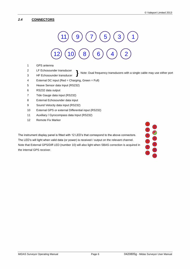
2.4 CONNECTORS
11 9 7 5 3 1
24681012
1 GPS antenna
2 LF Echosounder transducer
3 HF Echosounder transducer
4 External DC input (Red = Charging, Green = Full)
5 Heave Sensor data Input (RS232)
6 RS232 data output
7 Tide Gauge data input (RS232)
8 External Echosounder data input
9 Sound Velocity data input (RS232)
10 External GPS or external Differential input (RS232)
11 Auxiliary / Gyrocompass data Input (RS232)
12 Remote Fix Marker
The instrument display panel is fitted with 12 LED’s that correspond to the above connectors.
The LED’s will light when valid data (or power) is received / output on the relevant channel.
Note that External GPS/Diff LED (number 10) will also light when SBAS correction is acquired in
the internal GPS receiver.
Note: Dual frequency transducers with a single cable may use either port
11
9
7
5
3
12
4
6
8
10
12
© Valeport Limited 2013
MIDAS Surveyor Operating Manual Page 7 0420805g - Midas Surveyor User Manual
3 SYSTEM INSTALLATION
3.1 TRANSDUCERS
Valeport standard transducers are supplied with a mounting bracket and clamps to allow easy attachment to the
operator’s vessel. The system is designed to be used in an “over the side” configuration, and the transducer may be
fitted to either the front or side of the vessel, away from sources of disturbance such as propellers.
210kHz Transducer:
Feed the signal cable through the bracket, so that the transducer fits inside the cone.
Fix the transducer to the bracket using the 6 x M6 screws provided.
33kHz Transducer
Feed the signal cable through the bracket, and align the plate to the top of the transducer.
Fix the transducer to the bracket using the 3 x M8 screws and nuts provided.
Combined Transducer
Feed the signal cable through the bracket, and align the plate to the top of the transducer.
Fix the transducer to the bracket using the 4 x M8 screws and nuts provided.
All Transducers
Loosen the fixing clamp sufficiently to allow the loop end to be placed over the bracket. Tighten the nuts with a
13mm spanner until the bracket is securely held.
The transducer may now be fitted to a suitable vertical pole on the vessel. The fixing clamp will accept a pole up to
50mm diameter.
Loosen or remove the final four M6 nuts and the clamp plate, and place the clamp around the pole.
Refit the clamp plate and tighten the nuts to hold the transducer securely in place. Ensure that the transducer is
completely submerged, and is pointing as near as possible vertically downwards. If anything, the transducer should
point a degree or two forward of vertical, to help eliminate any cavitation effects at higher speed. The combined
transducer should be fitted with the sloped edge facing forwards.
The distance of the transducer face below the water surface should be measured; this is applied to the echosounder
data to give a true depth reading, rather than just the distance below the transducer (see Section 4.2.9.3).
The signal cable from the transducer should be terminated in the connection box provided, according to the wiring
information given in Section 6. The system is supplied in this manner to allow the cable to be easily routed around
the boat, or to allow the user to operate the instrument with alternative, possibly permanently installed transducers.
The transducer fixing pole may be stabilised with wires running fore and aft.
Finally, connect the transducer cable to the main MIDAS Surveyor unit. There are two connectors for echosounder
transducers – one for the high frequency (210kHz) transducer, and one for the low frequency (33kHz) transducer,
but either port can be used. Note that the pins are connected in parallel within the unit, so that a dual frequency
transducer with a single cable (if correctly wired as per Section 6) can be fitted to either connector.
Note that the instrument is initially nominally set up for a sound velocity of 1500m/s. The user may wish to alter this
according to measured sound velocity data, or by using a bar check method. The Valeport SoundBar 2 Digital Bar
Checker may be used to provide appropriate sound velocity and draft settings, or a more traditional bar check procedure
may be carried out. Please refer to Sections 4.2.9.2 and 4.2.9.3 for details of how to alter these instrument settings.
© Valeport Limited 2013
MIDAS Surveyor Operating Manual Page 8 0420805g - Midas Surveyor User Manual
3.2 ANTENNAE
The GPS antenna is supplied with a mounting spar.
Pass the antenna cable through the spar, and screw the spar into the base of the antenna.
Loosen the fixing clamp sufficiently to allow the loop end to be placed over the spar. Tighten the nuts with a 13mm
spanner until the bracket is securely held.
The antenna may now be fitted to a suitable vertical pole on the vessel. The fixing clamp will accept a pole up to
50mm diameter. This should be fitted vertically above the transducer, in an open area with as clear a view of the
sky as possible.
Connect the antenna cable to the GPS Antenna connector on the main MIDAS Surveyor unit.
A similar spar and clamping method will be used as for the main GPS Antenna. Connect this cable to the External
GPS / Differential input connector on the main MIDAS Surveyor unit.
3.3 BATTERIES
The system is fitted with 4 x 2.1Ah sealed lead acid batteries. These are shipped from Valeport fully charged, but the
user would be wise to recharge them before relying on them in a field deployment.
The system is designed so that it will always draw its operating power from these internal batteries. The system is
supplied with an external DC input lead, which should be used to charge the batteries. A DC input of 12 – 24vDC is
acceptable. The batteries will be trickle charged whether the unit is turned on or off; when off, the batteries should fully
recharge in approximately 8 hours.
If the system is not used for long period of time the batteries may be discharged to a point the internal charging circuit will
not be able to recharge the batteries and the instrument will need to be returned to Valeport. It is recommended that if
the system is left on trickle charge when not used, or a top up charge applied once a month.
Power consumption of the unit will depend on exact configuration, including the number of transducers used, and
whether the LCD backlight is used. At worst, a fully charged set of batteries should last in excess of 24 hours without
recharging.
Typical Power consumption is:
Main system, including GPS (12 channel) and LCD screen 90mA @ 12v
Single transducer 45mA @ 12v
Second transducer 15mA @ 12v
Backlight (user variable, but typically) 50mA @ 12v
Total 200mA @ 12v
8.4Ah / 0.2A continuous drain = 42 hours.
Assume 75% efficiency (worst case) = 25½ hours.
Note that certain system features such as the internal clock and data logging parameters depend on the batteries being
connected. The instrument will automatically shut down with warning if the power drains too low, preserving enough life
to maintain these functions. However, if the batteries are disconnected, or the instrument is left unused and discharged
for a long time, the user may need to re-enter such setup functions before next use. Refer to the appropriate sections of the
manual.
© Valeport Limited 2013
MIDAS Surveyor Operating Manual Page 9 0420805g - Midas Surveyor User Manual
3.4 MEMORY
The unit is fitted with 16Mbyte FLASH memory (32Mbyte optional). The instrument will log data at up to 0.5Mbyte per
hour, so the memory will last for a nominal 32 hours (or 64 hours). The FLASH memory is non-volatile, so no data will be
lost even if the instrument batteries are completely run down.
3.5 OTHER INPUTS
3.5.1 REMOTE EVENT MARKER
The MIDAS Surveyor is fitted with a Marker button to allow the user to mark specific points during the survey. This cable
should be fitted to the appropriate connector. The mark may be made either by pressing the button on the remote
marker cable during operation, or by pressing the F3 key on the instrument panel. Note that the addition of a mark to the
record is indicated by a beep from the instrument, and by the display of a vertical line on the graphical trace. Marking will
only occur while the instrument logging function is turned ON.
3.5.2 DIFFERENTIAL GPS CORRECTION
The instrument is supplied with a 12 DGPS receiver. If the user has an alternative GPS or Differential receiver, it should
be connected to the appropriate connector on the MIDAS Surveyor (wired as per Section 6). If an external differential
source is used, the unit will automatically assume that it is better than the standard SBAS correction, and will use it
instead. If a full external GPS input is used, the internal GPS receiver should be disabled, as described in Section
4.2.10.1.
3.5.3 TIDAL CORRECTION
The depth of water under the boat will naturally vary with the tide cycle. The MIDAS Surveyor has been designed to take
in data from an external source, typically a Valeport Model 740 tide gauge radio receiver. This data is logged within the
unit as it is received (typically at 1 or 5 minute intervals), and may be used to provide a real time correction of the water
depth as measured by the echosounder.
The tide gauge receiver unit should be connected to the Surveyor using the standard RS232 input lead (wired as
described in Section 6). The tidal data correction function should be enabled / disabled in the MIDAS Surveyor, as
described in Section 4.2.11.2.
3.5.4 HEAVE CORRECTION
Wave activity and boat motion may cause the depth of water below the echosounder transducer to change rapidly. This
effect may be eliminated by using a Heave sensor to measure the rapid changes in vertical position of the transducer. If
the vessel is fitted with such a sensor, its output may be logged by the MIDAS Surveyor and used to correct the depth
readings in real time.
The Heave Sensor should be connected to the Surveyor using the standard RS232 input lead (wired as described in
Section 6). The heave correction function should be enabled / disabled in the MIDAS Surveyor, as described in Section
4.2.10.3.
© Valeport Limited 2013
MIDAS Surveyor Operating Manual Page 10 0420805g - Midas Surveyor User Manual
3.5.5 SOUND VELOCITY
Variation of sound velocity is one of the most critical sources of error in the use of echosounders. The sound velocity
may change significantly in both vertical and horizontal aspects of the survey area, and it is important that consideration
is paid to this to give the best results possible.
The system is supplied setup to use a nominal sound velocity of 1500m/s. It is not possible to change this value whilst
the system is running, but it may be changed when the unit is in standby mode. Details of how to do this are given in
Section 4.2.9.3. It is possible however for the MIDAS Surveyor to log sound velocity data whilst a survey is in progress,
and this may be used to provide data correction during post processing (the SurveyLog software makes no provision for
this). The instrument will accept two types of Valeport sound velocity input – either a continuous input from a fixed
miniSVS sensor that will measure sound velocity variations in a horizontal plane, or irregular input strings from a
SoundBar digital bar checker that will give a summary of the mean sound velocity over a profile, performed at the user’s
discretion.
3.5.6 GYROCOMPASS / AUXILIARY
The MIDAS Surveyor does not currently feature a navigation, or tracking system. However, it is able to compensate for
the GPS antenna being sited at a different location to the echosounder transducer. The user is invited to enter this offset
value during the system setup (see Section 4.2.10.4), but this offset is naturally subject to variations in vessel heading.
Whilst a heading value is generated by the GPS receiver system, this may be inaccurate at slow speeds, resulting in
errors in the position / depth data. The user may decide that to minimise such errors, an independent vessel heading
input is necessary; this would typically be supplied by a gyrocompass.
The Gyrocompass should be connected to the Surveyor using the standard RS232 input lead (wired as described in
Section 6). The heading correction function should be enabled / disabled in the MIDAS Surveyor, as described in
Section 4.2.11.4.
Alternatively, the gyro input port may be used to accept any unspecified auxiliary RS232 input that the user may wish to
additionally record. Any such sensor should be connected to the Surveyor using the standard RS232 input lead (wired
as described in Section 6). The data string will automatically be recorded as it comes into the unit.
3.5.7 DATA OUTPUT
The MIDAS Surveyor can output RS232 data from all input channels in real time in a variety of industry standard formats:
POSITION DEPTH OTHER CHANNELS
ANY, ALL or NONE OF: OFF OFF
GGA ODOM ET ECHO INPUT
VTG ATLAS 25
POS DBS
SAT DBT
Full details of how to select the appropriate data output string and their formats are given in Section 4.2.6.
The RS232 output lead should be used. It is wired as described in Section 6.
© Valeport Limited 2013
MIDAS Surveyor Operating Manual Page 11 0420805g - Midas Surveyor User Manual
4 OPERATION
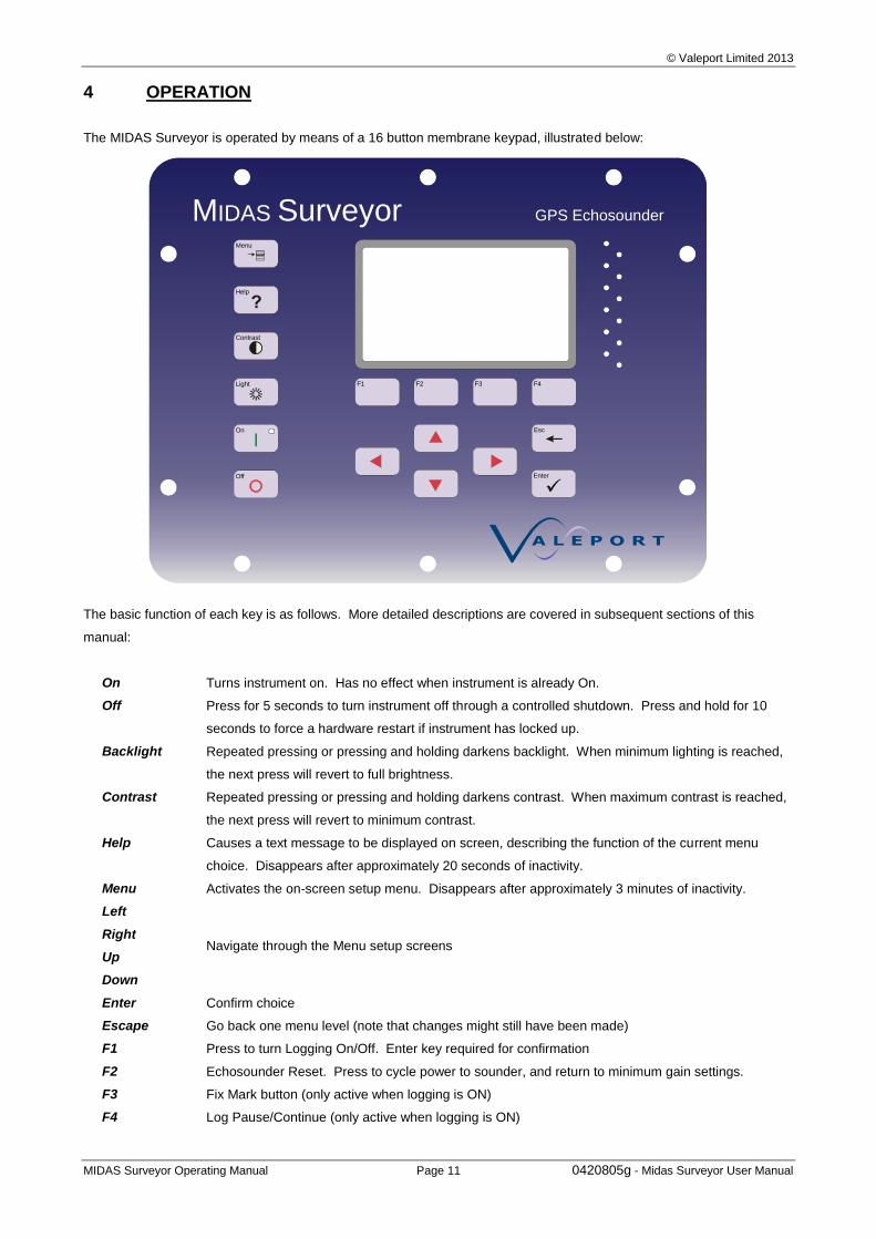
The MIDAS Surveyor is operated by means of a 16 button membrane keypad, illustrated below:
The basic function of each key is as follows. More detailed descriptions are covered in subsequent sections of this
manual:
On Turns instrument on. Has no effect when instrument is already On.
Off Press for 5 seconds to turn instrument off through a controlled shutdown. Press and hold for 10
seconds to force a hardware restart if instrument has locked up.
Backlight Repeated pressing or pressing and holding darkens backlight. When minimum lighting is reached,
the next press will revert to full brightness.
Contrast Repeated pressing or pressing and holding darkens contrast. When maximum contrast is reached,
the next press will revert to minimum contrast.
Help Causes a text message to be displayed on screen, describing the function of the current menu
choice. Disappears after approximately 20 seconds of inactivity.
Menu Activates the on-screen setup menu. Disappears after approximately 3 minutes of inactivity.
Left
Navigate through the Menu setup screens Right
Up
Down
Enter Confirm choice
Escape Go back one menu level (note that changes might still have been made)
F1 Press to turn Logging On/Off. Enter key required for confirmation
F2 Echosounder Reset. Press to cycle power to sounder, and return to minimum gain settings.
F3 Fix Mark button (only active when logging is ON)
F4 Log Pause/Continue (only active when logging is ON)
Off
Help
On
Contrast
Light
M SurveyorIDAS GPS Echosounder
Enter
F1 F2 F3 F4
Esc
Menu
© Valeport Limited 2013
MIDAS Surveyor Operating Manual Page 12 0420805g - Midas Surveyor User Manual
Once the system components have been connected together, the MIDAS Surveyor should be turned on by pressing the
“On” button on the display panel. “On” status will be indicated by a blue LED behind the On button. The display will
show an introduction screen giving the instrument serial number and version for about 10 seconds. The screen will then
immediately show Run mode (illustrated below).
Note that incoming data will be displayed at all times – there is no stop/go function, simply a logging on/off function.
The operating status of the instrument at switch on will depend on how it was previously turned off:
If a normal, controlled shutdown has been performed (by pressing the Off key), the MIDAS Surveyor will show data
on screen, but it will not be immediately recorded until the user instructs the instrument to do so.
If the instrument has had an uncontrolled shutdown (power failure, software or hardware reset), the instrument will
automatically revert to the status it was in before the shutdown. That is to say, if the instrument was not logging
data, then it will continue to not log the data. If the instrument was logging data, then it will continue to do so,
although it will begin a new data file.
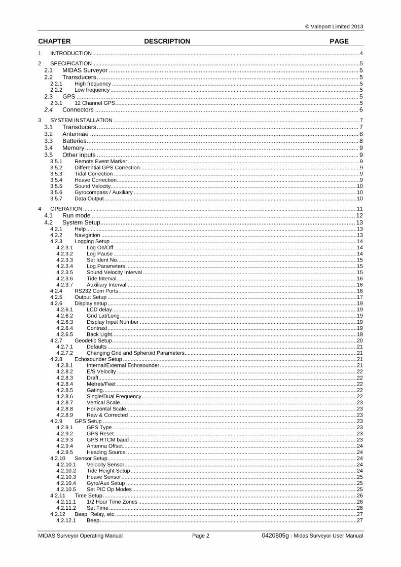
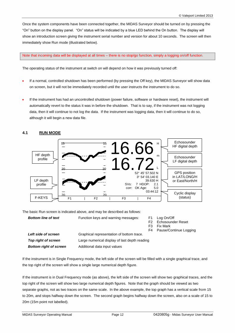
4.1 RUN MODE
The basic Run screen is indicated above, and may be described as follows:
Bottom line of text Function keys and warning messages: F1 Log On/Off F2 Echosounder Reset F3 Fix Mark F4 Pause/Continue Logging
Left side of screen Graphical representation of bottom trace.
Top right of screen Large numerical display of last depth reading
Bottom right of screen Additional data input values
If the instrument is in Single Frequency mode, the left side of the screen will be filled with a single graphical trace, and
the top right of the screen will show a single large numerical depth figure.
If the instrument is in Dual Frequency mode (as above), the left side of the screen will show two graphical traces, and the
top right of the screen will show two large numerical depth figures. Note that the graph should be viewed as two
separate graphs, not as two traces on the same scale. In the above example, the top graph has a vertical scale from 15
to 20m, and stops halfway down the screen. The second graph begins halfway down the screen, also on a scale of 15 to
20m (15m point not labelled).
15 15
20 20
20 20
16.66 16.72
H
L
m
52 45' 57.502 N
3 54' 03.140 E 39.630 H
SVs: 7 HDOP: 2.1 corr: OK Age: 5.0
03:44:12
F1 | F2 | F3 | F4
Echosounder HF digital depth
Echosounder LF digital depth
GPS position in LAT/LONG/H or East/North/H
Cyclic display (status)
LF depth profile
HF depth profile
F-KEYS
© Valeport Limited 2013
MIDAS Surveyor Operating Manual Page 13 0420805g - Midas Surveyor User Manual
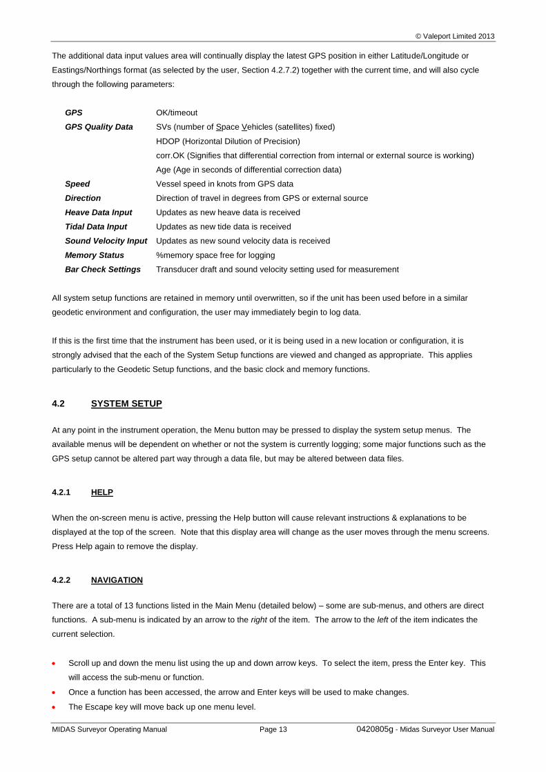
The additional data input values area will continually display the latest GPS position in either Latitude/Longitude or
Eastings/Northings format (as selected by the user, Section 4.2.7.2) together with the current time, and will also cycle
through the following parameters:
GPS OK/timeout
GPS Quality Data SVs (number of Space Vehicles (satellites) fixed)
HDOP (Horizontal Dilution of Precision)
corr.OK (Signifies that differential correction from internal or external source is working)
Age (Age in seconds of differential correction data)
Speed Vessel speed in knots from GPS data
Direction Direction of travel in degrees from GPS or external source
Heave Data Input Updates as new heave data is received
Tidal Data Input Updates as new tide data is received
Sound Velocity Input Updates as new sound velocity data is received
Memory Status %memory space free for logging
Bar Check Settings Transducer draft and sound velocity setting used for measurement
All system setup functions are retained in memory until overwritten, so if the unit has been used before in a similar
geodetic environment and configuration, the user may immediately begin to log data.
If this is the first time that the instrument has been used, or it is being used in a new location or configuration, it is
strongly advised that the each of the System Setup functions are viewed and changed as appropriate. This applies
particularly to the Geodetic Setup functions, and the basic clock and memory functions.
4.2 SYSTEM SETUP
At any point in the instrument operation, the Menu button may be pressed to display the system setup menus. The
available menus will be dependent on whether or not the system is currently logging; some major functions such as the
GPS setup cannot be altered part way through a data file, but may be altered between data files.
4.2.1 HELP
When the on-screen menu is active, pressing the Help button will cause relevant instructions & explanations to be
displayed at the top of the screen. Note that this display area will change as the user moves through the menu screens.
Press Help again to remove the display.
4.2.2 NAVIGATION
There are a total of 13 functions listed in the Main Menu (detailed below) – some are sub-menus, and others are direct
functions. A sub-menu is indicated by an arrow to the right of the item. The arrow to the left of the item indicates the
current selection.
Scroll up and down the menu list using the up and down arrow keys. To select the item, press the Enter key. This
will access the sub-menu or function.
Once a function has been accessed, the arrow and Enter keys will be used to make changes.
The Escape key will move back up one menu level.
© Valeport Limited 2013
MIDAS Surveyor Operating Manual Page 14 0420805g - Midas Surveyor User Manual
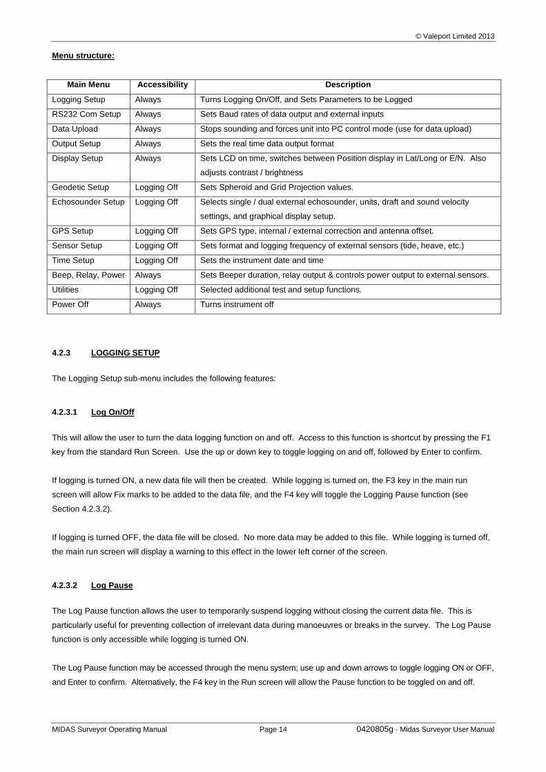
Menu structure:
Main Menu Accessibility Description
Logging Setup Always Turns Logging On/Off, and Sets Parameters to be Logged
RS232 Com Setup Always Sets Baud rates of data output and external inputs
Data Upload Always Stops sounding and forces unit into PC control mode (use for data upload)
Output Setup Always Sets the real time data output format
Display Setup Always Sets LCD on time, switches between Position display in Lat/Long or E/N. Also
adjusts contrast / brightness
Geodetic Setup Logging Off Sets Spheroid and Grid Projection values.
Echosounder Setup Logging Off Selects single / dual external echosounder, units, draft and sound velocity
settings, and graphical display setup.
GPS Setup Logging Off Sets GPS type, internal / external correction and antenna offset.
Sensor Setup Logging Off Sets format and logging frequency of external sensors (tide, heave, etc.)
Time Setup Logging Off Sets the instrument date and time
Beep, Relay, Power Always Sets Beeper duration, relay output & controls power output to external sensors.
Utilities Logging Off Selected additional test and setup functions.
Power Off Always Turns instrument off
4.2.3 LOGGING SETUP
The Logging Setup sub-menu includes the following features:
4.2.3.1 Log On/Off
This will allow the user to turn the data logging function on and off. Access to this function is shortcut by pressing the F1
key from the standard Run Screen. Use the up or down key to toggle logging on and off, followed by Enter to confirm.
If logging is turned ON, a new data file will then be created. While logging is turned on, the F3 key in the main run
screen will allow Fix marks to be added to the data file, and the F4 key will toggle the Logging Pause function (see
Section 4.2.3.2).
If logging is turned OFF, the data file will be closed. No more data may be added to this file. While logging is turned off,
the main run screen will display a warning to this effect in the lower left corner of the screen.
4.2.3.2 Log Pause
The Log Pause function allows the user to temporarily suspend logging without closing the current data file. This is
particularly useful for preventing collection of irrelevant data during manoeuvres or breaks in the survey. The Log Pause
function is only accessible while logging is turned ON.
The Log Pause function may be accessed through the menu system; use up and down arrows to toggle logging ON or OFF,
and Enter to confirm. Alternatively, the F4 key in the Run screen will allow the Pause function to be toggled on and off.
© Valeport Limited 2013
MIDAS Surveyor Operating Manual Page 15 0420805g - Midas Surveyor User Manual
4.2.3.3 Set Ident No.
Each data file may be assigned an Identification Number to aid data interpretation. Use the up and down keys to scroll
from 0 to 99, and Enter to confirm. The chosen Ident Number will be applied to all subsequent data files, until it is
changed again.
4.2.3.4 Log Parameters
As well as the basic parameters of depth and position, the MIDAS Surveyor will also accept data inputs from other
devices. In particular, Heave and Tide data inputs can be used to provide corrective information for the Depth data. The
MIDAS Surveyor is capable of performing these corrections in real time, so that only true depth values are displayed and
logged. This feature is actually turned on/off in the echosounder setup menu system (see Section 4.2.9.9). The Log
Parameters feature simply allows the user to determine which of the Depth / Heave / Tide data inputs are to be recorded;
for example, it may be decided that if corrected data is logged, there is no need to keep a record of what those corrective
Heave and Tide values were. The following combinations are possible:
If Real Time correction is ON
CORR.ONLY Corrected Depth value only
CORR+HEAVE Corrected Depth value and Heave input
COR+HVE+TID Corrected Depth value, together with Heave and Tide values.
CORR+TIDE Corrected Depth value and Tide input
If Real Time correction is OFF
RAW ONLY Uncorrected Depth value only
RAW+ HEAVE Uncorrected Depth value and Heave input
RAW+HVE+TID Uncorrected Depth value, together with Heave and Tide values.
RAW+ TIDE Uncorrected Depth value and Tide input
In all cases, use up and down to scroll through the available options, and Enter to confirm.
The Log Parameters function may only be altered if Logging is OFF.
4.2.3.5 Sound Velocity Interval
The MIDAS Surveyor will accept a real time input from a Valeport Sound Velocity sensor. Whilst this input is not used to
provide real time correction of the Depth data, it may be useful in post processing functions. Data from these sensors is
at variable rates, from 16Hz to 1Hz; the user may decide that logging of all these data points is unnecessary. The "SVEL
interval" function allows only selected data points from this sensor to be logged to memory.
Use up and down arrows to scroll through the logging interval in 1 second increments, from OFF through to 300 seconds
(5 minutes), and Enter to confirm. Note that the instrument will log the last measured data point at the set interval. The
display will continue to show data at the rate at which it is received.
© Valeport Limited 2013
MIDAS Surveyor Operating Manual Page 16 0420805g - Midas Surveyor User Manual
4.2.3.6 Tide Interval
The MIDAS Surveyor will accept a real time tidal input from a choice of sources. Data from such sources may be
available at variable rates from 1Hz downwards; the user may decide that logging of all these data points is unnecessary.
The "TIDE interval" function allows only selected data points from this input to be logged to memory.
Use up and down arrows to scroll through the logging interval in 1 second increments, from OFF through to 300 seconds
(5 minutes), and F3 to confirm. Note that the instrument will log the last measured data point at the set interval. The
display will continue to show data at the rate at which it is received.
4.2.3.7 Auxiliary Interval
The MIDAS Surveyor will accept a real time auxiliary input from any CRLF terminated RS232 ASCII text source (of less
than 256 characters) - typically this port may be used for Heading input from a Gyrocompass. Data from such sources
may be available at variable rates from 1Hz downwards; the user may decide that logging of all these data points is
unnecessary. The "AUX interval" function allows only selected data points from this input to be logged to memory.
Use up and down arrows to scroll through the logging interval in 1 second increments, from OFF through to 300 seconds
(5 minutes), and F3 to confirm. Note that the instrument will log the last measured data point at the set interval. The
display will continue to show data at the rate at which it is received.
4.2.4 RS232 COM PORTS
The MIDAS Surveyor is fitted with a total of 7 serial ports for data input / output. This sub-menu allows the baud rate of
each port to be configured to suit.
Data output is only available on the Main Port - this should also be used for all PC communications. The remaining ports
are numbered 1 to 6, and are configured for use with the following data input types. All ports are RS232 only, 8 data bits,
1 stop bit, No Parity.
Serial PC Com Data output and PC communications.
Serial 1 External GPS or Differential Input
Serial 2 External digital echosounder input
Serial 3 Sound Velocity Input
Serial 4 Tide Input
Serial 5 Heave Input
Serial 6 Auxiliary (or Gyrocompass) Input
To change the baud rate of each port, select it from the sub-menu. Use up and down arrows to scroll through the
available baud rates, and Enter to confirm:
2400 38400
4800 57600 (Main Port Only)
9600 76800 (Data Input Ports Only)
19200 115200
Note that for data upload to PC it is recommended that the highest possible baud rate is used.
© Valeport Limited 2013
MIDAS Surveyor Operating Manual Page 17 0420805g - Midas Surveyor User Manual
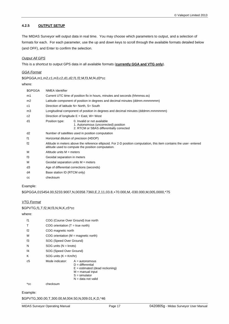
4.2.5 OUTPUT SETUP
The MIDAS Surveyor will output data in real time. You may choose which parameters to output, and a selection of
formats for each. For each parameter, use the up and down keys to scroll through the available formats detailed below
(and OFF), and Enter to confirm the selection.
Output All GPS
This is a shortcut to output GPS data in all available formats (currently GGA and VTG only).
GGA Format
$GPGGA,m1,m2,c1,m3,c2,d1,d2,f1,f2,M,f3,M,f4,d3*cc
where:
$GPGGA NMEA Identifier
m1 Current UTC time of position fix in hours, minutes and seconds (hhmmss.ss)
m2 Latitude component of position in degrees and decimal minutes (ddmm.mmmmmm)
c1 Direction of latitude N= North, S= South
m3 Longitudinal component of position in degrees and decimal minutes (dddmm.mmmmmm)
c2 Direction of longitude E = East, W= West
d1 Position type: 0. Invalid or not available 1. Autonomous (uncorrected) position 2. RTCM or SBAS differentially corrected
d2 Number of satellites used in position computation
f1 Horizontal dilution of precision (HDOP)
f2 Altitude in meters above the reference ellipsoid. For 2-D position computation, this item contains the user- entered altitude used to compute the position computation.
M Altitude units M = meters
f3 Geoidal separation in meters
M Geoidal separation units M = meters
d3 Age of differential corrections (seconds)
d4 Base station ID (RTCM only)
cc checksum
Example:
$GPGGA,015454.00,5233.9007,N,00358.7360,E,2,11,03.8,+70.000,M,-030.000,M,005,0000,*75
VTG Format
$GPVTG,f1,T,f2,M,f3,N,f4,K,c5*cc
where:
f1 COG (Course Over Ground) true north
T COG orientation (T = true north)
f2 COG magnetic north
M COG orientation (M = magnetic north)
f3 SOG (Speed Over Ground)
N SOG units (N = knots)
f4 SOG (Speed Over Ground)
K SOG units (K = Km/hr)
c5 Mode indicator: A = autonomous D = differential E = estimated (dead reckoning) M = manual input S = simulator N = data not valid
*cc checksum
Example:
$GPVTG,300.00,T,300.00,M,004.50,N,009.01,K,D,*46
© Valeport Limited 2013
MIDAS Surveyor Operating Manual Page 18 0420805g - Midas Surveyor User Manual
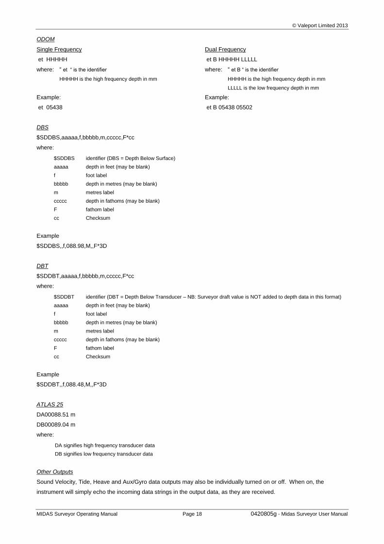
ODOM
Single Frequency Dual Frequency
et HHHHH et B HHHHH LLLLL
where: “ et “ is the identifier
HHHHH is the high frequency depth in mm
where: “ et B “ is the identifier
HHHHH is the high frequency depth in mm
LLLLL is the low frequency depth in mm
Example: Example:
et 05438 et B 05438 05502
DBS
$SDDBS,aaaaa,f,bbbbb,m,ccccc,F*cc
where:
$SDDBS identifier (DBS = Depth Below Surface)
aaaaa depth in feet (may be blank)
f foot label
bbbbb depth in metres (may be blank)
m metres label
ccccc depth in fathoms (may be blank)
F fathom label
cc Checksum
Example
$SDDBS,,f,088.98,M,,F*3D
DBT
$SDDBT,aaaaa,f,bbbbb,m,ccccc,F*cc
where:
$SDDBT identifier (DBT = Depth Below Transducer – NB: Surveyor draft value is NOT added to depth data in this format)
aaaaa depth in feet (may be blank)
f foot label
bbbbb depth in metres (may be blank)
m metres label
ccccc depth in fathoms (may be blank)
F fathom label
cc Checksum
Example
$SDDBT,,f,088.48,M,,F*3D
ATLAS 25
DA00088.51 m
DB00089.04 m
where:
DA signifies high frequency transducer data
DB signifies low frequency transducer data
Other Outputs
Sound Velocity, Tide, Heave and Aux/Gyro data outputs may also be individually turned on or off. When on, the
instrument will simply echo the incoming data strings in the output data, as they are received.
© Valeport Limited 2013
MIDAS Surveyor Operating Manual Page 19 0420805g - Midas Surveyor User Manual
4.2.6 DISPLAY SETUP
4.2.6.1 LCD delay
To conserve power, the user may set the LCD screen to shut down after a period of inactivity (i.e. no key presses). Use the
up and down keys to scroll through the desired interval, from 1 to 10 mins, or select “ON” for always on.
When in standby mode, the LCD screen will come back on when any key (except ON or OFF) is pressed.
Note that all other instrument activity (i.e. logging, data output) continues with the screen in standby mode.
4.2.6.2 Grid Lat/Long
Position data may be displayed and logged in either Latitude / Longitude format according to the chosen spheroid, or in
Eastings / Northings format according to a Local Grid projection. The detailed setup of the spheroid or grid is covered
under Geodetic Setup (section 4.2.8), but defaults are WGS84 and UTM.
To switch between displaying data in the currently programmed spheroid or grid, use the up/down keys to toggle
between LAT/LONG and EAST/NTH, using Enter to confirm. This function is not changeable whilst logging is turned ON.
4.2.6.3 Display Input Number
As a diagnostic tool, the full data input string from any single chosen parameter may be displayed across the bottom of
the screen. Use the up/down keys to scroll through the available options, and Enter to confirm:
Off No input displayed Port 1 External GPS input Port 2 External digital echosounder input Port 3 Sound Velocity Input Port 4 Tide Input Port 5 Heave Input Port 6 Auxiliary (or Gyrocompass) Input
4.2.6.4 Contrast
The graphics LCD display has an adjustable contrast function. The user may wish to adjust this according to local
temperatures; as with all LCD’s, the display will tend to darken in high temperatures, and lighten in cool. This may be
done through the Menu by using the up and down keys to scroll up and down the contrast range, from 0 to 100%. Again
use Enter to confirm.
Alternatively, the Contrast button on the front panel will scroll up through the contrast range in slightly larger increments.
4.2.6.5 Back Light
The display also has an adjustable back light function for use in dim light conditions. Be aware that increasing the back
light intensity will have implications on power consumption.
Use the up and down keys to scroll up and down the back light range from 0 to 100%, using Enter to confirm.
Alternatively, the Light button on the front panel will scroll up through the light intensity range in slightly larger increments.
© Valeport Limited 2013
MIDAS Surveyor Operating Manual Page 20 0420805g - Midas Surveyor User Manual
4.2.7 GEODETIC SETUP
The MIDAS Surveyor will display and log position data in either Latitude/Longitude or Eastings/Northings format. This
may be set under the Display Setup sub-menu (section 4.2.7.2).
To display data in Lat/Long format, the desired spheroid must be defined – as default this is WGS84, but the user may
alter this under the Geodetic Setup menu. Each spheroid is defined by 9 parameters, two of which define the shape of
the spheroid, and 7 of which define the datum of the spheroid. The MIDAS Surveyor allows all of these 9 parameters to
be set as required.
Spheroid Shape WGS84 Default Value
Semi-major axis 6378137.0000
Flattening (actually entered as 1/Flattening) 298.25722300
Spheroid Datum WGS84 Default Value
X axis linear position 0.000
Y axis linear position 0.000
Z axis linear position 0.000
X axis rotational position 0.000000
Y axis rotational position 0.000000
Z axis rotational position 0.000000
XYZ Datum Scale Factor 0.0000000
Note that some spheroid references give an “E²” figure instead of Flattening. E² stands for Eccentricity ², which is:
E² = 2 x Flattening – Flattening ²
Solving this equation gives:
Flattening = 1 - √(1-E²)
The value that the MIDAS Surveyor requires is 1 / Flattening, which should be in the region of 300.
Note also that some spheroid definitions (particularly in the USA) only use the Linear Position Datum values. The
remainder (rotational positions and scale factor) should be set to zero.
To display data in Eastings/Northings format, the local grid must be defined – as default this UTM (Universal Transverse
Mercator), but again, the user may alter this and define their own grid under the Geodetic Setup menu. The MIDAS
Surveyor will only allow a Transverse Mercator Projection to be used. A total of 5 parameters must be set to define the
local grid:
Grid Parameters UTM Default Value
Origin Longitude 3.000000
Origin Longitude 0.000000
False Easting 500000.000
False Northing 0.000 (North Hemi)
10000000.000 (South Hemi)
Scale Factor 0.9996
© Valeport Limited 2013
MIDAS Surveyor Operating Manual Page 21 0420805g - Midas Surveyor User Manual
4.2.7.1 Defaults
The default spheroid is WGS84, and the default grid is UTM. If any of the defining parameters for the spheroid or grid
have been altered, the default settings can be restored as follows:
Highlight the WGS84 default or UTM default function in the sub menu as required, and use the arrow keys to scroll
to “DATUM = WGS84” or “grid/proj = UTM” to revert to default settings. Again, use Enter to confirm.
When using a UTM projection, the user may also set the position of the Central Meridian Zone – by default this is 3°, but
may be changed in 6° steps up or down. Whether the system is being operated in the North or South Hemisphere may
also be defined.
To alter the UTM CM zone, use the arrow keys to move the centre of the grid in 6° steps, using Enter to confirm.
To alter the Hemisphere, use the up or down key to toggle between North and South, again using Enter to confirm.
4.2.7.2 Changing Grid and Spheroid Parameters
All the parameters for setting up the spheroid and local grid as detailed above are to be found in the Geodetic Setup sub
menu. However, the method for changing these large numbers is different to that thus far encountered; it would take a
long time to scroll up or down to the required value. The method described below applies to all of the parameters
detailed above:
To alter the desired parameter, press the Enter key.
An arrow will appear under the leading digit of the number. Use the up and down keys to alter this digit as required.
The digit will scroll from 0 through to 9, followed by a “–“ sign, a “.” and finally a space.
When the digit has been correctly set, use the right arrow key to move to the next digit and repeat the process.
When the full number is displayed on screen as required, press the Enter key.
4.2.8 ECHOSOUNDER SETUP
The MIDAS Surveyor incorporates Valeport’s own echosounder, which is able to operate as either a single or dual
channel system. As standard, the MIDAS Surveyor is supplied with a single 210kHz analogue transducer, but an
additional 33kHz transducer may be supplied as well. Alternatively a single combined 210/33kHz transducer may be
supplied.
4.2.8.1 Internal/External Echosounder
The MIDAS Surveyor may use either its integral echosounder and transducer or a depth input from an external digital
device. Alternatively, depth sounding may be disabled entirely.
Use the arrow keys to toggle between internal echosounder, external echosounder, or disabled, and Enter to confirm.
© Valeport Limited 2013
MIDAS Surveyor Operating Manual Page 22 0420805g - Midas Surveyor User Manual
4.2.8.2 E/S Velocity
The internal echosounder relies on knowing the correct speed of sound to provide accurate data. This may be checked
using an external device such as a Valeport SoundBar 2 Digital Bar Checker. Use up and down to scroll up and down
the sound velocity range until desired figure is reached. Confirm using Enter.
For fresh water use, the sound velocity is likely to be in the region of 1470m/s. For salt water use it is likely to be in the
region of 1510m/s. These figures will vary dramatically according to local conditions.
If performing a traditional Bar Check, the Sound Velocity may be scrolled up and down until the correct depth is indicated.
4.2.8.3 Draft
For accurate total water depth information, the position of the transducer face below the surface needs to be known.
This should be measured and entered for both High Frequency (HiFr) and Low Frequency (LoFr) transducers, if fitted.
This number may be adjusted according to Bar Check data from a SoundBar 2 Digital Bar Check, or during a standard
Bar Check procedure.
To adjust the draft, use the up and down keys to scroll through the draft range, from 0 to 5m, with Enter to confirm. The
unit is set to a factory default of 0.5m draft for both high and low frequency transducers.
4.2.8.4 Metres/Feet
The MIDAS Surveyor may display data in either metres or decimal feet. Use the up or down key to toggle between the
two units, and Enter to confirm.
4.2.8.5 Gating
Under certain circumstances, it may be desirable to eliminate echoes from outside an expected range. The Gating
function allows this, and it is particularly useful for performing a standard Bar Check procedure, where complications may
arise from other echoes. Both maximum and minimum Gates may be set; the minimum gate is the value below which
data will not be displayed, and the maximum gate is the value above which data will not be displayed.
In either case, use the up and down keys to scroll up and down the available range, from 0 to 100m. Under normal
operating circumstances, both gates should be set to zero.
4.2.8.6 Single/Dual Frequency
The user will be required to setup the MIDAS Surveyor for either single or dual frequency operation. Note that if set to
single frequency operation, the main Run screen will show a single depth reading and single graphical trace. If set to
dual frequency, then it will show two depth readings and two graphical traces. It is assumed that if a single frequency is
used, it will be High Frequency. Toggle between the two settings using up/down and confirm with Enter.
© Valeport Limited 2013
MIDAS Surveyor Operating Manual Page 23 0420805g - Midas Surveyor User Manual
4.2.8.7 Vertical Scale
The graphical trace on the display will automatically adjust its maximum and minimum values to keep track of the bottom.
The range of the scale must be set by the user as number of metres; available ranges are: 4, 5, 6, 10, 12, 15, 20, 30 or
60m. Use up or down to scroll through the options and Enter to confirm.
Note that when using a dual frequency system, the scale of each graph will be the same. The scales are labelled left
and right, and an additional scale will be displayed midway if the range alters during a trace
4.2.8.8 Horizontal Scale
The horizontal scale of the trace may also be adjusted. This is effectively done as “pings per pixel”, and may be set from
1 to 20 using the up, down and Enter keys. Note that when the trace reaches the end of the display, it begins again at
the left of the screen, with approximately 1cm being “carried over”.
4.2.8.9 Raw & Corrected
Depth data may either be displayed and logged as measured, or corrected for Tide and Heave data inputs. Use this
function to Toggle between logging and displaying of RAW or CORRECTED data. Up/down to toggle, Enter to confirm.
4.2.9 GPS SETUP
4.2.9.1 GPS Type
The MIDAS Surveyor is supplied as standard with an integral 12 channel GPS receiver, with SBAS differential correction.
In order to accommodate customers who may wish to use an external differential input, the system has a certain amount of
intelligence in that if an external differential input is applied, it will recognise this and automatically use it in preference to the
internal SBAS correction. If an external GPS receiver is used, then the internal receiver must be manually disabled.
Use the up or down key to toggle through Internal, or External GPS, and Enter to confirm.
Note that any external GPS input must include GGA & VTG data strings.
4.2.9.2 GPS Reset
Each time the MIDAS Surveyor is turned on, it will attempt to reacquire its satellite fixes. If this fails, the user may force a
reset using this function.
If satellite acquisition repeatedly fails, check antenna position and cable connections.
4.2.9.3 GPS RTCM baud
This feature changes the baud rate at which the internal receiver communicates with the system microprocessor. It
should not be changed.
© Valeport Limited 2013
MIDAS Surveyor Operating Manual Page 24 0420805g - Midas Surveyor User Manual
4.2.9.4 Antenna Offset
The position given by the GPS system is that of the antenna. For survey data to be as accurate as possible, the relative
position of the antenna to the transducer should be known. Ideally, the GPS antenna will be fixed directly above the
transducer, but this is not always practical. In such circumstances, the antenna offset should be entered into the instrument.
Enter the 3D offset as X, Y and Z values:
X Antenna offset across the boat in metres, with the antenna positioned to Starboard being entered as +ve,
and the antenna to Port being –ve.
Y Antenna offset along the boat in metres, with the antenna positioned to Forward being entered as +ve, and
the antenna towards the Stern being –ve.
Z Antenna offset above the transducer in metres, entered as a +ve value.
4.2.9.5 Heading Source
The GPS data string will proved vessel heading information, but this may be unreliable at slow speeds. If the user
decides to use an external heading input such as a Gyrocompass in preference, this must be entered. Use up or down
to toggle between “Heading from GPS” and “Heading from Auxiliary Input”.
4.2.9.6 GPS differential mode
The GPS differential mode can be selected via the menus from:
SBAS
Beacon
None
This functionality is only available on units fitted with the Hemisphere Crescent modules.
4.2.10 SENSOR SETUP
This section of the menu allows the user to setup the Surveyor to receive data from other external inputs, specifically
sound velocity, tide, heave and gyro/auxiliary.
4.2.10.1 Velocity Sensor
Use this function to toggle the measurement of sound velocity from an external device on and off. Arrow keys to toggle,
Enter to confirm. Turning this on opens the appropriate communications port (baud rate set under The RS232 Com
Setup, Section 4.2.4). Data will be updated on the screen at the rate at which it comes in, but will only be logged
according to the interval set under the Logging Setup (Section 4.2.3)
4.2.10.2 Tide Height Setup
4.2.10.2.1 Tide Sensor
The Surveyor will accept a variety of tide data sources. The relevant source should be selected from the available list
using the up, down and enter keys. Available sources are from GPS Height (suitable if an external RTK system is being
© Valeport Limited 2013
MIDAS Surveyor Operating Manual Page 25 0420805g - Midas Surveyor User Manual
used), TIDEGAUGE, which the default format for the Valeport Model 740 tide gauge. There are also 6 generic formats,
which assume that the tide data is at either the beginning or end of a longer data string, and is in either centimetre, metre
or feet format:
cm…TG TG…cm
m …TG TG…m
ft…TG TG…ft
4.2.10.2.2 Set Tide Height Offset
The source of the external tidal data may be referenced to a different datum level than that of the survey location. For
that reason, it is possible to enter an offset value that will be added to the incoming tide data. The number should be
entered in the “long number” format, setting each character individually by scrolling through 0 to 9, with space, “-“ and “.”
4.2.10.2.3 Set Tide Height Average
Particularly with RTK tide height data, the data input may be rapid (every second). In such cases, it may be desirable to
average the incoming data over a period of time to eliminate the effects of wave action on the data. Use up and down to
scroll through the available average periods, from OFF (every tide value is used for data correction) in 10 seconds
increments up to 120 seconds.
4.2.10.3 Heave Sensor
If the vessel is fitted with a Heave Sensor, data from it may be used to provide real time compensation of the depth data
for boat motion. To activate the Heave input, select the required data format from the available list. Note: Only TSS
33X format is currently available.
4.2.10.4 Gyro/Aux Setup
The Gyro / Auxiliary port is slightly different in that it is always open. Any data that comes in on this port will be logged as
it is received. However, if it is a gyrocompass that is connected to this port, you can choose whether to take the
Surveyor heading display from this, or from the GPS input. As usual, use up/down and Enter to scroll and confirm the
two options. Note that if heading is taken from a gyrocompass, it must be in standard NMEA format.
4.2.10.5 Set PIC Op Modes
The data input from each device fitted to the MIDAS Surveyor is controlled by a small microprocessor called a PIC
(Programmable Integrated Circuit). As standard, each PIC is set to accept data inputs at a maximum of 16Hz. However,
certain input devices may have data rates much higher than this (e.g. a Heave sensor at 60Hz); in these cases, the
operating mode of the relevant PIC must be changed to cope with the higher data rate.
The operating mode of each PIC is set as either Mode 0 (standard) or Mode 1 (high data rate). Entering the Set PIC Op
Mode function reveals a string of six characters of either 0 or 1. As standard they will be all zeroes (000000). This
signifies that all PICs are in Mode 0. To change a PIC to Mode 1, simply use the cursor keys to scroll to the appropriate
digit as indicated below, and then use the up and down keys to change between 0 and 1, with Enter to confirm changes.
Digit 1 GPS
Digit 2 Echosounder
Digit 3 Sound Velocity
© Valeport Limited 2013
MIDAS Surveyor Operating Manual Page 26 0420805g - Midas Surveyor User Manual
Digit 4 Tide
Digit 5 Heave
Digit 6 Auxiliary / Gyro
Note that under normal circumstances, the only PIC that should be set to Mode 1 is the Heave sensor. This happens by
default when the Heave Sensor is enabled.
4.2.11 TIME SETUP
GPS transmissions contain time as well as position data. However the MIDAS surveyor also requires an on board clock
to control its operating sequences, and it is more practical to use this to maintain instrument time on a second by second
basis. The clock used in the system has a stated accuracy of 20ppm, which equates to better than 2 seconds per day.
Note however that each time the instrument is switched on, it corrects the on board clock to the GPS time (if available),
ensuring that no significant timing errors can occur.
The part of the GPS time data that is used is simply "number of seconds past the hour". For this reason, the user must
set the clock to the correct date and approximate local time before use.
The sub-menu functions allow the user to individually set the year, month, date, hour, minute and second. It is advised
that the correct year, month, date and hour are entered, together with approximately correct minute and second values.
The system will correct these final two values to GPS time as soon as a valid fix is obtained. If no fix is available when
the clock is set, the entered values for minutes and seconds will be used instead, and corrected as soon as there is a fix.
The assumption is that surveying will not begin until a valid GPS fix is achieved anyway.
Use the Up and Down keys to scroll the values up and down, and the Enter key to set.
4.2.11.1 1/2 Hour Time Zones
Some locations use 1/2 hour time zones rather than the standard 1 hour increments. Since GPS timings are given as
time past the hour, the MIDAS Surveyor must include a feature to allow it to correct the time to the nearest 1/2 hour. If
the local time zone is a 1/2 hour zone, go to the last function in the Time Setup sub-menu, labelled "Time Zone 1/2hr".
Use and or down key to toggle between "Normal Time Zone" and "1/2hr Time Zone", and Enter to confirm.
4.2.11.2 Set Time
Once the date, time and appropriate time zone have been entered, the user must confirm the entry.
Under the Set Time function, use up or down to scroll between "Set Time Now" and “Do Not Set Time”. Note that for the
time to be set, you must scroll through the options to “Set Time Now”, even if it already says this when you enter the
menu. This is to ensure that the time is not set accidentally. Use the Enter key to confirm.
The MIDAS Surveyor will immediately adjust the internal clock to the values set, or to match the GPS time signal if it is
available.
© Valeport Limited 2013
MIDAS Surveyor Operating Manual Page 27 0420805g - Midas Surveyor User Manual
4.2.12 BEEP, RELAY, ETC.
4.2.12.1 Beep
Each key press or Fix Mark from the instrument causes a beeper to sound. The user can control the duration of this
beep on an arbitrary scale from 0 (OFF) to 10 (approximately 1.5 seconds). Use up and down to scroll up and down the
range, and Enter to confirm.
4.2.12.2 Relay
The MIDAS Surveyor is fitted with a relay switch to provide control to external systems. The relay is closed each time a
Fix is made, and the user can control the duration of closure on an arbitrary scale from 0 (OFF) to 10 (approximately 1.5
seconds). Use up and down to scroll up and down the range, and Enter to confirm. Access to the relay switch is gained
by splicing the required wires out of the Fix Mark cable, as indicated in the wiring information in Section 6.
4.2.12.3 External Power
The MIDAS Surveyor can also supply a 12v DC output to auxiliary devices connected to the instrument. This is done
through the communications sockets, according to the wiring schedule given in Section 6. Toggle this function on and off
using the up or down key (Enter to confirm).
Notes: 1) This must be activated if using an external beacon receiver as differential input.
2) There is no individual control of power to each socket – they are either all on or all off.
© Valeport Limited 2013
MIDAS Surveyor Operating Manual Page 28 0420805g - Midas Surveyor User Manual
4.2.13 UTILITIES
4.2.13.1 Simulate Mode
Simulate Mode causes the unit to display and log programmed data rather than the actual data coming in from the
sensors. This feature is useful for familiarisation with the system in laboratory conditions before deployment
commences.
Having accessed Simulate Mode, use up/down to toggle between using Online Inputs (actual data) or Simulated Mode.
Note that the instrument will always turn on in normal “Online Inputs” mode.
4.2.13.2 Set All Default
If the system settings have been corrupted for some reason, it is possible to return the system to the factory default
settings. Scroll to Reset All Defaults, and press Enter. The system will shut down, and when it is turned on again, all
default settings will have been restored. In summary these are:
Single channel only
Internal GPS
All external inputs off
All baud rates set to 19200
Echosounder draft settings 0.5m
Sound Velocity set to 1500m/s
WGS84 Spheroid and UTM Grid
4.2.13.3 Emulate PC Keyboard
For testing it may be desirable to control the system with a PC rather than via the keypad. If the Surveyor is connected
to a PC running a terminal emulation program, and the Emulate PC keyboard function is enabled, then the following key
strokes replicate the Surveyor keys as shown:
F1, F2, F3, F4 same as on keypad
? key emulates ‘MENU’
! key emulates ‘HELP’
< emulates ‘CONTRAST’
> emulates ‘LIGHT’
emulates LEFT ARROW
emulates RIGHT ARROW
emulates DOWN ARROW
emulates UP ARROW
[ emulates ESCAPE
= emulates ENTER
© Valeport Limited 2013
MIDAS Surveyor Operating Manual Page 29 0420805g - Midas Surveyor User Manual
4.2.13.4 Echo External RTCM
When setting up a Marine Beacon input, it may be desirable to confirm that the receiver is actually picking up a signal.
Selecting this particular test mode will force any incoming data from the Beacon receiver to be directly echoed back out
of the main RS232 communications port (in place of any other output data). Although the data is in binary format and
therefore unintelligible, its presence may be used to confirm that a Beacon signal is in fact being received.
4.2.14 COMMAND MODE
This function will cause the instrument top to stop displaying and recording data, and will allow communications with PC.
This mode is required for data upload using the SurveyLog software.
4.2.15 POWER OFF
The instrument can be turned off by using the Power Off function in the Menu.
Alternatively, pressing and holding the Power Off key for 5 seconds will cause shutdown.
In the unlikely event of the system completely hanging up, a hardware reset can be forced by holding the Off key down
for 40 seconds.
© Valeport Limited 2013
MIDAS Surveyor Operating Manual Page 30 0420805g - Midas Surveyor User Manual
5 SURVEYLOG SOFTWARE
5.1 INTRODUCTION
SurveyLog is the user interface program supplied with the MIDAS Surveyor GPS Echosounder system from Valeport Ltd.
The program is written in Delphi, and will run on all PCs operating Windows 95 or above. As is the nature of all software,
the faster the computer, the better the software will perform. As an absolute minimum, we recommend the following PC
specification:
Pentium 100MHz (or equivalent)
32Mbyte RAM
CDROM Drive
1 spare comm port
100Mbyte Disk Space
Note that installation of SurveyLog itself requires only a few Mbyte of disk space. However, Windows will utilise a large
amount of disk space as “virtual memory” (upwards of 20Mbyte), which must be taken into account. Further, note that a
16Mbyte binary file from the instrument will translate to over 110Mbyte of calibrated text files – make sure that there is
enough hard disk space to allow for translation of any uploaded files.
This manual will guide the operator through all the functions that SurveyLog has to offer, including data extraction and a
wide variety of data viewing formats. Please note that although SurveyLog offers a variety of data display modes, it
offers no data editing features, so users may wish to use a standard hydrographic survey package for data manipulation.
5.2 INSTALLATION
As with all installation programs, we recommend that all other applications be closed before commencing installation.
SurveyLog is supplied on a single CDROM. It does features an Auto-run facility, but if this does not start users will be
required to run the Setup.exe program manually. This can be done either by selecting Run from the Start menu, and
browsing for the Setup.exe file under the CD drive (typically drive D or E), or by clicking on the Setup.exe program under
the CD drive in Windows Explorer.
The Setup.exe program will launch a wizard that will guide the user through the remainder of the installation process. By
default, the installation program will create a new directory in which to install SurveyLog, although you may change this if
you wish:
C:\Program Files\SurveyLog
On completion of installation, a window will appear with a shortcut icon to the
program. This may be dragged onto the desktop if required:
Note that SurveyLog software is distributed free with the equipment – therefore no password or software key is required
for installation.
To Run the software, simply double click the Desktop icon. The following pages describe the operation of the software.
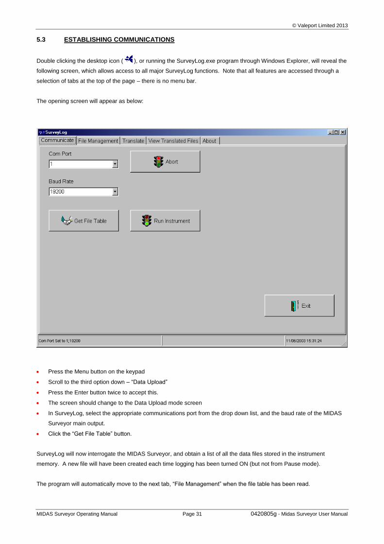
© Valeport Limited 2013
MIDAS Surveyor Operating Manual Page 31 0420805g - Midas Surveyor User Manual
5.3 ESTABLISHING COMMUNICATIONS
Double clicking the desktop icon ( ), or running the SurveyLog.exe program through Windows Explorer, will reveal the
following screen, which allows access to all major SurveyLog functions. Note that all features are accessed through a
selection of tabs at the top of the page – there is no menu bar.
The opening screen will appear as below:
Press the Menu button on the keypad
Scroll to the third option down – “Data Upload”
Press the Enter button twice to accept this.
The screen should change to the Data Upload mode screen
In SurveyLog, select the appropriate communications port from the drop down list, and the baud rate of the MIDAS
Surveyor main output.
Click the “Get File Table” button.
SurveyLog will now interrogate the MIDAS Surveyor, and obtain a list of all the data files stored in the instrument
memory. A new file will have been created each time logging has been turned ON (but not from Pause mode).
The program will automatically move to the next tab, “File Management” when the file table has been read.
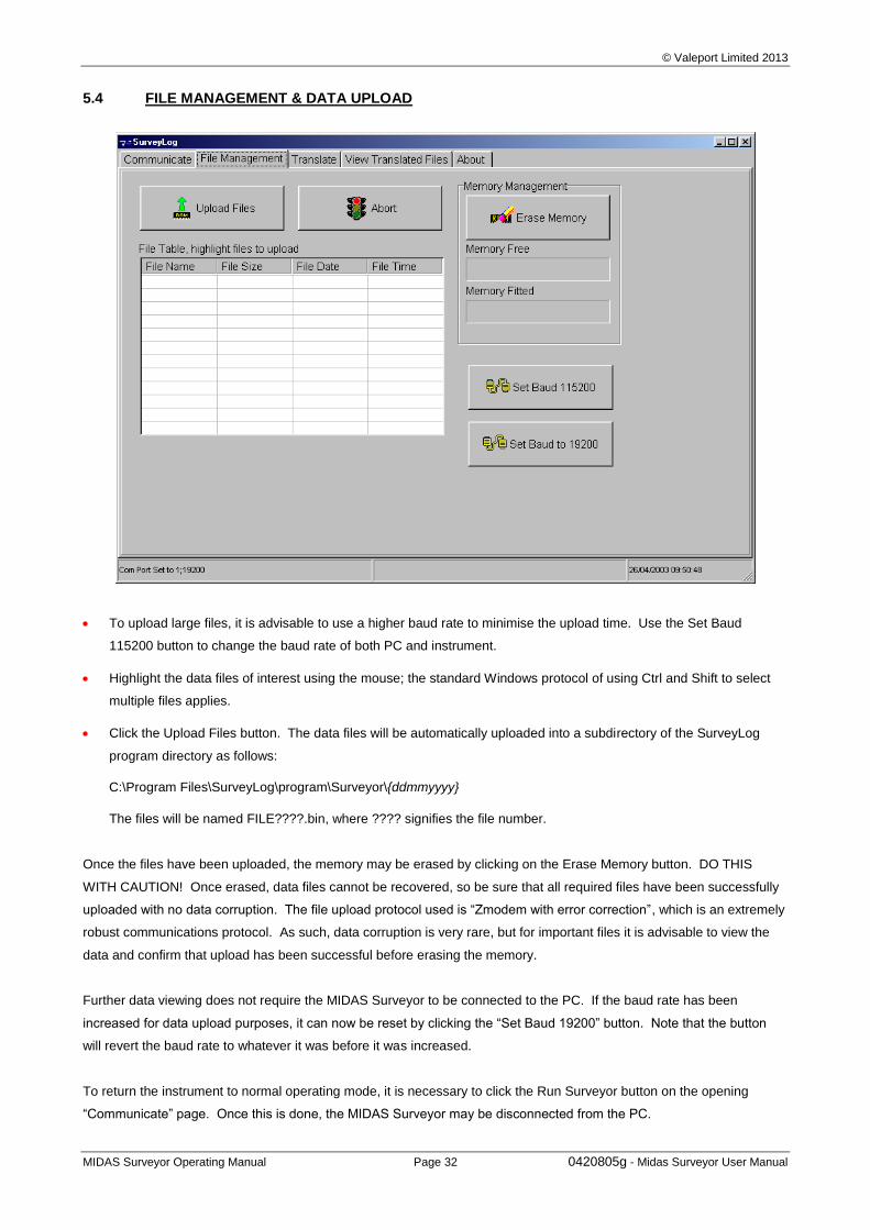
© Valeport Limited 2013
MIDAS Surveyor Operating Manual Page 32 0420805g - Midas Surveyor User Manual
5.4 FILE MANAGEMENT & DATA UPLOAD
To upload large files, it is advisable to use a higher baud rate to minimise the upload time. Use the Set Baud
115200 button to change the baud rate of both PC and instrument.
Highlight the data files of interest using the mouse; the standard Windows protocol of using Ctrl and Shift to select
multiple files applies.
Click the Upload Files button. The data files will be automatically uploaded into a subdirectory of the SurveyLog
program directory as follows:
C:\Program Files\SurveyLog\program\Surveyor\{ddmmyyyy}
The files will be named FILE????.bin, where ???? signifies the file number.
Once the files have been uploaded, the memory may be erased by clicking on the Erase Memory button. DO THIS
WITH CAUTION! Once erased, data files cannot be recovered, so be sure that all required files have been successfully
uploaded with no data corruption. The file upload protocol used is “Zmodem with error correction”, which is an extremely
robust communications protocol. As such, data corruption is very rare, but for important files it is advisable to view the
data and confirm that upload has been successful before erasing the memory.
Further data viewing does not require the MIDAS Surveyor to be connected to the PC. If the baud rate has been
increased for data upload purposes, it can now be reset by clicking the “Set Baud 19200” button. Note that the button
will revert the baud rate to whatever it was before it was increased.
To return the instrument to normal operating mode, it is necessary to click the Run Surveyor button on the opening
“Communicate” page. Once this is done, the MIDAS Surveyor may be disconnected from the PC.
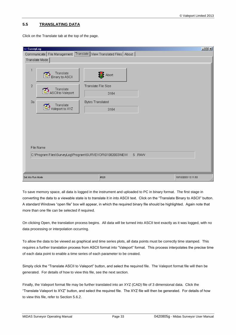
© Valeport Limited 2013
MIDAS Surveyor Operating Manual Page 33 0420805g - Midas Surveyor User Manual
5.5 TRANSLATING DATA
Click on the Translate tab at the top of the page.
To save memory space, all data is logged in the instrument and uploaded to PC in binary format. The first stage in
converting the data to a viewable state is to translate it in into ASCII text. Click on the “Translate Binary to ASCII” button.
A standard Windows “open file” box will appear, in which the required binary file should be highlighted. Again note that
more than one file can be selected if required.
On clicking Open, the translation process begins. All data will be turned into ASCII text exactly as it was logged, with no
data processing or interpolation occurring.
To allow the data to be viewed as graphical and time series plots, all data points must be correctly time stamped. This
requires a further translation process from ASCII format into “Valeport” format. This process interpolates the precise time
of each data point to enable a time series of each parameter to be created.
Simply click the “Translate ASCII to Valeport” button, and select the required file. The Valeport format file will then be
generated. For details of how to view this file, see the next section.
Finally, the Valeport format file may be further translated into an XYZ (CAD) file of 3 dimensional data. Click the
“Translate Valeport to XYZ” button, and select the required file. The XYZ file will then be generated. For details of how
to view this file, refer to Section 5.6.2.
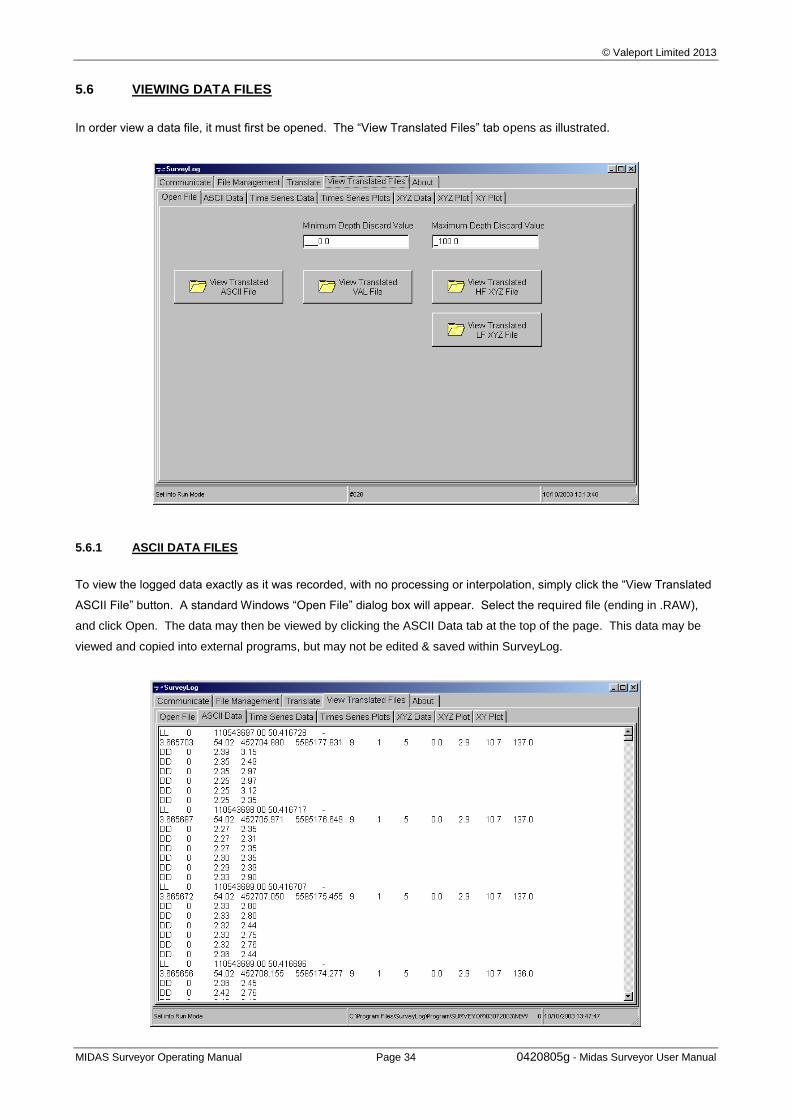
© Valeport Limited 2013
MIDAS Surveyor Operating Manual Page 34 0420805g - Midas Surveyor User Manual
5.6 VIEWING DATA FILES
In order view a data file, it must first be opened. The “View Translated Files” tab opens as illustrated.
5.6.1 ASCII DATA FILES
To view the logged data exactly as it was recorded, with no processing or interpolation, simply click the “View Translated
ASCII File” button. A standard Windows “Open File” dialog box will appear. Select the required file (ending in .RAW),
and click Open. The data may then be viewed by clicking the ASCII Data tab at the top of the page. This data may be
viewed and copied into external programs, but may not be edited & saved within SurveyLog.
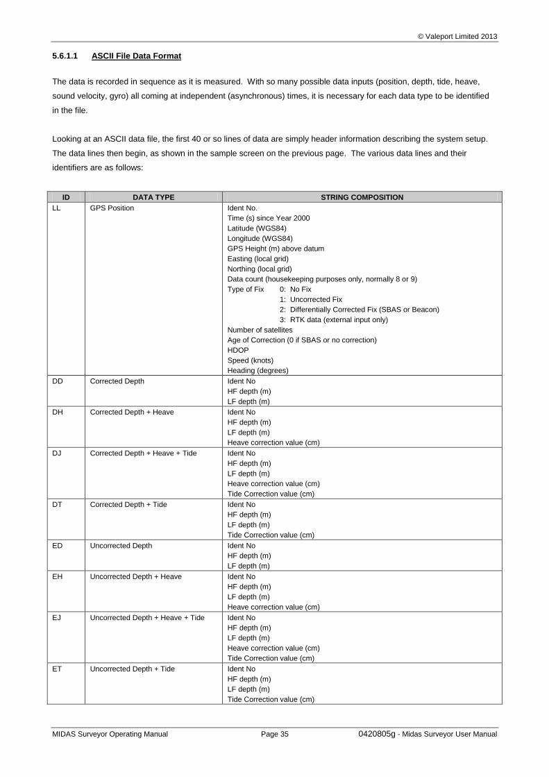
© Valeport Limited 2013
MIDAS Surveyor Operating Manual Page 35 0420805g - Midas Surveyor User Manual
5.6.1.1 ASCII File Data Format
The data is recorded in sequence as it is measured. With so many possible data inputs (position, depth, tide, heave,
sound velocity, gyro) all coming at independent (asynchronous) times, it is necessary for each data type to be identified
in the file.
Looking at an ASCII data file, the first 40 or so lines of data are simply header information describing the system setup.
The data lines then begin, as shown in the sample screen on the previous page. The various data lines and their
identifiers are as follows:
ID DATA TYPE STRING COMPOSITION
LL GPS Position Ident No.
Time (s) since Year 2000
Latitude (WGS84)
Longitude (WGS84)
GPS Height (m) above datum
Easting (local grid)
Northing (local grid)
Data count (housekeeping purposes only, normally 8 or 9)
Type of Fix 0: No Fix
1: Uncorrected Fix
2: Differentially Corrected Fix (SBAS or Beacon)
3: RTK data (external input only)
Number of satellites
Age of Correction (0 if SBAS or no correction)
HDOP
Speed (knots)
Heading (degrees)
DD Corrected Depth Ident No
HF depth (m)
LF depth (m)
DH Corrected Depth + Heave Ident No
HF depth (m)
LF depth (m)
Heave correction value (cm)
DJ Corrected Depth + Heave + Tide Ident No
HF depth (m)
LF depth (m)
Heave correction value (cm)
Tide Correction value (cm)
DT Corrected Depth + Tide Ident No
HF depth (m)
LF depth (m)
Tide Correction value (cm)
ED Uncorrected Depth Ident No
HF depth (m)
LF depth (m)
EH Uncorrected Depth + Heave Ident No
HF depth (m)
LF depth (m)
Heave correction value (cm)
EJ Uncorrected Depth + Heave + Tide Ident No
HF depth (m)
LF depth (m)
Heave correction value (cm)
Tide Correction value (cm)
ET Uncorrected Depth + Tide Ident No
HF depth (m)
LF depth (m)
Tide Correction value (cm)
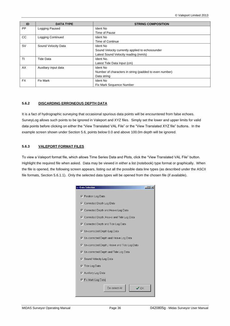
© Valeport Limited 2013
MIDAS Surveyor Operating Manual Page 36 0420805g - Midas Surveyor User Manual
ID DATA TYPE STRING COMPOSITION
PP Logging Paused Ident No
Time of Pause
CC Logging Continued Ident No
Time of Continue
SV Sound Velocity Data Ident No
Sound Velocity currently applied to echosounder
Latest Sound Velocity reading (mm/s)
TI Tide Data Ident No.
Latest Tide Data Input (cm)
AX Auxiliary input data Ident No
Number of characters in string (padded to even number)
Data string
FX Fix Mark Ident No
Fix Mark Sequence Number
5.6.2 DISCARDING ERRONEOUS DEPTH DATA
It is a fact of hydrographic surveying that occasional spurious data points will be encountered from false echoes.
SurveyLog allows such points to be ignored in Valeport and XYZ files. Simply set the lower and upper limits for valid
data points before clicking on either the “View Translated VAL File” or the “View Translated XYZ file” buttons. In the
example screen shown under Section 5.6, points below 0.0 and above 100.0m depth will be ignored.
5.6.3 VALEPORT FORMAT FILES
To view a Valeport format file, which allows Time Series Data and Plots, click the “View Translated VAL File” button.
Highlight the required file when asked. Data may be viewed in either a list (notebook) type format or graphically. When
the file is opened, the following screen appears, listing out all the possible data line types (as described under the ASCII
file formats, Section 5.6.1.1). Only the selected data types will be opened from the chosen file (if available).
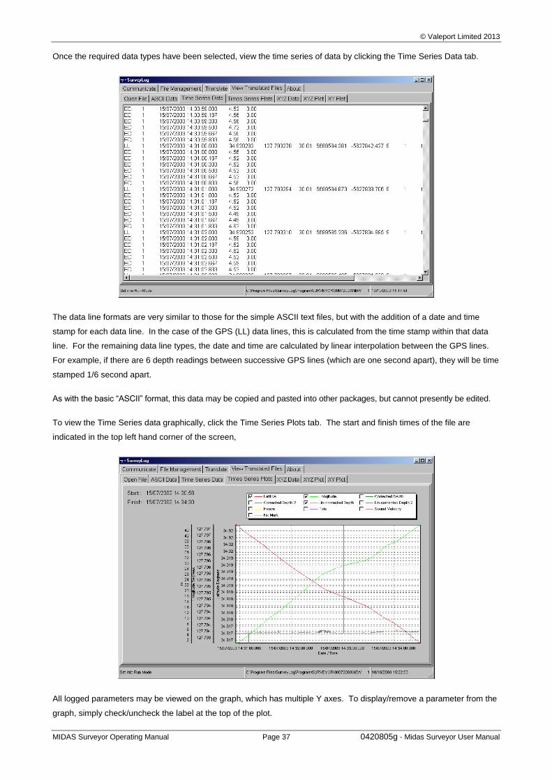
© Valeport Limited 2013
MIDAS Surveyor Operating Manual Page 37 0420805g - Midas Surveyor User Manual
Once the required data types have been selected, view the time series of data by clicking the Time Series Data tab.
The data line formats are very similar to those for the simple ASCII text files, but with the addition of a date and time
stamp for each data line. In the case of the GPS (LL) data lines, this is calculated from the time stamp within that data
line. For the remaining data line types, the date and time are calculated by linear interpolation between the GPS lines.
For example, if there are 6 depth readings between successive GPS lines (which are one second apart), they will be time
stamped 1/6 second apart.
As with the basic “ASCII” format, this data may be copied and pasted into other packages, but cannot presently be edited.
To view the Time Series data graphically, click the Time Series Plots tab. The start and finish times of the file are
indicated in the top left hand corner of the screen,
All logged parameters may be viewed on the graph, which has multiple Y axes. To display/remove a parameter from the
graph, simply check/uncheck the label at the top of the plot.
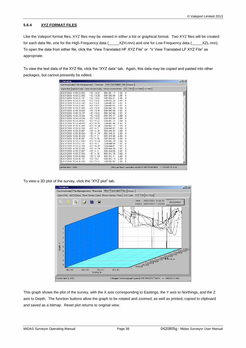
© Valeport Limited 2013
MIDAS Surveyor Operating Manual Page 38 0420805g - Midas Surveyor User Manual
5.6.4 XYZ FORMAT FILES
Like the Valeport format files, XYZ files may be viewed in either a list or graphical format. Two XYZ files will be created
for each data file, one for the High Frequency data (_____XZH.nnn) and one for Low Frequency data (_____XZL.nnn).
To open the data from either file, click the “View Translated HF XYZ File” or “V View Translated LF XYZ File” as
appropriate.
To view the text data of the XYZ file, click the “XYZ data“ tab. Again, this data may be copied and pasted into other
packages, but cannot presently be edited.
To view a 3D plot of the survey, click the “XYZ plot” tab.
This graph shows the plot of the survey, with the X axis corresponding to Eastings, the Y axis to Northings, and the Z
axis to Depth. The function buttons allow the graph to be rotated and zoomed, as well as printed, copied to clipboard
and saved as a bitmap. Reset plot returns to original view.
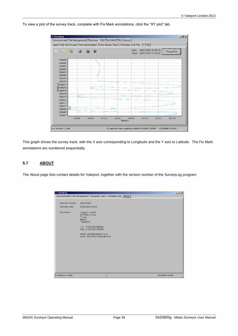
© Valeport Limited 2013
MIDAS Surveyor Operating Manual Page 39 0420805g - Midas Surveyor User Manual
To view a plot of the survey track, complete with Fix Mark annotations, click the “XY plot” tab.
This graph shows the survey track, with the X axis corresponding to Longitude and the Y axis to Latitude. The Fix Mark
annotations are numbered sequentially.
5.7 ABOUT
The About page lists contact details for Valeport, together with the version number of the SurveyLog program:
© Valeport Limited 2013
MIDAS Surveyor Operating Manual Page 40 0420805g - Midas Surveyor User Manual
6 WIRING SCHEDULES
The following pages contain cableforms as detailed below:
0420WO.C00 Midas Surveyor cableform Layout
0420C08 - Echo Sounder Line Connector to Junction Box
0420C09 - Echo Sounder 33KHz Transducer to Junction Box
0420C10 - Echo Sounder 210KHz Transducer to Junction Box
0420C11 - External Power / Charger Lead
0420C12 - External Instrument RS232 Comms Lead
0420C13 – Standard RS232 Data output / PC Comms Lead
0420C14 - Fix Mark Lead
0420C16 - Marine Beacon Line Connector to Junction Box
0420C17 - Marine Beacon to Junction Box
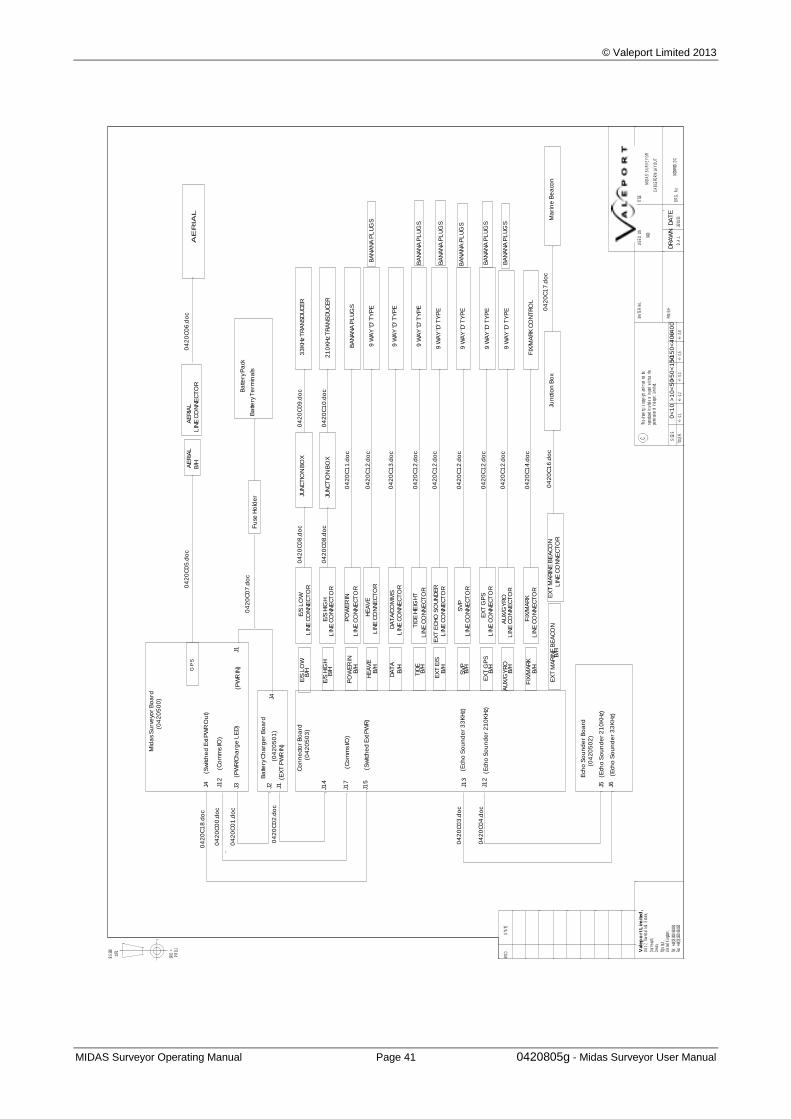
© Valeport Limited 2013
MIDAS Surveyor Operating Manual Page 41 0420805g - Midas Surveyor User Manual
BS
308
:197
2
PR
OJ.
3RD
<
STA
TEM
OD V
ale
po
rt L
imited
,U
nit
7, T
owns
tal
Ind.
Est
ate,
Dar
t mou
t h,
Dev
on,
TQ6
9LX
,U
nit e
d K
i ngd
om.
Tel :
+44
( 0) 1
803
8340
31Fa
x: +
44(0
)180
3 83
4320
CTh
is d
raw
ing
is c
opyr
ight
and
mus
t no
t be
repr
oduc
ed i
n w
hole
or
in p
art
wit
hout
the
perm
issi
on o
f V
alep
ort
Lim
ited
.
SIZ
ES
TOLE
R.
+/-
0.1
+/-
0.2
+/-
0.3
+/-
0.5
+/-
0.8
>1
50
<4
00
0<
10
>1
0<
50>
50
<1
50
>4
00
MA
TER
IAL
FIN
ISH
US
ED
ON
DR
AW
ND
AT
E
TITL
E
DR
G.
No.
D.A
.L26
/11/
0304
20W
00D
.DC
0420
MID
AS
SU
RV
EY
OR
CA
BLE
FOR
M L
AY
OU
T
04
20
C0
0.d
oc
Mid
as
Su
rve
yor
Bo
ard
Ba
ttery
Pa
ck
(04
20
50
0)
(04
20
50
2)
Ech
o S
ou
nd
er
Bo
ard
(04
20
50
3)
Co
nn
ect
or
Bo
ard
(04
20
50
1)
Ba
ttery
Ch
arg
er
Bo
ard
J1
J12
Ba
ttery
Te
rmin
als
J14
J17
J4
J1 J12
J5J13
J6J2J3
AE
RIA
LA
ER
IAL
LIN
E C
ON
NE
CT
OR
AE
RIA
LG
PS
33
KH
z T
RA
NS
DU
CE
RL
INE
CO
NN
EC
TO
R
LIN
E C
ON
NE
CT
OR
BA
NA
NA
PL
UG
SP
OW
ER
INL
INE
CO
NN
EC
TO
R
PO
WE
R IN
9 W
AY
'D' T
YP
EH
EA
VE
LIN
E C
ON
NE
CT
OR
HE
AV
E
DA
TA
LIN
E C
ON
NE
CT
OR
DA
TA
/CO
MM
S
TID
EL
INE
CO
NN
EC
TO
R
TID
E H
EIG
HT
EX
T E
/SL
INE
CO
NN
EC
TO
R
EX
T E
CH
O S
OU
ND
ER
SV
PL
INE
CO
NN
EC
TO
R
SV
P
B/H
EX
T G
PS
EX
T G
PS
AU
X/G
YR
OA
UX
/GY
RO
FIX
/MA
RK
FIX
/MA
RK
E/S
LO
W
E/S
HIG
H
B/H B/H B/H
B/H
B/H
B/H
B/H
B/H
B/H
B/H
B/H
E/S
LO
W
E/S
HIG
H
LIN
E C
ON
NE
CT
OR
LIN
E C
ON
NE
CT
OR
LIN
E C
ON
NE
CT
OR
JUN
CT
ION
BO
X
JUN
CT
ION
BO
X2
10
KH
z T
RA
NS
DU
CE
R
FIX
/MA
RK
CO
NT
RO
L
9 W
AY
'D' T
YP
E
9 W
AY
'D' T
YP
E
9 W
AY
'D' T
YP
E
9 W
AY
'D' T
YP
E
9 W
AY
'D' T
YP
E
9 W
AY
'D' T
YP
E
04
20
C0
1.d
oc
04
20
C0
2.d
oc
04
20
C0
5.d
oc
04
20
C0
6.d
oc
04
20
C0
7.d
oc
04
20
C0
8.d
oc
04
20
C0
8.d
oc
04
20
C1
1.d
oc
04
20
C1
2.d
oc
04
20
C1
3.d
oc
04
20
C1
2.d
oc
04
20
C1
2.d
oc
04
20
C1
2.d
oc
04
20
C1
2.d
oc
04
20
C1
4.d
oc
04
20
C0
9.d
oc
04
20
C1
0.d
oc
04
20
C0
3.d
oc
04
20
C0
4.d
oc
(Co
mm
s I/O
)
(PW
R/C
ha
rge
LE
D)
(PW
R IN
)
(EX
T P
WR
IN)
(Ech
o S
ou
nd
er
33
KH
z)
(Ech
o S
ou
nd
er
21
0K
Hz)
(Ech
o S
ou
nd
er
33
KH
z)
(Ech
o S
ou
nd
er
21
0K
Hz)
(Co
mm
s I/O
)
04
20
C1
2.d
oc
EX
T M
AR
INE
BE
AC
ON
B/H
EX
T M
AR
INE
BE
AC
ON
Ma
rin
e B
ea
con
04
20
C1
6.d
oc
LIN
E C
ON
NE
CT
OR
04
20
C1
8.d
oc
J4 J15
(Sw
itch
ed
Ext
PW
R)
(Sw
itch
ed
Ext
PW
R O
ut)
Fu
se H
old
er
BA
NA
NA
PL
UG
S
BA
NA
NA
PL
UG
S
BA
NA
NA
PL
UG
S
BA
NA
NA
PL
UG
S
BA
NA
NA
PL
UG
S
BA
NA
NA
PL
UG
S
Jun
ctio
n B
ox
04
20
C1
7.d
oc
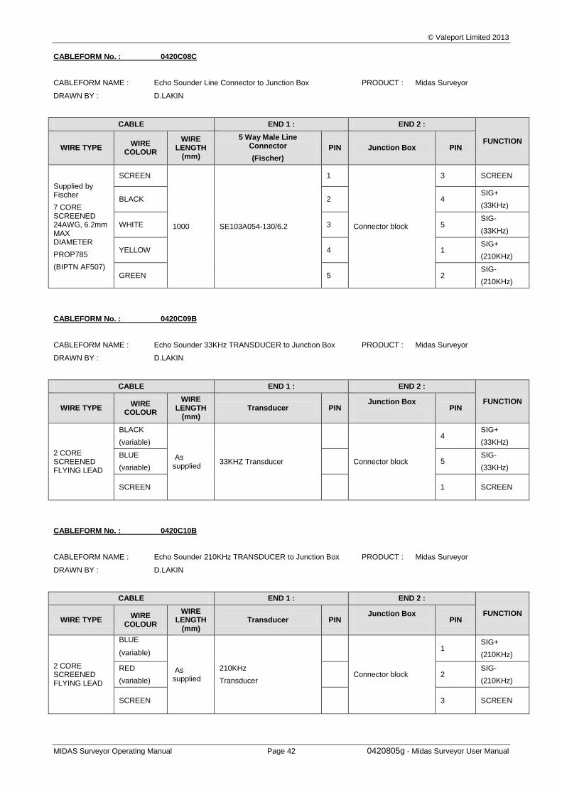
© Valeport Limited 2013
MIDAS Surveyor Operating Manual Page 42 0420805g - Midas Surveyor User Manual
CABLEFORM No. : 0420C08C
CABLEFORM NAME : Echo Sounder Line Connector to Junction Box PRODUCT : Midas Surveyor
DRAWN BY : D.LAKIN
CABLE END 1 : END 2 :
FUNCTION WIRE TYPE
WIRE COLOUR
WIRE LENGTH
(mm)
5 Way Male Line Connector
(Fischer)
PIN Junction Box PIN
Supplied by Fischer
7 CORE SCREENED 24AWG, 6.2mm MAX DIAMETER
PROP785
(BIPTN AF507)
SCREEN
1000 SE103A054-130/6.2
1
Connector block
3 SCREEN
BLACK 2 4 SIG+
(33KHz)
WHITE 3 5 SIG-
(33KHz)
YELLOW 4 1 SIG+
(210KHz)
GREEN 5 2 SIG-
(210KHz)
CABLEFORM No. : 0420C09B
CABLEFORM NAME : Echo Sounder 33KHz TRANSDUCER to Junction Box PRODUCT : Midas Surveyor
DRAWN BY : D.LAKIN
CABLE END 1 : END 2 :
FUNCTION WIRE TYPE
WIRE COLOUR
WIRE LENGTH
(mm) Transducer PIN
Junction Box
PIN
2 CORE SCREENED FLYING LEAD
BLACK
(variable)
As supplied
33KHZ Transducer
Connector block
4 SIG+
(33KHz)
BLUE
(variable) 5
SIG-
(33KHz)
SCREEN 1 SCREEN
CABLEFORM No. : 0420C10B
CABLEFORM NAME : Echo Sounder 210KHz TRANSDUCER to Junction Box PRODUCT : Midas Surveyor
DRAWN BY : D.LAKIN
CABLE END 1 : END 2 :
FUNCTION WIRE TYPE
WIRE COLOUR
WIRE LENGTH
(mm) Transducer PIN
Junction Box
PIN
2 CORE SCREENED FLYING LEAD
BLUE
(variable)
As supplied
210KHz
Transducer
Connector block
1 SIG+
(210KHz)
RED
(variable) 2
SIG-
(210KHz)
SCREEN 3 SCREEN
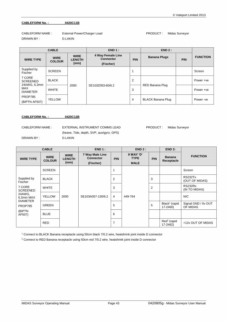
© Valeport Limited 2013
MIDAS Surveyor Operating Manual Page 43 0420805g - Midas Surveyor User Manual
CABLEFORM No. : 0420C11B
CABLEFORM NAME : External Power/Charger Lead PRODUCT : Midas Surveyor
DRAWN BY : D.LAKIN
CABLE END 1 : END 2 :
FUNCTION WIRE TYPE
WIRE COLOUR
WIRE LENGTH
(mm)
4 Way Female Line Connector
(Fischer)
PIN Banana Plugs
PIN
Supplied by Fischer
7 CORE SCREENED 24AWG, 6.2mm MAX DIAMETER
PROP785
(BIPTN AF507)
SCREEN
2000 SE103Z053-60/6.2
1 Screen
BLACK 2
RED Banana Plug
Power +ve
WHITE 3 Power +ve
YELLOW 4 BLACK Banana Plug Power -ve
CABLEFORM No. : 0420C12B
CABLEFORM NAME : EXTERNAL INSTRUMENT COMMS LEAD PRODUCT : Midas Surveyor
(heave, Tide, depth, SVP, aux/gyro, GPS)
DRAWN BY : D.LAKIN
CABLE END 1 : END 2 : END 3:
FUNCTION WIRE TYPE
WIRE COLOUR
WIRE LENGTH
(mm)
7 Way Male Line Connector
(Fischer)
PIN
9 WAY ‘D’ TYPE
MALE
PIN Banana
Receptacle
Supplied by Fischer
7 CORE SCREENED 24AWG, 6.2mm MAX DIAMETER
PROP785
(BIPTN AF507)
SCREEN
2000 SE103A057-130/6.2
1
449-764
Screen
BLACK 2 3 RS232Tx (OUT OF MIDAS)
WHITE 3 2 RS232Rx (IN TO MIDAS)
YELLOW 4 N/C
GREEN 5 5 Black1 (rapid 17-2460)
Signal GND / 0v OUT OF MIDAS
BLUE 6
RED 7 Red2 (rapid 17-2462)
+12v OUT OF MIDAS
1 Connect to BLACK Banana receptacle using 50cm black 7/0.2 wire, heatshrink joint inside D connector
2 Connect to RED Banana receptacle using 50cm red 7/0.2 wire, heatshrink joint inside D connector
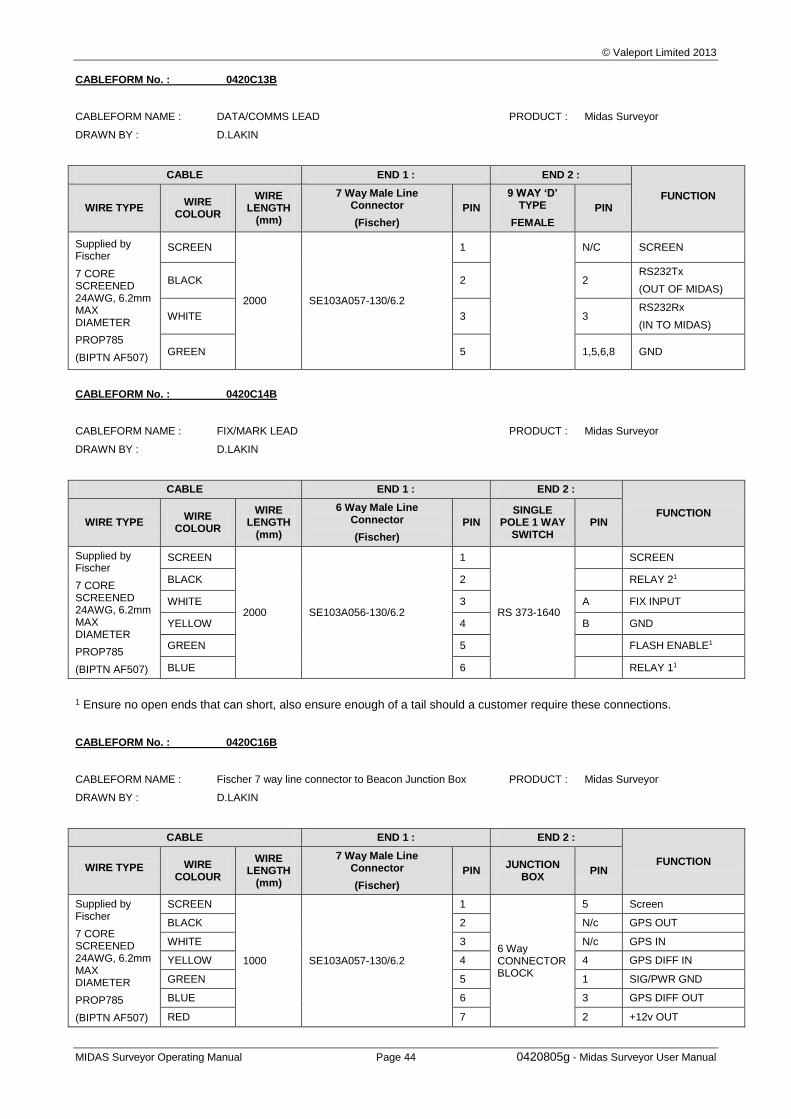
© Valeport Limited 2013
MIDAS Surveyor Operating Manual Page 44 0420805g - Midas Surveyor User Manual
CABLEFORM No. : 0420C13B
CABLEFORM NAME : DATA/COMMS LEAD PRODUCT : Midas Surveyor
DRAWN BY : D.LAKIN
CABLE END 1 : END 2 :
FUNCTION WIRE TYPE
WIRE COLOUR
WIRE LENGTH
(mm)
7 Way Male Line Connector
(Fischer)
PIN
9 WAY ‘D’ TYPE
FEMALE
PIN
Supplied by Fischer
7 CORE SCREENED 24AWG, 6.2mm MAX DIAMETER
PROP785
(BIPTN AF507)
SCREEN
2000 SE103A057-130/6.2
1
N/C SCREEN
BLACK 2 2 RS232Tx
(OUT OF MIDAS)
WHITE 3 3 RS232Rx
(IN TO MIDAS)
GREEN 5 1,5,6,8 GND
CABLEFORM No. : 0420C14B
CABLEFORM NAME : FIX/MARK LEAD PRODUCT : Midas Surveyor
DRAWN BY : D.LAKIN
CABLE END 1 : END 2 :
FUNCTION WIRE TYPE
WIRE COLOUR
WIRE LENGTH
(mm)
6 Way Male Line Connector
(Fischer)
PIN SINGLE
POLE 1 WAY SWITCH
PIN
Supplied by Fischer
7 CORE SCREENED 24AWG, 6.2mm MAX DIAMETER
PROP785
(BIPTN AF507)
SCREEN
2000 SE103A056-130/6.2
1
RS 373-1640
SCREEN
BLACK 2 RELAY 21
WHITE 3 A FIX INPUT
YELLOW 4 B GND
GREEN 5 FLASH ENABLE1
BLUE 6 RELAY 11
1 Ensure no open ends that can short, also ensure enough of a tail should a customer require these connections.
CABLEFORM No. : 0420C16B
CABLEFORM NAME : Fischer 7 way line connector to Beacon Junction Box PRODUCT : Midas Surveyor
DRAWN BY : D.LAKIN
CABLE END 1 : END 2 :
FUNCTION WIRE TYPE WIRE
COLOUR
WIRE LENGTH
(mm)
7 Way Male Line Connector
(Fischer)
PIN JUNCTION
BOX PIN
Supplied by Fischer
7 CORE SCREENED 24AWG, 6.2mm MAX DIAMETER
PROP785
(BIPTN AF507)
SCREEN
1000 SE103A057-130/6.2
1
6 Way CONNECTOR BLOCK
5 Screen
BLACK 2 N/c GPS OUT
WHITE 3 N/c GPS IN
YELLOW 4 4 GPS DIFF IN
GREEN 5 1 SIG/PWR GND
BLUE 6 3 GPS DIFF OUT
RED 7 2 +12v OUT
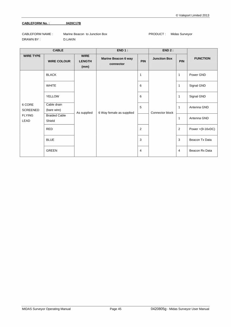
© Valeport Limited 2013
MIDAS Surveyor Operating Manual Page 45 0420805g - Midas Surveyor User Manual
CABLEFORM No. : 0420C17B
CABLEFORM NAME : Marine Beacon to Junction Box PRODUCT : Midas Surveyor
DRAWN BY : D.LAKIN
CABLE END 1 : END 2 :
FUNCTION WIRE TYPE
WIRE COLOUR
WIRE
LENGTH
(mm)
Marine Beacon 6 way
connector PIN
Junction Box
PIN
6 CORE
SCREENED
FLYING
LEAD
BLACK
As supplied 6 Way female as supplied
1
Connector block
1 Power GND
WHITE 6 1 Signal GND
YELLOW 6 1 Signal GND
Cable drain
(bare wire) 5 1 Antenna GND
Braided Cable
Shield 1 Antenna GND
RED 2 2 Power +(9-16vDC)
BLUE 3 3 Beacon Tx Data
GREEN 4 4 Beacon Rx Data