Valeport Limited Valeport Limited Tide Gauge MODEL 710 & Receivers Installation & Operation Manual Document Ref: 0710853f.doc Date January 2003 This confidential document was prepared by the staff of Valeport Limited, the Company, and is the property of the Company, which also owns the copyright therein. All rights conferred by the law of the copyright and by virtue of international copyright conventions are reserved to the Company. This document must not be copied, reprinted or reproduced in any material form, either wholly or in part, and the contents of this document, and any method or technique available therefrom, must not be disclosed to any other person whatsoever without the prior written consent of the Company. Valeport Limited, Tel: +44 (0)1803 869292 St Peters Quay , Fax: +44 (0)1803 869293 TOTNES, e-mail: [email protected] Devon, TQ9 5EW, Web; www.valeport.co.uk UK As part of our policy of continuous development, we reserve the right to alter, without prior notice, all specifications, designs, prices and conditions of supply for all our equipment. Copyright 2003 MODEL 710 Manual 1 0710853f.doc

Welcome message from author
This document is posted to help you gain knowledge. Please leave a comment to let me know what you think about it! Share it to your friends and learn new things together.
Transcript
Valeport Limited
Valeport Limited Tide Gauge MODEL 710 & Receivers
Installation & Operation Manual Document Ref: 0710853f.doc Date January 2003 This confidential document was prepared by the staff of Valeport Limited, the Company, and is the property of the Company, which also owns the copyright therein. All rights conferred by the law of the copyright and by virtue of international copyright conventions are reserved to the Company. This document must not be copied, reprinted or reproduced in any material form, either wholly or in part, and the contents of this document, and any method or technique available therefrom, must not be disclosed to any other person whatsoever without the prior written consent of the Company. Valeport Limited, Tel: +44 (0)1803 869292 St Peters Quay , Fax: +44 (0)1803 869293 TOTNES, e-mail: [email protected] Devon, TQ9 5EW, Web; www.valeport.co.uk UK As part of our policy of continuous development, we reserve the right to alter, without prior notice, all specifications, designs, prices and conditions of supply for all our equipment. Copyright 2003
MODEL 710 Manual 1 0710853f.doc

Valeport Limited
CONTENTS PAGE
1 INTRODUCTION ........................................................................................................................................................ 4 1.1 General Description ...................................................................................................................................... 4 1.2 Measurement Method.................................................................................................................................... 4 1.3 Calibration..................................................................................................................................................... 4 1.4 Equipment Supplied ...................................................................................................................................... 4 1.5 Service Contact ............................................................................................................................................. 5
2 SYSTEM DESCRIPTION............................................................................................................................................ 6 2.1 Transducer..................................................................................................................................................... 6 2.2 Gauging Station............................................................................................................................................. 6 2.3 MEMORY..................................................................................................................................................... 6 2.4 Remote LCD Receiving Station .................................................................................................................... 6 2.5 Remote standard Receiving Station .............................................................................................................. 7 2.6 Data Telemetry.............................................................................................................................................. 8
3 INSTALLATION ......................................................................................................................................................... 9 3.1 Transducer..................................................................................................................................................... 9 3.2 Deployment................................................................................................................................................... 9
3.2.1 Slide Wire to Weight ..................................................................................................................... 9 3.2.2 Slide Wire and Bottom Mounting Plate......................................................................................... 9 3.2.3 Bottom Mounting Plate Only......................................................................................................... 9
3.3 Gauging Station............................................................................................................................................. 10 3.3.1 Transducer\Meteorological sensors wiring schedules.................................................................... 11 3.3.2 Initalising the 710 Tide Gauge ...................................................................................................... 13
3.4 Radio Links ................................................................................................................................................... 13
4 CONFIGURATION...................................................................................................................................................... 14 4.1 Setup ............................................................................................................................................................. 14
4.1.1 Set Clock ....................................................................................................................................... 14 4.1.2 METRES ....................................................................................................................................... 15 4.1.3 M/S ................................................................................................................................................ 15 4.1.4 CALIBRATED.............................................................................................................................. 15 4.1.5 Transmit Sync................................................................................................................................ 15
4.2 DEFAULTS .................................................................................................................................................. 15 4.3 CALIBRATION............................................................................................................................................ 17
4.3.1 Datum Offset ................................................................................................................................. 17 4.3.2 Range Calibration .......................................................................................................................... 19
4.4 ERASE MEMORY ....................................................................................................................................... 21
5 REMOTE RECEIVING STATION.............................................................................................................................. 22 5.1 Setting up the LCD Tide gauge receiver ....................................................................................................... 22
5.1.1 Reading Serial Number and Software Version .............................................................................. 24 5.1.2 Changing the Local output format ................................................................................................. 24 5.1.3. Changing the Station Display Order .............................................................................................. 25 5.1.4 The analogue Output (Tide only) Option....................................................................................... 25
5.2 Setting up the Standard Tide gauge receiver ................................................................................................. 26 5.2.1 Reading Serial Number and Software Version .............................................................................. 26 5.2.2 Changing the Local output format ................................................................................................. 26
5.3 Radio & Antenna Specifications ................................................................................................................... 27 Specification of Radio Structures FUC-3 Antenna .................................................................................... 27
6 MAINTENANCE ......................................................................................................................................................... 28 6.1 Transducer..................................................................................................................................................... 28 6.2 Gauging Station............................................................................................................................................. 28
MODEL 710 Manual 2 0710853f.doc
Valeport Limited
APPENDIX 1 DRAWINGS .............................................................................................................................................. 29
APPENDIX 2 CALIBRATION......................................................................................................................................... 35
APPENDIX 3 EQUIPMENT SUPPLIED ......................................................................................................................... 39
APPENDIX 4 GUARANTEE CERTIFICATE................................................................................................................. 41
MODEL 710 Manual 3 0710853f.doc
Valeport Limited
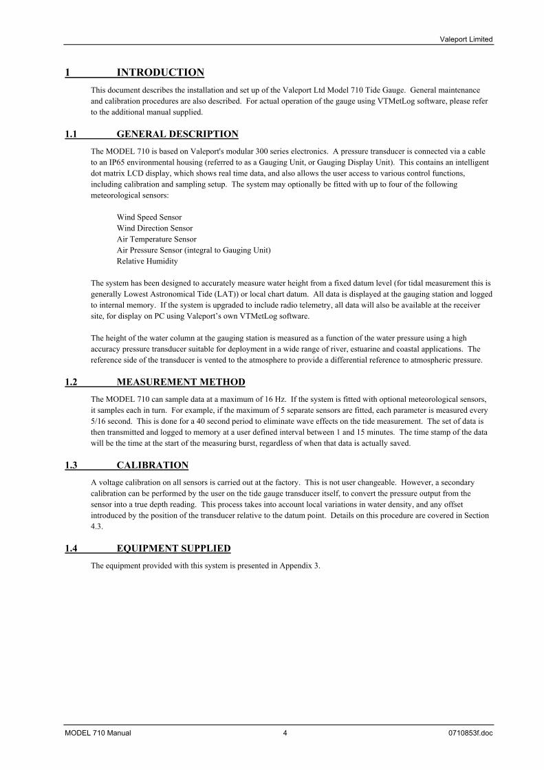
1 INTRODUCTION This document describes the installation and set up of the Valeport Ltd Model 710 Tide Gauge. General maintenance and calibration procedures are also described. For actual operation of the gauge using VTMetLog software, please refer to the additional manual supplied.
1.1 GENERAL DESCRIPTION
The MODEL 710 is based on Valeport's modular 300 series electronics. A pressure transducer is connected via a cable to an IP65 environmental housing (referred to as a Gauging Unit, or Gauging Display Unit). This contains an intelligent dot matrix LCD display, which shows real time data, and also allows the user access to various control functions, including calibration and sampling setup. The system may optionally be fitted with up to four of the following meteorological sensors:
Wind Speed Sensor Wind Direction Sensor Air Temperature Sensor Air Pressure Sensor (integral to Gauging Unit) Relative Humidity
The system has been designed to accurately measure water height from a fixed datum level (for tidal measurement this is generally Lowest Astronomical Tide (LAT)) or local chart datum. All data is displayed at the gauging station and logged to internal memory. If the system is upgraded to include radio telemetry, all data will also be available at the receiver site, for display on PC using Valeport’s own VTMetLog software. The height of the water column at the gauging station is measured as a function of the water pressure using a high accuracy pressure transducer suitable for deployment in a wide range of river, estuarine and coastal applications. The reference side of the transducer is vented to the atmosphere to provide a differential reference to atmospheric pressure.
1.2 MEASUREMENT METHOD
The MODEL 710 can sample data at a maximum of 16 Hz. If the system is fitted with optional meteorological sensors, it samples each in turn. For example, if the maximum of 5 separate sensors are fitted, each parameter is measured every 5/16 second. This is done for a 40 second period to eliminate wave effects on the tide measurement. The set of data is then transmitted and logged to memory at a user defined interval between 1 and 15 minutes. The time stamp of the data will be the time at the start of the measuring burst, regardless of when that data is actually saved.
1.3 CALIBRATION
A voltage calibration on all sensors is carried out at the factory. This is not user changeable. However, a secondary calibration can be performed by the user on the tide gauge transducer itself, to convert the pressure output from the sensor into a true depth reading. This process takes into account local variations in water density, and any offset introduced by the position of the transducer relative to the datum point. Details on this procedure are covered in Section 4.3.
1.4 EQUIPMENT SUPPLIED
The equipment provided with this system is presented in Appendix 3.
MODEL 710 Manual 4 0710853f.doc

Valeport Limited
1.5 SERVICE CONTACT
In the event of encountering problems with the instrument, please contact Valeport on the numbers below: Tel: +44(0)1803 834031 Fax: +44(0)1803 834320 e-mail: [email protected] Valeport will be pleased to advise on the correct course of action.
MODEL 710 Manual 5 0710853f.doc
Valeport Limited
2 SYSTEM DESCRIPTION
2.1 TRANSDUCER
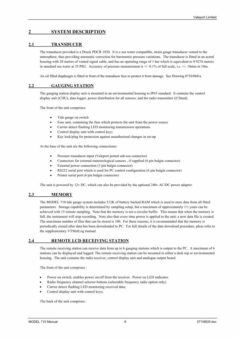
The transducer provided is a Druck PDCR 1830. It is a sea water compatible, strain gauge transducer vented to the atmosphere, thus providing automatic correction for barometric pressure variations. The transducer is fitted in an acetal housing with 20 metres of vented signal cable, and has an operating range of 1 bar which is equivalent to 9.9276 metres in standard sea water at 35 PSU. Accuracy of pressure measurement is +/- 0.1% of full scale, i.e. +/- 10mm in 10m. An oil filled diaphragm is fitted in front of the transducer face to protect it from damage. See Drawing 0710/068/a.
2.2 GAUGING STATION
The gauging station display unit is mounted in an environmental housing to IP65 standard. It contains the control display unit (CDU), data logger, power distribution for all sensors, and the radio transmitter (if fitted). The front of the unit comprises:
Tide gauge on switch • • • • •
• • • • •
Fuse unit, containing the fuse which protects the unit from the power source Carrier detect flashing LED monitoring transmission operations Control display unit with control keys Key lock/plug for protection against unauthorised changes in set-up
At the base of the unit are the following connections:
Pressure transducer input (Valeport potted sub-sea connector) Connectors for external meteorological sensors , if supplied (6 pin bulgin connector) External power connection (3 pin bulgin connector) RS232 serial port which is used for PC control configuration (6 pin bulgin connector) Printer serial port (6 pin bulgin connector)
The unit is powered by 12v DC, which can also be provided by the optional 240v AC/DC power adaptor.
2.3 MEMORY
The MODEL 710 tide gauge system includes 512K of battery backed RAM which is used to store data from all fitted parameters. Storage capability is determined by sampling setup, but a maximum of approximately 1½ years can be achieved with 15 minute sampling. Note that the memory is not a circular buffer. This means that when the memory is full, the instrument will stop recording. Note also that every time power is applied to the unit, a new data file is created. The maximum number of files that can be stored is 100. For these reasons, it is recommended that the memory is periodically erased after data has been downloaded to PC. For full details of the data download procedure, pleas refer to the supplementary VTMetLog manual.
2.4 REMOTE LCD RECEIVING STATION
The remote receiving station can receive data from up to 6 gauging stations which is output to the PC. A maximum of 6 stations can be displayed and logged. The remote receiving station can be mounted in either a desk top or environmental housing. The unit contains the radio receiver, control display unit and analogue output board. The front of the unit comprises :
Power on switch, enables power on/off from the receiver. Power on LED indicator. • • • •
Radio frequency channel selector buttons (selectable frequency radio option only) Carrier detect flashing LED monitoring received data; Control display unit with control keys;
The back of the unit comprises :
MODEL 710 Manual 6 0710853f.doc

Valeport Limited
The desk top version has a RS232 serial port (nine pin female socket) which is used for PC control configuration and printer output,
•
• •
• • •
The desk top version has a RS232 serial port (nine pin female ) which is used to configure the receiver Two 4 way bulkhead Mil spec connector (female) for 500mV and 5V analogue output of the tide height. Calibrated for 0 –5 m tide height. (Analogue option only) 3 way Mil-Spec connector (male) for 12v power in. the aerial connection Fuse unit, containing the fuse which protects the unit from the power source;
The unit can be powered by external 220~240 VAC mains power supply through a 12V adapter.
2.5 REMOTE STANDARD RECEIVING STATION
The remote receiving station can receive data from up to 6 gauging stations which is output to the PC. A maximum of 6 stations can be displayed and logged. The remote receiving station can be mounted in either a desk top or environmental housing. The unit contains the radio receiver and a single RS232 output. The front of the unit comprises :
Carrier detect flashing LED monitoring received data; • • •
• • • •
Power on LED; Radio frequency channel selector switch
The back of the unit comprises :
One RS232 serial outputs (nine pin female socket) for data output to a PC 3 way Mil-Spec connector (male) for 10 to 28vDC power in. the aerial connection Fuse unit, containing the fuse which protects the unit from the power source;
The unit can be powered by external 220~240 VAC mains power supply through a 12V adapter.
MODEL 710 Manual 7 0710853f.doc

Valeport Limited
2.6 DATA TELEMETRY
The Model 710 can be fitted with a selection of data telemetry devices, according to the following table:
Display Device
Allows LED Display
(Tide only) Remote Gauging
Display VTMetLog PC
Display Software Standard Radio Link
Data Telemetry
Bi-directional Radio Link
Data Telemetry, Data Extraction and Gauge Setup
* *
Modem (Land-line)
Data Telemetry, Data Extraction and Gauge Setup
*: Data will be displayed, but extraction and setup are not possible from the remote display station.
Standard Radio Link Uses Magenta MP2518 VHF radios, operating in the bandwidth of 172.1MHz. The radios are supplied fitted (transmitter in the main gauging display unit, receiver in the remote display unit or in a dedicated housing for PC), and come with standard 20m lengths of co-axial signal cable and 3dB omnidirectional aerials. The radios, with clear line of sight, can transmit data over a distance of up to 15km, depending on conditions. Obstructions will reduce this distance. The baud rate of transmission between the radios is 2400. Bi-Directional Radio Link As above, except that instead of a transmitter and receiver, the system is fitted with a transceiver at each end. When used with VTMetLog as the remote display system, this allows the user to communicate with the gauge, altering setup parameters and extracting data. Modem Link The modem link option allows the same functions as the bi-directional radio link, but using a telephone link rather than radio. This system is not compatible with multi-receiver systems. Currently only available as a land-line modem.
MODEL 710 Manual 8 0710853f.doc
Valeport Limited
3 INSTALLATION
3.1 TRANSDUCER
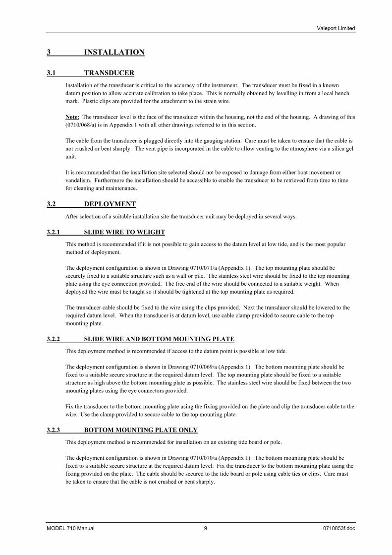
Installation of the transducer is critical to the accuracy of the instrument. The transducer must be fixed in a known datum position to allow accurate calibration to take place. This is normally obtained by levelling in from a local bench mark. Plastic clips are provided for the attachment to the strain wire. Note: The transducer level is the face of the transducer within the housing, not the end of the housing. A drawing of this (0710/068/a) is in Appendix 1 with all other drawings referred to in this section. The cable from the transducer is plugged directly into the gauging station. Care must be taken to ensure that the cable is not crushed or bent sharply. The vent pipe is incorporated in the cable to allow venting to the atmosphere via a silica gel unit. It is recommended that the installation site selected should not be exposed to damage from either boat movement or vandalism. Furthermore the installation should be accessible to enable the transducer to be retrieved from time to time for cleaning and maintenance.
3.2 DEPLOYMENT
After selection of a suitable installation site the transducer unit may be deployed in several ways.
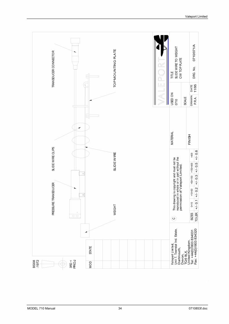
3.2.1 SLIDE WIRE TO WEIGHT
This method is recommended if it is not possible to gain access to the datum level at low tide, and is the most popular method of deployment. The deployment configuration is shown in Drawing 0710/071/a (Appendix 1). The top mounting plate should be securely fixed to a suitable structure such as a wall or pile. The stainless steel wire should be fixed to the top mounting plate using the eye connection provided. The free end of the wire should be connected to a suitable weight. When deployed the wire must be taught so it should be tightened at the top mounting plate as required. The transducer cable should be fixed to the wire using the clips provided. Next the transducer should be lowered to the required datum level. When the transducer is at datum level, use cable clamp provided to secure cable to the top mounting plate.
3.2.2 SLIDE WIRE AND BOTTOM MOUNTING PLATE
This deployment method is recommended if access to the datum point is possible at low tide. The deployment configuration is shown in Drawing 0710/069/a (Appendix 1). The bottom mounting plate should be fixed to a suitable secure structure at the required datum level. The top mounting plate should be fixed to a suitable structure as high above the bottom mounting plate as possible. The stainless steel wire should be fixed between the two mounting plates using the eye connectors provided. Fix the transducer to the bottom mounting plate using the fixing provided on the plate and clip the transducer cable to the wire. Use the clamp provided to secure cable to the top mounting plate.
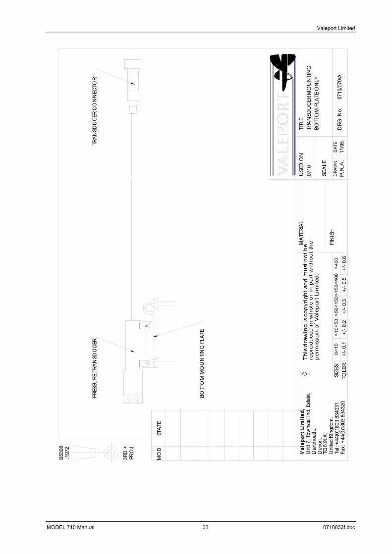
3.2.3 BOTTOM MOUNTING PLATE ONLY
This deployment method is recommended for installation on an existing tide board or pole. The deployment configuration is shown in Drawing 0710/070/a (Appendix 1). The bottom mounting plate should be fixed to a suitable secure structure at the required datum level. Fix the transducer to the bottom mounting plate using the fixing provided on the plate. The cable should be secured to the tide board or pole using cable ties or clips. Care must be taken to ensure that the cable is not crushed or bent sharply.
MODEL 710 Manual 9 0710853f.doc

Valeport Limited
3.3 GAUGING STATION
The gauging unit is provided in an environmental housing which should be securely bolted to a suitable structure. Make sure that all connectors are in their appropriate sockets, as labelled, with the data output cable connected to the socket marked “Local Output”. When using selectable frequency radio transceivers, the data output cable is replaced by a six pin dummy Bulgin connector. This must be fitted to the gauge to allow telemetry of the data. The dummy plug is not needed for operation with fixed frequency radios. If the system is fitted with a radio, it is important to ensure that the aerial is connected before the power is switched on. Failure to do so will result in damage to the radio transmitter.
MODEL 710 Manual 10 0710853f.doc
Valeport Limited
3.3.1 TRANSDUCER\METEOROLOGICAL SENSORS WIRING SCHEDULES
Should it be necessary to remove the Bulgin connectors of the meteorological sensors to connect with a the tide gauge unit inside a building, the connections are as follows:
MODEL 710 Manual 11 0710853f.doc

Valeport Limited
3.3.1.1 TRANSDUCER CABLE/CONNECTOR WIRING SCHEDULES
End 1:- Transducer End 2:- 8 WAY MALE MIL SPEC CONNECTOR Sensor Function Wire
Type Wire colour Pin Connector
‘’ +ve supply Standardcable
Red C 8 WAY MALE MIL SPEC CONNECTOR
‘’ -ve supply ‘’ White E ‘’ + signal out ‘’ Yellow B ‘’ -ve signal ‘’ Blue F‘’ Screen ‘’ Screen (heat shrink wrap) D
Note:- Pin H of the Mil Spec connector is drilled out to allow passage of the venting tube from the transducer cable. Assembly – Potting procedure
1. Slide complete cable connector assembly in sequence onto the cable (sequence as connector supplied assemble). 2. Strip back cable sleeving. Cut inner cores approximately 20mm long. Strip to and tin the wire ends and solder the wires into the buckets of the Mil Spec connector as specified above.
Check cable for continuity. 3. Lightly screw in gland nut onto tapered grommet. This will prevent the potting compound, poured into the housing from insert end, from leaking out the bottom end. Half fill the housing
with potting compound and lightly smear onto the insert thread. Pull the cable back into the housing. The potting will lubricate the grommet and allow the connector housing to turn on the cable. Screw the insert firmly into the front face of the connector, ensuring that it is flush and uncoiling all twists from the connector end of the cable.
4. Screw the gland nut into position until tight. Smear some potting onto the gland nut itself. Pour a small amount into the main boot. Slide boot on to housing and remove any excess potting compound. It may help to insert a small screwdriver in between the cable and the rear of the boot to relieve any internal potting pressure . Excess potting will be expelled from the boot.
5. Allow two hours for the potting to cure. The potting aids in sealing the wires and rear end of the insert creating a water tight seal .
MODEL 710 Manual 12 0710853f.doc
Valeport Limited
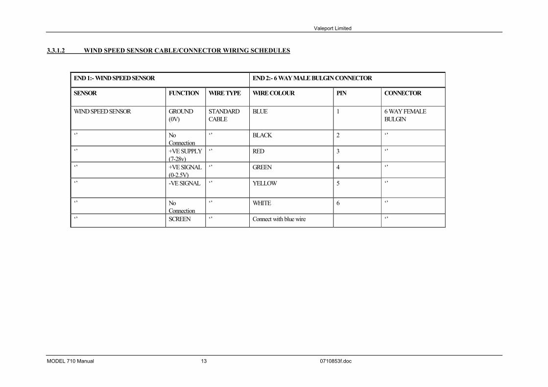
3.3.1.2 WIND SPEED SENSOR CABLE/CONNECTOR WIRING SCHEDULES
END 1:- WIND SPEED SENSOR END 2:- 6 WAY MALE BULGIN CONNECTOR
SENSOR FUNCTION WIRE TYPE WIRE COLOUR PIN CONNECTOR
WIND SPEED SENSOR GROUND(0V)
STANDARDCABLE
BLUE 1 6 WAY FEMALEBULGIN
‘’ NoConnection
‘’ BLACK 2 ‘’
‘’ +VE SUPPLY(7-28v)
‘’ RED 3 ‘’
‘’ +VE SIGNAL(0-2.5V)
‘’ GREEN 4 ‘’
‘’ -VE SIGNAL ‘’ YELLOW 5 ‘’
‘’ NoConnection
‘’ WHITE 6 ‘’
‘’ SCREEN ‘’ Connect with blue wire ‘’
MODEL 710 Manual 13 0710853f.doc
Valeport Limited
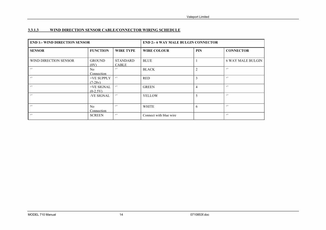
3.3.1.3 WIND DIRECTION SENSOR CABLE/CONNECTOR WIRING SCHEDULE
END 1:- WIND DIRECTION SENSOR END 2:- 6 WAY MALE BULGIN CONNECTOR
SENSOR FUNCTION WIRE TYPE WIRE COLOUR PIN CONNECTOR
WIND DIRECTION SENSOR GROUND(0V)
STANDARDCABLE
BLUE 1 6 WAY MALE BULGIN
‘’ NoConnection
‘’ BLACK 2 ‘’
‘’ +VE SUPPLY(7-28v)
‘’ RED 3 ‘’
‘’ +VE SIGNAL(0-2.5V)
‘’ GREEN 4 ‘’
‘’ -VE SIGNAL ‘’ YELLOW 5 ‘’
‘’ NoConnection
‘’ WHITE 6 ‘’
‘’ SCREEN ‘’ Connect with blue wire ‘’
MODEL 710 Manual 14 0710853f.doc

Valeport Limited
3.3.2 INITALISING THE 710 TIDE GAUGE
Power to the unit is taken from the grey Digital Current Loop box. As soon as power is applied to this, the MODEL 710 Tide Gauge will power up with the following display.
MODEL 710 TIDE/MET GAUGE
VERSION 4.00
VALEPORT LTD 1998
The unit will then automatically enter its Run Mode, displaying the following screen. Data fields will remain blank until the first measuring cycle is complete. File XXX/100 DATE AND TIME TIDE HEIGHT IN METRES PRESS IN mBar) WIND SPEED IN M/S TEMP IN Deg C) WIND DIR IN DEG MAX GUST IN M/S UNITS CALIBRATED/COUNTS Note: Items marked by brackets as follows indicate where data will be displayed. If the system is not installed on site by Valeport Ltd the following factors must be set by the user on installation:
• Set clock, imperative for multi-gauge systems; • Datum offset and/or range calibration at gauging station.
Two methods of user configuration are available: either directly via the control display unit keys or using a PC and VTMetLog software via the local comms port and Digital Current Loop Box. Operation with PC is covered in the supplementary manual – the following pages contain only information on operation via the front control panel of the Gauging Display Station. Functions available using the panel are limited to those necessary for initial set up of the tide gauge. Higher functions must be performed via PC.
3.4 RADIO LINKS
Please ensure that the aerial is connected to the gauge before applying power. Failure to do so may result in damage to the radio. The aerial should be positioned in such a way as to ensure the best visibility to the receiver site. When using bi-directional radio communications, the data output cable is replaced by a six pin dummy Bulgin connector. This must be fitted to the gauge to allow telemetry of the data. Likewise, the receiver aerial should also be positioned so as to offer the best line of sight to the transmitter. The 20m cables may be extended if necessary by using co-axial cable fitted with the appropriate N type connectors. Take note that extending the cable may result in signal losses, and therefore reduced telemetry distance.
MODEL 710 Manual 13 0710853f.doc

Valeport Limited
4 CONFIGURATION To commence configuration the key lock/plug must be inserted into the 9 pin D type socket on the front of the panel. To access the configuration menu hit any button on the control display unit. The following screen will appear:
C D U S E T U P< < < S E T U P C A L I B R A T I O N > > >
< < < D E F A U L T S E R A S E M E M O R Y > > >
< < < 1 9 2 0 0 b a u d (c h a n g e ) E X I T > > >
4.1 SETUP
On pressing the button adjacent to Setup the following will be displayed:
SETUP <<TRANSMIT SYNC xxS CALIBRATED>> <<METRES or FEET SET CLOCK>> <<M/S or KNOTS EXIT>>
4.1.1 SET CLOCK
This option sets the correct time. <<NEXT INCREASE>> TIME: HOURS:MINS EXIT>> DATE: DD/MM/YYYY DECREASE>> Cycle through the date/time with the NEXT key until the parameter that needs changing flashes. Then use the increase and/or decrease buttons to set the correct time and date. It is important that in the case of multi gauge systems the clocks are synchronised, i.e. set accurately, in seconds, to the same time as the clocks on the other gauging stations and the receiving station. Pressing EXIT starts the clock running from HOURS:MINS:00 secs, as set.
MODEL 710 Manual 14 0710853f.doc

Valeport Limited
4.1.2 METRES
Use this button to toggle between the displayed units of tide height, metres or feet. Note that all logged data is recorded as metres, regardless of the units used in the display. Calibration and set up of the transducer will be performed in the units selected here.
4.1.3 M/S
Use this button to toggle between the displayed units of wind speed, metres/second or knots.
4.1.4 CALIBRATED
As standard, the output from the transducer is calibrated, so that the display of tide height will be in metres (or feet). If desired, the unit can be configured so that the data is displayed in raw analogue to digital counts from the transducer.
4.1.5 TRANSMIT SYNC
To avoid data loss in multi-gauge systems, resulting from more than one gauge transmitting data at the same time, it is possible to set a small offset in the data transmission time of each unit. For example, in a 3 gauge system, there may be 1 gauge transmitting every 60 seconds, 1 every 59 seconds, and 1 every 58 seconds. In this way, transmission clashes are minimised. The transmit sync is increased by 1 second, every time the button is pushed, up to a maximum of 20 seconds. The value of the transmit sync is the number of seconds less than a full minute that the gauge will transmit data at. For example, a gauge set to transmit data at 10 minute intervals with a 5 second transmit sync will actually transmit every 9 minutes 55 seconds. For a single gauge system, the transmit sync should be set to zero. Press the EXIT button to return to the main CDU setup menu.
4.2 DEFAULTS
This button is used to set up the interval for transmission and data logging, and also the gauge identification number.
D E F A U L T S< < < T X T I M E + T X T E S T > > >
< < < T X T I M E -
< < < S T A T I O N I D = 0 0 E X I T > > >
Use the TX TIME +/- keys to increase or decrease the transmission timing interval. The interval can be set to any whole number of minutes between 1 and 15. Check also that the Transmit Sync function is correctly set (Section 4.1.5). This interval is also the interval at which data is logged in the unit’s memory. The Station ID is a number assigned to each gauge, and referred to in multi-gauge systems. It must also be set in single gauge systems, although in this case there is no need to alter the factory default setting of ‘01’. Pressing the adjacent button increases the ID number up to a maximum of ‘50’ (after which it returns to ‘01’). The TX test function transmits a continuous stream of data from the tide gauge unit. This function can be used in two capacities:- By running the TX test function to continuously output data to a PC the baud rate of the tide gauge can be established (should this be changed or forgotten). Connect the unit ,via the local output and data extraction lead, to a terminal emulation program. By setting the term program to different baud rate (600,1200, 2400, 4800, 9600 or 19200) and systemically scanning through these, the baud rate is identified by comprehendable data being returned on the screen.
MODEL 710 Manual 15 0710853f.doc
Valeport Limited
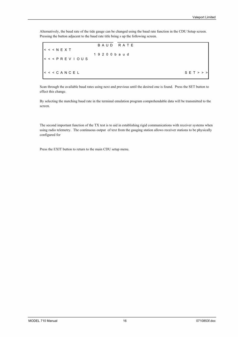
Alternatively, the baud rate of the tide gauge can be changed using the baud rate function in the CDU Setup screen. Pressing the button adjacent to the baud rate title bring s up the following screen.
B A U D R A T E< < < N E X T
1 9 2 0 0 b a u d< < < P R E V I O U S
< < < C A N C E L S E T > > >
Scan through the available baud rates using next and previous until the desired one is found. Press the SET button to effect this change. By selecting the matching baud rate in the terminal emulation program comprehendable data will be transmitted to the screen. The second important function of the TX test is to aid in establishing rigid communications with receiver systems when using radio telemetry. The continuous output of text from the gauging station allows receiver stations to be physically configured for Press the EXIT button to return to the main CDU setup menu.
MODEL 710 Manual 16 0710853f.doc
Valeport Limited
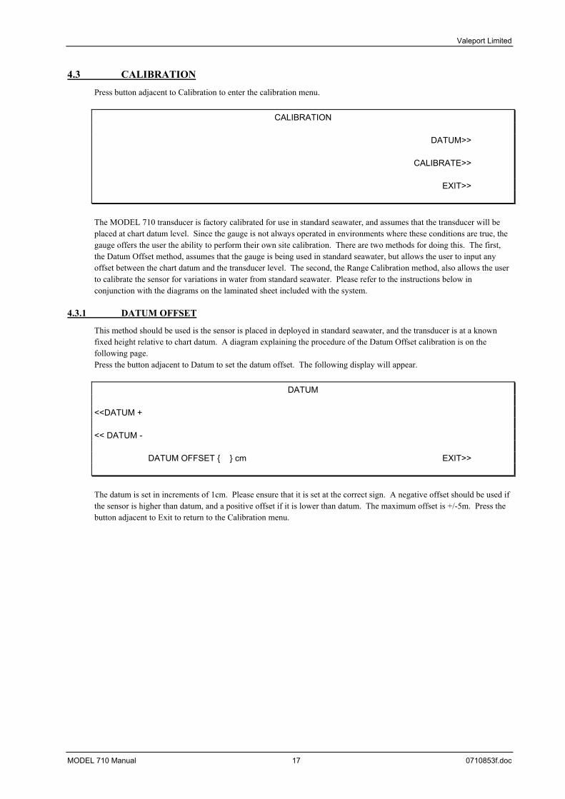
4.3 CALIBRATION
Press button adjacent to Calibration to enter the calibration menu.
CALIBRATION
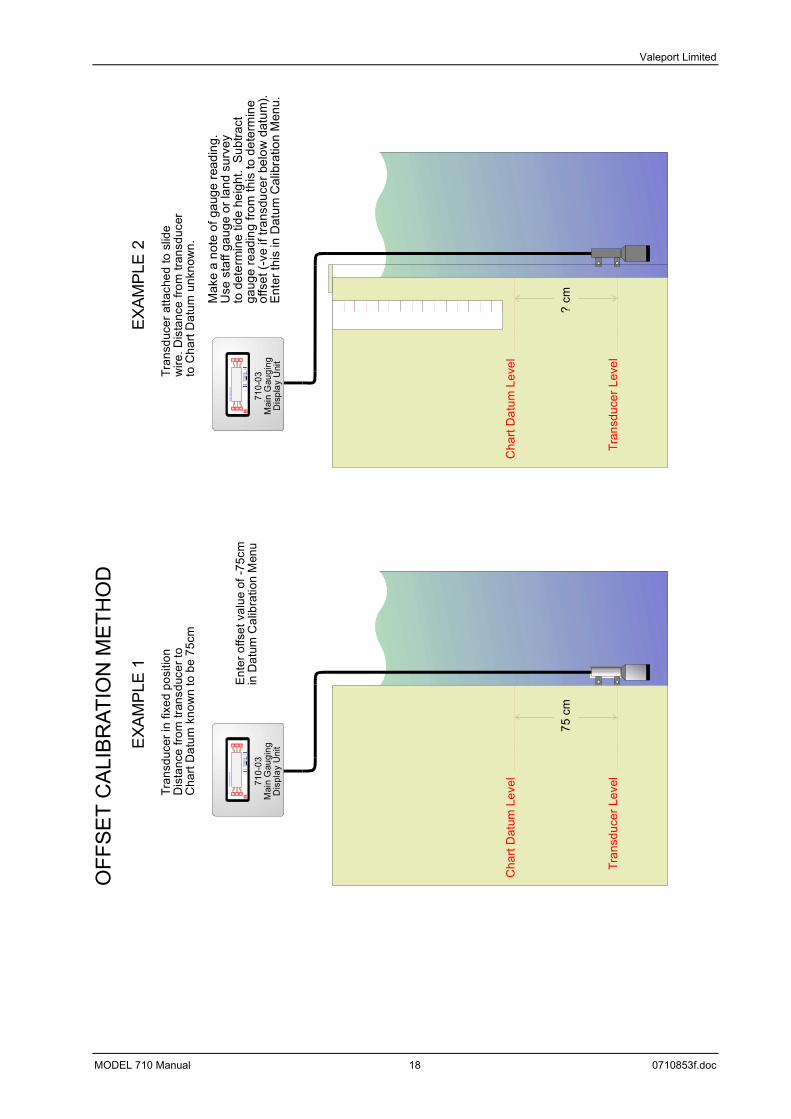
DATUM>> CALIBRATE>> EXIT>> The MODEL 710 transducer is factory calibrated for use in standard seawater, and assumes that the transducer will be placed at chart datum level. Since the gauge is not always operated in environments where these conditions are true, the gauge offers the user the ability to perform their own site calibration. There are two methods for doing this. The first, the Datum Offset method, assumes that the gauge is being used in standard seawater, but allows the user to input any offset between the chart datum and the transducer level. The second, the Range Calibration method, also allows the user to calibrate the sensor for variations in water from standard seawater. Please refer to the instructions below in conjunction with the diagrams on the laminated sheet included with the system.
4.3.1 DATUM OFFSET
This method should be used is the sensor is placed in deployed in standard seawater, and the transducer is at a known fixed height relative to chart datum. A diagram explaining the procedure of the Datum Offset calibration is on the following page. Press the button adjacent to Datum to set the datum offset. The following display will appear.
DATUM
<<DATUM + << DATUM - DATUM OFFSET cm EXIT>> The datum is set in increments of 1cm. Please ensure that it is set at the correct sign. A negative offset should be used if the sensor is higher than datum, and a positive offset if it is lower than datum. The maximum offset is +/-5m. Press the button adjacent to Exit to return to the Calibration menu.
MODEL 710 Manual 17 0710853f.doc
Valeport Limited
710-
03M
ain
Gau
ging
Dis
play
Uni
t
ON
Con
trol D
ispla
y U
nit
710-
03M
ain
Gau
ging
Dis
play
Uni
t
ON
Con
trol D
ispla
y U
nit
75 c
m?
cm
Tran
sduc
er in
fixe
d po
sitio
nD
ista
nce
from
tran
sduc
er to
Cha
rt D
atum
kno
wn
to b
e 75
cm
Tran
sduc
er a
ttach
ed to
slid
ew
ire. D
ista
nce
from
tran
sduc
erto
Cha
rt D
atum
unk
now
n.
Ente
r offs
et v
alue
of -
75cm
in D
atum
Cal
ibra
tion
Men
u
Mak
e a
note
of g
auge
read
ing.
Use
sta
ff ga
uge
or la
nd s
urve
yto
det
erm
ine
tide
heig
ht.
Subt
ract
gaug
e re
adin
g fro
m th
is to
det
erm
ine
offs
et (-
ve if
tran
sduc
er b
elow
dat
um).
Ente
r thi
s in
Dat
um C
alib
ratio
n M
enu.
EXA
MPL
E 1
EXA
MPL
E 2
OFF
SET
CA
LIB
RAT
ION
ME
THO
D
Tran
sduc
er L
evel
Tran
sduc
er L
evel
Cha
rt D
atum
Lev
elC
hart
Dat
um L
evel
MODEL 710 Manual 18 0710853f.doc
Valeport Limited
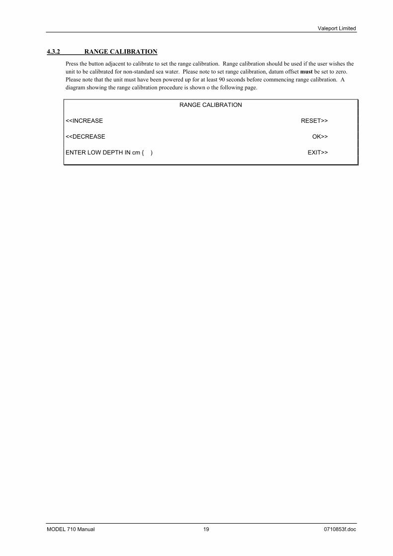
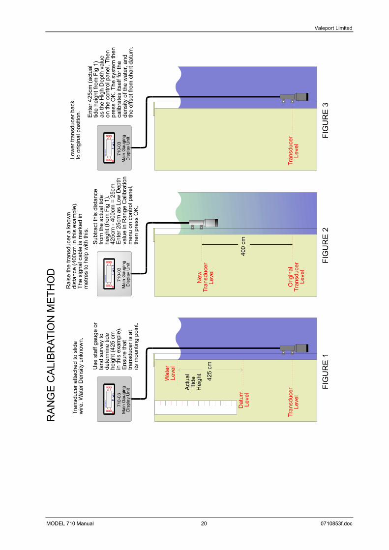
4.3.2 RANGE CALIBRATION
Press the button adjacent to calibrate to set the range calibration. Range calibration should be used if the user wishes the unit to be calibrated for non-standard sea water. Please note to set range calibration, datum offset must be set to zero. Please note that the unit must have been powered up for at least 90 seconds before commencing range calibration. A diagram showing the range calibration procedure is shown o the following page.
RANGE CALIBRATION
<<INCREASE RESET>> <<DECREASE OK>> ENTER LOW DEPTH IN cm ) EXIT>>
MODEL 710 Manual 19 0710853f.doc
Valeport Limited
FIG
UR
E 1
FIG
UR
E 2
FIG
UR
E 3
710-
03M
ain
Gau
ging
Dis
play
Uni
t
ON
Con
trol
Dis
pla
y U
nit
400
cm
Rai
se th
e tra
nsdu
cer a
kno
wn
dist
ance
(400
cm in
this
exa
mpl
e).
The
sign
al c
able
is m
arke
d in
met
res
to h
elp
with
this
.S
ubtra
ct th
is d
ista
nce
from
the
actu
al ti
dehe
ight
(fro
m F
ig 1
).42
5cm
- 40
0cm
= 2
5cm
Ent
er 2
5cm
as
Low
Dep
thva
lue
in R
ange
Cal
ibra
tion
men
u on
con
trol p
anel
,th
en p
ress
OK.
710-
03M
ain
Gau
ging
Dis
play
Uni
t
ON
Cont
rol
Dis
play
Uni
t
Low
er tr
ansd
ucer
bac
kto
orig
inal
pos
ition
.
Ent
er 4
25cm
(act
ual
tide
heig
ht fr
om F
ig 1
)as
the
Hig
h D
epth
val
ueon
the
cont
rol p
anel
. The
npr
ess
OK.
The
sys
tem
then
ca
libra
tes
itsel
f for
the
dens
ity o
f the
wat
er, a
ndth
e of
fset
from
cha
rt da
tum
.
710-
03M
ain
Gau
ging
Dis
play
Uni
t
ON
Con
trol D
ispl
ay U
nit
425
cm
Act
ual
Tide
Hei
ght
Tran
sduc
er a
ttach
ed to
slid
ew
ire. W
ater
Den
sity
unk
now
n.
Use
sta
ff ga
uge
orla
nd s
urve
y to
dete
rmin
e tid
ehe
ight
(425
cm
in th
is e
xam
ple)
.En
sure
that
trans
duce
r is
atits
mou
ntin
g po
int.
RA
NG
E C
ALI
BRAT
ION
MET
HO
D
Orig
inal
Tran
sduc
erLe
vel
New
Tran
sduc
erLe
vel
Tran
sduc
erLe
vel
Tran
sduc
erLe
vel
Dat
umLe
vel
Wat
erLe
vel
MODEL 710 Manual 20 0710853f.doc
Valeport Limited
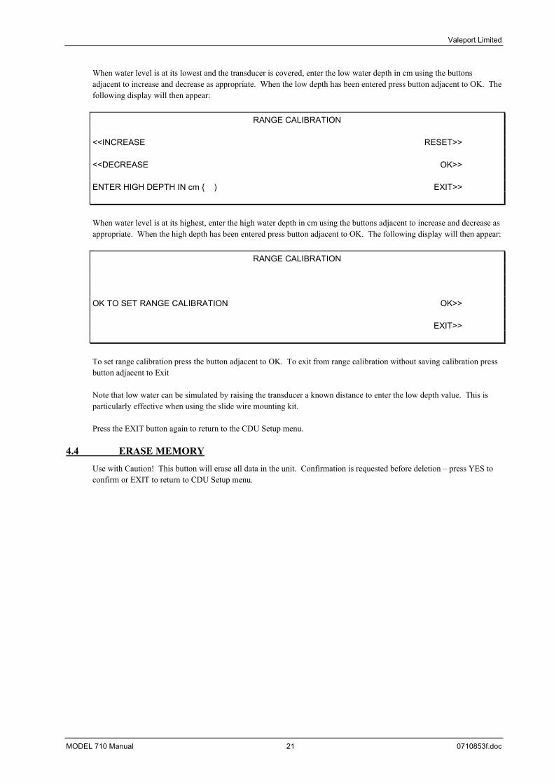
When water level is at its lowest and the transducer is covered, enter the low water depth in cm using the buttons adjacent to increase and decrease as appropriate. When the low depth has been entered press button adjacent to OK. The following display will then appear:
RANGE CALIBRATION
<<INCREASE RESET>> <<DECREASE OK>> ENTER HIGH DEPTH IN cm ) EXIT>> When water level is at its highest, enter the high water depth in cm using the buttons adjacent to increase and decrease as appropriate. When the high depth has been entered press button adjacent to OK. The following display will then appear:
RANGE CALIBRATION
OK TO SET RANGE CALIBRATION OK>> EXIT>> To set range calibration press the button adjacent to OK. To exit from range calibration without saving calibration press button adjacent to Exit Note that low water can be simulated by raising the transducer a known distance to enter the low depth value. This is particularly effective when using the slide wire mounting kit. Press the EXIT button again to return to the CDU Setup menu.
4.4 ERASE MEMORY
Use with Caution! This button will erase all data in the unit. Confirmation is requested before deletion – press YES to confirm or EXIT to return to CDU Setup menu.
MODEL 710 Manual 21 0710853f.doc
Valeport Limited
5 REMOTE RECEIVING STATION The remote receiving station should be installed following the successful installation of the gauging station(s) and the aerials. The power supply and aerial cables should be connected to the appropriate ports at the back of the unit. Please note the data input format is fixed to PC Binary. This not user changeable. To receive data from a 710 gauge, the 710 must be set to output in PC binary. The data output format of the receivers is set to PC binary.
5.1 SETTING UP THE LCD TIDE GAUGE RECEIVER
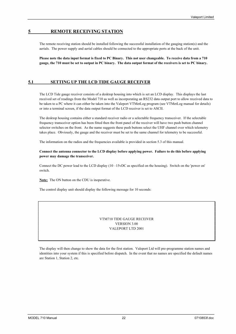
The LCD Tide gauge receiver consists of a desktop housing into which is set an LCD display. This displays the last received set of readings from the Model 710 as well as incorporating an RS232 data output port to allow received data to be taken to a PC where it can either be taken into the Valeport VTMetLog program (see VTMetLog manual for details) or into a terminal screen, if the data output format of the LCD receiver is set to ASCII. The desktop housing contains either a standard receiver radio or a selectable frequency transceiver. If the selectable frequency transceiver option has been fitted then the front panel of the receiver will have two push button channel selector switches on the front. As the name suggests these push buttons select the UHF channel over which telemetry takes place. Obviously, the gauge and the receiver must be set to the same channel for telemetry to be successful. The information on the radios and the frequencies available is provided in section 5.3 of this manual. Connect the antenna connector to the LCD display before applying power. Failure to do this before applying power may damage the transceiver. Connect the DC power lead to the LCD display (10 –15vDC as specified on the housing). Switch on the 'power on' switch. Note: The ON button on the CDU is inoperative. The control display unit should display the following message for 10 seconds:
VTM710 TIDE GAUGE RECEIVER VERSION 3.00
VALEPORT LTD 2001
The display will then change to show the data for the first station. Valeport Ltd will pre-programme station names and identities into your system if this is specified before dispatch. In the event that no names are specified the default names are Station 1, Station 2, etc.
MODEL 710 Manual 22 0710853f.doc
Valeport Limited
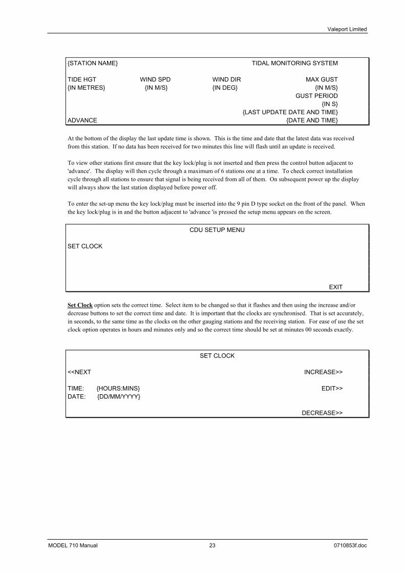
STATION NAME TIDAL MONITORING SYSTEM TIDE HGT WIND SPD WIND DIR MAX GUST IN METRES IN M/S IN DEG IN M/S GUST PERIOD IN S LAST UPDATE DATE AND TIME ADVANCE DATE AND TIME At the bottom of the display the last update time is shown. This is the time and date that the latest data was received from this station. If no data has been received for two minutes this line will flash until an update is received. To view other stations first ensure that the key lock/plug is not inserted and then press the control button adjacent to 'advance'. The display will then cycle through a maximum of 6 stations one at a time. To check correct installation cycle through all stations to ensure that signal is being received from all of them. On subsequent power up the display will always show the last station displayed before power off. To enter the set-up menu the key lock/plug must be inserted into the 9 pin D type socket on the front of the panel. When the key lock/plug is in and the button adjacent to 'advance 'is pressed the setup menu appears on the screen.
CDU SETUP MENU SET CLOCK EXIT Set Clock option sets the correct time. Select item to be changed so that it flashes and then using the increase and/or decrease buttons to set the correct time and date. It is important that the clocks are synchronised. That is set accurately, in seconds, to the same time as the clocks on the other gauging stations and the receiving station. For ease of use the set clock option operates in hours and minutes only and so the correct time should be set at minutes 00 seconds exactly.
SET CLOCK <<NEXT INCREASE>> TIME: HOURS:MINS EDIT>> DATE: DD/MM/YYYY DECREASE>>
MODEL 710 Manual 23 0710853f.doc

Valeport Limited
On completion of setup use the exit button and remove the key lock/plug. The display will now return to normal operation. STATION NAME TIDAL MONITORING SYSTEM TIDE HGT WIND SPD WIND DIR MAX GUST IN METRES IN M/S IN DEG IN M/S GUST PERIOD IN S LAST UPDATE DATE AND TIME ADVANCE DATE AND TIME The receiving unit can be connected, via the modem port to a PC for your own data logging and analysis or input into Valeport's own tidal prediction software. It is also possible to setup the receiving station using connection to a PC. To commence configuration the key lock/plug must be inserted into the 9 pin D type socket on the front of the panel and a PC connected to the unit via the PC control configuration RS232 port at the base of the housing. The receiver is configured through a Terminal emulation program such a HyperTerminal or Term.exe (supplied on the disk). When the user has interrupted the receiver the following display will appear on the control display unit until configuration has ceased:
PC Setup
PC Control
To interrupt the gauge, insert the 9 way to 9 way lead between the 9 way D connector on the front of the receiver and the comm. Port of the PC. The terminal program, term.exe, should be set to 2400 baud. Turn the receiver on and immediately type the sequence, Ctrl then E, until the line of characters breaks and you are unable to type more than two characters before the cursor moves to the next line. At this point you have establish communications with the receiver.
5.1.1 READING SERIAL NUMBER AND SOFTWARE VERSION
To read the serial number of the unit, send the command:
#003 and the unit will send the serial number To read the software version of the unit, send the command:
#015 and the unit will send the software version
5.1.2 CHANGING THE LOCAL OUTPUT FORMAT
MODEL 710 Manual 24 0710853f.doc

Valeport Limited
To change the data rate, send the command:
#011 followed by a “space” and 1<cr> for ASCII, 2 for PC binary or 3 for LED ASCII as required To read the data output format that has been set, send the command:
#012 and the unit will send the data output format set set [1, 2, or 3]
5.1.3. CHANGING THE STATION DISPLAY ORDER
To change the Station display order send the command:
#034 followed by a “space” and then the stored number range (the position of the data from the gauging station in the display order 0-5) then the gauge station ID (0-50) then the station text (user set description) required
For example, to store gauge 1 in position 0 and describe it as gauge1, enter the following #034 0 1 GAUGE1<cr>
To read the station being displayed in a specific position type #035 followed by a “space” and then the stored number range (the position of the receiver station in the display order 0-5) For example, to read the gauge in position 0, enter the following
#035 0 <cr>
5.1.4 THE ANALOGUE OUTPUT (TIDE ONLY) OPTION
The LCD receiver can be fitted with analogue outputs for the Tide height. There are two analogue outputs, one set at 0 to 5 Volts for 0 to 5m of tide and a second from 0 to 500mV for 0 to 5 m of tide. The output is labelled accordingly. Wiring schedule For the 0-5V analogue output
• Pin A is the signal ground • Pin B is the signal output • Pin C is the screen
For the 0-500mV analogue output
• Pin A is the signal ground • Pin B is the signal output • Pin C is the screen
In the case of the 0 to 500mV analogue output, 0V is equivalent to 0m tide height and 500mV is 5m. In the case of the 0 to 5V analogue output, 0V is equivalent to 0m tide height and 5V is 5m. The isolated analogue outputs are for the Tide value displayed on the screen. The voltages are held until updated by a new tide value.
MODEL 710 Manual 25 0710853f.doc
Valeport Limited
5.2 SETTING UP THE STANDARD TIDE GAUGE RECEIVER
The standard Tide gauge receiver consists of a desktop housing in which is housed either a standard receiver or selectable frequency transceiver. This receivers holds an RS232 data output port to allow received data to be taken to a PC where it can either be taken into the Valeport VTMetLog program (see VTMetLog manual for details) or into a terminal screen, if the data output format of the LCD receiver is set to ASCII. The desktop housing contains either a standard receiver radio or a selectable frequency transceiver. If the selectable frequency transceiver option has been fitted then the front panel of the receiver will have two push button channel selector switches on the front. As the name suggests these push buttons select the UHF channel over which telemetry takes place. Obviously, the gauge and the receiver must be set to the same channel for telemetry to be successful. The information on the radios and the frequencies available is provided in section 5.3 of this manual. Connect the antenna connector to the receiver before applying power. Failure to do this before applying power may damage the transceiver. Connect the DC power lead to the LCD display (10 –15vDC as specified on the housing). Applying power switches the gauge on.
5.2.1 READING SERIAL NUMBER AND SOFTWARE VERSION
To read the serial number of the unit, send the command:
#003 and the unit will send the serial number To read the software version of the unit, send the command:
#015 and the unit will send the software version
5.2.2 CHANGING THE LOCAL OUTPUT FORMAT
To change the data rate, send the command:
#011 followed by a “space” and 1<cr> for ASCII, 2 for PC binary or 3 for LED ASCII as required To read the data output format that has been set, send the command:
#012 and the unit will send the data output format set set [1, 2, or 3]
MODEL 710 Manual 26 0710853f.doc

Valeport Limited
5.3 RADIO & ANTENNA SPECIFICATIONS
The standard radio transceivers used with the Model 710 radio telemetry option are of Type MP1401, manufactured by Magenta Products Ltd. Each radio is also fitted with a Type 2519A modem board, also from Magenta. The transceivers feature selectable frequency transmission, in the UK licence exempt band of 458.5 to 458.9MHz. The channel is selected by means of push button switches connected to a Valeport microprocessor, pcb number
Valeport accept no liability for transmission failure due to interference on any specific frequency. Any necessary fees and licences are the sole responsibility of the end user.
Channel Frequency/MHz Channel Frequency/MHz 01 458.5125 19 458.7375 02 458.5250 20 458.7500 03 458.5375 21 458.7625 04 458.5500 22 458.7750 05 458.5625 23 458.7875 06 458.5750 24 458.8000 07 458.5875 25 458.8125 08 458.6000 26 458.8250 09 458.6125 27 458.8375 10 458.6250 28 458.8500 11 458.6375 29 458.8625 12 458.6500 30 458.8750 13 458.6625 31 458.8875 14 458.6750 32 458.9000 15 458.6875 33 458.9125 16 458.7000 34 458.9250 17 458.7125 35 458.9375 18 458.7250
As standard, the site radio unit is supplied with a 0dB whip antenna. The base station radio unit is supplied with a 3dB omnidirectional colinear antenna, which is also optionally available for the site radio. Both antennae have an impedance of at least 50ohm, and it is essential that they are connected to the radio before power is applied
SPECIFICATION OF RADIO STRUCTURES FUC-3 ANTENNA
Gain over ½ wave dipole 3dB VSWR Better than 1.5:1 over the operating band Maximum Input Power Rating 150W Input Impedance 50Ω Bandwidth ±2% of centre frequency Polarisation Vertical Half Power Beamwidth 32º Connection 10m length of RG213 terminated N type socket and PVC sleeve Radiating Elements Brass rod plasfilm coated Encapsulation Reinforced glass fibre tube Length 1.160m @ 460MHz Weight 1.1kg Wind Loading 6.4kgf @ wind velocity of 160kph
MODEL 710 Manual 27 0710853f.doc
Valeport Limited
6 MAINTENANCE
6.1 TRANSDUCER
The connecting cable should be checked regularly for wear and tear. The transducer unit should be periodically checked for marine growth and cleaned if necessary.
6.2 GAUGING STATION
Each gauging station should be checked regularly to ensure no water ingress and the silica gel unit replaced with a dry unit as necessary. The silica gel is blue when dry and pink when wet. It is not possible to recommend a replacement interval for the silica gel unit as this will depend upon the humidity of the installation site. It is suggested that the user checks each station on a monthly basis initially and reviews the inspection frequency in the light of experience. To dry the silica gel unit, place in an oven at 120°C for 4 hours and allow to cool in a sealed container.
MODEL 710 Manual 28 0710853f.doc

Valeport Limited
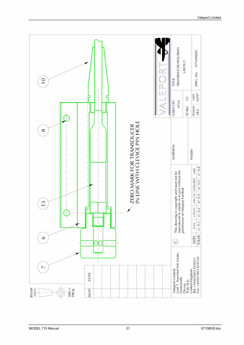
APPENDIX 1 DRAWINGS Key to Drawing 0710/068/c Drawing 0710/068/c Transducer Housing Layout Drawing 0710/069/a Slide Wire C/W Mounting Plates Drawing 0710/070/a Transducer Mounting Bottom Plate Only Drawing 0710/071/a Slide Wire to Weight c/w Top Plate
MODEL 710 Manual 29 0710853f.doc
Valeport Limited
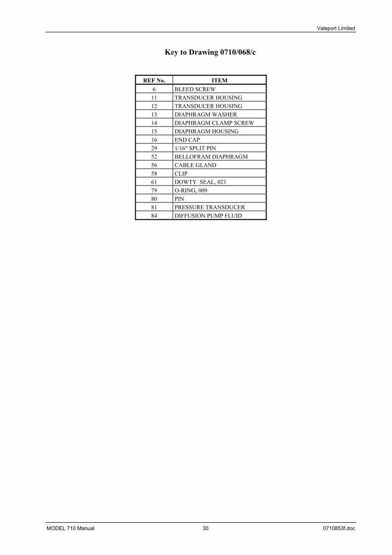
Key to Drawing 0710/068/c
REF No. ITEM 6 BLEED SCREW
11 TRANSDUCER HOUSING 12 TRANSDUCER HOUSING 13 DIAPHRAGM WASHER 14 DIAPHRAGM CLAMP SCREW 15 DIAPHRAGM HOUSING 16 END CAP 29 1/16" SPLIT PIN 52 BELLOFRAM DIAPHRAGM 56 CABLE GLAND 58 CLIP 61 DOWTY SEAL, 021 79 O-RING, 009 80 PIN 81 PRESSURE TRANSDUCER 84 DIFFUSION PUMP FLUID
MODEL 710 Manual 30 0710853f.doc
Valeport Limited
MODEL 710 Manual 31 0710853f.doc

Valeport Limited
BS30
8:1
972
PRO
J .3R
D <
STA
TEM
OD Va
lepo
rt Li
mite
d,U
nit
7, T
ow
nst
al I
nd.
Esta
te,
Dar
tmo
uth
,D
evon
,TQ
6 9L
X,U
nite
d Ki
ngdo
m.
Tel:
+44(
0)18
03 8
3403
1Fa
x: +
44(0
)180
3 83
4320
CTh
is dr
awin
g is
cop
yrig
ht a
nd m
ust n
ot b
ere
prod
uced
in w
hole
or i
n pa
rt w
ithou
t the
perm
issio
n of
Val
epor
t Lim
ited.
SIZE
STO
LER.
+/-
0.1
+/-
0.2
+/-
0.3
+/-
0.5
+/-
0.8
>150
<400
0<10
>10<
50>5
0<15
0>4
00
MA
TERI
AL
FIN
ISH
USE
D O
N
SCAL
E
DRA
WN
DAT
E
TITL
E
DRG
. No.
P.R.
A.
11/9
5
0710
PR
ESSU
RE
TR
AN
SDU
CER
BO
TT
OM
MO
UN
TIN
G P
LATE
SLID
E W
IRE
CLI
PS
SLID
E W
IRE
TOP
MO
UN
TIN
G P
LATE
TRA
NSD
UC
ER C
ON
NEC
TOR
SLID
E W
IRE
C/W
MO
UN
TIN
GPL
ATE
S
0710
/069
/A
MODEL 710 Manual 32 0710853f.doc
Valeport Limited
BS30
8:1
972
PRO
J.3R
D <
STAT
EM
OD Val
epor
t Lim
ited,
Uni
t 7, T
owns
tal I
nd. E
stat
e,D
artm
outh
,D
evon
,TQ
6 9L
X,U
nite
d Ki
ngdo
m.
Tel:
+44(
0)18
03 8
3403
1Fa
x: +
44(0
)180
3 83
4320
CTh
is d
raw
ing
is c
opyr
ight
an
d m
ust n
ot b
ere
pro
du
ced
in w
ho
le o
r in
par
t with
out
the
per
mis
sio
n o
f Val
epo
rt L
imit
ed.
SIZE
STO
LER.
+/- 0
.1+/
- 0.2
+/- 0
.3+/
- 0.5
+/- 0
.8>
150<
400
0<10
>10
<50
>50
<15
0>
400
MAT
ERIA
L
FIN
ISH
USE
D O
N
SCAL
E
DRA
WN
DAT
E
TITL
E
DRG
. No.
P.R
.A.
11/9
5
0710
PRES
SURE
TRA
NSD
UCE
R
BOTT
OM
MO
UN
TIN
G P
LATE
TRA
NSD
UCE
R CO
NN
ECTO
R
0710
/070
/A
TRA
NSD
UCE
R M
OU
NTI
NG
BOTT
OM
PLA
TE O
NLY
MODEL 710 Manual 33 0710853f.doc
Valeport Limited
BS
308
:197
2
PRO
J.3R
D <
STAT
EM
OD Va
lepo
rt Li
mite
d,U
nit 7
, Tow
nsta
l Ind
. Est
ate,
Dar
tmou
th,
Dev
on,
TQ6
9LX
,U
nite
d K
ingd
om.
Tel:
+44
(0)1
803
8340
31Fa
x: +
44(0
)180
3 83
4320
CTh
is d
raw
ing
is c
opyr
ight
and
mus
t not
be
repr
oduc
ed in
who
le o
r in
part
with
out t
hepe
rmis
sion
of V
alep
ort L
imite
d.
SIZE
STO
LER.
+/-
0.1
+/-
0.2
+/-
0.3
+/-
0.5
+/-
0.8
>150
<400
0<10
>10<
50>5
0<15
0>4
00
MAT
ERIA
L
FIN
ISH
USE
D O
N
SCAL
E
DR
AW
ND
ATE
TITL
E
DRG
. No.
P.R.
A.11
/95
0710
PRES
SURE
TRA
NSD
UCE
RSL
IDE
WIR
E CL
IPS
SLID
E W
IRE
TOP
MO
UN
TIN
G P
LATE
TRAN
SDU
CER
CON
NEC
TOR
0710
/071
/A
WEI
GH
T
SLID
E W
IRE
TO W
EIG
HT
C/W
TO
P PL
ATE
MODEL 710 Manual 34 0710853f.doc
Valeport Limited
APPENDIX 2 CALIBRATION
The calibration certificate for the Pressure transducer is given on the following page.
MODEL 710 Manual 35 0710853f.doc

Valeport Limited
MODEL 710 Manual 36 0710853f.doc
Valeport Limited
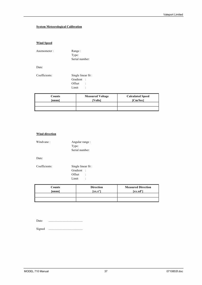
System Meteorological Calibration Wind Speed
Anemometer : Range : Type: Serial number:
Date: Coefficients: Single linear fit : Gradient : Offset : Limit :
Counts [nnnn]
Measured Voltage [Volts]
Calculated Speed [Cm/Sec]
Wind direction
Windvane : Angular range : Type: Serial number:
Date: Coefficients: Single linear fit : Gradient : Offset : Limit :
Counts [nnnn]
Direction [xx.x°]
Measured Direction [xx.xd°]
Date: ............................................ Signed ............................................
MODEL 710 Manual 37 0710853f.doc
Valeport Limited
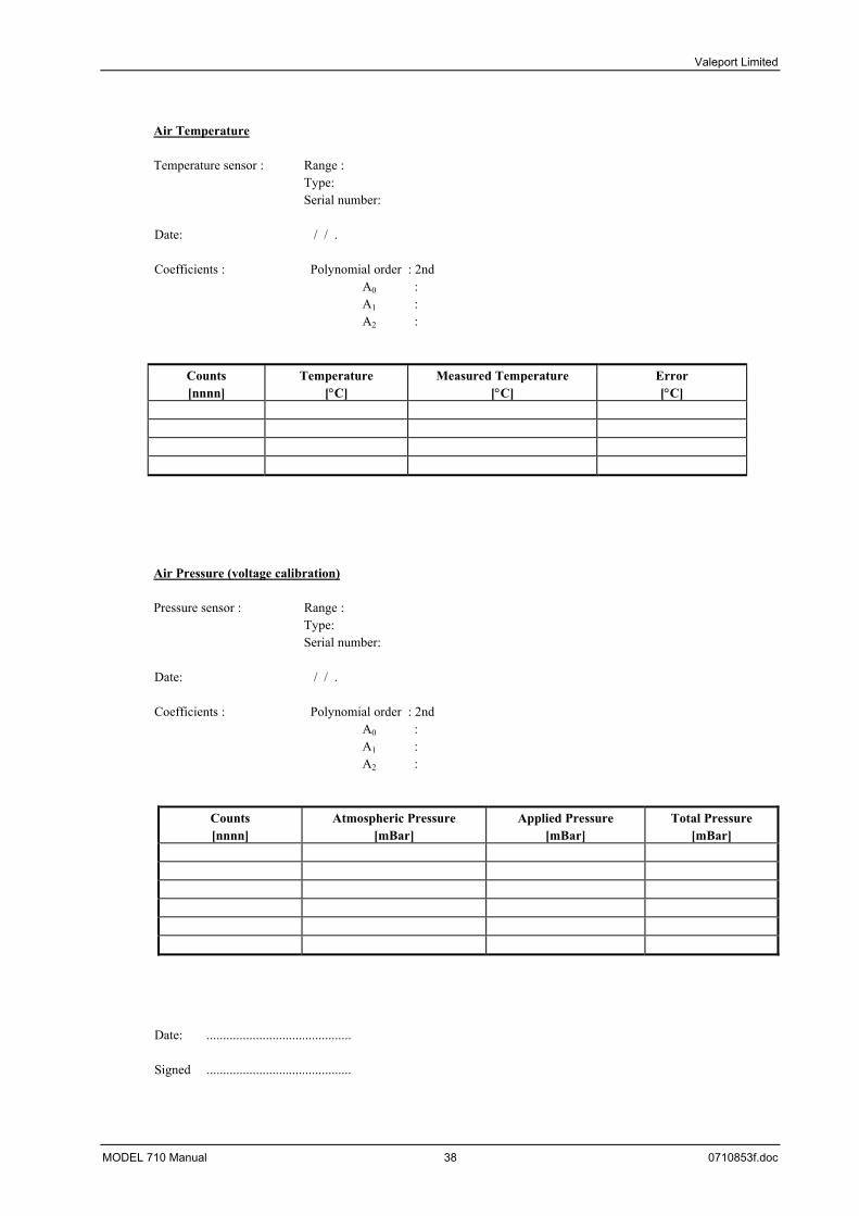
Air Temperature
Temperature sensor : Range :
Type: Serial number:
Date: / / . Coefficients : Polynomial order : 2nd A0 : A1 : A2 :
Counts [nnnn]
Temperature [°C]
Measured Temperature [°C]
Error [°C]
Air Pressure (voltage calibration)
Pressure sensor : Range : Type: Serial number:
Date: / / . Coefficients : Polynomial order : 2nd A0 : A1 : A2 :
Counts [nnnn]
Atmospheric Pressure [mBar]
Applied Pressure [mBar]
Total Pressure [mBar]
Date: ............................................ Signed ............................................
MODEL 710 Manual 38 0710853f.doc
Valeport Limited
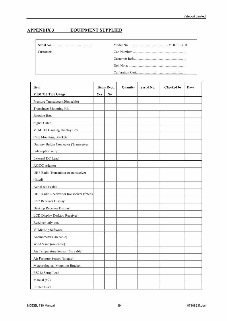
APPENDIX 3 EQUIPMENT SUPPLIED
Serial No. ........................................ … Model No.............................................. MODEL 710
Customer: Con Number: .............................................................
Customer Ref:............................................................
Del. Note: ..................................................................
Calibration Cert.: .......................................................
Item Items Reqd. Quantity Serial No. Checked by Date
VTM 710 Tide Gauge Yes No
Pressure Transducer (20m cable)
Transducer Mounting Kit
Junction Box
Signal Cable
VTM 710 Gauging Display Box
Case Mounting Brackets
Dummy Bulgin Connector (Transceiver
radio option only)
External DC Lead
AC/DC Adaptor
UHF Radio Transmitter or transceiver
(fitted)
Aerial with cable
UHF Radio Receiver or transceiver (fitted)
IP67 Receiver Display
Desktop Receiver Display
LCD Display Desktop Receiver
Receiver only box
VTMetLog Software
Anemometer (6m cable)
Wind Vane (6m cable)
Air Temperature Sensor (6m cable)
Air Pressure Sensor (integral)
Meteorological Mounting Bracket
RS232 Setup Lead
Manual (x2)
Printer Lead
MODEL 710 Manual 39 0710853f.doc
Valeport Limited
RS232 Signal Cables (Remote Displays)
MODEL 710 Manual 40 0710853f.doc
Valeport Limited
APPENDIX 4 GUARANTEE CERTIFICATE All goods are subject to a 12 month guarantee against faulty materials and bad workmanship. Any faults to be declared within 12 months from date of despatch, in writing to Valeport Limited, who will replace or repair (at their option) any faulty items caused by bad workmanship or materials, (except displays and semiconductors which are only guaranteed for a 3 month period). Valeport Limited shall be under no liability for:
1) Any consequential loss or damage of any kind whatsoever. 2) For any defect or deficiency judged by Valeport Limited to be caused by wear and tear or of
improper or unskilled handling of the goods or by any repair or attempted repair or dismantling by any one other than Valeport Limited or person's authorised to do so by Valeport Limited.
3) Batteries and other consumables supplied with the equipment which are not covered by this
guarantee. Due to the specialised nature of the instrument it should, if possible, be returned to the factory for repair or servicing. The type and serial numbers of the instrument should always be quoted, together with full details of any fault or the service required. Equipment returned to Valeport Limited for servicing must be adequately packed, preferably in the special box supplied and shipped with transportation charges prepaid. Return transport charges are also to the account of the customer.
Note: Any items supplied as part of a system which are not manufactured by Valeport Limited are covered by the individual manufacturer's guarantee of the equipment supplied.
MODEL NUMBER....................................... SERIAL NUMBER.............................................................. DATE OF DESPATCH ................................ SIGNATURE......................................................................
MODEL 710 Manual 41 0710853f.doc
Related Documents