TROUBLESHOOTING
SEMINAR MANUAL
April 2003
PART # 42-02-0052 REV. D.1
MOTION CONTROL ENGINEERING INC.
11380 WHITE ROCK ROAD, RANCHO CORDOVA, CA 95742 PHONE: (916)463-9200
INTERNATIONAL PHONE: (916) 463-9382 FAX: (916) 463-9201

TABLE OF CONTENTS
SECTION 1Job Prints
MCE NomenclatureSchematics
SECTION 2Human Interface
The Programmable ControllerThe Controller Swing PanelGroup Swing Panel
SECTION 3Selectors
LS-STANLS-QUTELS-QUADLS-QUIK
SECTION 4Advanced Diagnostics
Programmable Internal/External MemorySwing Panel Bit Addressing
SECTION 5Troubleshooting with the CRT
IMC-SCRIMC-PerformaIMC-ACIMC-MG
SECTION 6PTHC Sequence of Operation
Signal Flow
SECTION 7Troubleshooting VVMC Drives

SECTION 8Group OperationDispatching ModesOptimizing PerformancePerforma EnhancementsDiagnostics
SECTION 9SmartLink Diagnostics
SECTION 10Peripheral Communications
APPENDIX Q - QUICK REFERENCE CARDS
APPENDIX T - TECH BULLETINS

SECTION 1
JOB PRINTS
MCE NOMENCLATURE
SCHEMATICS


42-02-0052 JOB PRINTS • 1-1

• JOB PRINTS 42-02-00521-2
NOMENCLATUREMotion Control Engineering, Inc. Effective Date: 03/06/02 3 Pages
# PC BOARD DESCRIPTION 1 HC-RB4 Traction Controller Main Relay Board1 HC-RBH Hydraulic Controller Main Relay Board2 HC-CI/O Non Programmable Controller Call I/O Board2 HC-CI/O-E Programmable Controller Call I/O Expander Board3 HC-PI/O Non Programmable Controller Power I/O Board (Car A) â3 HC-PCI/O Programmable Controller Power And Call I/O Board4 HC-PI/O Non Programmable Controller Power I/O Board (Car B) â6 HC-TAB Traction Adapter Board7 HC-RDRB Rear Door Relay Board8 HC-RD Rear Door Logic Board (Car A) â9 HC-RD Rear Door Logic Board (Car B)
10 HC-DB-MOD Front G.A.L. MOD Door Interface Board11 HC-DB-MOD-R Rear G.A.L. MOD Door Interface Board12 HC-DPS Door Power Supply Board13 HC-PIX Position Indicator Expander Board (Car A) â14 HC-PIX Position Indicator Expander Board (Car B)15 HC-SRT Suicide Relay Timing Board16 HC-SCR SCR Interface Board17 HC-EQ Earthquake Board18 HC-IOX I/O(8 Input / 8 Output) Expander Board (Car A) â19 HC-IOX I/O(8 Input / 8 Output) Expander Board (Car B)20 HC-IOX Additional I/O(8 Input / 8 Output) Expander Board (Car A) â21 HC-IOX Additional I/O(8 Input / 8 Output) Expander Board (Car B)26 HC-DYNA Dynalift Interface Board27 MC-ACFR AC Feedback Relay Board28 IMC-GIO General Turbo DF I/O Board29 IMC-RB Turbo DF Relay Board30 HC-DB-MOM/H Front G.A.L. MOM/MOH Door Interface Board31 HC-DB-MOM/H-R Rear G.A.L. MOM/MOH Door Interface Board32 HC-OA Output Adapter Board33 IMC-RI M/G Relay Interface Board34 IMC-PRI M/G Power Relay Interface Board35 IMC-DIO Digital I/O Board36 IMC-DAS Data Acquisition Board37 HC-I4O I/O(16 Input /4 Output) Expander Board (Car A) â38 HC-I4O I/O(16 Input /4 Output) Expander Board (Car B)39 HC-I4O Additional I/O(16 Input / 4 Output) Expander Board (Car A) â40 HC-I4O Additional I/O(16 Input /4 Output) Expander Board (Car B)41 SCR-RI SCR/AC Relay Interface Board42 SCR-PRI SCR/AC Power Relay Interface Board43 HC-LB Lock Bypass Board44 HC-GB Gong Board

NOMENCLATUREMotion Control Engineering, Inc. Effective Date: 03/06/02 3 Pages
# PC BOARD DESCRIPTION
42-02-0052 JOB PRINTS • 1-3
45 HC-GB Additional Gong Board46 HC-SIB Selectable Input Buffer Board (Car A) â47 HC-SIB Selectable Input Buffer Board (Car B)48 HC-RT Relay Tester Board49 IMC-ACIB AC Baldor Interface Board50 HC-DPS-MOM/H Front G.A.L. MOM/MOH Door Interface and Power Supply Board51 HC-ACI AC Drive Interface Board52 HC-ACIF AC Flux Vector Interface Board53 HC-DPS-MOM/H-R Rear G.A.L. MOM/MOH Interface and Power Supply Board54 IMC-MBX IMC Enhanced Motherboard55 SCR-RIX SCR Relay Interface Extension Board56 HC-HBF A.S.M.E. Front Door Lock Bypass Board57 HC-HBFR A.S.M.E Front and Rear Door Lock Bypass Board
58 IMC-ACIM AC MagneTek Interface Board
59 HC-TACH-MG Tach Adjust Board for VVMC-MG Controller
60 HC-TACH-SCR Tach Adjust Board for VVMC-SCR Controller
61 SC-SB2K Main A17.1 - 2000 Compliant Relay Board
62 SC-HDIO High Density I/O board for A17.1 - 2000
63 SC-BASE-D Lock Bypass, Access, Overspeed and Emergency Brake Board usedwith DF controllers
64 SC-BASE Lock Bypass, Access, Overspeed and Emergency Brake Board usedwith non-DF controllers
65 SC-BASER-D Rear version of SC-BASE used with DF controllers
66 SC-BASER Rear version of SC-BASE used with non-DF controllers
67 SC-SB2K-H Hydro version of SC-SB2K
68 SC-BAH Hydro version of SC-BASE
69 SC-BAH-R Hydro version of SC-BASE with rear doorsâ Individual group cars use board numbers for car A only
NOMENCLATURE - The following is an example of the schematic symbols use to indicate that asignal either enters or exits a PC board.

• JOB PRINTS 42-02-00521-4

42-02-0052 JOB PRINTS • 1-5
FIGURE 1.1 VVMC-1000 MG Drive Page

• JOB PRINTS 42-02-00521-6
FIGURE 1.2 Page 3 – Fuse Location

42-02-0052 JOB PRINTS • 1-7
FIGURE 1.3 Safety String and Selector

• JOB PRINTS 42-02-00521-8
FIGURE 1.4 Inspection Circuits and Safety

42-02-0052 JOB PRINTS • 1-9
FIGURE 1.5 Door Interface

• JOB PRINTS 42-02-00521-10
FIGURE 1.6 General Interface
42-02-0052 JOB PRINTS • 1-11
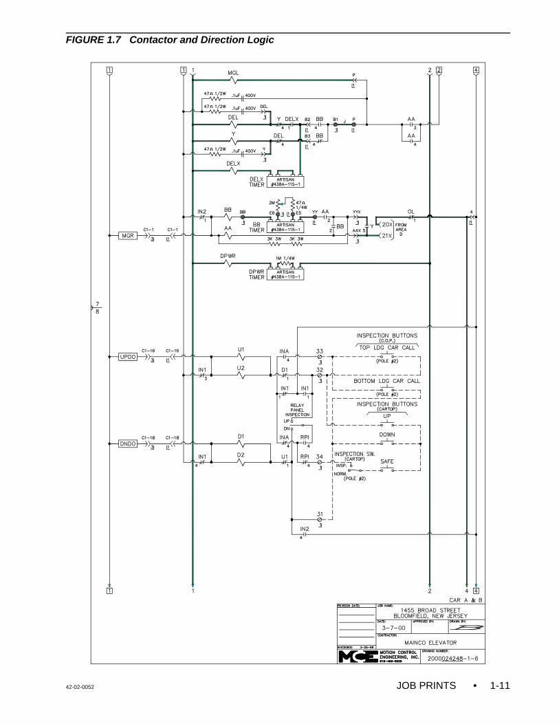
FIGURE 1.7 Contactor and Direction Logic

• JOB PRINTS 42-02-00521-12
FIGURE 1.8 Potential and Direction Pilots

42-02-0052 JOB PRINTS • 1-13
FIGURE 1.9 Door Locks

• JOB PRINTS 42-02-00521-14
FIGURE 1.10 Fire Service and Call Inputs

42-02-0052 JOB PRINTS • 1-15
FIGURE 1.11 Gongs and Position Indicators

• JOB PRINTS 42-02-00521-16
FIGURE 1.12 Gongs and Lanterns

42-02-0052 JOB PRINTS • 1-17
FIGURE 1.13 Call Inputs

• JOB PRINTS 42-02-00521-18
FIGURE 1.14 Contact and Coil Locator

42-02-0052 JOB PRINTS • 1-19
FIGURE 1.15 NEMA Motor Chart