TCAD Simulation for ePCM
Technology Development
Elisa Petroni
Advanced Simulation for NVM, LETI Innovation Days – Grenoble
28/06/2019

Outline
• Introduction
• embedded PCM for automotive applicationsMaterials and architecture optimization
• TCAD device modelingtechnology needs and simulation calibration
• TCAD test casepredictivity and architecture optimum assessment
• Different approaches & outlooks
• Conclusions
2

IntroductionST Product Family Focus
3
The leading provider of products and solutions for Smart Mobility and the Internet of Things
Portfolio delivering complementarity for target end markets, and
synergies in R&D and manufacturing
Dedicated
Automotive ICs
Discrete &
Power
Transistors
Digital
ASICs
MEMS &
Specialized
Imaging Sensors
Analog, Industrial &
Power Conversion
ICs
General Purpose &
Secure MCUs
EEPROM

IntroductionPCM Working Principles
4
Phase Change Materials:
High r logic 0 Low r logic 1
Amorphous Crystalline
SET pulse
RESET pulse
time, nsec
Te
mp
era
ture
, °C
Tmelt
Tc
• Semiconductor ternary alloy (GST), usually Ge2Sb2Te5
• Two (or more) stable phases @ Tamb amorphous vs. crystalline phases
• Reading mechanism resistance change of the GST
• Writing mechanism self-heating due to current flow (Joule effect)
GST 225 22% Ge 22% Sb 55% Te
.1
.1
.1
.2
.2
.2
.3
.3
.3
.4
.4
.5
.5
.6
.6
.7
.7
.8
.8
.9
.9
.9
.1
.1
.1
.2
.2
.2
.3
.3
.3
.4
.4
.5
.5
.6
.6
.7
.7
.8
.8
.9
.9
.9
Sb
Ge Te
.4
.5
.6
.7
.8

ePCM for AutomotiveWhy and How
5
embedded-PCM for automotive:
• Easy integration with advanced logic
• Low voltage
• No impact on CMOS front-end
• Cost-effective
• Few additional masks
• Versatility & Scalability
• Unipolar programming MOS or BJT selector depending on specific
application requirements
• Programming current scaling with cell area reduction
• Reliability
• Extrinsic reliability assessed both after soldering and for 10y @150C HTDR
ePCM cell

ePCM for AutomotiveMaterial Engineering
6
Ge-rich chalcogenide:
• Germanium content is the key to improve Tc
of Ge-Sb-Te compounds
• Tc ~ 350 °C compliant with temperature
soldering profile for automotive
TCAD ePCM ModelingTechnology Needs
7
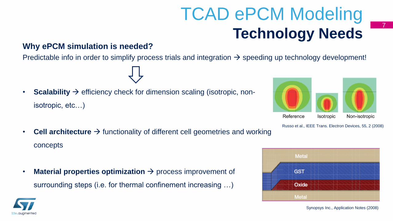
Why ePCM simulation is needed?
Predictable info in order to simplify process trials and integration speeding up technology development!
• Scalability efficiency check for dimension scaling (isotropic, non-
isotropic, etc…)
• Cell architecture functionality of different cell geometries and working
concepts
• Material properties optimization process improvement of
surrounding steps (i.e. for thermal confinement increasing …)
Russo et al., IEEE Trans. Electron Devices, 55, 2 (2008)
Synopsys Inc., Application Notes (2008)

8TCAD ePCM Modeling
Transition Rates (1/2)Phase Transition Modeling:
TCAD approaches differ for selected phase transition model
Transition Rate Equations:
SDevice by Synopsys® (→ Poisson-continuity solver)
• Each phase i is represented by volume fraction σi si = 1
• Temporal variations of si are defined by ordinary differential
equations ሶsi = σj≠iσtϵTijcij sj − eijsi
• Initial guess for si from equilibrium conditions energy, temperature
capture transition rate = c
emission transition rate = e
Tmelting = 888 K
crystalline
amorphous
Zi = giexp(−βEi)
Two phase model crystalline vs. noncrystalline
Melted state amorphous state with
physical properties for
T > Tm = melted state properties
TCAD ePCM ModelingTransition Rates (2/2)
9
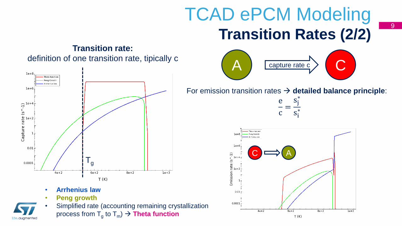
Transition rate:
definition of one transition rate, tipically cA Ccapture rate c
Tg
For emission transition rates detailed balance principle:
e
c=sj∗
si∗
C A
• Arrhenius law
• Peng growth
• Simplified rate (accounting remaining crystallization
process from Tg to Tm) Theta function
TCAD ePCM ModelingCell Structure
10
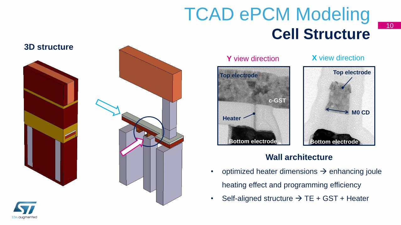
3D structure
Wall architecture
• optimized heater dimensions enhancing joule
heating effect and programming efficiency
• Self-aligned structure TE + GST + Heater
Heater
Bottom electrode
Top electrode
Bottom electrode
Top electrode
c-GST
Y view direction X view direction
M0 CD
TCAD ePCM ModelingEmulated Cell
11
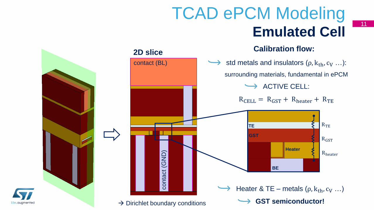
Calibration flow:
contact (BL)
conta
ct
(GN
D)
2D slice
std metals and insulators (ρ, kth, cV …):
surrounding materials, fundamental in ePCM
ACTIVE CELL:
RCELL = RGST + Rheater + RTE
RGST
RTE
Rheater
TE
BE
GST
Heater
Heater & TE – metals (ρ, kth, cV …)
GST semiconductor! Dirichlet boundary conditions

TCAD ePCM ModelingGST Material
12
GST is modeled as p-doped semiconductor
linking RGST to microscopic and transport properties
RGST = ρGST ∙ geometrical factor
In a semiconductor:
ρGST = ρ∞ eEACTkBT
ρGST =1
q(nμn + pμp)
ρGST ~1
qpμp=
1
qNVDOSμp
eEACTkBT
𝛍 calibration
Crystalline Amorphous = Melted
μn 2 150
μp 425 ൝150 at T = 300Kμpcrys
at T = 650K
𝐄𝐀𝐂𝐓 calibration
by tuning band energy structure in the two phases
(values to be considered as “effective”, that
take account of experimental 𝛒𝐆𝐒𝐓 = ρ∞)

TCAD ePCM ModelingBand Structure
13
from Adler (1978):
𝐄𝐆𝐀𝐏 = 0.5 eV → 0.715 eV
𝐄𝐓𝐑𝐀𝐏(−)
= 0.09 eV
Both crystalline and amorphous GST result in
p-doped semiconductors
EACT results consistent with experimental data

TCAD ePCM ModelingGST Calibration
14
• experimental data
simulated data
𝐑𝐒𝐄𝐓 = 𝐑∞ 𝐞𝐄𝐀𝐂𝐓𝐤𝐁𝐓
Right calibration of
ρGST = ρ∞ eEACTkBT
… but using “effective” or arbitrarily fixed values!
Experimental measurements are needed for
realistic ρGST calibration:
1. Hall measurements for μ and NVDOS
determination
2. Ellipsometry measurements for EGAP
estimation
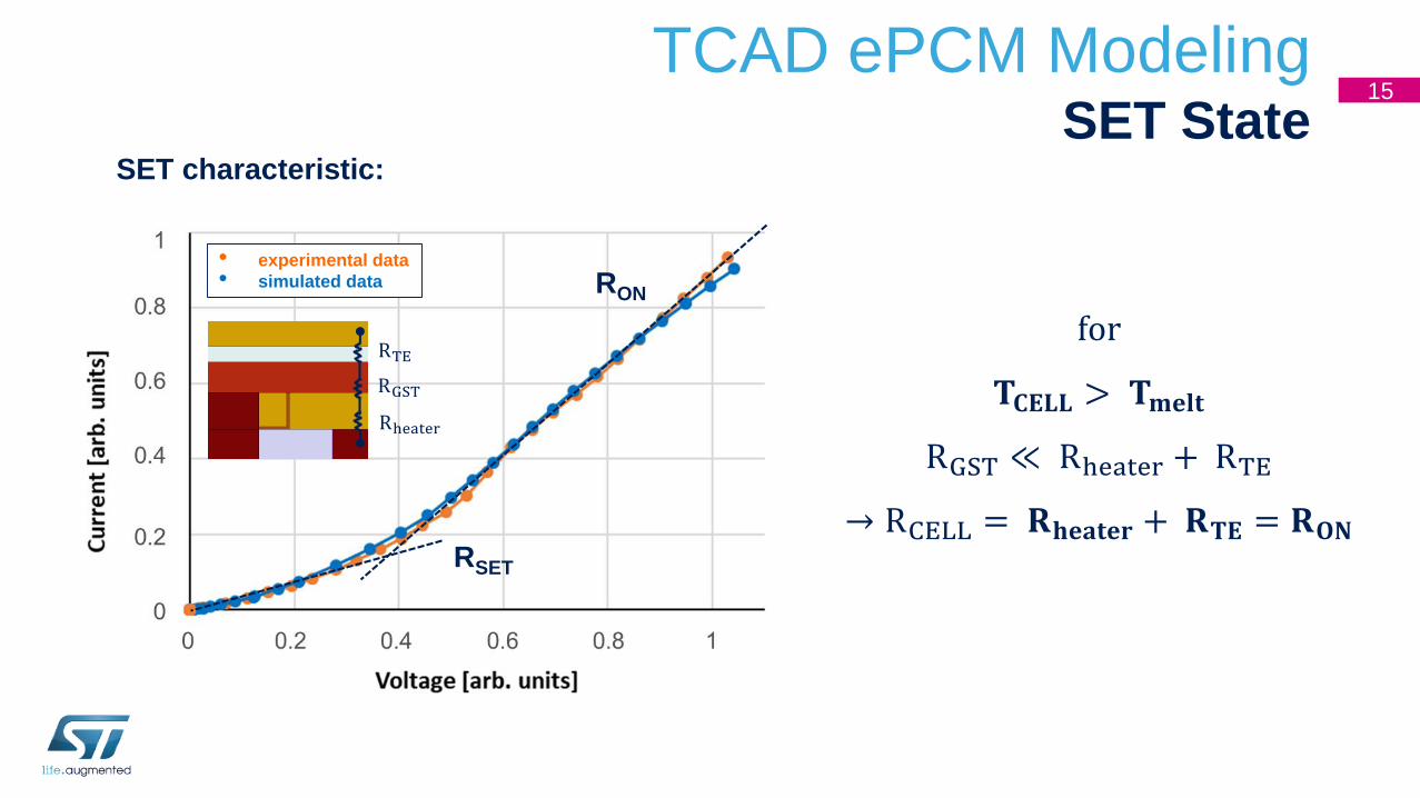
TCAD ePCM ModelingSET State
15
SET characteristic:
• experimental data
• simulated data
RSET
RON
RGST
RTE
Rheater
for
𝐓𝐂𝐄𝐋𝐋 > 𝐓𝐦𝐞𝐥𝐭
RGST ≪ Rheater + RTE
→ RCELL = 𝐑𝐡𝐞𝐚𝐭𝐞𝐫 + 𝐑𝐓𝐄 = 𝐑𝐎𝐍

TCAD ePCM Test CasePredictivity
16
Scalability:
WCELL1
WCELL2
WCELL3
WCELL4
• experimental data
• simulated data
Sensitivity:
WCELL (= M0 CD)
• experimental data
• simulated data
Hheater
Hheater 3
Hheater 2
Hheater 1
WCELL1 > WCELL2 > WCELL3 > WCELL4Hheater1 > Hheater2 > Hheater3

TCAD ePCM Test CaseSET Sensitivity
17
RON sensitivity: RSET sensitivity:
Hheater
HGST
RON ∝ Hheater
𝐑𝐎𝐍 ~ 𝐑𝐡𝐞𝐚𝐭𝐞𝐫 + 𝐑𝐓𝐄
→ less influenced by HGST
RSET ∝ Hheater
𝐑𝐒𝐄𝐓 𝐯𝐬. 𝐇𝐆𝐒𝐓
→ analytical formula?
• vs. Hheater
• vs. HGST
• vs. Hheater
• vs. HGST

18
RGST = ρGST ∙ 𝐠𝐞𝐨𝐦𝐞𝐭𝐫𝐢𝐜𝐚𝐥 𝐟𝐚𝐜𝐭𝐨𝐫RGST = ρGSTන
0
HGST dr
S(r)
RGST = ρGSTන0
HGST dr
WCELL(t + 2αr)
RGST = ρGSTln(1 +
2αHGSTt )
2αWCELL𝛂
𝟐𝛂𝐫 + 𝐭
𝐭
𝐫
𝐇𝐆𝐒𝐓
TCAD ePCM Test CaseRSET Sensitivity
α = α(V,WCELL, 𝐇𝐆𝐒𝐓)
second order effects

TCAD ePCM Test CaseImelting Optimization
19
Optimizing cell architecture in order to minimize melting current (𝐈𝐦𝐞𝐥𝐭𝐢𝐧𝐠)
888 K
𝐈𝐦𝐞𝐥𝐭𝐢𝐧𝐠
for T > Tmelting = 888 K
→ melted GST
for present range of RGST
→ Heater Heating regime
𝐈𝐦𝐞𝐥𝐭𝐢𝐧𝐠 ∝ ൗ𝟏 𝐑𝐡𝐞𝐚𝐭𝐞𝐫
vs.
𝐑𝐒𝐄𝐓 ∝ 𝐑𝐡𝐞𝐚𝐭𝐞𝐫
Lowering Imelting
decreases readout
performance
TRADE OFF is needed
T = Tamb + I2RheaterRheaterth

TCAD ePCM Test CaseGeometrical Optimum
20
𝐈𝐦𝐞𝐥𝐭𝐢𝐧𝐠 @ fixed 𝐑𝐒𝐄𝐓: when Hheater is increased, HGST is decreased and vice versa
𝐑𝐒𝐄𝐓𝟏
𝐑𝐒𝐄𝐓𝟐𝐑𝐒𝐄𝐓𝟑
𝐑𝐒𝐄𝐓𝟒
minimum of Imelting varying cell geometry
Slight increase Hheater/HGST ratio on RSET3
RSET1 < RSET2 < RSET3 < RSET4
ST CELL
increasing Hheater/HGST ratio
geometrical optimum
Trade off between heating efficiency and
hot spot position
c𝜕T
𝜕t− 𝛻 ∙ (kth𝛻T) ∝ Jn,p
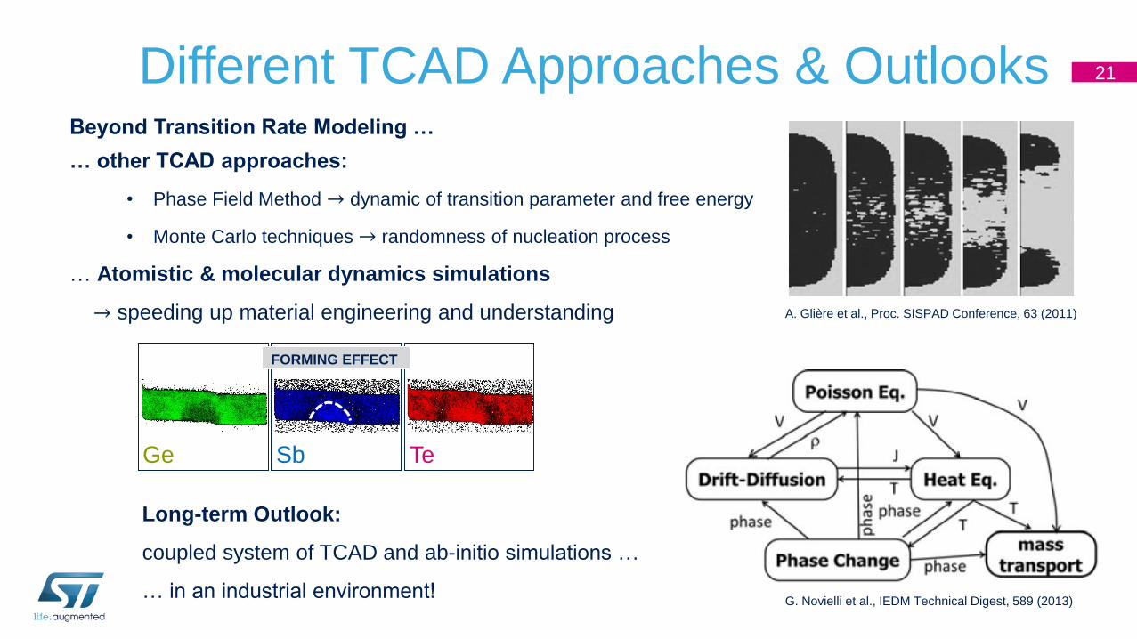
Different TCAD Approaches & Outlooks 21
Beyond Transition Rate Modeling …
… other TCAD approaches:
• Phase Field Method → dynamic of transition parameter and free energy
• Monte Carlo techniques → randomness of nucleation process
… Atomistic & molecular dynamics simulations
→ speeding up material engineering and understanding A. Glière et al., Proc. SISPAD Conference, 63 (2011)
G. Novielli et al., IEDM Technical Digest, 589 (2013)
Long-term Outlook:
coupled system of TCAD and ab-initio simulations …
… in an industrial environment!
Ge TeSb
FORMING EFFECT

Conclusions 22
• PCM solution is well positioned to match specific eNVM target
• TCAD simulation is a powerful tool yet for obtaining predictable info in terms of geometrical
scaling & sensitivity
• Correct calibration of phase change material requires deep knowledge of phase transition
physics and experimental measurements of energetic and transport properties
• Developed GST modeling is able to predict scaling efficiency and sensitivity of SET
resistivity
• Thanks to TCAD simulation, we are able to assess the geometrical optimum of our
technology, very close to present ST working point
Acknowledgments 23
ePCM team(ST Agrate)
Massimo Borghi
Elisabetta Palumbo
Octavian Melnic
Alessandro Motta
Paola Zuliani
Roberto Annunziata
For support in
TCAD model development(ST Agrate)
Lucia Zullino(ST Rousset)
Roberto Simola(ST Crolles)
Thomas Cabout
Thank you!


![VARI: CERVENKAetal.: TCAD SIMULATION OF … · The 143 process simulations have been set up in Sentaurus Workbench (SWB) of the TCAD simulation package of SYN-OPSYS [3].](https://static.cupdf.com/doc/110x72/5b5687f07f8b9a022e8c9fb2/vari-cervenkaetal-tcad-simulation-of-the-143-process-simulations-have-been.jpg)